jordon_lambert_y3_portfolio_2012-13
DESCRIPTION
Sample of my work from my final year of undergraduate study at Birmingham School of ArchitectureTRANSCRIPT

�������������
���� ����
���
����������
Co
nso
rtium
for
Cr
eative Co
nc
oc
tion
s: bu
ildin
g a n
ew bu
rslem
bric
k by br
ick
.
Design Portfolio.Jordon Lambert.
Consortium for Creative Concoctions.

Using the arts to create life and therefore Living Conceptual Time-line.
‘Deg
ener
atio
n’ o
f B
ur
slem
.
Rep
lic
ativ
e Li
brar
y I
nte
rven
tio
n I
ntr
od
uc
es C
ult
ur
e.
Th
ey e
xpan
d t
oo
qu
ick
ly e
ng
ulf
ing
.
Jobs
req
uir
ed t
o f
acil
itat
e th
e n
ew c
ult
ur
e.
Gr
aph
ic P
ubl
ish
ing
Ho
use
In
tro
du
ced
Th
e St
ory
Co
nti
nu
es...
..

Memories of Burslem
A B C D E F G H I J K L M N O P Q R S T U V W X Y Z
A - George HotelB - Red Lion InnC - Big HouseD - Town HallE - Swan Bank (Restaurant)F - Leapord Inn G - Burslem School of ArtH - Post Office Vaults I - Wedgwood Institute
J - Moorland PotteryK - House (Moorland Road)L - House (Moorland Road)M - Barclays BankN - Lloyds BankO - Royal Dalton FactoryP - Station HouseQ - United Reformed ChurchR - Queens Theatre
Burslem recorded as a medieval town: 1536
Completion of the Stoke & Mersey Canal: 1777
Burslem Created a Borough: 1871
Industrial Decline: 1970
Positively Impacts the Community
Offers a Service
Derelict
Private
S - House (Nicholas Street)T - Reliance HouseU - Burslem Police Station V - Swan Bank Methodist ChurchW - Health CenterX - Burslem Buisness ParkY - Speedy Hire GarageZ - Cemramica
Building Index Historical Era Community Impact
- Façade Brick
Concrete
Steel
Stone
Wood
Cognitive Recollection(Number of people)8-11
4-7
0-3
A B C D E F G H I J K L M N O P Q R S T U V W X Y Z
Rational to build a new burslem.
Burslem Analyzed using bespoke equipment to discover how memory
works.
Used to create accurate and emotive findings.
Temporary Library units
with a range of other uses then created Inspired the comic book
Ronin
Site then chosen in the core of the town to attempt
to regenerate the area and
positively cause gentrification.
Bricks from the old Royal Doulton then used to create
part of the new builds facade.
Fragmented design created to represent the
broken city. the glass canopy much like the design in relation to
burslem is used to link it together.
The design uses perforations to create
interesting mottled light experiences to
create a lasting impact on the person.

Eyes see image.
Parrot Camera records the image.
When the torso moves the box mirrors the movement.
As the legs move the box is fixed so that the image recorded is constant and stable.
The aim of this analysis is to better understand why cognitive memory in humans stores certain parts of the masses of data flooding into our brain. With regards to architecture, why we notice specific buildings yet if asked about a separate subsequent building, our minds can not recall this. Burslem in Stoke-On-Trent is ideal to analyse this as it has such a vast range of architectural styles and building sizes.
In science, cognition is a group of mental processes that includes attention, memory and making decisions. Can design affect this subconscious and better stimulate these processes.
The Design uses a Flip Pro Video Recorder and a bespoke piece of equipment that has been created to fit onto any individuals’ shoulder, which can be adjusted accordingly it is made of wood and painted white to attract minimal attention. It will capture the images that the human eye picks up however rather than storing them in memories, they can be documented and analysed with more rigour and efficiency.
“Studies show that memory plays a critical role in perception and decision making; however, it may be less reliable and more suggestible than once believed.” Daniel L. Schacter.
An
alys
is o
f B
ur
slem
- ‘P
arr
ot
Cam
era’
.

Recognition of Objects.
Vision.
Recognition of Objects.
Vision.
Spatial Awareness.
Hearing.
Spatial Awareness.
Hearing.
To fully understand why people cognitively react to specific building types we first need to understand the human brain. For the analysis the cognitive recognition of the architecture in the Burslem area for 12 people has been recorded: 5 Locals, 4 Architects, 2 Visitors and 1 Council Officer. This creates a complete spectrum of demographics, to give the results as much range as possible. There were 26 buildings altogether that people recalled when asked.
With regards the data has been used this to create a chart that logs the Facade detail, historical era of the buildings and the impact the building plays on the community. This could lead to a positive correlation with the number of times the buildings were recalled compared to one of these impacts, giving specific details affect how people perceive and remember a building.
InformationInput.
Short-Term Memory.
Working Memory.
Long-Term Memory.
Significance of Place.
Repetition of Data.
Where the Brain Understands Architecture.
How the Brain Creates Memories.
26 Locations in Burslem Recalled by Individuals. Ho
w M
emo
ry W
or
ks
- Ph
ysic
al A
nal
ysis
.

A
B
C
D
E F
G
H
I
J
K
L M
N
O
P
Q
R
S T
U
V
W
X
Y
Z
A -
Geo
rg
e H
ote
lB
- R
ed L
ion
In
nC
- B
ig H
ou
seD
- T
ow
n H
all
E -
Swan
Ban
k (
Res
tau
ran
t)F
- Le
apo
rd
In
n
G -
Bu
rsl
em S
ch
oo
l o
f A
rtH
- P
ost
Off
ice
Vau
lts
I -
Wed
gw
oo
d I
nst
itu
te
J -
Mo
or
lan
d P
ott
ery
K -
Ho
use
(M
oo
rla
nd
Ro
ad)
L -
Ho
use
(M
oo
rla
nd
Ro
ad)
M -
Bar
cla
ys B
ank
N -
Llo
yds
Ban
kO
- R
oya
l D
alto
n F
acto
ryP
- St
atio
n H
ou
seQ
- U
nit
ed R
efo
rm
ed
Ch
ur
ch
R -
Qu
een
s T
hea
tre
Bu
rsl
em r
eco
rd
ed
as a
med
ieva
l to
wn
: 153
6
Co
mpl
etio
n
of
the
Sto
ke
&
Mer
sey
Can
al:
1777
Bu
rsl
em C
rea
ted
a
Bo
ro
ug
h: 1
871
Ind
ust
ria
l D
ecli
ne:
197
0
Posi
tive
ly
Impa
cts
th
e C
om
mu
nit
y
Off
ers
a Se
rvic
e
Der
elic
t
Priv
ate
S -
Ho
use
(N
ich
ola
s St
ree
t)T
- R
elia
nc
e H
ou
seU
- B
ur
slem
Po
lic
e St
atio
n
V -
Sw
an B
ank
Met
ho
dis
t C
hu
rc
hW
- H
ealt
h C
ente
rX
- B
ur
slem
Bu
sin
ess
Par
kY
- Sp
eed
y H
ire
Gar
age
Z -
Cem
ram
ica
Bu
ild
ing
In
dex
H
isto
ric
al E
ra
Co
mm
un
ity
Impa
ct
- Fa
çad
eB
ric
k
Co
nc
ret
e
Stee
l
Sto
ne
Wo
od
Co
gn
itiv
e R
eco
llec
tio
n(N
um
ber
of
peo
ple)
8-11
4-7
0-3
A
B
C
D
E F
G
H
I
J
K
L M
N
O
P
Q
R
S T
U
V
W
X
Y
Z
Mem
or
ies
of
Bu
rsl
em.

Architecture is created from a culmination of senses along with a sense of place and scale to create a memory that people remember,
However as time passes this memory can often become distorted and change, maybe not by a significant amount, yet when asked to recall this memory specifics can become blurred and often change completely, to create some thing that does not exist, a place of fiction.
Many writers when writing about places use this concept by describing a place and exaggerating features, often giving the viewer/reader, a distorted view of the area, how the writer wants you to perceive this.
For this piece a vibrant narrative of Burslem was created from an individuals memories, emotions and opinions of the area and distorts the truth to create this place of fiction that literally jumps of the page. It creates a bias view of the area and the town itself; it becomes a place of fiction.
26 Locations in Burslem Recalled by Individuals.
Distortion of Burslem from memories.
Infrastructure. Burslem. Fictional Burslem. Combination.
Fictional Town: Burslem.
Tu
rn
ing
Mem
ory
In
to F
icti
on
- E
mo
tive
An
alys
is.

Library Modular Units.
Open Space. Reading Space. Discussion Space. Learning Space.
Front Elevation.
Side Elevation.
Plan View.
Modular Plans.
Ind
ivid
ual
Mo
du
le.

High Density Foam Frame with PV Solar Panels.
Lightweight Metal Skeleton.
Inflated Polymer Heat Trapping Skin.
Polymer Inflatable Bubble Skin.
Polymer Inflatable Bubble Skin.
Electricity Transfer Tube.
Steel Cable Tube.
Lightweight Metal Skeleton.
Inflatable Polymer Solar Bubble Panel Skin.
Inflated Polymer Heat Trapping Skin.
Solar Mirror ParabolicEllipse Polymer Collector.
High Density Foam Tubing.
Steel Cable Tube.
Panel Connector Tube.
This Solar Skin is made of lightweight inflatable polymer and foam tubing that is 650mm by 300mm. The panel has a solar mirror parabolic ellipse collector on the inner tube of the inflatable polymer skin. The top is made of translucent polymer and foam pieces that morph the shape of bones are put in place to add durability. The piece is lined on the outside with high-density foam that is coated in a shiny white resin finish similar to the construction of a bicycle helmet, but the foam is slightly less rigid. The skin panels fit snug together and seal to create a waterproof seal. The aesthetics of this is a very similar to the Aquarius material which helps to keep this concept strong.
Solar Skin is slotted into the waffle frame on a shelf created from joints. Inflatable Polymer Skin is inflated until the skin fits snug between the arches.Power created flows down cables in the arches into the steel base.This is then collected and utilised, excess is sold to the National Grid.
Mat
eria
l A
nal
ysis
- P
ro
vid
ing
Cle
an E
ner
gy
for
th
e Li
brar
y.

Aluminium Slat Frame.
Perpendicular Aluminium Slat Frame.
Supporting Arches.
Footing Plates.
Steel Floor.
Steel Panels and Flashing.
Supporting Beams.
Truss System.
Steel Base.
Pad Supports.Connection Joints. Footing Plates.
Connection Joint
for Multiple Module
Attachments.
The structure consists of aluminium laser cut sheets each with several ridges, the sheets slot into perpendicular sheets with identical slats to create the form. This form then slots into joints on each of the eight arches which connect to small connections bolted to the steel floor. The arch has a ridge in it where a glass panel can be slotted into if the arch is being used as an exterior entrance.
Str
uc
tur
e -
Waf
fle
Fram
e D
esig
n.

Using Literature to create Life and therefore Living .T
he
des
ign
fo
r t
he
mo
du
lar
li
brar
ies
loc
ated
ar
ou
nd
B
ur
slem
, ar
e c
on
fig
ur
ed i
n a
m
ano
r t
o a
llo
w t
he
ind
ivid
ual
u
nit
s to
co
nn
ect,
via
th
e d
oo
rw
ays,
a s
impl
e st
eel
loc
k
can
att
ach
to
an
oth
er f
ram
e to
al
low
fo
r t
he
un
its
to a
ttac
h
tog
eth
er c
rea
tin
g a
ser
ies
of
spac
es. I
nsi
de
eac
h m
od
ule
is
a li
brar
y sh
elvi
ng
un
it t
hat
is
besp
ok
e fo
r s
ever
al d
iffe
ren
t n
eed
s o
f th
e sp
ace,
th
ese
are
pref
abr
icat
ed a
nd
can
be
plac
ed
on
sit
e w
hen
req
uir
ed.
Mo
du
lar
Lib
rar
y Fi
nal
Des
ign
- m
emo
rab
le e
xper
ien
ce.
Th
e d
esig
n c
on
cep
t is
r
ou
ted
fr
om
a f
icti
tio
us
inte
llig
ent
mat
eria
l th
at
expa
nd
s an
d t
ake
ove
r a
fu
tur
isti
c d
ysto
pian
cit
y.
Bu
rsl
em i
s a
bro
ken
to
wn
, an
in
tell
igen
t m
od
ula
r u
nit
c
ou
ld h
ave
the
pote
nti
al
to e
xpan
d a
nd
en
velo
p th
e la
nd
scap
e c
rea
tin
g a
spa
ce
that
is
no
t o
nly
in
ter
esti
ng
an
d u
niq
ue
wh
ich
als
o h
as
a u
sefu
l pu
rpo
se t
o h
elp
reb
uil
d t
his
dis
join
ted
ar
ea.

Phys
ical
Par
amet
ers
Ro
yal
Do
ult
on
Sit
e , B
ur
slem
.

Phys
ical
Par
amet
ers
Ro
yal
Do
ult
on
Sit
e , B
ur
slem
.
Ch
arac
ter
App
rai
sal.

Plan
nin
g A
ppr
aisa
l

Thousands of usable materials on site with character.
Facing Bricks.
Refractory Bricks.
Engineering Bricks.
Much unusable for construction, however it can be utilised for screed ground levelling ect.
Huge stockpile of material on site.
Large Piles of slate on the site can be used for the floor, roof ect.
Reg
ain
, Rec
laim
& R
eco
ver
- E
very
Br
ick
Tel
ls i
ts O
wn
Sto
ry.
217M2 WALL CAN BE BUILT FROM BRICKS ON THE SITE.
Re-using brick, a material that resonates Stoke and Burslems history is the obvious choice to include for a design. This will help to keep the urban
grain of the conservation area and is more likely to get through a planning application for the site.
Precedents.Average Brick that was found on the site - 3.1 kg.
1 Tonne - 1,016 kg.
1 Tonne - 340 Bricks Approx.
Standard Skip 5 meters long - 7 tonnes Approx.
Approx 67 Skips worth of Bricks.
1 Skip - 2380 Bricks. Approx 159,460 Bricks.
1 in 15 Bricks are Usable.
Approx 10,630 Usable Bricks.
4900 Bricks-100m2 Wall.
Approx 217m2 Wall can be built.
=340
=159,46067
67x
= 7
10,630
4900 100m2
=
217m2
Refractory Bricks.Facing Bricks. Engineering Bricks.
Types of Bricks on Site.

Location Plan 1:2500.
A design proposal for a design incubator, prod-uct & publishing center could create jobs and be the next step of Buslems
creative master plan.
Over time these young demographics matured into talented individu-
als wanting to turn this talent into an income.
This younger demograph-ic utilised the facilities available learning off the events and work-
shops with great results.
These local creatives became an attractor for Burslem, early stages of gentrification began,
attracting various cre-atives to the area.
This rapid influx of this creatives into Burslem
meant that few relevant jobs were available and it
became difficult to establish reputations. T
he
Sto
ry s
o f
ar...
..

PRO
GR
AM
ME.
Producing Products, utilising
local creatives.
reactivate the area with features to
attract the public.
Nurturing burslems talented
creatives.
exhibitions are held weekly showcasing the creatives work
improving their reputation.
help to teach young aspiring creatives
how to design and make products.
create products for clients available to the public at the in-
house shop..
provides jobs and income for locals
creatives and burslem.
one part cultural incubator one part innovative experiment C.C.C. blends traditional philanthropy with productive
business concepts
Th
e St
ory
so
far
.....

Tr
ade
Dia
gr
am.
Local talented creatives are hired to make artistic creative products
through various mediums allowing them to gain experience
and income in there trade.
Creatives Work on Individual Products to be sold.eg. Books, Paint-
ings,Photographs.
Client asks for a product to be made
from a brief & business team market any individual pieces designed by the
creatives
Creatives then collaborate to produce
any briefed product though the mixed
media skills set in-house.
The product is finished then edited to be
showcased to the client. Any individual projects by the creatives can be
exhibited and sold in the in house store.
This all leads to income for the company and
theological talented creatives hired to help them gain credibility.
2011-2015:
o £1.4 Billion Government Funding.
o £1 Billion Lottery Funding.
o Stoke had only one grant in the last 5 years.
o Incorporating public uses in the design will improve the proposal.
o Lack of cultural facilities will help the design incubator proposal gain a successful grant.

Tr
ade
Dia
gr
am.
Idea
Exc
han
ge.

SCH
EDU
LE O
F A
cc
om
mo
dat
ion
.

SCH
EDU
LE O
F A
cc
om
mo
dat
ion
.
REC
LAIM
, REU
SE, R
EBU
ILD
.
Royal Doulton Site is partially demolished for
safety reasons.
The demolished brick building’s materials are
collected.
The bricks are used to build a new structure in
keeping with the site.
Old Royal Doulton Site comprised mainly from
brick.
Once demolished a Large stockpile of materials be-
came available on site.
This stockpile can be used to create a facade in-keeping
with the local vernacular.
The materials are collected from round
the site.
The brick can then be transported to the build
when they are needed.This can increase
efficiency and cost in the construction pro-
cess.
Process.
Recycling.
Collection.

For
m D
evel
opm
ent-
fr
agm
ente
d d
esig
n t
o l
ink
th
e c
ity
tog
eth
er.
Site with design proposal. Blurring of the public and creative space create more interactive open design.
Design decisions follow grid system, combined with historical site footprint set parameters for
the layout.
Rear private design rigid, in-keeping with the conservation area.
Front design is offset to maximise views,
Design fragmented similar to burslem and opened to maximise the E & S sunlight.

For
m D
evel
opm
ent-
fr
agm
ente
d d
esig
n t
o l
ink
th
e c
ity
tog
eth
er.
The site was previously a Victorian church, much like today the church in Burslem held a great significance to the
residents of burlsem.
the pitch roof has been adopted for the design to represent the significance of C.C.C for the residents of burslem much
like the old church.
The large pitch roof constructed from brick slips also created a way for the
design to blend into the conservation area as much of the fragmented design is
concealed by this.
For
m D
evel
opm
ent.
Above is the initial design for the graphic publishing house the design was not fragmented enough to connect to the analysis of burlsem as a broken city. the concept of using this to connect the city would be lost, also there is too much glazing used. the
design looks like one large mass rather than a series of smaller workspaces.

Fac
ade
Tes
ts-
usi
ng
a d
esig
n f
eatu
re
to c
rea
te a
las
tin
g e
xper
ien
ce.
Facade test using perforations. Glazing ans perforated brick test. model of a workspace to show effects of the perforation.
Perforated brick walls are formed by mechanical arm, R.O.B. utilized by Gramazio and Kohler to create unorthodox brick forms.
Once the algorithm is input into the machine it can create the desired design in 2m high sections, the perforations have bespoke steel reinforced bricks twice the length of a normal brick to create stability to the panel created. there are 4 perforated design that each let unique mottled light levels.

Fac
ade
Tes
ts-
usi
ng
a d
esig
n f
eatu
re
to c
rea
te a
las
tin
g e
xper
ien
ce.
FAC
AD
E T
REA
TM
ENT.
Approx 1000 Lux. 500 Lux. 400 Lux. 150 Lux.
Peter Zumthor Facade Detail - Kolumba Muse-um.
Facade Proposal Light Requirements.
Drawing 1000 - (500).
Office Room 500 - (250).
Waiting Room 400- (200).
Writer Typist 1000- (500).
Laboratory 500- (250).
Exhibitions 1000- (500).
Editing 2000.
Original Activity map of Burslem. Industrial Decline . The ‘Degeneration’ of Burslem. Burslem in 10 years in unaltered.
Facade Detail.

B.
A.
A.
C.B.
C.
Ro
of
Plan
:1:2
00.

Ro
of
Plan
:1:2
00.
Ground Floor.
1. Reception.2. Library.3. W/C.4. Server Room.5. Emergency Stair.6. Reprographics.7. Reference Library.8. Refuse Area.9. Biomass Boiler.10. Cleaning Storage11. Shop.12. Delivery Room.13. Emergency Stair.14. Workstation.15. Exhibition Space.16. Workstation.17. Workstation..18. Workstation.19. Cafe.20. W/C.21. Workstation.
Gr
ou
nd
Flo
or
1:2
00.

First Floor.
1. Workshop.2. Emergency Stairs.3. Editing Room.4. Meeting Room.5. Meeting Room.6. Office.7. Workstation.8. Workstation.9. Emergency Stairs.10. Common Room.11. Workstation.12. Meeting Room.13. Workstation.14. Exterior Balcony.15. W/C.
Fir
st F
loo
r: 1
:200
.

First Floor.
1. Workshop.2. Emergency Stairs.3. Editing Room.4. Meeting Room.5. Meeting Room.6. Office.7. Workstation.8. Workstation.9. Emergency Stairs.10. Common Room.11. Workstation.12. Meeting Room.13. Workstation.14. Exterior Balcony.15. W/C.
Fir
st F
loo
r: 1
:200
.
Second Floor.
1. Emergency Stairs.2. Meeting Room.3. Digital Workshop.4. Workstation.5. Office.6. Office.7. Meeting Room.8. Workshop.9. Workshop.10. W/C.
Roof.
1. Reflection Space.
Sec
on
d F
loo
r &
Ro
of
1:20
0.

Sec
tio
n A
-A 1
:200
an
d D
esig
n F
eatu
res
.
Private Space
Public Space.
Creative Space.
Solid Space.
Glass Canopy.
Stairs.
Circulation.
Perforated Areas.

Sec
tio
n A
-A 1
:200
an
d D
esig
n F
eatu
res
.
Fin
al D
esig
n S
ecti
on
an
d e
leva
tio
n.
Sec
tio
n b
-b a
nd
wes
ter
n e
leva
tio
n 1
:200
.

Perforated brick facade Creating mottled light Constantly varying.
Glass canopy joining the fragmented brickStructures forming a blur be-tween interior and exterior
Green Roof Suppling veg-etation for the biomass boiler and creating more intimate views.
Cantilevered Feature stairwaygiving impact on the visitors.
Skylight in the roof for the creatives to reflect over vast views of Stoke-on-Trent.
Main stair and lift to all the floors in the private area.
Atrium piercing the design funneling light in.
Structural Grid used to cerate the design. metal groves in the concrete further enhance this.
SEC
TIO
N c
-c 1
:200
Pr
om
inen
t D
esig
n F
eatu
res
.

SEC
TIO
N c
-c 1
:200
Pr
om
inen
t D
esig
n F
eatu
res
.
Per
for
atio
n E
ffec
t.

Wo
rk
stat
ion
.

EXT
ERIO
R V
IEW
.
Wo
rk
stat
ion
.
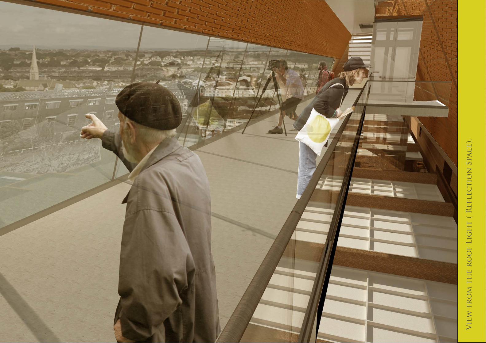
Vie
w f
ro
m t
he
ro
of
Lig
ht
( R
efle
cti
on
Spa
ce)
.

Vie
w f
ro
m t
he
ro
of
Lig
ht
( R
efle
cti
on
Spa
ce)
.
Art
ium
n V
iew
.

EXT
ERIO
R V
IEW
.

EXT
ERIO
R V
IEW
.

Rec
epti
on
.

Layout response to the Site.
sun path is most prominent from the south and East side.
slight wind vortex’s are created around the tall free standing royal doulton.
refilled land had created a useful natural drainage table.
the north east is the main source of noise on the site due to several heavy duty workshops.
The glass canopy utilities the most prominent points of the sun to gain as much natural light as possible.
The use of trees in the landscape disperses the wind preventing unpleasant gusts of wind on the landscape.
The north facade has minimal openings both to detract from the conservation area and prevent any noise pollution entering the building.
Envi
ro
nm
enta
l A
nal
ysis
.
heat recovery system (variable refrigerant flow system).o provides constant regulation of temperature through the building however it is expensive to install.
air is drawn in though vents in the lift shaft
This air is then spread through out the building to hot and cold vents.
The air can also be manually transferred throughout the building if temperatures become overly unpleasant.
p.m. sun.
midday sun.
a.m. sun.
The sw prevailing winds funnel though roads and structures to meet in the open landscape on site.
Environmental Properties on Site.
earthest underfloor Heating.o uses water from the biomass boiler to heat the various spaces. Can be expensive to replace or fix.
biomass boiler.o uses vegetation from the green roof to heat the site, can often be difficult to get vegeta-tion to power the boiler.
Heating coils are place in the screed and provide any extra heating needed to create a pleasant environment for both the public and employees.
Boiler.
Vegetation stored for fuel.
Heats a coil to power the transformer.
heats water to be used.
Providespower.
Main sources of noise.
Sun path.
Wind directions.
Drainage/ Refilled Land.
Active Systems needed to facilitate the site.
Rec
epti
on
.

Section B-B passive environmental strategy 1:200.
Section B-B active environmental strategy 1:200.
Light penetrates the south facing glazed windows for natural lighting.
Low north light passes through the perforated glass to created mottled light.
The Heat Recovery system creates an even distribution of hot and cold air round the structure.
Vegetation from the green roof is used to power the biomass boiler.
Thee Green roof creates natural thermal properties in keeping the structure at a constant temperature.
up lighting is used in the glass canopy to provide light in the evening which also creates light effects. with the brick perforations.
under-floor heating supply’s any extra heat needed to facilitate the structure during winter.
Solar controlled glass prevents glare and the building becoming to hot
Thermal mass is created from the radiation from the sun, this works most effectively in the public glazed canopy area.
Vents in the curtain walls can create fresh air cycling round the building.
Utilizing Brick on Site.
Large stockpiles of Bricks on the partially demolished royal doulton site.
Vastly reduces carbon footprint saving time and money in logistics.
Screed gravel and even facade can all be created from these bricks.
B.
B.
A.
Envi
ro
nm
enta
l A
nal
ysis
.
A.

A.
Envi
ro
nm
enta
l A
nal
ysis
.
Section A-A Summer Day 1:100. Section A-A Winter Evening 1:100.
Vents to dump hot air
thermal mass caused from solar radiation absorption.
heat recovery system(variable refrigerant flow system).
Cold air flows in through the vents.
Solar Controlled Pilkington active SunShade™.
under-floor heating.
Skylight can be a huge heat drain.
Light is funneled into the room via the skylight.
cool air is pumped from another room into the space.
cold air is pumped out and moved into a more suitable room.
Advantages.
o Light levels are extremely high in summer due to the skylight.
o The vents allow a constant cycling of fresh air to prevent the space becoming an unpleasant environment for the workers.
o The heat recovery system can collect the warm air and cycle it round the building allowing a constant temperature.
o The concrete slab will release the warm air absorbed in the day in the evening due to thermal mass.
Disadvantages.
o the solar controlled skylight and H.R.S. will be unable to prevent all the suns rays from entering the space and it may become very hot in certain times of the year.
o the heat recovery system will be expensive to install.
Advantages.
o the heat recovery system will utilize hot air from locations such as the boiler room and move it to colder spaces.
o the underfloor heating provides heat if it get too cold to use just passive systems.
o The biomass boiler provides the hot water for the boiler to prevent extravagant heat costs.
o Any heat from the minimal sun is absorbed by the concrete slab to provide thermal mass.
Disadvantages.
o the solar controlled skylight will cause large amounts of heat to be lost
o If there is an issue with the underfloor heating, it will be very expensive to replace or fix
Vents allow constant cycling of fresh air.
A.
Envi
ro
nm
enta
l A
nal
ysis
.

Rec
epti
on
Spa
ce
in t
he
Gla
ss C
ano
py.
Disadvantages.
o slow concrete production to form the concrete beams.
o the materials used to create the concrete is not environmentally friendly.
o concrete create wide columns thus wasting valuable internal space.
Advantages.
o cheap way to produce the desired structure.
o good levels of thermal mass to improve the passive environmental system.
o easily to clad for the envelope.
Concrete load-bearing floor.
Simple steel cross frame used for glass canopy.
Concrete frame for concrete roof to connect to.
reinforced concrete deck used to create the floors in-situ.
Structural fins used in canopy to create better aesthetics.
Steel Cross Frame for the Glass Canopy.
Structural glass fin.
Concrete Beam.
concrete Column.
syst
em 1
: Co
nc
ret
e c
olu
mn
gr
id f
loo
r.

syst
em 1
: Co
nc
ret
e c
olu
mn
gr
id f
loo
r.
Advantages.
o quick and simple fabrication.
o much can be prefabricated to save costs.
o the structural columns save much space on the internal of the build.
Disadvantages.
o more active heating will be needed.
o aesthetically the beams will negatively impact the glass canopy.
concrete load-bearing floor.
Steel bolts connect the structure together.
Steel Truss roof to support the brick slips.
Steel columns connect to I beams.
Steel floor joists used to support the floor.
Steel Beam.
Steel Column.
syst
em 2
: Ste
el F
ram
e.

syst
em 2
: ste
el f
ram
e.
chosen system. (best aesthetics and technological practically).
Disadvantages.
o glass fins are expensive.
o structural engineer would be needed to create the canopy frame often time consuming leading to added costs.
Advantages.
o Quick and simple fabrication
o good levels of thermal mass to improve the passive environmental system.
o aesthetically creates weightlessness in the canopy.
o environmentally sound method as lower carbon footprint
Simple steel cross frame used for glass canopy.
Structural fins used in canopy to create better aesthetics.
Hollow core floor supported on steel beams.
Steel bolts connect the structure together.
Steel Truss roof to support the brick slips.
Steel columns connect to I beams.
Structural Grid Used 6m Intervals.
Syst
em 3
: ste
el f
ram
e, g
lass
fin
s an
d h
oll
ow
co
nc
ret
e fl
oo
r.

Stee
l R
oo
f be
ams
400m
m.
Ho
llo
w F
ram
e C
on
cr
ete
Flo
or
200
mm
.
Str
uc
tur
al V
ent
for
air
cir
cu
lati
on
.
Str
uc
tur
al g
lass
an
d f
ins.
Stee
l I
beam
s 30
0mm
.
Do
ubl
e tw
ist
stai
nle
ss s
teel
Wal
l T
ies.
Stee
l Su
ppo
rtin
g D
eck
Su
bstr
uc
tur
e fo
r t
he
Br
ick
Cla
d.
Co
nc
ret
e Fl
oo
r S
lab
200m
m.
Pile
Fo
un
dat
ion
.
+400
0mm
+370
0mm
+400
0mm
Gr
ou
nd
.
Syst
em 3
: ste
el f
ram
e, g
lass
fin
s an
d h
oll
ow
co
nc
ret
e fl
oo
r.
Co
nst
ru
cti
on
sec
tio
n1:
50.
Per
for
ated
Br
ick
Cla
d
Str
uc
tur
al B
ay S
ecti
on
A-A
1:5
0.
Ground Floor.First Floor.
Second Floor.
a.
a.
Str
uc
tur
al G
rid
sys
tem
fo
r t
he
ch
ose
n m
eth
od
1:5
00.
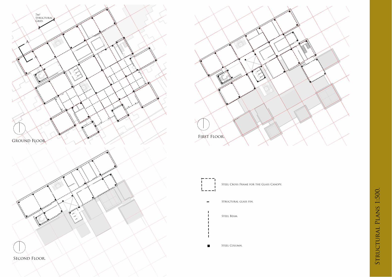
Steel Cross Frame for the Glass Canopy.
Structural glass fin.
Steel Beam.
Steel Column.
7m2
Structural Grid.
Str
uc
tur
al P
lan
s 1:
500.

Double twist stainless steel Wall Ties hold the brick to the beams and the columns.
Reinforced Steel bars are in some bespoke bricks to hold the perforation pattern in the brick wall.
Steel Supporting Deck Substructure for the Brick Clad acts as a support for the brick to sit onto.
While the concrete is still not set a steel bar is place inside to give the brick extra structural integrity.
Bespoke hollow core brick give the appearance of two bricks are placed below and above the perforations.
the prefabricated brick is filled with concrete.
Deck and wall tie connect to the steel column on the structure frame.
Brick Perforation Structural Rational.
Brick Connection to the structure.
Br
ick
Cla
d D
etai
ls.
Str
uc
tur
al P
lan
s 1:
500.

Mat
eria
l M
od
el 1
:20.

Gr
een
Ro
of
Elev
atio
n 1
;20
(red
uc
ed b
y 0.
25).

Gr
een
Ro
of
Sec
tio
n. 1
:20
(red
uc
ed b
y 0.
25).

Skyl
igh
t Se
cti
on
an
d E
leva
tio
n 1
:20
(red
uc
ed b
y 0.
25).

In accordance with part B of the building regulations.
B1 Means of Warning and Escape.
o Automatic detection and alarm system.o There is no larger than 20m to a fire stair on all of the floors.o All of the protected stair-cores exit to a fire-door leading to safety zones.
B2 Internal Fire Spread (Internal Walls).
o Use of material which inhabit the spread of fire such as brick work for internal walls double layer plasterboard and safety glass.o Self closing fire rated doors and curtain walls.
B3 Internal Fire Spread (Structure).
o Materials are encased with fire proof materials or protected with fire resistive paint to allow a specific resistive time.o This allows for the building to maintain a structural integrity to allow for a safe exit.
B4 External Fire Spread.
o External Brick clad is specified to stop the spread of fire, the brick has a natural resis-tive property to allow this.
B5 Access for Fire Services.
o There are two main access points at either side of the building this allows for emergen-cy services to access both sides to control the fire.
Fir
e St
rat
egy
1:50
0.
Ground Floor.
First Floor. Second Floor.

PLUMBING
o Soil vent pipes to be 100mm dia. Toilets to have P trap with 100mm dia. o Waste to connect to a solid and vent pipe between the brick clad and curtain wall 40mm dia waste pipes to urinals and 32mm dia. to hand basins.o Provide rodding eyes or removable traps to give access to all runs of the soil system. All traps to be 76mm deep sealed anti-vac traps. o All plumbing installations to comply with BS 5572. All boxing in for concealed service pipes to be scaled at floor and ceiling levels and service pipes which penetrate or project into hollow constructions or to flow down the gap between the curtain wall and the brick clad.
VENTILATION In accordance with part F of the building regulations.
o W/C areas to be fitted with mechanical ventilation to give min. air changes of 6 litres/second. o Vents to terminate via ridge terminal through vent tile, soffit grille or wall grille. To be fitted in accordance with manufacturers installation requirements. o All door and window frames to be draught-proof.
FLASHINGS AND CAVITY TRAYS.
o At all abutments. Code 5 lead flashings with min 150mm upstand bedded below
DRAINAGE.
o Soil vent pipe to connect via rest bend to 100mm dia drain and connect to new manhole. o All inverts, gradients and connections to be checked and approved on site to the satisfaction of the building inspector. o Any drainage under slab to be encased in 150mm concrete. o Any excess water in the clad and curtain wall can be funneled away via weepholes at the base of the brick at ground level.
ELECTRICS. In accordance with part P of the building regulations.
o Electrical Safety must be designed, installed, inspected and tested by a person competent to do so. Prior to completion the Council must be satisfied that either: A: An electrical installation certificate issued under the Competent Person Self Certification Scheme has been issued, or B: Appropriate certificates and forms defined in BS 7671 have been submitted that confirm that the work has been inspected and tested by a competent person. A compe-tent person will have sound knowledge and experience relevant to the nature of the work undertaken and to the technical standards set down in BS 7671, be fully versed in the inspection and testing procedures contained in the regulations and employ adequate testing equipment. In addition, in the case of minor works an electrician fielded to at least City and Guilds 2391 is considered to be a competent person. The person carrying out the work must arrange for a competent person to inspect the electrical installation at first fix stage and inspect and test prior to the installation.
Leg
isla
tio
n f
or
Bu
ild
ing
Reg
ula
tio
ns.

To
ng
jian
g R
ecyc
led
Br
ick
Sc
ho
ol.
Pr
eced
ent
Stu
dy.
Architects - Rufwork.
Location - Jiangxi, China.
Project Year - 2012.
Project Area - 1,096sqm.
Primary Structure - Reinforced Concrete Infill.
References - Rufwork Website: www.rufwork.com
archdaily: www.archdaily.co.uk
Ground Floor
Roof Plan.
Brick Columns. (RufWork Image) Brick Facade. (RufWork Image)
Structural Internal Columns.
A/b.
A/b.

To
ng
jian
g R
ecyc
led
Br
ick
Sc
ho
ol.
Pr
eced
ent
Stu
dy.Ground Floor
Roof Plan.
Prec
eden
t St
ud
y- S
tru
ctu
re.
Load-bearing Floor Concrete deck floor.
Pre-cast concrete frame is placed on the site, giving the initial structure.
Structural grid is used to create desired column and beam placement.
the beams are used to support the reinforced deck frame above.
Strip foundation is used in the strong clay soilwith a low water table.
concrete beam and block work.
concrete slab.
steel deckwith sheer connec-tors onto frame.
reinforced steel wire frame.
Stepped Flat Roof is levelled to create an attractive green Roof Feature.
Section A-A.

High summer sun.No sunlight penetrationminimal solar gain to south facing wall.
South prevailing winds pass through brick and cooled by shaded corridor before entering classroom.
Masonry partition with opening windows, causes natural lighting and much ventilation.
Perforated brick wall painted white to increase lighting though reflectivity.
Top hung windows shed rain.
Glazed screen with brick piers.
Rain water, heavy in summer runoff partially stored by rubble/ plants on roof.
Side hung windows increase airflow in summer.
Prec
eden
t St
ud
y- E
nvi
ro
nm
enta
l.
Section B-B.
Prec
eden
t St
ud
y- E
nvi
ro
nm
enta
l.
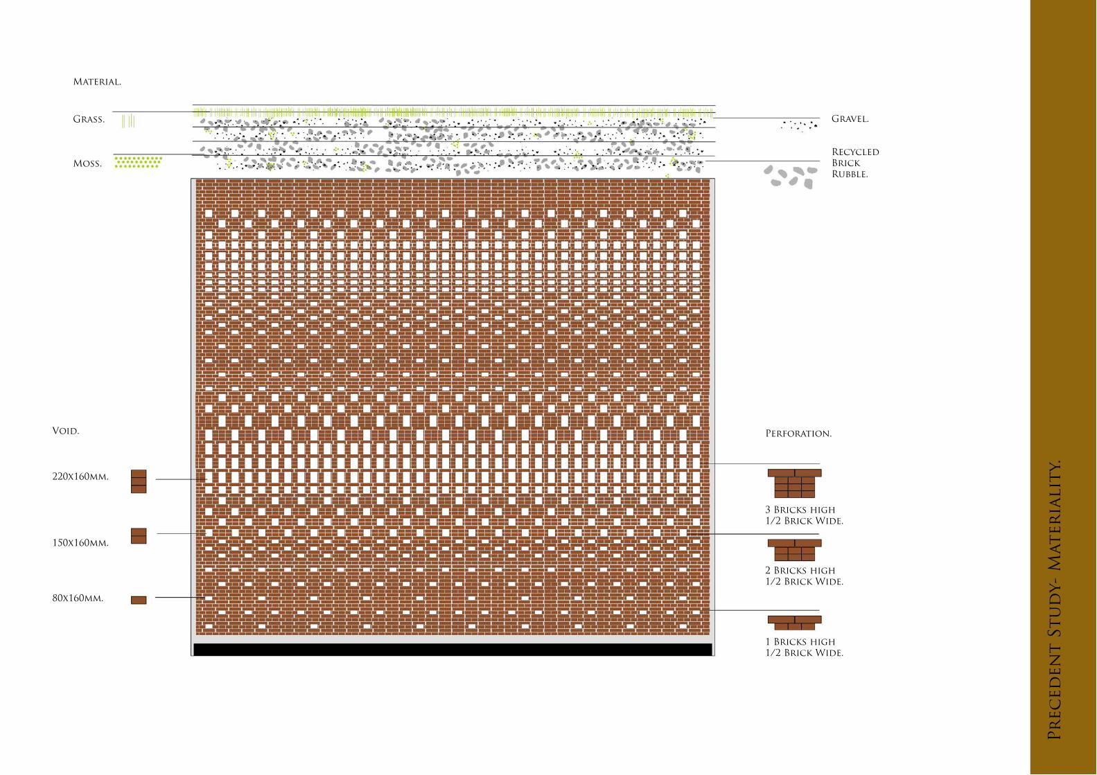
Grass.
Moss.
Gravel.
Recycled Brick Rubble.
3 Bricks high1/2 Brick Wide.
2 Bricks high1/2 Brick Wide.
1 Bricks high1/2 Brick Wide.
Perforation.
Material.
220x160mm.
150x160mm.
80x160mm.
Void.
Prec
eden
t St
ud
y- M
ater
iali
ty.