joint restraint products pvc stargrip 4000 resraint/catalog... · · 2018-02-05the actuating bolt...
TRANSCRIPT
JRCAT18.01® REGISTERED TRADEMARK OF STAR PIPE PRODUCTS
STAR® PIPE PRODUCTSHOUSTON CORPORATE TOLL FREE 1-800-999-3009 FAX 281-558-9000
www.starpipeproducts.com
Page 19
Joint Restraint Products
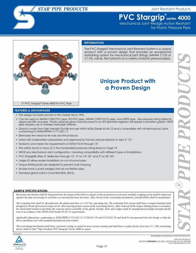
The PVC Stargrip® Mechanical Joint Restraint System is a unique product with a proven design that provides an exceptional restraining system for mechanical joint fittings (AWWA C153 or C110), valves, fire hydrants on a variety of plastic pressure pipes.
• The design has been proven in the market since 1992.
• Can be used on AWWA C900 PVC pipe, IPS PVC pipe, AWWA C909 PVCO pipe, and HDPE pipe. See pressure rating table for approved DRs and sizes. Plastic pressure pipes manufactured to an IPS diameter regimen will require a transition gasket. HDPE pipe requires use of stainless steel pipe stiffener.
• Gland is made from high strength Ductile Iron per ASTM A536 Grade 65-45-12 and is compatible with all Mechanical Joints conforming to ANSI/AWWA C111/A21.11.
• Eliminates the need for tie rods and thrust blocks
• Listed with Underwriters Laboratories and approved by Factory Mutual reserach in sizes 4”-12”.
• Tested to and meets the requirements of ASTM F1674 through 14”.
• The safety factor is twice (2:1) the standardized pressure rating listed on Page 19.
• Will fit any Mechanical Joint configuration, meaning compatibility with different types of installations.
• PVC Stargrip® offers 5º deflection through 12”, 3º on 14”-24” and 2º on 30”-36”.
• Larger ID allows easier installation on out-of-round pipe.
• Torque limiting bolts are designed to prevent over torquing.
• All sizes have curved wedges that do not flatten pipe.
• Standard gland color is Coral Red (RAL 3016).
INFORMATION
FEATURES & ADVANTAGES
SAMPLE SPECIFICATIONSRestrainer mechanism shall be integrated into the design of the follower gland. As the mechanism is activated, multiple wedging action shall be imparted against the pipe increasing its resistance as internal pressure increases. After burial of the restraining mechanism, joint flexibility shall be maintained.
The actuating bolt shall be threaded into the gland and have a 1-1/4" hex operating nut. The actuating bolt system shall have a torque-limiting head designed to break off at preset torque levels, thus insuring proper action of the restraining device. After removal of the torque-limiting head, a secondary hex head shall remain to facilitate the removal and re-assembly of the gland. Glands, bolts and wedges shall be manufactured of high strength ductile iron in accordance with ASTM A536 Grade 65-45-12 requirements.
Applicable dimensions conforming to ANSI/AWWA C111/A21.11, C110/A21.10 and C153/A21.53 and shall be incorporated into the design so that the device facilitates use with standard mechanical joint sockets.
The restraining mechanism shall have a pressure rating as stated in most current catalog and shall have a safety factor of at least 2:1. The restraining device shall be Star® Pipe Products PVC Stargrip® Series 4000 or equal.
Unique Product with a Proven Design
6" PVC Stargrip® Series 4000 for PVC Pipe
Mechanical Joint Wedge Action Restraint for Plastic Pressure Pipe
PVC Stargrip®
series 4000

® REGISTERED TRADEMARK OF STAR PIPE PRODUCTS
STAR® PIPE PRODUCTSHOUSTON CORPORATE TOLL FREE 1-800-999-3009 FAX 281-558-9000www.starpipeproducts.com
Page 20
Joint Restraint Products
JRCAT18.01
TECHNICAL INFORMATION
NOM. SIZE ØA B C1 ØD
T-BOLTSSIZE
(QTY)WEDGES (QTY) APPROX WT.
(LBS)
3 4.09 7.69 8.50 3/4 5/8 (4) 4 74 4.93 9.12 9.53 7/8 3/4 (4) 4 96 7.03 11.12 11.63 7/8 3/4 (6) 6 138 9.18 13.37 13.97 7/8 3/4 (6) 6 1710 11.23 15.62 16.18 7/8 3/4 (8) 8 2312 13.33 17.87 18.18 7/8 3/4 (8) 8 2814 15.45 20.75 20.36 7/8 3/4 (10) 10 5016 17.55 23.00 22.46 7/8 3/4 (12) 12 6018 19.65 25.25 24.56 7/8 3/4 (12) 12 6520 21.75 27.50 26.66 7/8 3/4 (14) 14 7624 25.95 32.00 30.86 7/8 3/4 (16) 16 9830 32.18 39.38 36.82 1-1/8 1 (20) 20 17336 38.48 46.25 43.12 1-1/8 1 (24) 24 219
PVC STARGRIP® 4000 SPECIFICATIONS*
*All dimensions in inches except where indicated.1 - dimension after assembly on pipe
6" PVC Stargrip® Series 4000
Mechanical Joint Wedge Action Restraint for Plastic Pressure Pipe
PVC Stargrip®
series 4000
® REGISTERED TRADEMARK OF STAR PIPE PRODUCTS
STAR® PIPE PRODUCTSHOUSTON CORPORATE TOLL FREE 1-800-999-3009 FAX 281-558-9000
www.starpipeproducts.com
Page 21
JRCAT18.01
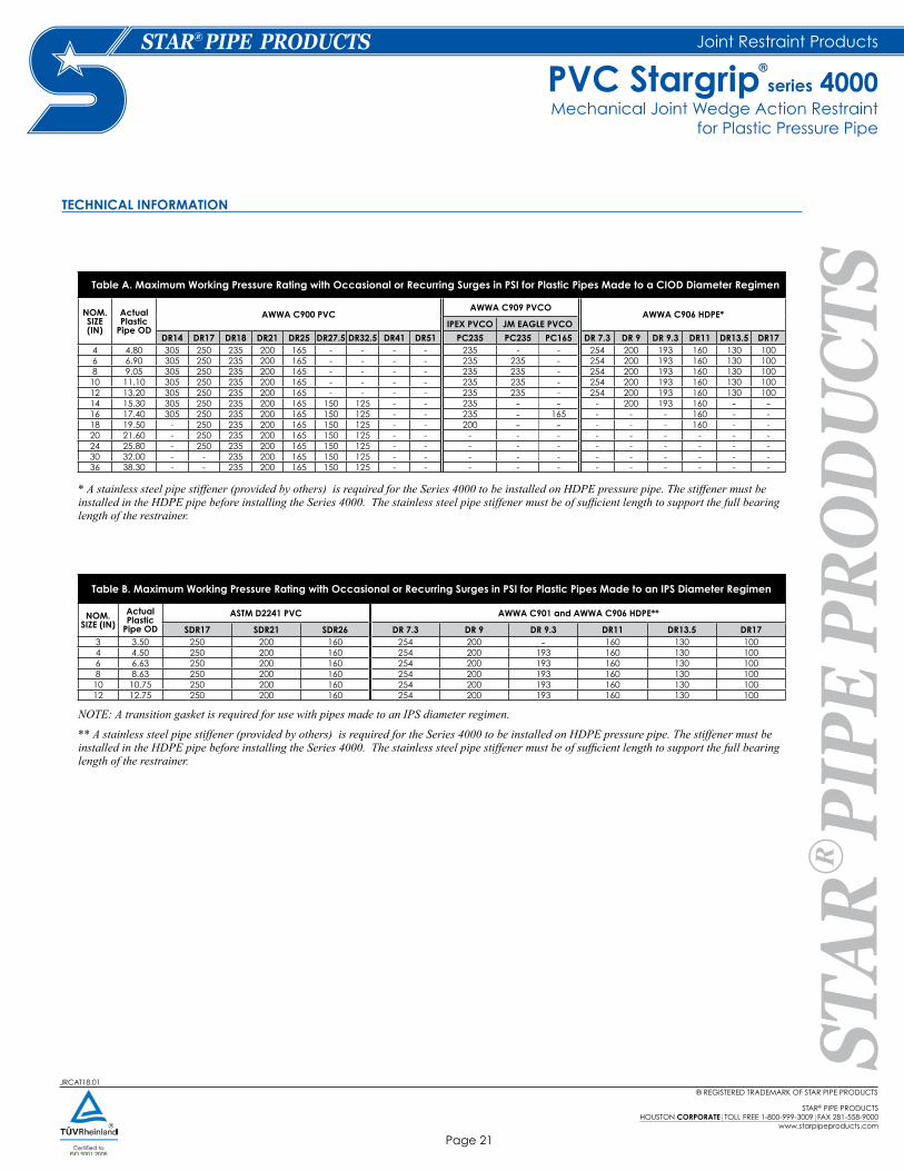
Table A. Maximum Working Pressure Rating with Occasional or Recurring Surges in PSI for Plastic Pipes Made to a CIOD Diameter Regimen
NOM.SIZE (IN)
Actual Plastic
Pipe OD
AWWA C900 PVCAWWA C909 PVCO
AWWA C906 HDPE*IPEX PVCO JM EAGLE PVCO
DR14 DR17 DR18 DR21 DR25 DR27.5 DR32.5 DR41 DR51 PC235 PC235 PC165 DR 7.3 DR 9 DR 9.3 DR11 DR13.5 DR174 4.80 305 250 235 200 165 - - - - 235 - - 254 200 193 160 130 1006 6.90 305 250 235 200 165 - - - - 235 235 - 254 200 193 160 130 1008 9.05 305 250 235 200 165 - - - - 235 235 - 254 200 193 160 130 100
10 11.10 305 250 235 200 165 - - - - 235 235 - 254 200 193 160 130 10012 13.20 305 250 235 200 165 - - - - 235 235 - 254 200 193 160 130 10014 15.30 305 250 235 200 165 150 125 - - 235 - - - 200 193 160 - -16 17.40 305 250 235 200 165 150 125 - - 235 - 165 - - - 160 - -18 19.50 - 250 235 200 165 150 125 - - 200 - - - - - 160 - -20 21.60 - 250 235 200 165 150 125 - - - - - - - - - - -24 25.80 - 250 235 200 165 150 125 - - - - - - - - - - -30 32.00 - - 235 200 165 150 125 - - - - - - - - - - -36 38.30 - - 235 200 165 150 125 - - - - - - - - - - -
Table B. Maximum Working Pressure Rating with Occasional or Recurring Surges in PSI for Plastic Pipes Made to an IPS Diameter Regimen
NOM.SIZE (IN)
Actual Plastic
Pipe OD
ASTM D2241 PVC AWWA C901 and AWWA C906 HDPE**
SDR17 SDR21 SDR26 DR 7.3 DR 9 DR 9.3 DR11 DR13.5 DR173 3.50 250 200 160 254 200 - 160 130 1004 4.50 250 200 160 254 200 193 160 130 1006 6.63 250 200 160 254 200 193 160 130 1008 8.63 250 200 160 254 200 193 160 130 10010 10.75 250 200 160 254 200 193 160 130 10012 12.75 250 200 160 254 200 193 160 130 100
* A stainless steel pipe stiffener (provided by others) is required for the Series 4000 to be installed on HDPE pressure pipe. The stiffener must be installed in the HDPE pipe before installing the Series 4000. The stainless steel pipe stiffener must be of sufficient length to support the full bearing length of the restrainer.
NOTE: A transition gasket is required for use with pipes made to an IPS diameter regimen.
** A stainless steel pipe stiffener (provided by others) is required for the Series 4000 to be installed on HDPE pressure pipe. The stiffener must be installed in the HDPE pipe before installing the Series 4000. The stainless steel pipe stiffener must be of sufficient length to support the full bearing length of the restrainer.
Joint Restraint Products
TECHNICAL INFORMATION
Mechanical Joint Wedge Action Restraint for Plastic Pressure Pipe
PVC Stargrip®
series 4000

® REGISTERED TRADEMARK OF STAR PIPE PRODUCTS
STAR® PIPE PRODUCTSHOUSTON CORPORATE TOLL FREE 1-800-999-3009 FAX 281-558-9000www.starpipeproducts.com
Page 22
JRCAT18.01
Joint Restraint Products
INSTALLATION INSTRUCTIONS - SIZES 3"- 36"
STEP 3STEP 1 STEP 2
STEP 6STEP 4 STEP 5
The rubber gasket seals more effectively if the surfaces with which it comes in contact are thoroughly cleaned just before assembly to remove all loose rust or foreign material. Lubrication and additional cleaning should be provided by brushing both the gasket and the plain end with soapy water or pipe lubricant. Slide the SERIES 4000 on the plain end, followed by the MJ gasket.
IMPORTANT: When used on IPS plastic pressure pipe, a transition MJ gasket must be used.
NOTE: If installing the Series 4000 on HDPE pressure pipe, a stainless steel pipe stiffener (provided by others) is required. The stiffener must be installed in the HDPE pipe before installing the Series 4000. The stainless steel pipe stiffener must be of sufficient length to support the full bearing length of the restrainer.
After insertion of the pipe into the bell of the fitting firmly press the gasket into the gasket recess. During this process the joint should be kept straight.
Slide the SERIES 4000 toward the MJ bell with the gland lip against the gasket. Insert T-bolts and hand tighten nuts.
IMPORTANT: Make deflection after joint is assembled but before tightening T-bolts.
While tightening T-bolts, it is essential that the gland be brought up toward the bell flange evenly, maintaining approximately the same distance between the gland and the face of the flange at all points around the socket. In order to keep the spigot fully homed in the MJ bell, the joint will need to be kept in compression until the completion of step 6.
All T-bolts should be tightened until they are within the torque range as listed in Table C. This may require multiple rounds.
Tighten the Torque – limiting twist – off bolts in a clockwise direction until all wedges are in firm contact with the pipe surface.
IMPORTANT: When installing sizes 4” through 12” on IPS plastic pipe, the spacer washers must be removed from the torque limiting bolts.
Continue tightening in an alternating manner until all of the Torque – limiting twist – off bolt heads have been twisted off.
If removal is necessary, utilize the 5/8” hex head provided. If reassembly is required, assemble the joint in the same manner as above and tighten the wedge bolt to 90 ft-lbs.
• If effective sealing is not attained at the maximum torque indicated, then the joint should be disassembled, thoroughly cleaned, and reassembled. Overstressing the bolts to compensate for poor installation practice is not acceptable.
• Not to be used on DI or steel pipe.• Stargrips must be adequately wrapped or protected if they are covered by concrete to ensure that concrete is not allowed to enter the wedge pocket.• For applications with vertical offsets please contact Star Pipe Products for technical assistance.
Table C. T-Head Bolt and Nut Details
NOM. PIPE SIZE (IN)
BOLT SIZE (IN)
RANGE OF TORQUE (FT-LBS)
AWWA C900 (PVC)
ASTM D2241 (PVC)
AWWA C909 (PVC)
AWWA C900 (PVC)
AWWA C901/AWWA C906
(HDPE)3 5/8 45 - 60 75-90
4 to 12 3/4 75-90 75-90 55-65 75-9014 to 18 3/4 75-90 75-90 75-9020 to 24 3/4 75-9030 to 36 1 100 -120
Notes:
Mechanical Joint Wedge Action Restraint for Plastic Pressure Pipe
PVC Stargrip®
series 4000

JRCAT18.01® REGISTERED TRADEMARK OF STAR PIPE PRODUCTS
STAR® PIPE PRODUCTSHOUSTON CORPORATE TOLL FREE 1-800-999-3009 FAX 281-558-9000
www.starpipeproducts.com
Page 23
Joint Restraint Products
The PVC Stargrip® Second Generation (Gen 2) Mechanical Joint Restraint System has all the performance advantages as its predecessor. However, the Gen 2 design offers these advantages with an installation that is quicker and easier. Gen 2 provides an exceptional restraint system for mechanical joint fittings (AWWA C153 or C110), valves, fire hydrants on a variety of plastic pressure pipes.
•
• Can be used on 4" through 12" AWWA C900 and AWWA C909 PVCO pipe, HDPE pipe or 3"-12" IPS PVC pipe*. (*A transition gasket is required on IPS Plastic Pipe).
• Tested to and meets the requirements of ASTM F1674.
• Listed with Underwriters Laboratories in sizes 4" to 12".
• Approved by Factory Mutual Research in sizes 4" to 12".
• The safety factor is twice (2:1) the standardized pressure rating listed on next page.
• Improved design (Gen 2) provides same performance with fewer wedges and lower wedge-bolt torque (45 to 60 ft-lbs).
• Fewer wedges and lower torque results in a quicker and easier installation.
• Gen 2 design uses a spacer that is easily removed when restraint is used on IPS Plastic pipe. Wedge bolts no longer need to be removed and reinstalled to remove spacer.
• Curved wedges reduce the amount of localized pipe deformation.
• Gen 2 offers five degrees of deflection on all sizes of AWWA C900 pipe.
• The gland’s larger inside diameter allows Gen 2 to be installed on pipe with more ovality.
• Improved design of the wedge bolts prevents over torquing which can damage PVC pipe.
• Wedges are mechanically attached to wedge bolts, which eliminates the possibility of falling out during shipping and handling.
• Gland is made from high strength Ductile Iron per ASTM A536 Grade 65-45-12 and is compatible with all Mechanical Joints that conform to ANSI/AWWA C111/A21.11. Standard gland color is Coral Red (RAL 3016).
• Eliminates the need for tie rods and thrust blocks.
• US Patent# 9,822,910
INFORMATION
FEATURES & ADVANTAGES
SAMPLE SPECIFICATIONSRestrainer mechanism shall be integrated into the design of the restraint gland. As the mechanism is activated, multiple wedge action shall be imparted against the pipe OD increasing its resistance as internal pressure increases. After burial of the restraining mechanism, joint flexibility shall be maintained.
The actuating bolt shall be threaded into the gland and have a 1-1/4" hex operating head. The actuating bolt system shall have a torque-limiting head designed to break off at preset torque levels, thus insuring proper action of the restraining device. After removal of the torque-limiting head, a secondary hex head shall remain to facilitate the removal and re-assembly of the gland. Glands, bolts and wedges shall be manufactured of high strength ductile iron in accordance with ASTM A536 Grade 65-45-12 requirements.
Applicable dimensions conforming to ANSI/AWWA C111/A21.11, C110/A21.10 and C153/A21.53 shall be incorporated into the design so that the device facilitates use with standard mechanical joint sockets.
The restraining mechanism shall have a pressure rating as stated in most current catalog and shall have a safety factor of at least 2:1. The restraining device for C900 PVC, C909 PVCO and IPS PVC Pipe shall be Star® Pipe Products second Generation PVC Stargrip® Series 4000G2 or equal.
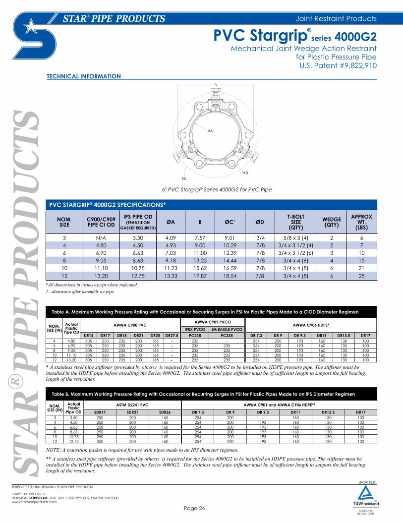
6" PVC Stargrip® Series 4000G2 for PVC Pipe
Increased performance with quicker and easier installation.
Mechanical Joint Wedge Action Restraint for Plastic Pressure Pipe U.S. Patent #9,822,910
PVC Stargrip®
series 4000G2
® REGISTERED TRADEMARK OF STAR PIPE PRODUCTS
STAR® PIPE PRODUCTSHOUSTON CORPORATE TOLL FREE 1-800-999-3009 FAX 281-558-9000www.starpipeproducts.com
Page 24
Joint Restraint Products
JRCAT18.01
TECHNICAL INFORMATION
NOM. SIZE
C900/C909PIPE CI OD
IPS PIPE OD(TRANSITION
GASKET REQUIRED)ØA B ØC1 ØD
T-BOLTSIZE
(QTY)WEDGE (QTY)
APPROX WT.
(LBS)
3 N/A 3.50 4.09 7.57 9.01 3/4 5/8 x 3 (4) 2 64 4.80 4.50 4.93 9.00 10.29 7/8 3/4 x 3 1/2 (4) 2 76 6.90 6.63 7.03 11.00 12.39 7/8 3/4 x 3 1/2 (6) 3 108 9.05 8.63 9.18 13.25 14.44 7/8 3/4 x 4 (6) 4 15
10 11.10 10.75 11.23 15.62 16.59 7/8 3/4 x 4 (8) 6 2112 13.20 12.75 13.33 17.87 18.54 7/8 3/4 x 4 (8) 6 25
PVC STARGRIP® 4000G2 SPECIFICATIONS*
*All dimensions in inches except where indicated.1 - dimension after assembly on pipe
Table A. Maximum Working Pressure Rating with Occasional or Recurring Surges in PSI for Plastic Pipes Made to a CIOD Diameter Regimen
NOM.SIZE (IN)
Actual Plastic
Pipe OD
AWWA C900 PVCAWWA C909 PVCO
AWWA C906 HDPE*IPEX PVCO JM EAGLE PVCO
DR14 DR17 DR18 DR21 DR25 DR27.5 PC235 PC235 DR 7.3 DR 9 DR 9.3 DR11 DR13.5 DR174 4.80 305 250 235 200 165 - 235 - 254 200 193 160 130 1006 6.90 305 250 235 200 165 - 235 235 254 200 193 160 130 1008 9.05 305 250 235 200 165 - 235 235 254 200 193 160 130 100
10 11.10 305 250 235 200 165 - 235 235 254 200 193 160 130 10012 13.20 305 250 235 200 165 - 235 235 254 200 193 160 130 100
Table B. Maximum Working Pressure Rating with Occasional or Recurring Surges in PSI for Plastic Pipes Made to an IPS Diameter Regimen
NOM.SIZE (IN)
Actual Plastic
Pipe OD
ASTM D2241 PVC AWWA C901 and AWWA C906 HDPE**
SDR17 SDR21 SDR26 DR 7.3 DR 9 DR 9.3 DR11 DR13.5 DR173 3.50 250 200 160 254 200 - 160 130 1004 4.50 250 200 160 254 200 193 160 130 1006 6.63 250 200 160 254 200 193 160 130 1008 8.63 250 200 160 254 200 193 160 130 10010 10.75 250 200 160 254 200 193 160 130 10012 12.75 250 200 160 254 200 193 160 130 100
* A stainless steel pipe stiffener (provided by others) is required for the Series 4000G2 to be installed on HDPE pressure pipe. The stiffener must be installed in the HDPE pipe before installing the Series 4000G2. The stainless steel pipe stiffener must be of sufficient length to support the full bearing length of the restrainer.
NOTE: A transition gasket is required for use with pipes made to an IPS diameter regimen.
** A stainless steel pipe stiffener (provided by others) is required for the Series 4000G2 to be installed on HDPE pressure pipe. The stiffener must be installed in the HDPE pipe before installing the Series 4000G2. The stainless steel pipe stiffener must be of sufficient length to support the full bearing length of the restrainer.
Mechanical Joint Wedge Action Restraint for Plastic Pressure PipeU.S. Patent #9,822,910
PVC Stargrip®
series 4000G2
6" PVC Stargrip® Series 4000G2 for PVC Pipe

® REGISTERED TRADEMARK OF STAR PIPE PRODUCTS
STAR® PIPE PRODUCTSHOUSTON CORPORATE TOLL FREE 1-800-999-3009 FAX 281-558-9000
www.starpipeproducts.com
Page 25
JRCAT18.01
Joint Restraint Products
The rubber gasket seals more effectively if the surfaces with which it comes in contact are thoroughly cleaned just before assembly. Remove all foreign material while cleaning.Lubrication and additional cleaning should be provided by brushing both the gasket and the plain end with soapy water or pipe lubricant. Slide the SERIES 4000G2 on the plain end with lip facing the plain end, followed by the MJ gasket with tapered side facing the plain end.
IMPORTANT: When installing sizes 4" through 12" on IPS PVC pipe, MJ Transition gasket must be used.
After insertion of the pipe into the bell of the fitting, firmly press the gasket into the gasket recess. During this process the joint should be kept straight.
Slide the SERIES 4000G2 toward the MJ bell with the gland lip evenly pressed against the gasket. Insert T -bolts and hand tighten nuts.
IMPORTANT: Make deflection after joint is assembled but before tightening T-bolts to required torque range as listed in table below.
While tightening T-bolts, it is essential that the gland be brought up toward the bell flange evenly, maintaining approximately the same distance between the gland and the face of the flange at all points around the socket. In order to keep the spigot fully homed in the MJ bell, the joint will need to be kept in compression until the completion of Step 6. All T-bolts should be tightened until they are within the torque range as listed in table below. This process may require multiple rounds.
Hand tighten the Torque-limiting twist-off bolts in a clockwise direction until all wedges are in firm contact with the pipe surface.
IMPORTANT: When installing sizes 4" through 12" on IPS PVC pipe, spacers must be removed from the torque-limiting bolts.
Continue tightening in an alternating manner until all of the Torque-limiting twist-off bolt heads have been twisted off. If removal is necessary, utilize the 5/8" hex head provided. If reassembly is required, assure that all of the Torque-off bolts, wedges, clips and spacers (if required) are in place. Assemble the joint in the same manner as above and tighten the wedge bolts to 45-60 ft.-lbs. using 5/8" hex head provided.
• If effective sealing is not attained at the maximum torque indicated, then the joint should be disassembled, thoroughly cleaned, and reassembled. Overstressing the bolts to compensate for poor installation practice is not acceptable.
• Not to be used on DI or steel pipe.
• PVC Stargrips must be adequately wrapped or protected if they are covered by concrete to ensure that concrete is not allowed to enter the wedge pocket.
• For applications with vertical offsets please contact Star Pipe Products for technical assistance.
* Deflection not allowed for C909.
INSTALLATION INSTRUCTIONS - SIZES 3"- 12"
STEP 3STEP 2
STEP 6STEP 4 STEP 5
Notes:
STEP 1
Table C. T-Head Bolt and Nut Details
NOM. PIPE SIZE (IN)
BOLT SIZE (IN)
RANGE OF TORQUE (FT-LBS)
AWWA C900 (PVC)
ASTM D2241 (PVC)
AWWA C909 (PVC)
AWWA C901/AWWA C906
(HDPE)3 5/8 45 - 60 75-90
4 to 12 3/4 75-90 75-90 55-65 75-90
Mechanical Joint Wedge Action Restraint for AWWA C900/C909 and IPS PVC Pipe
U.S. Patent #9,822,910
PVC Stargrip®
series 4000G2

® REGISTERED TRADEMARK OF STAR PIPE PRODUCTS
STAR® PIPE PRODUCTSHOUSTON CORPORATE TOLL FREE 1-800-999-3009 FAX 281-558-9000www.starpipeproducts.com
Page 26
NOTES:
JRCAT18.01

JRCAT18.01® REGISTERED TRADEMARK OF STAR PIPE PRODUCTS
STAR® PIPE PRODUCTSHOUSTON CORPORATE TOLL FREE 1-800-999-3009 FAX 281-558-9000
www.starpipeproducts.com
Page 27
Joint Restraint Products
6" PVC Stargrip® Series 4100P for PVC pipe
SAMPLE SPECIFICATIONSRestraint for PVC push-on bells shall incorporate the use of a solid wedge action restraint and split follower into its design. Restrainer mechanism shall be integrated into the design of the follower gland. As the mechanism is activated, multiple wedging action shall be imparted against the pipe increasing its resistance as internal pressure increases. After burial of the restraining mechanism, joint flexibility shall be maintained.
The actuating bolt shall be threaded into the gland and have a 1-1/4" hex operating nut. The actuating bolt system shall have a torque-limiting head designed to break off at preset torque levels, thus insuring proper action of the restraining device. After removal of the torque-limiting head, a secondary hex head shall remain to facilitate the removal and re-assembly of the gland. Glands, bolts and wedges shall be manufactured of high strength ductile iron in accordance with ASTM A536 Grade 65-45-12 requirements.
Applicable dimensions conforming to ANSI/AWWA C111/A21.11, C110/A21.10 and C153/A21.53 and shall be incorporated into the design so that the device facilitates use with standard mechanical joint sockets.
All sizes shall have a minimum safety factor of 2:1 (i.e. twice the product pressure rating as stated in most current catalog). The restraint mechanism shall be Star® Pipe Products, PVC Stargrip® series 4100P or approved equal.
TECHNICAL INFORMATION
*All dimensions in inches except where indicated. See page 22 for installation instructions.
New Installations Only
• For use on ANSI/AWWA C900 CI OD PVC pipe
• For new Push-On Pipe Bell installations only
• Includes PVC Stargrip®, Split Back-Up Ring and high strength low alloy steel double ended rods and nuts which meet the requirements of ANSI/AWWA C111/A21.11
• Please refer to chart for maximum bell outside diameter for rod clearance.
• The safety factor is twice (2:1) the product pressure rating (see chart on pg. 18).
• Standard gland color is Coral Red (RAL 3016).
FEATURES & ADVANTAGES
NOM. SIZE
RODS(QTY) ROD DIA x LENGTH MAX. BELL OD APPROX WT.
(LBS)
4 4 3/4 x 17 6.75 246 6 3/4 x 17 9.23 348 6 3/4 x 17 11.50 42
10 8 3/4 x 24 14.15 6112 8 3/4 x 24 16.53 7014 8 3/4 x 24 19.57 12116 10 3/4 x 24 21.13 14418 10 3/4 x 24 23.47 16120 12 3/4 x 24 25.55 18924 14 3/4 x 30 30.79 25030 18 1 x 40 37.99 47036 22 1 x 40 45.40 576
PVC STARGRIP® 4100P SPECIFICATIONS*
Wedge Action Restraint for AWWA C900 PVC Pipe BellsNew Installations Only
PVC Stargrip®
series 4100P

® REGISTERED TRADEMARK OF STAR PIPE PRODUCTS
STAR® PIPE PRODUCTSHOUSTON CORPORATE TOLL FREE 1-800-999-3009 FAX 281-558-9000www.starpipeproducts.com
Page 28
Joint Restraint Products
JRCAT18.01
• Not to be used on DI or steel pipe.
• Stargrips must be adequately wrapped or protected if they are covered by concrete to ensure that concrete is not allowed to enter the wedge pocket.
• For applications with vertical offsets please contact Star Pipe Products for technical assistance.
INSTALLATION INSTRUCTIONS - SIZES 4"- 36"
STEP 1
STEP 3 STEP 4
STEP 2
Install the remaining double-ended rods provided in each bolt hole for evenly distributing the operating load. Place nuts on the ends of each double-ended rod. It is to be ensured that adequate room is allowed on rods to fully engage the nuts with several threads showing.
Pull PVC Stargrip® Series 4000 restraint gland away from the joint until there is no slack in the rods.
Tighten the torque limiting twist off nuts in a clockwise direction until all the wedges are in firm contact with the pipe OD. Continue tightening in an alternating manner until all of the torque-limiting twist-off bolt heads have been twisted off.
The nuts on the double-ended rods must be tightened until the back-up ring is in firm contact with the back of the bell. These nuts should not be over tightened.
If removal of the PVC Stargrip® Series 4000 restraint gland is necessary, utilize the 5/8" hex head provided for 3" to 12", or 1 1/4" hex head provided for 14" to 36." If reassembly is required, assemble the product in the same manner as above and tighten the wedge bolts to 90 ft-lbs.
PVC Stargrip® Series 4100P is designed to restrain PVC Pipe, conforming to AWWA/ANSI AWWA C900/C900 (all pressure classes), push-on pipe bells. It includes a PVC Stargrip® Series 4000 gland for the spigot end and a split back-up ring behind the bell.
Place the PVC Stargrip® Series 4000 restraint gland on the spigot end of the second pipe with the lip extension facing towards the mating bell.
Assemble the PVC Pipe Push-On joint per the pipe manufacturer’s installation instructions.
Install the split back up ring, behind the pipe bell in the direction indicated on the casting. Tighten clamping bolts on the split back-up ring to 90 ft-lb.
Rotate PVC Stargrip® Series 4000 restraint gland on the spigot such that the boltholes are in alignment and adjust the position so that the distance between the glands is suitable for the double-ended rod length. Adequate room should be allowed on the double-ended rods so that nuts can be fully engaged with several threads showing.
Notes:
Wedge Action Restraint for AWWA C900 PVC Pipe BellsNew Installations Only
PVC Stargrip®
series 4100P

JRCAT18.01® REGISTERED TRADEMARK OF STAR PIPE PRODUCTS
STAR® PIPE PRODUCTSHOUSTON CORPORATE TOLL FREE 1-800-999-3009 FAX 281-558-9000
www.starpipeproducts.com
Page 29
Joint Restraint Products
PVC Stargrip® Series 4400 for PVC pipe
SAMPLE SPECIFICATIONSRestraint for PVC push-on bells (AWWA C900 CI OD) shall incorporate the use of a wedge action restraint ring and a solid harness ring into its design. Wedge action mechanisms shall be integrated into the design of the restraint ring. As the mechanisms are activated, multiple points of resistance shall be imparted onto the pipe and increase in resistance as internal pressure grows. After burial of the restraint mechanism, joint flexibility shall be maintained.
The actuating bolt shall be threaded into the restraint ring and have a 1-1/4" hex operating nut. The actuating bolt system shall have a torque-limiting head designed to break off at preset torque levels, thus insuring proper action of the restraining device. After the torque-limiting head has broken off, a secondary hex head shall remain to facilitate the removal and re-assembly of the restraint ring. Rings, bolts and wedges shall be manufactured of high strength ductile iron in accordance with ASTM A536 Grade 65-45-12 requirements.
All sizes shall have a minimum safety factor of 2:1 (i.e. twice the product pressure rating as stated in most current catalog). The restraint mechanism shall be Star® Pipe Products, PVC Stargrip® series 4400 or approved equal.
New Installations Only
The Series 4400 system consists of a restraint ring that has
wedges and wedge bolts along with a harness ring. The
wedge action restraint ring is connected to the solid harness
ring using double ended threaded rods and nuts. The system
is used to restrain AWWA C900 PVC pipe bell joints with CI
outside diameter.
• For use on ANSI/AWWA C900 CI OD PVC pipe
• For new push-on pipe bell installations only
• The restraint system includes a modified PVC Stargrip®, a solid harness ring, nuts, and double-ended rods.
• The bolt circle diameter for the modified PVC Stargrip® is larger to allow extra clearance.
• By using larger diameter rods, fewer rods are needed to achieve its rated pressure. This results in less hardware to assemble.
• The rings, wedges, and actuating bolts are made of high strength ductile iron. The restraint rods and nuts are made of high-strength-low-alloy steel per the requirements of ANSI/AWWA C111/A21.11
• Please refer to the chart on the next page for the maximum bell outside diameter that the rods can clear.
• The safety factor is twice (2:1) the product pressure rating (see chart on next page).
• The standard color for the rings is Coral Red (RAL 3016).
INFORMATION
FEATURES & ADVANTAGES
Wedge Action Bell Restraint for AWWA C900 PVC Pipe Joints (CI OD)New Installations Only
PVC Stargrip®
series 4400

® REGISTERED TRADEMARK OF STAR PIPE PRODUCTS
STAR® PIPE PRODUCTSHOUSTON CORPORATE TOLL FREE 1-800-999-3009 FAX 281-558-9000www.starpipeproducts.com
Page 30
Joint Restraint Products
JRCAT18.01
TECHNICAL INFORMATION
*All dimensions in inches except where indicated. See next page for installation instructions.
NOM. SIZE
C900 PIPE CI OD
RODS(QTY) ROD DIA x LENGTH MAX. BELL OD
"A"MAX. RESTRAINT OD
"B"APPROX WT.
(LBS)
14 15.30 5 1 x 26 20.38 23.26 10916 17.40 6 1 x 26 22.75 25.63 13418 19.50 6 1 x 26 24.88 27.76 14520 21.60 7 1 x 26 27.13 30.01 17124 25.80 8 1 1/4 x 32 31.63 35.01 26530 32.00 10 1 1/4 x 42 39.25 42.88 40936 38.30 12 1 1/4 x 42 46.13 49.76 497
PVC STARGRIP® 4400 SPECIFICATIONS*
Wedge Action Bell Restraint for AWWA C900 PVC Pipe Joints (CI OD)New Installations Only
PVC Stargrip®
series 4400
MAXIMUM WORKING PRESSURE RATING WITH OCCASSIONAL & RECURRING SURGES
NOM.SIZE (IN)
C900
DR14 DR17 DR18 DR21 DR25 DR27.5 DR32.5 DR41 DR51
14 - - 235 200 165 - 125 - -
16 - - 235 200 165 - 125 - -
18 - - 235 200 165 - 125 - -
20 - - 235 200 165 - 125 - -
24 - - 200 200 165 - 125 - -
30 - - - - 165 - 125 - -
36 - - - - 125 - 125 - -

Joint Restraint Products
® REGISTERED TRADEMARK OF STAR PIPE PRODUCTS
STAR® PIPE PRODUCTSHOUSTON CORPORATE TOLL FREE 1-800-999-3009 FAX 281-558-9000
www.starpipeproducts.com
Page 31
JRCAT18.01
INSTALLATION INSTRUCTIONS - SIZES 14"- 36"
STEP 1
STEP 3 STEP 4
STEP 2
• Due to variability of PVC pipe bell lengths, please contact Star Pipe Products if rod length is too short.
• If removal is necessary, utilize the 5/8" hex head provided.
• If reassembly is required, assemble the joint in the same manner as above and tighten the wedge bolt to 90 ft-lbs.
Tighten the torque limiting twist off bolts in a clockwise direction until all wedges are in firm contact with the pipe surface. Continue tightening in an alternating manner until all the torque limiting twist off bolt heads have been twisted off.
NOTE: If removal is necessary, utilize the 5/8" hex head provided.
Snug tighten all nuts such that the rods stick out approximately 1/2" past the nuts. Make sure that the harness ring is sitting evenly and is bearing against the pipe bell.
Caution: Do not over - tighten restraining nuts. Turn nut to hand tight plus half turn.
NOTE: If reassembly is required, assemble the joint in the same manner as above and tighten the wedge bolt to 90 ft-lbs.
After making sure that pipe and pipe surface is in good and clean condition, slide the SERIES 4400 restraint ring with lip facing spigot end of first pipe.
Slide the harness ring along the length of second pipe to fit closely behind the pipe bell.
After completing the pipe joint assembly per the pipe manufacturer instructions, position restraint ring on spigot end of pipe by inserting one of the restraint rods provided into the restrainer ears of restraint ring and harness ring such that the restraint rod ends extend past each nut approximately 1/2". Continue inserting the remaining restraint rods through restrainer ears. Leave all the nuts untightened at this moment.
NOTE: Due to variability of PVC Pipe bell lengths, please contact Star Pipe Products if rod length is too short.
Notes:
Wedge Action Bell Restraint for AWWA C900 PVC Pipe Joints (CI OD)New Installations Only
PVC Stargrip®
series 4400
® REGISTERED TRADEMARK OF STAR PIPE PRODUCTS
STAR® PIPE PRODUCTSHOUSTON CORPORATE TOLL FREE 1-800-999-3009 FAX 281-558-9000www.starpipeproducts.com
Page 32
NOTES:
JRCAT18.01