joining processesjoining processes - university of...
TRANSCRIPT

© R. Jerz 1 4/16/2006
Joining ProcessesJoining Processes
© R. Jerz 2 4/16/2006
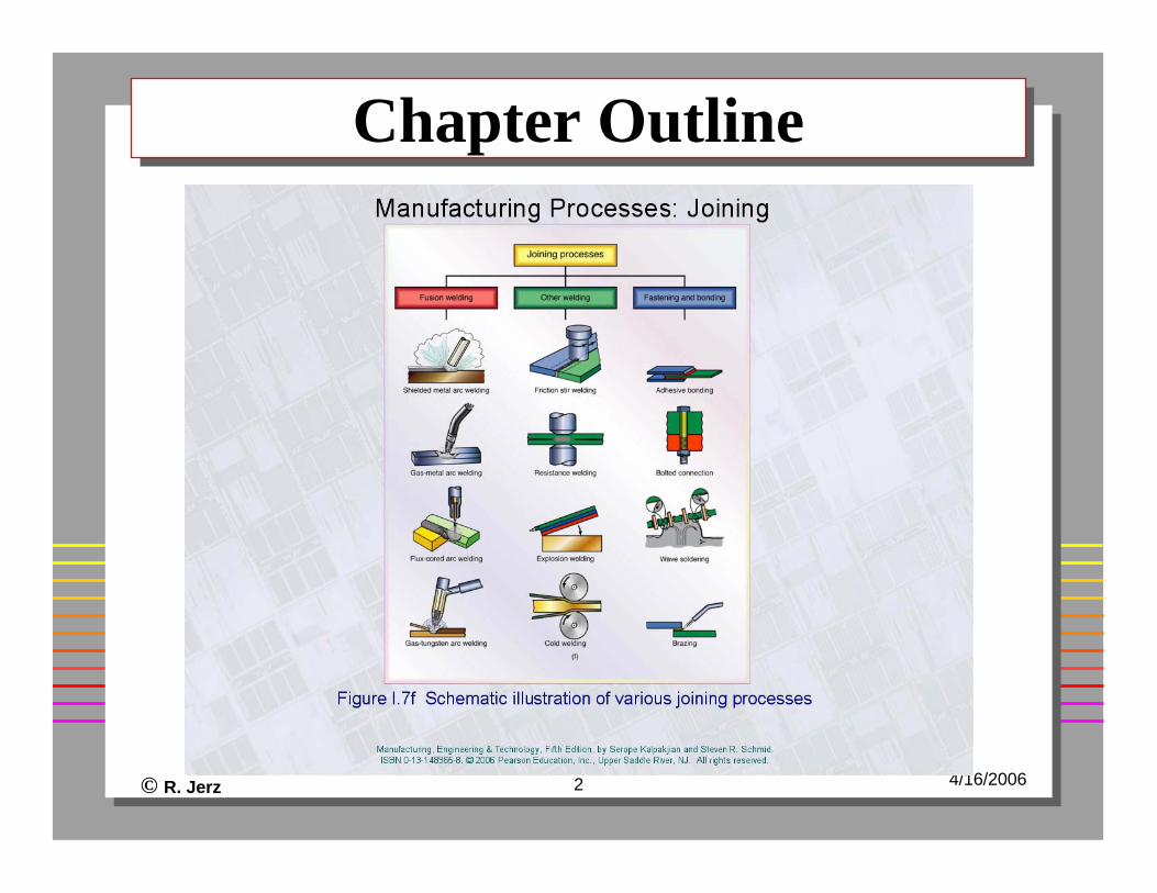
Chapter OutlineChapter Outline

© R. Jerz 3 4/16/2006
Welding ProcessesWelding Processes
Gas, electricity, or other heat source?Is electrode consumed?Is a filler material used?Is flux used?Anything else?Video – Introduction to welding
© R. Jerz 4 4/16/2006
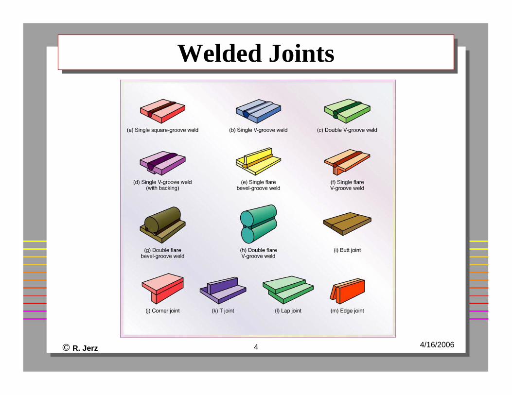
Welded JointsWelded Joints

© R. Jerz 5 4/16/2006
Fusion Welding ProcessesFusion Welding Processes
Video – Fusion welding processes

© R. Jerz 6 4/16/2006
Oxyacetylene WeldingOxyacetylene Welding
Acetylene gas most common (6,000° F)WeldingCuttingStraighteningCan be with or without filler

© R. Jerz 7 4/16/2006
Oxyacetylene TorchFigure 30.2 (a) General view of and (b) cross-section of a torch used in oxyacetylene welding. The acetylene valve is opened first; the gas is lit with a spark lighter or a pilot light; then the oxygen valve is opened and the flame adjusted. (c) Basic equipment used in oxyfuel-gas welding. To ensure correct connections, all threads on acetylene fittings are left-handed, whereas those for oxygen are right-handed. Oxygen regulators are usually painted green, and acetylene regulators red.

© R. Jerz 8 4/16/2006
Figure 30.17 Characteristics of a typical fusion-weld zone in oxyfuel-gas and arc welding.
Figure 30.18 Grain structure in (a) deep weld and (b) shallow weld. Note that the grains in the solidified weld metal are perpendicular to their interface with the base metal (see also Fig. 10.3). (c) Weld bead on a cold-rolled nickel strip produced by a laser beam. (d) Microhardness (HV) profile across a weld bead.
Weld Joint StructureWeld Joint Structure

© R. Jerz 9 4/16/2006
Arc Welding ProcessesArc Welding Processes
Nonconsumable electrode• Gas tungsten-arc (TIG)• Plasma arc (PAW)
Consumable electrode• Shielded metal arc (SMAW)• Gas metal arc (GMAW or MIG)• Flux-cored arc welding (FCAW)• Submerged arc welding (SAW)

© R. Jerz 10 4/16/2006
Figure 30.4 (a) The gas tungsten-arc welding process, formerly known as TIG (for tungsten inert gas) welding. (b) Equipment for gas tungsten-arc welding operations.
Gas-Tungsten Arc WeldingGas-Tungsten Arc Welding
Video –TIG welding

© R. Jerz 11 4/16/2006
Plasma-Arc Welding ProcessPlasma-Arc Welding Process
Video – plasma arc welding60,000 degrees F

© R. Jerz 12 4/16/2006
Figure 30.7 Schematic illustration of the shielded metal-arc welding process. About 50% of all large-scale industrial welding operations use this process.
Shielded-Metal Arc WeldingShielded-Metal Arc Welding
Video – shielded metal arc welding

© R. Jerz 13 4/16/2006
Figure 30.8 A deep weld showing the buildup sequence of eight individual weld
beads.
Shielded-Metal Arc WeldingShielded-Metal Arc Welding

© R. Jerz 14 4/16/2006
Gas Metal-Arc WeldingGas Metal-Arc Welding
Videos – gas metal arc welding

© R. Jerz 15 4/16/2006
Figure 30.11 Schematic illustration of the flux-cored arc welding process. This operation is similar to gas metal-arc welding, shown in Fig. 30.10.
Fluxed-Cored Arc-WeldingFluxed-Cored Arc-Welding
Video – flux core welding

© R. Jerz 16 4/16/2006
Figure 30.9 Schematic illustration of the submerged arc welding process and equipment. The unfused flux is recovered and reused.
Submerged-Arc WeldingSubmerged-Arc Welding
Video – submerged-are welding
© R. Jerz 17 4/16/2006
Other Welding ProcessesOther Welding Processes
Electron beam - videoLaser beam - video

© R. Jerz 18 4/16/2006
Figure 30.29 Some design guidelines for welds. Source: After J.G. Bralla.
Weld DesignWeld Design

© R. Jerz 19 4/16/2006
Welded JointsWelded Joints
Metallurgy concerns• Solidification process
Heat-affected zone -weakest part of joint

© R. Jerz 20 4/16/2006
Figure 30.19 Examples of various discontinuities in fusion welds.
Figure 30.20 Examples of various defects in fusion welds.
Defects in Fusion WeldsDefects in Fusion Welds

© R. Jerz 21 4/16/2006
Figure 30.21 Types of cracks developed in welded joints. The cracks are caused by thermal stresses, similar to the development of hot tears in castings (see also Fig. 10.12).
Cracks in Welded JointsCracks in Welded Joints

© R. Jerz 22 4/16/2006
Figure 30.23 Distortion of parts after welding. (a) Butt joints and (b) fillet welds. Distortion is caused by differential thermal expansion and contraction of different regions of the welded assembly.
Distortion of Parts After WeldingDistortion of Parts After Welding

© R. Jerz 23 4/16/2006
Figure 30.26 (a) Specimen for longitudinal tension-shear testing; (b) specimen for transfer tension-shear testing; (c) wraparound bend test method; (d) three-point bending of welded specimens (see also Fig. 2.11).
Weld TestingWeld Testing

© R. Jerz 24 4/16/2006
Solid-state ProcessesSolid-state Processes
Mechanical methods• Ultrasonic• Friction
Electrical• Resistance

© R. Jerz 25 4/16/2006
Figure 31.2 (a) Components of an ultrasonic welding machine for making lap welds. The lateral vibrations of the tool tip cause plastic deformation and bonding at the interface of the workpieces. (b) Ultrasonic seam welding using a roller as the sonotrode.
Ultrasonic WeldingUltrasonic Welding
Video - ultrasonic

© R. Jerz 26 4/16/2006
Ultrasonic WeldingUltrasonic Welding
Vibrating tool at high frequencyLap joints of thin materials
© R. Jerz 27 4/16/2006
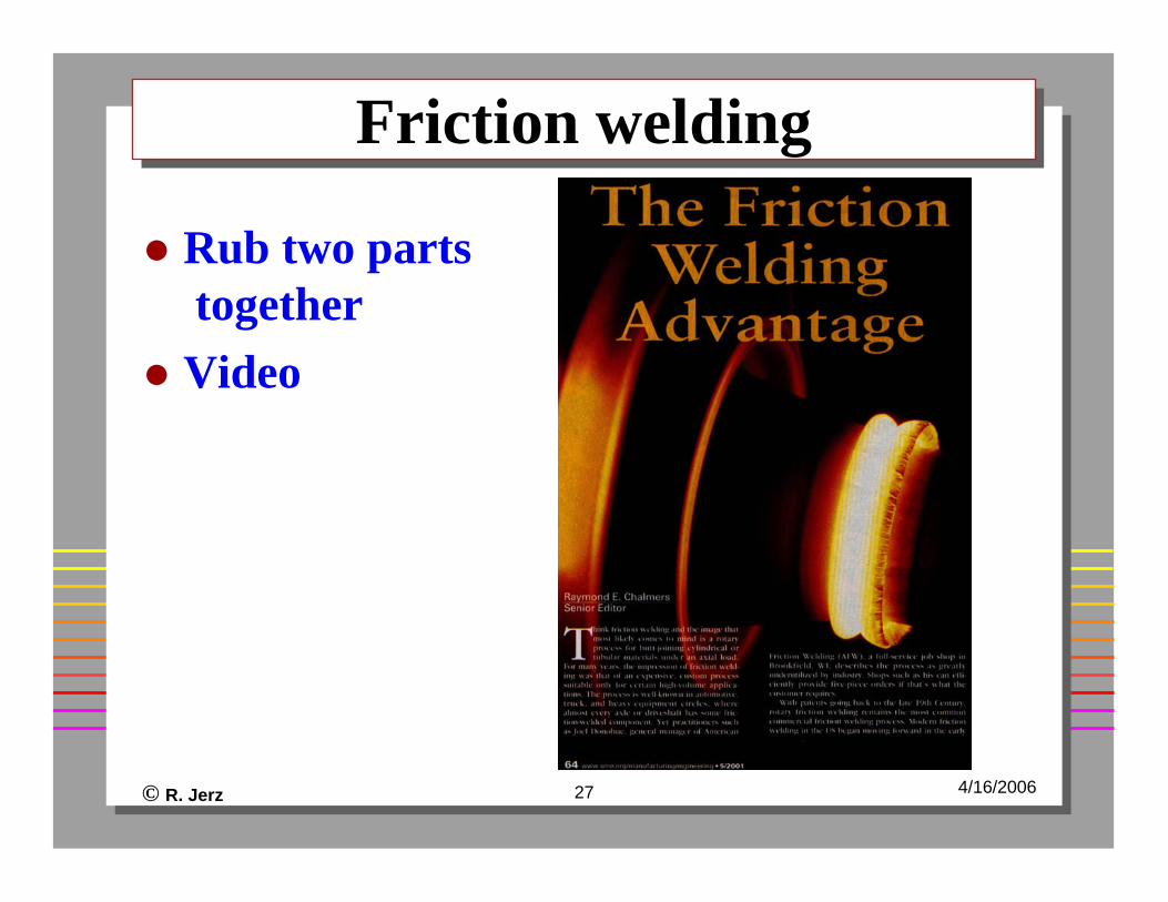
Friction weldingFriction welding
Rub two partstogetherVideo

© R. Jerz 28 4/16/2006
Figure 31.6 (a) Sequence of events in resistance spot welding. (b) Cross-section of a spot weld, showing the weld nugget and the indentation of the electrode on the sheet surfaces. This is one of the most commonly used processes in sheet-metal fabrication and in automotive-body assembly.
Resistance (Spot) Welding (RW)Resistance (Spot) Welding (RW)

© R. Jerz 29 4/16/2006
Resistance WeldingResistance Welding
VideoSpot, projection, and seamHeating• H=I2RT, where• I=current• R=electrical resistance• T=time

© R. Jerz 30 4/16/2006
Figure 31.7 (a) Schematic illustration of an air-operated, rocker-arm, spot welding machine. (b) and (c) Two electrode designs for easyaccess into components to be welded.
Spot Welding EquipmentSpot Welding Equipment

© R. Jerz 31 4/16/2006
Figure 31.13 (a) Schematic illustration of resistance projection welding. (b) A welded bracket. (c) and (d) Projection welding of nuts or threaded bosses and studs. (e) Resistance-projection-welded grills.
Resistance Projection WeldingResistance Projection Welding

© R. Jerz 32 4/16/2006
Figure 31.10 Test methods for spot welds: (a) tension-shear test, (b) cross-tension test, (c) twist test, (d) peel test. (see also Fig. 32.9).
Spot Weld TestingSpot Weld Testing

© R. Jerz 33 4/16/2006
Brazing & SolderingBrazing & Soldering
VideoFiller materialTemperature below melting point of metalsDifferences from welding• brazing alloy• strength of brazing alloy• capillary action
Soldering - lower temperature than brazing

© R. Jerz 34 4/16/2006
Joint Designs used in BrazingJoint Designs used in Brazing
Figure 32.3 Joint designs commonly used in brazing operations. The clearance between the two parts being brazed in an important factor in joint strength. If the clearance is too small, the molten braze metal will not penetrate the interface fully. If it is too large, there will be insufficient capillary action for the molten metal to fill the interface.

© R. Jerz 35 4/16/2006
JointsJoints
Should be cleanShould have close tolerance

© R. Jerz 36 4/16/2006
Advantages of BrazingAdvantages of Brazing
Join a variety of metalsQuickLow temperatureAutomation is possible

© R. Jerz 37 4/16/2006
AdhesivesAdhesives

© R. Jerz 38 4/16/2006
AdhesivesAdhesives
Epoxies - most are 2 componentsCyanoacrylates - “super glues”Anaerobics• one component, cure when oxygen is removed
Acrylics• catalyst primer and adhesive
Urethanes• low temperatures
Silicones - flexible jointsHot melts

© R. Jerz 39 4/16/2006
Advantages & DisadvantagesAdvantages & Disadvantages
Combination of materialsLow temperatureJoining of thin materialsJoining of heat sensitive materialsInexpensiveLess assembly timeUnstable at higher temperatureDestructive testing requiredSurface preparationCure time

© R. Jerz 40 4/16/2006
Design for Assembly (DFM)Design for Assembly (DFM)
Many ideasFunctionCostTimeDFM Video

© R. Jerz 41 4/16/2006
DFM - ConceptsDFM - Concepts
Reduce the number of partsReduce number of fastenersUse modular designsReduce need to handle several components at the same timeLimit number of directionsUse high quality componentsDesign fasteners that can be easily automatically feed

© R. Jerz 42 4/16/2006
DFM ExamplesDFM Examples