jmacfiles.s3.amazonaws.com...testing: lock operation and condition of battery (or battery...
TRANSCRIPT

INS-230D/PM Page 1
Detex Corporation, 302 Detex Drive, New Braunfels, Texas 78130-3045(830)629-2900 / 1-800-729-3839 / Fax (830)620-6711
E-MAIL: [email protected] INTERNET: www.detex.com
INSTALLATION INSTRUCTIONS FOR THE ECL-230D/230D-PH EXIT CONTROL LOCK
INS-230D/PM July 3, 2008
SIREN SWITCH ASSEMBLY
PROBLEMS?

INS-230D/PM Page 2

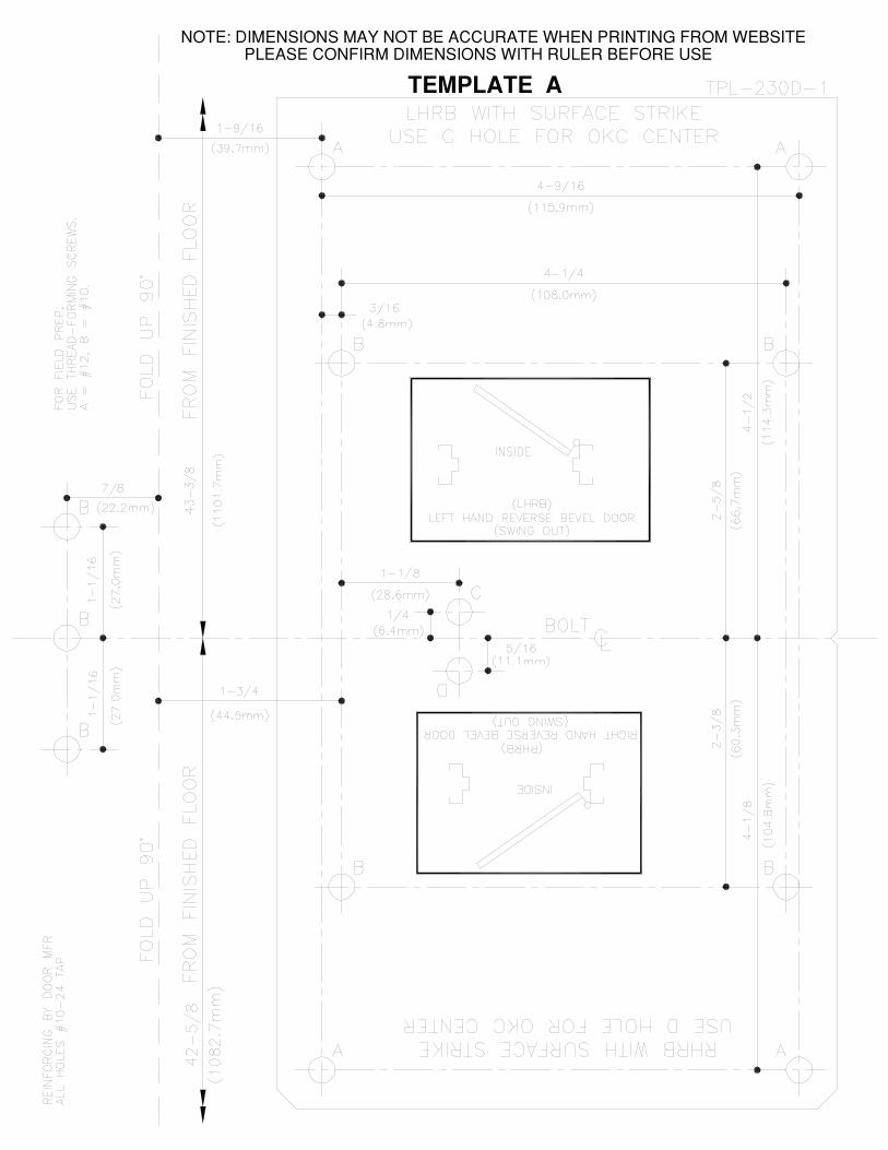
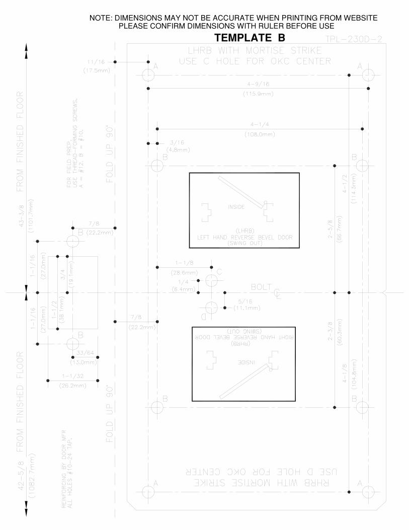
TWO TEMPLATES ARE PROVIDED. SELECT THE PROPER ONE, MORTISE OR SURFACE STRIKE, ANDFOLD ALONG DASHED LINE MARKED 'FOLD UP 90°'.
DRAW A LINE ON THE DOOR, FOR CENTERLINE OF BOLT. HEIGHT OF THIS LINE FROM FINISHEDFLOOR AS SHOWN ON THE TEMPLATE IS 43-3/8" FOR LHR & 42-5/8" FOR RHR.BUTT THE DOOR FIRMLY AGAINST THE DOOR STOP. POSITION THE TEMPLATE ON THE DOOR.
MARK THE 4 HOLES MARKED 'A' AND THE 4 HOLES MARKED 'B' ON THE DOOR.MARK THE 'B' HOLES ON THE FRAME: 2 HOLES FOR MORTISE STRIKE OR 3 HOLES FOR SURFACESTRIKE.
IF THE OKC IS TO BE INSTALLED, MARK THE OKC HOLE CENTER, AT 'C' FOR LHR OR 'D' FOR RHR.BORE A HOLE THROUGH THE DOOR FOR THE RIM CYLINDER. (1-1/4" DIA FOR THE DETEX CYLINDER).DRILL DOOR HOLES MARKED 'A' (#18 DRILL) FOR 5.5MM SCREWS.DRILL DOOR HOLES MARKED 'B' (#25 DRILL) FOR 4.8MM SCREWS.DRILL FRAME HOLES MARKED 'B' FOR #10 SCREWS.INSTALL THE STRIKE WITH #10 SCREWS.
*TO REMOVE COVER FROM DEVICE, TURN COVER LOCK KEY COUNTERCLOCKWISE(CCW) 8 TURNS
REMOVE KEY, ALIGN TIMING MARKS AND INSERT CYLINDER.
INSTALL 1 SCREW AND LOCKWASHER IN THE EXPOSED HOLE.
INSERT THE KEY AND TURN IT TO EXPOSE THE SECOND HOLE.
INSTALL THE SECOND SCREW AND LOCKWASHER.
TURN THE KEY IN BOTH DIRECTIONS. THERE MUST NOT BE ANY FRICTION OR BINDING.
SECURING THE CYLINDER:
VERIFYING TAILPIECE LENGTH:
FIG. A- OUTSIDE KEY CONTROL (OKC) INSTALLATION
INSIDE KEY CONTROL (IKC) INSTALLATIONCYLINDER / TAILPIECE PREPARATION
INS-230D/PM Page 3
WITH KEY REMOVED,TIMING MARKSSHOULD BE ALIGNED
NOTE: DO NOT REMOVE THE PUSH NUT

NOTE:
INS-230D/PM Page 4
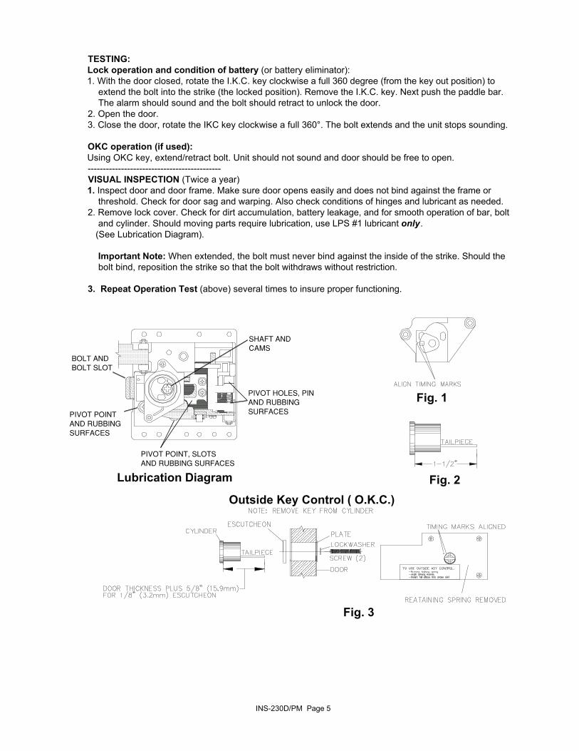
TESTING:Lock operation and condition of battery (or battery eliminator):1. With the door closed, rotate the I.K.C. key clockwise a full 360 degree (from the key out position) to extend the bolt into the strike (the locked position). Remove the I.K.C. key. Next push the paddle bar. The alarm should sound and the bolt should retract to unlock the door.2. Open the door.3. Close the door, rotate the IKC key clockwise a full 360°. The bolt extends and the unit stops sounding.
OKC operation (if used):Using OKC key, extend/retract bolt. Unit should not sound and door should be free to open.--------------------------------------------VISUAL INSPECTION (Twice a year)1. Inspect door and door frame. Make sure door opens easily and does not bind against the frame or threshold. Check for door sag and warping. Also check conditions of hinges and lubricant as needed.2. Remove lock cover. Check for dirt accumulation, battery leakage, and for smooth operation of bar, bolt and cylinder. Should moving parts require lubrication, use LPS #1 lubricant only. (See Lubrication Diagram).
Important Note: When extended, the bolt must never bind against the inside of the strike. Should the bolt bind, reposition the strike so that the bolt withdraws without restriction.
3. Repeat Operation Test (above) several times to insure proper functioning.
Lubrication Diagram
Fig. 1
Fig. 2
Fig. 3
INS-230D/PM Page 5
Outside Key Control ( O.K.C.)

TROUBLESHOOTING1. Siren does not sound when the paddle bar is pushed: A) Remove the cover by inserting the cover key and turning it counter-clockwise approximately 6-8 complete turns. B) Disengage the cover from the back plate and swing it out of the way. C) Confirm the battery is good visually and the voltage is a minimum of 7 volts. If OK continue. If not replace the battery and check for broken wires and retest. If unit is still not sounding call DETEX Customer Service in USA at 1-800-729-3839.2. Key control cylinder (IKC) - Hard to turn (Binding): A) Make sure the cover key is available. B) Push on the paddle bar to open the door - with the door open, reset alarm. C) Keeping the door open, use the key to turn the control cylinder (IKC) key clockwise and counter-clockwise. Bolt should extend and retract freely. D) If the bolt and key worked freely, the problem is alignment between the bolt and the keeper/strike. E) If step "B" does not conform, remove the cover (see step 1A & 1B). F) Remove the cylinder housing (Cam bridge Assembly). With the key removed, confirm the timing markings (Fig. 1). G) If the timing marks do not line up then reinstall the cylinder (per instructions). H) If the cylinder turns hard, the tail piece is too long and needs to be cut as Fig. 2. Fig. 2 denotes Detex cylinder ECL-445, 5 pin. For 6-7 pin rim cylinder use ECL-1595 escutcheon and cut tailpiece accordingly. I) Insert the key in the cylinder and turn it clockwise/counter-clockwise. The cam and the key should turn freely. If the key turns, but not the cam, the cylinder tail piece was cut too short and has slipped out of the cam. Replace the tailpiece or the cylinder (Fig. 2).
3. The bolt does not retract/extend using the outside key control (OKC): A) Remove the unit from the door. B) From the rear side of the casting, confirm the retaining spring was removed (Fig. 3). C) Confirm the OKC shaft/cam is not broken and the push nut is in place. D) Confirm the tailpiece length is 5/8" beyond the door or beyond the reinforcing plate (Fig. 3). E) Confirm the index mark alignment (Fig 3). F) While the unit is off the door, check the OKC operations. Using a screw driver, turn the cam clockwise/counter-clockwise. G) Retract the bolt, align the index marks, remove key, re-install the lock body (make sure the alignment mark does not move when reinstalling the lock body). Be sure the cylinder tailpiece is engaging the cross slot on the cam (Fig. 3).
4. Siren continues to sound after resetting the alarm (Bolt extended): A) Retract the bolt B) Remove the cover (see step 1A & 1B). C) Disconnect the battery D) Identify the screws holding the Cam Bridge and remove the screws and Cam Bridge. Inspect switch levers. Make sure switch levers are not damaged or missing. E) If siren still continues to sound after resetting the alarm call Detex Customer Service Department at 1-800-729-3839.
INS-230D/PM Page 6