jet siphon flowtests - big water siphon flowtests.pdfthe 6-inch task force tips low-level strainer...
TRANSCRIPT
2012 GBW Associates, LLC, Westminster, MD
Jet Siphon
Flow Performance Tests
Conducted by:
GBW Associates, LLC
July 7, 2012
Ashville, Pennsylvania

Jet Siphon Flow Tests July 7, 2012
2012 GBW Associates, LLC, Westminster, MD
Contents
Scope of Project 1
Test Site 1
Pumper Used 2
Test Gauges Used 2
Suction Hose Used for Water Transfer 3
Jet Siphons Tested 4
The Test Layout 11
Testing Procedure 16
Test Results 18
Summary 29
◊ ◊ ◊
Jet Siphon Flow Tests July 7, 2012
2012 GBW Associates, LLC, Westminster, MD Page 1
Scope of Project
On July 7, 2012, GBW Associates, LLC conducted a series of tests on various
types of “jet siphon” water transfer devices. The tests were conducted in Cambria
County, Pennsylvania, at a PennDOT facility located just outside the Borough of
Ashville on State Route 53. Mark Davis, President of GBW Associates, LLC
served as the project coordinator and data analyst. Chief Joe Racz and several
members from the Ashville Volunteer Fire Company partnered with GBW
Associates to provide a pumper and manpower to support the testing process.
The scope of the project was threefold:
• Evaluate the water transfer capabilities of various jet siphon devices;
• Evaluate what pump discharge pressure provides the optimum
performance for the tested jet siphons devices; and,
• Evaluate the flow difference between using 1-1/2-inch and 1-3/4-inch
hose as the supply feed for the individual jet siphon devices.
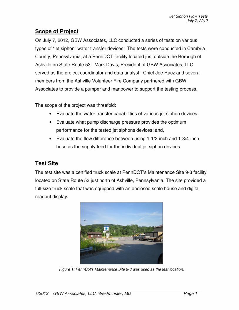
Test Site
The test site was a certified truck scale at PennDOT’s Maintenance Site 9-3 facility
located on State Route 53 just north of Ashville, Pennsylvania. The site provided a
full-size truck scale that was equipped with an enclosed scale house and digital
readout display.
Figure 1: PennDot’s Maintenance Site 9-3 was used as the test location.
Jet Siphon Flow Tests July 7, 2012
2012 GBW Associates, LLC, Westminster, MD Page 2
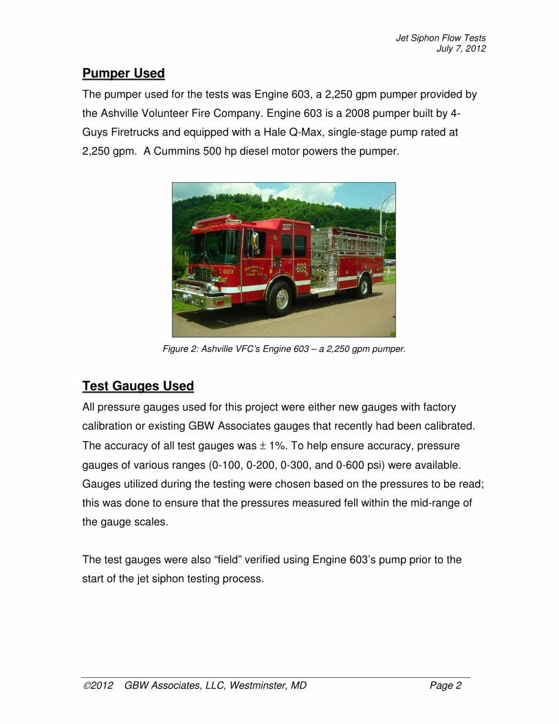
Pumper Used
The pumper used for the tests was Engine 603, a 2,250 gpm pumper provided by
the Ashville Volunteer Fire Company. Engine 603 is a 2008 pumper built by 4-
Guys Firetrucks and equipped with a Hale Q-Max, single-stage pump rated at
2,250 gpm. A Cummins 500 hp diesel motor powers the pumper.
Figure 2: Ashville VFC’s Engine 603 – a 2,250 gpm pumper.
Test Gauges Used
All pressure gauges used for this project were either new gauges with factory
calibration or existing GBW Associates gauges that recently had been calibrated.
The accuracy of all test gauges was ± 1%. To help ensure accuracy, pressure
gauges of various ranges (0-100, 0-200, 0-300, and 0-600 psi) were available.
Gauges utilized during the testing were chosen based on the pressures to be read;
this was done to ensure that the pressures measured fell within the mid-range of
the gauge scales.
The test gauges were also “field” verified using Engine 603’s pump prior to the
start of the jet siphon testing process.

Jet Siphon Flow Tests July 7, 2012
2012 GBW Associates, LLC, Westminster, MD Page 3
Figure 3: Field verification of the test gauges was done prior to starting the flow testing of jet siphon devices. All three gauges displayed 100 psi during this static pressure test – thus verifying calibration.
Suction Hose Used for Water Transfer
The Ashville Volunteer Fire Company provided the suction hose used for the flow
tests. Three different suction hose sizes were used based upon the size of the jet
siphon device being tested. The following suction hose was used for the flow
tests:
Table 1: Suction Hose Used
Manufacturer Diameter Length
Firequip 4-1/2-inches 8-feet
Kochek 5-inches 13-feet
Firequip 6-inches 14-feet
All suction hose was inspected and found to be free of defects and in good
operating condition.
It is important to note that the varying lengths of suction hose was due to the
practice of purchasing suction hose length based upon the length that will fit on the
fire department’s pumpers.
Jet Siphon Flow Tests July 7, 2012
2012 GBW Associates, LLC, Westminster, MD Page 4
Jet Siphons Tested
Seven jet siphon devices were flow tested – three “homemade” ones and four
“manufactured” ones. The three homemade devices were jet siphons only – they
had no secondary use. Three of the four manufactured devices were low-level
suction strainers with built-in jet siphons.
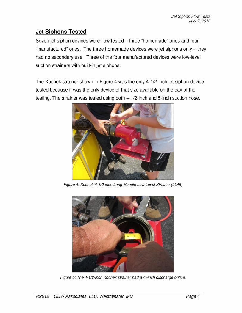
The Kochek strainer shown in Figure 4 was the only 4-1/2-inch jet siphon device
tested because it was the only device of that size available on the day of the
testing. The strainer was tested using both 4-1/2-inch and 5-inch suction hose.
Figure 4: Kochek 4-1/2-inch Long-Handle Low Level Strainer (LL45)
Figure 5: The 4-1/2-inch Kochek strainer had a ¾-inch discharge orifice.
Jet Siphon Flow Tests July 7, 2012
2012 GBW Associates, LLC, Westminster, MD Page 5
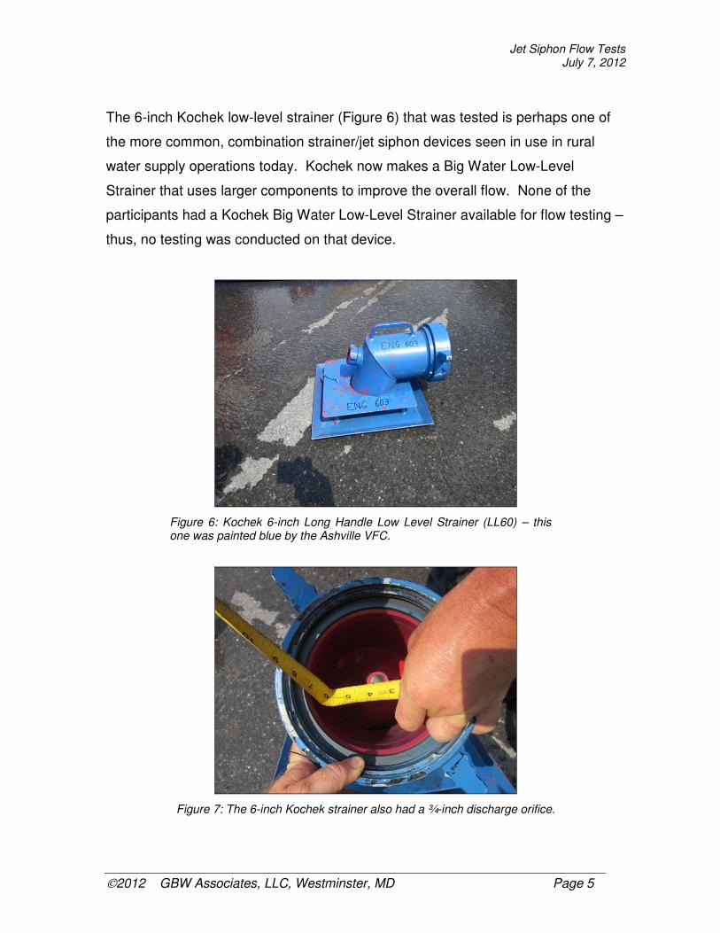
The 6-inch Kochek low-level strainer (Figure 6) that was tested is perhaps one of
the more common, combination strainer/jet siphon devices seen in use in rural
water supply operations today. Kochek now makes a Big Water Low-Level
Strainer that uses larger components to improve the overall flow. None of the
participants had a Kochek Big Water Low-Level Strainer available for flow testing –
thus, no testing was conducted on that device.
Figure 6: Kochek 6-inch Long Handle Low Level Strainer (LL60) – this one was painted blue by the Ashville VFC.
Figure 7: The 6-inch Kochek strainer also had a ¾-inch discharge orifice.
Jet Siphon Flow Tests July 7, 2012
2012 GBW Associates, LLC, Westminster, MD Page 6
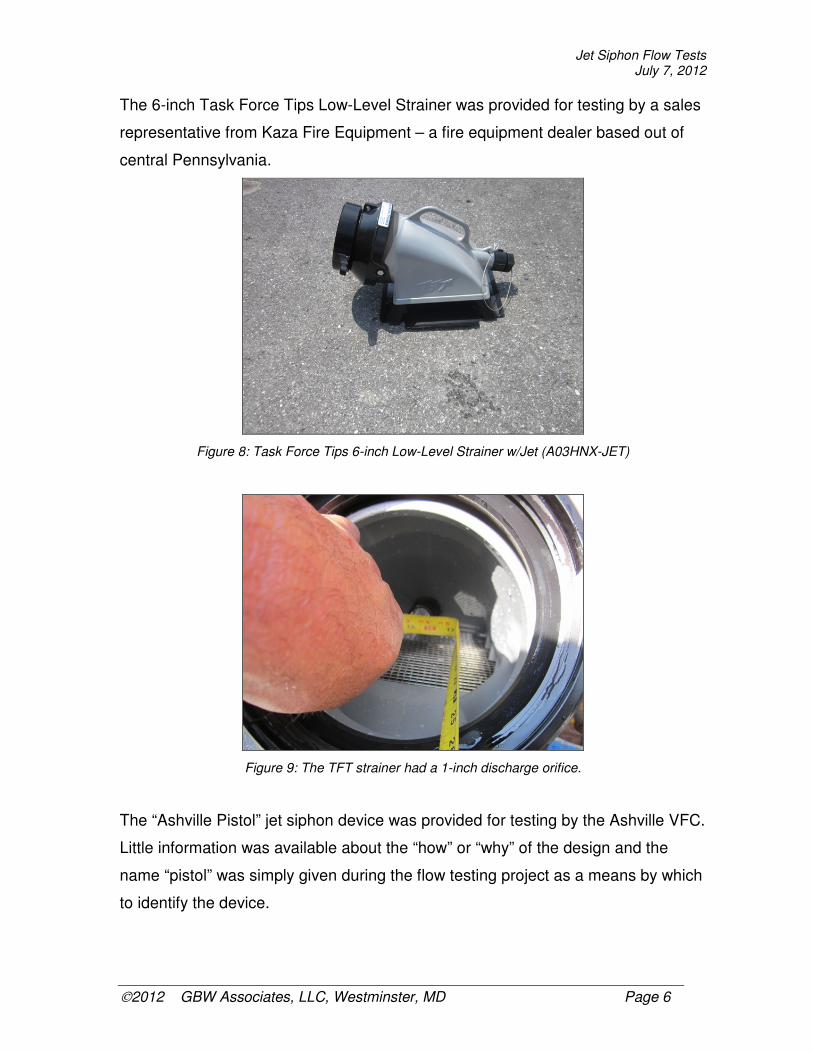
The 6-inch Task Force Tips Low-Level Strainer was provided for testing by a sales
representative from Kaza Fire Equipment – a fire equipment dealer based out of
central Pennsylvania.
Figure 8: Task Force Tips 6-inch Low-Level Strainer w/Jet (A03HNX-JET)
Figure 9: The TFT strainer had a 1-inch discharge orifice.
The “Ashville Pistol” jet siphon device was provided for testing by the Ashville VFC.
Little information was available about the “how” or “why” of the design and the
name “pistol” was simply given during the flow testing project as a means by which
to identify the device.

Jet Siphon Flow Tests July 7, 2012
2012 GBW Associates, LLC, Westminster, MD Page 7
The unique feature of the pistol jet siphon is that is does not thread onto the
suction hose – it is held in place by a strap. This design allows the pistol to be
used on different size diameter suction hose.
Figure 10: “The Ashville Pistol” (Homemade – Ashville VFC)
Figure 11: The Pistol had a 1-inch discharge orifice.
Like the Pistol, the “Blue Thread-On” jet siphon device was also homemade by a
member of the Ashville VFC. And also like the Pistol, little information was
available concerning the design of the device. The Blue Thread-On jet siphon is
designed to attach to the male end of a 6-inch suction hose.

Jet Siphon Flow Tests July 7, 2012
2012 GBW Associates, LLC, Westminster, MD Page 8
Figure 12: “Ashville Blue 6” Thread-On” (Homemade by Ashville VFC)
Figure 13: This jet siphon uses a very simple and unique design.
Jet Siphon Flow Tests July 7, 2012
2012 GBW Associates, LLC, Westminster, MD Page 9
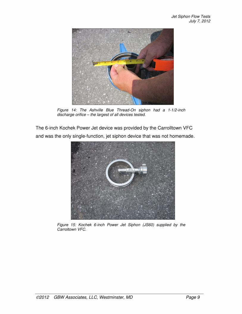
Figure 14: The Ashville Blue Thread-On siphon had a 1-1/2-inch discharge orifice – the largest of all devices tested.
The 6-inch Kochek Power Jet device was provided by the Carrolltown VFC
and was the only single-function, jet siphon device that was not homemade.
Figure 15: Kochek 6-inch Power Jet Siphon (JS60) supplied by the Carroltown VFC.

Jet Siphon Flow Tests July 7, 2012
2012 GBW Associates, LLC, Westminster, MD Page 10
Figure 16: The Kochek Power Jet Siphon had a ¾-inch discharge orifice.
The Dods 6-inch Thread-In device was made by Greg Dods, Vice President of
GBW Associates, LLC and Training Officer for the Winfield Community VFD in
Sykesville, Maryland. The jet siphon threads into the female end of a 6-inch
suction hose.
Figure 17: “Dods 6” Thread-In” (Homemade by Greg Dods, GBW Associates, LLC)

Jet Siphon Flow Tests July 7, 2012
2012 GBW Associates, LLC, Westminster, MD Page 11
Figure 18: The Dods Thread-In had a 1-inch discharge orifice.
The Test Layout
The test layout involved the use of two, portable dump tanks; a pumper; two
lengths of suction hose; two lengths of attack line hose to feed the jet siphons; and
test gauges and pressure measuring equipment.
One, 3,000-gallon portable dump tank (Supply Tank) was set-up immediately
adjacent to the truck scale and Engine 603 positioned to draft out of that tank using
a single length of 6-inch suction hose. This dump tank was used as the supply
source for the water transfer process: it was not situated on the scale and its
contents were not measured at any time during the testing process.
A second, 3,000-gallon portable dump tank (Collection Tank) was set-up on the
truck scale and was used to collect the water that was transferred during each flow
test. This dump tank was where all contents were measured in terms of water
quantity and flows transferred from the Supply Tank.
Because the Collection Tank was larger than the surface of the scale, wood planks
and plywood were used to build a platform on the scale so that the tank was fully
supported without touching the scale’s stationary sides.

Jet Siphon Flow Tests July 7, 2012
2012 GBW Associates, LLC, Westminster, MD Page 12
The test suction hose and test jet siphon were placed in the Supply Tank and
positioned to discharge water into the Collection Tank. A 50 ft length of attack line
hose was used to supply the test jet siphon and an in-line test gauge was attached
to the jet siphon’s supply inlet. An in-line gauge was also placed on the pump
discharge that was supplying the hose feeding the test jet siphon.
A second length of suction hose equipped with a jet siphon (non-test siphon) was
placed in the Collection Tank and positioned to discharge water back into the
Supply Tank once each flow test was complete. A 50 ft length of attack line hose
was used to supply this water transfer set up.
Figure 19: Diagram of test layout.
Jet Siphon Flow Tests July 7, 2012
2012 GBW Associates, LLC, Westminster, MD Page 13
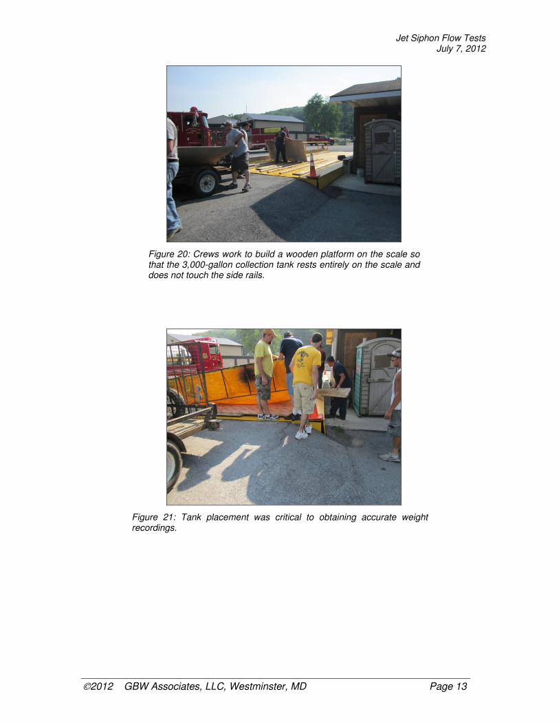
Figure 20: Crews work to build a wooden platform on the scale so that the 3,000-gallon collection tank rests entirely on the scale and does not touch the side rails.
Figure 21: Tank placement was critical to obtaining accurate weight recordings.

Jet Siphon Flow Tests July 7, 2012
2012 GBW Associates, LLC, Westminster, MD Page 14
Figure 22: With the Collection Tank in position on the scale, the 3,000-gallon Supply Tank (foreground) was placed.
Figure 23: Scale readings were displayed digitally inside the scale house and were recorded in an Excel spreadsheet for later analysis.
Jet Siphon Flow Tests July 7, 2012
2012 GBW Associates, LLC, Westminster, MD Page 15
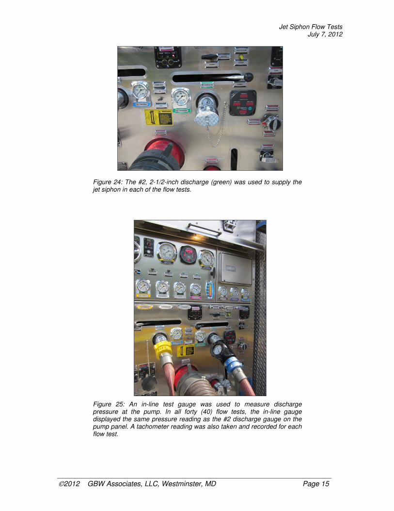
Figure 24: The #2, 2-1/2-inch discharge (green) was used to supply the jet siphon in each of the flow tests.
Figure 25: An in-line test gauge was used to measure discharge pressure at the pump. In all forty (40) flow tests, the in-line gauge displayed the same pressure reading as the #2 discharge gauge on the pump panel. A tachometer reading was also taken and recorded for each flow test.
Jet Siphon Flow Tests July 7, 2012
2012 GBW Associates, LLC, Westminster, MD Page 16
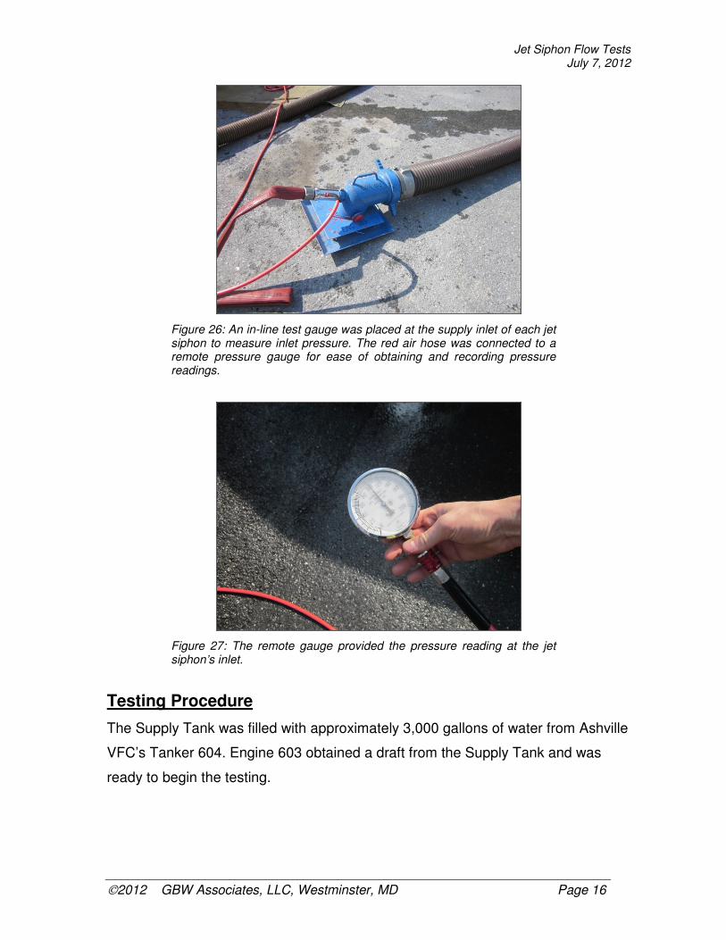
Figure 26: An in-line test gauge was placed at the supply inlet of each jet siphon to measure inlet pressure. The red air hose was connected to a remote pressure gauge for ease of obtaining and recording pressure readings.
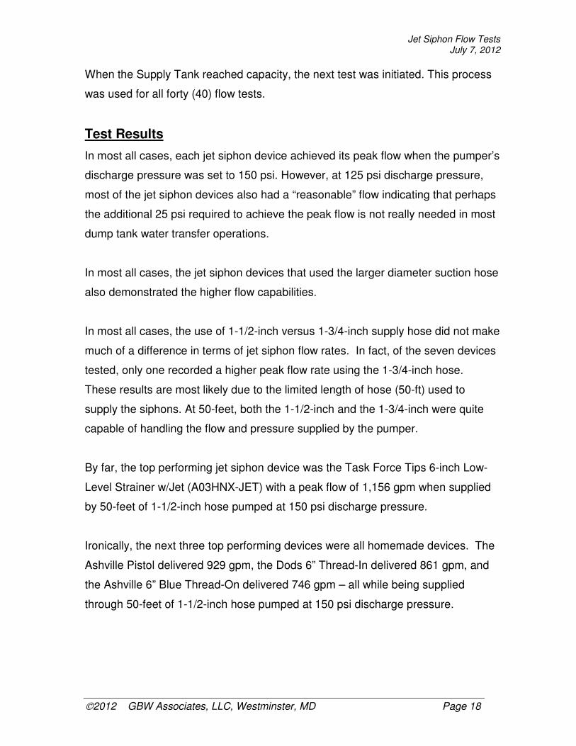
Figure 27: The remote gauge provided the pressure reading at the jet siphon’s inlet.
Testing Procedure
The Supply Tank was filled with approximately 3,000 gallons of water from Ashville
VFC’s Tanker 604. Engine 603 obtained a draft from the Supply Tank and was
ready to begin the testing.

Jet Siphon Flow Tests July 7, 2012
2012 GBW Associates, LLC, Westminster, MD Page 17
For each jet siphon tested, Engine 603’s operator brought the pump to a pre-
established discharge pressure (100 psi, 125 psi, or 150 psi) and waited for the
timekeeper’s signal. In the scale house, a weight reading was taken from the
scale’s digital readout display and recorded in an Excel spreadsheet.
Upon the timekeeper’s signal, Engine 603’s operator opened the discharge and
began pumping to the jet siphon at the pre-determined pressure. Time was
allowed to run for 2.0 or 2.5 minutes before the pump operator was directed to
shut-down the discharge.
(Notes: Test #10 [TFT Low-Level] was only allowed to run for 1.75 minutes
because the transfer rate was so high that the Supply Tank was filled before the
2.0-minute mark was reached. Test #22 [Pistol] was stopped after about 45
seconds because the reaction force on the jet siphon was too great in the 4-1/2-
inch suction hose making for an unsafe condition.)
During the time period that the water transfer process was occurring, pressure
readings were taken at both in-line test gauges (pump discharge and jet siphon
supply) and were recorded on a data collection form.
Once the water transfer was stopped, a second weight reading was taken in the
scale house using the same digital display. The weight reading was recorded in
the Excel spreadsheet and a gallons per minute (gpm) flow rate was calculated as
follows:
(Ending Weight – Starting Weight) / 8.35 lbs / minutes of flow
Once the flow rate calculation was completed, the pump operator was given the
signal to transfer water from the Collection Tank back into the Supply Tank using
the other jet siphon device.
Jet Siphon Flow Tests July 7, 2012
2012 GBW Associates, LLC, Westminster, MD Page 18
When the Supply Tank reached capacity, the next test was initiated. This process
was used for all forty (40) flow tests.
Test Results
In most all cases, each jet siphon device achieved its peak flow when the pumper’s
discharge pressure was set to 150 psi. However, at 125 psi discharge pressure,
most of the jet siphon devices also had a “reasonable” flow indicating that perhaps
the additional 25 psi required to achieve the peak flow is not really needed in most
dump tank water transfer operations.
In most all cases, the jet siphon devices that used the larger diameter suction hose
also demonstrated the higher flow capabilities.
In most all cases, the use of 1-1/2-inch versus 1-3/4-inch supply hose did not make
much of a difference in terms of jet siphon flow rates. In fact, of the seven devices
tested, only one recorded a higher peak flow rate using the 1-3/4-inch hose.
These results are most likely due to the limited length of hose (50-ft) used to
supply the siphons. At 50-feet, both the 1-1/2-inch and the 1-3/4-inch were quite
capable of handling the flow and pressure supplied by the pumper.
By far, the top performing jet siphon device was the Task Force Tips 6-inch Low-
Level Strainer w/Jet (A03HNX-JET) with a peak flow of 1,156 gpm when supplied
by 50-feet of 1-1/2-inch hose pumped at 150 psi discharge pressure.
Ironically, the next three top performing devices were all homemade devices. The
Ashville Pistol delivered 929 gpm, the Dods 6” Thread-In delivered 861 gpm, and
the Ashville 6” Blue Thread-On delivered 746 gpm – all while being supplied
through 50-feet of 1-1/2-inch hose pumped at 150 psi discharge pressure.

Jet Siphon Flow Tests July 7, 2012
2012 GBW Associates, LLC, Westminster, MD Page 19
Table 2: Peak Performances @ 150 psi Discharge Pressure
Device Supply Hose
Suction Hose
Pump Discharge
Peak Transfer Rate
TFT 6” Low Level 1-1/2-inch 6-inch 150 psi 1,156 gpm Ashville Pistol 1-1/2-inch 6-inch 150 psi 929 gpm Dods 6” Thread-In 1-1/2-inch 6-inch 150 psi 861 gpm Ashville Blue 6” Thread-On 1-1/2-inch 6-inch 150 psi 746 gpm Kochek 6” Power Jet 1-1/2-inch 6-inch 150 psi 641 gpm Kochek 4-1/2” Low Level 1-3/4-inch 5-inch 150 psi 556 gpm Kochek 6” Low Level 1-1/2-inch 6-inch 150 psi 539 gpm
Table 3: Peak Performances @ 125 psi Discharge Pressure
Device Supply Hose
Suction Hose
Pump Discharge
Peak Transfer Rate
TFT 6” Low Level 1-3/4-inch 6-inch 125 psi 905 gpm Ashville Pistol 1-1/2-inch 6-inch 125 psi 827 gpm Dods 6” Thread-In 1-1/2-inch 6-inch 125 psi 770 gpm Ashville Blue 6” Thread-On 1-1/2-inch 6-inch 125 psi 651 gpm Kochek 6” Power Jet 1-1/2-inch 6-inch 125 psi 576 gpm Kochek 4-1/2” Low Level 1-3/4-inch 5-inch 125 psi 505 gpm Kochek 6” Low Level 1-3/4-inch 6-inch 125 psi 488 gpm
Table 4: Peak Performances @ 100 psi Discharge Pressure
Device Supply Hose
Suction Hose
Pump Discharge
Peak Transfer Rate
TFT 6” Low Level 1-3/4-inch 6-inch 100 psi 839 gpm Ashville Pistol 1-1/2-inch 6-inch 100 psi 718 gpm Dods 6” Thread-In 1-1/2-inch 6-inch 100 psi 653 gpm Ashville Blue 6” Thread-On 1-1/2-inch 6-inch 100 psi 568 gpm Kochek 6” Power Jet 1-1/2-inch 6-inch 100 psi 445 gpm Kochek 6” Low Level 1-3/4-inch 6-inch 100 psi 472 gpm Kochek 4-1/2” Low Level 1-3/4-inch 5-inch 100 psi 433 gpm

Jet Siphon Flow Tests July 7, 2012
2012 GBW Associates, LLC, Westminster, MD Page 20
Figure 28: Each jet siphon was outfitted with the in-line test gauge before being placed in the Supply Tank. In this photo, the 6-inch Kochek Low-Level strainer is ready for testing.
Figure 29: The jet siphon device is in position in the Supply Tank for testing.

Jet Siphon Flow Tests July 7, 2012
2012 GBW Associates, LLC, Westminster, MD Page 21
Figure 30: A “tare” weight was recorded in the scale house before water transfer operations were started.
Figure 31: The pump discharge pressure was raised to 100 psi and water transfer operations were started. Subsequent tests were completed with pump discharge pressures set to 125 psi and 150 psi.

Jet Siphon Flow Tests July 7, 2012
2012 GBW Associates, LLC, Westminster, MD Page 22
Figure 32: Water was transferred to the Collection Tank.
Figure 33: A pressure reading was recorded on the in-line test gauge located at the jet siphon device’s supply inlet.

Jet Siphon Flow Tests July 7, 2012
2012 GBW Associates, LLC, Westminster, MD Page 23
Figure 34: When the time limit was reached, a second weight recording was taken in the scale house. A flow rate was then calculated using the data collected. In this test of the Kochek 6-inch Low-Level Strainer, a peak performance flow rate of 539 gpm at 150 psi pump discharge pressure was achieved.
Figure 35: The Task Force Tips 6-Inch Low-Level Strainer in position ready for testing.

Jet Siphon Flow Tests July 7, 2012
2012 GBW Associates, LLC, Westminster, MD Page 24
Figure 36: The Task Force Tips device reached its peak performance of 1,156 gpm at 150 psi pump discharge pressure.
Figure 37: The Ashville Pistol being installed on a length of suction hose for testing.
Jet Siphon Flow Tests July 7, 2012
2012 GBW Associates, LLC, Westminster, MD Page 25
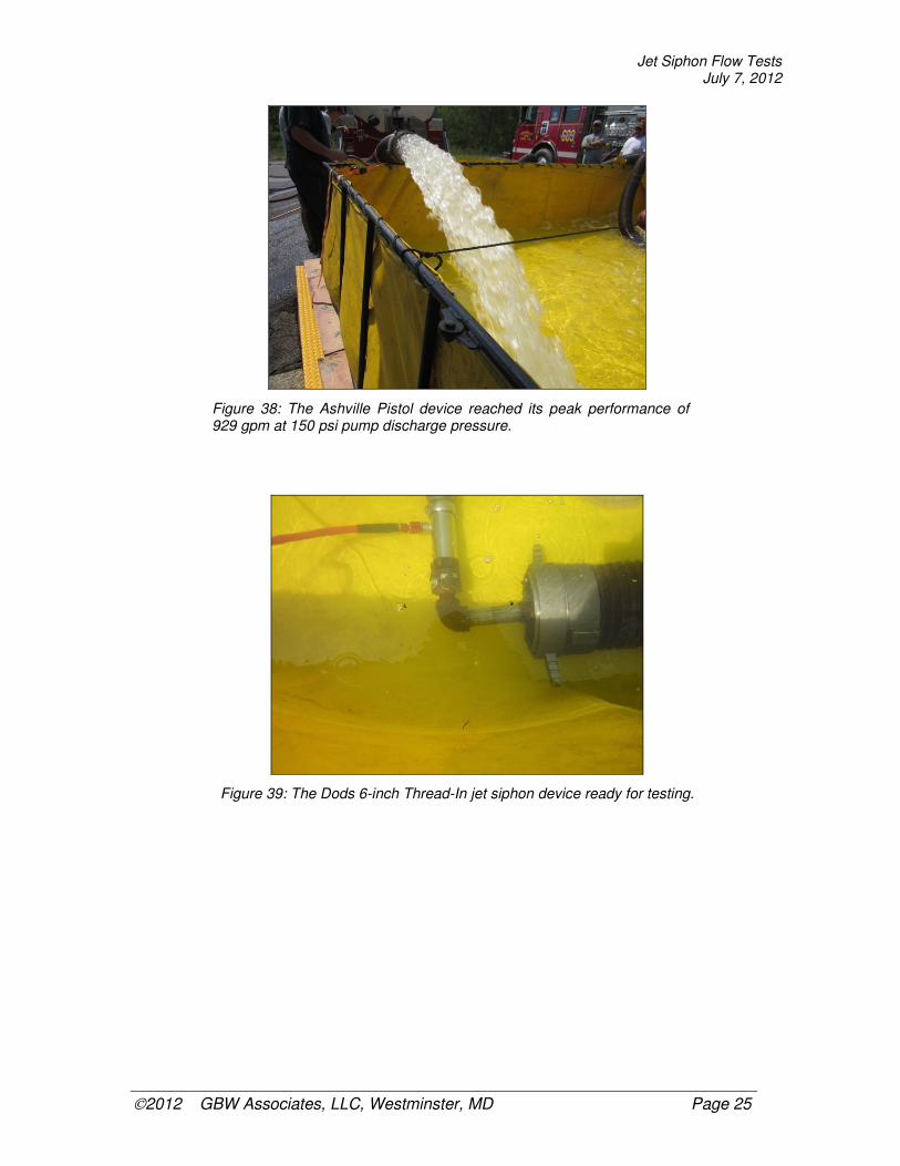
Figure 38: The Ashville Pistol device reached its peak performance of 929 gpm at 150 psi pump discharge pressure.
Figure 39: The Dods 6-inch Thread-In jet siphon device ready for testing.
Jet Siphon Flow Tests July 7, 2012
2012 GBW Associates, LLC, Westminster, MD Page 26
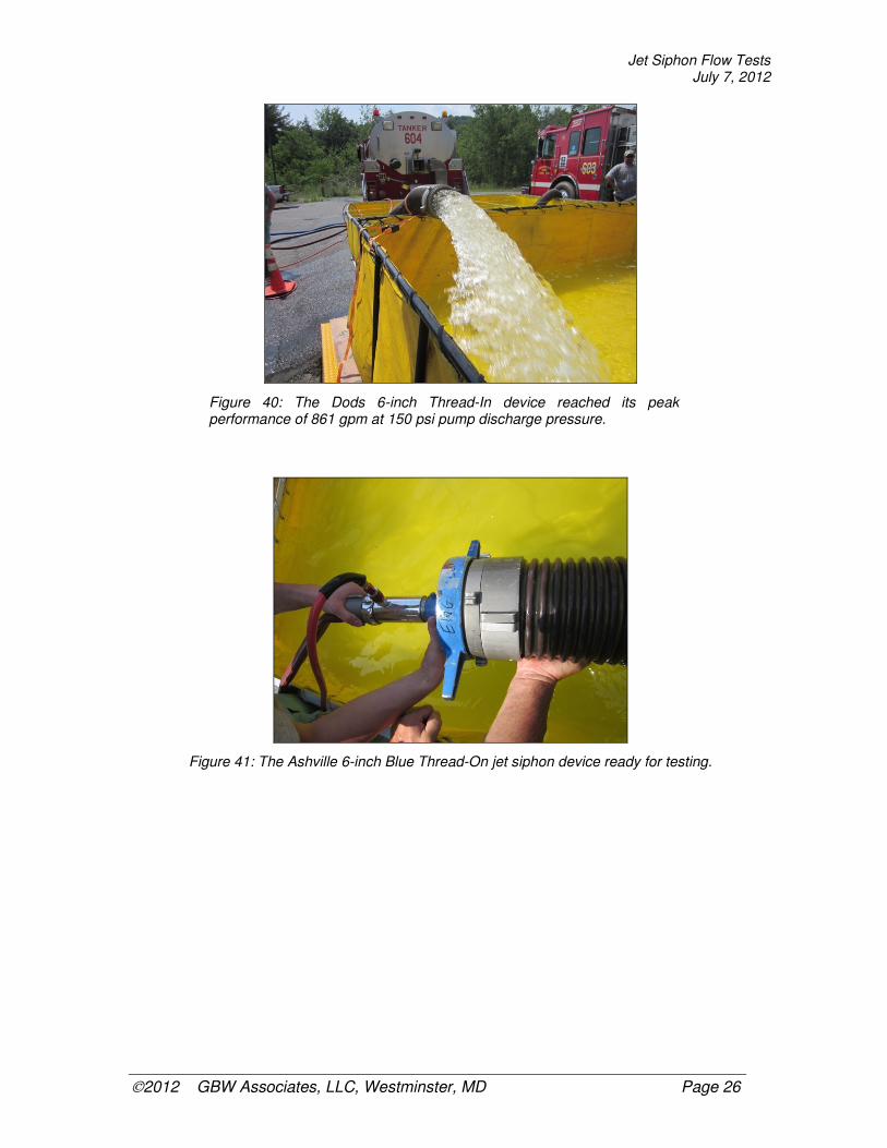
Figure 40: The Dods 6-inch Thread-In device reached its peak performance of 861 gpm at 150 psi pump discharge pressure.
Figure 41: The Ashville 6-inch Blue Thread-On jet siphon device ready for testing.

Jet Siphon Flow Tests July 7, 2012
2012 GBW Associates, LLC, Westminster, MD Page 27
Figure 42: The Ashville 6-inch Blue Thread-On device reached its peak performance of 746 gpm at 150 psi pump discharge pressure.
Figure 43: The Kochek 6-inch Power Jet ready for testing.

Jet Siphon Flow Tests July 7, 2012
2012 GBW Associates, LLC, Westminster, MD Page 28
Figure 44: The Kochek 6-inch Power Jet reached its peak performance of 641 gpm at 150 psi pump discharge pressure.
Figure 45: The Kochek 4-1/2-inch Low-Level Strainer ready for testing.
Jet Siphon Flow Tests July 7, 2012
2012 GBW Associates, LLC, Westminster, MD Page 29
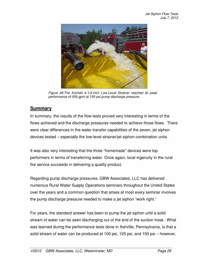
Figure 46:The Kochek 4-1/2-inch Low-Level Strainer reached its peak performance of 556 gpm at 150 psi pump discharge pressure.
Summary
In summary, the results of the flow tests proved very interesting in terms of the
flows achieved and the discharge pressures needed to achieve those flows. There
were clear differences in the water transfer capabilities of the seven, jet siphon
devices tested – especially the low-level strainer/jet siphon combination units.
It was also very interesting that the three “homemade” devices were top
performers in terms of transferring water. Once again, local ingenuity in the rural
fire service succeeds in delivering a quality product.
Regarding pump discharge pressures, GBW Associates, LLC has delivered
numerous Rural Water Supply Operations seminars throughout the United States
over the years and a common question that arises at most every seminar involves
the pump discharge pressure needed to make a jet siphon “work right.”
For years, the standard answer has been to pump the jet siphon until a solid
stream of water can be seen discharging out of the end of the suction hose. What
was learned during the performance tests done in Ashville, Pennsylvania, is that a
solid stream of water can be produced at 100 psi, 125 psi, and 150 psi – however,

Jet Siphon Flow Tests July 7, 2012
2012 GBW Associates, LLC, Westminster, MD Page 30
the resultant flows are quite different – especially with some of the low-level
strainers that have the built-in jet siphon feature. And, in almost every case, the
test data showed that the peak performance occurred at 150 psi pump discharge
pressure.
Because low-level/jet siphon strainers are so popular in rural water supply
operations, the findings of this flow testing project are very important to those
persons who must operate or supervise a multiple, dump tank water supply
operation.
Of some concern is the 150 psi pump discharge pressure needed for peak
performance. The issue really is not so much about the pressure than about the
size of the pump being used at the dump site. Because the use of jet siphons
consumes available pump capacity, pump operators and dump site supervisors
need to be careful not to compromise pumping operations when approaching the
rated capacity of the fire pump (150 psi Net Pump Pressure). This is most
concerning when smaller pumps (1,250 gpm or less) are used to draft from dump
tanks and run jet siphons at the same time.
One approach to consider is to use the lower, 125 psi pump discharge pressure
setting for jet siphon operation. By doing this, more pumping capacity might be
available to overcome friction loss and water demand issues between the dump
site pumper and the attack pumper (or wherever the water is being sent) while still
maintaining a reasonable flow through jet siphon devices.
In terms of the other findings from these performance flow tests, it was clear that
as long as the jet siphon supply lines are kept short (50-feet or less), the use of 1-
1/2-inch or 1-3/4-inch does not seem to make much difference. In addition, it was
also clear that the larger diameter suction hose produces higher transfer flow rates.

Jet Siphon Flow Tests July 7, 2012
2012 GBW Associates, LLC, Westminster, MD Page 31
While the performance flow tests described in this report were not conducted in a
true laboratory setting, every effort was taken to establish constants and controls
so that a fair and reasonable evaluation could be made for each jet siphon device
tested. GBW Associates, LLC believes such evaluations were made and resultant
data reflects the performance of the devices tested that day.
◊ ◊ ◊
A special thanks to Chief Joe Racz and the members of the
Ashville VFC for managing all of the logistics needed to make this
project happen – they did a fantastic job!