jd 9000 - 600f conversion - lankota inc these connectors before proceeding. 11. tee the headsight...
TRANSCRIPT

JD 9000 - 600F Conversion
Combine Manual 09040114a
i
About Headsight Headsight Contact Info Headsight, Inc Bremen, IN 46506 Phone:574-546-5022 Fax: 574-546-5760 Email: [email protected] Web: www.headsight.com
Technical Assistance Phone: 574-220-5511
About this Manual How to use this manual
For new installations, follow all applicable instructions in each of the numbered sections (1,2,etc) in the order that they are presented in this manual. The information in the lettered appendices (A,B, etc) is for service or advanced settings which you will not need for most installations, but may want to reference in the future.
This icon designates information of which you should take note.
This icon designates an important instruction.
Disclaimers Headsight, Insight, Foresight, FeatherSight and TrueSight are trademarks of Headsight, Inc. All other trademarks are property of their respective owners.
Suggestions If you have any suggestions to improve this manual –please call 574-546-5022 or email [email protected].
Portions of this product are protected by US Patents 6202395, 6833299, 7310931, and other US and international patents, issued and pending
ii
Table of Contents About Headsight i
Headsight Contact Info i
Technical Assistance i
About this Manual i
How to use this manual i
Disclaimers i
Suggestions i
1. Installation 1
1.1. Interface Box Mounting 1
1.2. HydraFlex Light Bar 2
1.3. Feeder Harness 3
2. Calibration 4
2.1. Combine Activation (Insight only) 4 2.1.1. Standard Activation: ’91-up DAM (see note) 4 2.1.2. Activation: ’89-‘90 DAM (except as above) 5
2.2. Initialize Insight 6
2.3. Calibrate Insight 6 2.3.1. Sensor Calibration 6
2.4. Combine Contour-Master Calibration 7
3. Settings 8
3.1. Combine Settings 8 3.1.1. Automatic drop rate 8 3.1.2. Hydraulic accumulator 9
4. Operation 10
4.1. Enabling height control 10 4.1.1. 9x00 and 9x10 series 10
4.2. Adjusting header height 11
4.3. Adjusting height sensitivity 11
4.4. Adjusting Float Pressure 12
iii
A Insight Overview 13
1 Rules of menu navigation 13
2 Meaning of the status light 13
3 Screen contrast adjustment 14
4 Resetting Insight™ to defaults 14
5 Updating Insight Software 14
B Advanced Information 16
1 Changing Tilt Orifices 16
2 Connecting the 9 pin T to a 6pin combine Hydro Handle connector 17
C Diagnostics 19
1 Theory of Operation 19
2 Troubleshooting…..by symptom 20
3 Troubleshooting…..common combine problems 24
4 Troubleshooting by Insight error codes 25
5 Reading voltages on the Insight box 29
D Parts 30
1
1. Installation
1.1. Interface Box Mounting
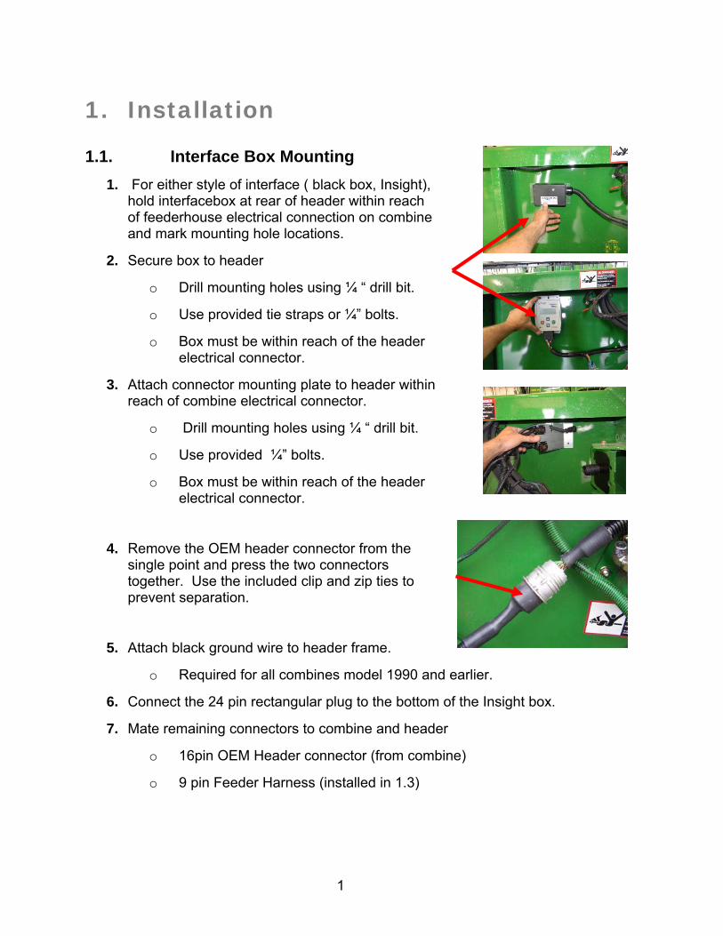
1. For either style of interface ( black box, Insight), hold interfacebox at rear of header within reach of feederhouse electrical connection on combine and mark mounting hole locations.
2. Secure box to header
o Drill mounting holes using ¼ “ drill bit.
o Use provided tie straps or ¼” bolts.
o Box must be within reach of the header electrical connector.
3. Attach connector mounting plate to header within reach of combine electrical connector.
o Drill mounting holes using ¼ “ drill bit.
o Use provided ¼” bolts.
o Box must be within reach of the header electrical connector.
4. Remove the OEM header connector from the single point and press the two connectors together. Use the included clip and zip ties to prevent separation.
5. Attach black ground wire to header frame.
o Required for all combines model 1990 and earlier.
6. Connect the 24 pin rectangular plug to the bottom of the Insight box.
7. Mate remaining connectors to combine and header
o 16pin OEM Header connector (from combine)
o 9 pin Feeder Harness (installed in 1.3)
2
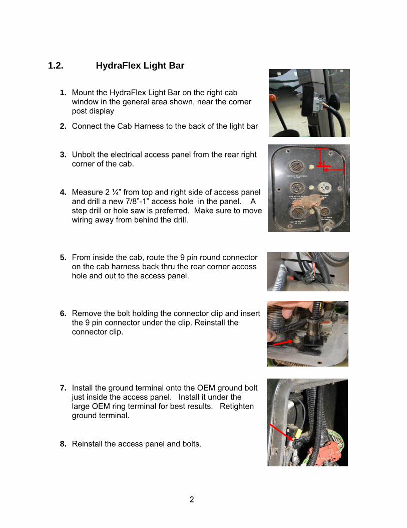
1.2. HydraFlex Light Bar
1. Mount the HydraFlex Light Bar on the right cab window in the general area shown, near the corner post display
2. Connect the Cab Harness to the back of the light bar
3. Unbolt the electrical access panel from the rear right corner of the cab.
4. Measure 2 ¼” from top and right side of access panel and drill a new 7/8”-1” access hole in the panel. A step drill or hole saw is preferred. Make sure to move wiring away from behind the drill.
5. From inside the cab, route the 9 pin round connector on the cab harness back thru the rear corner access hole and out to the access panel.
6. Remove the bolt holding the connector clip and insert the 9 pin connector under the clip. Reinstall the connector clip.
7. Install the ground terminal onto the OEM ground bolt just inside the access panel. Install it under the large OEM ring terminal for best results. Retighten ground terminal.
8. Reinstall the access panel and bolts.
3
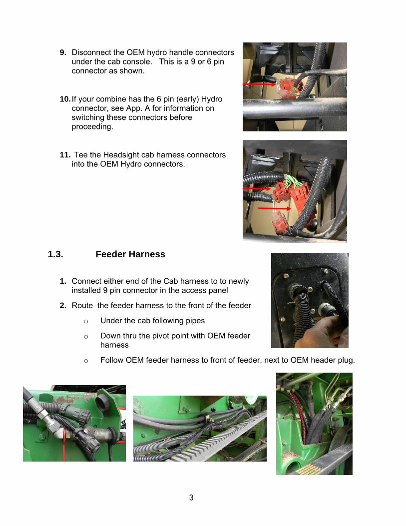
9. Disconnect the OEM hydro handle connectors under the cab console. This is a 9 or 6 pin connector as shown.
10. If your combine has the 6 pin (early) Hydro connector, see App. A for information on switching these connectors before proceeding.
11. Tee the Headsight cab harness connectors into the OEM Hydro connectors.
1.3. Feeder Harness
1. Connect either end of the Cab harness to to newly installed 9 pin connector in the access panel
2. Route the feeder harness to the front of the feeder
o Under the cab following pipes
o Down thru the pivot point with OEM feeder harness
o Follow OEM feeder harness to front of feeder, next to OEM header plug.
4
2. Calibration
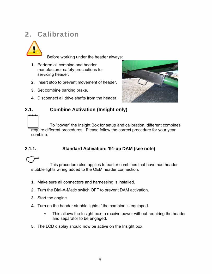
Before working under the header always:
1. Perform all combine and header manufacturer safety precautions for servicing header.
2. Insert stop to prevent movement of header.
3. Set combine parking brake.
4. Disconnect all drive shafts from the header.
2.1. Combine Activation (Insight only)
To “power” the Insight Box for setup and calibration, different combines require different procedures. Please follow the correct procedure for your year combine.
2.1.1. Standard Activation: ’91-up DAM (see note)
This procedure also applies to earlier combines that have had header stubble lights wiring added to the OEM header connection.
1. Make sure all connectors and harnessing is installed.
2. Turn the Dial-A-Matic switch OFF to prevent DAM activation.
3. Start the engine.
4. Turn on the header stubble lights if the combine is equipped.
o This allows the Insight box to receive power without requiring the header and separator to be engaged.
5. The LCD display should now be active on the Insight box.
5
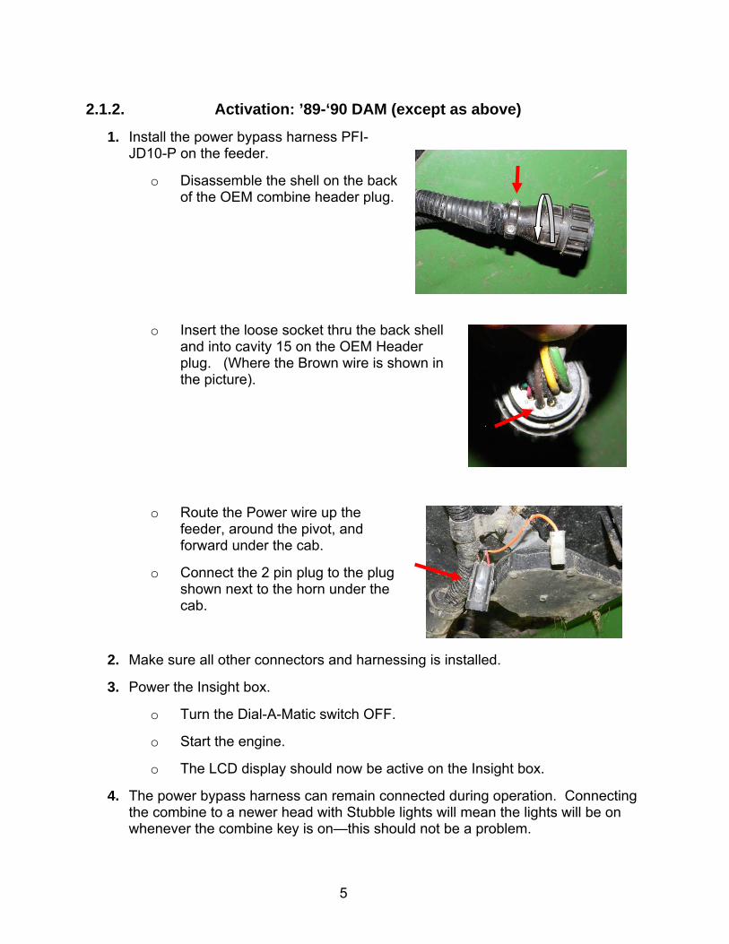
2.1.2. Activation: ’89-‘90 DAM (except as above)
1. Install the power bypass harness PFI-JD10-P on the feeder.
o Disassemble the shell on the back of the OEM combine header plug.
o Insert the loose socket thru the back shell and into cavity 15 on the OEM Header plug. (Where the Brown wire is shown in the picture).
o Route the Power wire up the feeder, around the pivot, and forward under the cab.
o Connect the 2 pin plug to the plug shown next to the horn under the cab.
2. Make sure all other connectors and harnessing is installed.
3. Power the Insight box.
o Turn the Dial-A-Matic switch OFF.
o Start the engine.
o The LCD display should now be active on the Insight box.
4. The power bypass harness can remain connected during operation. Connecting the combine to a newer head with Stubble lights will mean the lights will be on whenever the combine key is on—this should not be a problem.
6
2.2. Initialize Insight
These steps must be performed the first time the Insight box is powered up and each time it is reset. They do not need to be redone each time the Insight box is calibrated.
Read the Insight Overview section of the appendix for basic information about how to use the Insight box.
1. Choose Language
2. On the Insight box.
o Choose “John Deere”
o Choose “9x00/10 & xx20 DAM ”
3. Choose the number of height sensors
For JD flex head conversion, choose 3 For other heads, enter the number of ground sensors.
4. Choose Header Type (if needed)
Chose the appropriate Header type ONLY chose Flex if the head is to be operated in flex mode, not locked up
in rigid mode.
2.3. Calibrate Insight
When you initialize Insight, you will be led directly to this calibration routine. If you wish to recalibrate at any other time – choose “>>Perform Calibration” on the Insight main menu.
2.3.1. Sensor Calibration
1. Park the combine on a level and smooth surface – preferably a cement driveway or shop floor.
2. Follow on-screen instructions.
o “Raise Header” - Press Enter
Raise the head high enough that NO sensors touch the ground: Press Enter
7
o “Lower Header” - Press Enter
Lower the head ALL the way down onto the skids. Make sure that both ends of the header are flat on the ground. Use blocks if necessary. Press
Enter
If an error appears on the Insight box – see the Diagnostics section of this manual.
2.4. Combine Contour-Master Calibration
This calibration should be done each time a combine equipped with Contour-Master has been used on another header with a minimum of once per season. This calibration allows the combine to learn how to level the head.
1. Complete the sensor calibration procedure above.
2. Start the engine and attach the header.
3. Engage the header clutch.
4. Turn off the Contour-Master switch on the armrest.
5. Lower header to the ground (on a level surface) for 2 seconds.
6. Press header raise button.
7. Turn on the Contour-Master switch after the sensors have left the ground (while continuing to raise the header).
8. If the header does not run level, retry the calibration.
8
3. Settings
3.1. Combine Settings
Properly setting the combine is essential to having responsive header control. You should become very familiar with the steps in this section.
Set the automatic drop rate as high as you like without causing head “hunting”. If the head “hunts”, decrease the automatic drop rate.
For 20 series combines see owners manual for location of drop rate valve and accumulator – 9000-9010 series are shown.
3.1.1. Automatic drop rate
1. Use the automatic drop rate valve adjustment knob on the main valve block.
o Turn in all the way then out ½ turn for initial guess.
o If the speed is to fast – hunting will occur.
o If the speed is to slow – the system will not be responsive enough.
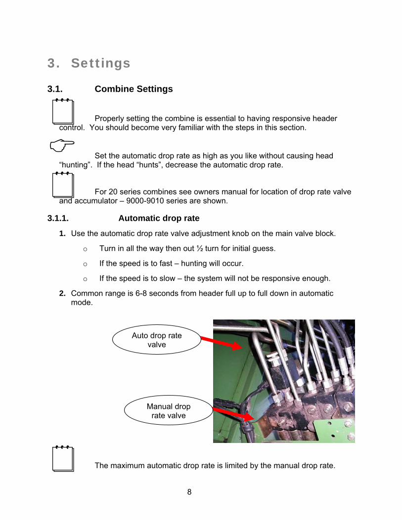
2. Common range is 6-8 seconds from header full up to full down in automatic mode.
The maximum automatic drop rate is limited by the manual drop rate.
Auto drop rate valve
Manual drop rate valve
9
3.1.2. Hydraulic accumulator
1. Close the accumulator valve all the way
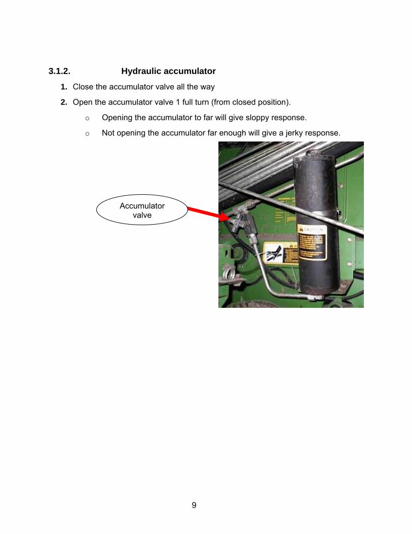
2. Open the accumulator valve 1 full turn (from closed position).
o Opening the accumulator to far will give sloppy response.
o Not opening the accumulator far enough will give a jerky response.
Accumulator valve
10
4. Operation
4.1. Enabling height control
4.1.1. 9x00 and 9x10 series
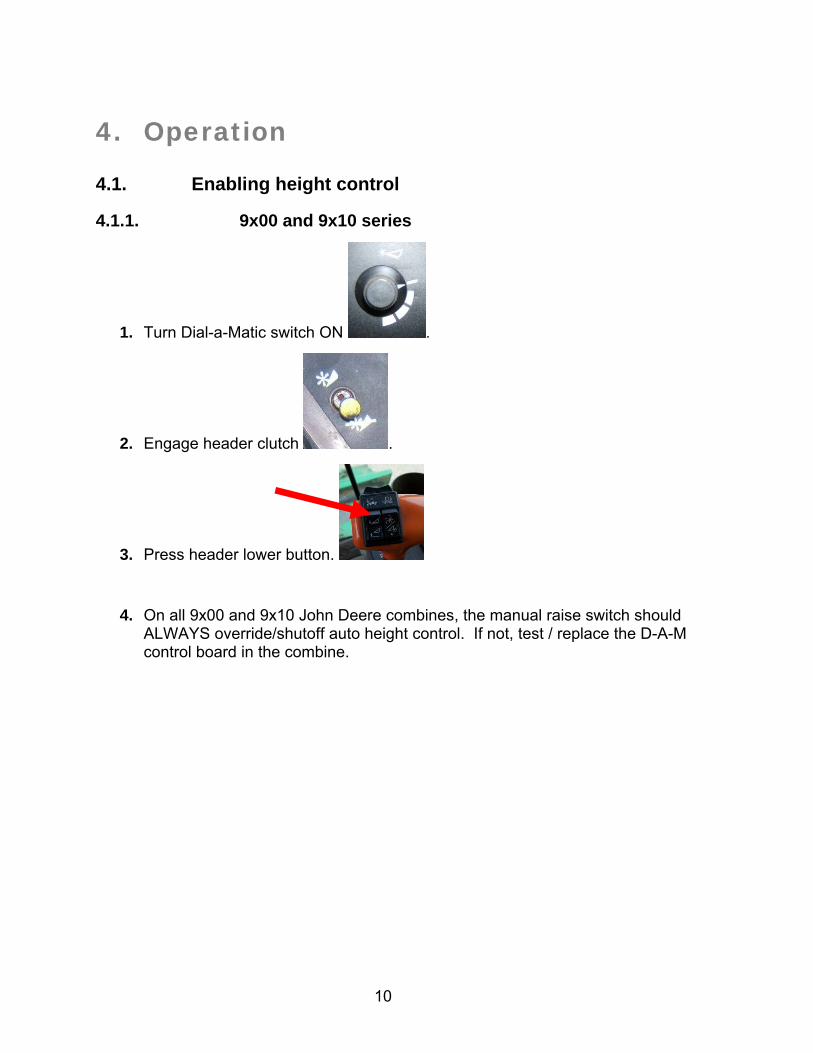
1. Turn Dial-a-Matic switch ON .
2. Engage header clutch .
3. Press header lower button.
4. On all 9x00 and 9x10 John Deere combines, the manual raise switch should ALWAYS override/shutoff auto height control. If not, test / replace the D-A-M control board in the combine.
11
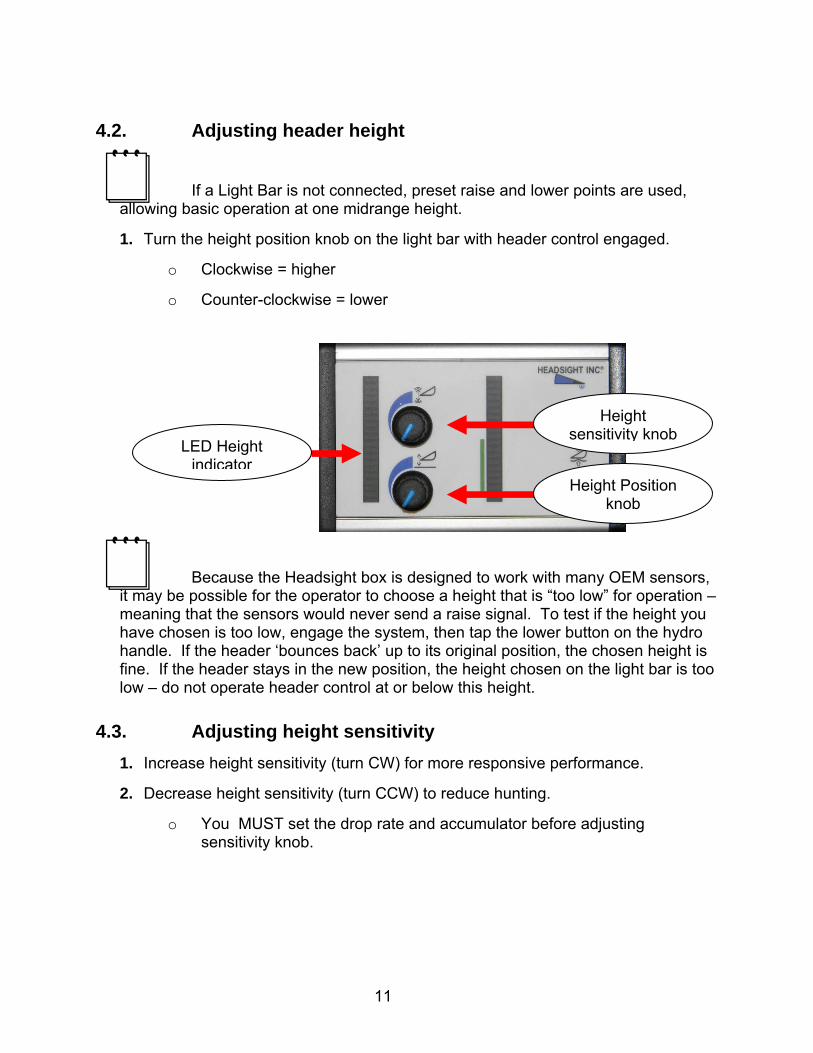
4.2. Adjusting header height
If a Light Bar is not connected, preset raise and lower points are used, allowing basic operation at one midrange height.
1. Turn the height position knob on the light bar with header control engaged.
o Clockwise = higher
o Counter-clockwise = lower
Because the Headsight box is designed to work with many OEM sensors, it may be possible for the operator to choose a height that is “too low” for operation – meaning that the sensors would never send a raise signal. To test if the height you have chosen is too low, engage the system, then tap the lower button on the hydro handle. If the header ‘bounces back’ up to its original position, the chosen height is fine. If the header stays in the new position, the height chosen on the light bar is too low – do not operate header control at or below this height.
4.3. Adjusting height sensitivity
1. Increase height sensitivity (turn CW) for more responsive performance.
2. Decrease height sensitivity (turn CCW) to reduce hunting.
o You MUST set the drop rate and accumulator before adjusting sensitivity knob.
Height sensitivity knob
Height Position knob
LED Height indicator
12
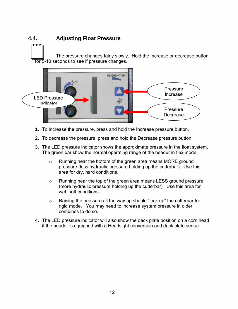
4.4. Adjusting Float Pressure
The pressure changes fairly slowly. Hold the Increase or decrease button for 5-10 seconds to see if pressure changes.
1. To increase the pressure, press and hold the Increase pressure button.
2. To decrease the pressure, press and hold the Decrease pressure button.
3. The LED pressure indicator shows the approximate pressure in the float system. The green bar show the normal operating range of the header in flex mode.
o Running near the bottom of the green area means MORE ground pressure (less hydraulic pressure holding up the cutterbar). Use this area for dry, hard conditions.
o Running near the top of the green area means LESS ground pressure (more hydraulic pressure holding up the cutterbar). Use this area for wet, soft conditions.
o Raising the pressure all the way up should “lock up” the cutterbar for rigid mode. You may need to increase system pressure in older combines to do so.
4. The LED pressure indicator will also show the deck plate position on a corn head if the header is equipped with a Headsight conversion and deck plate sensor.
Pressure Increase
Pressure Decrease
LED Pressure indicator
13
A Insight Overview
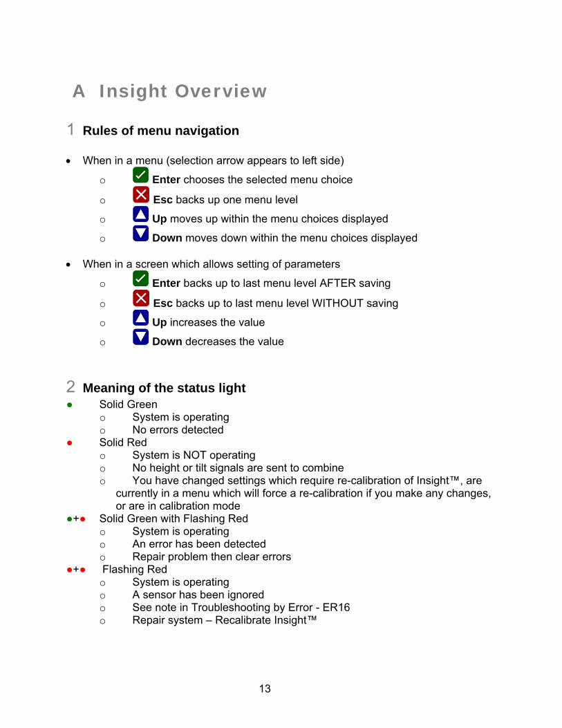
1 Rules of menu navigation When in a menu (selection arrow appears to left side)
o Enter chooses the selected menu choice
o Esc backs up one menu level
o Up moves up within the menu choices displayed
o Down moves down within the menu choices displayed When in a screen which allows setting of parameters
o Enter backs up to last menu level AFTER saving
o Esc backs up to last menu level WITHOUT saving
o Up increases the value
o Down decreases the value
2 Meaning of the status light ● Solid Green
o System is operating o No errors detected
● Solid Red o System is NOT operating o No height or tilt signals are sent to combine o You have changed settings which require re-calibration of Insight™, are
currently in a menu which will force a re-calibration if you make any changes, or are in calibration mode
●+● Solid Green with Flashing Red o System is operating o An error has been detected o Repair problem then clear errors
●+● Flashing Red o System is operating o A sensor has been ignored o See note in Troubleshooting by Error - ER16 o Repair system – Recalibrate Insight™
14
3 Screen contrast adjustment
To increase contrast: + o Press and hold Esc o Press Up to increase contrast (while holding Esc)
To decrease contrast: + o Press and hold Esc o Press Down to decrease contrast (while holding Esc)
4 Resetting Insight™ to defaults
To reset ALL settings + for 5 seconds o Press and hold Esc then o Press and hold Enter while holding Esc o Hold both for 5 seconds
5 Updating Insight Software
Updating software may cause the Foresight option to be disabled. If you have purchased Foresight, contact Headsight before updating software.
5. You will need:
o SD memory card
o Means of loading SD memory card either
A computer with an SD memory card drive
A computer with USB drive and a USB to SD card adapter
A pre-loaded SD card from Headsight
o Small Allen wrench or screwdriver
6. Load SD card with new software files
o Place insighte and insightf in the root directory of the SD card
For example - E:\insighte and NOT E:\my_folder\insighte
DO NOT change the file names
7. If you do not have the new files you may
o Request updated software by email from [email protected]
15
o Download updated software from www.headsight.com (when available)
o Request pre-loaded SD card from Headsight, Inc
8. Disconnect all header connections from the combine
9. Remove 4 screws from the rear of the Insight™ box – remove rear cover
10. Insert programmed SD card into SD card slot on rear of board
11. Power Insight™
o Connect all wiring to combine
o Turn on keyswitch
12. Wait for software to download
o Yellow light on connector will blink while download is in progress
o Green light will turn on solid when download is complete
13. Verify update is successful
o Go to >>About Insight>>Software Version and read software version number
14. Remove power from Insight™
o Turn off key
15. Remove SD card
16. Reinstall rear cover
17. Fasten with screws
16
B Advanced Information
1 Changing Tilt Orifices
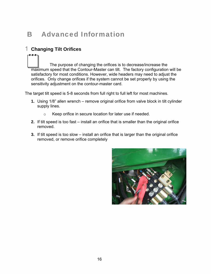
The purpose of changing the orifices is to decrease/increase the maximum speed that the Contour-Master can tilt. The factory configuration will be satisfactory for most conditions. However, wide headers may need to adjust the orifices. Only change orifices if the system cannot be set properly by using the sensitivity adjustment on the contour-master card.
The target tilt speed is 5-8 seconds from full right to full left for most machines.
1. Using 1/8” allen wrench – remove original orifice from valve block in tilt cylinder supply lines.
o Keep orifice in secure location for later use if needed.
2. If tilt speed is too fast – install an orifice that is smaller than the original orifice removed.
3. If tilt speed is too slow – install an orifice that is larger than the original orifice removed, or remove orifice completely
17
2 Connecting the 9 pin T to a 6pin combine Hydro Handle connector
Early model 9000 series level-land combines had a 6 pin connector on the Hydro handle. This must be change to allow connection of the 9 pin T connection.
1. Tools Needed: An Amp Multimate pin removal tool.
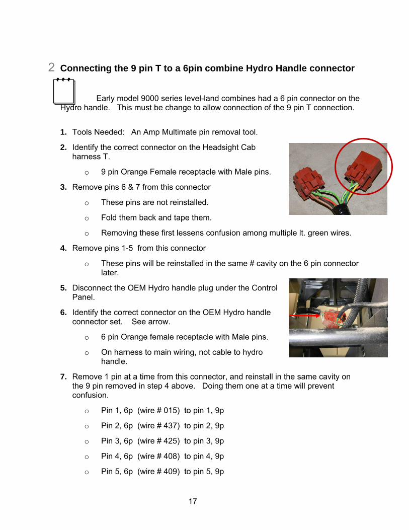
2. Identify the correct connector on the Headsight Cab harness T.
o 9 pin Orange Female receptacle with Male pins.
3. Remove pins 6 & 7 from this connector
o These pins are not reinstalled.
o Fold them back and tape them.
o Removing these first lessens confusion among multiple lt. green wires.
4. Remove pins 1-5 from this connector
o These pins will be reinstalled in the same # cavity on the 6 pin connector later.
5. Disconnect the OEM Hydro handle plug under the Control Panel.
6. Identify the correct connector on the OEM Hydro handle connector set. See arrow.
o 6 pin Orange female receptacle with Male pins.
o On harness to main wiring, not cable to hydro handle.
7. Remove 1 pin at a time from this connector, and reinstall in the same cavity on the 9 pin removed in step 4 above. Doing them one at a time will prevent confusion.
o Pin 1, 6p (wire # 015) to pin 1, 9p
o Pin 2, 6p (wire # 437) to pin 2, 9p
o Pin 3, 6p (wire # 425) to pin 3, 9p
o Pin 4, 6p (wire # 408) to pin 4, 9p
o Pin 5, 6p (wire # 409) to pin 5, 9p
18
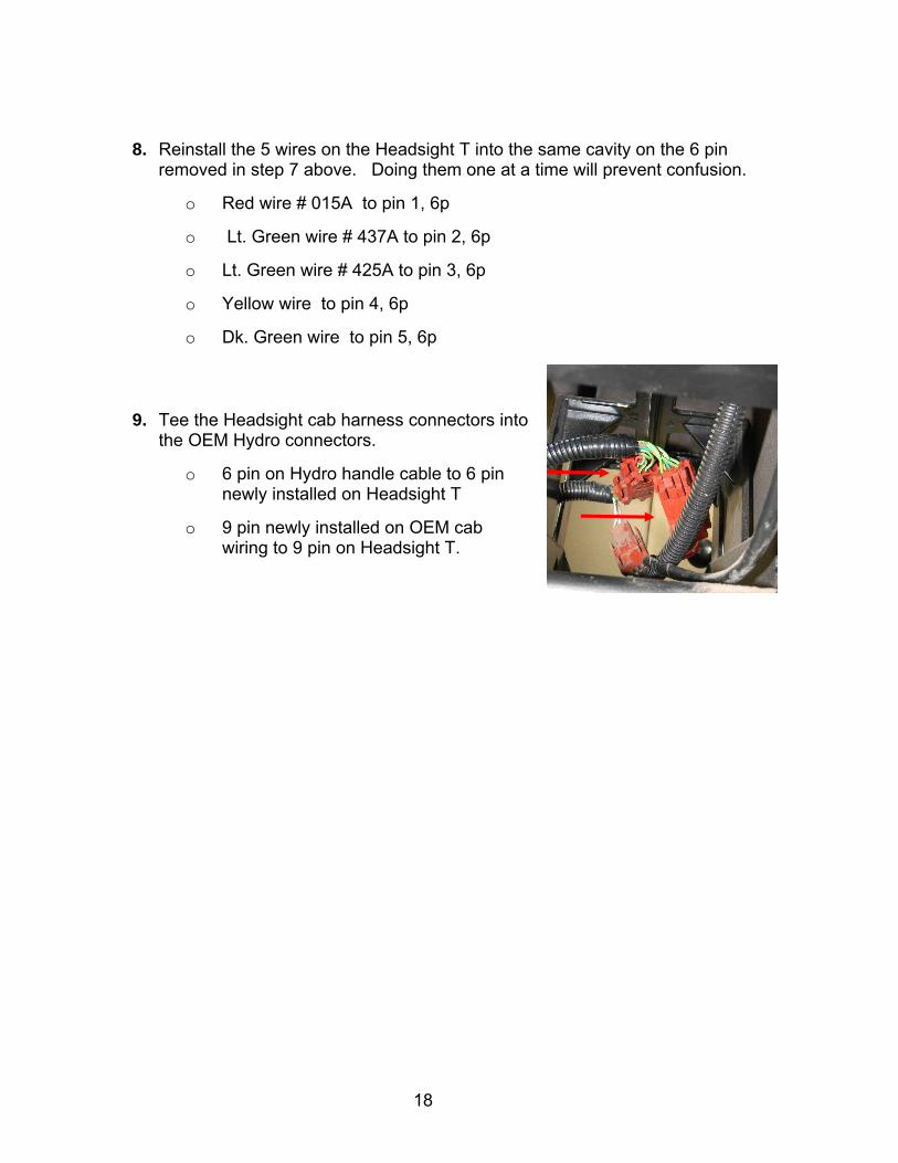
8. Reinstall the 5 wires on the Headsight T into the same cavity on the 6 pin removed in step 7 above. Doing them one at a time will prevent confusion.
o Red wire # 015A to pin 1, 6p
o Lt. Green wire # 437A to pin 2, 6p
o Lt. Green wire # 425A to pin 3, 6p
o Yellow wire to pin 4, 6p
o Dk. Green wire to pin 5, 6p
9. Tee the Headsight cab harness connectors into the OEM Hydro connectors.
o 6 pin on Hydro handle cable to 6 pin newly installed on Headsight T
o 9 pin newly installed on OEM cab wiring to 9 pin on Headsight T.
19
C Diagnostics
1 Theory of Operation All JD Dial-a-Matic (20/00/10 series) combines height control systems work in a
similar way. A review of the following points will help the service technician to understand the complete system which will help when diagnosing specific problems.
1. Each sensor returns a variable voltage to the control box at the rear of the header depending on its height.
o high height = high voltage (approximately 4 volts)
o low height = low voltage (approximately 1 volt)
2. Each sensor has 3 wires
o 5V power
o ground
o signal returned to the control box (varies between approximately 1.0 and 4.0 volts)
3. The Iterface box compares the center input (cutterbar) sensor to the desired height chosen on the light bar in the cab.
o If the height sensor has a lower voltage (is nearer the ground) than the height setpoint voltage – the box sends a raise signal to the combine on pin #5 of the 16 pin header connector.
o If the height sensor has a higher voltage (are farther from the ground) than the height setpoint voltage plus the deadband chosen by the sensitivity knob – the box sends a lower signal to the combine on pin #3 of the 16 pin header connector.
4. The sensitivity knob on the light bar adjusts the size of the deadband.
o The deadband is a small area where the system will neither raise nor lower.
o This helps prevent hunting of the header.
5. The lights on the light bar are visual indicators of head position to the operator.
If a Light Bar is not connected, preset raise and lower points are used, allowing basic operation at one midrange height.
20
6. The left and right sensor signals are scaled to the correct range (0.5-4V) then sent on to the combine on pins 7 and 9 respectively for Contour-Master operation.
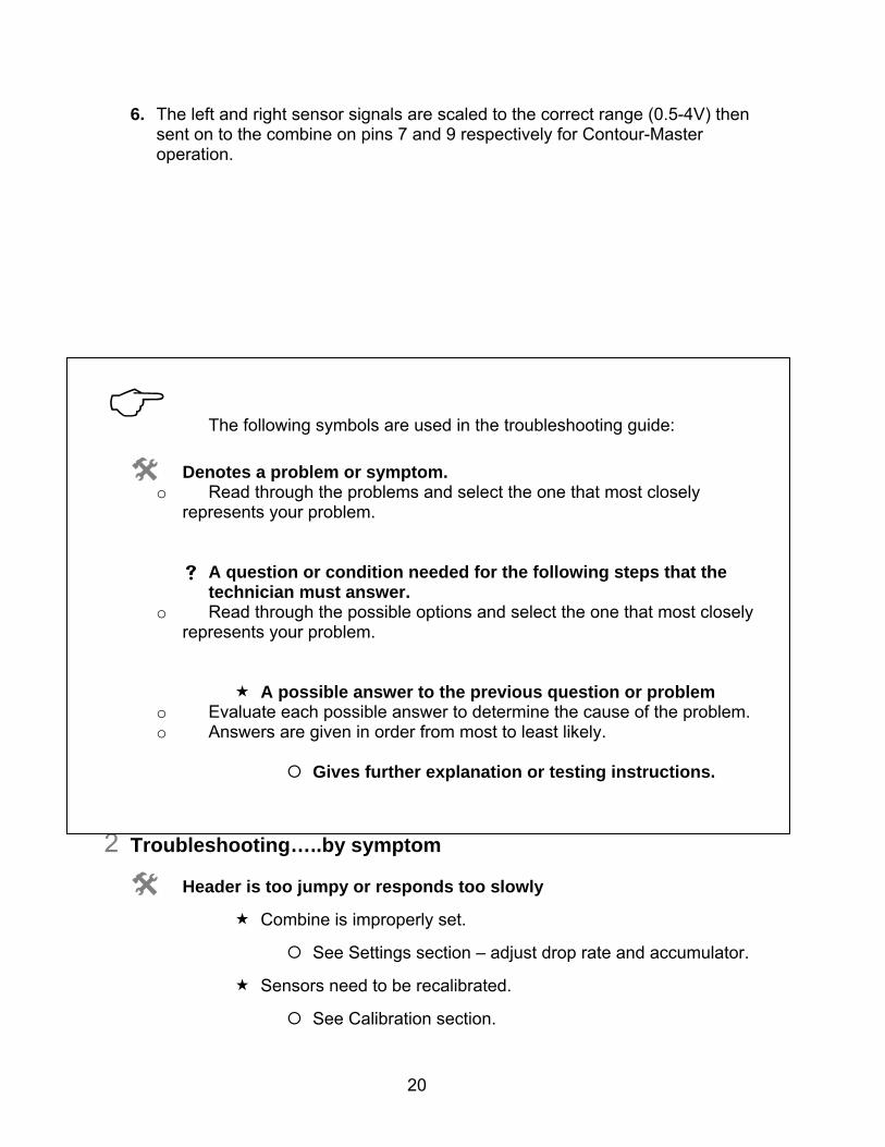
The following symbols are used in the troubleshooting guide:
Denotes a problem or symptom. o Read through the problems and select the one that most closely
represents your problem.
A question or condition needed for the following steps that the technician must answer.
o Read through the possible options and select the one that most closely represents your problem.
A possible answer to the previous question or problem o Evaluate each possible answer to determine the cause of the problem. o Answers are given in order from most to least likely.
Gives further explanation or testing instructions.
2 Troubleshooting…..by symptom
Header is too jumpy or responds too slowly
Combine is improperly set.
See Settings section – adjust drop rate and accumulator.
Sensors need to be recalibrated.
See Calibration section.
21
Header is not level with Contour-Master enabled.
If the header tilts completely to one side:
Verify that the individual sensor wiring is connected to the main wiring harness at the rear of the header properly.
This symptom will occur if the Left and Right sensor wiring are in the incorrect position.
See Installation section for details.
Check individual sensors
If the header is slightly out of level but functions correctly:
Verify that all sensors can move freely through the entire range.
Verify that all sensors are connected, functioning and calibrated as per the Calibration section of this manual.
Recalibrate combine Contour-Master. -See Calibration section.
Height control works but Contour-Master does not
Mate all connectors and engage system.
Keep one person in the seat and all connectors mated (remove back shell and probe through rear of connector).
Under >>Diagnostics>>Detailed Diagnostics>>Left & Right Outputs should be 0.5-4 volts and change as the sensors are moved.
Service combine.
If outputs are not as described above
Recalibrate sensors
Reset or replace Insight.
No automatic operation - height or tilt
Wiring is not connected properly
Header control is not enabled with cab controls.
See Operation section for instructions about how to enable.
If Insight is powered and Green Light is on:
D-A-M “loop” not wired in Headsight™ harness (9000-’10)
22
Unplug 16 pin header plug and measure continuity across Pins 4 & 11 in the Headsight™ half. Pins must be <5 Ohms (short circuit).
Combine D-A-M booster box defective (’20 series only).
Test / repair booster box
Suspect defective Insight™ system.
Test Headsight system by following raise/lower diagnostics below.
If Insight is NOT powered (no lights):
Ensure black ground wire is securely attached to the header frame (combines –‘90).
Combine does not supply 12V on pin 4 of the header connector.
Follow steps in “Troubleshooting…..common combine problems” below
Suspect defective Insight or main harness.
Head drops all the way to ground.
Height position knob on light bar set too low
Rotate knob CW until head raises.
Combine not receiving raise signal.
Under >>Diagnostics>>Detailed Diagnostics>>D-A-M Outputs
o Set the height position knob on the Light bar at MAX. When the head is fully on the ground, Raise should be ON.
o If above is true, but head does not move, check Combine for connection/operation issues.
Contact Headsight
Head raises all the way to top.
Height position knob on light bar set too high.
Rotate knob CCW until head lowers.
Sensor stuck up under head. – remove obstruction.
23
Insight LED flashing Green/Red or Red
Defective sensor or harness (any sensor signal < 1V).
o Troubleshoot sensor
Combine not receiving lower signal.
Under >>Diagnostics>>Detailed Diagnostics>>D-A-M Outputs
o Set the height position knob on the Light bar at MIN. With the head raised up, Lower should be ON.
o If above is true, but head does not move, check Combine for connection/operation issues.
Contact Headsight
Head raises over obstacle but does not lower.
Height position knob on light bar set too high.
Rotate knob CCW until head lowers.
Height sensitivity knob on the light bar set too low.
Rotate knob CW to narrow deadband.
Sensor stuck up under head. – remove obstruction.
Feederhouse position chain mis-adjusted (’00-’20 series).
Combine not receiving lower signal. Under >>Diagnostics>>Detailed Diagnostics>>D-A-M Outputs
o Set the height position knob on the Light bar at MIN. With the head raised up, Lower should be ON.
o If above is true, but head does not move, check Combine for connection/operation issues.
Contact Headsight
Head lowers to selected height but does not raise over obstacles.
Height position knob on light bar set too low
Rotate knob CW until head raises.
Height sensitivity knob on light bar set too low.
24
Rotate CW to narrow dead band.
Defective sensor or harness
Any single sensor defective or disconnected will cause the head to not raise over an obstacle seen only by that sensor. Other sensors should function normally.
Combine not receiving lower signal.
Under >>Diagnostics>>Detailed Diagnostics>>D-A-M Outputs
o Set the height position knob on the Light bar at MAX. When the head is fully on the ground, Raise should be ON.
o If above is true, but head does not move, check Combine for connection/operation issues.
Contact Headsight
3 Troubleshooting…..common combine problems
Unopened or discharged accumulator - Head jumps and jerks whole combine.
Test accumulator as described in combine owner’s manual
Replace or recharge as necessary
No 12 Volts available on the header plug.
Check OEM harness on feeder house for damaged wires.
For JD9x00-9x10 series test with
One person on the seat in the cab
DAM switch in position 1,2,or 3.
Header clutch engaged.
If still no 12V –
o Replace DAM relay in armrest.
o Test/Replace DAM switch.
For xx00-xx20 series test as above and also:
25
Make sure feeder house position chain is properly adjusted to pull rocker free of switch under cab. Check switch for proper operation.
The John Deere D-A-M combines only provide power to the Height Control system when the Feeder House Switch is engaged and the D-A-M rotary Switch is NOT “OFF”. If these switches are on and Pin 4 of the combine header connector is not 11-14 Volts , have the combine serviced.
Manual raise switch does not disengage auto height.
Replace relays on D-A-M controller board in combine.
On all 9000 and 9010 John Deere combines, the manual raise switch should ALWAYS override/shutoff auto height control. If not, test / replace the relays on the D-A-M control board in the combine. This is not a Headsight™ problem.
Manual lower switch does not engage auto height.
Test Headsight™ system as described in “No operation”
Test combine 12 V supply as above.
If all systems appear to be working, with both raise and lower signals sent to the combine.
Check OEM raise/lower wiring
Test D-A-M controller board in combine.
4 Troubleshooting by Insight error codes
ER11 – Sensor 1 (left) signal less than 0.3V Sensor 1 out of adjustment or temporarily disconnected.
Adjust sensor until minimum voltage is greater than 0.3V according to sensor calibration instructions
o Low voltage is with the header on the ground for standard polarity – fully raised polarity is reversed
Calibrate Headsight Box Calibrate Combine
Wiring short Check sensor harness for pinched/broken wiring
Sensor failure
26
See sensor test instructions
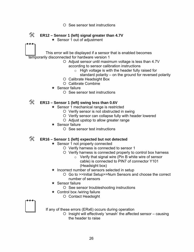
ER12 – Sensor 1 (left) signal greater than 4.7V Sensor 1 out of adjustment
This error will be displayed if a sensor that is enabled becomes temporarily disconnected for hardware version 1
Adjust sensor until maximum voltage is less than 4.7V according to sensor calibration instructions
o High voltage is with the header fully raised for standard polarity – on the ground for reversed polarity
Calibrate Headsight Box Calibrate Combine
Sensor failure See sensor test instructions
ER13 – Sensor 1 (left) swing less than 0.6V Sensor 1 mechanical range is restricted
Verify sensor is not obstructed in swing Verify sensor can collapse fully with header lowered Adjust upstop to allow greater range
Sensor failure See sensor test instructions
ER16 – Sensor 1 (left) expected but not detected Sensor 1 not properly connected
Verify harness is connected to sensor 1 Verify harness is connected properly to control box harness
o Verify that signal wire (Pin B white wire of sensor cable) is connected to PIN7 of connector Y101 (Headsight box)
Incorrect number of sensors selected in setup Go to >>Initial Setup>>Num Sensors and choose the correct
number of sensors Sensor failure
See sensor troubleshooting instructions Control box /wiring failure
Contact Headsight
If any of these errors (ERx6) occurs during operation Insight will effectively ‘smash’ the affected sensor – causing
the header to raise
27
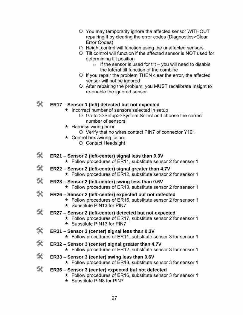
You may temporarily ignore the affected sensor WITHOUT repairing it by clearing the error codes (Diagnostics>Clear Error Codes)
Height control will function using the unaffected sensors Tilt control will function if the affected sensor is NOT used for
determining tilt position o If the sensor is used for tilt – you will need to disable
the lateral tilt function of the combine If you repair the problem THEN clear the error, the affected
sensor will not be ignored After repairing the problem, you MUST recalibrate Insight to
re-enable the ignored sensor
ER17 – Sensor 1 (left) detected but not expected Incorrect number of sensors selected in setup
Go to >>Setup>>System Select and choose the correct number of sensors
Harness wiring error Verify that no wires contact PIN7 of connector Y101
Control box /wiring failure Contact Headsight
ER21 – Sensor 2 (left-center) signal less than 0.3V Follow procedures of ER11, substitute sensor 2 for sensor 1
ER22 – Sensor 2 (left-center) signal greater than 4.7V Follow procedures of ER12, substitute sensor 2 for sensor 1
ER23 – Sensor 2 (left-center) swing less than 0.6V Follow procedures of ER13, substitute sensor 2 for sensor 1
ER26 – Sensor 2 (left-center) expected but not detected Follow procedures of ER16, substitute sensor 2 for sensor 1 Substitute PIN13 for PIN7
ER27 – Sensor 2 (left-center) detected but not expected Follow procedures of ER17, substitute sensor 2 for sensor 1 Substitute PIN13 for PIN7
ER31 – Sensor 3 (center) signal less than 0.3V Follow procedures of ER11, substitute sensor 3 for sensor 1
ER32 – Sensor 3 (center) signal greater than 4.7V Follow procedures of ER12, substitute sensor 3 for sensor 1
ER33 – Sensor 3 (center) swing less than 0.6V Follow procedures of ER13, substitute sensor 3 for sensor 1
ER36 – Sensor 3 (center) expected but not detected Follow procedures of ER16, substitute sensor 3 for sensor 1 Substitute PIN8 for PIN7
28
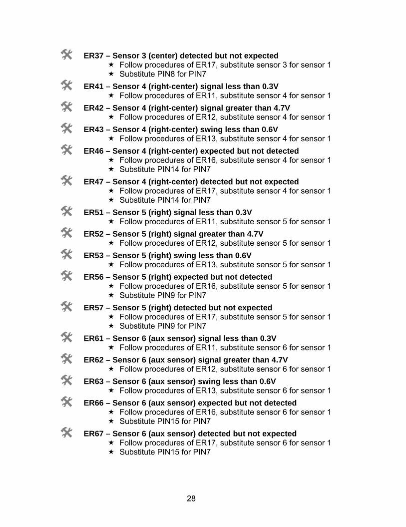
ER37 – Sensor 3 (center) detected but not expected Follow procedures of ER17, substitute sensor 3 for sensor 1 Substitute PIN8 for PIN7
ER41 – Sensor 4 (right-center) signal less than 0.3V Follow procedures of ER11, substitute sensor 4 for sensor 1
ER42 – Sensor 4 (right-center) signal greater than 4.7V Follow procedures of ER12, substitute sensor 4 for sensor 1
ER43 – Sensor 4 (right-center) swing less than 0.6V Follow procedures of ER13, substitute sensor 4 for sensor 1
ER46 – Sensor 4 (right-center) expected but not detected Follow procedures of ER16, substitute sensor 4 for sensor 1 Substitute PIN14 for PIN7
ER47 – Sensor 4 (right-center) detected but not expected Follow procedures of ER17, substitute sensor 4 for sensor 1 Substitute PIN14 for PIN7
ER51 – Sensor 5 (right) signal less than 0.3V Follow procedures of ER11, substitute sensor 5 for sensor 1
ER52 – Sensor 5 (right) signal greater than 4.7V Follow procedures of ER12, substitute sensor 5 for sensor 1
ER53 – Sensor 5 (right) swing less than 0.6V Follow procedures of ER13, substitute sensor 5 for sensor 1
ER56 – Sensor 5 (right) expected but not detected Follow procedures of ER16, substitute sensor 5 for sensor 1 Substitute PIN9 for PIN7
ER57 – Sensor 5 (right) detected but not expected Follow procedures of ER17, substitute sensor 5 for sensor 1 Substitute PIN9 for PIN7
ER61 – Sensor 6 (aux sensor) signal less than 0.3V Follow procedures of ER11, substitute sensor 6 for sensor 1
ER62 – Sensor 6 (aux sensor) signal greater than 4.7V Follow procedures of ER12, substitute sensor 6 for sensor 1
ER63 – Sensor 6 (aux sensor) swing less than 0.6V Follow procedures of ER13, substitute sensor 6 for sensor 1
ER66 – Sensor 6 (aux sensor) expected but not detected Follow procedures of ER16, substitute sensor 6 for sensor 1 Substitute PIN15 for PIN7
ER67 – Sensor 6 (aux sensor) detected but not expected Follow procedures of ER17, substitute sensor 6 for sensor 1 Substitute PIN15 for PIN7
29
5 Reading voltages on the Insight box
7. From the main menu, go to >> Diagnostics>>Disp Sensor Voltages
o This shows real-time the voltage coming from each sensor.
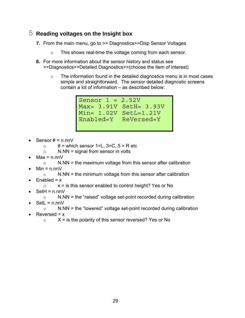
8. For more information about the sensor history and status see >>Diagnostics>>Detailed Diagnostics>>(choose the item of interest)
o The information found in the detailed diagnostics menu is in most cases simple and straightforward. The sensor detailed diagnostic screens contain a lot of information – as described below:
Sensor # = n.nnV
o # = which sensor 1=L, 3=C, 5 = R etc o N.NN = signal from sensor in volts
Max = n.nnV o N.NN = the maximum voltage from this sensor after calibration
Min = n.nnV o N.NN = the minimum voltage from this sensor after calibration
Enabled = x o x = is this sensor enabled to control height? Yes or No
SetH = n.nnV o N.NN = the “raised” voltage set-point recorded during calibration
SetL = n.nnV o N.NN = the “lowered” voltage set-point recorded during calibration
Reversed = x o X = is the polarity of this sensor reversed? Yes or No
Sensor 1 = 2.52V Max= 3.91V SetH= 3.93V Min= 1.02V SetL=1.21V Enabled=Y ReVersed=Y
30
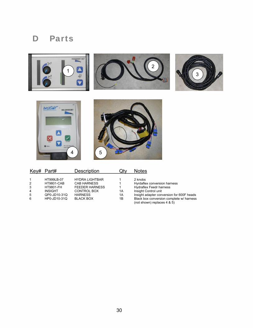
D Parts
Key# Part# Description Qty Notes 1 HT999LB-07 HYDRA LIGHTBAR 1 2 knobs 2 HT9801-CAB CAB HARNESS 1 Hyrdaflex conversion harness 3 HT9801-FH FEEDER HARNESS 1 Hydraflex Feedr harness 4 INSIGHT CONTROL BOX 1A Insight Control unit 5 QP0-JD10-31Q HARNESS 1A Insight adapter conversion for 600F heads 6 HP0-JD10-31Q BLACK BOX 1B Black box conversion complete w/ harness
(not shown) replaces 4 & 5)
5
21
3
4

31

32