james ricles nheri lehigh ef muhannad suleiman … · neesr-sg self centering damage-free seismic...
TRANSCRIPT
James Ricles
NHERI Lehigh EF
Muhannad Suleiman
ATLSS Faculty

NHERI Lehigh EF Testing Capabilities for
Natural Hazards Engineering Research
• Large-Scale Hybrid Simulation
• Large-Scale Real-time Hybrid Simulation
• Large-Scale Real-time Hybrid Simulation with Multiple Experimental Substructures
• Geographically Distributed Hybrid Simulation
• Geographically Distributed Real-time Hybrid Simulation
• Predefined load or displacements (Quasi-static testing or characterization testing)
• Dynamic testingMulti-directional Dynamic Testing
of Pipe Couplers

Example Project & Testing Types
Test Specimen Mode of Testing
R/C bridge-soil-foundation Distributed hybrid simulations
Building with piping system Multi-directional real-time hybrid simulations
Self-centering beam-to-column moment connections Characterization tests
Self-centering frame systems Characterization, hybrid simulations
R/C bridge with MR dampers Real-time hybrid simulations
Passive and semi-active dampers Characterization, hybrid and real-time hybrid
simulations
Steel frame building with MR dampers Real-time hybrid simulations with single and
multiple experimental substructures, real-time
distributed hybrid simulations
Tsunami-driven debris Dynamic impact loading
Post-tensioned coupled shear wall systems Characterization testing, multi-mode dynamic
testing
Laterally and axially loaded SSI pile tests Characterization testing, quasi-static testing

Pre-NEESR MISST: Multi-Site Soil-Structure-Foundation Interaction EQ Simulation
Test – UIUC, RPI, Lehigh
UI-SIMCOR
Distributed Hybrid Simulation Test SetupLehigh University
Pier test subassembly
UIUC
Pier test subassembly
RPI
Soil test subassembly
NCSA
Remaining soil, superstructure
analytical subassembly
Schematic Courtesy
of UIUC
I-10 Collector-Distributor 36
Damaged during 1994
Northridge EQ

• Evaluate seismic performance of Victaulic grooved
couplers for building piping systems
• Evaluate seismic performance of alternative pipe bracing
details
Objectives
Rigid bracingFlexible bracing
Grooved coupler
Multi-directional Large-Scale Real-time Hybrid Simulation of 3-story
Building with Piping System – Lehigh

Analytical
Substructure
Experimental
Substructure
D5
D6
d2
d1
d4
d3
d6
d5
3-story MRF
Piping system
D = T d
d2
d1
d4
d3
d6
d5
Multi-directional Large-Scale Real-time Hybrid Simulation of 3-story
Building with Piping System – Lehigh

Multi-directional Large-Scale Real-time Hybrid Simulation of 3-story
Building with Piping System – LehighRTHS: 1994 Northridge EQ, Canogo Park (MCE)
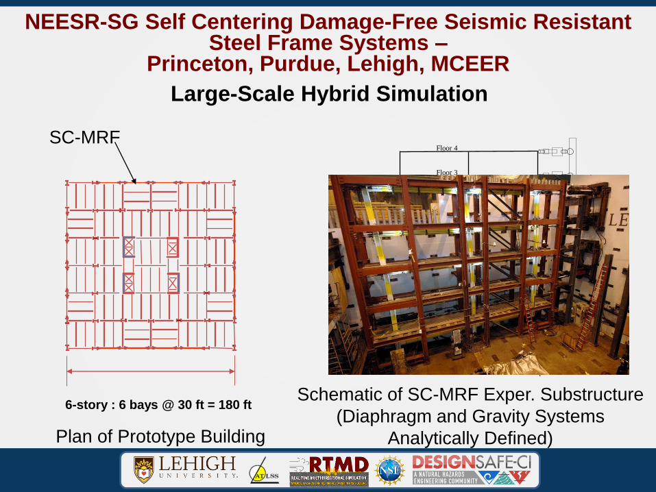
NEESR-SG Self Centering Damage-Free Seismic Resistant Steel Frame Systems –
Princeton, Purdue, Lehigh, MCEER
6-story : 6 bays @ 30 ft = 180 ft
Plan of Prototype Building
- .
actuator
self centering column base
PT
an
chor
column
ED element
PT steel
PT
forc
e se
nso
r
beam
gap opening sensor
Floor 1
Floor 2
Floor 3
Floor 4
keeper
detail
½ story to representbasement
Schematic of SC-MRF Exper. Substructure
(Diaphragm and Gravity Systems
Analytically Defined)
SC-MRF
Large-Scale Hybrid Simulation

NEESR-SG Self Centering Damage-Free Seismic Resistant Steel Frame Systems –
MCE (2500 yr Return Period EQ) Hybrid Simulation Results
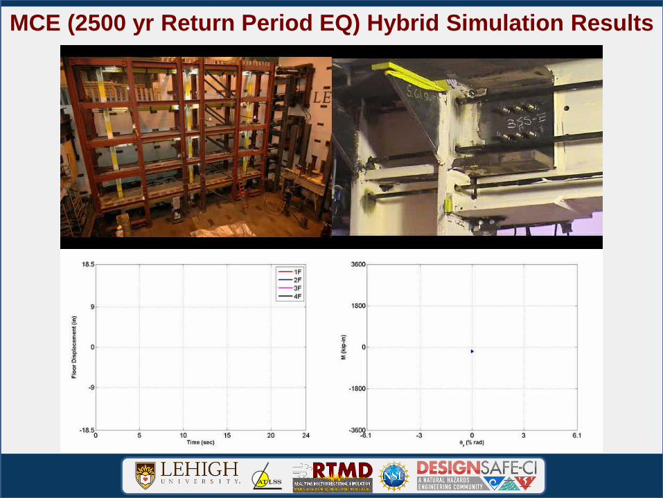
Videos
MCE (2500 yr Return Period EQ) Hybrid Simulation Results

NEESR-SG Self Centering Damage-Free Seismic Resistant Steel Frame Systems - Princeton, Purdue, Lehigh, MCEER
6-story : 6 bays @ 30 ft = 180 ft
Plan of Prototype Building
SC-CBF Exper. Substructure
(Diaphragm and Gravity Systems
Analytically Defined)
SC-CBF
Large-Scale Hybrid Simulations
NorthSouth
Vertical post-
tensioning
Vertical gap
opening joints

1995 Takitori, Japan EQ (mMCE + 3s) Simulation Results

Development Of Advanced Servo-Hydraulic Control and Test Bed For Real-Time Testing Of Damped Structures
Subjected To Earthquakes - Lehigh
Real-time Hybrid SimulationDamper Hysteretic Response
-100
-75
-50
-25
0
25
50
75
100
-15 -10 -5 0 5 10 15
Damper Deformation - mm
Da
mp
er
Fo
rce
- k
N
First Floor Lateral Displacement
-20
-10
0
10
20
0 5 10 15 20 25 30
Time - sec
Dis
pla
cem
ent
- m
mUndamped Frame
Damped Frame
N
RTMD
Actuator
Dampers
North
A-FrameSouth
A-Frame
Roller
Bearings
Actuator
Support
Loading
Stub
NN
RTMD
Actuator
Dampers
North
A-FrameSouth
A-Frame
Roller
Bearings
Actuator
Support
Loading
Stub
N
RTMD
Actuator
Dampers
North
A-FrameSouth
A-Frame
Roller
Bearings
Actuator
Support
Loading
Stub
NN
RTMD
Actuator
Dampers
North
A-FrameSouth
A-Frame
Roller
Bearings
Actuator
Support
Loading
Stub
Floor 2
damper
N
RTMD
Actuator
Dampers
North
A-FrameSouth
A-Frame
Roller
Bearings
Actuator
Support
Loading
Stub
NN
RTMD
Actuator
Dampers
North
A-FrameSouth
A-Frame
Roller
Bearings
Actuator
Support
Loading
Stub
Floor 1
damper
Floor 3
damper
1st Flr Damper 2nd Flr Damper
3rd Flr Damper
Close up view of
damperExperimental Substructures
(MRFs, Diaphragm and Gravity
Systems Analytically Defined)
6-story : 6 bays @ 30 ft = 180 ft
Plan of Prototype Building
Elevation of MRF with Passive Dampers
MRF with Passive Dampers
dampers
dampers
dampers
dampers
dampers1st Flr Damper

Full-Scale Nonlinear Viscous Dampers
Damper testbed
-60 -40 -20 0 20 40 60-600
-400
-200
0
200
400
600
Damper deformation (mm)
Dam
per
forc
e (
kN
)
f=0.5 Hzf=1.0 Hz
f=1.5 Hz
f=2.0 Hz
(b)
Characterization testing
-800 -400 0 400 800-600
-400
-200
0
200
400
600
Damper velocity (mm/s)
Dam
per
forc
e (
kN
)
f=4.0 HZ
f=3.0 HZ
f=2.0 HZ
f=1.5 HZ
f=1.0 HZ
f=0.5 HZ
f=0.25 HZ
Damper force - deformation Damper force - velocity
0 2 4 6 8 10 12-1.5
-1
-0.5
0
0.5
1
1.5
Time (s)
Actu
ato
r str
oke
(in
ch
es)
3 ramp downcycles
2 ramp upcycles
7 stable full cycles
Loading Protocol
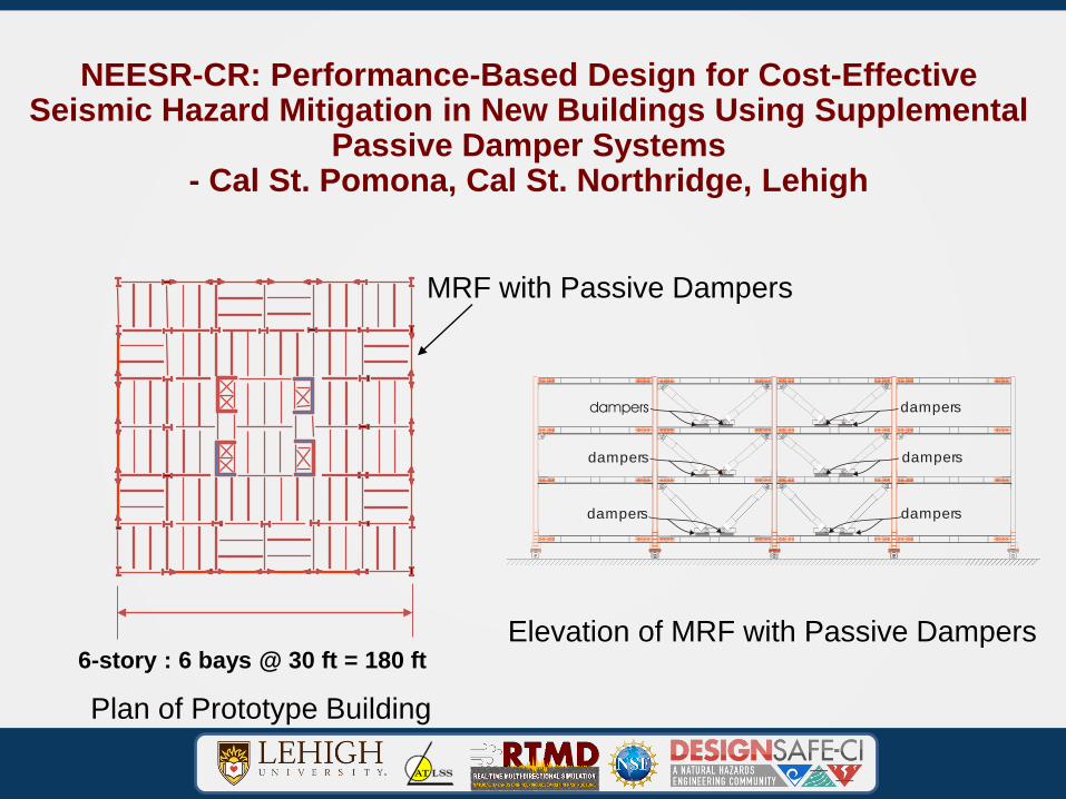
NEESR-CR: Performance-Based Design for Cost-Effective Seismic Hazard Mitigation in New Buildings Using Supplemental
Passive Damper Systems- Cal St. Pomona, Cal St. Northridge, Lehigh
6-story : 6 bays @ 30 ft = 180 ft
Plan of Prototype Building
Elevation of MRF with Passive Dampers
MRF with Passive Dampers
dampers
dampers
dampers
dampers
dampers

NEESR-CR: Performance-Based Design for Cost-Effective Seismic
Hazard Mitigation in New Buildings Using Supplemental Passive
Damper Systems
Real-time Hybrid Simulation – MRF, Gravity Frames Anl Sub

RTHS Phase-2: MCE level 1994 Northridge Earthquake RRS318 component
Real-time Hybrid Simulation: MRF + Braced Frame Exp Sub.

NEESR-SG Performance-Based Design and Real-time Large-scale Testing to Enable Implementation of Advanced Damping Systems –
Purdue, UIUC, CUNY, UConn, Lehigh
6-story : 6 bays @ 30 ft = 180 ft
Plan of Prototype Building
Elevation of MRF with MR Dampers
MRF with MR dampers
Real-time Hybrid Simulation
dampers
dampers
dampers
dampers
dampers

NEESR-SG PBD and Real-time Large-scale Testing to Enable
Implementation of Advanced Damping Systems – Purdue, UIUC, CUNY,
UConn, Lehigh RTHS: 1994 Northridge EQ (0.80*DBE), Semi-active MR
Dampers
Analytical
Substructure
Experimental Substructure – CBF with MR Dampers

NEESR-CR Impact Forces from Tsunami-driven Debris
Dynamic Impact Loading – Univ Hawaii, Oregon St., Lehigh
Dynamic Impact Loading
Test Setup Cargo Shipping
Container Debris
High Speed Video of Impact of Cargo
Shipping Container with Structure
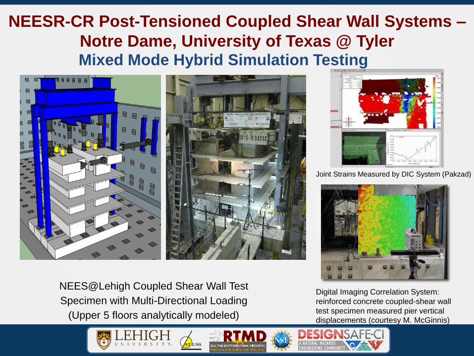
NEESR-CR Post-Tensioned Coupled Shear Wall Systems –
Notre Dame, University of Texas @ Tyler
Digital Imaging Correlation System:
reinforced concrete coupled-shear wall
test specimen measured pier vertical displacements (courtesy M. McGinnis)
Joint Strains Measured by DIC System (Pakzad)
NEES@Lehigh Coupled Shear Wall Test
Specimen with Multi-Directional Loading
(Upper 5 floors analytically modeled)
Mixed Mode Hybrid Simulation Testing
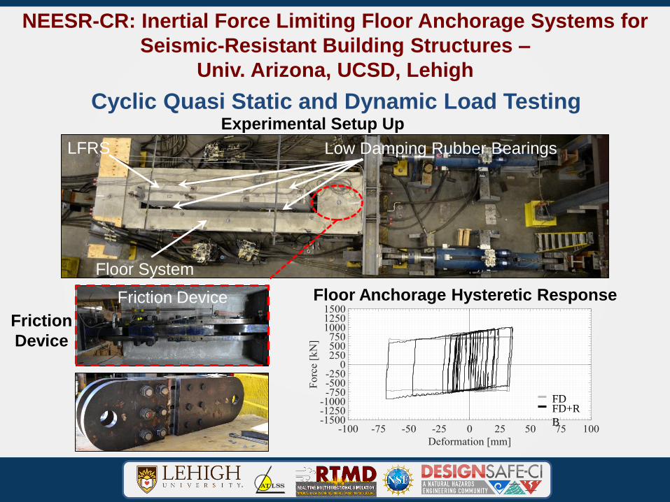
NEESR-CR: Inertial Force Limiting Floor Anchorage Systems for
Seismic-Resistant Building Structures –
Univ. Arizona, UCSD, Lehigh
Cyclic Quasi Static and Dynamic Load Testing
FDFD+R
B
Experimental Setup Up
Friction Device
Low Damping Rubber BearingsLFRS
Floor System
Friction
Device
Floor Anchorage Hysteretic Response

Pile
Actuator
Displacement
transducers
NSF-CMMI: Enhancement of Vertical Element for Foundation
Supported by Ureolytic Carbonate Precipitation
Lehigh, Arizona StateVertical Tests on Biomodified Soil-Pervious Pile Systems

Below the pile
tip 76 mm
140 mm
229 mm
Pile diameter: 76 mm
Soil surface
NSF-CMMI: Enhancement of Vertical Element for Foundation
Supported by Ureolytic Carbonate Precipitation
Lehigh, Arizona StateVertical Tests on Biomodified Soil-Pervious Pile Systems

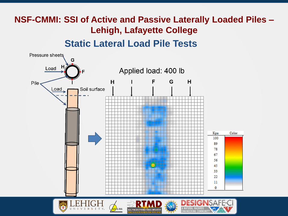
NSF-CMMI: SSI of Active and Passive Laterally Loaded Piles –
Lehigh, Lafayette College
Static Lateral Load Pile Tests

NSF-CMMI: SSI of Active and Passive Laterally Loaded Piles –
Lehigh, Lafayette College
Static Lateral Load Pile Tests
Pile
Pressure
sheet
Load
Note:
:SAA
:In-soil null pressure sensors
at depth of 352 mm below
soil surface
1
2 3
4
5
6
7
In-soil
null
pressure
sensor
NO.
Radial
distance
to pile
center
(mm)
1 152
2 152
3 737
4 152
5 356
6 356
7 76
762 mm
102 mm
76 mm
1.8 m
1.8 m
102mm
25 mm
Load
Pile top
displacement
transducer
78 2 35
Soil surface
1394 mm
106 mm
102 mm
98 mm
SAA
Pressure
sheet
35
2 m
m4
57
mm
38
1 m
m
Pressure
sheet
Back side
of pile
Front side
of pile
NSF-CMMI: SSI of Active and Passive Laterally Loaded Piles –
Lehigh, Lafayette College
Static Lateral Load Pile Tests

NSF-CMMI: SSI of Active and Passive Laterally Loaded Piles –
Lehigh, Lafayette College
Static Lateral Load Pile Tests

NSF-CMMI: SSI of Active and Passive Laterally Loaded Piles –
Lehigh, Lafayette College
Static Lateral Load Pile Tests

NSF-CMMI: SSI of Active and Passive Laterally Loaded Piles –
Lehigh, Lafayette College
Static Lateral Load Pile Tests
Thank You