james city county guidelines for installing solar energy
TRANSCRIPT

1 | P a g e
James City County Guidelines for Installing Solar Energy Systems
This handout is to provide plan review and inspection guidelines for solar energy systems
CONTENTS
Solar Photovoltaic (PV) System Permitting
Structural Plan Review Guidelines
Electrical and Plumbing Plan Review Guidelines
Structural and Electrical Inspection Guidelines
JCC Typical Details
Self-Certification Form for Rooftop Inspection

2 | P a g e
Solar Photovoltaic (PV) System Permitting
Getting Started In most cases, solar panels, whether ground or roof mounted, that service an existing building or structure are generally permitted as an accessory use. However, to be considered an accessory use the amount of solar energy produced by such panels should be limited to the amount of energy needed to service an existing building or structure. Proposals that exceed the amount to service an existing building or structure must be reviewed by the Zoning Division to determine if other approvals are required. Installation of roof or ground mounted solar panels for non-residential buildings must receive site plan approval and comply with all requirements set forth in that zoning district such as building setbacks and height limitation. It is highly recommended to submit a conceptual plan to the Planning Division prior to developing an engineered site plan. This will allow staff to review the site and identify any possible conditions that may conflict with the proposal. Installation of roof or ground mounted solar panels for residential buildings will be reviewed during the building permit process. The proposed panels must comply with all applicable building setbacks and height limitation requirements for the zoning district in which the structure is located. Please be aware that many subdivisions have additional design guidelines that may regulate the proposal panels. It is recommended that homeowners contact Zoning staff to review and identify any possible conditions that may conflict with the proposal.
PermitLink
James City County has transitioned to a fully automated permitting system called PermitLink. You can use PermitLink to apply for a permit, check the status of your permit and/or plan review, schedule inspections, and receive inspection results. Please visit the PermitLink Portal for tutorials and the latest system updates.
For a Solar PV Project you will:
Create a PermitLink account if you do not already have one.
Select the applicable Building and Electrical Permit applications.
Upload Construction Documents.
Typical Drawings
Typical Drawings are included that can be submitted for small residential solar energy installations, 15 k.w. or less and solar hot water systems to help ensure a safe installation at a minimal cost to the customer. To use the County Typical Drawings for residential systems, the installation must comply with the attached Structural and Electrical Plan Review document Part A.
For larger residential systems, commercial systems, and systems that do not meet the requirements for using the County Typical Drawing, a plan designed by a Registered Design Professional (RDP) will need to be submitted for plan review. However, prior to plan review of these types of systems by Building Safety and Permits, applicants should first consult with the James City County Planning and Zoning Divisions to determine whether a Special Use Permit, Site Plan, or other approval process is required.

3 | P a g e
Checklist
The basic, pre-submittal checklist below contains the minimum information and project plan details required when applying to install a residential or small commercial solar PV system. The checklist is designed to provide transparent and well-defined information to minimize the number of required revisions and expedite the application and review process.
Please review the James City County Guidelines for Installing Solar Energy Systems for Details on:
Structural Plan Review (page 4-5)
Electrical and Plumbing Plan Review (page 6-7)
Structural and Electrical Inspections (page 9-10)
JCC Typical Drawing Details (page 10-14)
Self-Certification Form for Rooftop Inspection (page 17)
Additional Required Documents (page 6):
The proposed site diagram showing the layout of the installation.
The County Typical Electrical Plan where applicable or an Electrical Plan designed by a RDP or Master Electrician.
The major components Specification sheets and the manufacturer's installation instructions. Any Zoning/Planning approvals as required for ground mounted and Commercial Solar Energy
Systems, such as commercial site plans.
Permit Fees Required permit fees for an application for a solar system include both building permit fees and electrical permit fees.
● Building Permit Fee: Total Project Cost X $.0105, plus 2% State Levy
● Electrical Permit: $52.50, plus 2% State Levy = $53.55
● Plan Review Fee: $15.75 Example = A $20,000.00 project will be subject to $283.50 in permit fees.
(20,000 X $.0105) X 2% = 214.2 + 53.55 + 15.75 = $283.50
Complete fee information can be found in Appendix A – Fee Schedule for Development Related Permits in the James City County Code of Ordinances.
Review Process Timeline The Building Safety and Permit Division is committed to providing timely review of solar PV permit applications. Best efforts are made to review one- and two-family dwelling applications within fifteen (15) days and commercial/non-residential permit applications in twenty (20) days. While these turnaround times are typical, they not guaranteed as other reviews and approvals may affect some projects. For commercial/non-residential permit applications, the review timeline and fees for any necessary approvals (Special Use Permit, Site Plan, etc.) will be determined through coordination with the Zoning and Planning Divisions.

4 | P a g e
Permit Expiration Failure to start the work authorized by a permit within six (6) months of the date of issue renders the permit inactive. A permit extension fee must be paid to reactivate the permit. All work must be complete within eighteen (18) months of the issue date.
Scheduling an Inspection Please visit PermitLink to schedule inspections. Typically, inspections are completed within one (1) day after a request has been made.
Inspection Requirements:
Residential solar installations require one (1) inspection (Combined Building and Electric.), whereas larger commercial installations greater than 15 k.w. require separate inspections for Building and Electric.
Refer to James City County Guidelines for Installing Solar Energy System (page 7-9).
Contact Information Building Safety and Permits Email: [email protected] Phone: 757-253-6620 Fax: 757-259-4038 Hours of Operation: Monday-Friday, 8 a.m.-5 p.m. Physical Address Mailing Address 101 Mounts Bay Road PO Box 8784 Building E Williamsburg, VA 23187 Williamsburg, VA 23185 Planning and Zoning Divisions Email: [email protected] Phone: 757-253-6685 Hours of Operation: Monday-Friday, 8 a.m.-5 p.m. Physical Address Mailing Address 101 Mounts Bay Road PO Box 8784 Building A Williamsburg, VA 23187 Williamsburg, VA 23185

5 | P a g e
Plan Review Requirements for Installation of Solar Energy Systems
(Photovoltaic Panels and Solar Hot Water Systems)
Roof and Ground Mounted
Structural Requirements A. Residential Roof Installation:
1. Requirements for Using County Details:
Structural design and plans for the installation of modules shall be prepared by an RDP or the
installing contractor and submitted for review. In lieu of the design prepared by an RDP or the
contractor, the County details1
for the installation of solar energy systems can be used, provided
the following conditions are met: A. The mounting structure is an engineered product designed and listed to mount modules. B. The roof truss system is an engineered product. C. Roof trusses/rafters shall not be over-spanned. Use IRC span tables to determine if your
truss/rafter system is over-spanned. D. Building Structure is fully enclosed. E. Roof is flat, hip with pitch less than 27 degrees, or gable with pitch less than 45 degrees. F. The roof type is lightweight (dead load not greater than 20 PSF). G. The roof has single roof covering. H. The spacing between attachment points of the rails shall not exceed four feet. I. Provide the roof plan showing the layout of the modules. J. Provide manufacturer’s installation recommendations and product specifications. K. The longer dimension of module shall not be more than 65 inches; the area shall be limited
to 15 square feet and the longer dimension shall be perpendicular to the supporting beam/rail.
L. Module shall flush with roof/wall (Modules are parallel to the roof/wall surface with no more than 3 inches difference between ends of assembly; and with no more than 10 inches space between roof surface and the bottom of the modules.
M. Dead weight per attachment point will not exceed 45 lbs. N. The distributed weight of the modules will not exceed 5 psf.
The flow chart below is a guide to determine if you will comply with items M and N of the above conditions:
Mounting System Manufacturer Product Name and Model Number
Total Dead Weight of Modules and Rails lbs
Total Number of Attachment Points
Weight per Attachment Point (b÷c) lbs
Total Surface Area of Modules square foot
Distributed Weight of Module on Roof (b÷f) lbs per square foot if any of the above conditions listed in A through N are not met these details cannot be used.
1 The County Details shall be used in conjunction with manufacturer’s installation instructions.

Plan Review Requirements for Installation of Solar Energy Systems
(Photovoltaic Panels and Solar Hot Water Systems) Roof and Ground Mounted (Continued)
6 | P a g e
2. Solar Modules Requiring Designs by RDP / Contractor
If the roof system has:
1. Rafter or trusses that are over-spanned or site built.
2. The dead weight of the array is over 5 psf on any roof construction.
3. The attachment points have dead loads exceeding 45 lbs.
4. Module does not meet any of the conditions in Section A.1, A through N.
The following shall be provided:
1. Engineering calculations and details showing that the roof structure will support the modules.
2. A framing plan that shows details for how you will strengthen the truss/rafter.
Worksheet for evaluation of roof mounted modules:
This section is for evaluating roof structural members that are site built or are not engineered
trusses or rafters.
1. Roof construction: □Rafters □Trusses □Other:
2. Describe site-built rafter or site-built truss system:
A. Rafter Size: x inches
B. Rafter Spacing: inches
C. Maximum unsupported span: feet, inches
D. Are the rafters over-spanned? Use the span tables from the applicable International Residential Code (IRC) to determine if the rafters are over-spanned.
B. Commercial Installations:
All commercial module installations shall require design calculations and details of the structural supporting members by an RDP. Details shall include layout and attachment details. In addition, a copy of the approved site plan must be submitted.
C. Ground Mounted Module:
1. Mounting structure shall require engineering calculations and details by an RDP or AES contractor.
2. Details shall include module supports, framing members, foundation posts, footings and module attachment method to mounting structure.
3. Provide manufacturer’s installation manual, including product specification.
4. Copy of approved site plan must be submitted.
D. Inspections:
Penetrations through fire rated assemblies as a result of module installation shall be inspected. Refer to the section on inspections for other inspection requirements.
Inspection Requirements for Installation of Solar Energy Systems
(Photovoltaic Panels and Solar Hot Water Systems) Roof and Ground Mounted (Continued)
7 | P a g e
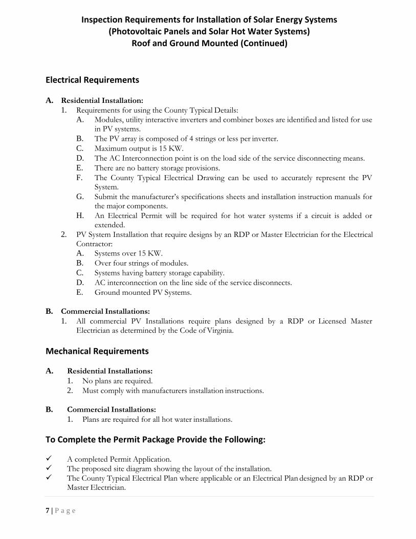
Electrical Requirements A. Residential Installation:
1. Requirements for using the County Typical Details:
A. Modules, utility interactive inverters and combiner boxes are identified and listed for use in PV systems.
B. The PV array is composed of 4 strings or less per inverter.
C. Maximum output is 15 KW.
D. The AC Interconnection point is on the load side of the service disconnecting means.
E. There are no battery storage provisions.
F. The County Typical Electrical Drawing can be used to accurately represent the PV System.
G. Submit the manufacturer’s specifications sheets and installation instruction manuals for the major components.
H. An Electrical Permit will be required for hot water systems if a circuit is added or extended.
2. PV System Installation that require designs by an RDP or Master Electrician for the Electrical Contractor:
A. Systems over 15 KW.
B. Over four strings of modules.
C. Systems having battery storage capability.
D. AC interconnection on the line side of the service disconnects.
E. Ground mounted PV Systems.
B. Commercial Installations:
1. All commercial PV Installations require plans designed by a RDP or Licensed Master Electrician as determined by the Code of Virginia.
Mechanical Requirements A. Residential Installations:
1. No plans are required.
2. Must comply with manufacturers installation instructions.
B. Commercial Installations:
1. Plans are required for all hot water installations.
To Complete the Permit Package Provide the Following: A completed Permit Application.
The proposed site diagram showing the layout of the installation.
The County Typical Electrical Plan where applicable or an Electrical Plan designed by an RDP or Master Electrician.

Inspection Requirements for Installation of Solar Energy Systems
(Photovoltaic Panels and Solar Hot Water Systems) Roof and Ground Mounted (Continued)
8 | P a g e
The major components Specification sheets and the manufactures installation instructions.
Any Zoning/Planning Division approvals as required for ground mounted and Commercial Solar Energy Systems, determined in advance through coordination with the Zoning/Planning Divisions.
For residential installations, information demonstrating compliance with any applicable proffered conditions, including any applicable binding neighborhood design guideline.
Building Inspection Guidelines A. Items Required to be On-Site for Residential PV and Solar Hot Water Systems:
1. Approved County Typical Plans or County Approved Plans designed by an RDP.
2. All major component manufacturer specifications and installation instructions.
3. Contractor certification form for all residential roof and pedestal mounted PV and Solar Hot Water Installation.
4. A three-foot perimeter is recommended to be provided on the roof between the module and the eaves of the roof for access.
B. Roof and Pedestal Mount Installation for Residential Town House Installation:
1. System cannot overhang adjacent property line or be installed on or attached to adjacent property.
2. All penetrations within four feet of the adjacent property line must be metallic materials (e.g. EMT).
3. A three-foot perimeter is recommended to be provided on the roof between the module and the eaves of the roof for access.
C. Items Required to be On-Site for Commercial PV and Solar Hot Water Systems:
1. The County Approved Plans designed by an RDP are required to be on-site.
2. The components are to be identified for use in PV and or Solar Hot Water Systems.
3. All installation instructions are to be on-site for the inspection.
4. Access to all components of the installation for inspection.
5. Systems installed on sloped roofs and non-accessible pedestals will require the contractor to certify the installation and submit the certification along with photographs of the installation.
6. A three-foot perimeter is recommended to be provided on the roof between the module and the eaves or edges of the roof for access.
D. Photo Evidence Required for Roof and Pedestal Mount for Residential and Non-Accessible Commercial Installation: Photos Must Be Uploaded to PermitLink Before Requesting Final Inspections. See Page 10 for Elec Photos Required.
1. Closeup Photo of UL Listed Tag or Sticker on Solar Collector.
2. Closeup Photo of Attachment of Rack System.
3. Closeup Photo of Assembly of Rack System.
4. Closeup Photo of Attachment of Module to Rack System.

Inspection Requirements for Installation of Solar Energy Systems (Photovoltaic Panels and Solar Hot Water Systems)
Roof and Ground Mounted (Continued)
9 | P a g e
E. Certification for Residential and Non-Accessible Commercial PV and Solar Hot Water Collectors Mounted on Roofs or Pedestals:
1. Virginia Licensed AES Contractor will certify the installation and assembly of the rack system, attachment of rack system to the roof, the attachment of the solar collector to the rack system and all components are installed per the manufactures installation instructions and the County Approved Plans.
2. Virginia Licensed AES Contractor will certify that all penetrations through the roof assembly are water and weather tight.
3. Virginia Licensed AES Contractor will certify that a three-foot perimeter is provided on the Roof between Solar Panel/Array and the eaves of the roof for access.
4. Virginia Licensed AES Contractor license number and license holders original signature.
5. If you are not a Virginia Licensed AES Contractor, you must have a County approved Third Party Engineer certify the installation of the roof.
Electrical Inspection Guidelines
A. Items Required to be On-Site for Residential PV Systems:
1. Approved County Typical Plans or County Approved Plans designed by an RDP/Master Electrician.
2. All installation instructions are to be on-site for the inspection.
3. Contractor certification form for all residential roof and pedestal mounted PV solar system wiring.
B. PV Systems Installed at Commercial Sites:
1. The County Approved Plans designed by an RDP or master electrician are required to be on-site.
2. The components are to be identified for use in PV systems.
3. All installation instructions are to be on-site for the inspection.
4. Access to all components of the installation for inspection.
5. Systems installed on sloped roofs and inaccessible pedestals will require the AES electrical contractor to certify the wiring installation and to submit the certification along with photographs of the installation.
C. Photo Evidence Required for Residential and Non-Accessible Commercial Roof and Pedestal Mount Installations: Photos Must be Uploaded to PermitLink Before Requesting Final Inspection.
1. Close up of modules and any micro inverters.
2. Module manufacturer’s nameplate and testing laboratory approved label.
3. Close up of DC and AC wiring to show the type and size of conductors.
4. Close up of grounding connections at mounting racks and module connection to racks.
5. Close up of open combiner boxes, junction boxes, and wiring connections.
6. Routing of wiring, conduits, and conduit strapping.
7. Close up of wiring connections at any micro inverters.

Inspection Requirements for Installation of Solar Energy Systems (Photovoltaic Panels and Solar Hot Water Systems)
Roof and Ground Mounted (Continued)
10 | P a g e
Guidelines for Residential and Commercial Solar Hot Water Installations
1. The County Approved Plans must be on-site and all major component manufacturer specifications and installation instructions.
2. All equipment, fittings, piping, and components located inside the structure must be accessible for inspection by County inspection staff.
3. For pedestal-mounted systems underground piping installations will be inspected by County inspection staff.
4. Commercial installation of testable Backflow Prevention Devices must have an approved County listed testing agency provide the original test report at time of final inspection.

11 | P a g e
H =
HE
IGH
T
COUNTY TYPICAL STRUCTURAL DETAILS FOR MODULES
Figure 1: ROOF STRUCTURE DETAIL ROOF MEASUREMENTS
S = SLOPE MOUNTING ROOF COVERING
SYSTEM PLYWOOD
SOLAR SHEATHING
MODULE TRUSSES/RAFTERS
FASTENERS @ 24” O.C.
L = SPAN
L H S
NOTES 1. All details not to scale.
2. JCC Details to be used in conjunction with
manufacturers installation instructions.
3. JCC Ground Snow Load 20 PSF. 4. See IRC for span tables.
5. Blocking shall be properly secured per industry
standards.
6. Pre-drilling of structural members is required for
lag bolts.
Figure 2: ATTACHMENT LOCATION Figure 3: ATTACHMENT DETAIL PROJECT INFORMATION
TRUSSES/
RAFTERS
PROVIDE 2 x 4
BLOCKING AT
RAILING
ATTACHMENT
LOCATIONS
OR
INSTALL LAG
BOLTS IN
CENTER 1/3 OF
TRUSS/RAFTER
2” x 2” x 8’
WATER SOLAR MODULE
DIVERTER RAIL
ROOF COVERING MOUNTING FOOT
SHEATHING S.S. WASHER
24” O.C. RAFTER ATTACHMENT METHOD
5/16” x 4” S.S. LAG SCREWS
< 45 DEGREES FOR GABLE SEALANT APPROVED
SLOPE < 27 DEGREES FOR HIP FOR USE WITH ASPHALT
SHINGLE ROOF
Site Address:
Prepared by:
Date:
ROOF SYSTEM INFORMATION MODULE ATTACHMENT INFORMATION
1. Roof construction: Rafters Trusses Other
2. Describe site built rafter or truss system.
a. Rafter Size: x inches
b. Rafter Spacing: _ inches
c. Maximum unsupported span: feet, inches
d. Are the rafters over-spanned? (Use the IRC span tables)
a. Mounting System Manufacturer
b. Product Name and Model Number
c. Total Dead Weight of PV Modules and Rails lbs
d. Total Number of Attachment Points
e. Weight per Attachment Point (c ÷ d) lbs
f. Total Surface Area of PV Modules ft2
g. Distributed Weight of PV Module on Roof (c ÷ f) lbs/ft2
12 | P a g e
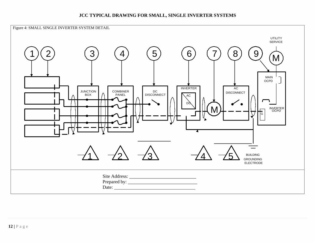
JCC TYPICAL DRAWING FOR SMALL, SINGLE INVERTER SYSTEMS
Figure 4: SMALL SINGLE INVERTER SYSTEM DETAIL
UTILITY
SERVICE
1 2 3 4 5 6 7 8 9 M
MAIN
OCPD
INVERTER AC
JUNCTION COMBINER DC DISCONNECT BOX PANEL DISCONNECT AC
DC
M INVERTER OCPD
G
1 2 3 4 5 BUILDING
GROUNDING
ELECTRODE
Site Address:
Prepared by:
Date:

13 | P a g e
JCC TYPICAL DRAWING FOR SMALL, SINGLE INVERTER SYSTEMS
NOTES AND SCHEDULES
O EQUIPMENT SCHEDULE TAG DESCRIPTION MODEL NUMBER NOTES
1
SOLAR PV MODULE
2
PV ARRAY
Module VOC V ISC R
3
J-BOX (IF USED)
4
COMBINER PANEL
5
DC DISCONNECT
6
DC / AC CONVERTER
Watts Volts Max per Branch
7 GEN METER (IF USED)
8 AC DISCONNECT (IF USED)
9
SERVICE PANEL
VAC A Main A Bus A Inverter OCPD
Δ CONDUIT AND CONDUCTOR SCHEDULE
TAG DESCRIPTION OR CONDUCTOR TYPE CONDUCTOR GUAGE NUMBER OF CONDUCTORS CONDUIT TYPE CONDUIT SIZE
1 USE-2 or PV WIRE
BARE COPPER EQ. GRD. COND. (EGC) N/A N/A
2 THWN-2 or XHHW-2 or RHW-2
INSULATED EGC
3 THWN-2 or XHHW-2 or RHW-2
INSULATED EGC
4 GROUNDING ELECTRODE COND.
5 SOLAR BACK-FED OCP AMPS N/A N/A
NOTES
1 All labels will be placed in accordance with NEC 690.
2 The sum of all supply breakers feeding a busbar / conductor cannot exceed 120% of the busbar / conductor rating.
3 Interconnection within the main panel shall be located at the opposite end of the buss from the main breaker.
4 DC conductors inside structure must be installed in a metal raceway.
5 AC and DC disconnects must be grouped.

JCC TYPICAL DRAWING FOR SMALL, MICRO INVERTER / AC SYSTEMS
14 | P a g e
Figure 5: JCC SMALL MICRO INVERTER / AC SYSTEM DETAIL
UTILITY
SERVICE
1 2 3 4 5 6 7 M
MAIN
OCP
D
JUNCTION COMBINER AC
BOX PANEL DISCONNECT
(IF USED)
G
1 2 3 4 5 6 BUILDING 7 GROUNDING ELECTRODE
Item 5: Combiner Panel may not require in Micro inverter Systems. Means shall be provided to disconnect all ungrounded dc conductors form all other conductors in a building or other structure. Per NEC 690.13
Site Address:
Prepared by:
Date:
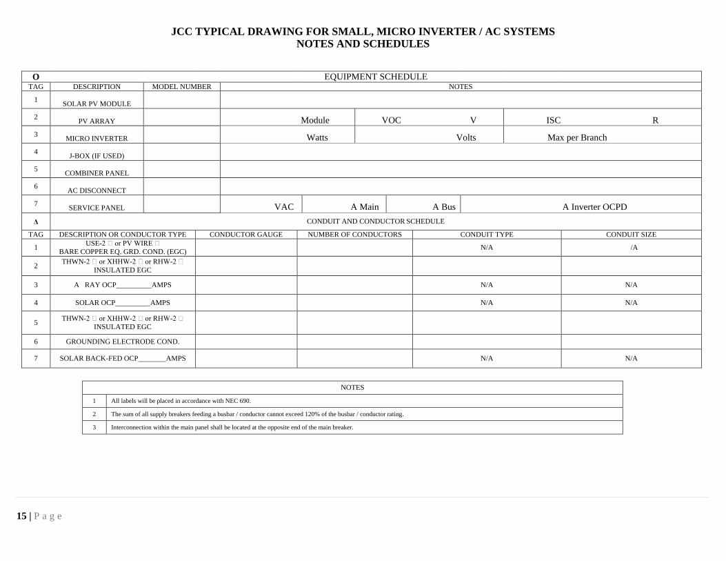
JCC TYPICAL DRAWING FOR SMALL, MICRO INVERTER / AC SYSTEMS
15 | P a g e
NOTES AND SCHEDULES
O EQUIPMENT SCHEDULE TAG DESCRIPTION MODEL NUMBER NOTES
1
SOLAR PV MODULE
2
PV ARRAY
Module VOC V ISC R
3
MICRO INVERTER
Watts Volts Max per Branch
4
J-BOX (IF USED)
5
COMBINER PANEL
6
AC DISCONNECT
7
SERVICE PANEL
VAC A Main A Bus A Inverter OCPD
Δ CONDUIT AND CONDUCTOR SCHEDULE
TAG DESCRIPTION OR CONDUCTOR TYPE CONDUCTOR GAUGE NUMBER OF CONDUCTORS CONDUIT TYPE CONDUIT SIZE
1 USE-2 or PV WIRE
BARE COPPER EQ. GRD. COND. (EGC) N/A /A
2 THWN-2 or XHHW-2 or RHW-2
INSULATED EGC
3 A RAY OCP AMPS N/A N/A
4 SOLAR OCP _AMPS N/A N/A
5 THWN-2 or XHHW-2 or RHW-2
INSULATED EGC
6 GROUNDING ELECTRODE COND.
7 SOLAR BACK-FED OCP AMPS N/A N/A
NOTES
1 All labels will be placed in accordance with NEC 690.
2 The sum of all supply breakers feeding a busbar / conductor cannot exceed 120% of the busbar / conductor rating.
3 Interconnection within the main panel shall be located at the opposite end of the main breaker.

16 | P a g e
SOLAR ENERGY SYSTEMS INSTALLATION CERTIFICATION Self-Certification Form for Rooftop Inspection. (Must have prior approval from JCC Building Official)
MASTER ELECTRICIAN
ELE PERMIT -
NAME:
(Type or Print)
MASTER #:
ADDRESS:
CLASS TEL #
GENERAL CONTRACTOR
BLD PERMIT -
NAME:
(Type or Print)
ADDRESS:
STATE REGISTRATION #:
CLASS TEL #
PLUMBING CONTRACTOR_
(Solar Water Heater)
PLB PERMIT -
NAME:
(Type or Print)
MASTER #:
ADDRESS:
CLASS TEL #
THE FOLLOWING BUILDING, PLUMBING AND/OR ELECTRICAL RELATED WORK WAS INSPECTED:
All work is installed per County Approved Plans and
manufacturer guidelines/installation instructions
Each Solar Panel is grounded using the supplied hardware
Listed rack system is attached to the structure per
manufacturer requirements
Conductor type
Solar Collector(s) are attached to the rack system per
manufacturer requirements
Conductor insulation
The Listed rack system is assembled per manufacturer
requirements
Tempature-derated ampacity calculations
All Solar Panels are UL Listed and are installed for their
specified use
Pressure terminals tightened to the recommended torque
specification
Pressure lugs or other terminals are listed for the environment
All penetrations through roof assembly are water and weather
tight
Inverter(s) are UL Listed
AC or DC grounding electrode conductors connected
properly
A minimum of a three feet perimeter is provided on the roof
between the solar panels and the eaves of the roof for access
Wet-rated conductors are used in conduits in exposed
locations
DATE OF INSPECTION(S): TIME OF INSPECTION(S):
A COPY OF THE REQUIRED BUILDING, ELECTRICAL AND/OR PLUMBING PERMIT WAS POSTED ON THE
CONSTRUCTION SITE AT THE TIME OF THIS INSPECTION. I CERTIFY THAT THE INSTALLATION MEETS ALL
REQUIREMENTS OF THE VIRGINIA UNIFORM STATEWIDE BUILDING CODE.
SIGNATURE OF MASTER ELECTRICIAN DATE
SIGNATURE OF MASTER MECHANICAL DATE
SIGNATURE OF AES CONTRACTOR DATE
PVInspPolicy.doc Rev. 05-19
SITE ADDRESS MAP PAGE
GRID #:
JOB NAME