jae 33fe - welcome to zippkits! the 33fe is the latest design of our very popular 21fe outrigger....
TRANSCRIPT

1
9477
JAE 33FE
Competition Electric Outrigger Hydroplane
Manufactured exclusively by Zippkits in the United States
Zippkits.com Toll Free (866) 922-ZIPP
Copyright ©2017 JMP Hobby Group LLC Indiana USA

2
The 33FE is the latest design of our very popular 21FE Outrigger.
The JAE outrigger series was conceived by IMPBA Hall of Fame members Rod Geraghty and
David Hall.
It was developed by Hall of fame member Ron Zaker, Jr. and Martin Truex, Jr.
This latest design was optimized for competition by Rod Geraghty and Martin Truex, Jr.
The only things that have been changed from the 21FE are the tub, sponsons, and ski…
It looks very similar, but this is an entirely new boat.
We have made great strides in functional design and manufacturing. We made this kit as easy
to build as we can, and added features to help insure a straight and square boat.
The recommended build and setup was determined after building and testing several models.
Build it the way we show, and set it up like we say, and you will have a great running boat “right
off the board” as they say.
The JAE 33FE has no bad habits, and as long as you don’t ask it to do something it was not
designed to do (sharp left turns, etc.), it absolutely will not do anything stupid. Ever.
This is a boat that you can trust and enjoy.
Thanks you very much for buying this kit, and remember that this is a HOBBY.
Have fun. If we can help you to that end, please contact us.

3
TOOLS AND MATERIALS NEEDED TO BUILD
Sanding blocks with 80 and 150 grit paper
220 and 400 grit wet or dry sandpaper
Drill with bits
Square
Flat file
FLAT Workbench
Titebond III wood glue or
Good quality 5 and 30 minute epoxy
Epoxy finishing resin or automotive clear
coat
Spring clamps, paper clamps, c clamps, etc.
Razor blade or X-Acto knife
Masking tape
Waxed paper
Wood filler
Primer
Paint

4
REQUIRED TO COMPLETE 36~40mm Inrunner (water cooled)
.187 Collet for motor (Zipp 3512)
180+ Amp Speed Control
.187 24 inch cable w/welded 3/16 stub shaft (Zipp
3502)
2 channel surface radio with 1 standard digital servo
Rudder pushrod (.055) with “Z” bend
1 pushrod seal (Zipp 3702)
.187 strut (Zipp 3495)
.187 drive dog (Zipp 3485)
1450 Mod prop (Zipp 4008)
Prop nuts (Zipp 3489)
Cable grease (Zipp 3532)
Rudder (Zipp 3483)
18 inch length of 1/4 brass tubing (pre-bent shaft tube
available)
Note that we have an Ultimate Hardware set available for the 33FE.
It includes everything you need to complete your boat, less electronics.

5
Kit Contents
1/16 Ply Parts
1/8 Ply Parts
Left sponson foam Right sponson foam

6
This kit is not hard to assemble, as all of the hard stuff has been done for you.
That is no excuse to do a poor job with assembly. The better you build this boat, the better it will
run. Often the difference between an excellent building job and a poor one is a simple sanding
block.
Take the time to read this entire manual, so that you are familiar with all the building steps and
their proper order. Take your time; make sure you understand everything before you do it and
you will be rewarded with an impressive running hull…
This kit is not a toy. Although R/C boating is a fun and rewarding hobby, it can be dangerous
if not done with common sense and safety in mind. Just about anyone should be able to
build this kit, but it should not be operated by children without close adult supervision.
A few words about glue:
When we build factory boats, we use the following:
We use and recommend Titebond III for general wood to wood construction. You can buy it
almost anywhere.
Titebond will only work on raw wood. It will not work on wood that has been sealed.
We use 5 and 30 minute epoxy for all other applications, especially non-wood joints (wood to
foam, etc.).
You can use 30 minute epoxy for 100% of the build if you wish.
The manufacturer assumes no liability for damages or other loss in the use of this product, as we have no control over the construction or end use of this product.

7
Let’s get started.
Tub
We will need the following parts:
Tub sides
Bulkhead 1 (BH1)
Bulkhead 2 (BH2)
Bulkhead 3 (BH3)
Aluminum motor Plate
Battery mount rails (B)
Transom (T)
Transom Doubler (TD)
Rudder Doubler (RD)
Nose Doubler (N)
Tub Bottom
FWD bottom (FWD)
We made the tub top and bottom a little wider than they need to be.
You can sand the edges now, before assembly. This will minimize any black streaking on the
tub sides from sanding the charred wood. Sand just enough to get the charred edges down to
clean wood.
Glue bulkheads 1 thru 3 in place on one tub side.
Glue the aluminum motor plate with epoxy. Work quickly.
Glue in the three battery mount rails.
Glue the other tub side to the bulkheads.
Make sure that the tub sides are glued correctly, and that no bulkheads overhang the sides.

8
Glue in the transom, and transom doubler. Make sure that the holes line up in the two parts, and
the tiny holes should be on the RIGHT side. Clamp T and TD together.
Note that the transom assembly should be all the way up, flush with the TOP, not the bottom.
Tightly tape around the tub at each bulkhead.
Note that the transom (and doubler) should be flush with the TOP of the tub, not the bottom.
Top

9
Glue the nose doubler and tape in place.
Allow to cure until the glue is very tacky, but still a little flexible. This will be about 30 minutes for
Titebond, 2 hours for (30 minute) epoxy.
We want to be able to skew the frame slightly, if needed, when we snap the bottom into place. If
the glue is fully cured, we may not get the bottom in place.
When the glue gets to that point:
Carefully remove the tape and prepare to glue in the tub bottom.
Test fit the tub bottom. It should fit in all slots, and not have any gaps. There is an overhang on
the rear. Do not sand this off! This is the finished length of the bottom.
Remove any glue blobs, or anything that prevents the bottom from snapping fully into place.

10
If all is well, glue the tub to the bottom. We like to use a jig to help keep everything straight, but
if you just use a square, and make sure that the sides don’t bow in or out, you will be fine.
Glue in the rudder doubler (RD) on the right side. This acts as a tripler for the rudder screws.
We provide two temporary sub-bulkheads (X) to use as spacers when gluing the top and bottom
to the tub. Use these, even if you use a jig, as they help prevent bowing of the sides.
Flip the tub upright on waxed paper.
Weight the tub so that the bottom stays in contact while the glue cures.
FWD Bottom
Sand a bevel at the front of the bottom sheet. This bevel matches the angle of the front sides. Glue the forward bottom (FWD) sheet in place, covering your bevel and extending any overhang to the front. Leave the rear overhang square. Do not sand flush. Tightly tape in place.

11
Deck Lips Glue the deck lips to the bottom of the deck, along the marked lines. Be very careful not to use
too much glue here.
We like to use medium CA glue and accelerator as follows:
Sand the little bumps off of the lips that were holding them together.
Spray the deck only in the areas of the lips with accelerator. Do not get any on the lips. Keep
them away from the accelerator mist.
Using a tiny little bead of medium CA on the lips only, glue the lips in place, lining them up to the
lines marked on the deck. You only get one chance, as once the glue touches the wood (treated
with accelerator), it is stuck.
Repeat on all lips. The deck is now ready for test fitting and sealing.
Ski
Clamp the ski sides to a straight piece of 1x lumber (3/4 inch thick). Cover the board with waxed
paper.
Make sure that the sides are aligned length and height wise. Double check this before gluing the
ski bottom on.

12
Begin by gluing the aft (long) ski bottom in place. This sheeting stops at the front, where the
angle changes. All excess overhang should be at the rear.
When cured, sand the bottom sheeting to a bevel, matching the angle of the front. This will
create a rear “step” that is one of the hallmarks of a record setting JAE design. This feature will
be used in several places on this boat, but the process and objective are all the same.
Glue on the forward (short) ski bottom. Cover the bevel that you sanded, and let any overhang
extend to the front. DO NOT sand any of the “step” leave it square and sharp.
When cured, sand the rear to match the rear angle. Sand the front overhang so that the ski will
sit flat, and the front of the sheeting should be sanded paper thin, to avoid a bump where the ski
begins.

13
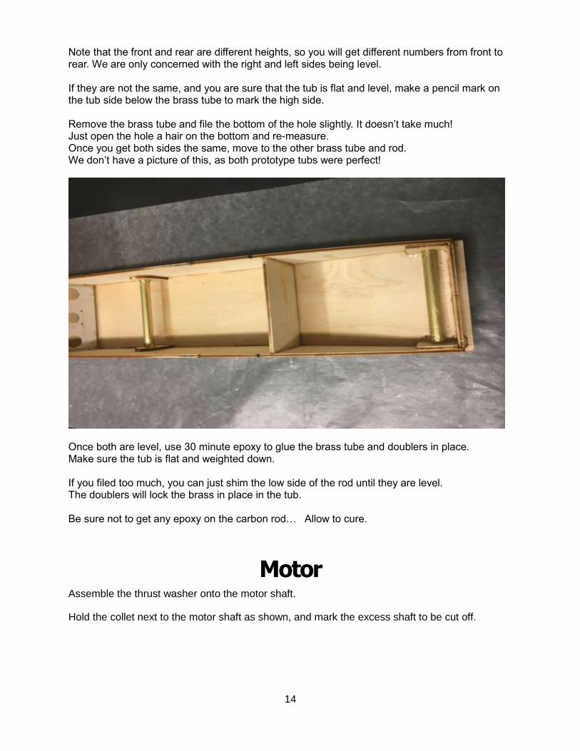
Back to the tub When cured, test fit the boom tube doublers, along with the brass sleeves. Forward doublers (FD) and aft doublers (AD). DO NOT GLUE YET.
Sand the last ¼ inch of both tubes with 80 grit paper. This helps the glue bite. Fit the doublers and tubes as shown. Glue from earlier may prevent them from fitting flat against the sides. If this happens, you may have to sand a small bevel on the forward doublers so that they fit flat. With both tubes and doublers in place, weight the tub to the bench so that it stays flat. Slip the carbon boom rods in place and center them. Measure from the bench to the boom rod, at the tips. What we want is both tips to be the same height from the bench (level, side to side).
14
Note that the front and rear are different heights, so you will get different numbers from front to rear. We are only concerned with the right and left sides being level. If they are not the same, and you are sure that the tub is flat and level, make a pencil mark on the tub side below the brass tube to mark the high side. Remove the brass tube and file the bottom of the hole slightly. It doesn’t take much! Just open the hole a hair on the bottom and re-measure. Once you get both sides the same, move to the other brass tube and rod. We don’t have a picture of this, as both prototype tubs were perfect!
Once both are level, use 30 minute epoxy to glue the brass tube and doublers in place. Make sure the tub is flat and weighted down. If you filed too much, you can just shim the low side of the rod until they are level. The doublers will lock the brass in place in the tub. Be sure not to get any epoxy on the carbon rod… Allow to cure.
Motor Assemble the thrust washer onto the motor shaft.
Hold the collet next to the motor shaft as shown, and mark the excess shaft to be cut off.
15
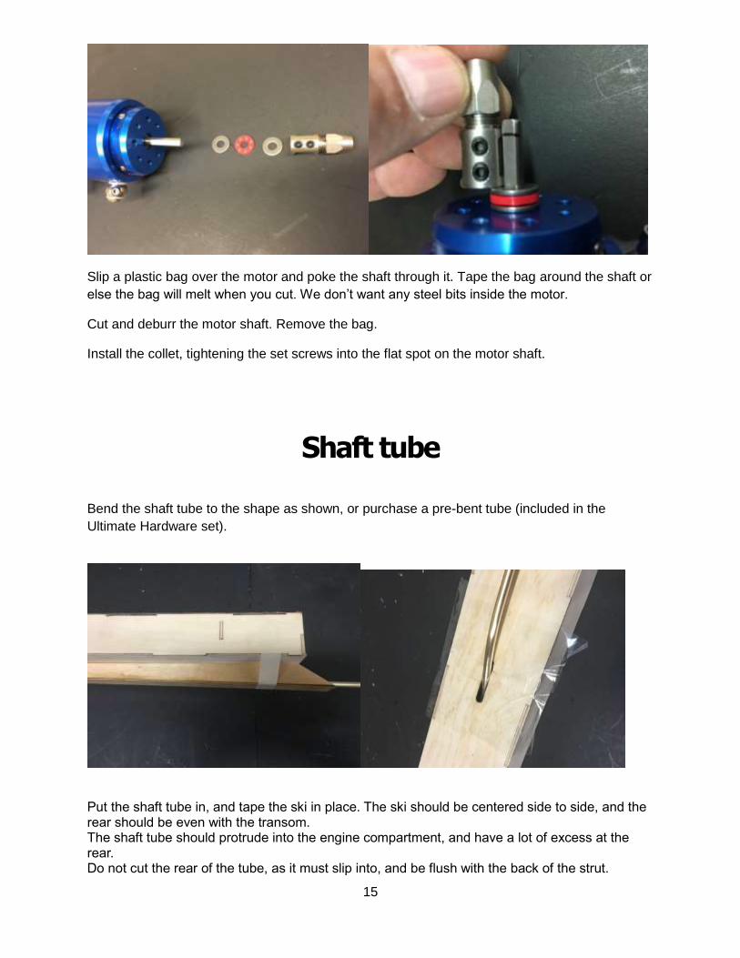
Slip a plastic bag over the motor and poke the shaft through it. Tape the bag around the shaft or
else the bag will melt when you cut. We don’t want any steel bits inside the motor.
Cut and deburr the motor shaft. Remove the bag.
Install the collet, tightening the set screws into the flat spot on the motor shaft.
Shaft tube
Bend the shaft tube to the shape as shown, or purchase a pre-bent tube (included in the
Ultimate Hardware set).
Put the shaft tube in, and tape the ski in place. The ski should be centered side to side, and the rear should be even with the transom. The shaft tube should protrude into the engine compartment, and have a lot of excess at the rear. Do not cut the rear of the tube, as it must slip into, and be flush with the back of the strut.

16
The shaft tube should end about ¼ inch from the motor collet. The ski should fit without hitting the shaft tube, if not; adjust the tube until it does. Once you are happy with the shaft tube, mark the locations of the bulkhead and tub bottom on the tube. Remove the ski and tube. Sand the tube in the areas you marked. Use 80 grit.
Re-install the shaft tube and tape around the bottom hole with clear packing tape. Tape the ski back in place. We like to put the motor and flex shaft in place to keep the tube aligned. Glue the shaft tube in place with 30 minute epoxy. Glue the tube at the bulkhead, as well as the bottom.
Allow to cure. Remove motor. Test fit the deck onto the tub. DO NOT GLUE. Make sure that it fits flat and snaps into the slots. If all is well, let’s get this thing sealed!

17
Sealing Once the bottom has cured, seal the inside of the tub. Also seal the bottom side of the deck. You can use epoxy finishing resin, or any epoxy compatible sealer. Don’t use polyester fiberglass resin. It is not compatible with epoxy glue.
Try not to get any sealer on the top of the tub, or in the slots for the deck. You will just have to sand it all off later. Use a rag to wipe any sealer off the top of the tub. Try not to get any sealer on the tops of the battery rails. It will make it difficult to glue in the battery tray later, Seal the underside of the deck as well. If you have any sealer left over, use it to seal the inside of the ski. Once the sealer is completely cured (overnight), use a razor blade or utility knife blade to scrape the sealer so that it is smooth, and there are no runs or bumps. Repeat the process so that everything except the deck has two coats of sealer. This is important, as one coat is not enough to be 100% water proof. The deck will get its second coat of sealer during installation. Once the sealer has cured, we need to make fillets at all joints that are on a seam. This is to keep any water from coming in at the seams. We like to mix up some 30 minute epoxy and brush a thick coat of epoxy in all corners and allow to cure.

18
Sponsons Let’s move on to the sponsons while the sealer is curing. Lay out all of the sponson parts, and make sure that you understand the assembly order before you start. Epoxy is impossible to remove from foam… The foam sponsons are sandwiched between ply plates, and sheeted with thin ply. *IMPORTANT* The sponson plates are different thickness. The 1/8 ply plates go INSIDE and the 1/16 ply plates go OUTSIDE. Be sure to make a right and left sponson as shown.

19
20
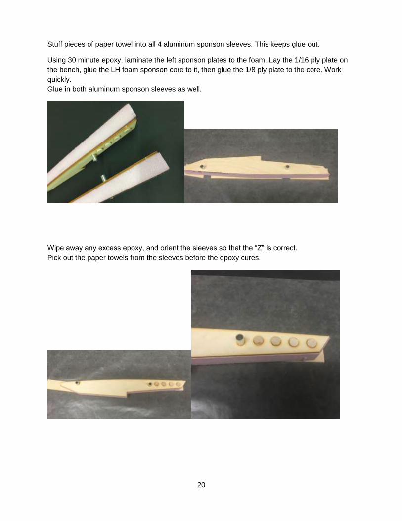
Stuff pieces of paper towel into all 4 aluminum sponson sleeves. This keeps glue out.
Using 30 minute epoxy, laminate the left sponson plates to the foam. Lay the 1/16 ply plate on
the bench, glue the LH foam sponson core to it, then glue the 1/8 ply plate to the core. Work
quickly.
Glue in both aluminum sponson sleeves as well.
Wipe away any excess epoxy, and orient the sleeves so that the “Z” is correct.
Pick out the paper towels from the sleeves before the epoxy cures.

21
Space the sponson off the bench with some scrap 1/8 ply, and add weight until cured.
Repeat for the RH sponson, and add the 4 wood dowels as well.
Allow to cure.
Sand the foam flush with the ply plates. Be sure that you sand a sharp inside corner at the back
of the ride surface. This is needed so that the 1/16 sheeting fits at a 90 degree angle.
See picture.
Begin sheeting with epoxy in the following order:
1 and 2. Tape in place and allow to cure. You can use 5 minute epoxy here.
Do both right and left.
22
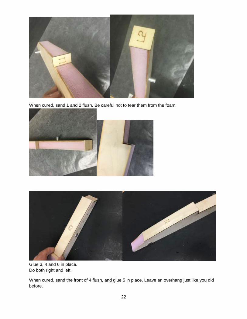
When cured, sand 1 and 2 flush. Be careful not to tear them from the foam.
Glue 3, 4 and 6 in place.
Do both right and left.
When cured, sand the front of 4 flush, and glue 5 in place. Leave an overhang just like you did
before.
23
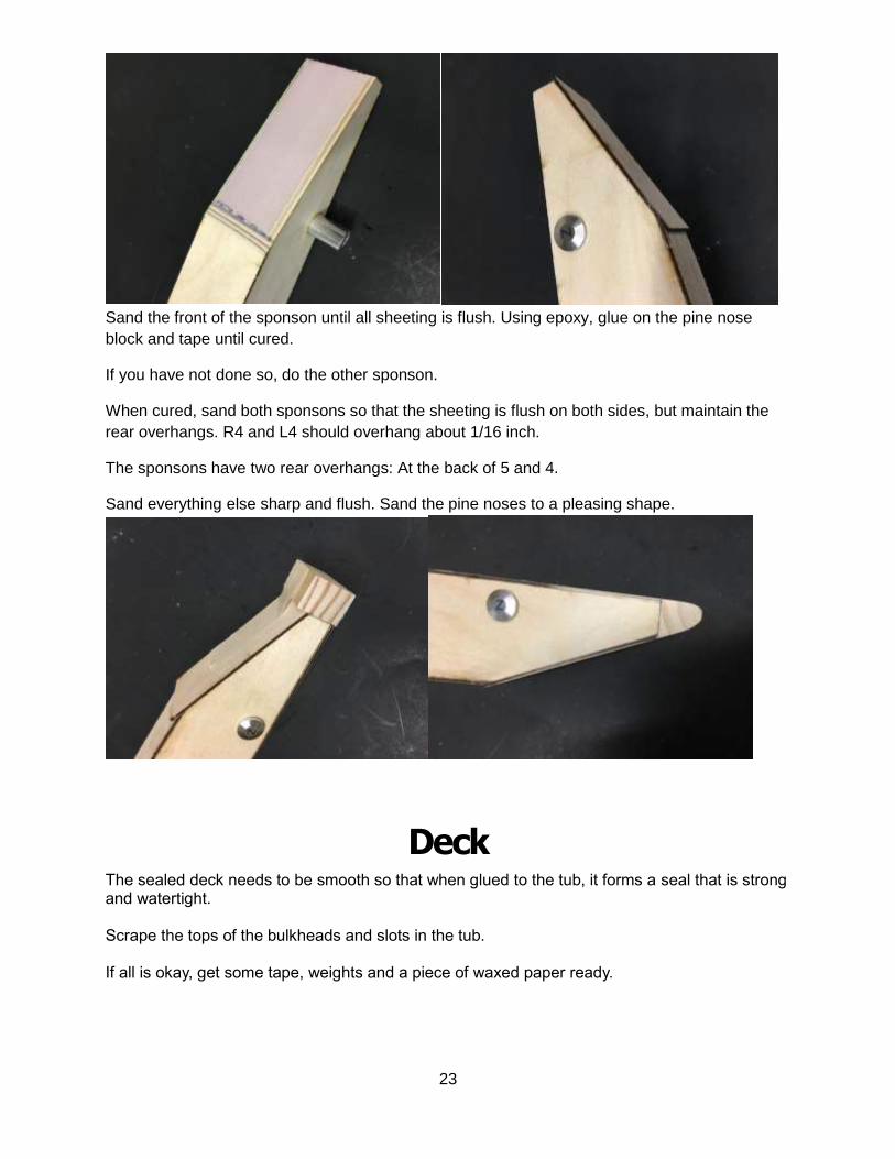
Sand the front of the sponson until all sheeting is flush. Using epoxy, glue on the pine nose
block and tape until cured.
If you have not done so, do the other sponson.
When cured, sand both sponsons so that the sheeting is flush on both sides, but maintain the
rear overhangs. R4 and L4 should overhang about 1/16 inch.
The sponsons have two rear overhangs: At the back of 5 and 4.
Sand everything else sharp and flush. Sand the pine noses to a pleasing shape.
Deck
The sealed deck needs to be smooth so that when glued to the tub, it forms a seal that is strong and watertight. Scrape the tops of the bulkheads and slots in the tub. If all is okay, get some tape, weights and a piece of waxed paper ready.

24
Use the provided sub-bulkheads (X) to brace the tub if needed. These prevent the tub from bowing during deck installation. Test fit the deck to the tub, and make sure that it fits fully into all slots. Mix up some 30 minute epoxy, and apply a (second) coat to the deck, bulkheads and top of the tub sides. Put the deck in place, and lay waxed paper over it. Use heavy weight (tool box, cinder block, etc.) to hold the deck in place. Tape the front end down tightly. Wipe away any excess epoxy and look all around to make sure that the deck is in complete contact all the way around. Double check this before you walk away. Allow to cure. When cured, flip the tub over and look at the deck to tub joint. It should be perfectly flush and sealed all the way around. Mix up some more 30 minute epoxy and use a small brush to paint a heavy coat into the corners where the deck meets the sides. Do the bulkheads too. Use a lot. Work quickly and flip the tub upside down so that the epoxy forms a nice fillet as it settles. Allow to cure. You just sealed the entire interior compartment at once. Once cured, sand the front of the tub flush, and glue the pine nose block in place. Use tape to secure.
When cured, plane and sand the block flush with the top and bottom, then round off.

25
Rudder Servo Assemble the aluminum servo mount and adjust for your servo. When happy, use thread locker on each of the 4 bottom screws. Do this one at a time. Sand the bottom of the aluminum servo mount with coarse (80) grit sand paper so that the epoxy will grip.
Bolt the motor into the aluminum motor plate as shown.

26
Assembly Finish drilling the holes for the strut and rudder in the transom. The rudder screw holes should be drilled with a 3/32 bit, and the strut bolt holes should use a 3/16 bit. Bolt the rudder in place, using the supplied #4 sheet metal screws.
Make sure that the rudder is 90 degrees to the bottom of the tub.
Bolt the strut bracket to the transom using the 6-32 blind nuts supplied with the strut.
Slip the strut onto the brass shaft tube and make the strut about level with the bottom of the
boat, and sitting on the ski. Mark the end of the strut on the tube.
Remove the strut and cut the brass tube about 1/16-1/8 inch shorter than your mark. We want
the ¼ brass shaft tube to stop short of the end of the strut, to allow space for the flare on the
strut bushing.
Do not glue the pushrod seal aluminum rings in place yet, but you can test fit it.
Put the “Z” bend onto the servo arm. Use the hole closest to the center of the servo. You may
need to open up the hole in the servo arm. Be careful not to create any slop.
Place the servo into the servo mount (without the top strap) and put it in the tub, guiding the
pushrod through the hole in the transom. Cut the pushrod so that it is about an inch longer than
it needs to be.
Slip the pushrod into the swivel connector (on the rudder). The servo should end up as far back
as you can get it, but still be able to get to the strap screws on top.
Try to center the pushrod in the transom hole.
Mark the location of the servo mount. Remove the servo mount and scrape or sand the tub
floor.
Remove the servo from the mount.
Use 30 minute epoxy to glue the servo mount in place. Align the mount to your marks.
Also glue in the battery tray, giving the entire tray a coating of 30 minute epoxy as you glue it in.
Allow to cure, but keep checking to be sure that nothing has moved.

27
Water Outlet
Decide where you want your water outlet to be.
We like to put it up high on the left side of the tub. That way, we can see the water exit when the
boat goes by.
Drill the hole for the water outlet with a ¼ inch drill.
Turn Fin Sharpen the turn fin on the outside (RH side) only. The bevel should be as wide as you can get
it. You should not be able to feel any transition from sharpened.
A perfect turn fin would have zero thickness at the leading edge, tapered to full thickness at the
trailing edge. This is not really possible, so make the transition as gentle as possible. We like
the leading edge to be about .020 inch or so. Any thinner and the 7075 aluminum starts to get
too thin and will ding easily..

28
Mark the center of the dowels on the inside of the RH sponson. Try to keep them close to the
center of the dowels.
Use a drill press if possible with a 5/32 bit, and drill halfway from one side, flip the sponson over,
and finish drilling from the other side.
Bolt the fin in place with the (4) 6/32x1-3/4 socket head screws, washers and nuts. The nuts
should be inside.
The fin should be fully adjustable for angle. Set it parallel with the sponson top and tighten the
screws.
Sealing Remove everything and sand the entire boat, including the tub, ski and sponsons.
Finish sanding with 220 grit and use wood filler to fix any gaps or imperfections.
Use the lightest color filler you can find.
The outside needs at least two coats of epoxy finishing resin or catalyzed clear coat.

29
Nitro version shown.
Allow each coat to fully cure before adding the next.
Scrape or sand between coats. Allow to fully cure.
At this point, the boat can be run without any more finish.
Sand the bottom of all running surfaces with 320 wet sandpaper WITH A BLOCK.
This will add a few mph. Only sand until the surface is smooth. It doesn’t take much.
If you desire to paint any part of your boat, now is the time to start primer and paint.
You must seal the paint with a catalyzed clear or epoxy clear, as tape will pull up almost any
other finish.
Final assembly Measure and mark the tub bottom so that the ski can be mounted in the center. The rear of the
ski should be even with the transom. It will be 1/16 inch forward of the rear bottom.
Using epoxy, glue the rear ski in place. Tape until cured.
Bolt the strut bracket in place on the transom. Be sure it is straight. Install the strut by slipping it
onto the brass tube. Use the included strut gauge (ST) to set the strut. The strut should be
sitting on the ski and parallel with the gauge.

30
Bolt the rudder in place using the sheet metal screws.
Radio Glue in the aluminum pushrod seal ring.
Center your transmitter steering trim and install rudder servo arm.
Be sure to install servo arm screw.
Install servo.
Push the rubber pushrod seal onto the aluminum ring and install pushrod.
Slip the pushrod into the swivel connector, center the rudder and tighten the set screw.
Use double sided tape to attach the receiver to the left side of the tub, in the servo bay.
Install the bulkhead fitting on the transom, as well as the water outlet.
Install the motor onto the motor plate, and plug in your speed control. The speed control should
be behind the motor.
Route your servo and ESC wires, and hook them up to the rudder.
Water Cooling Attach the silicone water line from the rudder to the bulkhead fitting, then to the ESC. From the
ESC to the motor, then out via the water outlet.

31
Sponsons Check both carbon boom tubes. You want one to be about 1/8 inch shorter than the other. The
short boom tube will be the front.
Slide the carbon boom tubes into the brass tubes in the tub. Slip an aluminum boom tube collar
onto each one, and place against the tub.
Slide both sponsons onto the boom tubes.
Drill a 1/8 hole through each aluminum sponson sleeve, through the carbon, and out the bottom.
Use a fast RPM and light pressure.
Secure with a 4-40 screw and nut. Repeat for other sponson sleeves.
Be sure that the tubes are bottomed in the sponson sleeves.
Center the sponsons on the tub, and toe in the RH sponson.
The LH sponson should be the same distance, front and rear, from the tub.
The RH sponson should be 1/8 to 3/16 inch closer at the front, for toe in.
Tighten the boom tube collars against the tub.
Flex Shaft Cut the 3/16 flex shaft as follows:
Slide the drive dog onto the shaft, then the prop. Leave about ½ inch of thread past the prop.
Tighten the set screw so that it makes an impression in the stub shaft.
Remove everything and grind a flat spot on the mark made by the set screw. This slit should be
at least 1/16 inch deep.
Reinstall the drive dog and use blue thread lock on it. Be sure that it is seated in the flat spot.

32
Dress the cut end of the cable if needed, so that you can slide it into the shaft tube and into the
collet.
Be sure that it is fully seated in the collet.
Measure the distance between the back of the strut and the drive dog. Subtract ¼ inch from
your measurement. This is how much to cut off the end of the flex cable.
You want to end up with a ¼ inch gap between the strut and drive dog when the shaft is fully
seated in the engine collet.
We wrap a little masking tape around the shaft, then mark the exact amount to be cut.
Measure twice, double check then cut. Use a cut off wheel. Dress the end of the cable when
done. Install the 10-32 locking prop nut.
Check the fit of the brass shaft bushing in the strut (with shaft tube inside). The bushing slips
inside of the ¼ inch OD brass shaft tube.
This should be a nice fit, and you should be able to spin it.
Grease the flex shaft fully, including the stub shaft and bushing.
Slip this back into the shaft tube, fully seat into the motor collet and securely tighten the collet.

33
Cowl Use a sharp knife to score the cut lines marked on the cowling. Bend and break the plastic on
the score lines. Sand the rounded corners. If painting the cowling, sand with 600-800 paper and
wash with soap and water before painting. Windshield decal is included.
Setup If you are using a 2200kv (or less) motor on 4S, use our Mod 1450 prop. Otherwise, start with a
small prop (440 2 blade) and check temps before going larger.
Make sure the prop is very sharp and well balanced.
Important- This boat must not have excessive rudder throw. Use no more than 1/4 inch of
movement each way. You will likely reduce the throw substantially more, but run it first.
All of the JAE hydros are hyper sensitive to rudder movement. It is no fun driving a boat that is
too sensitive.
Too much rudder throw will flip this boat. You don’t want to flip anything at 70+mph…
Make sure that the servo is not in a stalled condition, especially at the extremes of rudder throw.
Best to turn down your end points, and turn them up just enough to get the desired throw.
Make sure that the strut is sitting on the ski, and is perfectly parallel with the tub bottom.
Use the included strut gauge (ST). The bottom of the strut should be parallel with the tub
bottom.

34
Check the right sponson for 1/8-3/16 inch toe in. Toe out on the LH sponson is not a bad thing.
Running Install your battery on the tray, and use Velcro wrap to secure it.
The strut should never need adjustment.
Tips:
Fin adjustment:
Move the bottom of the fin forward to loosen the ride of the boat.
Move the bottom of the fin back to tighten the boats ride.
You will know when the fin is too far forward when one of the sponsons lifts in a turn. Move the
fin back until this stops. This is the preferred fin position.
Be sure the servo never binds and stalls.
Stalled digital servos will kill a battery in a few minutes, and may damage themselves and the
receiver. Things are different than in the old days with analog servos. Stall currents can exceed
10 amps easily today.
One point of advice:
There is a lot of information out there. If you need help, contact us. We know whatever you need
to know.
If you take advice from someone that does not own a great running JAE boat, consider the
value of that advice.
Please send us pictures of your completed 33FE. We really like pics of the boat sitting in the
water. Links to videos are welcome as well.
Note that replacement parts are always available from us. If you make a mistake while building,
just contact us for free replacement kit parts.
Thanks again, and if we can help you enjoy RC boating in any way, please contact us!

35