jackson - cojcd.org library items/consent decree/wwtp...wwtp operations and maintenance program 5...
TRANSCRIPT


jACKSON The City of
Wastewater Treatment Plant
Operations and Maintenance Program
Department of Public Works
Wastewater Infrastructure Redevelopment Program
May 31, 2014

City of Jackson
Wastewater Infrastructure Redevelopment
Program
Wastewater Treatment Plant Operations and Maintenance Program May 31, 2014
Prepared for: City of Jackson
Department of Public Works
P.O. Box 17
Jackson, MS 39205-0017
Prepared by: WEI/AJA LLC
143A LeFleurs Square
Jackson, MS 39211


iii
Wastewater Treatment Plant
Operations and Maintenance Program
Contents
1.0 Introduction ....................................................................................................................... 1
1.1 Consent Decree Requirements .............................................................................................. 1
1.2 Report Organization .................................................................................................................. 3
2.0 Jackson Wastewater Treatment Plants ..................................................................... 5
2.1 Savanna Street WWTP ............................................................................................................. 5
2.2 Presidential Hills WWTP ........................................................................................................ 7
2.3 Trahon/Big Creek WWTP ...................................................................................................... 7
2.4 WWTP Contract Operations .................................................................................................. 8
3.0 Equipment, Parts and Material Inventory ............................................................... 9
3.1 UWS-MS Operational Support Systems.. .......................................................................... 9
3.2 Inventory Control ...................................................................................................................... 11
3.3 Vendor Services .......................................................................................................................... 11
3.4 Management of Critical Spare Parts ................................................................................... 12
4.0 Solids Management ........................................................................................................... 25
4.1 Sludge Sources ............................................................................................................................ 25
4.2 Waste Activated Sludge ........................................................................................................... 25
4.3 Storm Cell Sludge ....................................................................................................................... 27
5.0 Preventative Maintenance Program ........................................................................... 29
5.1 UWS-MS Preventative Maintenance Program ............................................................... 29
5.2 O&M Staffing and Resource Commitments ..................................................................... 30
5.3 WWTP PM Program .................................................................................................................. 39
5.4 Predictive Maintenance .......................................................................................................... 43
5.5 Corrective Maintenance .......................................................................................................... 43
5.6 Emergency Maintenance ........................................................................................................ 47
5.7 Operation and Maintenance Program Summary .......................................................... 47

iv
List of Tables Table
3-1 United Water O&M Glossary ...................................................................................................... 10
3-2 Jackson WWTPs Master Spare Parts and Equipment List ............................................. 14
3-3 Savanna Street WWTP Item Transaction Log Report ..................................................... 16
3-4 Savanna Street WWTP Inventory Adjustment Report ..................................................... 17
3-5 Savanna Street WWTP Vendor Master List .......................................................................... 19
3-6 Critical Equipment Identification Criteria ............................................................................. 21
3-7 Critical Equipment Rating ............................................................................................................ 22
3-8 Daily Critical Equipment Status ................................................................................................. 23
5-1 UWS-MS Work Order Procedures ............................................................................................. 42
5-2 Work Order Statistics ..................................................................................................................... 46
List of Figures Figure
2-1 Savanna Street WWTP Schematic ............................................................................................. 6
2-2 Savanna Street WWTP Aerial View .......................................................................................... 6
2-3 Presidential Hills WWTP Schematic ........................................................................................ 7
2-4 Trahon/Big Creek WWTP ............................................................................................................ 8
3-1 eRPortal CMMS Spare Parts Tracking ..................................................................................... 15
3-2 eRPortal CMMS Inventory Reports .......................................................................................... 15
3-3 eRPortal Inventory Item Reordering Screen ........................................................................ 18
3-4 Oracle Enterprise Management System Vendor Data ...................................................... 20
4-1 Savanna Street WWTP Storm Cells .......................................................................................... 27
5-1 Jackson eRPortal Computerized Maintenance Management System ......................... 31
5-2 United Water-MS O&M Staff Organization ............................................................................ 32
5-3 UWS-MS Job Description – Maintenance Technician ........................................................ 33
5-4 UWS-MS Job Description – Electrical Technician ............................................................... 34
5-5 UWS-MS Job Description – O&M Technician ........................................................................ 35
5-6 Operations Staff Training Requirements ............................................................................... 37
5-7 Maintenance Staff Training Requirements ........................................................................... 38
5-8 Example PM Schedule .................................................................................................................... 40

v
5-9 Work Order Generation and Tracking .................................................................................... 41
5-10 Predictive Maintenance Example – Thermographic Inspection .................................. 44
5-11 Corrective Maintenance Work Flow ........................................................................................ 45
Appendix
A Savanna Street WWTP Sludge Management Plan .............................................................. A-1
B Wastewater Treatment Plant Standard Operating Procedures
Belt Filter Press .................................................................................................................... B-1
Dewatering Centrifuge ...................................................................................................... B-13
Wet Weather Operating Plan .......................................................................................... B-19
Plant Power Failure ............................................................................................................ B-37
Control Panel Damage ....................................................................................................... B-39


City of Jackson WWTP Operations and Maintenance Program
1
1. 0 Introduction
The City of Jackson entered into a Consent Decree with U.S. EPA on March 1, 2013 to
address inadequacies of the City’s wastewater collection and treatment facilities. This
report describes the Wastewater Treatment Plant Operations and Maintenance
Program used by the City and its contract operator, United Water Services Mississippi, LLC
(UWS-MS). The report fulfills the requirements set forth in Consent Decree § VI (D)-42.
1.1 Consent Decree Requirements As stated in the Consent Decree, the Wastewater Treatment Plant (WWTP) Operations and
Maintenance Program shall contain the following, at a minimum:
1. Equipment, Parts, and Material Inventory. The City shall inventory its WWTPs’
operating equipment and materials and evaluate the impacts of the loss of use or failure
of each major system component. The City shall develop an inventory control system
which shall have the capability of tracking spare parts use and inventory, as well as
generating inventory replenishment needs reports. The City’s inventory control system
shall also include the following elements:
1) Prioritization of WWTP components as critical, semi-critical, or noncritical which
shall allow the City to focus its maintenance capabilities and spare parts inventories
on the WWTP components and potential failures that would have the greatest
impact on treatment capacity, Prohibited Bypassing, and NPDES Permit compliance.
2) Identification of critical spare parts and materials, and procedures to ensure that
these parts and materials are stored and maintained in inventory at the WWTP.
3) A list of where the remaining spare parts may be secured to enable the repair or
replacement of such equipment in a minimum amount of time and to ensure proper
operation of the WWTP.
4) Tracking of spare parts use and inventory, as well as generating inventory
replenishment needs reports.
2. Sludge Processing and Removal. Not inconsistent with the requirements of the MDEQ
Agreed Order I, the maintenance program shall include sludge removal procedures,
schedules, and standard practices for the WWTPs and from any storage lagoons, wet
weather storage cells, equalization ponds, or any other wet weather storage facility that
is, or is planned for use by, a WWTP.
3. Preventive Maintenance. The City shall develop and implement a preventive
maintenance system for the WWTPs to ensure that preventive and corrective

City of Jackson WWTP Operations and Maintenance Program
2
maintenance is conducted and that equipment integral to proper operation and
maintenance, treatment units, and tanks are maintained so as to achieve compliance
with the NPDES permit. The preventive maintenance system shall include, at a
minimum, the following:
1) Identification of equipment used in the treatment of wastewater liquids and
biosolids.
2) Identification of the standard procedures to conduct preventive maintenance of
such WWTP equipment.
3) Identification of the frequency and duration of preventive maintenance necessary to
ensure that all WWTP equipment is maintained in such a way so as to achieve
compliance with the NPDES permit.
4) Identification of the training and education required for maintenance personnel to
perform the standard preventive maintenance procedures.
5) Procedures for recognition of indicators that corrective maintenance on WWTP
equipment is necessary.
6) Procedures for the generation of work orders for preventive and corrective
maintenance of WWTP equipment.
7) Procedures for the generation of purchase orders associated with preventive and
corrective maintenance of WWTP equipment.
8) Examples of the types of reports and forms which will be used in implementing the
preventive maintenance system.
9) A system for tracking preventive and corrective maintenance activities and histories
including the generation of summary reports each month that identify major
equipment failures occurring in the previous month and the end-of-month status of
preventive and corrective maintenance work orders issued or outstanding in the
previous month for equipment.
10) Procedures to ensure that failures of equipment and/or loss of power supply during
abnormal and emergency conditions are corrected in a timely fashion so as to limit
the downtime of the facility or component.

City of Jackson WWTP Operations and Maintenance Program
3
1.2 Report Organization An overview of the City of Jackson wastewater treatment plants is given in Section 2,
together with a general description of the United Water Services Mississippi, LLC operations
and maintenance program. Section 3 describes the computerized maintenance management
system software used by UWS-MS, and the associated equipment, parts, and materials
tracking procedures. Section 4 describes new standard operating procedures developed for
maintenance of the storm cells (equalization basins) at the Savanna Street WWTP to avoid
excess sludge accumulation, and for maintaining proper sludge inventories within the main
treatment plant unit processes. The WWTP Preventative Maintenance program is described
in Section 5, including standard operating procedures and a summary of the qualifications
and training requirements for O&M staff. Implementation of the program is discussed in
Section 6.

City of Jackson WWTP Operations and Maintenance Program
4

City of Jackson WWTP Operations and Maintenance Program
5
2.0 Jackson Wastewater Treatment Plants
The City of Jackson operates three wastewater treatment plants (WWTPs). A brief
description of each facility is provided below.
2.1 Savanna Street WWTP The Savanna Street WWTP serves most of the population in the City together with flow
from three satellite utility authorities. These contribute wastewater flow from western
Rankin County, southern Madison County, and the Pearl River Valley Water Supply District
(Barnett Reservoir area). The Savanna Street plant has a permitted capacity of 46 MGD
summer and 60 MGD winter. Annual flows to the plant currently average about 45 MGD.
The Savanna Street WWTP is a conventional activated sludge facility without primary
clarifiers. Flow is received through the 50-ft deep 96-in diameter West Bank interceptor.
The West Rankin force main also discharges to the West Bank interceptor upstream of the
influent pump station. Major unit processes are:
Influent trash racks.
Influent pump station.
Headworks with two mechanically cleaned bar screens, two screenings compactors, two
vortex grit removal units, two grit pumps, and two grit washing units.
Bioselector basin to promote good sludge settling.
Ten aeration basins with fine bubble tube diffusers, each 2.56 MG in volume.
Aeration blower facility with four single stage blowers.
Five 140-ft diameter secondary clarifiers.
Two return sludge pump stations.
Two waste activated sludge pumps.
Chlorine storage and feeding equipment for disinfection.
Chlorine contact channel.
Sulfur dioxide storage and feeding equipment for dechlorination.
Effluent pump station for use when river levels are high.
Outfall to the Pearl River.
Three excess flow equalization basins.
Two aerobic digesters.
Two gravity sludge thickeners.
Thickened sludge holding tank.
Three two meter width belt filter presses for sludge dewatering.
A schematic of the Savanna Street WWTP is shown in Figure 2-1. An aerial view of the plant
is shown on Figure 2-2.

City of Jackson WWTP Operations and Maintenance Program
6
Figure 2-2
Savanna Street WWTP Aerial View
Figure 2-1
Savanna Street WWTP Schematic

City of Jackson WWTP Operations and Maintenance Program
7
Figure 2-3
Presidential Hills WWTP Schematic
2.2 Presidential Hills WWTP The 0.75 MGD Presidential Hills WWTP was constructed as a conventional aerated lagoon
system followed by effluent filtration and chlorine disinfection. A new sequencing batch
reactor (SBR) treatment plant is nearing completion of construction and will startup in mid-
2014. When the new plant is on-line the aerated lagoons will be used as flow equalization
basins. The SBR was constructed in response to new, more stringent permit limits for
nutrients. A process schematic of the new plant is shown on Figure 2-3.
2.3 Trahon/Big Creek WWTP The 4 MGD Trahon/Big Creek WWTP uses the oxidation ditch process. Principal unit
processes are:
Influent pump station
Mechanical bar screens
Aerated grit chamber with grease removal
Two Carousel® oxidation ditches
Two secondary clarifiers
Chlorine contact basin
Aerobic digestion
The plant does not have any on-site mechanical sludge thickening or dewatering capability.
An aerial photo of the plant is shown on Figure 2-4.

City of Jackson WWTP Operations and Maintenance Program
8
Figure 2-4
Trahon/Big Creek WWTP
2.4 WWTP Contract Operations The City of Jackson has contracted operation and maintenance of the wastewater treatment
plants and all pump stations to United Water Services Mississippi LLC (UWS-MS). The
company is a subsidiary of the global private O&M conglomerate, Suez Environnement.
United Water has 2,350 employees in the U.S., operates 90 municipal systems, and is one of
the largest private O&M companies. UWS-MS has 42 full time staff in Jackson to operate the
City’s wastewater treatment plants and pump stations.

City of Jackson WWTP Operations and Maintenance Program
9
3.0 Equipment, Parts and Material Inventory
A characteristic of a quality WWTP O&M program is a good system of managing the
inventory of operating equipment, spare parts, and materials. A description of the inventory
control system used by the City, through its professional contract operator UWS-MS, is
described in this Section.
3.1 UWS-MS Operational Support Systems United Water O&M staff employs several resources to manage inventories required in
WWTP operations. These resources are briefly described below. Table 3-1 defines some of
the key elements and terminology used by UWS-MS in operating and maintaining the plants.
Oracle Enterprise Performance Management
UWS-MS uses an Oracle Enterprise Performance Management (EPS) system to provide
integrated planning, analysis, accounting, and reporting tools to aid O&M staff in proper
operation and management of their assigned facilities and systems. The Oracle EPS has
computer modules that can assist with:
Planning
Budgeting
Performance monitoring
Progress tracking
Communications management
Scheduling and forecasting
Cost management
Reporting
The EPS is used in operation and management of all facilities assigned to UWS-MS, including
the wastewater treatment plants.
eRPortal Asset and Maintenance Management System
UWS-MS has adopted a standardized computerized maintenance management system
(CMMS) at the facilities they operate. This system is developed around the eRPortal CMMS
software platform, which has been fully implemented by UWS-MS in Jackson. The eRPortal
software provides enterprise asset management and materials management applications
designed to optimize operations, maintain assets and infrastructure, and manage all related
materials, resources, and logistics. The software is user friendly and is easily configurable to
each individual facility. eRPortal CMMS effectively manages both planned and unplanned
work order logistics. The system is designed for operational flexibility and can be adapted
to specific work environments and workflows. eRPortal also supports GASB34 accounting
standards and EPA CMOM regulations with “cradle-to-grave” asset tracking capabilities and
environmental protection compliance. These capabilities include tracking warranties and

City of Jackson WWTP Operations and Maintenance Program
10
ACRONYM / ABBREVIATION DESCRIPTION
ACTION LOG A document, which is an output from a meeting, that defines
the action items that needs to be accomplished, who is
responsible, and when it will be completed.
ASR Area Status report. Weekly progress reports made by
workstream leaders to the Project Manager
BACKLOG The total open balance of a set of data. Sometimes refers to
only the past due balance. i.e., The total # of work orders or
labor hours, by craft, required to complete all outstanding
work. May also be the total amount of unshipped orders, or
outstanding PM’s to be completed
CM Corrective Maintenance
COUNTDOWN TO MILESTONES Countdown to List of weekly scheduled activities, which are required
Milestones
DAILY REVIEW MEETING A review of the current days performance. Purpose is to
review KPI’s and develop action plans to improve
performance
DMAIC Design, Measure, Analyze, Improve, Control
DWOR Daily/Weekly Operating Report- This departmental
performance report is used to record the planned versus
actual performance on a daily and weekly basis of the key
performance indicators and is the source document used to
generate improvement actions
EFFICIENCY A measure of how the available resource is being used.
Efficiency compares planned to actual hours for a job.
(performance to a standard)
KPI Key Performance Indicator - a means to measure the
performance against a planned level of performance of an
activity or process. Ex.-OEE, Backlog, Units Per Hour, % PM
completed.
KPI TREE The linking of Business imperatives throughout the
organization. A KPI Tree cascades each of the desired
outcomes to the lowest level for which a KPI can be
managed.
MCRS Management Control Reporting System is a closed-loop
system, comprised of information, documents and meetings,
which is used to deliver quantifiable business performance
improvements
MILESTONES Key deliverables of a project. Typically spaced in 8 week
increments which defines the systems, tools, methods, and
related improvements to be delivered by workstream
MWOR Monthly, Weekly Operating Report. Key performance report
used to assess current performance and implement Root
Cause Corrective Actions. Reviewed during Management
Review Meeting
NVA Non Value Added - time which does not add value to a task
and does not help us achieve our desired goal
PdM Predictive Maintenance
PM Preventive Maintenance - maintenance activity performed on
a repetitive and scheduled calendar basis. PM is used to
extend the life or maintain the effectiveness of an asset.
PROCESS MAPPING Process mapping is a tool designed to map out systems and
processes in order to clarify, train or improve business
processes
WIP Work in progress
WO Work order. Vehicle used to assign work to an individual or a
manufacturing order to replenish stock
WORK REQUEST A work request is the first step in creating a work order.
Once the work request is reviewed and approved it becomes
a work order
United Water Services Mississippi LLC
Savanna Street WWTP
OPERATIONS & MAINTENANCE GLOSSARY
Table 3-1

City of Jackson WWTP Operations and Maintenance Program
11
labor for budgeting purposes, monitoring safety hazards for work orders, making condition-
based assessments, and tracking assets. The system is specifically designed to simplify
maintenance and compliance tasks for water and wastewater treatment plants.
Operations Data Management
UWS-MS collects data from a variety of sources that is used to monitor and plan facility
operations. These include instrumentation readouts delivered through SCADA, manually
recorded data points collected by operators as part of daily operations, and analytical data
generated by on-site and off-site laboratories. The operations data is managed locally using
a custom designed Excel-based spreadsheet system.
3.2 Inventory Control UWS-MS maintains a detailed inventory control system with the capability to track usage
and determine replenishment needs. Complete inventories are kept of spare parts,
materials, equipment, and some consumables. An example of the UWS-MS inventory master
list is shown on Table 3-2.
Spare parts are managed using the eRPortal CMMS. Figure 3-1 and Figure 3-2 illustrate the
inventoried parts, parts classification, and spare parts tracking reports maintained on
eRPortal.
Separate records are kept of spare parts inventory quantity changes and maintenance
activities performed, as shown on the Item Transaction Log Report (Table 3-3). Inventory
change adjustments are tracked in more detail as shown on Table 3-4. Some of the
inventory records kept are redundant and carry over from before eRPortal was
implemented in 2011. Through these multiple inventory tracking methods, UWS-MS has a
continuous accurate picture of the state of the current spare parts, materials, and
equipment inventory. eRPortal is also used to generate automated item reordering requests
when the quantity of the inventoried item falls below the “Must Have” quantity. An example
of the item reordering screen from eRPortal is shown on Figure 3-3. A purchase order
requisition is subsequently generated to replenish the item.
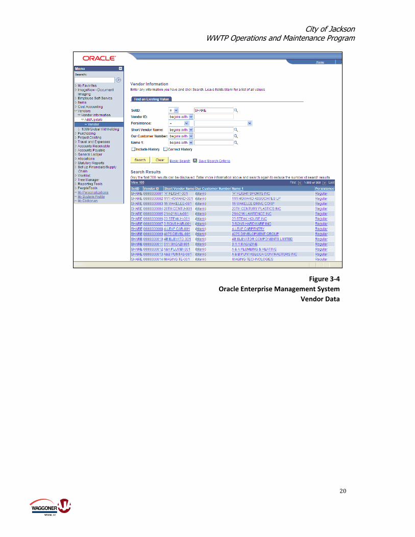
3.3 Vendor Services UWS-MS maintains an up-to-date list of vendors and suppliers able to furnish all spare
parts, materials, and equipment required by the plant. Complete records are kept on all
vendors whose products and services are required to operate and maintain the plants.
Having access to and good relations with a wide variety of outside vendors is an operational

City of Jackson WWTP Operations and Maintenance Program
12
necessity. Detailed vendor contact information is maintained on a master list as shown on
Table 3-5. An excerpt from the Oracle Enterprise Performance Management system
illustrating some of the vendor data recorded is shown on Figure 3-4. The UWS-MS vendor
list is extensive, and as a result a wide variety of suppliers, repair service companies, and
other businesses are available to provide any needed good or service required by the plants.
3.4 Management of Critical Spare Parts A key concept in a strategic asset management program is the criticality of assets.
Consequently, UWS-MS has a defined procedure for identification and tracking of critical
plant components and equipment. The list of critical equipment is developed through
analysis of probability and consequences of failure. This list is maintained and utilized by
UWS-MS to effectively sustain the project assets.
Failure of critical equipment may result in a potential:
Unsafe or hazardous work environment
Environmental excursion or violation
Contract compliance – Quality
Contract compliance – Throughput
Major cost impact
Client community nuisance
Six different criticality ratings are used to prioritize WWTP components and potential failures that would have the greatest impact on treatment capability. These ratings are:
CRITICAL/Emergency – Highest priority; break schedule for immediate repair
CRITICAL/High Importance –Higher priority; break schedule for immediate repair
CRITICAL/Significant – Higher priority; break schedule for immediate repair
NONCRITICAL/Concern – Priority; begin repair work within 24 hours
NONCRITICAL/Minor Impact – Lower priority; schedule to repair within a week
NONCRITICAL/No impact – Lowest priority; schedule repair in next weekly
commitment meeting

City of Jackson WWTP Operations and Maintenance Program
13
Each critical item is assigned an Importance Ranking and a Priority Ranking as shown on
Table 3-6. For each critical component, the importance ranking is determined by
considering potential impacts to safety, environment, quality, wastewater throughput,
operations costs, and degree of nuisance. An excerpt from the critical equipment list for the
Trahon-Big Creek WWTP showing the priority and ranking for each is given on Table 3-7.
The status of critical equipment requiring maintenance action is tracked daily. An example
of the Daily Critical Equipment Status Report is shown on Table 3-8. This report is used to
insure that critical spare parts and materials are stored and maintained in inventory at the
WWTP.
In summary, UWS-MS maintains a capable and efficient inventory management system. No
changes appear to be required to the current inventory tracking system for equipment,
materials, or critical spare parts.

City of Jackson WWTP Operations and Maintenance Program
14
Table 3-2
Jackson Wastewater Treatment Plants
Master Spare Parts and Equipment List

City of Jackson WWTP Operations and Maintenance Program
15
Figure 3-1
eRPortal CMMS Spare Parts Tracking
Figure 3-2
eRPortal CMMS Inventory Reports

City of Jackson WWTP Operations and Maintenance Program
16
0.00
1.00 1.00
0.00
-1.00 1.00
0.00
1.00 1.00
0.00
-1.00 1.00
0.00
1.00 1.00
0.00
-1.00 0.00
0.00
1.00 1.00
0.00
0.00 11.00
0.00
1.00 1.00
0.00
0.00 1.00
-1.00 0.00
0.00
1.00 1.00
0.00
-1.00 0.00
0.00
Report Filters: Active Items Only
Item Number Date/Time User ID Order # Description On Hand
000003 UW 105 Oil Change
2/1/2013 4:14:52 PM erussell Create New Item
2/1/2013 4:14:52 PM Add Location Maint
2/1/2013 4:14:53 PM erussell Item Restock Change
2/1/2013 4:17:36 PM 200309-1-1 New Issue Line
000004 M&O Door Install
2/4/2013 2:26:37 PM Add Location Maint
BELT0022 Bottom Belt 2.2x16.3
2/1/2013 3:53:57 PM erussell Create New Item
2/4/2013 2:26:37 PM erussell Item Restock Change
2/4/2013 2:28:47 PM 200310-1-1 New Issue Line
2/1/2013 3:55:53 PM erussell Create New Item
2/1/2013 3:55:53 PM Add Location Maint
2/1/2013 3:55:54 PM erussell Item Restock Change
United Water Services Mississippi LLC
Item Transaction Log Report
Savanna Street WWTP
Qty
2/1/2013 3:53:58 PM Add Location Maint
2/1/2013 3:53:58 PM erussell Item Restock Change
2/1/2013 4:05:56 PM 200308-1-1 New Issue Line
BELT0023 Top Belt 2.0x15.7
2/4/2013 2:26:36 PM erussell Create New Item
PARTS0006 1 1/2" BALL VALVE - 1 1?2" PVC BALL VALVE
11/2/2012 9:24:04 AM system Change Product Class
PARTS1002 Vacuum Truck Cylinder Repair
11/29/2012 2:04:45 PM erussell Create New Item
11/29/2012 2:04:45 PM Add Location Maint.
11/29/2012 2:04:45 PM erussell Item Restock Change
11/29/2012 2:05:01 PM erussell Change
11/29/2012 2:06:33 PM 200301-1-1 New Issue Line
PARTS1003 Incline Conveyor Roller Repair
12/4/2012 10:38:48 AM erussell Create New Item
12/4/2012 10:38:49 AM Add Location Maint.
12/4/2012 10:38:49 AM erussell Item Restock Change
12/4/2012 10:54:42 AM 200302-1-1 New Issue Line
PARTS1004 Incline drive roller repair
12/4/2012 11:01:43 AM erussell Create New Item
Table 3-3

City of Jackson WWTP Operations and Maintenance Program
17
Date New Qty UM UM
7/8/10 EA EA
7/8/10 EA EA
9/7/11 EA EA
9/7/11 EA EA
9/9/11 EA EA
3/26/09 EA EA
3/26/09 EA EA
4/28/10 EA EA
8/20/08 EA EA
8/20/08 EA EA
10/22/09 EA EA
7/8/10 EA EA
1/21/10 EA EA
10/2/08 EA EA
10/1/08 EA EA
Inventory Adjustment Report
Cost Adjustment
ItemNumber / Description OldQty Change(+) Change(-) OldCost
BELT0002 14.00 14.00 6.7100 7.2500
0.00
8.19
AF0010 0.00 0.00 3.5600 4.9500
0.00 0.00
NewCost
AF0007 9.00 9.00 0.5900 1.5000
0.00
4.1500
0.00 0.00
ICPS second Floor Vent Fan
BELT0007 0.00 0.00 5.8000 58.0000
Cedar Creek Netzsch Pumps
BELT0004 0.00 0.00 3.8000
7.56
54 inch drive belt for the effluent blowers
BELT0003 4.00 4.00 25.0000 27.5000
0.00 10.00
0.00
BELT0034 0.00 0.00 48.0000 49.0000
0.00 0.00
BELT0016 0.00 0.00 4.3600 3.7500
0.00
0.00 0.00
BELT0007 0.00 0.00 5.8000 58.0000
0.00 0.00
BOLT0003 0.00 0.00 0.0000 14.5000
0.00
0.00
BOLT0002 86.00 86.00 0.0000 1.5000
0.00 129.00
BELT0042 0.00 0.00 7.0000 7.5000
0.00
0.00
BRNG0003 0.00 0.00 0.0000 4.5900
0.00 0.00
BOLT0010 0.00 0.00 0.0000 0.5000
0.00
0.00
BOLT0004 0.00 0.00 0.0000 1.0000
0.00 0.00
Table 3-4
United Water Services Mississippi LLC
Savanna Street WWTP

City of Jackson WWTP Operations and Maintenance Program
18
Figure 3-3
eRPortal Inventory Item Reordering Screen

City of Jackson WWTP Operations and Maintenance Program
19
Name/Alias ID Contact Status
AAACOOPE 601-936-9600 Active
AAMCOTRA Active
ACEBOLTS Active
ACME Active
Suite 30 413-739-0299
West Springfield, MA 01089
ADVANCEA Active
AGRIDYNE Active
AIRCONTR Active
AIT Active
PO Box 412756 283-3287
KCMO, MO 64141
ALLISCHA Jackson, MS 601-922-8725 Active
AMERICAN PO Box 11236 Birmingham, Al 3 205-251-4000 Active
205-252-6300
APPLEWHI Active
APPLIEDI Active
AQUAAERO 6306 N. Alpine Road Rockford, 815-654-2501 Active
ARENDERP Active
ARGUSANA PO Box 13842 Jackson, MS 3923 601-957-2676 Active
ASHBROOK Active
ATLASDOO 116 Truman Drive Eddison, NJ 201-572-5700 Active
AUTHORIZ Active
AUTOMATE Active
AUTOZONE 3256 Terry Road Jackson, Ms 601-371-1033 Active
BACKFLOW Active
BARNHART Active
BELTWARE Active
BIG10TIR Active
BIGJOEMF Active
BLAINEST Active
BLAINSAN 601-892-1741 Active
Vendor Master List
Savanna Street WWTP
United Water Services Mississippi LLC
Phone/Fax/EMailAddress
AAA Cooper Clayton 124 Interstate Drive Richland
Updated: 6/7/2013
Aamco Transmission Kelty 943 South State Street Jackso 601-948-7343
Ace Bolt & Screw Mike PO Box 22533 Jackson, MS 3922 601-355-3448
Acme Products Doug Ansuini 59 Interstate Drive 413-739-7390
Advance Auto Parts Robert 3318 Terry Road Jackson, MS 3 601-373-5185
Agri Dyne Harvey PO Box 458 Bolton, MS 39041 601-866-2233
Air Contractors Donna PO Box 6843 Jackson, MS 39282 601-373-9296
Applied Industrial Technologie Dave Brody 2029 Wyandotte 421-0407
Allis Chalmers
American Carbon Industries
Applewhite Equipment & Supply Lloyd Highway 49 South Florence, MS 601-845-1964
Applied Industrial Jeff 531 Highway 49 South Richland 601-939-1417
Aqua Aerobics Systems
Arender Plumbing Supplies Fred 2025 Highway 80 West Jackson, 601-355-2243
Argus Analytical,
Ashbrook Corp. Brian 11600 East Hardy Houston, TX 800-362-9041
Atlas Door Corp.
Authorized Appliances Tina 943 South Gallatin Street Jac 601-354-5367
Automated Power Kelly 4364 Mangum Drive Pearl, MS 3 601-936-4900
AutoZone
Backflow Controls Roger Potts Camp, MS 662-3339007
Barnhart Drake 246 North Pearson Road Jackso 601-664-3005
Belt Warehouse Larry 1631 Westhaven Boulevard Jack 601-922-2700
Big 10 Tires Inside Sales 1027 Terry Road Jackson, MS 3 601-352-6546
Big Joe Mfg.Co.
Blaine's Trailer Inside Sales 1271 New Highway 49 South Ric 601-939-1935
Blain Sand & Gravel
Table 3-5
City of Jackson WWTP Operations and Maintenance Program
20
Figure 3-4
Oracle Enterprise Management System
Vendor Data

City of Jackson WWTP Operations and Maintenance Program
21
CRITICAL EQUIPMENT IDENTIFICATION CRITERIA
QUESTION TO ANSWER FOR RANKING CRITERIA : Failure of equipment may result in potential _________________
CONTRACT COMPLIANCE -Operations & Maintenance
Quality Throughput Operating Costs Nuisance
5 = Fatality
5 = Severe
Environmental damage
that impacts off-sight
5 = Effluent Quality
cause the entire
process to be shutdown
5 = Shutdown entire
operational process
5 = O&M cost impact of
>$25k
5 = Nuisance causing
litigation
4 = Disabling Injury
4 = Severe
Environmental damage
that impacts on-sight
4 = Effluent Quality
does not meet
Contractual
requirements
4 = Unable to meet
rated capacity
throughput contractual
requirements
4 = O&M cost impact of
>$10k to <$25k
4 = Nuisance causing
media complaints
3 = OSHA Reportable
3 = Environmental
Regulatory Violation or
Excursion
3 = Effluent Quality
does not meet Clients
expectations
3 = Unable to process
wet weather W W TP
flow(s) and maintain
normal sludge inventory
level
3 = O&M cost impact of
>$5k to < $10k
3 = Nuisance causing
compliants from local
community groups
2 = Minor Injury - reportable
to Hotline
2 = Minor environmental -
reportable to Hotline
2 = Effluent Quality affecting
operational process
2 = Unable to meet rated
capacity requiring diversion
2 = O&M cost impact of
>$1k to <$5k
2 = Nuisance causing
inidividual public compliants
1 = Near Miss Reportable1 = Minor environmental non-
reportable impact
1 = Miinor mpact to process
Quality
1 = Minor impact affecting
operational process
1 = Minor O&M cost impact
<$1k
1 = Minor on-property
nuisance
0 = No Injury 0 = No environmental Impact0 = No impact to Effluent
Quality
0 = No impact to process to
maximum capacity0 = No O&M cost impact 0 = No nuisance impact
CRITERIA RANKING PRIORITY
CRITICAL - Emergency 5 A
CRITICAL - High Importance 4 A
CRITICAL - Significant 3 A
NONCRITICAL - Concern 2 B
NONCRITICAL - Minor Impact 1 B
NONCRITICAL - No Impact 0 C
Table 3-6
higher priority - break schedule for immediate repair
priority - begin repair within 24 hours
lower priority - schedule repair within a week
lowest priority - schedule repair in next weekly commitment meeting
higher priority - break schedule for immediate repair
United Water Services Mississippi LLC
Safety, Environmental and Operations Risk Matrix
SAFETY ENVIRONMENTAL
highest priority - break schedule for immediate repair
PRIORITY COMMENTS

City of Jackson WWTP Operations and Maintenance Program
22
Equipment# Description Type Prioirty SAFETY ENVIRONMENT QUALITY THROUGHPUT OPS COSTS NUISANCE RANK
T-ADMIN BUILDING STRUCTURE BUILDING C 0 0
T-AERATOR 1 NORTH WEST AERATOR AERATOR A 3 3
T-AERATOR 1 CONTROLS NORTH WEST AERATOR CONTROLS ELECTRICAL A 3 3
T-AERATOR 1 MOTOR NORTH WEST AERATOR MOTOR MOTOR A 3 3
T-AERATOR 2 NORTH EAST AERATOR AERATOR A 3 3
T-AERATOR 2 CONTROLS NORTH EAST AERATOR CONTROLS ELECTRICAL A 3 3
T-AERATOR 2 MOTOR NORTH EAST AERATOR MOTOR MOTOR A 3 3
T-AERATOR 3 SOUTH WEST AERATOR AERATOR A 3 3
T-AERATOR 3 CONTROLS SOUTH WEST AERATOR CONTROLS ELECTRICAL A 3 3
T-AERATOR 3 MOTOR SOUTH WEST AERATOR MOTOR MOTOR A 3 3
T-AERATOR 4 SOUTH EAST AERATOR AERATOR A 3 3
T-AERATOR 4 CONTROLS SOUTH EAST AERATOR CONTROLS ELECTRICAL A 3 3
T-AERATOR 4 MOTOR SOUTH EAST AERATOR MOTOR MOTOR A 3 3
T-ALARM SYSTEM CL2/ SO2 ALARM SYSTEM ALARMS B 2 2
T-AUTO SAMPLER EFF EFFLUENT AUTO SAMPLER SAMPLER B 2 2
T-AUTO SAMPLER INF INFLUENT AUTO SAMPLER SAMPLER B 2 2
T-BACKFLOW PREVENTER PLANT BACKFLOW PREVENTERS BACKFLOW A 5 5
T-BAR SCREEN 1 EAST BAR SCREEN BAR SCREEN A 4 4
T-BAR SCREEN 1 CONTROL EAST BAR SCREEN CONTROL ELECTRICAL A 4 4
T-BAR SCREEN 1 MOTOR EAST BAR SCREEN MOTOR MOTOR A 4 4
T-BAR SCREEN 2 WEST BAR SCREEN BAR SCREEN A 4 4
T-BAR SCREEN 2 CONTROL WEST BAR SCREEN CONTROL ELECTRICAL A 4 4
T-BAR SCREEN 2 MOTOR WEST BAR SCREEN MOTOR MOTOR A 4 4
T-BAR SCREEN BLOWER BAR SCREEN VENTILATION BLOWER A 4 4
T-BAR SCREEN CONVEYOR BAR SCREEN CONVEYOR CONVEYOR A 4 4
T-BAR SCREEN VAVLES BAR SCREEN VALVES VALVES A 4 4
T-BLOWER 10 HP 1 10 HP BLOWER BLOWER B 2 2
T-BLOWER 10 HP 1 CONTROL 10 HP BLOWER CONTROLS ELECTRICAL B 2 2
T-BLOWER 10 HP 1 PIPING 10 HP BLOWER PIPING/ VALVES PIPING B 2 2
T-BLOWER 10 HP 2 10 HP BLOWER BLOWER B 2 2
T-BLOWER 10 HP 2 CONTROL 10 HP BLOWER CONTROLS ELECTRICAL B 2 2
T-BLOWER 10 HP 2 PIPING 10 HP BLOWER PIPING/ VALVES PIPING B 2 2
T-BLOWER 50 HP 1 50 HP BLOWER BLOWER A 3 3
T-BLOWER 50 HP 1 CONTROL 50 HP BLOWER CONTROLS ELECTRICAL A 3 3
T-BLOWER 50 HP 1 MOTOR 50 HP BLOWER MOTOR MOTOR A 3 3
T-BLOWER 50 HP 1 PIPING 50 HP BLOWER PIPING/ VALVES PIPING A 3 3
T-BLOWER 50 HP 2 50 HP BLOWER BLOWER A 3 3
T-BLOWER 50 HP 2 CONTROL 50 HP BLOWER CONTROLS ELECTRICAL A 3 3
T-BLOWER 50 HP 2 MOTOR 50 HP BLOWER MOTOR MOTOR A 3 3
T-BLOWER 50 HP 2 PIPING 50 HP BLOWER PIPING/ VALVES PIPING A 3 3
T-BOOSTER PUMP 1 BOOSTER PUMP #1 PUMP A 5 5
T-BOOSTER PUMP 2 BOOSTER PUMP #2 PUMP A 5 5
T-BOOSTER PUMP 3 BOOSTER PUMP #3 PUMP A 5 5
T-BOOSTER PUMP PIPING PIPING/ VALVES PIPING A 5 5
T-CL2 PIPING CL2 PIPING/ VALVES PIPING A 5 5
T-CL2 REGULATOR CL2 FEED REGULATOR REGULATOR A 5 5
T-CL2 SCALES CHLORINE CYLINDER SCALES SCALES A 5 5
T-CL2/ SO2 BUILDING STRUCTURE BUILDING B 2 2
T-CLARIFIER 1 CLARIFIER #1 CLARIFIER A 3 3
T-CLARIFIER 1 RAKE LOWER RAKE RAKE A 3 3
T-CLARIFIER 1 RAKE GEARBOXRAKE GEARBOX GEARBOX A 3 3
T-CLARIFIER 1 RAKE MOTOR RAKE DRIVE MOTOR MOTOR A 3 3
T-CLARIFIER 1 SKIM GEARBOX SKIMMER ARM GEARBOX GEARBOX A 3 3
T-CLARIFIER 1 SKIM MOTOR SKIMMER ARM MOTOR MOTOR A 3 3
T-CLARIFIER 1 SKIMMER SKIMMER ARM SKIMMER A 3 3
T-CLARIFIER 2 CLARIFIER #2 CLARIFIER A 3 3
T-CLARIFIER 2 RAKE LOWER RAKE RAKE A 3 3
T-CLARIFIER 2 RAKE GEARBOXRAKE GEARBOX GEARBOX A 3 3
T-CLARIFIER 2 RAKE MOTOR RAKE DRIVE MOTOR MOTOR A 3 3
T-CLARIFIER 2 SKIM GEARBOX SKIMMER ARM GEARBOX GEARBOX A 3 3
T-CLARIFIER 2 SKIM MOTOR SKIMMER ARM MOTOR MOTOR A 3 3
T-CLARIFIER 2 SKIMMER SKIMMER ARM SKIMMER A 3 3
T-COMPUTERS COMPUTERS COMPUTER C 0 0
T-CONTACT CHAMBER STRUCTURE/ VALVES/ PIPING TANK A 3 3
T-DEGRITTER 1 CYCLONE DEGRITTER CONVEYOR B 2 2
T-DEGRITTER 2 CYCLONE DEGRITTER CONVEYOR B 2 2
T-DEGRITTER AUGER 1 CYCLONE DEGRITTER AUGER AUGER B 2 2
T-DEGRITTER AUGER 2 CYCLONE DEGRITTER AUGER AUGER C 0
T-DEGRITTER BUILDING STRUCTURE BUILDING A 2 2 4
T-DEGRITTER CONVEYOR CYCLONE DEGRITTER CONVEYOR CONVEYOR B 2 2
T-EMERGENCY LIGHTING ALL BUILDINGS SAFETY A 3 3
T-FIRE EXTINGUISHER PLANT FIRE EXTINGUISHERS FIRE EXTINGUISHERA 3 3
T-FLOW METER EFFLUENT EFFLUENT FLOW METERS FLOW METER A 3 3
United Water Services Mississippi LLC
Trahon-Big Creek WWTP
Critical Equipment Rating
Table 3-7

City of Jackson WWTP Operations and Maintenance Program
23
Date
Equipment Total
Must
have Available O/S Date
Days
O/S
Cell 3 Recovery Pump 1 1 1
Cell 5 Recovery Pump 1 1 1
West Rankin Gates 2 2 2
Trash Bar Racks 4 4 4
Raw Sewage Pumps 4 4 2 2/13/2013 443
Influent Flow Meter 1 1 1
Emergency Generators 3 2 2
Mobile Generator 1 1 1
Gate Drill for Manual Operation 1 1 1
Generator for Gate Drill 1 1 1
SCADA Computer 1 1 1
Influent Sampler 1 1 1
Mecahnical Bar Screens 2 1 1 4/10/2013 387
Grit Removal System 2 2 2
Anoxic Tanks 2 2 2
Aeration Tanks 10 10 10
Aerobic Digesters 2 2 2
Digester Thickeners 2 2 2
Aeration Blowers 4 2 3
Clarifiers 5 5 5
Calrifiers 1-4 RAS Pumps 4 3 2 6/7/2013 329
Clarifier 5 RAS pumps 2 1 2
Chlorine Leak Alarms 1 1 1
Chlorine Regulators 32 16 16
Chlorine Feeders 2 2 2
Chlorine Gas Mixer 1 1 0
Plant Water Pumps 3 2 2
Plant Water Filter 2 2 2
Turbine Effluent Pumps 2 1 1
Effluent Screw Pumps 4 4 4
SO2 leak alarms 1 1 1
SO2 Regulators 8 8 8
SO2 Feeders 2 2 2
SO2 gas mixers 2 2 2
Effluent Flow Meter 1 1 1
Effluent Sampler 1 1 1
Diversion Flow Meter 1 1 1
Waste Sludge Pumps 2 1 2
Waste Sludge Pumps Flow Meters 2 1 2
Thickened Sludge Pumps 2 2 2
Thickened Sludge Pumps Flow Meters 2 2 2
Sludge Mixing Tank 1 1 1
Sludge Mixing Tank Mixer 1 1 1
Sludge Feed Pumps 3 3 3
Sludge Grinders 2 2 2
BFP Polymer Feed Systems 3 3 3
Plant Water Booster Pumps 1 1 1
Belt Filter Presses 3 3 3
Dewatering BFB -Centrifuge Rented 2 2 2
Sludge Conveyors 3 3 3
Sludge Loader 1 1 1
Duplex Lift Stations 2 2 2
Quadraplex Lift Stations 4 3 4
Critical Equipment Availability 83%
DAILY CRITICAL EQUIPMENT STATUS
Savanna Street WWTP
Comments
5/2/2014
Parts arrived 2/18/13 Waiting for Shutdown/ Injection System in use
POR for New #4 5/16/13
Parts ordered for the South Screen
United Water Services Mississippi LLC
Table 3-8
#1 down for 7 years/Repaired gearbox Install started 1-13-13
Parts on order for #3 Pump / #4 out for Quotes/Repairs
#3 is deadlined

City of Jackson WWTP Operations and Maintenance Program
24

City of Jackson WWTP Operations and Maintenance Program
25
4.0 Solids Management
United Water has in place procedures for storage, handling, and processing of sludge from
the three wastewater treatment plants. The solids management procedures, schedules, and
standard practices are described in this section.
4.1 Sludge Sources Each of the WWTPs produces sludge that must be properly managed. The sludge streams
consist of:
Presidential Hills WWTP – A new 0.75 MGD mechanical treatment plant using the
sequencing batch reactor process is starting up in mid-2014. Waste activated sludge
generated by the SBR will be conveyed to the Savanna WWTP for processing.
Trahon/Big Creek WWTP – The existing 4 MGD oxidation ditch plant produces waste
activated sludge which is trucked in liquid form to the Savanna WWTP for processing.
Current flows to the plant average about 2 MGD. About 6,500-gal, or one truck load, of
WAS is hauled to the Savanna plant daily.
Savanna WWTP – Sludge is generated at the Savanna plant from two main sources:
1. Waste activated sludge – Currently averaging about 900,000 gal/day of 1.4%
secondary sludge for an average plant flow of about 45 MGD. This plant does not
have primary clarifiers.
2. Storm cell storage – Any excess wet weather flow diverted to the storm cell flow
equalization basins for temporary storage contains some solids. Over time these
solids will accumulate in the storm cells and will require removal. A project to
remove sludge from the Savanna WWTP storm cells was completed in April
2014.
As noted above, all wastewater sludge generated in the City of Jackson and contributing
satellite communities is centrally handled at the Savanna WWTP.
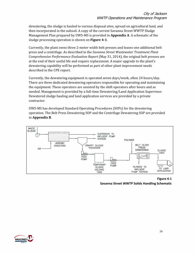
4.2 Waste Activated Sludge The Savanna WWTP is a conventional activated sludge plant without primary clarifiers. A
portion of the waste activated sludge must be removed from the process daily. The WAS is
sent to aerobic digesters to allow some solids reduction through destruction of a portion of
the volatile solids. In the digesters, the sludge is further thickened by intermittent cycles of
settling and decanting of supernatant. From the digesters, the sludge flows to two gravity
sludge thickeners to provide additional solids concentration. Thickened WAS is then
pumped to a sludge holding tank. Feed pumps transfer the thickened sludge to belt filter
presses and a centrifuge where polymer is added and the sludge is dewatered. After
City of Jackson WWTP Operations and Maintenance Program
26
Figure 4-1
Savanna Street WWTP Solids Handling Schematic
dewatering, the sludge is hauled to various disposal sites, spread on agricultural land, and
then incorporated in the subsoil. A copy of the current Savanna Street WWTP Sludge
Management Plan prepared by UWS-MS is provided in Appendix A. A schematic of the
sludge processing operation is shown on Figure 4-1.
Currently, the plant owns three 2-meter width belt presses and leases one additional belt
press and a centrifuge. As described in the Savanna Street Wastewater Treatment Plant
Comprehensive Performance Evaluation Report (May 31, 2014), the original belt presses are
at the end of their useful life and require replacement. A major upgrade to the plant’s
dewatering capability will be performed as part of other plant improvement needs
described in the CPE report.
Currently, the dewatering equipment is operated seven days/week, often 24 hours/day.
There are three dedicated dewatering operators responsible for operating and maintaining
the equipment. These operators are assisted by the shift operators after hours and as
needed. Management is provided by a full-time Dewatering/Land Application Supervisor.
Dewatered sludge hauling and land application services are provided by a private
contractor.
UWS-MS has developed Standard Operating Procedures (SOPs) for the dewatering
operation. The Belt Press Dewatering SOP and the Centrifuge Dewatering SOP are provided
in Appendix B.

City of Jackson WWTP Operations and Maintenance Program
27
Figure 4-2
Savanna Street WWTP Storm Cells
4.3 Storm Cell Sludge During periods of high wastewater flows, excessive flow beyond the main plant treatment
capacity is diverted to the storm cell flow equalization basins. These three cells have a
combined storage capacity of 171 MG. A 100 MGD storm water pump in the influent pump
station is used to divert the flow. Additionally, a second diversion point to the storm cells
can be used for flows from the Rankin County force main. After peak flows recede, a return
line from Cell 3 is used to return stored flow to the West Bank Interceptor for treatment by
the plant. Arrangement of the three storm cells is shown on Figure 4-1.
UWS-MS has developed a new SOP for management of wet weather flows and the storm cell
diversion process. The Savanna Street WWTP Wet Weather Operating Plan is included in
Appendix B.
A project to remove accumulated sludge from the storm cells was completed in April 2014.
Following successive diversions of future excess wet weather flows, sludge will again slowly
accumulate in the storm cells over time. In the future, sludge levels will be monitored and
measured on an annual basis. Accumulated sludge will be removed from the storm cells as
needed, estimated at approximately every 5 years. Sludge removed from the storm cells will

City of Jackson WWTP Operations and Maintenance Program
28
be disposed of off-site by land application or landfilling, depending on the sludge
characteristics.

City of Jackson WWTP Operations and Maintenance Program
29
5.0 Preventative Maintenance Program
United Water has an active a Preventative Maintenance Program in force for the wastewater
treatment plants and pump stations operated and maintained for the City of Jackson. The
purpose of the PM program is to provide proactive preventative and predictive
maintenance to minimize required corrective maintenance. The UWS-MS Preventative
Maintenance Program is described in this section.
5.1 UWS-MS Preventative Maintenance Program The City of Jackson has contracted operation and maintenance of the wastewater treatment
plants and all pump stations to United Water Services Mississippi. The City still provides
maintenance services for the gravity sewers, but essentially all mechanical and electrical
equipment maintenance in the system is the responsibility of UWS-MS. As one of the largest
private O&M companies, UWS-MS has adopted a standardized computerized maintenance
management system (CMMS) at the facilities they operate. This system is developed around
the eRPortal CMMS software platform, which has been fully implemented by UWS-MS in
Jackson.
The eRPortal CMMS incorporates the following features.
A powerful preventative maintenance (PM) scheduling module with the flexibility to
control when work orders should be triggered. For triggered PM’s, the work order
includes procedures, parts, personnel assignments, skill/labor-code requirements, and
other required data. Information displayed on the work order is only what is actually
needed to complete the assignment.
A work-order management module that allows tracking of time, materials, schedules,
dates, and responsiveness.
A supervisory control and data acquisition (SCADA) interface that permits operators to
view upcoming and open work orders and full details of work-order history without
leaving their operating consoles. They also can quickly enter work-order requests that
send out e-mail notifications.

City of Jackson WWTP Operations and Maintenance Program
30
The SCADA interface also allows run time-based preventive maintenance work-order
triggers. The interface can also generate condition- and predictive-based orders that
incorporate any combination of sensors (vibration, temperature, or pressure) or
equipment usage being monitored.
Parts tracking and management functionality that identifies, allocates, and tracks
replacement parts required for repetitive tasks. Preferred vendors, blanket purchase
orders, and procurement contracts can be managed from within the system. Extensive
item properties can be tracked, including multiple cost methodologies, serialization/lot
numbers, weight, description, type, class, and dimension. The system can utilize existing
barcode IDs or create new ones on-demand or at time of purchase order receipt.
Web browser-enabled architecture with complete supply chain connectivity. This
allows the software to interface via the Web or other connectivity formats with all
internal and external systems at key touch points where information exchange is
critical.
The following sections provide documentation how the UWS-MS maintenance staff and the
eRPortal CMMS facilitate completion of required PM activities. A screenshot of the eRPortal
CMMS home screen is shown on Figure 5-1.
5.2 O&M Staffing and Resource Commitments
O&M Staff Organization
UWS-MS has a single maintenance department responsible for maintaining the City’s three
wastewater treatment plants and all of the pump stations. An organization chart for the
UWS-MS O&M staff is shown on Figure 5-2.

City of Jackson WWTP Operations and Maintenance Program
31
Figure 5-1
Jackson eRPortal Computerized Maintenance Management System

City of Jackson WWTP Operations and Maintenance Program
32
Figure 5-2
UWS-MS O&M Staff Organization
Figure 5-2
United Water – MS O&M Staff Organization

City of Jackson WWTP Operations and Maintenance Program
33
Figure 5-3
UWS-MS Job Description –Maintenance Technician
Maintenance Staff Qualifications
The UWS-MS Maintenance Department has 13 full time maintenance positions. These
individuals are responsible for conducting all PM activities required on the electrical,
mechanical, and physical facilities and equipment. Performing PM is an integral part of their
job, and is a defined role in UWS-MS maintenance staff job descriptions. Example UWS-MS
maintenance job descriptions are shown on Figure 5-3 and Figure 5-4.

City of Jackson WWTP Operations and Maintenance Program
34
Figure 5-4
UWS-MS Job Description – Electrical Technician
Operations Staff Qualifications
The United Water Maintenance Department has 34 full time positions assigned to
operations and maintenance of the WWTPs and pump stations. An example UWS-MS O&M
technician job description is shown on Figure 5-5.

City of Jackson WWTP Operations and Maintenance Program
35
Figure 5-5
UWS-MS Job Description – O&M Technician
POSITION: Operations & Maintenance (O&M)
Technician III
DATE: April 2013
DEPARTMENT: UWSI Jackson MS Wastewater Facility APPROVAL:
LOCATION: Jackson MS
REPORTS TO: Department Manager
Job Code: Department: Position No: FLSA Status:
Summary:
Performs, with minimal supervision, a variety of operational and maintenance tasks relevant to the
safe and reliable operations of water and/or wastewater treatment facilities ensuring operation in
compliance with state and federal regulations.
Dimensions / Supervisory Responsibilities:
Team Leader for 3-5 team members with responsibility for planning and directing work assignments,
under the supervision of the Department Manager or the Operations Manager.
Education/Equivalent:
High School Diploma or equivalent is required, Associate’s Degree in a related environmental or
technical field is preferred. Experience may be substituted for formal education.
Mid level certification required to operate, service, maintain, and/or repair industrial equipment
as found in treatment processes and/or at the facility being operated and in compliance with state
environmental regulations.
Valid driver’s license in state of residence is required and must meet risk management guidelines.
May require CDL and the ability to learn and perform tasks as outlined on C&D chart.
Work Experience Needed:
Minimum of 4 to 7 years experience in water and/or wastewater treatment industry while
holding certification.

City of Jackson WWTP Operations and Maintenance Program
36
Figure 5-5 (continued)
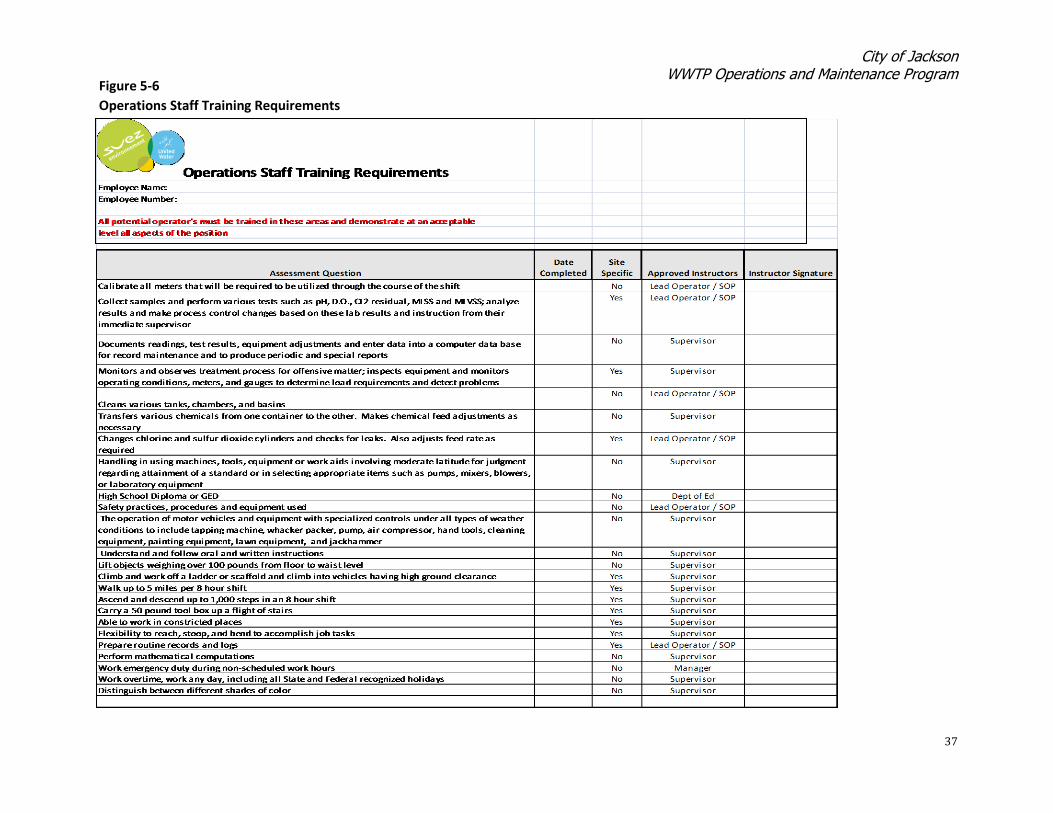
O&M Staff Training
All UWS-MS O&M staff receives initial (upon hire) and periodic refresher training on a
variety of activities, knowledge, and skills required for them to perform their jobs
successfully and safely. An excerpt of the UWS-MS operations staff training requirements is
shown on Figure 5-6. An example of maintenance staff training requirements is shown on
Figure 5-7.
Special Skills/Abilities Needed:
Familiarity and adherence to all environmental and safety compliance regulations.
Proficient knowledge of MicroSoft Office including Excel, Word, and Outlook.
Able to work independently and prioritize work activities.
Able to read and understand blueprints (mechanical, structural and electrical.) Knowledge of both power and control circuits and able to read electrical wiring and ladder
schematics.
Ability to understand and execute written and/or verbal work orders and assignments.
Ability to perform math and algebra calculations with the use of a calculator.
Ability to adjust chemical feeds and processing equipment to maintain compliance.
Knowledge of and ability to perform standard laboratory sampling testing and maintain collection
records. Familiarity with or ability to learn and utilize computerized maintenance management system.
Nature & Scope-Principal Areas of Responsibilities:
Performs, with minimal supervision:
Actions are controlled by the Plan of Operation and SOPs. Work is reviewed on a spot
check basis by a supervisor/manager who is generally available.
A variety of operational and maintenance tasks relevant to maintain safe and reliable
operations of water and/or wastewater treatment facilities and/or collection storm water
systems ensuring operational compliance with state and federal regulations.
Basic knowledge or normal and abnormal process and equipment conditions and capable
of taking appropriate, safe actions or reporting conditions to supervisor/manager.
Update and modify SOPs for review and approval of supervisor/manager prior to
implementation.
Routine cleaning and general housekeeping duties in work and plant reas as needed,
including but not limited to sweeping, dusting, mopping, painting, cleaning of weirs, belt
presses and other process equipment and areas.
Performs preventive, predictive and corrective maintenance following LOTO procedures
and installs, inspects and repairs process equipment.
Lubricates, adjusts and maintains shop, field and plant equipment, including inspection,
cleaning, repairing and troubleshooting of pumps, motors, valves, compressors, pipelines,
wet wells and various other process equipment.
Trains and/or assists in the training of new or less experienced team members.
Must comply with and may monitor the team and/or facility for compliance with safety
and environmental regulations.
Other duties as needed and assigned.
City of Jackson WWTP Operations and Maintenance Program
37
Figure 5-6
Operations Staff Training Requirements

City of Jackson WWTP Operations and Maintenance Program
38

City of Jackson WWTP Operations and Maintenance Program
39
5.3 WWTP PM Program This section describes the preventative maintenance programs for treatment plant systems
and equipment. The PM program consists of periodic inspection of all equipment containing
electrical, mechanical, and physical components.
Guidance to Managers and Field Personnel
UWS-MS provides appropriate guidance to managers and field personnel for scheduling and
performing preventative maintenance activities on wastewater treatment plant equipment.
This guidance includes detailed PM tracking using the eRPortal CMMS to insure that all
scheduled PM activities are routinely completed. The guidance consists of:
Identification of all systems and equipment where PM is required.
Identification of critical equipment required to maintain treatment operations.
Itemization of required PM tasks for each item of equipment.
Instruction in equipment, tools, and materials required to complete PM work.
Training necessary to complete PM activities.
Instruction on documentation to update the eRPortal CMMS used to track PM history.
Preventative Maintenance Practices
Preventative Maintenance is performed on all plant equipment where it is identified as
being required, either critical or non-critical. Procedures for identification and tracking of
critical equipment were described in Section 3. UWS-MS maintains a library of equipment
O&M Manuals furnished by the various manufacturers of the equipment. The
manufacturer’s O&M instructions are followed in scheduling and performing maintenance
tasks, including preventative maintenance. Maintenance staff are instructed in the skills,
tools, and procedures necessary to perform the preventative maintenance activities. The
training also covers procedures for recognizing various indicators that the equipment is
experiencing other problems, and that corrective maintenance is required.
Preventative Maintenance Scheduling
Preventative maintenance activities are scheduled in the eRPortal CMMS as defined by the
UWS-MS Maintenance Manager and Maintenance Planner. An example PM schedule is
shown on Figure 5-8.
Preventative Maintenance Work Orders
All maintenance work orders are generated and tracked using the eRPortal CMMS. A screen
shot of the eRPortal maintenance home screen is shown on Figure 5-9. Instructions to staff
on how to create and close a work order are listed on Table 5-1.

City of Jackson WWTP Operations and Maintenance Program
40
Figure 5-8
Example PM Schedule
PM# DueDat
e
Craft
365 Days 2.00
30 Days 0.20
365 Days 1.00
Preventative Maintenance Summary by AssetReport Filters: DivisionID = LS
Est
HoursFrequency WOType PMNotes
Asset: LS01-AMANDA-LANE - LIFT STATION Department: LS01 - Amanda Lane
2069 12/28/2013 M - Maintenance 2 - PM Lift Station Pump Inspection - Annual
2086 07/03/2013 M - Maintenance 2 - PM Lift Station Inspection (South) - Monthly
Asset Total: 2.20
Asset: LS01-CNTR-PANEL - CONTROL PANEL Department: LS01 - Amanda Lane
2080 02/01/2014 M - Maintenance 2 - PM Thermography Inspection Lift Stations- Annual
Asset Total: 1.00
eRPortal CMMS PM Scheduler

City of Jackson WWTP Operations and Maintenance Program
41
Figure 5-9
Jackson eRPortal Computerized Maintenance Management System
Work Order Generation and Tracking

City of Jackson WWTP Operations and Maintenance Program
42

City of Jackson WWTP Operations and Maintenance Program
43
5.4 Predictive Maintenance In addition to normal PM, UWS-MS also proactively performs certain Predictive
Maintenance activities. Predictive Maintenance is a process used to identify degree of wear
and useful life remaining of equipment components and parts that otherwise show no
outward sign of failure. An example is the annual thermographic inspection of control
panels and motors as shown on Figure 5-10. Thermographic inspection involves infrared
scanning of electrical control panels and motors, as well as other components such as
equipment bearings, to detect heat buildup. If a hot spot is identified and determined to be
excessive, more detailed investigation will be performed and required corrective
maintenance will be scheduled.
5.5 Corrective Maintenance A good preventative maintenance program will minimize equipment malfunctions that
result in the need for unscheduled repairs, referred to as corrective maintenance1. While
UWS-MS has aggressive Preventative Maintenance and Predictive Maintenance programs in
place, corrective maintenance actions are periodically required to perform needed repairs
on equipment and systems. Procedures used by the City of Jackson to perform corrective
maintenance, when it is needed, are described below.
Repair or Replace Decision
For each major item of equipment requiring repair, a decision is first made whether to
perform the repair or replace the item with new equipment. UWS-MS has developed a
standard procedure that is used in evaluating whether to repair or replace the equipment.
The UWS-MS decision criteria used are:
Utilize eRPortal CMMS to review equipment maintenance history.
Consider age, number of failures, maintenance labor hours expended, and past costs
associated with equipment repairs.
Consider availability and lead time for replacement parts.
If size is less than 5 HP, the motor should be replaced.
If above guidelines suggest that repair may be a good option then request quotes for
repair as well as replacement.
If repair cost is more than 50% of the replacement cost, estimate the years of useful life
for the repair and replace options. Determine the annual cost for each option using the
available quotes and select the lowest annual cost option.
If repair cost is less than 50% of the replacement cost, proceed with repair.
1 ‘Reactive maintenance’ is the term used in the Consent Decree.

City of Jackson WWTP Operations and Maintenance Program
44
Figure 5-10
Predictive Maintenance Example
Thermographic Inspection of Electrical Components
Control Panel Thermography Inspection Results

City of Jackson WWTP Operations and Maintenance Program
45
Work Order Procedures
When corrective maintenance needs are identified, a Work Order is entered into the
eRPortal CMMS by the O&M staff. Execution of the Work Order then follows the procedure
outlined on Figure 5-11. Scheduling and tracking of Corrective Maintenance Work Orders is
performed through the UWS-MS eRPortal CMMS as described above.
For all Work Orders, whether they be preventative, predictive, or corrective, Purchase
Orders to UWS-MS registered vendors for outside repair services required, parts not in
inventory, or other outside purchases needed to complete the corrective maintenance
actions are generated using eRPortal CMMS as described in Section 3.
Maintenance Tracking System
Wastewater treatment plant equipment inspection and maintenance activities are
documented using the eRPortal CMMS work order system as described in Section 3. The
CMMS is used for maintenance tracking and record keeping. As equipment maintenance
activities are completed by the O&M crews, the results are entered into eRPortal and a work
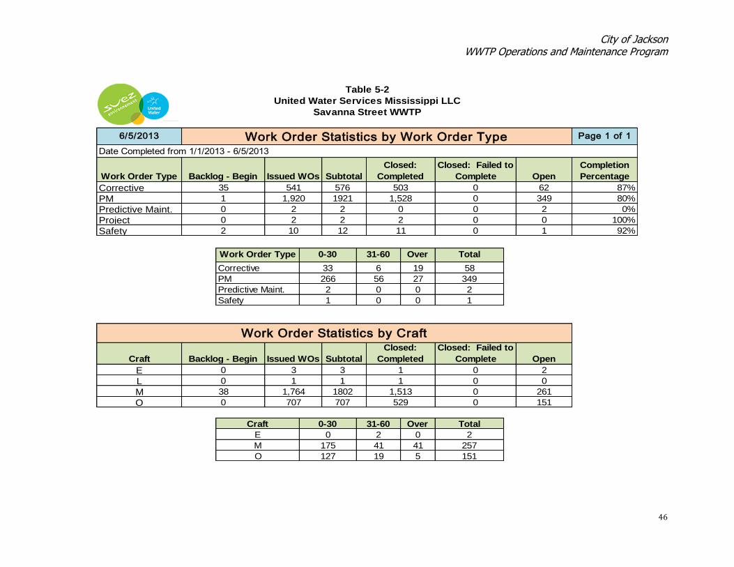
order completion log is generated. Statistics are also kept on work order history. Work
order completion status reports are generated by the O&M staff using the UWS-MS eRPortal
CMMS as needed. The reports can be easily produced using any date range required, such as
prior year, year-to-date, monthly, or any other parameters, depending on the purpose of the
report. Maintenance reports are generated as directed by the Plant Manager, Maintenance
Manager, or other O&M staff member as requested or necessary. An example of the Work
Order Statistics report is shown on Table 5-2.
Figure 5-11
Corrective Maintenance Work Flow
City of Jackson WWTP Operations and Maintenance Program
46
87%
80%
0%
100%
92%
Work Order Statistics by Work Order Type Page 1 of 1
Table 5-2
United Water Services Mississippi LLC
Savanna Street WWTP
6/5/2013
Date Completed from 1/1/2013 - 6/5/2013
Backlog - Begin Issued WOs Subtotal
Closed:
Completed
Closed: Failed to
Complete Open
Completion
PercentageWork Order Type
0 349
Corrective 35 541 576 503 0
2 2 0 0
62
PM 1 1,920 1921 1,528
2
Project 0 2 2 2 0 0
Predictive Maint. 0
Safety 2 10 12 11 0 1
Work Order Type 0-30 31-60 Over
60
Total
Corrective 33 6 19 58
PM 266 56 27 349
Predictive Maint. 2 0 0 2
Safety 1 0 0 1
2
L 0 1 1 1
261
Work Order Statistics by Craft
Craft Backlog - Begin Issued WOs Subtotal
Closed:
Completed
Closed: Failed to
Complete Open
0 0
E 0 3 3 1 0
O 0 707 707 529 0 151
M 38 1,764 1802 1,513 0
Craft 0-30 31-60 Over Total
E 0 2 0 2
M 175 41 41 257
O 127 19 5 151

City of Jackson WWTP Operations and Maintenance Program
47
5.6 Emergency Maintenance Procedures are in place by UWS-MS to ensure that failures of equipment or loss of power
during emergency situations are corrected in a timely fashion. These procedures were
developed to limit the downtime of the equipment or facility during the abnormal
conditions. Examples are the Wastewater Treatment Plant Power Failure SOP and the
Control Panel Damage SOP included in Appendix B.
5.7 Operation and Maintenance Program Summary The City of Jackson currently has in place a sophisticated maintenance program for its
wastewater treatment plants implemented by its professional contract operator, UWS-MS. A
state of the art computerized maintenance management system, eRPortal, is used to
schedule maintenance activities, generate work orders, and track maintenance completed.
UWS-MS has a fully qualified and trained staff assigned to perform maintenance functions.
Including the WWTP O&M standard operating procedures described in this report, the
current City of Jackson WWTP O&M program is compliant with the requirements listed in
the Consent Decree. Consequently, no further implementation measures or additional
changes to the current program appear to be necessary.


Appendix A
Savanna Street WWTP Sludge Management Plan


A-1
City of Jackson, Mississippi
Sludge Management Plan
Introduction The City of Jackson Savanna Street WWTP is a 46.0 MGD activated sludge plant with storm water holding lagoons. The plant stabilizes waste activated sludge by means of aerobic digestion. The digestion process produces thickened, liquid, stabilized organic bio-solids at a concentration of about 2% and dewatered of about 20%. The bio-solids meet the requirements established by Mississippi Department of Environmental Quality (MDEQ) and the US EPA for Land Application. Sludge from the City’s Trahon/Big Creek WWTP and Presidential Hills WWTP is hauled to the Savanna Street plant for processing. The Trahon/Big Creek WWTP is a 4.5 MGD oxidation ditch activated sludge plant. The wasted sludge from this facility is thickened in an aerobic digester prior to hauling. The Presidential Hills WWTP is a 0.75 MGD aerated lagoon activated sludge plant. It is being replaced by a sequencing batch reactor activated sludge plant that will start up in mid-2014. Sludge from the new plant will be conveyed to the Savanna Street plant. The sludge de-watering operation utilizes the following basins and equipment to achieve Class B sludge: gravity thickener, two aerobic digesters, 3-2 meter belt filter presses (avg. 70 gals/min sludge feed rate), 1 centrifuge (avg. 250 gals/min sludge feed rate), and 1-2.2 meter belt filter press (avg. 450 gals/min sludge feed rate). Liquid polymer is used on all de-watering machines to achieve coagulation. The selected method of sludge disposal is by surface land application at agronomic rates. All application sites are permitted for sludge application and all but one are privately owned by local farmers. The Management Plan is found below. This will include loading rates based on expected sludge quality and quantity, the crop selected by the land owner and limiting constituent for application. The anticipated limiting constituent is nitrogen. The plan will also include the application method, harvest requirements, monitoring, pollutant tracking and monitoring. When land application is not possible due to wet weather conditions, etc., de-watered sludge will be disposed of at the local landfill currently being operated by BFI. The management plan is in compliance with the State and Federal reporting guidelines pertinent to 40 CFR 503 regulations, as well as on the findings of specific investigations, historical operational data and input from various United Water associates experienced in the land application of bio-solids. The management plan is applicable of bio-solids and those that are to be permitted in the future.

A-2
Management Plan The dewatered sludge outlined in this program shall follow these buffer zone requirements:
Property Line Waters of the State
Wells, Public/Private
Exterior Roadways
Dwellings
De-watered 200 ft. 200 ft. 500/250ft. 200 ft. 300 ft.
All soil pH levels will be monitored and adjusted accordingly by applying Lime
Dewatered application of bio-solids will be applied to slopes of 6 to 12%.
Bio-solids will be applied according to agronomic loading rates for each crop it is applied upon.
Bio-solids will not be applied to flooded, frozen, or snow covered ground.
Bio-solids will not be applied to land that adversely affect threatened or endangered species.
No annual pollutant loading rate shall be exceeded.
Signs will be posted that restrict access to the application sites.
Bio-solids will not be stockpiled at the site unless in an enclosed tank or building for a period not to exceed 30 days.
No grazing shall be allowed on the site for 30 days after bio-solids application.
Public access to the site shall be restricted for 30 days when there is low potential for public exposure and one year when there is high potential for public exposure.
Application Sites This program currently includes 12 sites. They are labeled as follows:
Byram Landfill Permitted for 560 acres
Kainz Property Permitted for 137.3 acres
Varnado Property Permitted for 34.7 acres
Mason Property Permitted for 75.1 acres
Murphy Davis Property Permitted for 298.8 acres
Holmes Property Permitted for 261.8 acres
Fisher Property (Site #1) Permitted for 150 acres
Fisher Property (Site #2) Permitted for 109 acres
Berry Property Permitted for 223.8 acres
Darden Property (Site #1) Permitted for 624 acres
Darden Property (Site #2) Permitted for 32 acres
Sullivan Property Permitted for 208.4 acres

A-3
Sludge Quality The main constituents of concern are nitrogen (including ammonia, total kjeldahl nitrogen, nitrates, and nitrites). Values for nitrogen were obtained from the previous years. Below are the sludge metal results annualized for the 2012 calendar year. All of the laboratory results below can be found on the laboratory’s letterhead and the specific analytical method (also contained in annual 40 CFR 503 Report)
Dewatered Sludge
Metals Ceiling Limits 2012
mg/kg Results
Arsenic 75 9.65
Cadmium 85 1.1
Chromium 3000 18.4
Copper 4300 186
Lead 840 17.4
Mercury 57 0.4
Molybdenum 75 9.7
Nickel 420 18.1
Selenium 100 15.1
Zinc 7500 290.8

A-4
Sludge Loading Rates
Nutrient Uptake Rate for Crops lbs. / acre – year
(table 4-11, EPA Process Design Manual – Land Treatment of Municipal Wastewater)
Nitrogen Phosphorus Potassium Forage crops:
Coastal Bermuda grass
356 – 600 31 – 40 201
Ryegrass 178 – 250 54 – 76 241 – 290
Tall fescue 134 - 290 27 268
Field crops:
Corn 156 – 178 18 - 27 98
Cotton 67 – 98 13 36
Soybeans* 222 9 – 18 27 – 49
Wheat 143 13 18 - 40
* Legumes will also take nitrogen from the atmosphere. Land application will be based on the EPA schedule 40 503 regulations that state the agronomic loading rate of plant available nitrogen for the selected crop will be met. The table below, current permitted fields, are planted in Coastal Bermuda grass. Bermuda grass has an uptake rate of 300 to 600 lbs. of plant available nitrogen per acre per year. The average total nitrogen is 7.8 percent of the organic sludge. We have selected 400 lbs. per acre as our maximum loading rate. Crop harvest will remove the nitrogen from the fields. Nitrogen will be mineralized over a 10 year period as regulated by the bio-solids requirements found in 391-3-6-.17. Ultimately, 56% of the total kjeldahl nitrogen is plant available over the 10 year period. The nitrates, nitrites, and ammonia are immediately plant available in the first year. The only part that would not be plant available would be lost through de-nitrification and volatilization. The following table lists the percentage of mineralization:
Mineralization Table for bio-solids
Year 1 30%
Year 2 15%
Year 3 8%
Year 4 4%
Year 5 3%
Year 6 3%
Year 7 3%
Year 8 3%
Year 9 3%
Year 10 3%
We will use HACH WIMS and MS Excel to track and mineralize the nitrogen and all other constituents applied, including dry tons per acre. The programs are set up to track nitrogen for any crop that is planted and the corresponding nitrogen needs for that crop. They will also track all priority pollutants and forecasts the longevity of the sites.

A-5
Land Application Operations The bio-solid application system has as its primary objective provision of adequate treatment of the WWTP sludge through the crop/soil system. A secondary goal is to maximize agricultural production. Operations are developed that remain consistent with these objectives. An essential element of land application is a manager that can direct and oversee day to day operations. This person will schedule applications that will coincide with the harvest schedule of the land owner, and track the applications. Site records will be kept at the wastewater treatment plant for the duration of the application and the 10 years beyond. Monitoring records will be kept of the sludge results, soil sample results and crop analyses as well as harvest records. Operational records that will be kept in the HACH WIMS computer program include:
Dates of application
Fields applied upon
Volume of sludge applied
Corresponding nitrogen and metal loadings
Cumulative nitrogen (Excel) and metal loadings
Annual dry tons applied per acre
All sludge and soil lab analyses
Lime applications in lbs./acre Results for all monitoring and application activities will be submitted in the Annual Sludge Report submitted to EPD by January 31 of each year to contain pollutant concentrations, required certification statements, pathogen and vector attraction reduction requirement documentations, annual bio-solids application rate, site locations, acreages, and quantity applied to each site. In addition, the Annual Sludge Report will be submitted to the EPA by February 19 of each year. The bio-solids will be slung via a tractor and pull behind ag-slinger soon after each hay crop is harvested. The 30 day waiting period before the next harvest will be honored by the land owner. The schedule for application will be decided through communication between the landowner and land application manager. Sludge will not be applied during periods of rain. The privately owned Little Dixie Landfill operated by BFI will be used at that time by dewatering the bio-solids and disposing of them in the landfill. The soil will be sampled at least annually and more as necessary to bring the soil pH to the desired level. PSRP PSRP will be met by following Alternative 1 in the schedule 40 CFR 503 regulations. This will be 6 fecal coliform samples using the geometric mean less than 2 million CFU per gram of bio-solids on a dry weight basis.

A-6
Vector Attraction Reduction VSR will be met by following Option 10 in the schedule 40 CFR 503 regulations by the following method. Bio-solids will be incorporated into the soil within 6 hours of application to or placement on the land. Incorporation will be accomplished by plowing or some other means of mixing the bio-solids into the soil. Bio-solids Application Bio-solids will be loaded at the sludge loading station as a dewatered material at approximately 20% into the semi-dump trailer. The bio-solids will then be transported to the site where it will be surface spread and slung via a tractor and pull behind ag-slinger. The primary choice of bio-solid land application will be conducted utilizing a tractor and ag-slinger. The first step in this process will be to de-water the bio-solids from an estimated 2% solids from the solids holding tank to an estimated 20% solids utilizing belt filter presses and centrifuge located at the wastewater facility. The bio-solids will be loaded into a semi truck and trailer utilizing a front end loader and conveyor belt system extending from the belt filter presses. When the trailer has been filled with de-watered sludge, estimated to be between 18 and 20 tons, the trailer will be hauled to the pre-determined application site for that particular day. We will then dump the sludge on the designated dump site. A frond end loader will pick up the sludge from the dump site and empty its bucket into the ag-slinger. The tractor will then proceed into the field and after reaching the field start site, the tractor operator will engage the ag-slinger as to begin spreading the sludge in the crop row direction. The ag-slinger will spread the sludge on both sides of the machine approximately 60 feet outward. After the crop has been completely land applied to, or the daily allotted volume of sludge has been utilized and the only remnants of product to remain in the dump site is small pieces and insignificant volumes to begin another spread cycle, the dump area will be thoroughly cleaned by the front end loader and utilization of hand tools such as rakes and shovels if necessary. The tractor, ag-spreader, and dump site will be cleaned on a daily basis. At no time will equipment show visible signs of sludge or recent activities of spreading. When it becomes necessary to move the equipment from one application site to another, not only will the before mentioned equipment be thoroughly cleaned, but all transport equipment will be inspected and cleaned as well. During periods of adverse weather conditions, or times that would not be advantageous to the land owners for land application, all bio-solids will be de-watered as previously explained and the sludge will be transported and disposed of in the Little Dixie Landfill. All sludge disposed of via land application will be tracked and monitored for quality pertaining to the applicable current state and federal regulations as well as land applied volume measured in tonnage. As well, all sludge disposed of via land fill will be tracked and monitored for quality pertaining to the applicable current state and federal regulations as well as land filled volume measured in tonnage.

A-7
Sludge Monitoring Plan
Nutrients and Metals The nutrient and metals analyses will be performed on an every other month basis in accordance with the annual dry tons. Representative samples will be collected to demonstrate compliance. Vector Attraction Reduction VSR will be met by following Option 10 in the schedule 40 CFR 503 regulations by the following method. Bio-solids will be incorporated into the soil within 6 hours of application to or placement on the land. Incorporation will be accomplished by plowing or some other means of mixing the bio-solids into the soil. Pathogen Reduction PSRP will be met by following Alternative 1 in the schedule 40 CFR 503 regulations. This will be 6 fecal coliform samples using the geometric mean less than 2 million CFU per gram of bio-solids on a dry weight basis. Enough samples will be analyzed to truly represent pathogen reduction.


Appendix B
Wastewater Treatment Plant Standard Operating Procedures
1. Belt Filter Press
2. Dewatering Centrifuge
3. Wet Weather Operating Plan
4. Plant Power Failure
5. Control Panel Damage


B-1
BELT FILTER PRESS # 1
STANDARD OPERATING PROCEDURE
JACKSON, MS - SAVANNA STREET WWTP
Original Release Date: 28 April 2011
Revision Date: 28 April 2011
Authorization: _____________________________
Reference Document(s): _____________________
Purpose:
The purpose of the Belt Filter Press (BFP) is to remove water from the treated sludge to reduce hauling costs and
produce sludge with the highest possible total solids concentration.
General Description:
The dewatering operation consists of three (3) – 2.2 meter Ashbrook-Simon-Hartley belt filter presses and one (1)
portable press. Polymer is supplied to the presses with one Polymaster unit and two Polyblend units. Filtrate from the
presses is returned to the head works of the treatment plant and cake is transferred to the holding area by means of
conveyer belts for eventual land application.
Safety:
1. Always wear proper personnel protective equipment including safety glasses, safety toed shoes and clothing.
Table 1 - Associated Equipment
Equipment Equipment Number
Polymer units CF 11601
Conveyor belts CR 11601, 02
Loader N/A
Frac Tank TK 11601
Sludge Pumps PP11601

B-2
Startup
Action Location/Picture
OPEN Frac tank discharge valve.
OPEN sludge pump # 1 suction valve.
OPEN sludge pump # 1 discharge valve.
INSURE isolation valve is CLOSED.
Photo 1 – Frac tank discharge valve for sludge pump
# 1 & 2
Photo 2 – Sludge pump # 1 suction valve
Photo 3 – Sludge pump # 1 discharge valve
Photo 4 – Sludge pump # 1 isolation valve

B-3
Startup
Action Location/Picture
CHECK belts for debris.
CHECK belt alignment.
INSURE ploughs are in the DOWN position.
INSURE tension valve is in the retract position.
CHECK hydraulic oil level.
OPEN the two (2) inch wash water supply valve located
beside each press.
Photo 5 – Ploughs
Photo 6 – Tension/retract switch
Photo 7 – Hydraulic oil sight gauge
Photo 8 – Wash water supply valve

B-4
Startup
Action Location/Picture
TURN the belt tension/retract valve to the tension position.
TURN main breaker at the Sludge Conveyor Control Box to
the ON position to activate the cross conveyor.
TURN conveyor switch to the Hand position.
TURN ON discharge conveyor by placing the switch in the
ON position.
Photo 9 – Tension position
Photo 10 – Sludge conveyor control box
Photo 11 – Discharge conveyor switch
Photo 12

B-5
Startup
Action Location/Picture
At the Control panel:
INSURE power is to the BFP control panel # 1 by checking
that the control power switch is in the ON position.
PRESS the green start button for the primary power on the
BFP control panel. The green light should illuminate.
PRESS the green start button for the following equipment in
the sequence listed below. The green light should illuminate for
each item.
Hydraulic pump
Booster pump
Belt tension
INSURE hydraulic tension circuit pressure is 300 to 400psi.
At the Control panel:
PRESS the green start button for the following equipment in
the sequence listed below. The green light should illuminate for
each item (See Photo 12).
Belt drive
Sludge grinder
Polymer system
Sludge pump
Photo 12 – BFP # 1 control panel
Photo 13 – Hydraulic pressure gage

B-6
Startup
Action Location/Picture
At the Polymer Unit:
OPEN quarter turn water supply valve.
TURN the toggle switch ON to energize the potable water
solenoid.
TURN toggle switch to energize polymer mixing chamber.
Photo 14 – Quarter water supply valves
Photo 15 - Potable water toggle
Photo 16 – Polymer mixing chamber toggle

B-7
Startup
Action Location/Picture
ADJUST quarter turn water valve to deliver 20 psi to mixer.
TURN toggle switch on LMI pump to internal position.
At the Variable Frequency Drive (VFD):
PRESS the start button for BFP # 1.The press should be
fully operational.
Photo 17 - Quarter turn water valves
Photo 18 - LMI toggle switch
Photo 19 - VFD # 1 Start button

B-8
Normal Operation
Action Location/Picture
CHECK press sludge feed area to INSURE full belt width
distribution and coagulation.
CHECK sludge feed area for evidence of small bubble white
foam indicating excessive polymer feed.
CHECK for proper furrow of sludge through ploughs.
CHECK perforated roller section for full width sludge
distribution.
CHECK drain sections for sludge buildup: hose down if
necessary.
OPEN and CLOSE flushing valve on upper spray boxes as
required to clean belts.
Photo 20 – Sludge feed area
Photo 21 – Sludge furrows
Photo 22– Perforated roller
Photo 23 – Upper spray box flushing valve

B-9
Normal Operation
Action Location/Picture
OPEN and CLOSE flushing valve on lower spray boxes as
required to clean belts.
CLEAN belts with bleach, vinegar, and water at least twice per
shift.
CHECK all pressure gauges to INSURE normal operating
ranges.
OPTIMIZE belt speed, sludge and polymer feed to maximize
sludge flow and minimize polymer use.
INSURE tracking paddles are in correct position and belt is not
drifting.
CHECK Frac tank for sludge condition and volume.
Photo 24 – Lower spray box flushing valve
Photo 25 – Tracking paddle

B-10
Shutdown
Action Location/Picture
At the VFD:
PRESS red stop button to TURN OFF the sludge pump.
At the Polymer units:
TURN OFF toggle switches on polymer mixer and LMI pump
(See photo 16 & 18).
At the Control panel:
PRESS the Red stop buttons sequentially for the following
equipment:
Sludge pump
Polymer system
Sludge grinder
ALLOW presses to discharge all sludge on belts.
RUN presses for fifteen (15) minutes to allow complete
cleaning of belts.
PRESS the red Stop buttons sequentially for the following
equipment:
Belt drive
Belt tension
Booster pump
Hydraulic pump
TURN the tension/retract valve to retract (See photo 6).
CLOSE the two inch water supply valve (See photo 8).
TURN OFF the control power switch at the control panel.
DISENGAGE the main breaker at the control panel.
If All Presses are shut down:
TURN OFF main breaker at the sludge conveyor control box to
deactivate cross conveyor.
TURN OFF toggle switch for the discharge conveyor.
Photo 26 – Control panel
Photo 27 – Control panel red stop buttons

B-11
Emergency Shutdown
Action Location/Picture
PULL the red emergency stop cable surrounding each press.
PRESS the red emergency stop button each BFP control panel.
PULL the red emergency stop cable below the cross conveyor
for complete shutdown of all presses and associated equipment.
Photo 28 – Press emergency stop cable
Photo 29 – Control panel emergency stop button
Photo 30 – Cross conveyor emergency stop cable

B-12
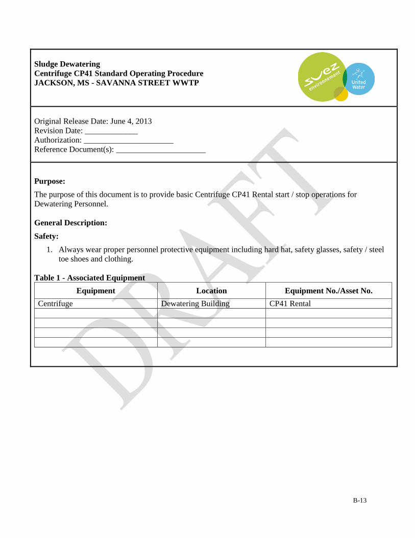
B-13
Sludge Dewatering
Centrifuge CP41 Standard Operating Procedure
JACKSON, MS - SAVANNA STREET WWTP
Original Release Date: June 4, 2013
Revision Date: _____________
Authorization: ______________________
Reference Document(s): ______________________
Purpose:
The purpose of this document is to provide basic Centrifuge CP41 Rental start / stop operations for
Dewatering Personnel.
General Description:
Safety:
1. Always wear proper personnel protective equipment including hard hat, safety glasses, safety / steel
toe shoes and clothing.
Table 1 - Associated Equipment
Equipment Location Equipment No./Asset No.
Centrifuge Dewatering Building CP41 Rental

B-14
Startup
Action Location/Picture
On the MAIN SCREEN touch the System Overview icon
in lower right hand corner of the control panel screen.
On the SYSTEM OVERVIEW screen touch the
Centrifuge Sequence Control icon.
From the CENTRIFUGE SEQUENCE SELECT menu,
select Auto Start Sequence icon.

B-15
Startup
Action Location/Picture
On the AUTO STOP SEQUENCE screen touch the Auto
Start Initiate icon and the System Ready for Startup,
Startup Active and Hydraulic Pump lights will illuminate
and turn green for the first segment of system startup.
The Centrifuge Running, Centrifuge At-Speed, Feed
System and System Operating lights will automatically
illuminate and turn green for final system startup.
Once all six lights are green and illuminated, the
Centrifuge will automatically start.

B-16
Normal Operation
Action Location/Picture
Centrifuge is in full operation.

B-17
Shutdown
Action Location/Picture
On the SYSTEM OVERVIEW screen touch the
Centrifuge Sequence Control icon
From the CENTRIFUGE SEQUENCE SELECT menu,
select Auto Stop Sequence

B-18
Emergency Shutdown
Action Location/Picture
On the Panel depress red Emergency Stop button to stop
all operations and systems.

Jackson MS Savanna Street Wastewater Treatment Facility
Standard Operating Procedure
Treatment Works Bypass Minimization and Wet Weather Operating Plan
Release Date: May 2014
Authorization: _David Lewis_

Jackson MS Savanna Street Wastewater Treatment Facility
Treatment Works Bypass Minimization and Wet Weather Operating
Plan
Standard Operating Procedures
May 2014
Table of Contents
INTRODUCTION ………………………………………………………………………………………………. 1
DISCLAIMER ………………………………………………………………………………………………. 1
PROCESS OBJECTIVE ………………………………………………………………………………………. 1
PROCESS PERFORMANCE GOALS ………………………………………………………………………. 2
PROCESS PERFORMANCE INDICATORS ………………………………………………………………. 2
DIVERSION / BYPASS LOCATIONS ………………………………………………………………………. 2
TREATMENT LEVEL PRIORITY ………………………………………………………………………………. 3
PROCEDURES FOR BYPASS AVOIDANCE/MINIMIZATION ………………………………………………. 4
BYPASS PREPAREDNESS ………………………………………………………………………………………. 11
NOTIFICATION RESPONSIBILITIES ………………………………………………………………………. 13

Jackson MS Savanna Street Wastewater Treatment Facility
Treatment Works Bypass Minimization and Wet Weather Operating
Plan
Standard Operating Procedures
May 2014
1 of 15
INTRODUCTION
Overall plant operating strategy is to process all flow received up to the permitted limits or capacity limits of the unit processes.
However, equipment failures, collection system Inflow and Infiltration (I&I) or extreme operating conditions may limit the ability to
process all flows coming to the treatment plant. These guidelines and instructions support minimizing the occurrence of treatment
works bypass events and mitigating impacts should bypass be unavoidable. A discussion of the causes and guidelines for reducing
overflows of raw sewage are presented in the Standard Operating Procedure (SOP).
A bypass of any part of the treatment system is a significant incident and should be managed in accordance with United Water (UW)
policy. A bypass may be elevated to major incident designation if the discharge occurs during dry weather or is of a magnitude great
enough to cause upstream manhole surcharge and is also in direct violation of the existing EPA Consent Decree. Specific notification
responsibilities will be addressed in a later section.
DISCLAIMER:
This document was prepared in expectation of the storm cell lagoons being completely empty of water and free of excess solids
content, as well as, all referenced raw influent pumps, and all other plant process equipment and basins, being in proper operating
condition and available for utilization. At the time of this document inception, May 2014, the referenced storm cells have been
dredged and cleaned to a yet to be determined level, and only two 30 mgd raw influent pumps are operational and available for use.
PROCESS OBJECTIVE
In keeping with BEST practices, and to lessen potential adverse effects to the environment and human health, the preference is to treat
combined flows during wet weather events to at least some degree of treatment. Ideally, full treatment up to the wastewater plants
permitted capacity should be accomplished prior to diverting and storing water in the storm cells and bypass channel. This allows for,
at a minimum, dis-infection of bypassed water compared with no treatment when overflows are experienced in the collection system.

Jackson MS Savanna Street Wastewater Treatment Facility
Treatment Works Bypass Minimization and Wet Weather Operating
Plan
Standard Operating Procedures
May 2014
2 of 15
Pump all influent flows entering the facility to proper treatment according to the normal sequence of unit processes
Gradual increases in flow to avoid solids washout from the sedimentation basins
Maximize treatment to all flows entering the facility
Closely monitor, control and limit flows bypassed around treatment units or overflow due to facility capacity limits
Avoid damage to upstream private and public property
Avoid facility damage
Limit possible environmental and health impacts from bypass events
Investigate and evaluate all bypass incidents to ascertain causes and to identify improvements that will help reduce the
frequency and duration of future recurrences
PROCESS PERFORMANCE GOALS
Protect treatment plant from flooding which would impair long term operations
Reducing flow bottle necks
Limit solids washout from the secondary clarifiers which would impair treatment plant long term operations
Temporarily alter operational conditions to maximize flow through available equipment
Maintain positive control of the influent pumping process
Maximize combined storm water treatment during wet weather events by:
1. Capturing the maximum amount of combined storm flow in the storm cell lagoons
2. Bypassing combined storm flow when lagoons are full and collection system flows remain high
3. Providing disinfection to bypasses combined storm flow (This alternative is a better practice than allowing untreated
discharges from manholes and lift stations in the collection system)
4. Recovering stored storm water flow to the treatment plant as plant capacity limits allow and emptying the stored combined
water as soon as practical from the storm cell lagoons and bypass channel
5. Maintain all storm cell lagoons at an empty level to provide maximum available capacity for the next wet weather event

Jackson MS Savanna Street Wastewater Treatment Facility
Treatment Works Bypass Minimization and Wet Weather Operating
Plan
Standard Operating Procedures
May 2014
3 of 15
PROCESS PERFORMANCE INDICATORS
Plants (raw sewage) bypass condition
Flooding of plant areas
Associated equipment shutdown or failure to start when needed
Sewer system surcharge
PLANT BYPASS LOCATIONS
The Savanna Street wastewater treatment facility has the ability to divert wet weather flows into storm holding ponds. When those
ponds reach their capacity, excess flow is then disinfected and discharged with the plant effluent into the receiving stream (Pearl
River).
A manual bar screen allows for flows exceeding the hydraulic capacity of the Headwork’s Bar Screens to be diverted
A bypass exists to allow flow to be diverted around the grit removal system
A bypass exists around the current UV disinfection system. That bypass is currently used at all times and effluent disinfection
is by chlorine
TREATMENT LEVEL PRIORITY
All flows entering the facility should receive treatment according to the normal sequence of unit processes. Equipment failures or
extreme operational conditions, however, may limit the ability to handle all flows. Should it become necessary to bypass portions of
the treatment facilities, there exists a definite order of preference for point of discharge in the treatment process where flows should be
discharged. Treatment level priorities are presented as follows in descending order of preference with the most preferred at the top of
the list and the least preferred at the bottom of the list.
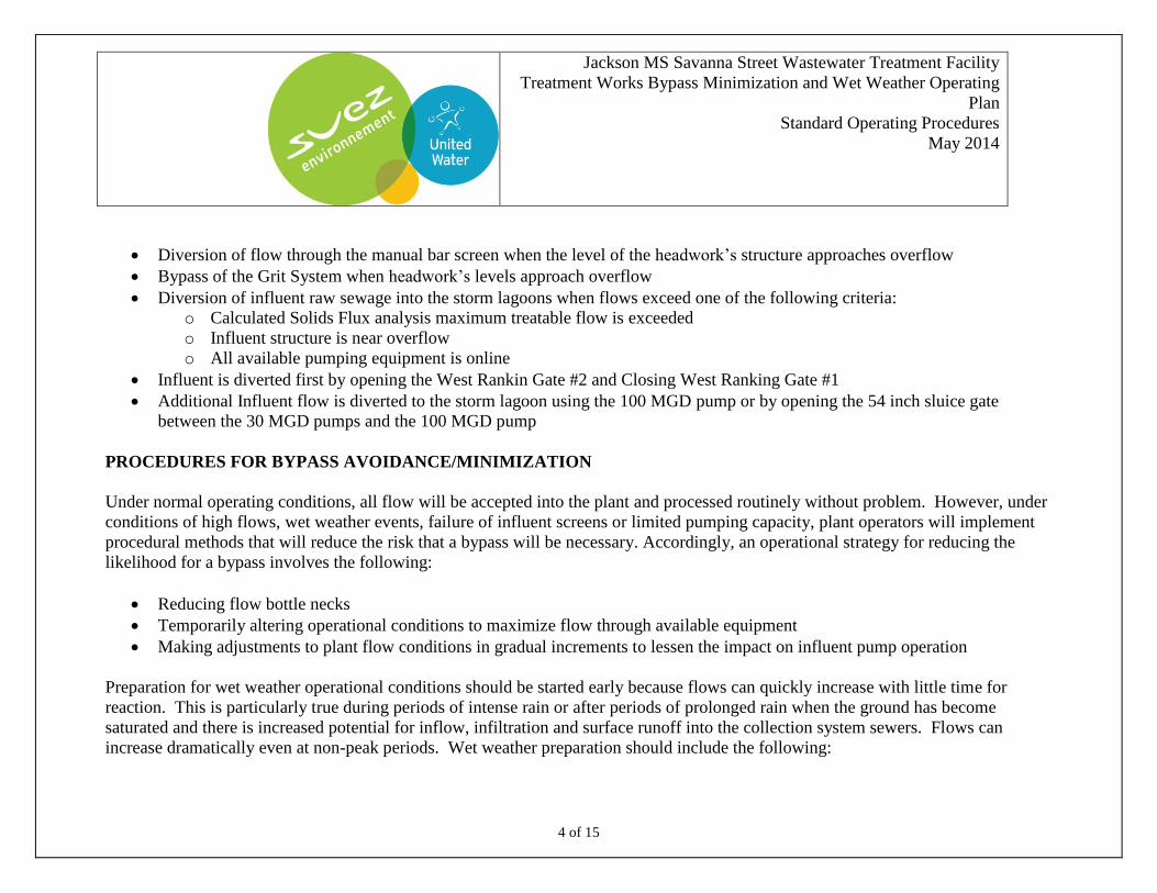
Jackson MS Savanna Street Wastewater Treatment Facility
Treatment Works Bypass Minimization and Wet Weather Operating
Plan
Standard Operating Procedures
May 2014
4 of 15
Diversion of flow through the manual bar screen when the level of the headwork’s structure approaches overflow
Bypass of the Grit System when headwork’s levels approach overflow
Diversion of influent raw sewage into the storm lagoons when flows exceed one of the following criteria:
o Calculated Solids Flux analysis maximum treatable flow is exceeded
o Influent structure is near overflow
o All available pumping equipment is online
Influent is diverted first by opening the West Rankin Gate #2 and Closing West Ranking Gate #1
Additional Influent flow is diverted to the storm lagoon using the 100 MGD pump or by opening the 54 inch sluice gate
between the 30 MGD pumps and the 100 MGD pump
PROCEDURES FOR BYPASS AVOIDANCE/MINIMIZATION
Under normal operating conditions, all flow will be accepted into the plant and processed routinely without problem. However, under
conditions of high flows, wet weather events, failure of influent screens or limited pumping capacity, plant operators will implement
procedural methods that will reduce the risk that a bypass will be necessary. Accordingly, an operational strategy for reducing the
likelihood for a bypass involves the following:
Reducing flow bottle necks
Temporarily altering operational conditions to maximize flow through available equipment
Making adjustments to plant flow conditions in gradual increments to lessen the impact on influent pump operation
Preparation for wet weather operational conditions should be started early because flows can quickly increase with little time for
reaction. This is particularly true during periods of intense rain or after periods of prolonged rain when the ground has become
saturated and there is increased potential for inflow, infiltration and surface runoff into the collection system sewers. Flows can
increase dramatically even at non-peak periods. Wet weather preparation should include the following:

Jackson MS Savanna Street Wastewater Treatment Facility
Treatment Works Bypass Minimization and Wet Weather Operating
Plan
Standard Operating Procedures
May 2014
5 of 15
Anticipate quick need to place the screening equipment on Hand in the event of a rapid flow increase
Placing Grit removal equipment on Hand
When weather forecasts indicate a strong potential for rains, high flow conditions should be anticipated
Defer if possible non-essential maintenance that would require disabling the standby equipment to an alternate time or
schedule the work to be started and completed during the plant low flow period
When inclement weather is forecast, ensure that all emergency generators are operational
Increase frequency of operator rounds to check for obstructions and proper function of all process equipment
The following table illustrates the operating status of most major equipment during normal (non-wet weather) flow periods:
NORMAL OPERATING MODES
North Influent Gate #1 Normally Open 100%
North Influent Gate #2 Normally Closed.
Caney Creek Gate Normally Open
West Rankin Force Main Gate 1 Normally Open – Allows flow from North Rankin to flow to the
influent wet well.
West Rankin Force Main Gate 2 Normally Closed – Allows flow from West Rankin to be diverted
to the storm water lagoon and allows flow from the storm water
lagoon to flow back into the influent wet well.
Raw Sewage Pumps 2 to 3-30 MGD pumps in service depending on flow conditions
100 MGD pump on standby

Jackson MS Savanna Street Wastewater Treatment Facility
Treatment Works Bypass Minimization and Wet Weather Operating
Plan
Standard Operating Procedures
May 2014
6 of 15
NORMAL OPERATING MODES
Storm Flow Gate to the Storm Holding
Ponds Normally Closed
54” Bypass Gate Normally closed
Headwork’s Bar Screens
2 Screens in service in Auto
Operated off of Timers and/or differential level
Influent and Effluent Gates 100 % open
Influent Gate to Bypass Screen open
Headwork’s Structure Both Screen channel effluent gates open
Grit Removal
Both Grit Systems on line in Auto.
Anoxic Zone Both Anoxic Zones in service with influent and effluent gates
100% open. DO controlled at between 0.2 and 0.5 mg/L.
Aeration Tanks All Aeration Tanks in service
Clarifiers
Influent Gates for online Clarifiers set to equalize flows to each
clarifier. Adjustments are made to balance sludge blanket levels.
RAS pumps in Manual with RAS flow set to Minimum as
calculated by solids flux analysis (Due to lack of flow measuring
devices on the RAS system, the pumps are normally run 100%)
WAS pumps in Manual set to waste as calculated to maintain
target MCRT

Jackson MS Savanna Street Wastewater Treatment Facility
Treatment Works Bypass Minimization and Wet Weather Operating
Plan
Standard Operating Procedures
May 2014
7 of 15
NORMAL OPERATING MODES
UV Disinfection UV system is out of service with no plans to repair or return to
service
Chlorine Disinfection / De-
chlorination
Plant Effluent is disinfected using Rotometer #1 and the “Water
Champ” injector located in the clarifier effluent structure.
Chlorine dose is adjusted to achieve a FREE CHLORINE
residual at the process control location of 1.0 mg/L.
A TOTAL CHLORINE residual is taken daily at the final after
de-chlorination for permit compliance
Storm water bypass flow is disinfected using Rotometer #2 and
the inductor in the chlorine feed room.
Storm water bypass disinfection chlorine is adjusted to achieve a
FREE chlorine residual of 1.5 mg/L at the process control sample
point.
Plant effluent is de-chlorinated using a Sulfonator in the head of
the effluent flow channel
Storm water bypass flow is de-chlorinated using a sulfonator in
the head of the diversion flow meter channel
Influent Pumping System Raw Sewage Wet Well
1. The Wet Well levels must be closely monitored and additional raw sewage pumps placed on line to maintain the wet
well level at safe operating depths if the wet well level indicators do not respond to rising wet wells. Additional pumps

Jackson MS Savanna Street Wastewater Treatment Facility
Treatment Works Bypass Minimization and Wet Weather Operating
Plan
Standard Operating Procedures
May 2014
8 of 15
should be placed on line as early as possible to prevent flow surging and washout of solids in the secondary clarifiers.
A fast rising level will require fast response for additional pumping capacity to prevent overflows and flow surges
through the process. During normal dry weather operating days the desired wetwell level is maintained at between 10
and 15 feet. When wet weather has been forecasted the wet well level is controlled at 10 feet. Prior to predicted
rainfall, the polymer feed system located at the secondary clarifier splitter box is placed into service in order to inject
polymer into the RAS system and assist in settling of solids and ultimately allow for additional flow to clarifiers. As
the wet well level increases additional 30 MGD pumps are placed online until one of the following conditions are met:
Calculated Solids Flux analysis maximum treatable flow is exceeded
Headwork’s structure is near overflow
All available pumping equipment is online
2. When one or more of the above criteria has been met and wet well levels continue to rise and reaches a level of 21feet:
Discontinue any Storm Lagoon recovery pumps or flows from the diversion channel gates
Open The West Rankin gate #2 and close West Rankin Gate #1 to allow diversion of the West Rankin flow to
the storm water lagoons
3. If wet well levels continue to rise and flow to the treatment plant has not been maximized:
Continue placing 30 MGD pumps online until all three are online at 100% pumping speed
Discontinue Dewatering process and sludge wasting to minimize in-plant recycle flows and their impact on the
diversion flow. NOTE: Verify with the Operations Manager before discontinuing Dewater and Waste Flows
Discontinue accepting water from leachate and septic tank haulers into the treatment plant
Discontinue leachate pumping from the storm cell bag storage areas
Begin Opening the 54 inch gate to allow diversion of some of the influent flow to the storm lagoon while still
maintaining maximum flow to the treatment plant as defined by the criteria above

Jackson MS Savanna Street Wastewater Treatment Facility
Treatment Works Bypass Minimization and Wet Weather Operating
Plan
Standard Operating Procedures
May 2014
9 of 15
4. If all available 30 MGD pumps are in service at 100% speed and the flow to the treatment plant has been maximized
and the wet well level continues to rise above 23 feet, close the 54 inch gate and use the 100 MGD pump at minimum
speed to allow diversion of flow into the storm lagoons and control the wet well level below 23 feet
5. Once all available pumping equipment is online with maximum flow to the treatment plant and all available diversion
flow to the storm lagoons, restrict the north gate #1 to 5% to allow for storage in the collections system and to keep the
influent wet well below 23 feet. If the wetwell continues to rise, the north gate #1 should be further restricted in 1%
increments until the gate is 100% completely shut. NOTE: Shutting the north gate #1 completely is the final and last
option. However, wetwell levels above 25 feet create a dire circumstance due to danger of flooding the dry pit and
catastrophic failure of motors and controls and should be avoided at all costs.
Location
Task
Steps
Influent Pumping Station 1. Monitor wet well levels and flows a. Monitor wet well level and try to
maintain control at 10 feet during
wet weather.
b. Add additional pumps as required
to maintain the wet well level until
one or more of the following
criteria are met:
o Calculated Solids Flux
analysis maximum treatable
flow is exceeded
o Influent structure is near
overflow
o All available pumping

Jackson MS Savanna Street Wastewater Treatment Facility
Treatment Works Bypass Minimization and Wet Weather Operating
Plan
Standard Operating Procedures
May 2014
10 of 15
Location
Task
Steps
equipment is online.
Headwork’s 2. When flows near or exceeds 60 MGD
notify Operations Manager and place
influent screens and Grit removal
systems in Hand operation
a. Place the Auto/Hand Switches to Hand
6. Secondary Clarifiers
The Secondary Clarifiers ability to process high wet weather flows is largely dependent on the aeration systems ability to
produce a sludge that readily separates and settles rapidly. A model (Solids Flux Analysis) for the Secondary Clarifiers at the
Jackson Mississippi Savanna Street Wastewater Treatment Facility has been developed in order to predict the flow at which
the Secondary Clarifiers will begin to become overloaded and allow washout solids to be carried through the effluent. Prior to
any storm event, check the Daily Exception Report’s Solids Flux analysis sheet for an indication as to how much flow the
Secondary Clarifiers will be able to properly accommodate.
7. Chlorination / De-Chlorination
Place Chlorination / De-chlorination equipment online for the diversion flow once the storm lagoons reach full capacity
and flow begins to exit the storm lagoons and enter the diversion channel. Notify the Lab Supervisor that a diversion is
taking place and follow instructions for collecting the required additional NPDES samples.
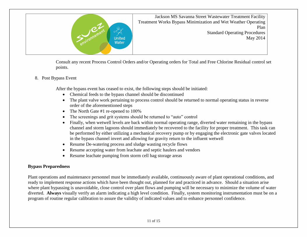
Jackson MS Savanna Street Wastewater Treatment Facility
Treatment Works Bypass Minimization and Wet Weather Operating
Plan
Standard Operating Procedures
May 2014
11 of 15
Consult any recent Process Control Orders and/or Operating orders for Total and Free Chlorine Residual control set
points.
8. Post Bypass Event
After the bypass event has ceased to exist, the following steps should be initiated:
Chemical feeds to the bypass channel should be discontinued
The plant valve work pertaining to process control should be returned to normal operating status in reverse
order of the aforementioned steps
The North Gate #1 re-opened to 100%
The screenings and grit systems should be returned to “auto” control
Finally, when wetwell levels are back within normal operating range, diverted water remaining in the bypass
channel and storm lagoons should immediately be recovered to the facility for proper treatment. This task can
be performed by either utilizing a mechanical recovery pump or by engaging the electronic gate valves located
in the bypass channel invert and allowing for gravity return to the influent wetwell
Resume De-watering process and sludge wasting recycle flows
Resume accepting water from leachate and septic haulers and vendors
Resume leachate pumping from storm cell bag storage areas
Bypass Preparedness
Plant operations and maintenance personnel must be immediately available, continuously aware of plant operational conditions, and
ready to implement response actions which have been thought out, planned for and practiced in advance. Should a situation arise
where plant bypassing is unavoidable, close control over plant flows and pumping will be necessary to minimize the volume of water
diverted. Always visually verify an alarm indicating a high level condition. Finally, system monitoring instrumentation must be on a
program of routine regular calibration to assure the validity of indicated values and to enhance personnel confidence.

Jackson MS Savanna Street Wastewater Treatment Facility
Treatment Works Bypass Minimization and Wet Weather Operating
Plan
Standard Operating Procedures
May 2014
12 of 15
A. O&M Tech Presence:
Plant process equipment is equipped with sensors that monitor critical process conditions. These sensors are set to
trigger various alarms to alert plant personnel of adverse conditions so that corrective actions can be taken. It is still
necessary, however, that plant personnel perform routine inspections of support equipment and systems as a verifying
check on correct performance of field instruments. In addition, routine observation by plant personnel helps to identify
deteriorating trends in performance so that corrective actions can be implemented prior to the development of an alarm
condition that could require immediate and dramatic action to resolve.
Maintain continuous personnel presence in the pumping area or at the SCADA monitor screen to provide for
immediate emergency response.
Close monitoring of the return rate and clarifier performance will provide indications of process integrity as
secondary flows increase.
B. Preparedness Documentation:
Operating conditions are observed every two hours and recorded on the plant log
The O&M Tech will inspect the plant systems and record status in the plant log book
Report equipment deficiencies to the Maintenance Supervisor and/or Maintenance Manager and note in the log
book. Have work requests immediately entered for items requiring other than minor maintenance
C. Routine Instrument Calibration:
Critical instrumentation must be checked regularly and placed on a formal calibration program. This is to
assure accurate representation of field conditions which cannot be easily or directly observed by plant
personnel (currently calibrated at a minimum of annually)
Jackson MS Savanna Street Wastewater Treatment Facility
Treatment Works Bypass Minimization and Wet Weather Operating
Plan
Standard Operating Procedures
May 2014
13 of 15
Notification Responsibilities
According to NPDES permit requirements, verbal notification to MSDEQ must be made within 24 hours of events in which flows are
bypassed around treatment processes. Also, during the Consent Decree period, the Consent Decree manager should be immediately
notified of the condition. In addition, follow up written notification to the MSDEQ within 5 days is also required. Further,
notifications are also required to provide for clear internal communication with UW and The City of Jackson MS. The plant Shift
Operator is responsible for initiating preliminary verbal notifications and making follow up calls to confirm and revise information as
outlined in the UW guidelines.
A. Wet Weather Incident Report:
During high flow events, the O&M Tech will make additional notes as to hourly flows, rainfall amounts and action
items taken during a high flow event. Additionally, items that would require this guideline to be modified in order to
improve the plants ability to process high flows should be noted
B. Contact Lists:
Immediate contact of the Plant Operations Manager as indicated in this UW Notification Policy whenever it becomes
apparent that a Wet Weather incident that may cause an increase in plant flows above 60 MGD. Please see the
emergency contact list for contact numbers. The following list is provided for reference:
Project Manager / Operations Manager – when flows reach 60 MGD
Operations Supervisor so that the UW 800 line and MSDEQ contacts can be made
C. Bypass Incident Investigation and Report (Intelex)

Jackson MS Savanna Street Wastewater Treatment Facility
Treatment Works Bypass Minimization and Wet Weather Operating
Plan
Standard Operating Procedures
May 2014
14 of 15
Each time a plant high flow or bypass event occurs a complete investigation shall be conducted and a written report
prepared. The Shift O&M Tech Lead and Plant Operations Supervisor will conduct an initial investigation and prepare
the preliminary report. For Wet Weather Reports, a report should be filed whenever there is a high flow event where a
diversion into the storm lagoons has occurred and resulted in a treatment bypass
The Plant Operations Supervisor will conduct a final investigation if necessary for further refinement. The initial report
shall be submitted to the Project Manager within 24 hours of an occurrence.
It is essential that the Shift O&M Tech Lead and Operations Supervisor conduct a timely initial investigation of the
events leading to and surrounding high flow or bypass events. The investigation is conducted to determine exactly
what happened and what actions can be taken in the future to prevent or minimize the impact of future wet weather
flows. The investigation therefore provides the basis for a learning opportunity to improve the performance of plant
facilities and effectiveness of staff teamwork. Essentials of the investigation are as follows:
Obtain statements from all O&M Techs on duty and/or from operator log book notes
Statements to include descriptions of significant events and their sequence
Conduct a debriefing, with involved staff to clarify events and resolve any discrepancies
Information determined during the course of the investigation is to be reported in a formal report. The report provides
the Project Manager and Operations Manager with vital information for assessing equipment reliability and priority of
support by maintenance, training and engineering groups.
The report is to include the following:
Summary
Description of the event
Significance with respect to NPDES permit compliance

Jackson MS Savanna Street Wastewater Treatment Facility
Treatment Works Bypass Minimization and Wet Weather Operating
Plan
Standard Operating Procedures
May 2014
15 of 15
Statement of findings
Conclusions as to what happened and why
Identification of extenuating or contributing factors
Recommendations of how to prevent future occurrences
Copies of all supporting charts, records and logs
Listing of personnel on duty and assigned posts
Ultimately, was the event non-avoidable
Operating records, logs and the SCADA monitor system provide an important source of information when conducting
investigations to identify causes of operational and mechanical problems. Accordingly, to provide more complete data
and records on plant high flow, overflow events, or bypass events, a complete investigation should be conducted and
report filed as a standard procedure whenever there is such an event. The investigation would include compilation of
all relevant documentation and interviews with involved parties, preferable immediately following the incident.
Important documents consist of log book entries, data logs, charts for plant flows and levels, and written statements.
The formal report should contain an incident description identifying occurrences, conditions and sequence of events;
identification of actual or probable causes and contributing circumstances; statements of findings; conclusions;
recommendations of how to prevent recurrence and specific mitigating actions with responsible parties identified.


B-33
WWTP POWER FAILURE SOP
STANDARD OPERATING PROCEDURE
JACKSON, MS - SAVANNA STREET WWTP
Original Release Date: _8-23-11______________
Revision Date: _3/9/2012_
Authorization: _Darnell Gray_/ Eddy Russell_____
Reference Document(s): _N/A_____________________
Purpose: For personnel to be familiar with procedures taken in case of temporary power loss at lift
station facilities.
General Description: This procedure covers actions to be taken in the event of a temporary power
failure.
Safety:
1. Always wear proper personnel protective equipment including safety glasses, safety toed shoes and
clothing.
2. Assess the situation to make certain that area is safe to enter.
3. Avoid all electrical power lines that may be down. Contact Power Company and/or supervisor for
further instructions if needed.
4. * Task can only be completed by an Electrician.
Table 1 - Associated Equipment
Equipment Location Equipment No./Asset No.
ALL Savanna St., Trahon,
Presidential Hills.

B-34
Power Failure SOP
Action Location/Picture
1. Notify immediate supervisor of power failure.
2. Make contact with on-call personnel.
3. Ensure emergency generator is operating correctly
4. Survey site to determine if it’s safe to enter.
5. Test equipment to determine if it is an internal or
Power Company problem.
6. Gather equipment required to make repairs.
7. Monitor all work being performed at site.
8. Ensure it is safe to reenergize equipment.
9. Test run all equipment and monitor before leaving
site.
10. After repairs have been made, re-secure all equipment
used in making repairs for transport. (Portable pumps,
power generator, etc.)
11. Re-secure locks on control panels, wet well covers,
doors, and fencing.
12. Notify and/or report any SSO to the proper personnel
within 24 hours.

B-35
SEVERE CONTROL PANEL DAMAGE SOP
STANDARD OPERATING PROCEDURE
JACKSON, MS - SAVANNA STREET WWTP
Original Release Date: _8-22-11______________
Revision Date: __3/9/2012__
Authorization: _Darnell Gray / Eddy Russell_________
Reference Document(s): _N/A_____________________
Purpose: This procedure is intended to provide personnel with actions taken when an accident causes
damage to station(s) near streets or right-of ways.
General Description: There are several stations close to streets and intersections that will have the
potential of being damaged and/or destroyed in the event of a traffic accident. This procedure will
cover the necessary repairs that may be required in the event a traffic accident damages station.
Safety:
1. Always wear proper personnel protective equipment including safety glasses, safety toed shoes and
clothing.
2. Assess the situation to be certain station can be entered safely.
3. Stay clear of all power lines and if needed, call Power Company to shut down power.
4. * Task can only be completed by an Electrician.
Table 1 - Associated Equipment
Equipment Location Equipment No./Asset No.
Control panels All Lift Stations

B-36
Emergency Shutdown
Action Location/Picture
1. Upon arrival, assess the situation to make certain that
area is safe to enter.
2. Notify immediate supervisor of findings.
3. Notify Power Company if lines are damaged.
4. If panel can be removed, have Power Company to
disconnect service.
5. If station has a bypass valve in valve box, set up
portable pump to bypass station during repairs.
6. If station is not equipped with a valve box or bypass
system, contact local vendor to assist in controlling
overflow from station.
7. Contact the appropriate personnel to assist in making
repairs and removal/replacement or remounting of
control panel.
8. After all necessary repairs and/or replacement have
been completed; notify Power Company to restore
power to station.
9. Monitor station for at least one cycle of pumping
before leaving station.
10. Re-secure all doors, panels, wet well lids, and fencing.
11. Transport all portable pumps, hoses, fuel, and etc.
back to staging area.
12. Notify the appropriate personnel of SSO within 24
hours per SOP for SSO’s.
13. Notify the City of property damage and photograph
area for records.