:^^j · the metal propeller is driven by a hispano-suiza 12 lb or ... both 1andig gear 'ad...
TRANSCRIPT
I-CO,- . L NO :^^j
AIRCRAFT IRCULARS
:TATIo:AL ADVISORY CCIMITTEE FOR AEROiAUTICS
ITo. 17
PCLIh P TPE SIiTL-SLT FICHS
A1i-Ietal Cu11--Tyoe i Ting onop1arLes
I.
.7ashir.gt on L:arc, 1931
https://ntrs.nasa.gov/search.jsp?R=19930090357 2019-07-17T15:57:27+00:00Z
NATIONAL ADVISORY COiITTEE FOR AERONAUTICS
AIRCRAFT CIRCULAR NO. 137
POLISH P TYPE SINGLE-SEAT FIGHTERS*
All-Metal Gull--Type Wing Monoplanes
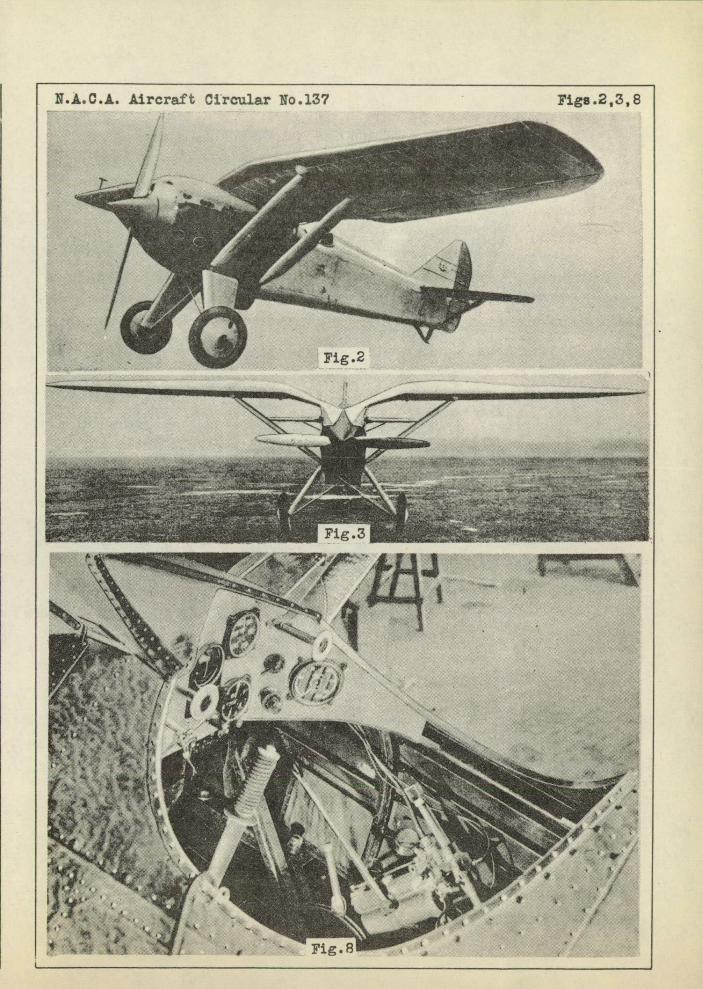
The P.1 and P.VIII airplanes differ in the type of engine
used, in their wing area and in their landing gears, the other
structural details being identical or presenting unimportant
variations (Figs. 1, 2, and 3).
The fuselage consists of two, principal independent parts
joined by chrome-nickel steel fittings and bolts. The front
part consists of a strong framework, to which are attached the
engine supports and accessories, as well as the wings and land-
ing gear. The, rear part, of rectangular cross section, contains
the pilot's cockpit and supports the tail surfaces. The rear
portion of the fuselage is covered with removable elektron pan-
els. The height of the pilot's seat can be adjusted during
flight within a range of 11 cm (4.3 in.). It has a windshield
and a board for the instruments which are arranged in two groups
at the right and left of the pilot t s hand (Fig. s). The two
machine guns are mounted in the middle, directly in front of the
pilot. The fuselage is constructed entirely of duralumin sec-
tions joined by rivets and sheet-duralumin fittings. The fuselage
structure is perfectly rigid and contains no cables nor brace
wires. *From a pamphlet published by the P.Z.L. (Polish National Air-'
craft Factory).
2 N.A.C.A. Aircraft Circular Yo. 137
The metal propeller is driven by a Hispano-Suiza 12 Lb or
Mc engine. The oil tank is under the engine, its outside wall
forming a radiator. In the P.1 the fuel tanks are placed syri-
metrically in the wings. In the P.VIII the principal tank is
situated in the fuselage, while there are two. small gravity
tanks inthé wings. The engine has . removable heet-e1ektron
housing provided with inspeOtlon ports. Access is gained to
all parts of the--engine by-'removing the óiivIing. Theegine is
separated from the pilot's cockpit by a fire wail. 'Kfire
alarm and extinguisher complete the equipment.
The P.1 and P.VIII both have two wings of variable section
and characteristic curvature. In the iiiii this curvature is
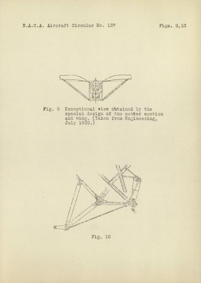
less pronounced than in the P.1; E 'ach' 'iving is attached by two
bolts to the sides of the raised portion of the fuselage which
is curved to form a prolongation of the upper curve of the
wings (Fig. 9). The plan form of the wings is tapering with
rounded tips. Each wing is suppotCdby two trüt passing
from the spars tothe lower edge of'-the-fuselage. The wing
structure consists of two I spars rigidly bräcèd by ribs to
which the corrugated metal covering is attached. The leading
edge is made of smooth sheet metal-on-formers attached to the
front spar. It has six inspectioh ports. Despite their rela-
tively small weight, the wings areexcéedingly strong and rigid.
The narrow ailerons have the form of rigid duralumin boxes
covering nearly the whole length of the wings. Each aileron
N.A.C.A. Aircraft Circular No. 137 3
has a single spar in the axis of rotation at a distance of one-
fifth its chord from the leading edge and is thus perfectly
balanced.
The rear end, of the fuselage carries the tail surfaces,
consisting of the stabilizer, elevator, fin and rudder. The
stabilizer can be adjusted during flight by rotation about its
rear spar. It is braced against the lower edge of the fuselage
by two adjustable tubular struts. The elevator and rudder are
not balanced. These and the ailerons are mounted on ball bear-
ings.
The controls comprise the control stick and rudder bar.
The motion of the former is transmitted to the ailerons through
two levers, a vertical tube and rigid controls covering the
length of the wing spars. The controls are mounted on ball
bearings. The control cables are inside the fuselage. There
are no pulleys which might impede the cables.
The landing gears of the P.1 and P.VIII differ in certain
details, although made on the same general principle. Figure
10 gives a good idea of these details, whose advantages are:
1. A wide track,
2. Elimination of axle,
3. Good conditions for the functioning of the oleopneu-
matic shock absorber placed inside the fuselage near the engine
and hence protected from dust and low temperatures.
This landing gear produces very little drag. Before adop-
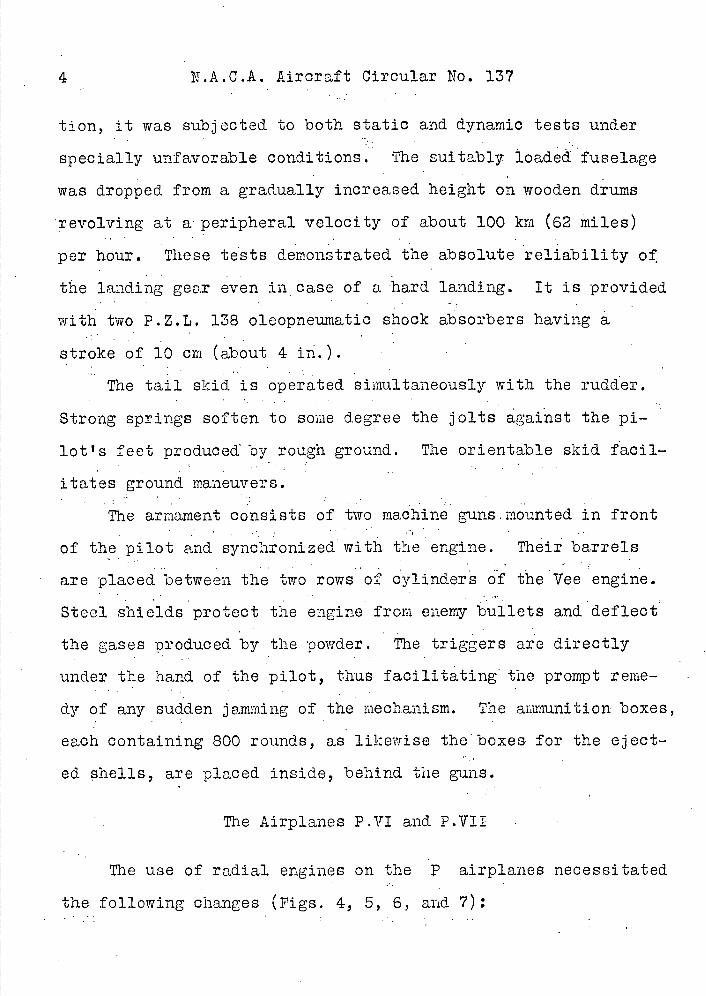
4 N.A.C.A. Aircraft Circular No. 137
tion, it was subjected to both static and dynamic tests under
specially unfavorable conditions. The suitably loaded fuselage
was dropped from a gradually increased height on wooden drums
revolving at a peripheral velocity of about 100 km (62 miles)
per hour. These tests demonstrated the absolute reliability of
the landing gear even in case of a hard landing. It is provided
with two P.Z.L. 138 oleopneumatic shock absorbers having
stroke of 10 cm (about 4 in.).
The tail skid is operated simultaneously with the rudder.
Strong springs soften to some degree the jolts against the pi-
lot's feet produced' by rough ground. The orientable skid facil-
itates ground maneuvers.
The armament consists of two machine guns-mounted in front
of the pilot and synchronized with the engine. Their barrels
are placed between the two rows of cylinders of the Vee engine.
Steel shields protect the engine from enemy bullets and deflect
the gases produced by the powder. The triggers are directly
under the hand of the pilot, thus facilitating the prompt reme-
dy of any sudden jamming of the mechanism. The ammunition boxes,
each containing 800 rounds, as likewise the boxes for the eject-
ed shells, are placed inside, behind the guns.
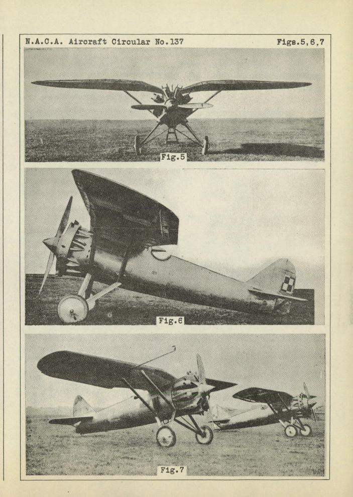
The Airplanes P.VI and P.VIi
The use of radial engines on the P airplanes necessitated
the following changes (Figs. 4, 5, 6, and 7):
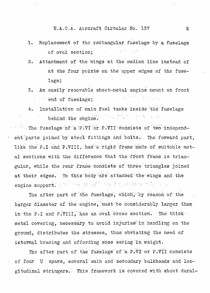
N.A.C.A. Aircraft Circular No. 137 5
1. Replacement of the rectangular fuselage by a fuselage
of oval section; 0
2. Attachment of the wings at the median line instead of
at the four points on the upper edges of the fuse-
lage;
3. An easily removable sheet-metal engine mount on front
end of fuselage; 0
4. Installation of main fuel tanks ins ictéthefuselage
behind the 'engine.
of tvoindepend-
ent parts joined by stei el fittings andbol't.. The forward :part,
like the P.1 and P.VIiI, haá a rigid frame rtiè of suitable met-
al sections with the difference that the fbnt frame is trian-
gular, while the rear frane consists of three triangles joined
at their edges. To this body- are atthchedthewings and the
engine support.*upport ..........................; •••. ......
0
The after part of thefiiselage, wh1ch by reason of the
larger diameter of th ....enine,mustbe considerably larger than
in ±he P.1 and PVIII,has an oval cross section. The thick
metal covering, necessary to avoid inju±iesiñ handling on the
ground, distributes the stresses, thus obviating the need of
internal bracing and affording ...ône saving in weight.
The after part of the fuselage of PVIorP.VII consists
of four U spars, AeveaI main and secondary bulkheads and lon-
gitudinal stringers. This framework is covered with sheet dural-
6 N.A.C.A'. Aircraft Circular io. 137
umin and forms a rigid streamlined body, which offers great re-
sistance to torsional stresses.
Thc fuselage contains the adjustable pilot's seat and the
controls. The instruments are conv.oniently arranged on a suita-
ble board. Due to the relatively large dimensions of the fuse-
lage, the pilot's cabin is roomy..and comfortable. The pilot is
protected by a windshield. The machine-gun supports are on both
sides of cockpit,. about halfway up.
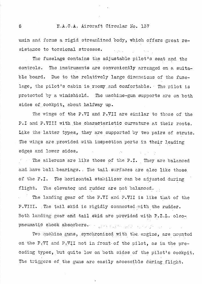
The wings of the P.111 and P.VII are similar to those of the
P.1 and P.VIII with the characteristic curvature at their roots.
Like the latter types, they are supported by two pairs of struts.
The wings are provided with inspection ports in their leading
edges and lower sides. . . ".
'The ailerons are like those of the P.I. They are balanced
and. have ball bearings. The tail . sur'ac,es are also like those,
of the P.I. The horizontal stabilizer can be adjusted during
flight. The elevator and rudder are no.t balanced.
The landing gear of the P.111 and P.1111 is like that of the
P.11111. The tail skid is.rigidiy conne,ctedvr.it.h the rudder.
Both 1andig gear 'ad tail :skid are provided with P.Z.L.. o.leo-,
pneu.mati.c shock absorbers...,.. .........' ' Two iaohine guns, : synchronized with the, engine, are mounted
on -the P.111 and P.1111 not in front-of the pilot, as in the pre-
ceding types, but quite low on both sides of the pilot's cockpit.
The triggers of the guns are easily accessible during,flight.
N.A.C.A. Aircrat Circular No. 137
There are large inspection ports in the fuselage which render
the inspection of the guns exceptionally easy on the ground.
The engines on the P.VI and P.VII are cowled differently,
now consisting of:
1. A partially open cowling in which the cylinder heads
are exposed to the direct action of the air. This type can be
supplemented by a Townend ring.
2. A closed cowling completely enclosing each individual
cylinder. This cowling has an elongated frontal orifice through
which the air is directed toward the interior of the cowling by
means of partitions so disposed as to insure the best possible
cooling of the cylinder heads and exhaust valves.
In both systems complete access may be had to the cylinders
by removing the cowlings. The second type of cowling gives ex-
cellent results from both the fineness and thermal viewpoints.
Its only disadvantage consists of certain difficulties in making
the cowlings. The first type is much easier to make, but does
not give so great fineness. It is to be recommended, however,
because of its simplicity and greater facility of removal.
The N.A.C.A. cowling can also be used.
N.A.0.A. Aircraft Ci.rcular No. 137
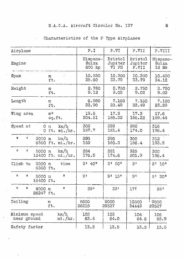
Characteristics of the P Type Airplanes
Airplane - P.1 P.VI P.VII P.VIII
Hispano- Bristol Bristol Hispano-Engine Suiza Jupiter Jupiter Suiza
600 hp VI FH F.VII 12 Mc
10.850 10.300 10.300 10.400 Span m ft. 35.60 33.79 33.79 34.12
Height m 2.780 2.750 2.750 2.750 ft. 9.12 9.02 9.02 9.02
Length m 6.980 - 7.160 - 7.160 7,100 ft. 22.90 23.49 23.49 23.29
Wing area m2 19.5 17.3 17.3 17.6 sq.ft. 204.51 186.22 186.22 189.44
Speed at 0 m km/h 302 292 280 - 316 0 ft. mi./hr. 187.7 181.4 174.0 196.4
U U 2000 iii km/h 293 290 300 312 6560 ft. mi./hr. 182 180.2 186.4 193.9
II U 5000 m km/h 284 281 325 300 10, 400 ft. niL/hr. 176.5 174.6 201.9 186.4
Climb to 2000 m time 2' 40" 2' 50" 3' 21 iOn 6560 ft.
It 5000 m II 9? 91 15" 91 8' 30" 16400 ft.
U It 8000.m if 29' 33' 17 28' 26247 ft.
Ceiling m 8600 9000 10500 9000 ft. 28215 29527 34449 29527
Minimum speed km/h 102 [ 103 104 106 near ground mi./hr. 63.4 64.0 64.6 65.9
Safety factor 13.5 13.5 13.5 13.5
N.A.C.AS Aircraft Circular No. 137
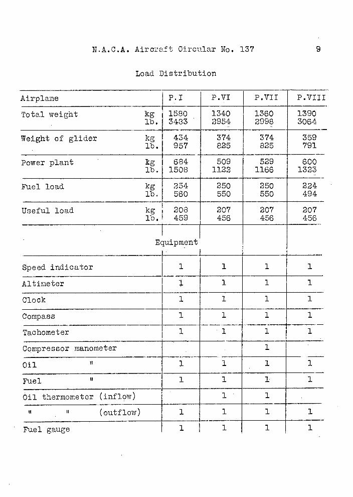
Load Distribution
Airplane P.1 P.VI P.1111 P.11111
Total weight kg lb.1
1 1580 3483
1340 2954
1360 2998
1390 3064
Weight of glider kg 1's.
434 957
374825
374 825
359 791
Power plant kg lb.
Fuel load kg lb.
684 1508
254 560
509 1122
250 550
529 1166
250 550
600 1323
224 494
Useful load kg lb. 1
208 459
207 456
207 456
207 456
Equipment
Speed indicator
Altimeter 1 T 1
Clock
Corffpass
1
1
1
1
1
1
1
1
Tachometer 1 1 1 1
Compressor manometer 1
Oil 11 1 1 1 1
Fuel It 1 1 1 1
Oil thermometer (inflow) 1 1
It It (outflow) 1 1 1 1
Fuel gauge - 1 1 1 1
N.A.C.A. Aircraft Circular No. 137 10
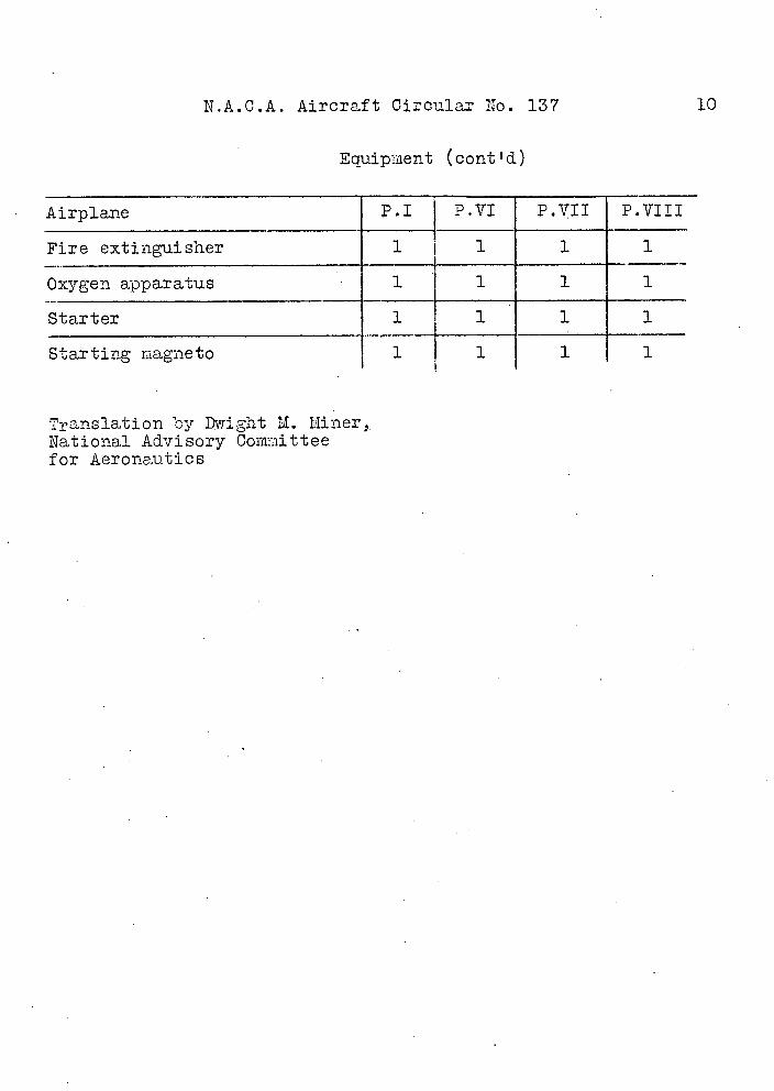
Equip:nent (cont 'd)
Airplane P.1 P.VI P.VII P.VIII
Fire extinguisher 1 1 1 1
Oxygen apparatus 1 1 1 1
Starter 1 1 1 1
Starting magneto 1 1 1 1
Translation by Dwight M. Miner,. National Advisory Committee for Aeronautics
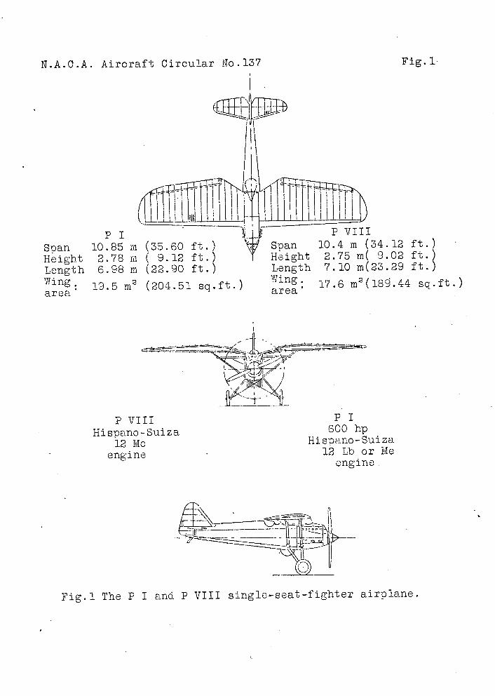
P VIII Hispano - Suiza
12 Mc engine
P1 600 hp
Hispano- Suiza 12 Lb or Me
engine.
N.A.0.A. Aircraft Circular No-137
Fig. 1
P I P VII I
Span 10.85 in (35.60 ft.) \ Span 10.4 m (34.12 ft.)
Height Length
2.78 in 6.98 in
( 9.12 ft.) T (22.90 ft.)
Height Length
2.75 m( 9.02 7.10 m(23.29
ft.) ft.)
19.5 in 2 (204.51 sq.ft.) 17.6 M2 (18-9.44 sq.ft.) area area
Fig.1 The P I and P VIII single-seat-fighter airplane.
- -
N.A.C.A. Aircraft Circular No.137 Figs .2,3,8
r r 40
L
: . * ' 1 •'' .
.&T:•'
/
19 4
( It:;
er .1
I'1.A.C.A. Aircraft Circular No.1j37
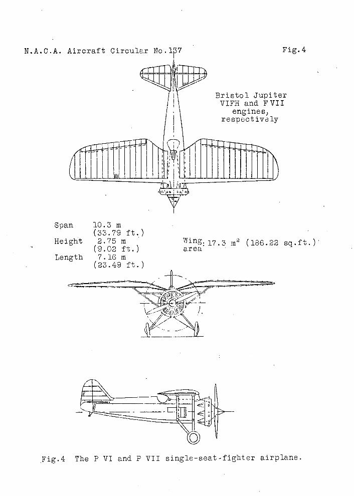
Fig. 4
Span 10.3 m (33.79 ft.)
Height 2.75 m (9.02 ft.)
Length 7.16 m (23.49 ft.)
Wing. 17.3 m2 (186.22 eq.ft.) area
--
Fig.4 The P VI and P VII single-seat-fighter airplane.
Ie
FIg • 7 -;
N.A.C.A. Aircraft Circular No.137
Yige.5, 6,7
N.A.C.A. Aircraft Circular No. 137
Figs. 9,10
Fig. 9 Exceptional view special design of and wing. (Taken July 1930.)
chtained by the the center section from Enineering,
\\
/11 zr. I,-- -
T
Fig. 10