it6263 datasheet v0.8
DESCRIPTION
aTRANSCRIPT

www.ite.com.tw Mar-2010 Rev:0.8 1/16
IT6263
Single Chip De-SSC LVDS to HDMI Converter
Preliminary Datasheet
ITE TECH. INC.
IT6263
www.ite.com.tw Mar-2010 Rev:0.8 2/16
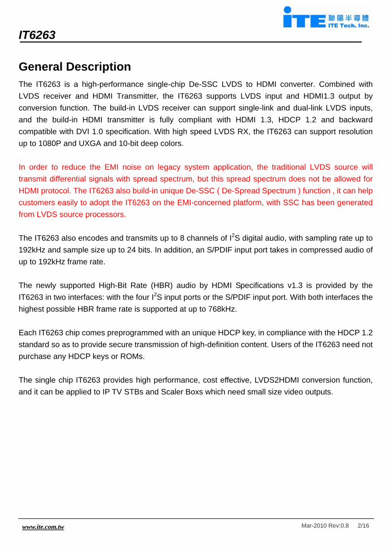
General Description The IT6263 is a high-performance single-chip De-SSC LVDS to HDMI converter. Combined with LVDS receiver and HDMI Transmitter, the IT6263 supports LVDS input and HDMI1.3 output by conversion function. The build-in LVDS receiver can support single-link and dual-link LVDS inputs, and the build-in HDMI transmitter is fully compliant with HDMI 1.3, HDCP 1.2 and backward compatible with DVI 1.0 specification. With high speed LVDS RX, the IT6263 can support resolution up to 1080P and UXGA and 10-bit deep colors. In order to reduce the EMI noise on legacy system application, the traditional LVDS source will transmit differential signals with spread spectrum, but this spread spectrum does not be allowed for HDMI protocol. The IT6263 also build-in unique De-SSC ( De-Spread Spectrum ) function , it can help customers easily to adopt the IT6263 on the EMI-concerned platform, with SSC has been generated from LVDS source processors. The IT6263 also encodes and transmits up to 8 channels of I2S digital audio, with sampling rate up to 192kHz and sample size up to 24 bits. In addition, an S/PDIF input port takes in compressed audio of up to 192kHz frame rate. The newly supported High-Bit Rate (HBR) audio by HDMI Specifications v1.3 is provided by the IT6263 in two interfaces: with the four I2S input ports or the S/PDIF input port. With both interfaces the highest possible HBR frame rate is supported at up to 768kHz. Each IT6263 chip comes preprogrammed with an unique HDCP key, in compliance with the HDCP 1.2 standard so as to provide secure transmission of high-definition content. Users of the IT6263 need not purchase any HDCP keys or ROMs. The single chip IT6263 provides high performance, cost effective, LVDS2HDMI conversion function, and it can be applied to IP TV STBs and Scaler Boxs which need small size video outputs.

IT6263
www.ite.com.tw Mar-2010 Rev:0.8 3/16
Features ( LVDS RX )
• Support LVDS Input modes: Single Link, Dual Link
• Support input clock rate up to 150MHz
• Support input color depth up to 10bit
• Support De-SSC ( De-Spread Spectrum )
• Support Data Mapping: Open LDI, JEIDA, VESA
Features ( HDMI TX)
• HDMI 1.3 transmitter
• Compatible with HDMI 1.3, HDCP1.2 and DVI 1.0 specifications
• Support deep color depth up to 12bit
• Support link speeds of up to 2.25Gbps (link clock rate of 225MHz )
• Support Gammat Metadata packet
• Digital audio input interface supporting o up to four I2S interface supporting 8-channel audio, with sample rates of 32~192 kHz
and smaple sizes of 16~24 bits o S/PDIF interface supporting PCM, Dolby Digital, DTS digital audio at up to 192kHz frame
rate o Support for high-bit-rate (HBR) audio such as DTS-HD and Dolby TrueHD through the
four I2S interface or the S/PDIF interface, with frame rates as high as 768kHz o Compatible with IEC 60958 and IEC 61937 o Audio down-sampling of 2X and 4X
• Software programmable, auto-calibrated TMDS source terminations provide for optimal source
• Software programmable HDMI output current level
• MCLK input is optional for audio operation. Users could opt to implement audio input interface
with or without MCLK
• Integrated pre-programmed HDCP keys
• Purely hardware HDCP engine increasing the robustness and security of HDCP operation
IT6263
www.ite.com.tw Mar-2010 Rev:0.8 4/16
• Monitor detection through Hot Plug Detection and Receiver Termination Detection
• Embedded full-function pattern generator
• Intelligent, programmable power management
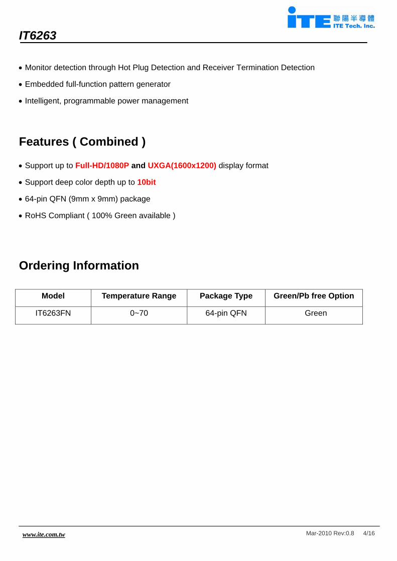
Features ( Combined )
• Support up to Full-HD/1080P and UXGA(1600x1200) display format
• Support deep color depth up to 10bit
• 64-pin QFN (9mm x 9mm) package
• RoHS Compliant ( 100% Green available )
Ordering Information
Model Temperature Range Package Type Green/Pb free Option
IT6263FN 0~70 64-pin QFN Green

IT6263
www.ite.com.tw Mar-2010 Rev:0.8 5/16
Pin Diagram
17181920212223242526272829303132
XTALOUT
PCSDA
ANV
DD
XTALIN
11
12
13
14
SCL_MCLK
OVDD
IVDD
PCADR
1
2
3
4
5
6
7
8
9
IVDD
TXREXT
PVCC
1
TXCM
TXCP
TXAVC
C18
TX0M
TXAVC
C18
TX2M
TXAVC
C33
TX0P
TX1M
SYSRSTNTXHPD
DDCSCLDDCSDA
I2S3I2S2
I2S1I2S0
WS_SPDIF
TX2P
PVCC
2
10
15
16
38
37
36
35
48
47
46
45
44
43
42
41
40
39
34
33
64636261605958575655545352515049
IT6263LVDS to HDMIQFN-64 9x9
(Top View)R
XN
A1
RX
PB
1
RX
NB
1
AVC
C
RX
PA
1
ANV
DD
RXP
CLK
RXN
CLK
RX
PC
1
RXN
C1
RX
PE
1
RX
NE
1
RX
PD
1
RXN
D1
APV
DD
PCSCLIVDD
ANVDDRXNA2
RXPA2RXNB2
RXPB2
AVCCRXNC2RXPC2
ANVDD
RXND2RXPD2
RXNE2RXPE2 TXEMEM_VPP
TX1P
IVDD
Figure 1. IT6263 pin diagram

IT6263
www.ite.com.tw Mar-2010 Rev:0.8 6/16
Pin Description LVDS front-end interface pins Pin Name Direction Description Type Pin No.
RXNA1 Analog LVDS first link negative input LVDS 18
RXPA1 Analog LVDS first link positive input LVDS 19
RXNB1 Analog LVDS first link negative input LVDS 20
RXPB1 Analog LVDS first link positive input LVDS 21
RXNC1 Analog LVDS first link negative input LVDS 23
RXPC1 Analog LVDS first link positive input LVDS 24
RXND1 Analog LVDS first link negative input LVDS 28
RXPD1 Analog LVDS first link positive input LVDS 29
RXNE1 Analog LVDS first link negative input LVDS 30
RXPE1 Analog LVDS first link positive input LVDS 31
RXNCLK Analog LVDS negative clock input LVDS 25
RXPCLK Analog LVDS positive clock input LVDS 26
RXNA2 Analog LVDS second link negative input LVDS 37
RXPA2 Analog LVDS second link positive input LVDS 38
RXNB2 Analog LVDS second link negative input LVDS 39
RXPB2 Analog LVDS second link positive input LVDS 40
RXNC2 Analog LVDS second link negative input LVDS 42
RXPC2 Analog LVDS second link positive input LVDS 43
RXND2 Analog LVDS second link negative input LVDS 45
RXPD2 Analog LVDS second link positive input LVDS 46
RXNE2 Analog LVDS second link negative input LVDS 47
RXPE2 Analog LVDS second link positive input LVDS 48
XTALIN Analog Crystal clock input Analog 33
XTALOUT Analog Crystal clock output Analog 34
HDMI front-end interface pins Pin Name Direction Description Type Pin No.
TX2P Analog HDMI Channel 2 positive output TMDS 61
TX2M Analog HDMI Channel 2 negative output TMDS 60
TX1P Analog HDMI Channel 1 positive output TMDS 58
TX1M Analog HDMI Channel 1 negative output TMDS 57
TX0P Analog HDMI Channel 0 positive output TMDS 56
TX0M Analog HDMI Channel 0 negative output TMDS 55

IT6263
www.ite.com.tw Mar-2010 Rev:0.8 7/16
TXCP Analog HDMI Clock Channel positive output TMDS 53
TXCM Analog HDMI Clock Channel negative output TMDS 52
TREXT Analog External resistor for setting TMDS output level. Default tied to
TXAVCC18 via a 698-Ohm SMD resistor.
Analog 50
Digital Audio Input Pins Pin Name Direction Description Type Pin No.
SCL_MCLK Input I2S serial clock input /Audio master clock input LVTTL 13
WS_SPDIF Input I2S word select input /S/PDIF audio input LVTTL 12
I2S0 Input I2S serial data input LVTTL 9
I2S1 Input I2S serial data input LVTTL 8
I2S2 Input I2S serial data input LVTTL 7
I2S3 Input I2S serial data input LVTTL 6
Programming Pins Pin Name Direction Description Type Pin No.
SYSRSTN Input Hardware reset pin. Active LOW (5V-tolerant) Schmitt 2
DDCSCL I/O I2C Clock for DDC (5V-tolerant) Schmitt 4
DDCSDA I/O I2C Data for DDC (5V-tolerant) Schmitt 5
PCSCL Input Serial Programming Clock for chip programming (5V-tolerant) Schmitt 15
PCSDA I/O Serial Programming Data for chip programming (5V-tolerant) Schmitt 16
PCADR Input Serial programming device address select LVTTL 14
TXHPD Input HDMI TX Hot Plug Detection (5V-tolerant) LVTTL 3
TXEMEM_VPP Input Must be tied low via a resistor. LVTTL 1
Power/Ground Pins Pin Name Description Type Pin No.
IVDD Digital logic power (1.8V) Power 10, 35, 49, 64
OVDD I/O Pin power (3.3V) Power 11
TXAVCC18 HDMI analog frontend power (1.8V) Power 54, 59
TXAVCC33 HDMI analog frontend power (3.3V) Power 63
PVCC1 HDMI frontend core PLL power (1.8V) Power 51
PVCC2 HDMI frontend Filter PLL power (1.8V) Power 62
AVCC LVDS frontend power (3.3V) Power 22, 41
ANVDD LVDS frontend analog power (1.8V) Power 17, 27, 36, 44
APVDD LVDS frontend PLL power (1.8V) Ground 32
GND Exposed GND pad Ground 65

IT6263
www.ite.com.tw Mar-2010 Rev:0.8 8/16
Block Diagram
Figure 2. The IT6263 block diagram
Configuration and Function Control The IT6263 includes two serial programming ports by default : one for interfacing with micro-controller, the other for accessing the DDC channels of HDMI link. The serial programming interface for interfacing the micro-controller is a slave interface, comprising PCSCL (Pin 15) and PCSDA (Pin 16). The micro-controller uses this interface to monitor all the statuses and control all the functions. Two device addresses are available, depending on the input logic level of PCADR (Pin 14). If PCADR is pulled high by the user, the device address is 0x9A. If pulled low, 0x98. The I2C interface for accessing the DDC channels of the HDMI link is a master interface, comprising DDCSCL (Pin 4) and DDCSDA (Pin 5). The IT6263 uses this interface to read the EDID data and perform HDCP authentication protocol with the sink device over the HDMI cable.

IT6263
www.ite.com.tw Mar-2010 Rev:0.8 9/16
LVDS Mapping Table Link 1 Mapping Table
MAPPING MODE MAPPING MODE LVDS OUTPUT
DATA Open LDI/
JEIDA VESA
LVDS OUTPUT
DATA Open LDI/
JEIDA VESA
T0 R14 R10 T0 R12 R16 T1 R15 R11 T1 R13 R17 T2 R16 R12 T2 G12 G16 T3 R17 R13 T3 G13 G17 T4 R18 R14 T4 B12 B16 T5 R19 R15 T5 B13 B17
RXA1
T6 G14 G10
RXD1
T6 NA NA T0 G15 G11 T0 R10 R18 T1 G16 G12 T1 R11 R19 T2 G17 G13 T2 G10 G18 T3 G18 G14 T3 G11 G19 T4 G19 G15 T4 B10 B18 T5 B14 B10 T5 B11 B19
RXB1
T6 B15 B11
RXE1
T6 NA NA T0 B16 B12 T1 B17 B13 T2 B18 B14 T3 B19 B15 T4 HSYNC HSYNC T5 VSYNC VSYNC
RXC1
T6 DE DE

IT6263
www.ite.com.tw Mar-2010 Rev:0.8 10/16
Link 2 Mapping Table MAPPING MODE MAPPING MODE LVDS
OUTPUT DATA
Open LDI/ JEIDA
VESA
LVDS OUTPUT
DATA Open LDI/
JEIDA VESA
T0 R24 R20 T0 R22 R26 T1 R25 R21 T1 R23 R27 T2 R26 R22 T2 G22 G26 T3 R27 R23 T3 G23 G27 T4 R28 R24 T4 B22 B26 T5 R29 R25 T5 B23 B27
RXA2
T6 G24 G20
RXD2
T6 NA NA T0 G25 G21 T0 R20 R28 T1 G26 G22 T1 R21 R29 T2 G27 G23 T2 G20 G28 T3 G28 G24 T3 G21 G29 T4 G29 G25 T4 B20 B28 T5 B24 B20 T5 B21 B29
RXB2
T6 B25 B21
RXE2
T6 NA NA T0 B26 B22 T1 B27 B23 T2 B28 B24 T3 B29 B25 T4 HSYNC HSYNC T5 VSYNC VSYNC
RXC2
T6 DE DE
T6 T5 T4 T3 T2 T1 T0
RXCLK
RXA/B/C/D/E*
CurrentCycle
PreviousCycle
T6 T5 T4 T3 T2 T1 T0T6 T5 T4 T3 T2 T1 T0
RXCLK
RXA/B/C/D/E*
CurrentCycle
PreviousCycle
Note: *=1 or 2, 1 for Link1, 2 for Link2

IT6263
www.ite.com.tw Mar-2010 Rev:0.8 11/16
De-SSC Advantage and Performance LVDS Input Conditions: Single Channel LVDS at 1080P ( Input Clk = 148.5MHz ) with +/- 5000ppm SSC LVDS Input. Output Results of HDMI Compliance Test (Measured HDMI Output Eye Diagram ): With ITE De-SSC Technology – Pass, Eye Diagram is Open. ( Fig. 2 ) Without De-SSC Technology – Fail, Eye Diagram is Closed and Blur. ( Fig. 3 )
Figure 3. HDMI Output Eye Diagram with De-SSC ( Pass )
Figure 4. HDMI Output Eye Diagram without De-SSC ( Fail )

IT6263
www.ite.com.tw Mar-2010 Rev:0.8 12/16
Electrical Specifications Absolute Maximum Ratings Symbol Parameter Min. Typ Max Unit
IVDD Core logic supply voltage -0.3 2.5 V
OVDD I/O pins supply voltage -0.3 4.0 V
TXAVCC18 HDMI analog frontend supply voltage -0.3 2.5 V
TXAVCC33 HDMI analog frontend supply voltage -0.3 4.0 V
PVCC1 HDMI core PLL supply voltage -0.3 2.5 V
PVCC2 Filter PLL supply voltage -0.3 2.5 V
AVCC LVDS frontend power -0.3 4.0 V
ANVDD LVDS frontend analog power -0.3 2.5 V
APVDD LVDS frontend PLL power -0.3 2.5 V
VI Input voltage -0.3 OVDD+0.3 V
VO Output voltage -0.3 OVDD+0.3 V
TJ Junction Temperature 125 °C
TSTG Storage Temperature -65 150 °C
ESD_HB Human body mode ESD sensitivity 2000 V
ESD_MM Machine mode ESD sensitivity 200 V Notes: 1. Stresses above those listed under Absolute Maximum Ratings might result in permanent damage to the device. 2. Refer to Functional Operation Conditions for normal operation. Functional Operation Conditions Symbol Parameter Min. Typ Max Unit
IVDD Core logic supply voltage 1.62 1.8 1.98 V
OVDD I/O pins supply voltage 2.97 3.3 3.63 V
TXAVCC18 HDMI analog frontend supply voltage 1.71 1.8 1.89 V
TXAVCC33 HDMI analog frontend supply voltage 2.97 3.3 3.63 V
PVCC1 HDMI core PLL supply voltage 1.62 1.8 1.98 V
PVCC2 Filter PLL supply voltage 1.62 1.8 1.98 V
AVCC LVDS frontend power 2.97 3.3 3.63 V
ANVDD LVDS frontend analog power 1.62 1.8 1.98 V
APVDD LVDS frontend PLL power 1.62 1.8 1.98 V
VCCNOISE Supply noise 100 mVpp
TA Ambient temperature 0 25 70 °C
Θja Junction to ambient thermal resistance °C/WNotes: 1. TXAVCC18, TXAVCC33, PVCC1, PVCC2, AVCC, ANVDD and APVDD should be regulated. 2. See System Design Consideration for supply decoupling and regulation.

IT6263
www.ite.com.tw Mar-2010 Rev:0.8 13/16
DC Electrical Specification Under functional operation conditions Symbol Parameter Pin Type Conditions Min. Typ Max UnitVIH Input high voltage1 LVTTL 2.0 V
VIL Input low voltage1 LVTTL 0.8 V
VT Switching threshold1 LVTTL 1.5 V
VT- Schmitt trigger negative going threshold
voltage1
Schmitt 0.8 1.1 V
VT+ Schmitt trigger positive going threshold
voltage1
Schmitt 1.6 2.0 V
VOL Output low voltage1 LVTTL IOL=2~16mA 0.4
VOH Output high voltage1 LVTTL IOH=-2~-16mA 2.4
IIN Input leakage current1 all VIN=5.5V or 0 ±5 μA
IOZ Tri-state output leakage current1 all VIN=5.5V or 0 ±10 μA
IOL Serial programming output sink current2 Schmitt VOUT=0.2V 4 16 mA
Vswing TMDS output single-ended swing3 TMDS RLOAD=50Ω
VLOAD=3.3V
REXT=698Ω
400 600 mV
IOFF Single-ended standby output current3 TMDS VOUT=0 10 μA
VTH Differential Input high threshold LVDS VCM = +1.2V 100 mV
VTL Differential Input low threshold LVDS VCM = +1.2V -100 mV
IIN Input current LVDS VCM =
+2.4V/0V
±6 μA
Notes: 1. Guaranteed by I/O design. 2. The serial programming output ports are not real open-drain drivers. Sink current is guaranteed by I/O design
under the condition of driving the output pin with 0.2V. In a real serial programming environment, multiple devices and pull-up resistors could be present on the same bus, rendering the effective pull-up resistance much lower than that specified by the I2C Standard. When set at maximum current, the serial programming output ports of the IT6263 are capable of pulling down an effective pull-up resistance as low as 500Ω connected to 5V termination voltage to the standard I2C VIL. When experiencing insufficient low level problem, try setting the current level to higher than default.
3. Internal source turned off. Limits defined by HDMI Specifications v1.3a Audio AC Timing Specification Under functional operation conditions Symbol Parameter Conditions Min. Typ Max UnitFS_I2S I2S sample rate Up to 8 channels 32 192 kHz
FS_SPDIF S/PDIF sample rate 2 channels 32 192 kHz

IT6263
www.ite.com.tw Mar-2010 Rev:0.8 14/16
Operation Supply Current Specification Symbol Parameter PIXELCLK Typ Max Unit
27MHz 47 48 mA
74.25MHz 96 97 mA
148.5MHz 166 161 mA
IIVDD_OP IVDD current under normal operation
148.5MHz(DI)4 144 157 mA
27MHz 623 623 μA
74.25MHz 615 615 μA
148.5MHz 595 670 μA
IIOVDD_OP OVDD current under normal operation
148.5MHz(DI)4 672 672 μA
27MHz 34 38 mA
74.25MHz 36 40 mA
148.5MHz 39 43 mA
ITXAVCC18_OP TXAVCC18 current under normal operation
148.5MHz(DI)4 39 44 mA
27MHz 58 58 μA
74.25MHz 57 58 μA
148.5MHz 49 59 μA
ITXAVCC33_OP TXAVCC33 current under normal operation
148.5MHz(DI)4 50 59 μA
27MHz 2 2 mA
74.25MHz 5 5 mA
148.5MHz 7 11 mA
IPVCC1_OP PVCC1 current under normal operation
148.5MHz(DI)4 7 11 mA
27MHz 2 2 mA
74.25MHz 6 6 mA
148.5MHz 13 13 mA
IPVCC2_OP PVCC2 current under normal operation
148.5MHz(DI)4 13 13 mA
27MHz 28 30 mA
74.25MHz 36 38 mA
148.5MHz 47 51 mA
IANVDD_OP ANVDD current under normal operation
148.5MHz(DI)4 59 62 mA
27MHz 4 5 mA
74.25MHz 12 13 mA
148.5MHz 24 27 mA
IAPVDD_OP APVDD current under normal operation
148.5MHz(DI)4 13 14 mA
27MHz 9 10 mA
74.25MHz 9 10 mA
IAVCC_OP AVCC current under normal operation
148.5MHz 9 10 mA

IT6263
www.ite.com.tw Mar-2010 Rev:0.8 15/16
148.5MHz(DI)4 15 16 mA
27MHz 243 286 mW
74.25MHz 376 432 mW
148.5MHz 565 645 mW
WTOTAL_OP Total power consumption under normal operation3
148.5MHz(DI)4 547 656 mW Notes: 1. Typ: OVDD=TXAVCC33=AVCC=3.3V, IVDD=AVCC18=PVCC1=PVCC2=APVDD=ANVDD=1.8V
Max: OVDD=TXAVCC33=AVCC=3.6V, IVDD=AVCC18=PVCC1=PVCC2=APVDD=ANVDD=1.98V 2. PIXELCLK refer to the video clock 3. PIXELCLK=27MHz: 480p with 48kHz/8-channel audio,
PIXELCLK=74.25MHz: 1080i with 192kHz/8-channel audio, PIXELCLK=148.5MHz: 1080p with 192kHz/8-channel audio.
4. DI: LVDS Dual Link. 5. PWTOTAL_OP are calculated by multiplying the supply currents with their corresponding supply voltage and summing up all the items.

IT6263
www.ite.com.tw Mar-2010 Rev:0.8 16/16
Package Dimensions
Figure 5. 64-pin QFN Package Dimensions