it2 u03 - function of components
DESCRIPTION
IT2 U03 - Function Of Components - CompleteTRANSCRIPT
CGLI 2330 Certificate in Electrotechnical Technology Level 2 Installation Technology: Unit 205 – Installation (Buildings & Structures)
Unit 03 – Function Of Components
The College at Clacton Unit 03 Page 1 August 2011
Function of Components
Unit Aims
By the end of the unit participants should be able to:
State the function of components in electrotechnical systems a) Lighting
i) Switches ii) Lamps iii) terminals and connections
b) power and heating i) ring and radial circuits and sockets ii) cooking and water heating circuits iii) motors iv) industrial installations v) controls - thermostats, timers, meters, switch gear, detectors
c) security systems i) relays ii) detectors iii) controls iv) maintained and non maintained systems
d) data/communication systems i) cables and components
(Syllabus Reference: 4.3.07)
Function of Components
As discussed earlier, circuits are made up of a number of components the type of which depend on the type of circuit being dealt with. In this section we will look at the various types of components commonly encountered.
Lighting Circuits
Switches
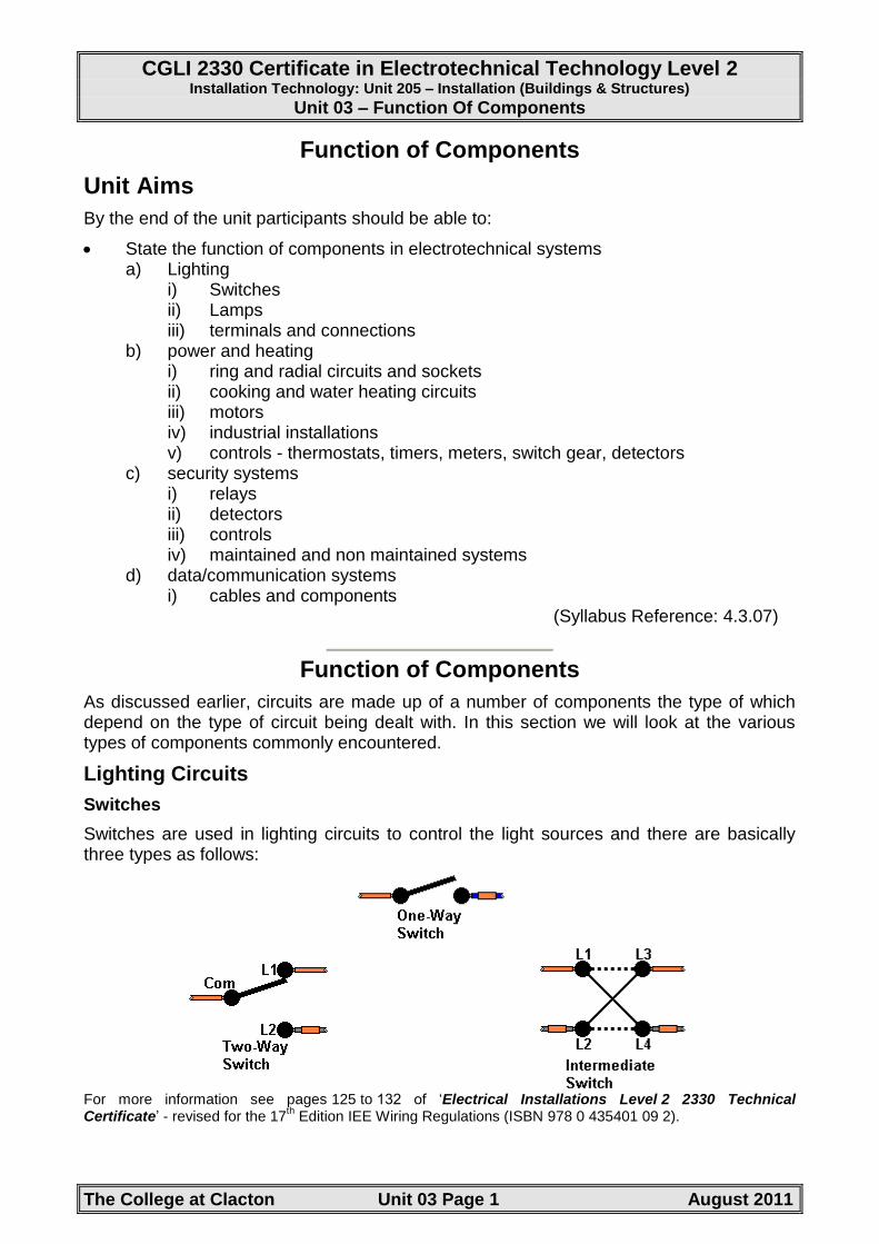
Switches are used in lighting circuits to control the light sources and there are basically three types as follows:
For more information see pages 125 to 132 of „Electrical Installations Level 2 2330 Technical Certificate‟ - revised for the 17
th Edition IEE Wiring Regulations (ISBN 978 0 435401 09 2).

CGLI 2330 Certificate in Electrotechnical Technology Level 2 Installation Technology: Unit 205 – Installation (Buildings & Structures)
Unit 03 – Function Of Components
The College at Clacton Unit 03 Page 2 August 2011
Lamps
These are components that convert the electrical energy in to light. The component containing the lamp and associated control gear (if applicable) is called a „LUMINAIRE‟. There are many different types of lamp in use with each having particular characteristics with each having a specific range of uses. Some of the more common are listed.
Incandescent Lamps
General Lighting Service (GLS) Lamp
The GLS incandescent lamp produces light as a result of the heating effect of an electric current flowing through a tungsten filament wire. Tungsten has a melting point of 3380°C and if the conditions are correct it can function in the incandescent mode within a few hundred degrees of this temperature. However, where considerable lasting power is required, such as for incandescent lamps that have an average life of 1 000 hours, the filament is kept to a much lower operating temperature of around 2500°C.
Tungsten filaments that are exposed to air at normal operating temperatures of 2500°C will quickly evaporate. For this reason the filament is situated inside a glass envelope (bulb) that has all the oxygen extracted.
GLS Lamp Data
efficacy ranges between 10 and 18 lumens per watt
reasonable colour rendering
pearl or clear bulb
can be operated in any position
average life 1 000 hours for standard GLS lamps
suitable for dimmer circuits
no control gear required – connected direct to the source of voltage
low initial cost
applications – domestic commercial and industrial uses
lamp designation – GLS
CGLI 2330 Certificate in Electrotechnical Technology Level 2 Installation Technology: Unit 205 – Installation (Buildings & Structures)
Unit 03 – Function Of Components
The College at Clacton Unit 03 Page 3 August 2011
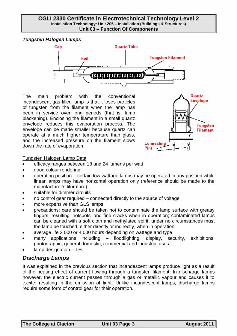
Tungsten Halogen Lamps
The main problem with the conventional incandescent gas-filled lamp is that it loses particles of tungsten from the filament when the lamp has been in service over long periods (that is, lamp blackening). Enclosing the filament in a small quartz envelope reduces this evaporation process. The envelope can be made smaller because quartz can operate at a much higher temperature than glass, and the increased pressure on the filament slows down the rate of evaporation.
Tungsten Halogen Lamp Data
efficacy ranges between 18 and 24 lumens per watt
good colour rendering
operating position – certain low wattage lamps may be operated in any position while linear lamps may have horizontal operation only (reference should be made to the manufacturer‟s literature)
suitable for dimmer circuits
no control gear required – connected directly to the source of voltage
more expensive than GLS lamps
precautions: care should be taken not to contaminate the lamp surface with greasy fingers, resulting „hotspots‟ and fine cracks when in operation; contaminated lamps can be cleaned with a soft cloth and methylated spirit. under no circumstances must the lamp be touched, either directly or indirectly, when in operation
average life 2 000 or 4 000 hours depending on wattage and type
many applications including – floodlighting, display, security, exhibitions, photographic, general domestic, commercial and industrial uses
lamp designation – TH.
Discharge Lamps
It was explained in the previous section that incandescent lamps produce light as a result of the heating effect of current flowing through a tungsten filament. In discharge lamps however, the electric current passes through a gas or metallic vapour and causes it to excite, resulting in the emission of light. Unlike incandescent lamps, discharge lamps require some form of control gear for their operation.

CGLI 2330 Certificate in Electrotechnical Technology Level 2 Installation Technology: Unit 205 – Installation (Buildings & Structures)
Unit 03 – Function Of Components
The College at Clacton Unit 03 Page 4 August 2011
Low Pressure Mercury Vapour Lamp
Low pressure mercury vapour lamps are better known as „Fluorescent Lamps‟ and they use the effect of phosphorescence to produce light. Two cathode filaments coated with electron emissive material are sealed into a glass tube which contains gases such as argon and krypton with a small quantity of liquid mercury, creating a low pressure region. The inside of the lamp is phosphor coated to produce the desired colour of light (for example, white, warm white and coolwhite).
Low Pressure Mercury Vapour Lamp Data
efficacy ranges between 38 and 104 lumens per watt
average life 12 000 hours
wide range of colour options available
low operating temperature
wide range of applications in domestic, commercial and industrial premises
dimming controls available
lamp designation – MCF.
Compact Fluorescent Lamp
This type of fluorescent lamp is compact in size to enable it to replace the incandescent lamp and they are often referred to as energy-saving lamps. They use about a fifth of the energy to produce the equivalent light output as the standard GLS incandescent lamp. The life of the lamp is also considerably longer, in the region of 10000 to 12000 hours, compared to around 1000 hours for the standard incandescent lamp.
There are many variations of this type of lamp, but they all serve the same purpose by reducing energy bills and lasting longer with increased efficacy (for example a 10 watt coolwhite lamp has an efficacy in the region of 60 lumens per watt).
The type of compact lamp shown in the diagram right is effectively one unit consisting of a tube and a ballast control. If the fluorescent tube or ballast fails, the complete unit has to be replaced. Other types of compact fluorescent lamps have separate tubes to that of the control arrangement.

CGLI 2330 Certificate in Electrotechnical Technology Level 2 Installation Technology: Unit 205 – Installation (Buildings & Structures)
Unit 03 – Function Of Components
The College at Clacton Unit 03 Page 5 August 2011
High Pressure Mercury Lamp
The inside arc tube of quartz allows more ultraviolet light to be transmitted towards the inner phosphor coating of the outer bulb. This has the effect of increasing the light output and improving colour-rendering properties. The outer bulb is filled with nitrogen, or nitrogen/argon gas mixture, and maintains an even lamp temperature.
High Pressure Mercury Lamp Circuit Data
lamp efficacy 34-60 lumens per watt
adequate colour rendering
lamp takes time to reach its full brilliance
after switching off, it will not restart until the pressure inside the lamp has fallen
average lamp life 22 000 hours
applications: used where colour rendering is not of major importance, for example street lighting, car parks, floodlighting of buildings, general outdoor commercial and industrial uses
lamp designation – MBF

CGLI 2330 Certificate in Electrotechnical Technology Level 2 Installation Technology: Unit 205 – Installation (Buildings & Structures)
Unit 03 – Function Of Components
The College at Clacton Unit 03 Page 6 August 2011
High Pressure Metal Halide Lamp
Metal halide lamps (see diagram above) are similar to standard high-pressure mercury lamps but metal halides in the form of thallium, gallium and scandium, are added to the mercury. The inclusion of these halides improves efficacy and colour rendering properties when compared with the standard high-pressure mercury lamps).
High Pressure Metal Halide Lamp Circuit Data
lamp efficacy 80-108 lumens per watt
good colour rendering
better than MBF lamps
low power consumption and running costs
lamp takes time to reach its full brilliance
after switching off it will not restart until the pressure inside the lamp has fallen
average lamp life 15 000 hours
applications: suitable for any indoor or outdoor commercial and industrial uses where good quality lighting is required; for example, stores, exhibitions, sports stadia and TV lighting
metal halide lamps should be used in enclosed luminaires
lamp designation - MBI
the addition of fluorescent phosphor to the inside surface of the glass bulb (MBIF lamps) helps to improve the colour rendering properties of the lamp.

CGLI 2330 Certificate in Electrotechnical Technology Level 2 Installation Technology: Unit 205 – Installation (Buildings & Structures)
Unit 03 – Function Of Components
The College at Clacton Unit 03 Page 7 August 2011
Low Pressure Sodium Lamp and Control Circuit
Low pressure sodium lamps provide the highest luminous efficacy of all lamps in general use. The construction of the lamp is shown in the diagram above.
The control gear to start the lamp supplies a high voltage. The initial discharge is in the neon and argon gas (glows red). Heat from the discharge gradually vaporises the metallic sodium, causing the discharge to change from red to yellow. A significant reduction in lamp voltage occurs when complete vaporisation of sodium takes place.
Low Pressure Sodium Lamp Circuit Data
lamp efficacy 70-180 lumens per watt
poor colour rendering
low power consumption and running costs
lamp takes time to reach its full brilliance
low wattage lamps tend to re-strike fairly quickly after an interruption in supply but higher wattage lamps may take approximately 10 minutes
average lamp life 16 000 hours
applications: used where colour rendering is not of major importance, for example, roadways, motorways (good performance in foggy conditions), car parks, floodlighting of buildings, general outdoor commercial and industrial uses
lamp designation - SOX

CGLI 2330 Certificate in Electrotechnical Technology Level 2 Installation Technology: Unit 205 – Installation (Buildings & Structures)
Unit 03 – Function Of Components
The College at Clacton Unit 03 Page 8 August 2011
High Pressure Sodium Lamp
The main disadvantage of the low-pressure sodium lamp is its poor colour rendering property, producing a monochromatic yellow light. This characteristic limits its application to outdoor uses. However, if the temperature is increased inside the lamp and therefore the pressure, a much-improved colour of warm golden-white is produced. This improved property was made possible by having the inner arc tube made of translucent ceramic material using alumina which is capable of operating at temperatures up to 1500°C and withstanding hot sodium vapour (see diagram below).
High Pressure Sodium Lamp Circuit Data
lamp efficacy 67-139 lumens per watt
fairly good colour rendering
low power consumption and running costs
lamp takes time to reach its full brilliance
once a hot lamp is switched off, it will not restart until it cools
average lamp life 24 000 hours
applications: suitable for many indoor and outdoor commercial and industrial uses, for example sports arenas, warehouses, factories and floodlighting of buildings
lamp designation - SON
For more information see pages 332 to 334 of „Electrical Installations Level 2 2330 Technical Certificate‟ - revised for the 17
th Edition IEE Wiring Regulations (ISBN 978 0 435401 09 2).
Power and Heating
Ring and Radial Circuits and Sockets
Many electrical appliances can easily be connected and disconnected from the electrical supply by means of plugs and sockets. A plug top is connected to an appliance by a flexible cord that should normally be no longer than 2 metres. To comply with BS7671 Regulation 553.1.7, socket outlets should be located adjacent to where portable equipment is likely to be used. Pressing the plug top into a socket outlet connects the appliance to the source of supply. Socket outlets therefore provide an easy and convenient method of connecting portable electrical appliances to a source of supply.

CGLI 2330 Certificate in Electrotechnical Technology Level 2 Installation Technology: Unit 205 – Installation (Buildings & Structures)
Unit 03 – Function Of Components
The College at Clacton Unit 03 Page 9 August 2011
Socket outlets can be obtained in various ampere ratings but the 13-ampere flat pin type complying with BS1363 is the most popular for installations in Great Britain. Each 13-ampere plug top contains a cartridge fuse to give maximum potential protection to the flexible cord (but not the appliance which, if required, must be provided with additional protection).
In industrial installations increasing use is made of socket outlets complying with BS EN 60309-2 (old BS4343). These socket outlets and their associated plugs are very robust to deal with the more arduous conditions that they are likely to be used in and they are available in a number of voltages to suit a range of activities. These devices have a key-way which prevents a tool from one voltage being connected to the socket outlet of a different voltage. They are also colour-coded for ease of identification as follows:
Voltage Colour
400V Red
230V Blue
110V Yellow
50V White
25V Violet
Socket outlets may be wired to a Ring or radial final circuit. In order that every appliance can be fed from an adjacent and convenient socket outlet, the number of sockets is unlimited provided that the floor area covered by the circuit does not exceed that given in Table 8A (reproduced below) in Appendix 8 of the „On-Site Guide‟.
Table 8A - Final circuits using BS1363 Socket-Outlets and Connection Units
Minimum live conductor cross-sectional area* (mm2)
Type of circuit Overcurrent protective
device
Copper conductor
thermoplastic or thermosetting
insulated cables
Copper conductor
mineral insulated cables
Maximum Floor area
served
Rating A mm2 mm2 m2
1 2 3 4 5 6
A1 Ring 30 or 32 2.5 1.5 100
A2 Radial 30 or 32 4 2.5 75
A3 Radial 20 2.5 1.5 50

CGLI 2330 Certificate in Electrotechnical Technology Level 2 Installation Technology: Unit 205 – Installation (Buildings & Structures)
Unit 03 – Function Of Components
The College at Clacton Unit 03 Page 10 August 2011
For more information see pages 132 to 135 of „Electrical Installations Level 2 2330 Technical Certificate‟ - revised for the 17
th Edition IEE Wiring Regulations (ISBN 978 0 435401 09 2).
Cooking and Water Heating Circuits
Cooker circuits are usually a single outlet supplied from a separate protection device in the distribution board. The outlet is normally a double pole switch which controls the supply to the cooker. The distance horizontally between this outlet and the cooking appliance must not exceed 2 metres (On-Site Guide 8.4 of Appendix 8). The rating of the protection device and cable is determined on the basis that not all of the cooker will be switched on at the same time. Even once everything is switched on the thermal control devices, such as thermostats and simmerstats, would be continually switching sections off. Making allowance for this process is known as applying „diversity‟ (see Appendix 1 of the ON-Site Guide). So that calculations can be made as to the possible load of a domestic cooker a formula has been devised. This is as follows:
Take the first 10 amperes of the total possible being taken at 100% of load
The remainder, after the 10 amperes are taken off, are taken at 30%
Plus 5 amperes if a socket outlet is incorporated in the control unit.
Example
The assumed demand for a cooker which contains:
2 x 1.5kW hob plates 2 x 3.0kW hob plates 1 x 2.0kW oven/grill 1 x 4.0kW oven
Maximum total power = 15kW
Maximum current = P U0
= 15 x 1000 230
= 65.22A
CGLI 2330 Certificate in Electrotechnical Technology Level 2 Installation Technology: Unit 205 – Installation (Buildings & Structures)
Unit 03 – Function Of Components
The College at Clacton Unit 03 Page 11 August 2011
The assumed current demand, allowing for diversity, is:
the first 10 amperes are at 100% = 10A
that leaves 55.22 amperes at 30% = 16.57A
Total = 10 + 16.57
= 26.57A
This means that the cable supplying this cooker would have to have a rating of at least 26.57A. If the control unit contained a socket outlet the rating would have to be at least 31.57A.
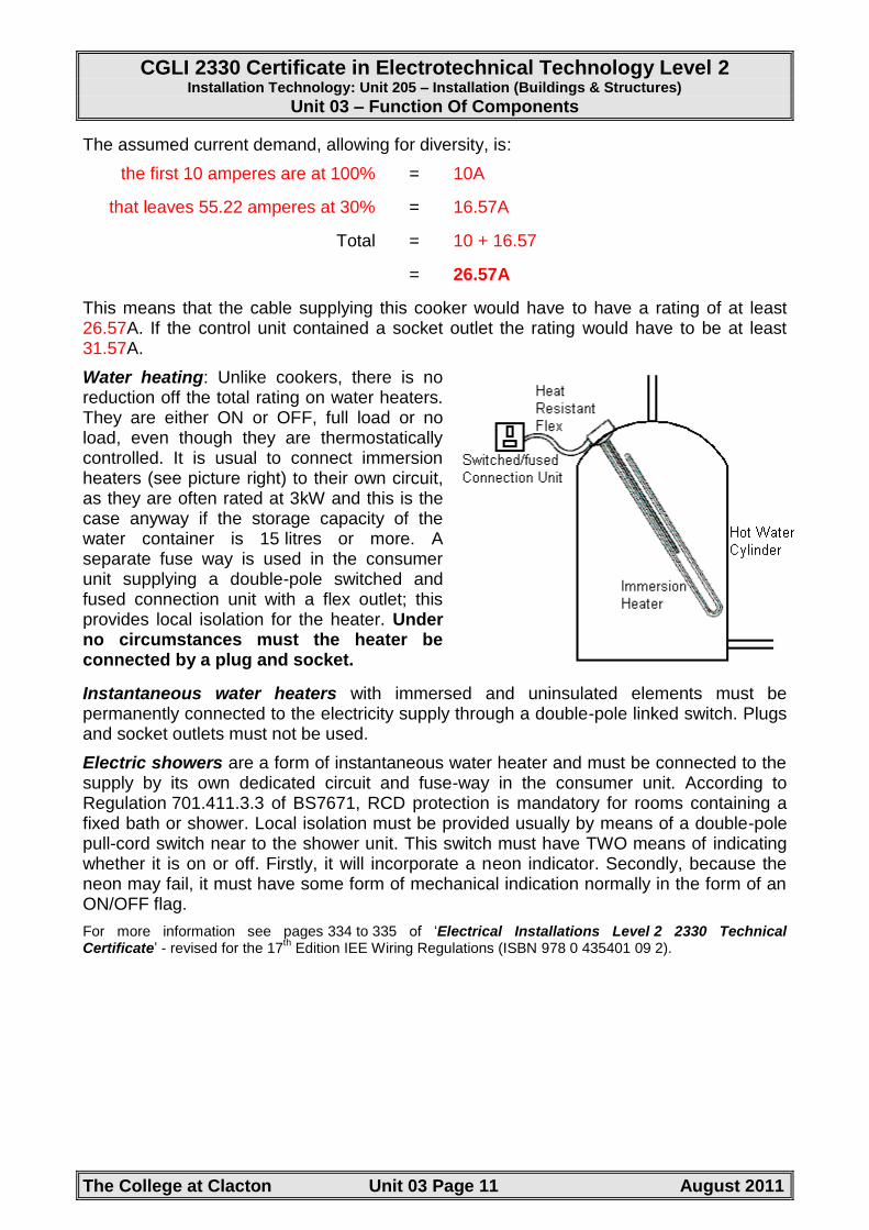
Water heating: Unlike cookers, there is no reduction off the total rating on water heaters. They are either ON or OFF, full load or no load, even though they are thermostatically controlled. It is usual to connect immersion heaters (see picture right) to their own circuit, as they are often rated at 3kW and this is the case anyway if the storage capacity of the water container is 15 litres or more. A separate fuse way is used in the consumer unit supplying a double-pole switched and fused connection unit with a flex outlet; this provides local isolation for the heater. Under no circumstances must the heater be connected by a plug and socket.
Instantaneous water heaters with immersed and uninsulated elements must be permanently connected to the electricity supply through a double-pole linked switch. Plugs and socket outlets must not be used.
Electric showers are a form of instantaneous water heater and must be connected to the supply by its own dedicated circuit and fuse-way in the consumer unit. According to Regulation 701.411.3.3 of BS7671, RCD protection is mandatory for rooms containing a fixed bath or shower. Local isolation must be provided usually by means of a double-pole pull-cord switch near to the shower unit. This switch must have TWO means of indicating whether it is on or off. Firstly, it will incorporate a neon indicator. Secondly, because the neon may fail, it must have some form of mechanical indication normally in the form of an ON/OFF flag.
For more information see pages 334 to 335 of „Electrical Installations Level 2 2330 Technical Certificate‟ - revised for the 17
th Edition IEE Wiring Regulations (ISBN 978 0 435401 09 2).
CGLI 2330 Certificate in Electrotechnical Technology Level 2 Installation Technology: Unit 205 – Installation (Buildings & Structures)
Unit 03 – Function Of Components
The College at Clacton Unit 03 Page 12 August 2011
Motors
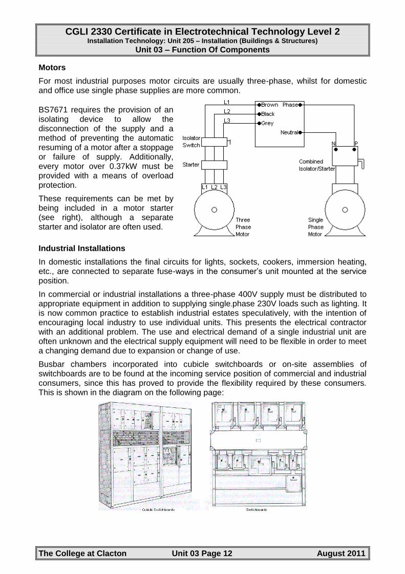
For most industrial purposes motor circuits are usually three-phase, whilst for domestic and office use single phase supplies are more common.
BS7671 requires the provision of an isolating device to allow the disconnection of the supply and a method of preventing the automatic resuming of a motor after a stoppage or failure of supply. Additionally, every motor over 0.37kW must be provided with a means of overload protection.
These requirements can be met by being included in a motor starter (see right), although a separate starter and isolator are often used.
Industrial Installations
In domestic installations the final circuits for lights, sockets, cookers, immersion heating, etc., are connected to separate fuse-ways in the consumer‟s unit mounted at the service position.
In commercial or industrial installations a three-phase 400V supply must be distributed to appropriate equipment in addition to supplying single-phase 230V loads such as lighting. It is now common practice to establish industrial estates speculatively, with the intention of encouraging local industry to use individual units. This presents the electrical contractor with an additional problem. The use and electrical demand of a single industrial unit are often unknown and the electrical supply equipment will need to be flexible in order to meet a changing demand due to expansion or change of use.
Busbar chambers incorporated into cubicle switchboards or on-site assemblies of switchboards are to be found at the incoming service position of commercial and industrial consumers, since this has proved to provide the flexibility required by these consumers. This is shown in the diagram on the following page:

CGLI 2330 Certificate in Electrotechnical Technology Level 2 Installation Technology: Unit 205 – Installation (Buildings & Structures)
Unit 03 – Function Of Components
The College at Clacton Unit 03 Page 13 August 2011
Distribution fuse boards, which may incorporate circuit breakers, are wired by sub-main cables from the service position to load centres in other parts of the building, thereby keeping the length of cable to the final circuit as short as possible. This is shown in the diagram below:
Controls - Thermostats, Timers, Meters, Switchgear, Detectors
Thermostats: When heating is carried out, whether it is space heating, water heating or for cooking, it is necessary to be able to control the heat reasonably accurately. A number of methods are employed for this purpose and the following notes will look at some of these.
The Bi-Metal Strip
A thermostat is a device for maintaining a constant temperature at some predetermined value. The operation of a thermostat is often based upon the principle of differential expansion between dissimilar metals that ultimately causes a contact to make or break at a chosen temperature.
A bimetal strip consists of two materials with different coefficients of expansion. These are fixed together at each end as shown in the diagram below (left).
When heat is applied the two materials will expand but at different rates. Because they are fixed together at either end and one is expanding more than the other one, the strip will start to deform and bend. The greater the heat rise, the greater will be the distortion. When the strip bends to a predetermined point, it can be arranged for it to operate an electrical contact controlling the load.

CGLI 2330 Certificate in Electrotechnical Technology Level 2 Installation Technology: Unit 205 – Installation (Buildings & Structures)
Unit 03 – Function Of Components
The College at Clacton Unit 03 Page 14 August 2011
Methods of Heat Control
Heat can be controlled in one of two ways:
Controlling power to load.
Thermostat.
In the first example, the amount of power supplied to the load is regulated, normally with no reference to the actual temperature achieved by the load. Methods used include the use of a „Three Heat Switch‟ and a „Simmerstat‟. In the second example, the actual temperature is measured and the load switched off when the temperature reaches a predetermined level and back on again when it falls below this level. Methods used include the use of an „Invar Rod‟ thermostat, „Bellows‟ type thermostat and a „Capillary Tube‟
Three Heat Switch
Some electric cookers are provided with a „Three Heat Switch‟. A circuit diagram of a three-heat switch is shown below:
When the switch is in the „High‟ position, the two heating elements, usually rated at 1 000 watts each, are connected in parallel across the supply. When the switch is turned to the „Medium‟ position, only one element is energised, so that the oven or grill is now operating at half its rating. When the switch is turned to the „Low‟ position, the two elements are connected in series across the supply, so that the oven or grill will now be operating at one quarter its rating. Thus, the heating effects produced by the three-heat switch are in the following proportions:
High - Full rating, say 2 000 watts Medium - Half rating, say 1 000 watts Low - Quarter rating, say 500 watts

CGLI 2330 Certificate in Electrotechnical Technology Level 2 Installation Technology: Unit 205 – Installation (Buildings & Structures)
Unit 03 – Function Of Components
The College at Clacton Unit 03 Page 15 August 2011
Simmerstat
A simmerstat is a device used to control the temperature of an electrical element, typically the boiling ring of a cooker. A snap-action switch is opened and closed at time intervals by passing current through a heater wrapped around a bimetal strip as shown below:
With the switch contact made, current flows through the load and the heating coil. The heater warms the bimetal strip which expands and opens out, pushing against the spring steel strip and the control knob, so opening the switch contacts. The load and the heating coil are then switched off and the bimetal strip cools to its original shape, which allows the contacts to close, and the process repeats. The load and heating coil are switched on and off frequently if the control knob is arranged to allow little movement of the bimetal strip. Alternatively, the heater will remain switched on for longer periods if the control knob is adjusted to allow a larger movement. In this way the temperature of the load is controlled.

CGLI 2330 Certificate in Electrotechnical Technology Level 2 Installation Technology: Unit 205 – Installation (Buildings & Structures)
Unit 03 – Function Of Components
The College at Clacton Unit 03 Page 16 August 2011
Invar Rod Thermostat
A rod type thermostat is often used with water heaters, particularly immersion heaters.
An „Invar‟ rod, which has minimal expansion when heated, is housed within a copper tube and the two metals are brazed together at the lower end. The copper tube is fixed to the thermostat housing at its upper end. The upper end of the invar rod is not secured but bears against the switch contact that will control the supply to the load, in this case, an immersion heater.
As the water heats up, the copper tube expands but the invar does not. This results in the top end of the invar being pulled downwards resulting in the switch contact opening thus disconnecting the load. As the water cools down the copper tube contracts causing the top end of the invar rod to move upwards causing the switch contact to close thus reconnecting the load.
The temperature adjustment screw moves the contact upward or downward varying the point at which the contacts open and close thus providing control over the temperature of the water.
Bellows Type Thermostat
The bellows type thermostat is commonly used to detect air temperature and is consequently used for controlling space heating systems, e.g. convector heaters and central heating. It works on the principle that as air temperature increases its volume will also increase. As can be seen from the diagram on the following page, as the volume increases, the bellows will open up which will eventually open the electrical contact controlling the heater. When the air temperature decreases, the air in the bellows will contract causing the bellows to close that will result in the electrical contact closing which initiates a call for heat. The purpose of the capillary tube and bulb is to make the thermostat much more sensitive to small changes in temperature.
Screwing the adjustment knob in or out will allow adjustment of the point at which the thermostat will switch on and off. The contacts are normally „snap action‟ to reduce the risk of them burning out.

CGLI 2330 Certificate in Electrotechnical Technology Level 2 Installation Technology: Unit 205 – Installation (Buildings & Structures)
Unit 03 – Function Of Components
The College at Clacton Unit 03 Page 17 August 2011
This type of thermostat can also be used in a refrigerator. If the contact is arranged to close when the temperature rises, it can be used to control the compressor in the refrigerator. Turning this on will cause the refrigerator to cool. When the temperature is low enough the bellows will contract and the contact will now open thus disconnecting the compressor.
Capillary Tube Thermostat.
This is the most widely used type of oven thermostat, slightly different versions also being used for washing machines and boilers.
The thermostat consists of a thermally sensitive phial, approximately 5mm in diameter, connected to the switch unit by a length of metal capillary tubing (see diagram below). Changes of temperature of the liquid in the phial are transmitted hydraulically through the capillary tube to a capsule in the switch unit. Movement of this capsule actuates a micro-gap switch when the desired temperature set by the control knob has been reached. An additional switch is sometimes fitted to provide double-pole isolation in the off position. The liquid in the phial is sensitive to temperature changes between 100 and 300°C. Ambient temperature compensation is incorporated to prevent changes in calibration due to heating of the switch unit.
Some ovens are provided with separate „bake‟ and „grill‟ elements, and a switch head can be obtained which incorporates a separate switch for each.
For more information see pages 337 to 339 of „Electrical Installations Level 2 2330 Technical Certificate‟ - revised for the 17
th Edition IEE Wiring Regulations (ISBN 978 0 435401 09 2).
CGLI 2330 Certificate in Electrotechnical Technology Level 2 Installation Technology: Unit 205 – Installation (Buildings & Structures)
Unit 03 – Function Of Components
The College at Clacton Unit 03 Page 18 August 2011
Security Systems
Fire Alarms Circuits
Through one or more of the various statutory Acts, all public buildings are required to provide an effective means of giving a warning of fire so that life and property may be protected. An effective system is one that gives a warning of fire while sufficient time remains for the fire to be put out and any occupants to leave the building.
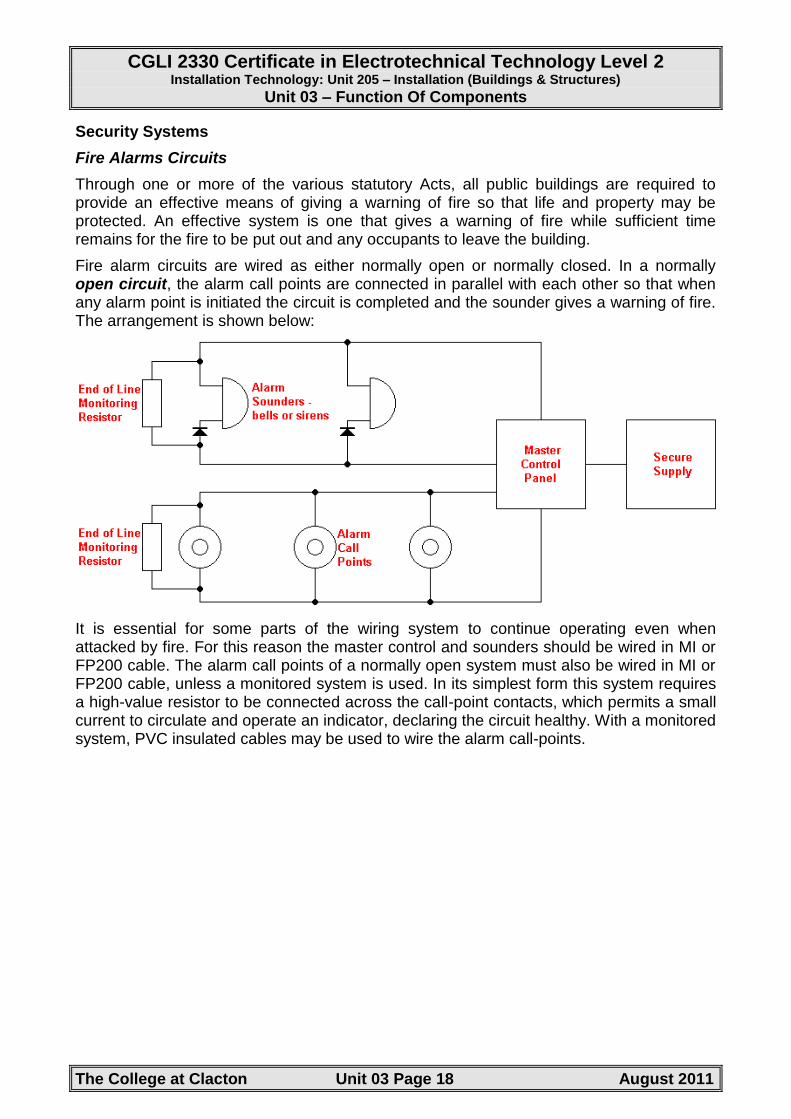
Fire alarm circuits are wired as either normally open or normally closed. In a normally open circuit, the alarm call points are connected in parallel with each other so that when any alarm point is initiated the circuit is completed and the sounder gives a warning of fire. The arrangement is shown below:
It is essential for some parts of the wiring system to continue operating even when attacked by fire. For this reason the master control and sounders should be wired in MI or FP200 cable. The alarm call points of a normally open system must also be wired in MI or FP200 cable, unless a monitored system is used. In its simplest form this system requires a high-value resistor to be connected across the call-point contacts, which permits a small current to circulate and operate an indicator, declaring the circuit healthy. With a monitored system, PVC insulated cables may be used to wire the alarm call-points.

CGLI 2330 Certificate in Electrotechnical Technology Level 2 Installation Technology: Unit 205 – Installation (Buildings & Structures)
Unit 03 – Function Of Components
The College at Clacton Unit 03 Page 19 August 2011
In a normally closed circuit, the alarm call points are connected in series to normally closed contacts as shown below:
When the alarm is initiated, or if a break occurs in the wiring, the alarm is activated. The sounders and master control unit must be wired in MI or FP200 cable, but the call points may be wired in PVC insulated cable since this circuit will always 'fail safe'.
Alarm Call Points: Manually operated alarm call points should be provided in all parts of a building where people may be present and should be located so that no one need walk more than 30 metres from any position within the premises in order to give an alarm. A manual break-glass call point is shown right:
They should be located on exit routes and, in particular, on the floor landings of staircases and exits to the street. They should be fixed at a height of 1.2 metres (top of call point) above the floor at easily accessible, well-illuminated and conspicuous positions.
Automatic detection of fire is possible with heat and smoke detectors. These are usually installed on the ceilings and at the top of stairwells of buildings because heat and smoke rise. Smoke detectors tend to give a faster response than heat detectors, but whether manual or automatic call points are used should be determined by their suitability for the particular installation. They should be able to discriminate between a fire and the normal environment in which they are to be installed.
Sounders: The position and numbers of sounders should be such that the alarm can be distinctly heard above the background noise in every part of the premises. The sounders should produce a minimum of 65 decibels, or 5 decibels above any ambient sound that might persist, for more than 30 seconds. Bells, hooters or sirens may be used but in anyone installation they must all be of the same type. Examples of sounders are shown on the following page:

CGLI 2330 Certificate in Electrotechnical Technology Level 2 Installation Technology: Unit 205 – Installation (Buildings & Structures)
Unit 03 – Function Of Components
The College at Clacton Unit 03 Page 20 August 2011
Fire Alarm Design Considerations: Since all fire alarm installations must comply with the relevant statutory regulations, good practice recommends that contact be made with the local fire prevention officer at the design stage in order to identify any particular local regulations and obtain the necessary certification.
Larger buildings must be divided into zones so that the location of the fire can be quickly identified by the emergency services. The zones can be indicated on an indicator board situated in, for example, a supervisor‟s office or the main reception area.
In selecting the zones, the following rules must be considered:
Each zone should not have a floor area in excess of 2000 m2.
Each zone should be confined to one storey, except where the total floor area of the building does not exceed 300 m2.
Staircases and very small buildings should be treated as one zone.
Each zone should be a single fire compartment. This means that the walls, ceilings and floors are capable of containing the smoke and fire.
At least one fire alarm sounder will be required in each zone, but all sounders in the building must operate when the alarm is activated.
An authorised person may silence the main sounders, once the general public have been evacuated from the building, but the current must be diverted to a supervisory buzzer that cannot be silenced until the system has been restored to its normal operational state.
A fire alarm installation may be linked to the local fire brigade's control room by the British Telecom network, if the permission of the fire authority and local BT office is obtained.
The electricity supply to the fire alarm installation must be secure in the most serious conditions. In practice the most reliable supply is the mains supply, backed up by a 'standby' battery supply in case of mains failure. The supply should be exclusive to the fire alarm installation, fed from a separate switch fuse, painted red and labelled, 'Fire Alarm - Do Not Switch Off‟. Standby battery supplies should be capable of maintaining the system in full normal operation for at least 24 hours and, at the end of that time, be capable of sounding the alarm for at least 30 minutes.

CGLI 2330 Certificate in Electrotechnical Technology Level 2 Installation Technology: Unit 205 – Installation (Buildings & Structures)
Unit 03 – Function Of Components
The College at Clacton Unit 03 Page 21 August 2011
Fire alarm circuits fall in to Band I for voltage that requires segregation from Band II circuits. However, BS7671 (Regulation 528-01-03) states “Fire alarm and emergency lighting circuits shall be segregated from all other cables and from each other in accordance with BS5839 and BS5266. Telecommunication circuits shall be segregated in accordance with BS6701 as appropriate”.
For more information see pages 343 to 349 of „Electrical Installations Level 2 2330 Technical Certificate‟ - revised for the 17
th Edition IEE Wiring Regulations (ISBN 978 0 435401 09 2).
Intruder Alarm Circuits
The circuitry of intruder alarms is very similar to that of fire alarms, the installation being wired as an open or closed circuit system as shown in previous diagrams. Instead of the alarm call points, pressure switches, proximity switches or motion detectors activate the intruder alarm installation.
It is usual to connect two sounders on an intruder alarm installation, one inside to make the intruder apprehensive and anxious, hopefully encouraging a rapid departure from the premises, and one outside. The outside sounder should be displayed prominently, since the installation of an alarm system is thought to deter the casual intruder and a ringing alarm encourages neighbours and officials to investigate a possible criminal act.
The supply must be secure, and this is usually achieved by a mains supply backed up by a battery standby supply. The alarm initiating switches detect an unauthorized entry into a building. They are provided in many forms and almost any combination may be installed to meet the requirements of a particular installation. The following information gives some indication of the characteristics of the various types.
Proximity Switches: They are designed for the discreet protection of doors and windows. They are made from moulded plastic and are about the size of a chewing gum packet. One moulding contains a reed switch, the other a magnet, and when they are placed close together the magnet maintains the contacts of the reed switch in either an open or closed position. Opening the door or window separates the two mouldings, and the switch is activated, triggering the alarm.
Pressure Pads: Pressure pad switches are placed under the carpet close to a door. Treading on the carpet activates the switch and the alarm system.
Passive Infrared Detectors: A moving body that is warmer than the surroundings activates these. They have a range of 15 metres and a detection zone of up to 360° but can be accidentally triggered by domestic pets.
Infrared Beam Detectors: These consist of a transmitter and receiver placed at opposite ends of a room up to 20 metres apart. Breaking the infrared beam activates the alarm system.
Ultrasonic Detectors: Any movement detected by the sensor triggers the alarm system. The detection range is variable between 2 and 8 metres.
General Considerations: The type and extent of the intruder alarm installation and, therefore, the cost, will depend upon many factors including the type and position of the building, the insurance risk involved and the peace of mind offered by an alarm system to the owner or occupier of the building.

CGLI 2330 Certificate in Electrotechnical Technology Level 2 Installation Technology: Unit 205 – Installation (Buildings & Structures)
Unit 03 – Function Of Components
The College at Clacton Unit 03 Page 22 August 2011
Intruder alarm circuits fall in to Band I for voltage and should be segregated from mains supply cables or insulated to the same standard as the highest voltage present if run in a common enclosure with Band II cables.
For more information see pages 349 to 353 of „Electrical Installations Level 2 2330 Technical Certificate‟ - revised for the 17
th Edition IEE Wiring Regulations (ISBN 978 0 435401 09 2).
Emergency Lighting (BS 5266: 1975)
Emergency lighting should be planned, installed and maintained to the highest standards of reliability and integrity, so that it will operate satisfactorily when called into action, no matter how infrequently this may be.
Emergency lighting is not required in private homes because the occupants are familiar with their surroundings, but in public buildings people are in unfamiliar surroundings. In an emergency people do not always act rationally, but well-illuminated and easily identified exit routes can help to reduce panic.
Emergency lighting is provided for two reasons; to illuminate escape routes, called „escape‟ lighting; and to enable a process or activity to continue after a normal lights failure, called „standby‟ lighting.
Local and national statutory authorities under legislative powers usually require escape lighting. The escape lighting scheme should be planned so that identifiable features and obstructions are visible in the lower levels of illumination that may prevail during an emergency. Exit routes should be clearly indicated by signs and illuminated to a uniform level, avoiding bright and dark areas.
Standby lighting is required in hospital operating theatres and in industry, where an operation or process once started must continue, even if the mains‟ lighting fails. Standby lighting may also be required for security reasons. The cash points in public buildings may need to be illuminated at all times to discourage acts of theft occurring during a mains lighting failure.
Emergency Supplies: Since an emergency occurring in a building may cause the mains supply to fail, the emergency lighting should be supplied from a source that is independent from the main supply. In most premises the alternative power supply would be from batteries, but generators may also be used. Generators can have large capacity and duration, but a major disadvantage is the delay time while the generator runs up to speed and takes over the load. In some premises a delay of more than 5 seconds is considered unacceptable, and in these cases a battery supply is required to supply the load until the generator can take over.
The emergency lighting supply must have an adequate capacity and rating for the specified duration of time (BS 7671 Regulation 313.2). BS 5266 states that after a battery is discharged by being called into operation for its specific duration of time, it should be capable of once again operating for the specified duration of time following a recharge period of not longer than 24 hours. The duration of time for which the emergency lighting should operate will be specified by a statutory authority but is normally 1-3 hours. BS 5266 states that escape lighting should operate for a minimum of 1 hour. Standby lighting operation time will depend upon financial considerations and the importance of continuing the process or activity.

CGLI 2330 Certificate in Electrotechnical Technology Level 2 Installation Technology: Unit 205 – Installation (Buildings & Structures)
Unit 03 – Function Of Components
The College at Clacton Unit 03 Page 23 August 2011
There, are two possible modes of operation for emergency lighting installations: maintained and non-maintained.
Maintained Emergency Lighting: The emergency lamps are continuously lit using the normal supply when this is available, and change over to an alternative supply when the mains supply fails. The advantage of this system is that the lamps are continuously proven healthy and any failure is immediately obvious. It is a wise precaution to fit a supervisory buzzer in the emergency supply to prevent accidental discharge of the batteries, since it is not otherwise obvious which supply is being used.
Maintained emergency lighting is normally installed in theatres, cinemas, discotheques and places of entertainment where the normal lighting may be dimmed or extinguished while the building is occupied. The emergency supply for this type of installation is often supplied from a central battery, the emergency lamps being wired in parallel from the low-voltage supply as shown below:
Non-Maintained Emergency Lighting: The emergency lamps are only illuminated if the normal mains supply fails. Failure of the main supply de-energizes a solenoid and a relay connects the emergency lamps to a battery supply, which is maintained in a state of readiness by a trickle charge from the normal mains supply. When the normal supply is restored, the relay solenoid is energized, breaking the relay contacts, which disconnects the emergency lamps, and the charger recharges the battery. The diagram below shows this arrangement:

CGLI 2330 Certificate in Electrotechnical Technology Level 2 Installation Technology: Unit 205 – Installation (Buildings & Structures)
Unit 03 – Function Of Components
The College at Clacton Unit 03 Page 24 August 2011
The disadvantage with this type of installation is that broken lamps are not detected until they are called into operation in an emergency, unless regularly maintained. A battery contained within the luminaire, together with the charger and relay, making the unit self-contained, usually provides the emergency supply. Self-contained units are cheaper and easier to install than a central battery system, but the central battery can have a greater capacity and duration, and permit a range of emergency lighting luminaire to be installed.
Maintenance: The contractor installing the emergency lighting should provide a test facility that is simple to operate and secure against unauthorized interference. The emergency lighting installation must be segregated completely from any other wiring, so that a fault on the main electrical installation cannot damage the emergency lighting installation.
The batteries used for the emergency supply should be suitable for this purpose. Motor vehicle batteries are not suitable for emergency lighting applications, except in the starter system of motor-driven generators. The fuel supply to a motor-driven generator should be checked. The battery room of a central battery system must be well ventilated and, in the case of motor-driven generator, adequately heated to ensure rapid starting in cold weather. BS 5266 recommends that the full load should be carried by the emergency supply for at least 1 hour in every 6 months. After testing, the emergency system must be carefully restored to its normal operative state. A qualified or responsible person should keep a record of each item of equipment and the date of each test. It may be necessary to produce the record as evidence of satisfactory compliance with statutory legislation to a duly authorized person.
Self-contained units are suitable for smaller installations of up to about 12 units. The batteries within these units should be replaced about every 5 years, or as recommended by the manufacturer.
For more information see pages 340 to 343 of „Electrical Installations Level 2 2330 Technical Certificate‟ - revised for the 17
th Edition IEE Wiring Regulations (ISBN 978 0 435401 09 2).
Data/Communication Systems
Networks In today's modern world networks are everywhere. Small-scale home networks are used to reduce the number of printers and to provide all users of the network to access the Internet.
So often networks are only seen in terms of offices. However, in large installations where a Building Management System (BEMS) exists then measuring equipment needs to be installed and monitored, with data being gathered and acted upon to change valve positions and levels of lighting, or even to call alarms or security. The range is vast and the cabling matters.

CGLI 2330 Certificate in Electrotechnical Technology Level 2 Installation Technology: Unit 205 – Installation (Buildings & Structures)
Unit 03 – Function Of Components
The College at Clacton Unit 03 Page 25 August 2011
The additional demands on cabling today are immense with speed being key. Types of cabling
There are five main types of cable available for data networking:
Unshielded twisted pair - UTP
Shielded twisted pair - STP
Screened twisted pair - ScTP
Coaxial
Fibre optic.
It is also worth recognising the difference between those cables that are used for the backbone of the system which connect together servers, switches and routers and those which connect from the communication room to the wall outlets. The backbone in new installations will commonly be fibre-optic, whilst the cable used to link to the outlets will commonly be UTP cables.
UTP
Twisted wiring is cheap to buy and install with the tools necessary also being less costly than that used for fibre-optic cables.
UTP came into common use in LANs (Local Area Networks) with the introduction of Ethernet. Ethernet allows many different devices to connect to the network and is a communications system that enables data to be managed without crashing the system.
There are a number of types of UTP. These are split into categories and are defined by the amount of data they can handle.
Category 1: usually supplies frequencies less than 1MHz and are used for phone lines
Category 2: supports frequencies up to 4MHz and is not usually installed
Category 3: supports frequencies up to 16MHz and was commonly used in the 1980's
Category 4: supports frequencies up to 20MHz but was quickly replaced by category 5
Category 5: supports frequencies up to 100MHz and is the common type of cable in use today.

CGLI 2330 Certificate in Electrotechnical Technology Level 2 Installation Technology: Unit 205 – Installation (Buildings & Structures)
Unit 03 – Function Of Components
The College at Clacton Unit 03 Page 26 August 2011
There are Category 6 and 7 cables in development which will support even higher frequencies.
Connectors are important!!!! A loose connection or the wrong type of connector will lead to intermittent connection errors once your system is running.
To get the best from the UTP connection ensure:
When connecting to plugs and sockets never untwist more than 12mm of Category 5 cable
Always use connectors, wall outlets and panels that are compatible with the cable used
Terminate all four pairs so that your system has an element of future-proofing built in.
The real benefits to UTP are cost and size. If the installation is sloppy then UTP will not be able to carry what it‟s designed for. It should also be run well away from power circuits where electromagnetic interference can affect the signals.
STP
Shielded twisted pair cabling has some clear advantages over UTP. It can carry a wider range of frequencies and is less affected by external electromagnetic sources.
To guarantee a minimum of electromagnetic interference from other sources the STP must:
Have the shield electrically continuous for the whole length
All components must be shielded so no mixing of UTP and STP
The shield must enclose both the twisted pair and the core
The shield must be earthed at each end.

CGLI 2330 Certificate in Electrotechnical Technology Level 2 Installation Technology: Unit 205 – Installation (Buildings & Structures)
Unit 03 – Function Of Components
The College at Clacton Unit 03 Page 27 August 2011
ScTP
It can be seen that this type is a hybrid of some elements of UTP and some of the STP. The foil shield is earthed and surrounds all four pairs of twisted pairs. Effectively we have STP shielding four unshielded pairs, this allows for the cable to reduce in size.
Coaxial
This used to be the most commonly used cable for networking. Coax is more difficult to run and usually more expensive than UTP/STP. Its real advantage is that it has a very wide bandwidth and can handle large amounts of data. In addition it is less susceptible to electromagnetic interference as it has an inherent screen.
There are a number of different types of coax and the choice of the type will depend on the quality of the data needed to be transmitted and the distance over which that data must be transmitted.
Fibre-optic
All the cable types we have considered so far have had one thing in common - they are copper and carry an electric current, after all that is what a signal is! With fibre-optic cabling not only the cable changes from being made of copper to being made of glass, but the means of transmitting the signal changes from electricity to light.

CGLI 2330 Certificate in Electrotechnical Technology Level 2 Installation Technology: Unit 205 – Installation (Buildings & Structures)
Unit 03 – Function Of Components
The College at Clacton Unit 03 Page 28 August 2011
In effect a light source, usually a laser beam or LED, sends a signal down a very thin length of glass. The light source flashes on and off in the pattern of the electrical signal. Coating
There are some very real advantages to the use of fibre-optic cabling:
Greater data transfer rates
No electromagnetic interference
Longer lengths of run
Data security is stronger.
The disadvantages are also worth listing:
High cost of cable and installation
Difficult to install
Health risk during installation.
There is a health risk to the installation of fibre-optic cables. When they are stripped then a shard can pierce the skin, enter the blood stream and even be carried around the body. In addition the fibre can pierce the eyeball causing serious damage.
The types of connectors used in fibre-optics also vary according to the need. However, you should be conscious that the installation of fibre-optic cables is highly specialised particularly when they have to be joined together.
For more information see pages 357 to 358 of „Electrical Installations Level 2 2330 Technical Certificate‟ - revised for the 17
th Edition IEE Wiring Regulations (ISBN 978 0 435401 09 2).