issue date set for bs7671:2008
TRANSCRIPT

ISSUE DATE SET FOR BS 7671: 2008

ISSUE I60 Winter 2006/07
PAGE 7 PAGE 36PAGE 17
NICEICWarwick House, Houghton Hall Park, Houghton Regis, Dunstable LU5 5ZX www.niceic.com
‘NICEIC Connections’ is the journal ofNICEIC, published quarterly
NEWS PAGE
News in brief 3Final report on 50th anniversary events 3Improvements to the Technical Helpline service • M & E Event report 4All change at NIC Certification • Success at OFTEC awards 5New NICEIC Competent Person Schemes launched at Installer Live 5Domestic Periodic Inspection Reporting - Update 15Best Practice Guides 15Inspection and Testing DVD 17Technical Support to Approved Contractors and Domestic Installers 19Domestic Installer Scheme 21New NICEIC web portal 23Scottish Association of Building Standards Managers celebrates 30th anniversary 25Checking test instrument accuracy in-house 25From the Helpline - A new book from NICEIC 27New NICEIC book - Guide to completing specialized certificates and reports 27Removals from the Roll of Approved Contractors 28Technical Manual: Winter supplement 28Internet and networkable versions of the Technical Manual 29NICEIC welcomes • Pocket Guides 29Pocket Guides and Consumer Factsheets 31Trustmark update 31CDM Regulations 2007 -Revised and expanded regulations to come into force in April 2007 33Understanding the implications of the Regulatory Reform(Fire Safety) Order 2006 35Books for City & Guilds courses • Binder for Connections 37New Emergency Lighting Periodic Inspection and Testing Certificate 39Certification of emergency lighting installations 39Managing people effectively - Tell me again what’s in it for me 41Calendar of events 42
TECHNICALFrom the helpline 43Use of the copper sheath of a mineral insulated cableas a circuit protective conductor 45Snags & Solutions 47Assessing the general characteristics of a domestic electrical installation 49Assessing the maximum demand of a domestic electrical installation 51Accuracy and consistency of test instruments 54Use of steel wire armouring as a circuit protective conductor -determining the required CSA by calculation 55
COVER STORYRevision of BS 7671 - Draft for public comment published PAGE 7
NICEIC HEAD OFFICE
01582 531000
NICEIC FAX NUMBER
01582 531010
OTHER CONTACT NUMBERS
General Enquiry Line 0870 013 0382
Technical Helpline 0870 013 0391
Sales enquiries and orders 0870 013 0458
Training booking 0870 013 0389
Building Control (NICEIC) 0870 013 0462
E-MAIL: [email protected]
WEBSITE: www.niceic.com
VACANCIES: www.niceic.com
0870 numbers are charged at national rate based on callingfrom a BT landline. Mobile and other users may be chargeda higher rate.
EDITOR
Mike Clark 01582 556556
DEPUTY EDITOR
John Bradley 01582 556556
CONTRIBUTING EDITOR
Howard Goodenough 01582 556556
ADVERTISEMENT CO-ORDINATOR
Janet Appleby 01582 531000
DESIGN AND ARTWORK
Tim Grey 020 8944 0808

NEWS
NICEIC CONNECTIONS WINTER 2006/073
FINAL REPORT ON 50THANNIVERSARY EVENTSAs we enter 2007 and reflecton the NICEIC 50thAnniversary in 2006, we cansafely say that our 50thbirthday celebrations went offwith a bang!
We held a number ofcelebratory events, includingtechnical seminars, industrybriefings, a golf day and, asour finale, the Gala Dinner inSeptember for which wereceived many positivecomments from those whoattended. Throughout theyear we had tremendoussupport from our contractors,specifiers, leading industryfigures and associatedindustries, which made theyear so memorable.
Technical Seminar
Following the feedback fromthe earlier technical seminars,we made some changes tothe final seminar inBirmingham, includingsubject matter and timings, tomake it more attractive tocontractors.
The revised format was wellreceived, with thoseattending having theopportunity to talk toVoltimum and itsmanufacturing partners aboutthe latest products anddevelopments. Thepresentations included topicssuch as Part L and theanticipated revisions toBS 7671.
Bill Wright, Corporate Energyand Environment Managerfor John Lewis plc, gave abrief introduction to Part L,which identified how theconservation of heat andpower will affect electricalcontractors carrying out workin new and existing buildings,both commercial anddomestic.
On behalf of BEAMA, MichaelBiggs of Hager explained thecomplicated requirements ofthe WEEE and RoHSDirectives, and the impactthat the industry can expectfrom this legislation.
The evening concluded witha prize draw, with great prizesoffered by Voltimum and itsmanufacturing partners,including a cheque for £500.Congratulations to all thewinners!
Industry Briefing
The North East ofEngland played host toour second IndustryBriefing in November,where more than 80contractors came to theNewcastle AssemblyRooms, to hear aboutpertinent issuesaffecting the industry.
Mike Clark, TechnicalDirector of the ElectricalSafety Council, startedthe briefing byexplaining the Council'srelationship with NICEIC,and the reasons forseparating out thecharitable activities ofthe business. He thenspoke about some ofthe Council's consumersafety initiatives andcampaigns before givingan overview of some ofthe anticipated changesin the 2008 edition ofBS 7671.
Bill Maxwell, NICEICSenior RegionalEngineer for thenortheast, spoke aboutrecent NICEIC assessmentscheme developments aswell as the NICEIC intentionto operate competent personschemes in support of othernon-electrical parts of the
Building Regulations such asParts F, G, J and L, beforefocusing on the completionof periodic inspection reports.
Both topics - the proposedchanges to BS 7671 andperiodic inspection reporting,sparked a lively question andanswer session thatcontinued into the bar at theend of the session!
One of the hottest issuesrelated to the problemscontractors were still havingwith arranging for theremoval of services fuses fortemporary isolation purposes.
NEWS INBRIEF...MINISTER CONGRATULATES
CONSTRUCTION INDUSTRY
AT TRUSTMARK ANNUAL
LUNCH
In November, Margaret
Hodge, Minister of State for
Industry and the Regions at
the DTI, congratulated
NICEIC and other
organisations on the
progress they had made
with TrustMark, the scheme
that aims to protect
consumers from cowboy
builders. She reported that
TrustMark had received
more than 145,000
enquiries from the public
and tradespeople since it
launched in January last year.
The Minister presented
licences to four of
TrustMark’s newest
approved scheme operators,
including NICEIC.
ISLE OF MAN TO ADOPT
PART P EQUIVALENT
Proposed changes to the
Isle of Man Building
Regulations to introduce the
equivalent of Part P have
been approved by the
island’s Department of Local
Government and the
Environment, and are due
to go to Tynwald (the
Parliament of the Isle of
Man) for approval early in
the New Year. If approved,
the new requirements will
come into operation on
1 July 2007.

NEWS
WINTER 2006/07 NICEIC CONNECTIONS 4
The two-day M&E (Mechanical and Electrical) Eventtook place in October at London’s Olympia ExhibitionCentre, where an estimated 7,000 visitors attended.
The event, which attracted all major sectors of the M&E industryfrom ventilation, electrical and heating, to air conditioning,controls, lighting and security, offered visitors the opportunity toreview all aspects of building services under one roof.
Many of the visiting design, consulting, electrical and buildingservices engineers and contractors came to the NICEIC stand toenjoy one of the technical seminars.
Tony Cable, the NICEIC Marketing Engineer, gave an overviewof earthing and bonding requirements, and dispelled some ofthe surrounding myths. He then went on to explain the use ofthe most common types of electrical installation certificatebefore detailing the requirements for periodic inspectionreporting.
In recent months, the events team has been concentrating oncertification and reporting issues, as the requirements still seemto be a source of confusion in many quarters.
To help address the problem, a series of technical meetingsis being planned for all contractors on a regional basis, sokeep reading Connections to find out where and when inyour area these events will be taking place.
M & E EVENT REPORT
Mike urged those attending to registertheir complaints with Energywatch, asadvised in the autumn issue ofConnections.
Bill Maxwell spent time explaining theimportance of filling in reports correctly,in particular the proper use of therecommendation codes.
A survey conducted on the night showedthat 100% of those attending would like
to see more of this type of meeting, andthat they had found it to be very usefuland enjoyable.
A big thank you
Without the support of a range oforganisations, the NICEIC 50thAnniversary celebrations would not havebeen possible.
A very special thank you goes to overallsponsors, Voltimum, Alphatek and
Megger and, specifically for the GalaDinner, to BASEC, Domestic and General,Edmundson Electrical, EDF Energy,Electrium, Megger, Mr Electric, NICEICInsurance Services, ProfessionalElectrician, Rexel Senate, SchneiderElectric and Yell.com
NICEIC hopes to build on its successesduring 2006, and to further developrelationships in 2007.
In order to improve thespeed of response on theTechnical Helpline,additional investment hasbeen made to furtherenhance the telephonesystem at Warwick House.
Contractors will now be
asked to enter their
Approved Contractor
Enrolment Number or
Domestic Installer
Registration Number in
order to be given priority
over non-NICEIC callers in
the queuing system.
IMPROVEMENTS TO THETECHNICAL HELPLINE SERVICE
Please remember...Have your NICEIC enrolmentor registration number readywhenever you call theTechnical Helpline on:0870 013 0391.

Following the appointment of Wayne Terryas Head of NIC Certification, structuralchanges have been made to assist withthe efficient running of the certificationbody, and to support the NICEIC Group’snew Building Regulations self-certificationschemes.
NIC Certification, an integral part of theNICEIC Group, is accredited by UKAS as acertification body for personnel certification.It is based in purpose-builtaccommodation in Chesterfield,Derbyshire.
Both UKAS-accredited assessments andnon-accredited assessments are run via anationwide network of approved centresthat also offer training in support ofassessments. (See page 26 for a list of theapproved centres).
Assessments are currently offered inelectrical, gas, oil, water and energyefficiency subjects. Individual competence-based schemes, modelled on theEN 17024 standard, support thecompetency requirements of the BuildingRegulations self-certification schemes.
Wayne described the developments withinthe NICEIC Group as “a great opportunityto deliver a one stop shop for all of ourregistered companies whose work involvesmulti-sector activities covered by theBuilding Regulations”.
NIC Certification also runs a successfulauditing scheme within the gas andelectrical markets, as well as managing theCompetent Person Scheme for electricalinspectors and testers operating in Jersey.
NEWS
NICEIC CONNECTIONS WINTER 2006/075
ALL CHANGE AT NIC CERTIFICATION!
Chesterfield contacts
Wayne Terry Head of NIC Certification 07879 668253Brett Forster Customer Manager 01246 269048Bill Brady Electrical Project Manager 07811 336567Duncan Vallance Gas Schemes Lead Verifier 07887627637Ian Crockett British Gas Schemes Manager 07730 735520Danny Jones External Verifier 07733 300026Keith Higgins Training Manager 01246 261126Derek Smith Consultancy Services Manager 01246 261126General Enquiries 0500 600 545
Training and assessment is also undertaken through NIC Training at Chesterfield and Luton.Subjects covered include gas, oil, energy efficiency, water and Part P. City and Guilds2381, 2391 and 2377 courses and assessments are also available.
At the September 2006 OFTEC
Awards for Excellence held at The
Belfry, three out of the five regional
finalists for ‘Training Centre of the
Year’ were NIC Certification approved
centres, including the overall winner.
Congratulations go to the following
centres for their outstanding work in
the training and assessment of oil
technicians:
SUCCESS ATOFTEC AWARDS
• CITB/TASC
Northern Ireland
Training Centre of the Year
• Nationwide Training
Livingston, Scotland
Regional Winner
• Piper Assessment Ltd
Swanley, Kent
Regional Winner
As NICEIC Group business activitiesexpand to service ‘non-electrical’markets, the Installer Live event inOctober 2006 provided a goodopportunity to launch the new rangeof NICEIC competent personschemes.
These are designed to meet theneeds of the parts of the BuildingRegulations for England and Walesrelating to ventilation, plumbing,combustion appliances and fuel
storage, and conservation of fuel andpower.
Nearly 6,000 visitors attended thefour day event, about 70% of whomwere heating and plumbingengineers with a keen interest in thenew competent person schemes.
NICEIC Business DevelopmentManager, Jacqueline Smith, said “Wewere pleasantly surprised by thenumber of visitors to our stand who
were already aware of therequirements of Building Regulationsother than Part P, and that some oftheir work is now required to benotified. We are working with allthose who expressed an interest, toenable them to become registered assoon as possible.”
For further information on the newcompetent person schemes, call NICEICon 0870 013 0382.
NEW NICEIC COMPETENT PERSON SCHEMESLAUNCHED AT INSTALLER LIVE


Revision of BS 7671 –Draft for Public comment published
BS 7671: 2008 Requirements for
Electrical Installations is due to be
issued on 1 January 2008 and, after a
six month transition period, is intended
to come into full effect on 1 July 2008.
A draft of the revised edition became available in early Decemberfor those wishing to comment on the proposed changes. Copies ofthe 345 page Draft for Public Comment (DPC), priced at £50,may be obtained from the Institution of Engineering andTechnology (IET) by contacting:
The IET, PO Box 96, Stevenage, Herts, SG1 2SD
Tel: 01438 767 328 Email: [email protected]
Alternatively, subject to certain terms and conditions, the completeDPC (4.4 MB) can be downloaded free of charge from the IETwebsite at: www.theiet.org/DPC
The file will not work after the closing date of 28 February.
All comments must be received by the IET by 28 February2007. Comments must be made on the official form, whichcan be found on the IET website: www.theiet.org, or on theBSI website at:
www.bsi-global.com/British_Standards/Getting_involved/DPCs/instructions.xalter
WINTER 2006/07 NICEIC CONNECTIONS 8
NEWS

NEWS
NICEIC CONNECTIONS WINTER 2006/079
Those proposing to comment are again advised that, as much ofthe revised content will be based on European HarmonizationDocuments that have already been accepted by the UK, there willbe little scope for public comments on such harmonized parts tobe taken into consideration in this revision.
Nevertheless, such comments can be expected to be taken intoaccount by the UK when the relevant Harmonization Documentsnext come up for review, so this could be your only opportunity toinfluence the harmonized parts in the next (post 2008) revision ofthe British Standard!
With the kind permission of the IET, the following information isbased on their introduction to the DPC:
BS 7671: 2008 will contain updated text for the following, whichare not included in the DPC:
• Forward • Editions • Constitution • Preface • Note by the Health and Safety Executive • Appendix 1, British Standards to which reference is made in the
Regulations • Index.
BS 7671: 2008 will include changes necessary to maintaintechnical alignment with the European Harmonization Documents.These changes will include the following, which is not a completelist:
Structure and numbering. All the regulations have been re-numbered to align with the International (IEC) numbering system.This has also involved partial restructuring of the standard. Inparticular, the existing Part 6 (Special installations or locations) hasbecome Part 7, and Part 7 (Inspection and testing) has becomePart 6.
Regulation 131.6 adds requirements to protect against voltagedisturbances and to implement measures against electromagneticinfluences. Designs will need to take into consideration theanticipated electromagnetic emissions generated by the installationor the installed equipment, which will have to be suitable for the
current-using equipment used with, or connected to, theinstallation.
Regulation 132.13 requires that documentation for the electricalinstallation, including that required by Chapter 51 and Part 6(Inspection and testing), is provided for every electrical installation.
Part 2 Definitions includes a number of new and amendeddefinitions.
Chapter 35 Safety services. These services are frequentlyregulated by statutory authorities whose requirements have to beobserved, e.g. for emergency escape lighting, fire alarm systems,installations for fire pumps, fire lifts, and smoke and heat extractionequipment.
Chapter 36 Continuity of service. This requires an assessment tobe made for each circuit of any need for continuity of serviceconsidered necessary during the intended life of the installation.
Chapter 41 Protection againstelectric shock now refers to ‘basicprotection’, which is protection undernormal conditions (previously referredto as protection against direct contact),and ‘fault protection’, which isprotection under fault conditions(previously referred to as protectionagainst indirect contact). Part 41 nowincludes those requirements previouslygiven in Section 471 of BS 7671: 2001.
The Chapter now requires that for theprotective measure of automaticdisconnection of supply, additional protection by means of an RCDwith a rated residual operating current (I∆n) not exceeding 30 mAbe provided for socket-outlets with a rated current not exceeding20 A that are for use by ordinary persons and are intended forgeneral use, and for mobile equipment with a current rating notexceeding 32 A for use outdoors.
This additional protection is now to be provided in the event offailure of the provision of basic protection and/or the provision forfault protection or carelessness by users of the installation. Certainexceptions will be permitted as detailed in Regulation 411.3.3.
Direct contact phase to earth
E65-1 (fig 1) SN00059
Earth

NEWS
NICEIC CONNECTIONS WINTER 2006/0711
The Chapter includes Tables 41.2, 41.3 and 41.4 for earth faultloop impedances (replacing Tables 41B1, 41B2 and 41D). Thesenew Tables are based on a nominal voltage of 230 V (not 240 V),hence the values are slightly changed. It has been clarified thatwhere an RCBO is referred to in these Tables, the overcurrentcharacteristic of the device is being considered.
The Chapter includes a new Table 41.5 giving maximum values ofearth fault loop impedance for residual current devices toBS EN 61008 and BS EN 61009.
FELV is recognized as a protective measure, the new requirementsbeing detailed in Regulation 411.7.
The Chapter includes the UK reduced low voltage system.Requirements are given in Regulation 411.8.
Chapter 42 Protection against thermal effects includesrequirements for where particular risks of fire exist. Theserequirements were previously stated in Section 482 of BS 7671:2001.
Chapter 43 Protection against overcurrent includes thoserequirements previously given in Section 471 of BS 7671: 2001.Information on the overcurrent protection of conductors in parallelis given in an Appendix.
Chapter 44 Protection against voltage disturbances includes anew Section 442, ‘Protection of low voltage installations againsttemporary overvoltages due to earth faults in the high voltagesystem and due to faults in the low voltage system’.
This new section provides for the safety of the low voltage systemunder fault conditions including faults in the high voltage system,loss of the supply neutral in the low voltage system, and short-circuit between a line conductor and neutral in the low voltageinstallation.
Section 443 Protection against overvoltages of atmosphericorigin or due to switching retains the existing text from BS 7671and adds regulations enabling designers to use a risk assessmentapproach when designing installations which may be susceptible toovervoltages of atmospheric origin.
Chapter 52 Selection and erection of wiring systems will includebusbar trunking systems and powertrack systems. It will be
permitted to protect cables concealed in a wall or partition by a30 mA RCD if the normal methods of protection including use ofcables with an earthed metallic covering, mechanical protection, orthe use of the safe zones cannot be employed.
Table 52.2 ‘Cables surrounded by thermal insulation’ gives slightlymodified derating factors to take account of the availability ofmaterial with improved thermal insulation.
Chapter 53 Protection, isolation, switching, control andmonitoring now includes in one Part those requirementspreviously in 46, 476 and 537 of BS 7671: 2001. Chapter 53 alsoincludes a new Regulation 534 ‘Erection of surge protectiondevice’s and a new Section 538 ‘Monitoring devices’.
Chapter 54 Earthing arrangements and protective conductorsnow incorporates, in Regulation543.7, the requirements applicableto equipment with high protectiveconductor currents which werepreviously given in Section 607 ofBS 7671: 2001.
Regulation 543.4.1 states that inGreat Britain, regulation 8(4) of theElectricity Safety, Quality andContinuity Regulations 2002prohibits the use of PEN conductorsin consumers' installations. WherePEN conductors are used as part ofa distributor's network, the distributor must comply with regulation 9of the Electricity Safety, Quality and Continuity Regulations 2002.
Regulation 543.7 has earthing requirements for the installation ofequipment having high protective conductor currents. Section 607of BS 7671 is now deleted, the technical requirements beingincluded in this regulation group.
Chapter 55 Other equipment, includes additional requirements inRegulation 551 to ensure the safe connection of low voltagegenerating sets, including small scale embedded generators(SSEGs).
Section 559 Luminaires and lighting installations gives a newset of requirements for fixed outdoor lighting installations, extra-low
N
E E
L
SNAG 27c

NEWS
NICEIC CONNECTIONS WINTER 2006/0713
voltage lighting installations, lighting for display stands and highwaypower supplies and street furniture (previously in Section 611 ofBS 7671: 2001).
Chapter 56 Safety services gives new requirements for emergencyescape lighting and fire protection applications, including additionalrequirements for initial verification, testing and reporting, and forperiodic inspection, testing and reporting.
Part 6 Inspection and testing The requirements are generallysimilar to those in BS 7671: 2001, so the model certificates andreport forms given in the Appendix will be largely unaffected.
A change is made to the requirements for insulation resistance.When testing SELV and PELV circuits at 250 V, the minimuminsulation resistance is raised to 0.5 MΩ. For systems up to andincluding 500 V, the minimum insulation resistance is raised to1.0 MΩ.
Part 7 Special installations or locations includes the followingchanges: Section 607 in BS 7671:2001 relating to high protectiveconductor currents has been incorporated into Chapter 54.
The requirements relating to caravans, motor caravans and caravanparks in Section 608 of BS 7671:2001 are now in Section 708‘Electrical installations in caravan/camping parks and similarlocations’, and Section 721 ‘Electrical installations in caravans andmotor caravans’.
Section 611 of BS 7671: 2001 relating to highway power suppliesis now incorporated into Section 559.
Section 701 Locations containing a bath tub or shower basin.RCD-protected socket-outlets are permitted within 3 m of the bath.Zone 3 is no longer defined. Supplementary bonding is no longerrequired providing the installation has main bonding in accordancewith Part 41. Every circuit in the special location, including lightingcircuits, must have 30 mA RCD protection.
Section 702 Swimming pools and other basins. This speciallocation now includes basins of fountains. Requirements applicableto PME supplies are included.
Section 703 Rooms and cabins containing sauna heaters. ZonesA, B, C and D in BS 7671: 2001 are replaced by zones 1, 2 and 3.
Section 704 Construction and demolition site installations. Thereduced disconnection times and the 25 V equation are no longerincluded.

NEWS
WINTER 2006/07 NICEIC CONNECTIONS 14
Section 705 Agricultural and horticultural premises. The reduceddisconnection times and the 25 V equation are no longer included.There are additional requirements relating to life support systems.
Section 708 Electrical installations in caravan/camping parksand similar locations now includes the requirement that eachsocket-outlet must be provided individually with overcurrent andRCD protection.
Part 7 includes the following new Sections:
Section 709 Marinas and similar locations
Section 711 Exhibitions shows and stands
Section 712 Solar photovoltaic (pv) power supply systems
Section 717 Mobile and transportable units
Section 740 Temporary electrical installations for structures,amusement devices and booths at fairgrounds, amusement parksand circuses
Section 753 Floor and ceiling heating systems.
The following two Sections are not yet ready to be incorporated inthe revised standard:
Section 710 Medical locations
Section 729 Operating or maintenance gangways
Appropriate changes have been made to Appendices 1 to 7, inparticular the methods and tables used in Appendix 4.
The following new Appendices are included:
Appendix 8 Current-carrying capacity and voltage drop for busbartrunking and powertrack systems.
Appendix 9 Definitions – other systems.
Appendix 10 Protection of conductors in parallel againstovercurrent.
Appendix 11 Effect of harmonic currents on balanced three-phasesystems.
Appendix 12 Voltage drop in consumers’ installations.
Appendix 13 Methods for measuring the insulationresistance/impedance of floors and walls to Earth or to theprotective conductor.
Appendix 14 Measurement of fault loop impedance: considerationof the increase of the resistance of the conductors with theincrease of temperature.
Further information may be found on the IET website at:www.iee.org//Publish/WireRegs/DPC/

NEWS
DOMESTIC PERIODIC INSPECTION REPORTING - UPDATEAs announced in the autumn issue ofConnections, NICEIC has introduced anumber of new initiatives in respect ofdomestic periodic inspection reporting.These include making an extension toscope available to Domestic Installers,new training courses, and, for allregistrants, a greater proportion of officeand site assessment time spent onlooking more thoroughly at this type ofwork, where undertaken.
The initiative giving Domestic Installersthe opportunity to apply for an extensionof scope for domestic periodic inspectionreporting is now fully operational. Manycompanies have already applied andbeen assessed. Purple NICEIC DomesticPeriodic Inspection Report forms are nowavailable for those Domestic Installersthat have been awarded the extension toscope. (See enclosed order form fordetails).
The new domestic periodic inspectionreporting training courses have proved tobe extremely popular, and continue to bevery well subscribed. It is recommendedthat businesses planning to be assessedfor this area of work attend the courseprior to assessment, unless they are
completely confident of their domesticperiodic inspection reporting abilities. Thecourses are also recommended forApproved Contractors that carry outdomestic periodic inspection work.
Attendees have been very enthusiasticabout the course. Feedback indicatesthat attendees have learnt a great deal,including experienced electricians whowere already carrying out this type ofwork.
The course is available to anyone,although a good knowledge of BS 7671is a prerequisite. The course is availablein either a two- or three-day format. Thetwo-day course covers the issues relatingto accurate form completion, departurerecording and the required inspectionand tests for domestic periodicinspection reporting. The three-dayversion, which to date has been themore popular, provides an opportunity torevise the required testing procedures.For further information on trainingcourses please call our training team on0870 013 0389, or [email protected]
Periodic inspection work requires a highlevel of electrical competence and
experience, and good communicationskills. Businesses offering this serviceshould carefully consider whichoperatives are suitable for the work, andensure they are suitably trained. Thenthey should be assessed by the QualifiedSupervisor, both initially and atappropriate intervals thereafter, to ensurethat reporting standards are maintained.
NICEIC Area Engineers will now bepaying more attention to this type ofwork. This will involve increased scrutinyof reports in the office, as well as visits toinstallations which have been reportedupon.
Periodic inspection reporting is animportant area of work for manycontractors. The work is high profilebecause the content of reports can havesignificant consequences, and the endproduct is open to full review byrecipients.
Whilst the standard of periodic inspectionreporting has improved significantly overthe past few years, it is important forconsumer confidence that the averageaccuracy and quality of reporting byregistered contractors continues toimprove.
The Best Practice Guide produced by theElectrical Safety Council in association withNICEIC, ECA and SELECT on the subject ofreplacing a consumer unit in domesticpremises where lighting circuits have noprotective conductor has now beencompleted.
Copies of the 8 page document can bedownloaded free of charge from the NICEICwebsite www.niceic.com
Together with SELECT, ECA, IET, BEAMAInstallation and the HSE, NICEIC is now
assisting the Electrical Safety Council toproduce a second Best Practice Guide, onthe subject of safe isolation procedures.
The Guide will be based on a documentpreviously produced for its members bySELECT, in association with the HSE.
Development of a third Electrical SafetyCouncil Best Practice Guide, on the subjectof safely connecting microgenerationsystems to new and existing domesticelectrical installations, is expected to getunderway early in the New Year.
BEST PRACTICE GUIDES
NICEIC CONNECTIONS WINTER 2006/0715

NEWS
NICEIC CONNECTIONS WINTER 2006/0717
INSPECTION AND TESTING DVDWe are pleased toannounce thatthe DVD givingan introductionto the initialverification of adomestic electricalinstallation is now instock. We apologize tothose customers whoseorders were delayed.
NICEIC experience has shown that manyelectricians have problems with thepractical aspects of inspecting, testing andcertifying electrical installation work.
To help address these problems, NICEIC hasproduced a DVD giving a step by step introductionto the initial inspection, testing and certification ofdomestic electrical installation work.
Mainly filmed in a new build house, the guidance isabout 50 minutes long and is divided into chapters forease of reference. The chapters include:
• Making a start
• The instruments
• The visual inspection
• The testing procedure
• Continuity of protective conductors
• Continuity of ring circuit conductors
• Insulation resistance
• Polarity
• External earth fault loop impedance (Ze)
• Prospective fault current
• Earth fault loop impedance (Zs)
• Functional tests
• Earth electrode resistance
• Completing the electrical installation certificate
Essential viewing for all electricians, electrical contractors, housebuilders, specifiers and those about to attend inspection and testingtraining courses, the DVD is available at a special introductory price of£20 until 31 March 2007 (Normal price £30). To obtain your copy,please complete and return the enclosed order form.
This DVD is one of a series NICEIC will be making on the subject ofinspection and testing. The availability of further titles will beannounced in future issues of Connections.

Coming soonTwo new books from NICEIC
Check www.niceic.com order form for details
Books advert 8/1/07 5:06 pm Page 1

NEWS
NICEIC CONNECTIONS WINTER 2006/0719
Electrical contractors will sometimes
meet a technical problem which,
despite consulting their own reference
documents, they are unable to fully
resolve themselves. One of the
benefits of being an NICEIC Approved
Contractor or Domestic Installer is that,
in such cases, technical advice and
guidance can be obtained from the
NICEIC Technical Helpline and, during
assessment visits, from NICEIC
Engineers.
The Technical Helpline tries to help allthose having technical enquiries fallingwithin the NICEIC scope of operation,including those from specifiers and thegeneral public. However, where possible,preference is given to enquiries fromApproved Contractors and DomesticInstallers, by providing them with moredetailed assistance in the interests ofelectrical safety.
Unfortunately, it is evident that a numberof Approved Contractors and DomesticInstallers would rather pick up thetelephone to call the NICEIC technicalhelpline service than first trying to solverelatively simple problems themselves byconsulting their own technical referencedocuments, including BS 7671!
Volume of technical enquiries
NICEIC does its best to respond promptlyto all technical enquiries, but the everincreasing volume of calls has beenputting an increasing strain on technicalstaff resources. In particular, ApprovedContractors and Domestic Installers tryingto use the Technical Helpline will haveoften found it busy for long periods.Unfortunately, many of the calls queuingon the helpline are found to relate totechnical issues which a competentperson should have been able to resolverelatively easily by consulting BS 7671,the Electrical Safety Council TechnicalManual, past issues of Connections, orsimilar reference documents.
Extent of advice and guidanceavailable
Another problem is that the subject of asignificant number of enquiries on thetechnical helpline either falls outside theremit of NICEIC (such as commercial or
contractual matters), or calls forinformation we are not in a position toprovide. For example, as a matter ofpolicy, NICEIC staff will not check designcalculations, approve specific designproposals, or recommend the use orotherwise of particular equipment. Norcan they provide an interpretation ofparticular BS 7671 Regulations or otherCodes of Practice in relation to aparticular installation - such interpretationscan only be given by the committeeresponsible for the particular Standard orCode of Practice.
NICEIC technical staff will however, whenappropriate, provide advice and guidanceon the application of BS 7671 or relatedCodes of Practice, but only in generalterms. The advice and guidance cannever be specific to a particular design.
Technical advice given by NICEIC staff willbe confined to matters of fact, mattersrelating to good installation practice, or
TECHNICAL SUPPORT TO APPROVEDCONTRACTORS AND DOMESTICINSTALLERS

NEWS
WINTER 2006/07 NICEIC CONNECTIONS 20
providing an explanation, generally byexample, of the intended effect of specificBS 7671 Regulations or Code of Practicerecommendations. Advice will also belimited to electrical safety issues - adviceon the operational performance ofelectrical systems (such as lighting levelsfor emergency lighting systems) cannotbe provided.
Technical reference documents
It is essential that Approved Contractorsand Domestic Installers have up-to-datetechnical reference material appropriate tothe range and scale of the electrical workthey undertake. All Approved Contractors’and Domestic Installers’ electrical staff areexpected not only to have access to acopy of the current issue of BS 7671, theTechnical Manual, the NICEIC Inspectionand Testing Book (or alternatively IEEGuidance Notes 1 and 3) and any otherStandard or Code of Practice relevant tothe range of work they undertake, butalso to be familiar with the technicalrequirements and guidance they contain.
Many other useful sources of basictechnical guidance are also available, suchas this magazine, the new NICEIC ‘Fromthe Helpline’ book (see page 27), andHSE guidance. The answers to many ofthe technical questions asked over theTechnical Helpline can readily be found insuch documents.
Where it is evident that an ApprovedContractor or Domestic Installer has madeno effort themselves to find the answerto a relatively simple question, theenquirer will be asked to consult anappropriate reference document himselfbefore, if necessary, referring back toNICEIC. In this way, the enquirer will beencouraged to improve his technicalknowledge and understanding, ratherthan continually relying on externalassistance.
Technical support from NICEIC AreaEngineers
During their normal periodic assessmentvisits, NICEIC Area Engineers are alwayswilling to discuss, within the limitsoutlined above, any technical questions orproblems Approved Contractors and
Domestic Installers may have. Due totheir busy schedules, however, NICEICArea Engineers may not have sufficienttime to give detailed advice on all theissues raised.
In such circumstances, ApprovedContractors and Domestic Installers canarrange through the OperationsDepartment at Warwick House for anNICEIC Area Engineer to spend a furtherhalf day or full day with them, at thestandard fee rate, to discuss particularissues falling within the NICEIC remit.Such discussions might include generaladvice and guidance on:
• inspection, testing, certification and reporting procedures
• electrical installation design principles
• electrical installation aspects of firealarm and emergency lighting systemsetc.
Alternatively, registrants wishing to havemore time to discuss technical issues onan annual basis may arrange to have anadditional half-day with an NICEIC AreaEngineer added to their yearly periodicassessment, for a set fee.
Except for technical issues raised duringassessment visits, Approved Contractorsand Domestic Installers are requested todirect their technical enquiries to theTechnical Helpline rather than to theirlocal NICEIC Engineer, whose time isalready committed to other NICEIC duties.
Technical support from NICEIC HeadOffice
As mentioned above, the NICEICTechnical Helpline is often overloaded. Toensure the provision of the best possibleservice within the limits of the resourcesavailable at Warwick House, ApprovedContractors and Domestic Installers arereminded that technical advice andguidance should be requested only bythe registered Qualified Supervisor.
It is not unreasonable to expectoperatives having a technical problem tofirst try to resolve it with their QualifiedSupervisor, who is responsible on behalfof the business for supervising their workand for ensuring that they are competentto carry out the work assigned to them.
Only in cases where Qualified Supervisorsare unable to answer a technicalquestion, having themselves consultedthe appropriate sources of reference(such as BS 7671, the Technical Manual,IEE Guidance Notes etc) is it consideredappropriate for them to refer the enquiryto NICEIC.
Technical helpline enquiry procedure
The helpline enquiry procedure expectsQualified Supervisors to identifythemselves by giving their name and thebusiness’ enrolment number. The natureof the technical enquiry will then berecorded in the business’ enrolmenthistory. The information recorded will beused to identify frequently occurringsubjects for which it would be appropriateto give general guidance throughConnections, and to assist NICEICEngineers to identify and discuss theneed for additional training for QualifiedSupervisors during their assessment visits.
Under the helpline procedure, it may notbe possible to provide technical adviceand guidance to Approved Contractorsand Domestic Installers unless they areprepared to identify themselves for recordpurposes.
Technical enquiries received by email,letter or fax
Due to the limited technical resourcesavailable, enquiries received in writing cangenerally be given no greater priority thanenquiries received on the Helpline. Allwritten technical enquiries are answeredin the order they are received. It is helpfulto provide a contact telephone numberwith all written enquiries.
In an effort to improve the responseto technical enquiries, all calls to theTechnical Helpline are routed throughthe NICEIC call centre. Callers whoseenquiries are of a non-technical naturewill be redirected to the appropriatedepartment.
Although the call centre is open everyworking day from 0800 hrs to 1730 hrs,technical staff are currently available todeal with technical enquiries between0900 hrs to 1700 hrs only.
All calls to the Technical Helplineshould be directed to 0870 013 0391
NICEIC call centre
The NICEIC Domestic InstallerScheme continues to flourish. Withextensions of scope for DomesticPeriodic Inspection Reporting andPortable Appliance Testing now beingavailable, it provides the ‘one stopshop’ service that Domestic Installershave been requesting.
Householders in England and Walesnow have more than 20,000 NICEICDomestic Installers (includingregistered Approved Contractors) toselect from for their notifiabledomestic electrical installation work,all of which will be automaticallycovered by the NICEIC insurance-backed warranty that provides theminimum cover required byGovernment, and more!
At the end of October:
• over 47,500 packs had been sentout to installers enquiring aboutregistration
• About 13,100 applications hadbeen received, of which about8,600 had been assessed ascompliant with the scheme rules,300 had been assessed and wereawaiting outcome, and 400 or sowere awaiting initial siteassessment
• Over 1.3 million BuildingRegulations Compliance Certificateshad been issued by NICEIC onbehalf of about 16,000 notificationaccount holders
• Just over 1,200 notificationaccount holders had yet to notify asingle job
• Almost 12,100 ApprovedContractors were also registered asDomestic Installers
Approved Contractors are remindedthat they will need to offerrepresentative samples of domesticelectrical installation work forinspection during periodicassessment visits if they wish toretain their registration as DomesticInstallers.
Extensions to scope
Within four weeks of the introductionof the extensions of scope forDomestic Periodic InspectionReporting and Portable ApplianceTesting, more than 60 applicationswere received, of which 20%indicated an interest in bothextensions to scope.
Frequently asked questions
Q: Why do we have to payadditional fees for the extensionsof scope?
A: Before Domestic Installers can begranted an extension to theirregistration, NICEIC needs toassess their competence toundertake the particular type ofwork included in the scope of theextension. Such assessmentneeds to include the checkingand witnessing of relevant workon site, which incurs additionalcost. Whilst NICEIC alwaysendeavours to keep registrationcosts to a minimum, all additionalcosts need to be recovered on acommercial basis. However,Domestic Installers grantedextensions of scope will benefitfrom inclusion in the publishedregisters from which consumersand other specifiers can selectfirms for the particular type ofwork they require with increasedconfidence.
Q: Why do we still have to issueBS 7671 electrical installationcertificates? – isn’t the BuildingRegulations ComplianceCertificate sufficient?
A: Electrical Installation Certificatesand Building RegulationsCompliance certificates serve twocompletely different purposes. Forreasons of safety, BS 7671required all electrical work to beinspected, tested and certifiedlong before Part P came into
effect, but itis evident thatmany installers usedto ignore this fact. Now,as with all other Part Pschemes, NICEIC DomesticInstallers are required by theconditions of registration toissue appropriate BS 7671certification to their customers forall work carried out. This is alsocalled for in Approved Document P.In addition, Building RegulationsCompliance Certificates arerequired by law to be issuedwithin 30 days of the completionof work notifiable under Part P, toconfirm that the work complieswith all the relevant requirementsof the Building Regulations (notjust electrical safety).
Q: Can we issue a BS 7671electrical installation certificate foranother installer’s work?
A: No. Only those directlyresponsible for the design andconstruction of electricalinstallation work can be in aposition to certify that workcomplies with the requirementsof BS 7671. A third party can onlyissue a periodic inspection reportfor electrical installation workundertaken by others. This is alsomade clear in ApprovedDocument P under ‘Third PartyCertification’.
Q: Can we notify another installer’selectrical installation work?
A: No. Under the Building Act 1988,only the competent persondirectly responsible for work canself-certify that the work complieswith the Building Regulations.
DOMESTIC INSTALLER SCHEME
NICEIC CONNECTIONS WINTER 2006/0721

NEWS
NICEIC CONNECTIONS WINTER 2006/0723
NEW NICEIC WEB PORTAL • NEW NICEIC WEB PORTAL • NEW NICEIC WEB PORTAL • NEW NICEIC WEB PORTAL • NEW NICEIC WEB PORTAL • NEW NICEIC WEB PORTAL • NEW NICEIC WEB PORTAL •
NICEIC Group is currently developing a new web portal tobring together the various websites of the Group and toprovide a new communications hub that will become avaluable resource to registered and prospective clients as wellas to specifiers and consumers.
Why change?
NICEIC Group has seen many exciting changes over the lasttwo years, particularly with the advent of Part P, the acquisitionof JPD Training and the introduction of modular registration forbuilding regulation competent person schemes.
The recent separation of the charitable activities from NICEICGroup to the Electrical Safety Council has also resulted in achange of focus for the Group. The focus has moved fromone of consumer protection to one of providing outstandingvalue to registrants.
At present NICEIC Group has seven different businessesproviding a range of complementary services. However, theseare not all visible to the Group’s existing or potential customers,so it has become necessary to make a number of changes tothe website to ensure that it:
• Represents NICEIC Group as a whole • Provides a single point of contact for all information needs • Enables users to access all of the Group’s products and
services
The new website will be a Group-wide portal designed to bringbenefits to its users.
General benefits
The general benefits of the NICEIC Group portal are derivedfrom the three F’s as follows:
• Fast
• Accessible, clear and easy to use • Uncluttered with clear decision points • Quick to load information
• Familiar
• Open communication and a valuable source of information • Branded throughout • Consistent look and feel
• Functional
• Accurate, timely, and up-to-date • Focussed, directional and intuitive navigation • Useful features that work every time
In addition, the website will provide a range of benefits specificto contractors and registered enterprises.
What will change?
The websites of the individual members of the Group willretain their branding and web addresses (URLs). Thesecurrently include:
www.niceic.com
NICEIC, which provides approval for electrical trades
www.nqa.com
NQA, which provides management systems certification
www.jpd.co.uk
JPD, which provides a wide range of training

NEWS
WINTER 2006/07 NICEIC CONNECTIONS 24
Additional features
Users of the website will naturally want to see improvementsto its content and functionality.
We will be looking to add a range of features that will provideextra value to users of the website. These may include audioand video files, online purchasing and interactive technology.
If you have any suggestions for useful features that youwould like to see on the new website, we would be delightedto hear from you.
Please send your comments to Rob Allen at:[email protected] or phone 01582 531000.
W NICEIC WEB PORTAL • NEW NICEIC WEB PORTAL • NEW NICEIC WEB PORTAL • NEW NICEIC WEB PORTAL •
There are two main changes that will affect the way in whichvisitors use the website. These are:
• Portal bar and improved navigation
The introduction of a Group portal bar will help to bring thebrands together and assist users with navigation across theGroup’s activities.
In addition, local level navigation and web links will beimproved to enable users to find information quickly andeasily without the need to dig too deeply or find themselvesin dead-ends or information loops.
• Secure login
The principle of the existing website for the NICEIC BuildingRegulations Certification System (BRCS) will be used toprovide a secure area for all registered contractors andenterprises. This will provide a means of notifying buildingcontrol as well as additional features such as access to logos,technical information, back issues of Connections and othervaluable information.
www.niceictraining.com
NICEIC Training, which provides electrical training
www.nictraining.com
NIC Training, which provides gas, oil, solid fuel and electrical training
www.niccertification.com
NIC Certification, which provides approval for gas engineers
www.niceic.com/approved/insurance.html
NICEIC Insurance Services, which provides insurance to contractors

NEWS
NICEIC CONNECTIONS WINTER 2006/0725
SCOTTISH ASSOCIATION OF BUILDING STANDARDSMANAGERS CELEBRATES 30th ANNIVERSARY
NICEIC was delighted tosupport the 30th anniversarycelebration and conferenceheld by the ScottishAssociation of BuildingStandards Managers(SABSM). The occasionprovided an excellentopportunity for bothorganisations to gain a widerunderstanding of eachother’s role, and to build onexisting relationships.
NICEIC has been active insupport of the local authorityBuilding StandardsDepartments by promotingthe Certifier of ConstructionScheme, and the role of
Approved Contractorsand Certifiers ofConstruction in helpingto ensure consumersafety in Scotland.
Trevor Nash, ManagingDirector of NICEICCertification Services,also took theopportunity to thankSABSM for theircontribution to theNICEIC ‘Guide To TheScottish BuildingRegulations’, and to presentDonald Fullarton, Presidentof SABSM, withcomplimentary copies of theguide.
To purchase your copy of the ‘Guide to the Scottish
Building Regulations’, contact NICEIC Sales on:
0870 013 0458.
CHECKING TEST INSTRUMENT ACCURACY IN-HOUSE
The new NICEIC Check Box CB1,available from NICEIC Sales, provides aconvenient way for contractors to checkthe accuracy and consistency of theircontinuity, insulation resistance, and earthfault loop impedance test instruments atregular intervals.
The Check Box contains a number ofprecision resistors that have accuratelyknown values. For example, an insulation
resistance tester can be connected to aresistor with a nominal value of 2.00 MΩ.The individual calibration sheet providedwith each NICEIC Check Box will showthe true measured value of this testresistor is say 2.012 MΩ.
When operated, the instrument should, ofcourse, show a reading of 2.012 MΩ. If itis in error, the operator can see thatthis is so and check the instrumentspecifications. 0.5 MΩ and200 MΩ resistors are alsoprovided, all the insulation testresistors being rated at 1,000 V.
0.5Ω, 1Ω and 2Ω resistors arealso provided for checkingcontinuity testers, together with anull function to ensure that testlead resistance does not giveinaccurate results.
The Check Box will also check
earth fault loop impedance testers. Theimpedance of the local loop is firstrecorded, and then a 1.0 Ω resistor, ratedat 25 A (pulsed), is switched in serieswith the local loop.
Housed in a robust case, the Check Box issuitable for office and on-site use. See enclosedorder form for further details.

NEWS
NICEIC CONNECTIONS WINTER 2006/0727
The NICEIC Technical Helpline receivesover 30,000 enquiries a year fromcontractors, specifiers and the generalpublic. The questions are varied,ranging from the highly technical thattake significant time to answer to thenon-technical, such as what to dowhen a local street light fails.
Many basic questions are asked timeand time again – genuinely ‘frequentlyasked questions’! Such FAQs include:
• What is the difference between
earthing and bonding?
• Should recessed luminaires be
provided with fire hoods?
• How do I determine earth fault loop
impedance values?
• How should maximum demand be
assessed?
• What factors should I consider when
adding new circuits to an existing
electrical installation?
• At what heights should socket-outlets
and switches be installed?
These and many other questions areanswered in this new publication,available soon from NICEIC Sales.
The handy, wire-bound, A5-sized full-colour book will address about fifty ofthe most common questions.
The next time you have a question forthe NICEIC Technical Helpline, read thisfirst. It may help save you considerabletime and effort.
FROM THE HELPLINE -A NEW BOOK FROM NICEIC Q
AQ
AQ
AQ
AQ
AQ
AQ
AQ
A
From the Helpline...Featuring 50 commonly encountered electrical problems and their solutions
NICEIC produces an extensive range ofcertificates and reports that enableelectrical contractors and conformingbodies to certify and report on electricalinstallations and other specializedinstallations such as emergency lightinginstallations and fire detection and alarmsystems. The NICEIC technical helpline isoften asked for help and assistance onhow to complete some of the more‘specialized’ types of certificate and report.
A new NICEIC book ‘Guide to completingspecialized certificates and reports’ willsoon be available to serve as an essentialreference guide to anyone completingspecialized NICEIC certificates and reports.The book will cover those certificates andreports associated with emergency lightinginstallations, fire detection and alarm
systems, and other specialist electricalinstallations associated with highways,leisure accommodation vehicles,transportable buildings and modulardwellings (but not petrol filling stations).
Please check the NICEIC website fordetails of the availability of this new book.
Detailed advice and guidance on how tocomplete the standard electricalinstallation certificates and periodic reportforms may be found in the longstandingNICEIC book Inspection, Testing andCertification (including periodic reporting).
NEW NICEIC BOOK - GUIDE TO COMPLETINGSPECIALIZED CERTIFICATES AND REPORTS
Advice on how to compete thedomestic fire alarm certificate isgiven in the NICEIC DomesticElectrical Installation Guide.

NEWS
WINTER 2006/07 NICEIC CONNECTIONS 28
REMOVALS FROM THE ROLL OF APPROVED CONTRACTORSThe following contractors have been removed from the Roll under the Council’s Rule18(2):
Ash Green ElectricalContractors Ltd 145a Royal Oak LaneAsh GreenCoventryWest MidlandsCV7 9AX
Farrelly Facilities &Engineering LtdFacilities House386-388 BoldmereRoadSUTTON COLDFIELDWest MidlandsB73 5EZ
S & D DataSolutions LtdSuite 5 Ground FloorCarpenters Court4a Lewes RoadBROMLEYKentBR1 2RN
UK FireInternational LtdThe Safety CentreUnit 2 London RoadIndustrial EstatePembroke DockDyfed SA72 4RZ
TECHNICAL MANUAL:WINTER SUPPLEMENT
The eighteenth quarterly supplement tothe Electrical Safety Council’s TechnicalManual is due to be distributed toApproved Contractors, Domestic Installersand other subscribers in January or earlyFebruary, on a new CD. The supplementis expected to include the followingtopics:
• CALCULATIONS (OF): AC currents and
voltage relationships in complex parallel
circuits
• CALCULATIONS (OF): AC currents and
voltage relationships in complex parallel
circuits (the calculation method)
• CALCULATIONS (OF): AC currents and
voltages in complex parallel circuits,
worked example 1
• CALCULATIONS (OF): AC currents and
voltages in complex parallel circuits,
worked example 2
• DIRECT CONTACT, protection against †
• ELECTRODE BOILERS: General
• HEIGHT OF: A consumer unit in a
dwelling
• SAFETY SERVICES: Requirements for fire
extinguishing and suppression systems
• SAFETY SERVICES: Requirements for fire
alarm systems for buildings other than
dwellings
• SAFETY SERVICES: Requirements for fire
alarm systems for dwellings
† Denotes a previously-published topic which
has been revised.
As for the autumn supplement, forApproved Contractors, a copy of theTechnical Manual is being distributed notonly to the Principal Duty Holder at eachcontracting address, but also to eachQualified Supervisor where both roles arenot being undertaken by the sameperson. It is hoped that the increaseddistribution will result in the Manual beingeven more widely used as anauthoritative source of technical reference.
Both new and additionalsubscriptions to the Technical Manualcan be purchased from NICEIC Salesfor only £50 per year. For details, seethe enclosed order form ortelephone NICEIC Sales on 0870013 0458. To see a few sampletopics, visit the Electrical SafetyCouncil website:www.electricalsafetycouncil.org.uk
If you have a problem getting your CD towork which cannot be resolved byconsulting the User’s Guide (additional
copies of which can be downloaded fromthe Electrical Safety Council website),please contact SomCom, the softwareprovider, preferably by email [email protected]. Alternatively,telephone Somcom on 01608 643302.
If you do not receive a copy of the winterissue of the CD (or, if you have registeredto receive it, the printed supplement),please contact the Technical Manualdistribution centre on 01732 783601.
Any complaint concerning damaged ormissing items should be faxed to thedistribution centre on 01732 783609quoting your registered trading title,address (including postcode) andenrolment/registration number (whereapplicable).
Please note that the Electrical SafetyCouncil is unable to respond to queriesrelating to the functioning of the CD onparticular PCs, or to non-delivery of items.
If you have a technical query aboutany of the topics published in theTechnical Manual, please contact theElectrical Safety Council by email [email protected]

NEWS
NICEIC CONNECTIONS WINTER 2006/0729
INTERNET ANDNETWORKABLE VERSIONSOF THE TECHNICALMANUALInternet version
Work has begun to develop an internet version of theElectrical Safety Council’s Technical Manual which, in duecourse, is expected to supersede the CD version. Aspreviously announced, the paper supplements are due tobe discontinued from April 2007.
It is hoped that the internet version will be fully operationalby mid-2007, enabling NICEIC Approved Contractors,Domestic Installers and other subscribers to access theManual online.
Networkable version
As this issue of Connections went to press, the ElectricalSafety Council was still assessing the demand for anetworkable version of their Technical Manual on CD,following their call for feedback in the autumn issue.
The Council is expected to announce in the spring 2007issue of Connections whether or not, on the basis of thelevel of interest expressed, a networkable version of the CDwill be made available.
NICEIC WELCOMES...Two new Operations Engineers at Head Office:
Steven Bellamy IEng MIET
Steven joins us from the ElliottGroup, manufacturers of re-locatablebuildings, where he was the Group’sElectrical Inspection Manager withresponsibility for various roles,including the estimating and design
of electrical installations. Steven was also the Group’sQualified Supervisor and Principal Duty Holder, withparticular responsibility for inspection, testing andcertification.
Steven was originally an electrical technician withPeterborough Regional College, where the role developedinto teaching.
Darren Staniforth
Darren’s previous employment wasas a manager of electrical installationtraining at Bedford College, where hemanaged and delivered City & Guilds2381, 2391 and 2360 courses, andassessed NVQ qualifications.
Employment as a Qualified Supervisor for an NICEICApproved Contractor has enhanced his experience. Darrenwas responsible for all the inspection and testing carriedout by the company, and for the management ofcontracts.
The twelfth pocket guide, on the subject
of test instrument leads, is due to be
distributed with the winter issue of the
Technical Manual CD. The guide will
include Health and Safety Executive
(HSE) and British Standard
recommendations.
Various issues, such as whether or not
test leads require fuses, will also be
addressed.
A printable version of each pocket guide
is available on the NICEIC website and
on the Technical Manual CD. Additional
printed copies may also be obtained on
application to the NICEIC Customer
Service Department. Email:
POCKET GUIDES

NEWS
NICEIC CONNECTIONS WINTER 2006/0731
NICEIC pocket guides and consumer
factsheets are becoming increasingly
popular, with not only NICEIC registered
contractors, but also local authorities,
housing associations, landlords and others
requesting more and more copies.
The information
contained in the
guides and
leaflets has
proven to be a
valuable tool for
contractors. For
example, the
‘Earthing and
Bonding’
information sheet has been particularly
useful in helping contractors explain to
consumers why it is necessary to check
that existing earthing and bonding
arrangements are adequate before making
any alteration or addition to an electrical
installation.
There are also three consumer factsheets
that give important information and advice
on the following topics:
• Part P of the Building Regulations
• Safe wiring in the home
• Advice and guidance for landlords.
These factsheets are particularly popular
with local authorities, housing associations
and estate agents, as well as with
contractors aiming to keep their
consumers well informed about their own
electrical installations.
We are grateful to contractors for using
this NICEIC guidance and information
material to help promote electrical safety
to their existing and potential customers.
However, in view of the rising costs, it has
become necessary to introduce small
charges in order to offset the cost of
printing bulk quantities of the guides and
factsheets.
In future, requests for quantities of pocketguides and/or factsheets exceeding 50will be subject to the following charges:
Pocket Guides & ‘Earthing & Bonding’sheets: First 50 free of charge. Additionalcopies 7 pence (plus VAT) each.
Consumer factsheets: First 50 free ofcharge. Additional copies 5 pence each.
There will be no charge for delivery.
Also, as electrical contractors have clearlytaken the cable colour changes in theirstride, it has been decided that pocketguides Nos 3 and 4, which give guidancefor single-phase and three-phase fixedwiring systems respectively, will no longerbe made available in the pre-printed,pocket-guide format. However, all pocketguides will still be available to downloadfrom www.niceic.com.
POCKET GUIDES AND CONSUMER FACTSHEETS
TRUSTMARK UPDATE
Applications to NICEIC for thegovernment-backed TrustMark schemecontinue to be received at a steadyrate, with a total of 458 applicationsreceived to date. This figure confirmsthe electrical sector to be one of thelargest registration sectors, with a totalof 7861 sub-licences being issued forthe entire construction industry.
At the latest TrustMark forum, at whichNICEIC is represented, significantdiscussion revolved around furthermarketing of the brand, including initiativesfor TV promotion.
As indicated in previous issues ofConnections, the aim of TrustMark is tosimplify the choice for consumers bypromoting one brand name in theconstruction industry which is widelyrecognised as reliable.
NICEIC has been directly involved inestablishing the scheme requirements, andhas ensured that these are almost identicalto those of the Approved Contractor andDomestic Installer scheme requirements toallow minimum additional effort on behalfof NICEIC-registered contractors.
Similarly, NICEIC has kept charges forTrustMark to a minimum (currently £30 +VAT) to best advantage contractors thatwish to register with the scheme.
For further information, please contact theNICEIC Helpline on 0870 013 0382.
A Trustmark vehicle sticker is nowavailable (in small size only). Pleasesee enclosed order form for details.
To request copies of pocket guides,
telephone 0870 013 0382 or
e-mail [email protected]
To request copies of factsheets,phone Michael Toolis on 01582 531 000, ore-mail [email protected]
Call us today on
0870 013 0389
Try training before you buyAn offer you cannot afford to miss
Each seminar lasting 2 hours shall cover the key issues from
our full courses and for only £50 (to cover venue hire & refreshments.)
Moreover, if you then wish to attend one of our fullcourses in the future we will deduct £50 from the course fee.THIS IS SURELY AN OFFER YOU CANNOT AFFORD TO MISS
NICEIC TRAINING IS THE UK’S LEADING PROVIDER OF
ELECTRICAL SAFETY TRAINING. PLEASE CONTACT
OUR NATIONAL TRAINING ADVISORS TO FIND TRAINING
COURSES AND SEMINARS NEAR TO YOU.
National Training Helpline: 0870 013 0389 Email: [email protected] Website: www.niceic.com/training
If you are planning to upgrade your skills, we have an offer you cannot afford to miss.Throughout 2006, we willdeliver a series of seminars, that will give you a flavour of the key skills required by today’s electrical contractors.
The seminars are available across the UK and cover a selection of our most popular course subjects including:
DOMESTIC INSTALLATIONSPeriodic Inspection, Testing and Reporting of Domestic Installations - HOT TOPICPart P - Domestic Installer Scheme Qualification (DISQ) - HOT TOPICPart P - Inspection & TestingPart P - Refresher Course - IDEAL UPDATE COURSEDomestic Fire Alarms
COMMERCIAL & INDUSTRIAL INSTALLATIONSPeriodic Inspection, Testing and Reporting (Commercial & Industrial Installations)Completing the Periodic Inspection Report - NEWIntroduction to Testing Electrical InstallationsFire Alarm and Emergency LightingPAT Testing of Electrical Equipment - NEW
HEALTH AND SAFETY TRAININGIOSH Managing SafelyRisk Assessment and how to complete Method Statements
049-02 Training ARTWORK 6/3/06 11:35 am Page 1

CDM REGULATIONS 2007 - REVISEDAND EXPANDED REGULATIONS TOCOME INTO FORCE IN APRIL 2007
Construction remains a disproportionatelydangerous industry where improvementsin health and safety are still urgentlyneeded. The improvements requiresignificant and permanent changes in theattitudes and behaviour of all personsinvolved, from the client, through thedesigner to the smallest contractor. Sincethe Construction (Design andManagement) (CDM) Regulations 1994were first introduced in 1995, concernshave been raised that their complexity,and the bureaucratic approach of manyduty holders, frustrate the Regulations’underlying health and safety objectives.
These views were supported by anindustry-wide consultation in 2002,resulting in the Health and SafetyCommission’s decision to revise theRegulations. The new CDM Regulations2007 will revise and bring together theexisting CDM Regulations 1994 and theConstruction (Health Safety and Welfare)Regulations 1996 into a single regulatorypackage. They will be supported by anApproved Code of Practice (ACoP). TheACoP will be available in January 2007,three months before the Regulationscome into force on 1 April 2007. Thisgives construction and designprofessionals only three months to planand prepare for the significant regulatorychanges.
The introduction of the revised CDMregulations offer an opportunity for a stepchange in health and safety performanceand will be used to re-emphasise thehealth, safety and broader businessbenefits of a well-managed and co-ordinated approach to the managementof health and safety in construction.
The 2007 regulations will revise thecurrent requirements for notification ofprojects, and introduce new andadditional requirements. Perhaps ofmore significance, they increase duties onclients, designers and all contractors inrespect of non-notifiable projects. Allclients, designers and contractors areadvised to review their responsibilitiesand how they will conform to the newregulations.
CDM Coordinators (formerly PlanningSupervisors) and Principal Contractorsalso have more specific and detailedduties. The HSE will in future requirenotification of projects much earlier(almost from conception), and moredetailed follow-up notifications arenecessary. Appointments of competentpersons, and timescales for appointmentsand commencement of work, areinnovations introduced in the 2007regulations.
The requirements for the pre-tender planand the construction phase plans havechanged – each being very much morespecific. It is also recognised that theseplans will need to be developed duringthe course of construction and theinvolvement of the designer and CDMCoordinator (if appointed) is essential.
Greater emphasis is paid to theinvolvement of the whole construction‘team’, in communications, coordinationand cooperation between all personsconcerned. The influence of the client isa very significant requirement in the newregulations as is the requirement forevidence of appropriate levels ofcompetence at all levels. This elementhas created considerable concern anddiscussion from members of CONIAC(Construction Industry AdvisoryCommittee) but remains to be addressedby the client, designer, principalcontractors and contractors. Evendomestic clients and builders will have
duties under the 2007 regulations.
Additionally, the Construction (Health,Safety & Welfare) Regulations 1996 areto be repealed and integrated into theCDM Regulations 2007. Theseregulations operate in parallel to theWorkplace Regulations, Management ofHealth and Safety at Work Regulations,Health and Safety at Work etc Act, andother regulations pertinent to a project.
The client has additional duties both inrespect of the supply of information andthe health and safety file. Surprisingly, afile is not currently required for non-reportable projects. This may be a matterfor subsequent consideration especiallysince most safety professionals agree thatthis is fundamental to the supply offuture information. This may be a lastminute amendment to the ACoP.
The principal difficulty remaining is theinterpretation of the requirements inpractical terms for a very diverse industry.
In light of the very significant changes andadditional duties, it is advised that allclients, designers, contractors, prospectiveprincipal contractors and CDMCoordinators make themselves aware ofthe new requirements. It is understoodthat as from the 1 April 2007, all personswith responsibilities under the 2007regulations will be deemed to have beenappointed under these regulations –there is no transition date, except for thenotifications and plans.
In order to comply with these newregulations, contact JPD’s friendlyteam on 0870 438 2573 for detailsof the one and two-day coursesthroughout 2007, alternatively visittheir website www.jpd.co.uk
NEWS
NICEIC CONNECTIONS WINTER 2006/0733

NEWS
NICEIC CONNECTIONS WINTER 2006/0735
As part of the Government's
commitment to reducing death, injury
and damage caused by fire, the
Department for Communities and
Local Government (DCLG) has
reviewed fire safety law and made a
number of changes designed to
make the law easier to understand
and comply with. These changes
have been implemented through the
new Regulatory Reform (Fire Safety)
Order (RRO) in England and Wales
while, in Scotland, they form a part of
the Fire (Scotland) Act 2005. The
changes set out in the RRO apply to
non-domestic premises only.
Does it affect me?
The main effect of the changes will be amove towards greater emphasis on fireprevention in all non-domestic premises,including the voluntary sector and self-employed people with premises separatefrom their homes.
The RRO came into force on 1 October2006. If you are one of the following, youwill need to understand the implicationsof this important piece of legislation:
• Responsible for business premises
• An employer
• Self-employed with business premises
• A charity or voluntary organisation
• A contractor with a degree of control
over any premises
NICEIC and JPD training have workedclosely with some of the UK's leadingexperts in fire safety to produce a short,one day course on the implications of thislegislation and how to qualify as aCompetent Person. After the course, youshould be able to:
• Carry out your fire risk assessment
• Assist in keeping the records as required
by law
• Assist the Responsible Person with all
other aspects of the Order such as staff
training, fire drills, signs & notices and
emergency lighting
• Provide reassurance and compliance for
the business owner – the Responsible
Person.
For more details, contact our advisors on0870 438 2573 or visit www.jpd.co.uk
What is the RRO?
Fire authorities will no longer issue firecertificates, and those previously in forcewill have no legal status. The RROreplaces most fire safety legislation withone new order. It means that any personwho has some level of control in premisesmust take steps to reduce the risk fromfire, consider how to contain a fire shouldone break out, and to make sure peoplecan safely escape if there is a fire.
Where does the Order apply?
The Order applies to virtually all non-domestic premises and covers nearlyevery type of building, structure and openspace.
For example, it applies to:
• Offices & Shops
• Factories & Warehouses
• Sleeping accommodation
• Health care premises
• Residential care premises
• Educational premises
• Places of assembly
• Transport premises & facilities
• Theatres & cinemas
• Outdoor event locations.
The Order applies to all buildings exceptprivate homes and individual flats. TheGovernment has provided a series ofguidance documents which can bedownloaded free of charge fromwww.communities.gov.uk
Who is responsible for compliance withthe Order?
Under the Order, anyone who has controlof premises or anyone who has a degreeof control over certain areas or systemsmay be a ‘Responsible Person’. Forexample, it could be:
• The employer, for those parts of
premises staff may have access to
• The managing agent or owner for
shared parts of premises or shared fire
safety equipment such as fire detection
systems or sprinklers
• The occupier, such as self-employed
people or voluntary organisations if they
have any control
• Any other person who has some control
over a part of the premises.
What does the Responsible Personhave to do?
The Responsible Person is responsible forthe safety of the employees and relevantpersons by effectively managing:
• Fire risk assessment
UNDERSTANDING THE IMPLICATIONS OF THEREGULATORY REFORM (FIRE SAFETY) ORDER 2006

NEWS
WINTER 2006/07 NICEIC CONNECTIONS 36
• Fire safety policy
• Fire procedures
• Fire drills
• Means of escape
• Emergency lighting
• Fire alarms and extinguishers
• Fire doors and compartments
• Fire evacuations
• Signs and notices.
The aim of the fire safety policy should beto minimise the risk of fire, reduce itsspread and provide a clear means ofescape. This policy should also coverthose with special needs such as thedisabled, elderly needing obvious care,and persons having short term specialneeds such as pregnancy or broken limbs,as they may need additional time tovacate the premises.
What constitutes a fire risk assessment?
• Identifying fire hazards such as sources
of ignition, fuel or oxygen
• Identifying all people at risk in and
around the premises
• Evaluating the risk of a fire starting or
the risk to people from a fire
• Removing or reducing fire hazards or
risks to people from a fire
• Protecting people by providing fire
precautions
• Recording any major findings and
actions
• Preparing an emergency plan
• Informing and instructing any relevant
people
• Providing training for staff and guests
• Reviewing the fire risk assessment
regularly and make changes where
necessary
• Keeping accurate records of fire risk
assessments.
What records must I keep?
The Responsible Person must keeprecords of risk assessments, the currentfire safety policy, procedures, training anddrills. The routine maintenance of firealarm systems, emergency lighting andextinguishers must also be recorded.
What training must I provide?
All employees must be given fire safetytraining when they commenceemployment and refreshers as necessary– this would include the use ofextinguishers. In addition to employees, allpeople in your building need to beconsidered, including visitors, members ofthe public, contractors - even trespassers!
How do I meet the Order?
The Order states that if you are theResponsible Person, you must make sureyou carry out a fire-risk assessment,although you candelegate this task to a‘Competent Person’.
How do I determinethat a person iscompetent?
Undertaking a coursewith NICEIC and JPDTraining should qualifya person ascompetent. For moredetails, contact ouradvisors on 0870 4382573, or visitwww.jpd.co.uk
Who will regulate thislegislation?
Local fire and rescueservices, and in certainpremises the Health & Safety Executive,MoD and local authority environmentalhealth departments, will administer theOrder. Inspectors will be allowed toinspect premises, question people andidentify the ‘Responsible Person’ and the‘Competent Person’. If you do not meetthe requirements of the RegulatoryReform (Fire Safety) Order, the fireauthority can issue a formal notice toprevent all or part of your premises beingused.
You could face two years in prison and afine of £5,000 as well as carrying themoral burden of not appearing to careabout your staff, customers and othervisitors. This is in addition to having yourbusiness or building possibly closed down,but certainly its effectiveness seriously
compromised. In the event of a fire atyour premises, it is quite possible thatyour insurance company may disputemaking payment if you don’t haverecorded and implemented riskassessments. Remember that firecertificates no longer have any legal status.
Commercially can you afford not tocomply?
Whilst a fire risk assessment could beachieved without the need for anyspecialist support or training, it might be atime consuming activity for the‘Responsible Person’.
It is also critically important that theResponsible Person is fully capable ofreviewing all aspects of risk assessmentshould he/she decide to do so.
It may be more effective to considercalling in the help of a risk assessmentexpert who will be able to provide youwith advice on any necessary or desirableactions to ensure compliance.
If you would like to find out more
about the Regulatory Reform Order
compliance training course, please
contact NICEIC Training on
0870 013 0389 or
JPD Training on 0870 438 2573.

NEWS
NICEIC CONNECTIONS WINTER 2006/0737
Three popular books by Brian Scaddan,designed to assist students andprofessionals wishing to gain City & Guildsqualifications, are now available fromNICEIC Sales.
The ‘Design and Verification of ElectricalInstallations’ book is written specifically forthe City & Guilds 2400 vocational award(now the 2391-201), covering:
• Design, erection and verification of
installations
• Special locations
• Sample questions and answers
The ‘16th Edition IEE Wiring RegulationsExplained and Illustrated’ book is a handyreference guide for everyone involved inelectrical installations. Updated to includeAmendments 1 and 2 to BS 7671: 2001,it is matched to the City & Guilds 2381vocational award, and features extendedcoverage of special locations such asbathrooms and constructions sites, andcomputers/data type installations.
The ‘Inspection and Testing andCertification’ book gives practical guidanceon successfully completing, testing and
inspecting electrical installations. It hasbeen written specifically for the City &Guilds 2391 vocational award, which isthe next step for anyone with a 2381.
The book includes a sample test paper,complete with model answers and a markscheme.
It also provides essential information forcompleting electrical installationcertificates, with a step by step guide onthe entries that need to be made andwhere to source the data.
BOOKS FOR CITY & GUILDS COURSES
See enclosed order form for details
BINDER FOR CONNECTIONSThis sturdy plastic binder is designed to hold about 12issues of Connections for ease of storage and futurereference. See enclosed order form for details.
Practical - bring details of a specific activity or process to the workshop.
Work through a sample assessment and receive typical examples of
assessments formats.
Who should attend?Managers, contractors, supervisors with a responsibility for managing
safety in the construction, building or engineering sectors.
For more information on this important course, call JPD’s friendlyteam of Training Advisors on 0870 438 2573 or visit our website at www.jpd.co.uk .
However you feel about these statements they are nowa legal requirement and need to be completed withcare and consideration.
The time may come when the document you have written is referenced
in a court of law. Will you have done your job with due diligence?
Learn how to conduct this important function quickly, efficiently and
comprehensively with a new course from JPD Training.
Now available on an In-House basis only this one-day workshop
addresses practical risk assessments and safety method statements
relating specifically to the construction, building and engineering sectors.
What will you learn:-Legislative requirements for assessing risk
Elements of risk assessment and priorities
Simple assessment formats and alternative
Contents of Method statements
How to conduct a risk assessment relating to your work activities
Risk Assessment and Safety Method Statements
A necessary and important part of the job? - Or a hindrance?
JPD Connections ARTWORK3 22/12/06 12:25 pm Page 1

NEWS
NICEIC CONNECTIONS WINTER 2006/0739
The new NICEIC EmergencyLighting CompletionCertificate, for use inconnection with emergencylighting installationsconforming to BS 5266-1:2005 Emergency lightingsystems, is now available
from NICEIC Sales. The certificate is based on the model formgiven in Annex C of the revised British Standard.
This article does not give a complete overview of the NICEICcertificate or its completion, but provides additional information inareas where the certificate differs from the model forms given inthe previous and current editions of the British Standard.
Certificate Use
The ‘Emergency Lighting Completion Certificate’ is intended forthe certification of a new emergency lighting installation, or forthe certification of new work associated with an alteration oraddition to an existing emergency lighting installation. Thecertificate can also be used for verifying compliance of existingemergency lighting systems installed to previous editions of theBritish Standard, for its compliance with the current 2005 edition.
The certificate should not be used for the periodic inspection andtesting of an existing emergency lighting installation. AnEmergency Lighting Periodic Inspection and Testing Certificateshould be issued for such a periodic inspection. The new NICEICEmergency Lighting Periodic Inspection and Testing Certificate hasbeen developed for this purpose, as indicated in the precedingarticle.
Legislation
The Emergency Lighting Completion Certificate has beenredesigned to take account of the Regulatory Reform (Fire Safety)Order 2005 (England and Wales), the Fire (Scotland) Act 2005,and (soon to be adopted) similar legislation in Northern Ireland.
Provided they are in receipt of the appropriate certification,declarations and required documentation, the new certificatedesign will enable the Responsible Person or Competent Person(England and Wales), Employer or Other Persons (Scotland), orthe Employer or Nominated Employee (Northern Ireland) for thepremises, to sign section D1 (as shown in Fig 1) of thecertificate. This is a declaration that in consequence of acceptingthe Emergency Lighting Completion Certificate, its declarations,log book and the photometric design data, the emergency
CERTIFICATION OF EMERGENCYLIGHTING INSTALLATIONS
A new, green, ‘Emergency LightingPeriodic Inspection and TestingCertificate’ is now available from NICEICfor use in conjunction with systemsinstalled to, or conforming with, theDecember 2005 revision to BS 5266-1— Emergency lighting, Code of practicefor the emergency lighting of premises.The certificate is based on the modelform given in Annex D of that standard.
The new certificate is in the green(uncontrolled) format because, atpresent, the periodic inspection andtesting of emergency lighting systems(as opposed to the parts of electricalinstallations associated with such
systems) does not fall within the scopeof NICEIC contractor registrationschemes.
The certificate is intended for verifying
that an existing emergency lighting
system that was installed to, or has
previously been verified as compliant
with, BS 5266-1: 2005, BS EN 1838:
1999/BS 5266-7: 1999 Lighting
applications. Emergency lighting and
BS EN 50172: 2004/BS 5266-8: 2004
Emergency escape lighting systems,
still complies with those standards,
and/or for reporting deviations from
those standards.
The newcertificate is comprised of three pages:
• Page 1 ‘Emergency Lighting Periodic
Inspection and Testing Certificate’
• Page 2 ‘Schedule of Items Inspected
and Tested’
• Page 3 ‘Comments on Installations
and Further Details of Deviations
from the Standards’
NEW EMERGENCY LIGHTING PERIODICINSPECTION AND TESTING CERTIFICATE
The new certificate should be usedby Approved Contractors withimmediate effect. See enclosedorder form for details.
continued opposite

lighting installation work to which it relates has been designed,constructed and verified in accordance with the relevantrecommendations given in BS 5266 Emergency Lighting Part 1:2005 Code of practice for the emergency lighting of premises,BS EN 1838: 1999 / BS 6266-7: 1999 Lighting applications -Emergency lighting, and BS EN 50172: 2004 / BS 5266-8:2004 Emergency escape lighting systems.
Certificate
The full certificate consists of the following four forms:
• Form 1 ‘Emergency Lighting Completion Certificate’
• Form 2 ‘Emergency Lighting Design Declaration’
• Form 3 ‘Emergency Lighting Construction Declaration’
• Form 4 ‘Emergency Lighting Verification Declaration’.
The Emergency Lighting Completion Certificate is not valid unlessaccompanied by the signed declarations of design, installationand verification, plus photometric design data and a log book.The certificate should also be accompanied by any essentialrelated reference documents.
Section F1 (see Fig 2), which is provided on the NICEICcertificate but not on the model form in BS 5266: 2005, enables
Approved Contractors to confirm that they have reviewedthe validity of the certificate and declarations, and that therequired documentation is complete and included with thecertificate.
Fig 2
Fig 1
Declarations
The completed declarations for design, construction andverification of the emergency lighting installation provides anassurance to the person ordering the work that these aspectsof the work comply with the relevant sections of BS 5266:Parts 1, 7 and 8, with the exception of any deviationssanctioned by the person responsible for the design andagreed by the person legally responsible for fire safety in thepremises.
It is important that any sanctioned and agreed deviations arerecorded not only on the declaration Forms 2, 3 and 4, butalso on the front page of the certificate (see Fig 3).
Next Inspection
The date given on the certificate for the next inspection mustbe no greater than the period specified in the Standard. Withinthis limitation, the period should be agreed by the designerand the person responsible for fire safety, as the current firerisk assessment for the premises may recommend a differentperiod for the next inspection.
Notes for the Contractor
As with all NICEIC certificates, guidance notes are provided withthe purchased certification, to assist in the completion of thenew Emergency Lighting Completion Certificate.
Use
The new Emergency Lighting Completion Certificate should beused by Approved Contractors with immediate effect.
Fig 3
NEWS
WINTER 2006/07 NICEIC CONNECTIONS 40

NEWS
NICEIC CONNECTIONS WINTER 2006/0741
In this, the third article in the series of Managing PeopleEffectively, we take a look at performance motivation.
‘Motivation’ is probably one of the most used words in thebusiness world.
Try to answer the following questions:
1. What motivates a manager to work a 60 hour week?
2. Why do people appear de-motivated at certain times ofthe day?
3. Why are some people not as enthusiastic about their workas they should be?
4. What makes certain people use the expression “am Ibothered?”
5. Why do we try to recruit self-motivated people?
Although the word is used in all sorts of contexts, includingself-motivation and the motivation of others, how well do weactually understand it?
Over the years, people have tried to determine whatmotivation is all about. Here are a few ideas:
To motivate others is the most important management task.It comprises the abilities to communicate, to set an example,to challenge, to encourage, to give feedback, to involve, todelegate, to train and develop and to provide just reward.
Clearly motivation is a complex subject, yet there are somesimple techniques that can be learnt which, if used properly,can have dramatic effect on performance.
Recently, a manager said that his staff never seemed to dowhat he wanted them to do. He tells them what he wantsdoing and invariably they never finish the job on time, thequality is poor, or they don’t seem to be that interested. Ifsomething goes wrong, they will not think for themselves but
wait for him to provide the solution. If you read this scenarioagain, you will spot the words what he wants them to do. Ithink therein lies the key to the problem.
This manager genuinely believes that he has the power to getother people to do things that he wants them to do. Yes, hemay be the boss and pay their wages, and they probably givehim respect, but despite this there are still productivityproblems! We can safely say that his staff are not motivated,or in other words he hasn’t managed to get them to WANT todo the job well. They do it only because he is the boss. Thatis the difference - if the staff wanted (or were motivated) todo something, they would have a reason for doing it.
The motivation (or reason for doing something) comes beforethe act of doing. The reward comes after the act. There aremany motives – anger, jealously, rage, fear, greed, image, love,etc. We have to look at each individual and discover ‘whatturns them on’. It may be that some people enjoy a challenge.Some like the responsibility. Others want to be praised, andsome just like the money.
What makes thousands of people want to run a marathon? Asthere are only a few winners, it can’t be the winning.Therefore it must be something else, such as the feeling ofdoing something useful, especially if it is for charity. Or thefeeling of satisfaction when you achieve something that youare proud of, especially after months of training and poundingthe streets. There is no monetary gain, and even after runningfor many hours, people are still motivated enough to continuerunning even with painful blisters and aching limbs. Some aredriven to exhaustion and collapse. It is amazing what peoplecan achieve if they are motivated.
Generally, you will find that most people are highly energetic,responsible, committed individuals, running marathons,
MANAGING PEOPLEEFFECTIVELY -TELL ME AGAINWHAT’S IN IT FOR ME

NEWS
WINTER 2006/07 NICEIC CONNECTIONS 42
attending community activities, managing youth clubs,organising social events and even giving up their time forcharity - except for the time they work for you! Slightlyexaggerated maybe. A little over the top possibly. But certainlyfood for thought!
So what makes people do what they do? The answer is theydo things because of a motivation drive that comes fromwithin, not from another source, such as the manager. Themanager’s job is to create the ‘right’ environment that allowspeople to be productive, for example providing an office withproper heating and ventilation, suitable places for people toeat their lunch, adherence to health and safety procedures,training and development, provision of protective clothingwhere appropriate, reviewing performance, flexibility ofworking practises, again where appropriate, etc. The firecomes from within each individual – the manager ignites it.
Now have another look at the five questions at the beginningof this. What motivates these people? Why do they do whatthey do? The answer is – we don’t know. But what we doknow is that a motivated person is a productive person.Therefore, each manager should know what they have to doto enable each individual to become motivated.
To find out more about the Managing People EffectivelySeries, and in particular performance motivation, call:0870 438 2573, or visit www.jpd.co.uk.
Jeff Colligan has been working with and developing managerssince the mid 80s. He specialises in organisational changeand has helped many organisations achieve award-winningresults. His workshops are lively and are based on thefundamentals of best practice management, that is. involvingdelegates and addressing areas for improvement.
Q1: What is the best method for helping an employeeidentify poor performance?
Q2: How can poor performance be put right?
Q3: Why does correcting poor performance act as amotivator?
Answers below.
CALENDAR OF EVENTS
23 Cardiff Landlords’ day
7 ARLA (Association of Residential Letting
Agents), Hurlingham Club, London
16-18 Self Build (Northern Ireland), Belfast
27 (to 1st March) Heating & Ventilation
(H&V) Event, Birmingham
9 (to 2 April) Ideal Home Show, London
15-16 Elex Tool Fair, Harrogate
22-25 Homebuilding and Renovating National
Show (Electrical Safety Council)
2 Ideal Home Show ends
22-26 Chelsea Flower Show, London
25-27 Self Build, Galway (Southern Ireland)
26-28 Trading Standards Institute Manchester
(Electrical Safety Council)
7-9 The South of England Show, Ardingly
13-17 BBC Good Home Show, Birmingham
(Electrical Safety Council)
13-17 BBC Gardeners’ World Live, Birmingham
(Electrical Safety Council)
15-17 East of England Show, Peterborough
21-24 The Royal Highland Show, Edinburgh
23-24 Homebuilding & Renovating Show,
Newbury
26-27 Elex Tool Fair, Glasgow
1-4 Royal Show, Stoneleigh Park
27-29 CLA Game Fair, Leeds
FEBRUARY
MARCH
APRIL
* For further information on NICEIC events, please call
Maria Kotzé on: 01582 556121
MAY
JUNE
JULY
JANUARY
1.Probably a formal or informal appraisal. Start with self-assessment. This has structure that can help identifypoor performance in a non-threatening way.
2.Poor performance should be improved through settingof mutually agreed goals. Use the acronym SMART(Specific, Measurable, Agreed, Realistic, Time-based) asguideline. This will often involve coaching and training.
3.Poor performance is de-motivating. It is preventing thehigher needs of self-fulfilment and pride being satisfied.Good performance, coupled with praise, acts as apowerful motivator by providing self-fulfilment and pride.

NICEIC CONNECTIONS WINTER 2006/0743
AnswerIt is not good practice to install a consumer unit in a location
containing a bath or shower. However, as the consumer unit in
question is part of an existing installation upon which a periodic
inspection report is being prepared, consideration should be given to
whether or not BS 7671 permits the consumer unit to be in its
present position.
A consumer unit is not included amongst the types of switchgear
and controlgear permitted to be installed in zone 1 or zone 2 by
Regulation 601-08-01. Therefore, unless the cupboard containing
the consumer unit really does limit the extent of zones 1 and 2, the
position of the consumer unit does not comply with the
requirements of BS 7671.
In order for the cupboard to effectively limit the extent of zones 1
and 2, two requirements must be satisfied:
• the cupboard must prevent access to the consumer unit by a
person who is anywhere in zones 1 or 2, even when the cupboard
door is open, and
• because a consumer unit will almost certainly not provide the
minimum degree of protection required by Regulation 601-06-01
for equipment in zones 1 and 2 (IPX4 generally or IPX5 where
water jets are likely to be used for cleaning purposes or communal
showers), the cupboard, with its door closed, must provide the
required degree of protection to the consumer unit.
Note: IPX4 provides protection against water projected in jets from
any direction, and IPX5 provides protection against water projected
in jets from any direction, at a rate of 12.5 litres per minute, through
a specified 6.3 mm diameter nozzle).
A further point to consider is whether the conditions of ambient
temperature and humidity expected to be encountered in the
cupboard are within the service conditions for the consumer unit.
According to the current product standard, BS EN 60439_3: 1999,
the service conditions for a consumer unit are:
• The ambient air temperature does not exceed +40 °C and its
average over a period of 24 h does not exceed +35 °C. The lower
limit of the ambient air temperature is –5 °C, and
• The relative humidity of the air does not exceed 50 % at a
maximum temperature of +40 °C. Higher relative humidities may
be permitted at lower temperatures, for example 90 % at +20 °C.
Care should be taken of moderate condensation which may
occasionally occur due to variations in temperature.
QuestionWhilst carrying out a periodic inspection report on an existing
installation, I have found a consumer unit installed in a
bathroom. The unit is positioned in what would be zone 1 or
zone 2, except that it is in a cupboard that appears to effectively
limit the extent of these zones. Does this meet the
requirements of BS 7671?
FROM THE HELPLINEWe continue our series of answers to questions put to the NICEIC Technical Helpline.
AnswerIf the fixings securing the metal frame of the staircase to the ground
floor slab do not extend through the damp-proof membrane, the
answer is generally no, as it is probable that the metal frame is
isolated metalwork and not an extraneous-conductive-part.
However, if the fixings do extend through the membrane and into
the foundations or the ground, the metal frame of the staircase
should be considered to be an extraneous-conductive-part because
is it liable to introduce earth potential, and main equipotential
bonding of the frame is required, in accordance with Regulation
413-02-02.
QuestionIn a brick-built industrial unit there is an internal staircase leading
to an upper level. The staircase has an exposed structural metal
frame bolted to the concrete ground floor slab of the building.
Is there a requirement to carry out main equipotential bonding
to the frame of the staircase?

TECHNICAL
WINTER 2006/07 NICEIC CONNECTIONS 44
AnswerNo. The wiring system must be selected and erected to be suitable
for the external influences to which it is likely to be exposed
(Section 522 of BS 7671 refers). Cables in plastic conduit under
bark chippings on garden borders would be unlikely to be suitable to
withstand impact by gardening tools, for example.
QuestionWhere cables of a SELV system or a PELV system are being
installed for extra-low voltage lighting external to a building, is it
permissible to run the cables in plastic conduit under bark
chippings that cover the garden borders?
AnswerA Type B circuit-breaker is designed to trip instantaneously at a
current somewhere in the range of three to five times its rated
current. This corresponds to between 18 A to 30 A for a 6 A Type B
circuit-breaker. However, the inrush current due to a tungsten
filament blowing may be greater than this, and hence a 6 A Type B
circuit-breaker may trip in these circumstances.
The circuit-breaker problem would be avoided or minimised if as
many of the filament lamps as possible could be replaced with
equivalent low energy discharge lamps as, in addition to other
benefits, these lamps are unlikely to exhibit high inrush currents at
their end of life.
Alternatively, to avoid the problem of unwanted tripping of a 6 A
Type B circuit-breaker when a filament blows, the installation
designer could consider using a 6 A Type C circuit-breaker instead.
This device has an instantaneous tripping current somewhere in the
range of 30 A to 60 A (five to ten times its rated current).
Another option might be to use a 10 A Type B circuit-breaker, which
has an instantaneous tripping current somewhere in the range of
30 A to 50 A (three to five times its rated current). However, in
order to meet the requirements of Regulation 433-02-01 for
overload protection, use of a 10 A device would necessitate the
circuit wiring having a current-carrying capacity of not less than 10 A,
after account is taken of correction factors for ambient temperature,
grouping and contact with thermal insulation.
It should not be forgotten that the limiting value of earth fault loop
impedance for either a 6 A Type C circuit-breaker or a 10 A Type B
circuit-breaker is lower than that for a 6 A Type B circuit-breaker (see
Table 41B2 of BS 7671, for circuits where the nominal voltage is
230 V). Therefore, a 6 A Type B circuit-breaker must not be
changed for either a 6 A Type C or a 10 A Type B circuit-breaker
unless it is ascertained that the highest value of earth fault loop
impedance in the circuit is low enough.
QuestionI completed a rewire of an elderly person’s home some time
ago. The occupant is now complaining that when a tungsten
filament lamp ‘blows’, the circuit-breaker protecting the circuit
trips, leaving the relevant area unlit. The circuit-breaker is a 6 A
Type B to BS EN 60898. What do you suggest?
AnswerIf there is more than about a metre length of plastic pipework
between the discharge side of the stopcock and the start of the
copper pipework installation (assuming a pipe diameter of up to
about 22 mm), there is normally no requirement to main bond the
copper installation pipework, as it is then unlikely to be an
extraneous-conductive-part.
Nevertheless, it is still good advice to main bond the copper
pipework, the bonding conductor being connected to the hard metal
pipework as near as practicable to where the pipework changes
from plastic to copper and before any branch pipework.
The copper pipework should always be main bonded, in accordance
with Regulation 413-02-02, if it makes electrical contact with the
general mass of earth, such as may occur if part of the run is buried
beneath the ground floor. In these circumstances the bonding
conductor should connect to the hard metal pipework as near a
practicable to where it emerges from the floor.
Supplementary equipotential bonding should be provided to the
copper pipework in certain of the locations of increased shock risk
covered in Part 6 of BS 7671, such as locations containing a bath or
a shower.
QuestionA mains water service enters a building and connects to the
supply side of a stopcock close to the point of entry. From the
discharge side of the stopcock, plastic installation pipework
within the building runs for a distance and then changes to
copper pipework for the rest of the water installation. Is there a
requirement to carry out main or supplementary equipotential
bonding to the copper pipework?
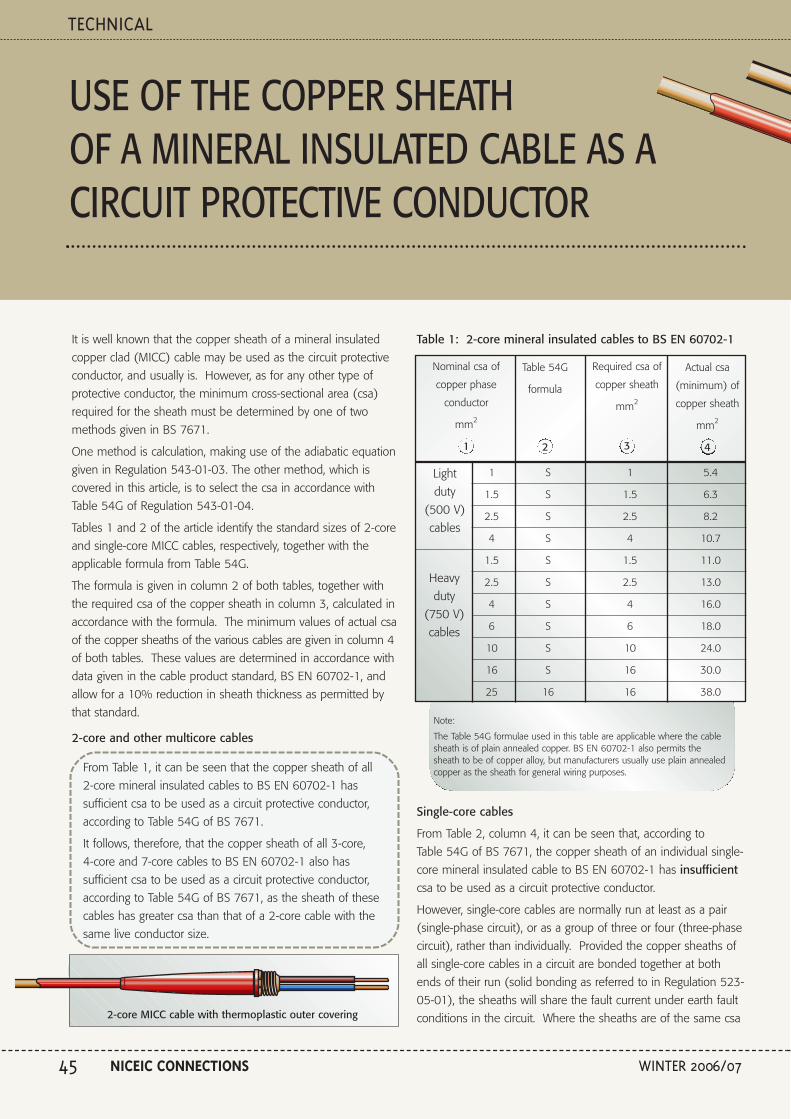
It is well known that the copper sheath of a mineral insulated
copper clad (MICC) cable may be used as the circuit protective
conductor, and usually is. However, as for any other type of
protective conductor, the minimum cross-sectional area (csa)
required for the sheath must be determined by one of two
methods given in BS 7671.
One method is calculation, making use of the adiabatic equation
given in Regulation 543-01-03. The other method, which is
covered in this article, is to select the csa in accordance with
Table 54G of Regulation 543-01-04.
Tables 1 and 2 of the article identify the standard sizes of 2-core
and single-core MICC cables, respectively, together with the
applicable formula from Table 54G.
The formula is given in column 2 of both tables, together with
the required csa of the copper sheath in column 3, calculated in
accordance with the formula. The minimum values of actual csa
of the copper sheaths of the various cables are given in column 4
of both tables. These values are determined in accordance with
data given in the cable product standard, BS EN 60702-1, and
allow for a 10% reduction in sheath thickness as permitted by
that standard.
2-core and other multicore cables
From Table 1, it can be seen that the copper sheath of all
2-core mineral insulated cables to BS EN 60702-1 has
sufficient csa to be used as a circuit protective conductor,
according to Table 54G of BS 7671.
It follows, therefore, that the copper sheath of all 3-core,
4-core and 7-core cables to BS EN 60702-1 also has
sufficient csa to be used as a circuit protective conductor,
according to Table 54G of BS 7671, as the sheath of these
cables has greater csa than that of a 2-core cable with the
same live conductor size.
Table 1: 2-core mineral insulated cables to BS EN 60702-1
Single-core cables
From Table 2, column 4, it can be seen that, according to
Table 54G of BS 7671, the copper sheath of an individual single-
core mineral insulated cable to BS EN 60702-1 has insufficientcsa to be used as a circuit protective conductor.
However, single-core cables are normally run at least as a pair
(single-phase circuit), or as a group of three or four (three-phase
circuit), rather than individually. Provided the copper sheaths of
all single-core cables in a circuit are bonded together at both
ends of their run (solid bonding as referred to in Regulation 523-
05-01), the sheaths will share the fault current under earth fault
conditions in the circuit. Where the sheaths are of the same csa
USE OF THE COPPER SHEATHOF A MINERAL INSULATED CABLE AS ACIRCUIT PROTECTIVE CONDUCTOR
TECHNICAL
NICEIC CONNECTIONS WINTER 2006/0745
2-core MICC cable with thermoplastic outer covering
Nominal csa of
copper phase
conductor
mm2
1
Table 54G
formula
2
Required csa of
copper sheath
mm2
3
Actual csa
(minimum) of
copper sheath
mm2
4
1 S 1 5.4
1.5 S 1.5 6.3
2.5 S 2.5 8.2
4 S 4 10.7
1.5 S 1.5 11.0
2.5 S 2.5 13.0
4 S 4 16.0
6 S 6 18.0
10 S 10 24.0
16 S 16 30.0
25 16 16 38.0
Light
duty
(500 V)
cables
Heavy
duty
(750 V)
cables
Note:
The Table 54G formulae used in this table are applicable where the cablesheath is of plain annealed copper. BS EN 60702-1 also permits thesheath to be of copper alloy, but manufacturers usually use plain annealedcopper as the sheath for general wiring purposes.
sn01079
sn01079
sn01080

as each other, they can be expected to share the fault current
reasonably evenly, and they can be regarded as forming a circuit
protective conductor of a size equal to their total csa.
From Table 2, column 5 it can be seen that, where the
copper sheaths of two single-core cables to BS EN 60702-1
having the same nominal sheath csa as each other are
bonded together at both ends, the two sheaths together
have sufficient csa to be used as a circuit protective
conductor, according to Table 54G of BS 7671.
It follows, therefore, that the combined sheath csa of three or
four single-core cables to BS EN 60702-1 will also be
sufficient for a circuit protective conductor, according to
Table 54G of BS 7671, provided the sheaths are bonded
together at both ends of the cable run.
Notes:
1 Darker shaded areas indicate that the csa is insufficient to meet Table54G requirements.
2 The Table 54G formulae used in this table are applicable where thecable sheath is of plain annealed copper. BS EN 60702-1 alsopermits the sheath to be of copper alloy, but manufacturers usuallyuse plain annealed copper as the sheath for general wiring purposes.
3 The csa values in column 5 apply only where the cable sheaths arebonded together at both ends of their run (solid bonding as referredto in Regulation 523-05-01). This would be the case where, forexample, all terminations include earth tail pots connected to theearthing terminal of the equipment at both ends or glands connectedto a common metallic gland plate at the equipment at both ends.
TECHNICAL
WINTER 2006/07 NICEIC CONNECTIONS 46
Single-core MICC cable with thermoplastic outer covering
Nominal csa ofcopper phase
conductor
mm2
Table 54G
formula
Required csaof copper
sheath
mm2
Actual csa(minimum) ofcopper sheath
mm2
10 S 10 9.0 18.0
16 S 16 12.0 24.0
25 16 25 15.0 30.0
50 S/2 25 22.0 44.0
70 S/2 35 27.0 54.0
95 S/2 47.5 32.0 64.0
120 S/2 60 37.0 74.0
150 S/2 75 44.0 88.0
185 S/2 92.5 54.0 108.0
240 S/2 120 70.0 140.0
Heavy
duty
(750 V)
cables
Table 2: Single-core mineral insulated cables to BS EN 60702-1
1 2 3 4 5
Sheath ofan individual
cable
Combinedsheaths of two
cables(solid bonded)
Protection against indirect contact
Notwithstanding consideration of the thermal constraints, the
contribution that the impedance of the copper sheath makes to
the total earth fault loop impedance (Zs) must also be
considered. In some cases, the impedance of the circuit
protective conductor may impose a constraint on the overall
length of a circuit, in terms of affording protection against indirect
contact.
Use of the copper sheath as a main equipotential bondingconductor
It should be noted that the csa of the copper sheath may not be
sufficient to meet the requirements for a main equipotential
bonding conductor. (For minimum cross-sectional areas required
for main bonding conductors for installations where PME
conditions apply, see Table 54H of BS 7671.
sn01080
sn01079
sn01080
sn01079
sn01080sn01079
sn01080

TECHNICAL
NICEIC CONNECTIONS WINTER 2006/0747
A PRACTICAL GUIDETO EVERYDAY ELECTRICAL PROBLEMS
snags solutions
‘Snags & Solutions’, the NICEIC’s most requested problem
solving book, is available in two volumes covering
commonly encountered electrical installation problems.
Part 1 addresses 50 problems relating to earthing and bonding, whilst
Part 2 covers 55 problems relating to wiring systems (as well as giving
guidance on the application of the new wiring colours). Each book,
available from NICEIC Sales, costs only £15. Other volumes of Snags
and Solutions may be published in due course.
To give an indication of the value of these books, a snag and solution is
being covered in each successive issue of Connections. This issue
addresses a snag from Part 2, relating to cable damage by vermin.
Damage to cables from the gnawing of rats, mice
and squirrels is a relatively common occurrence.
In some locations cables can be susceptible to damage by vermin.
Damage can occur over considerable lengths of cable where
rodents have gnawed away the sheath and insulation, resulting in
exposure of the conductors.
Where exposed conductors are surrounded by rodents’ nesting
materials, which are generally combustible, there is a risk of fire.
There is also a risk of shock to persons from direct contact with an
exposed live conductor.
Evidence shows that rodents are not uniquely attracted to one type
of cable. All types of cable, for example: thermoplastic (pvc), rubber
and lead sheathed cables, seem susceptible to attack.
Cable damage by verminsnag31

TECHNICAL
WINTER 2006/07 NICEIC CONNECTIONS 48
Where cables are installed in areas that are, or are liable to
be, inhabited by rodents, such as might be found in farm
buildings and the roof voids and cellars of certain older
properties, the wiring system must be capable of resisting
damage caused by gnawing. It is advisable, therefore, to
select a wiring system such as one of the following:
• Steel conduit, or trunking
• Mineral-insulated, metal-sheathed cables
• Steel-wire armoured cables
• Thermoplastic (pvc) sheathed cables having galvanized steel
braid covering
• Steel capping to protect short exposed runs of thermoplastic
(pvc) insulated and sheathed cables.
solution
snag 31b
Alternatively, if the use of such wiring systems is impracticable,
cables are less likely to be attacked by rodents if they are
attached as far up a wall as possible, or, where installed in a roof
void, fixed to the underside of the roof structure.
It is worth noting that enclosures of electrical switchgear,
accessories and wiring systems (such as trunking), etc should be
free of any openings through which rodents could enter and build
nests and cause damage to cables.
Manufacturers of cables have said that there is no wholly effective
means of prevention, and that if repellents are incorporated in the
cable sheath they would almost certainly be toxic and therefore
unsuitable for handling in cable factories, and might also be a
danger to people handling the finished cable.
Regulation 522-10-01(Presence of fauna(AL))
Where expected conditions constitute a hazard (AL2), the wiring system
shall be selected accordingly or special protective measures shall be
adopted.

ASSESSING THE GENERAL CHARACTERISTICSOF A DOMESTIC ELECTRICAL INSTALLATION
TECHNICAL
NICEIC CONNECTIONS WINTER 2006/0749
With the exception of the maximum demand, this article gives
guidance on assessing these characteristics for the installation of
an individual dwelling (house or flat).
See the article on page 51 for guidance on assessing the
maximum demand for a dwelling.
General
Regulation 300-01-01 requires the characteristics listed below be
assessed, in accordance with the Chapters indicated. The
regulation also requires the characteristics to be taken into
account in the choice of methods of protection for safety
(Part 4) and selection and erection of equipment for the
installation (Part 5). The characteristics are:
• the purpose of the installation, its structure and its supplies
(Chapter 31)
• the external influences which may affect it (Chapter 32)
• the compatibility of the electrical equipment (Chapter 33)
• Its maintainability (Chapter 34).
Purpose, structure and supplies (Chapter 31)
Chapter 31 identifies particular characteristics relating to the
purpose, structure and supplies of the installation that must be
determined and taken into account. An abbreviated checklist of
these characteristics is given in Table 1 of this article.
Table 1 – Checklist of characteristics relating to purpose,structure and supplies
For either a new installation or an alteration or addition to an existing installation, Part 3 of BS 7671requires an assessment to be made of the general characteristics, including the maximum demand.
a) The maximum demand (see the article on page 51 of
this issue of Connections)
b) The number and type of live conductors
c) The type of earthing arrangement (TN C, TN S, TN C S or TT)
d) The nature of supply, including:
(i) nominal voltage(s)
(ii) nature of current (a.c. or d.c.) and frequency
(iii) prospective short-circuit current at the supply intake
(iv) earth fault loop impedance of the supply to the
intake position (Ze)
(v) suitability of the installation for its required purposes,
including maximum demand
(vi) type and rating of the main protective device
(supply main fuse)
e) The supplies for safety services and standby purposes
f) The arrangement of installation circuits

NEWS
WINTER 2006/07 NICEIC CONNECTIONS 50
Information about the main incoming electricity supply, for thepurpose of items b), c) and d) in Table 1, can be obtained fromthe electricity distributor. Most distributors make this informationavailable by publishing notes of guidance giving:
• the number of phases (generally one for a single dwelling)• the frequency (generally 50 Hz)• the nominal voltage (generally 230 V)• the maximum prospective short circuit current at the supply
terminals• the maximum earth loop impedance of the earth fault path
outside the installation (Ze)• the type and rating of the distributor's protective device or
devices nearest to the supply terminals, and• the type of earthing system applicable to the connection
(TN C, TN S, TN C S or TT).
External influences (Chapter 32)
Part 2 of BS 7671 defines an external influence as ‘Any influenceexternal to an electrical installation which affects the design andsafe operation of that installation.’
The electrical installation designer must assess the externalinfluences to which each part of the installation is likely to beexposed during installation, use and maintenance. The externalinfluences must be taken into account in the choice of methodsof protection for safety and selection and erection of equipmentfor the installation. (Regulation Groups 300-01, 512-06 andSection 522 refer.)
Examples of external influences include ambient temperature,presence of water and high humidity, impact and solar radiation.A comprehensive list of external influences, some of which willapply to the installation in a dwelling, is given in Appendix 5 ofBS 7671.
The bathroom is a part of every dwelling where the presence ofwater and high humidity needs particular consideration. InSection 601 of BS 7671 – Locations Containing a Bath orShower – Regulation 601-06-01 specifies the minimum degreesof protection (IP ratings) for electrical equipment, including wiringsystems, to be installed in each of zones 0, 1, 2 and 3 of thelocation.
Compatibility of the electrical equipment (Chapter 33)
Regulation 331-01-01 requires an assessment to be made of anycharacteristics of the equipment of an installation likely to haveharmful effects on other equipment or services, or be harmfullyaffected by them, or impair the supply. Examples of suchcharacteristics (listed in Regulation 331-01-01) includeovervoltages, undervoltages, harmonic currents, starting currentsand protective conductor currents.
For an installation in a dwelling, the main practical considerationregarding compatibility is to follow the manufacturers’ instructionsin applying and installing equipment.
For example, where lighting is to be controlled by a dimmer, theluminaires must be suitable for this purpose. (Certain types ofluminaire, such as fluorescent and extra-low voltage, requirespecial controlgear to achieve dimming). In addition, the dimmermust be adequately rated for the load current and for the type ofload (resistive or inductive).
Maintainability (Chapter 34)
Regulation 341-01-01 requires an assessment to be made of thefrequency and quality of maintenance that an installation canreasonably be expected to receive during its intended life.
The reason for the assessment is to allow the equipment andprotective measures for the installation to be chosen andinstalled so that:
• periodic inspection, testing, maintenance and repair likely to beneeded can be readily and safely carried out,
• protective measures for safety remain effective, and• the reliability of equipment is sustained.Wherever practicable, the equipment comprising the electricalinstallation in dwelling should be of types requiring little or nomaintenance.
Where maintenance is necessary, the equipment concernedshould be selected and installed to make it as simple and safe aspossible to maintain, especially where it may be worked on bythe householder. For example, luminaires should not bepositioned where it would be difficult to gain access for re-lamping.

ASSESSING THE MAXIMUM DEMAND OFA DOMESTIC ELECTRICAL INSTALLATION
TECHNICAL
NICEIC CONNECTIONS WINTER 2006/0751
Maximum demand is one of the general characteristics of anelectrical installation that Part 3 of BS 7671 requires to beassessed. This article gives guidance on assessing the maximumdemand for the installation of an individual dwelling (house orflat).
Guidance on assessing the other general characteristics for theinstallation of such a dwelling is given in an article on page 49.
Requirement to assess the maximum demand
Regulation 311-01-01 requires the maximum demand of theinstallation, expressed in amperes, to be assessed.
The purpose of the assessment is to establish whether thesupply of electricity to the installation will be of sufficient ratedcurrent for the purpose for which the installation is intended.
Making the assessment
For assessing maximum demand, sufficient information isneeded about the connected load, how the installation is likely tobe used and any diversity factors that may be applied.
Failure to allow for diversity, where applicable, would normallylead to assessing the available supply capacity as inadequate forthe load of the installation. In addition, the economic design ofan installation almost always means that diversity must be takeninto account for certain circuits.
For example, to comply with Regulation 553-01-07, an adequatenumber of suitably positioned socket-outlets are needed forportable electrical equipment. Without allowing for diversity, acircuit having (say) fifteen 13 A socket-outlets would have apotential load of approximately 196 A, which would exceed therated current of the supply normally provided to a domesticinstallation (typically 60 to 100 A).
In fact, the load on the socket-outlet circuits in a dwelling doesnot depend on the number of socket-outlets, but on theparticular items of current-using equipment connected to thesocket-outlets and in use.
A variety of methods exist for estimating the maximum demandfor a distribution system (or distribution circuit) of a dwelling. Themethod adopted will depend on the information available at thetime the estimate is made. For most installations, the estimatewill be approximate as there is no exact method for calculatingmaximum demand in all circumstances. The appropriatediversity factors may be known or can be estimated.
Where the diversity factor for a distribution system of a dwellingis not known, the installation designer may wish to adopt one ofthe following two methods:
• the method described in IEE Guidance Note 1 – Selection andErection, or
• applying a judgmental approach based on engineeringknowledge and experience.
The method described in IEE Guidance Note 1
The method described in IEE Guidance Note 1 uses theinformation in Table H2 of that publication for estimating themaximum demand for the distribution circuit supplying all of thecircuits of an individual household installation. Information fromTable H2 is reproduced in Table 1 of this article for ease ofreference.
Table 1 – Allowance for diversity to be applied to an individual
household installation, including an individual dwelling in a block.
Purpose of final circuitfed from conductors orswitchgear to whichdiversity applies
Lighting
Heating appliances
Cooking appliance(s)
Instantaneous water
heaters (including
electric shower heaters)
Storage water heaters
Floor warming
installations
Socket-outlet and
stationary equipment
supplied by a standard
arrangement
Diversity factor to be applied tothe distribution circuit
66 % of the connected lighting load
The first 10 A of the connected load
plus 50 % of the remainder of the
connected load
The first 10 A of the connected load
plus 30 % of the remainder of the
rated current in excess of 10 A plus
5 A if socket outlet incorporated in
the control panel
100 % full load (F.L.) of the largest
appliance plus 100 % F.L. of the 2nd
largest appliance plus 25 % F.L. of
the remaining appliances
No diversity applied
No diversity applied
100 % of current demand of largest
socket-outlet circuit plus 40 % of
current demand of every other
socket-outlet circuit
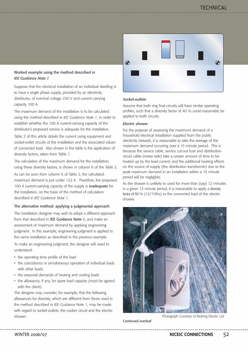
TECHNICAL
WINTER 2006/07 NICEIC CONNECTIONS 52
Worked example using the method described in
IEE Guidance Note 1
Suppose that the electrical installation of an individual dwelling is
to have a single phase supply, provided by an electricity
distributor, of nominal voltage 230 V and current carrying
capacity 100 A.
The maximum demand of the installation is to be calculated
using the method described in IEE Guidance Note 1, in order to
establish whether the 100 A current-carrying capacity of the
distributor’s proposed service is adequate for the installation.
Table 2 of this article details the current using equipment and
socket-outlet circuits of the installation and the associated values
of connected load. Also shown in the table is the application of
diversity factors, taken from Table 1.
The calculation of the maximum demand for the installation,
using these diversity factors, is shown in column 6 of the Table 2.
As can be seen from column 6 of Table 2, the calculated
maximum demand is just under 122 A. Therefore, the proposed
100 A current-carrying capacity of the supply is inadequate for
the installation, on the basis of the method of calculation
described in IEE Guidance Note 1.
The alternative method: applying a judgmental approach
The installation designer may wish to adopt a different approach
from that described in IEE Guidance Note 1, and make an
assessment of maximum demand by applying engineering
judgment. In this example, engineering judgment is applied to
the same installation as described in the previous example.
To make an engineering judgment, the designer will need to
understand:
• the operating time profile of the load
• the coincidence or simultaneous operation of individual loads
with other loads
• the seasonal demands of heating and cooling loads
• the allowance, if any, for spare load capacity (must be agreed
with the client).
The designer may consider, for example, that the following
allowances for diversity, which are different from those used in
the method described in IEE Guidance Note 1, may be made
with regard to socket-outlets, the cooker circuit and the electric
shower:
Socket-outlets
Assume that both ring final circuits will have similar operatingprofiles, such that a diversity factor of 40 % could reasonably beapplied to both circuits.
Electric shower
For the purpose of assessing the maximum demand of ahousehold electrical installation supplied from the publicelectricity network, it is reasonable to take the average of themaximum demand occurring over a 15 minute period. This isbecause the service cable, service cut-out fuse and distributioncircuit cable (meter tails) take a certain amount of time to beheated up by the load current, and the additional heating effectson the source of supply (the distribution transformer) due to thepeak maximum demand in an installation within a 15 minuteperiod will be negligible.
As the shower is unlikely to used for more than (say) 12 minutesin a given 15 minute period, it is reasonable to apply a diversityfactor of 80 % (12/15ths) to the connected load of the electricshower.
N
E E
L
SNAG 27c
Continued overleafPhotograph Courtesy of Redring Electric Ltd

ASSESSING THE MAXIMUM DEMAND OF A DOMESTICELECTRICAL INSTALLATION CONT...
TECHNICAL
NICEIC CONNECTIONS WINTER 2006/0753
The allowances for diversity in this example are for illustrativepurposes only and must be treated with some reservation. Theactual allowances that the installation designer makes must bebased on his own judgment, taking account of the circumstancesapplying to the particular installation.
The calculation of the maximum demand for the installation,taking account of the allowances for diversity described above for
the socket-outlets and electric shower, is given in column 7 ofTable 2.
As can be seen from column 7 of Table 2, the calculatedmaximum demand is just over 88 A. Therefore, the proposed100 A current-carrying capacity of the supply is adequate for theinstallation, on the basis of this alternative method of calculation.
Table 2Calculation of the maximum demand of the installation of anindividual dwelling by applying diversity factors to the connectedloads of the individual final circuits
Description Number of points
servedConnected load
per point
Total connected
load of all points
Allowance for
diversity
(from Table 1)
Calculation to determine the maximum
demand of the installation
Using the method
described in IEE
Guidance Note 1
Using the
alternative
method: applying
a judgmental
approach
1 2 3 4 5 6 7
Mains voltagetungsten halogen
lighting
Mains voltagetungsten halogen
lighting
Cooker(consisting of 4rings, grill and
oven) without asocket-outlet in
the control panel
32 A ring finalsocket-outlet
circuit
32 A ring finalsocket-outlet
circuit
Electric shower(instantaneouswater heater)
Electric shaversocket-outlet
Security alarm
Smoke/heatalarms
6
7
1
8
12
1
1
1
4
100 W
100 W
10 kW
See Note 2.
See Note 2.
10.8 kW
N/A
N/A
N/A
600 W ÷ 230 V =2.61 A
700 W ÷ 230 V =3.04 A
10,000 W ÷ 230 V =43.5 A
32 A
32 A
10,800 W ÷ 230 =47 A
-
-
-
90% of the connectedload
90% of the connectedload
10 A of the connectedload plus 30% of the
remainder of theconnected load
100% of currentdemand of largest
socket-outlet circuit plus40% of current
demand of every othersocket-outlet circuit
No diversity allowed
May be neglected
May be neglected
May be neglected
2.35 A
2.74 A
25.0 A
32.0 A
12.8 A
47.0 A
0 A
0 A
0 A
121.89 A
2.35 A
2.74 A
24.1 A
12.8A
12.8 A
37.6 A
0 A
0 A
0 A
92.39 ATotal for the installation
Notes to Table 2:
1. The diversity factors used in the table do not apply where the source of supply is agenerator, such as a standby diesel-or-petrol-engine-driven generator.
2. The current demand associated with the ring final circuits to which diversity factorsfrom Table 2 should be applied in order to estimate the maximum demand of theinstallation is the nominal current (In) of the circuit protective device.

TECHNICAL
WINTER 2006/07 NICEIC CONNECTIONS 54
Approved Contractors and Domestic Installers
have a responsibility to ensure the reliability
of the test instruments they use to carry out
the range of measurements required by
BS 7671 for certification and reporting
purposes.
They therefore need to have a system
in place which enables them to
confirm the continuing accuracy and
consistency of all such test
instruments, the effectiveness of
which NICEIC Engineers (Area
Engineers and Associates) will
check during their assessment
visits.
Where an Approved Contractor or
Domestic Installer is unable to demonstrate to the
satisfaction of the NICEIC Engineer that an effective management
system for test instruments is in place, the NICEIC Engineer will
record this in the Assessment Report as a non-compliance.
Any successive repetition of such a non-compliance is likely to be
recorded as a major non-compliance which, in most cases, would
warrant a further assessment visit to check that a suitable system
has been put in place.
There are several systems that businesses can use to ensure the
ongoing accuracy and consistency of their test instruments,
including:
• Maintaining records over time of comparative cross-checks with
other test instruments used by the business.
• Maintaining records over time of measurements of the
characteristics of designated reference circuits or devices. For
example, the consistency of continuity, insulation resistance
and earth electrode test instruments could be checked against
a proprietary resistance box or a set of suitable resistors. Earth
fault loop impedance test instruments could be checked by
carrying out tests on a designated socket-outlet (on a non-RCD
protected circuit) in the contractor’s office. RCD test
instruments could be checked by carrying out tests on an RCD
unit plugged into the designated socket-outlet.
Either of these systems would provide a
measure of confidence in the
consistency of test measurements over
time. However, before any reliance
could be placed on them, the accuracy
of each test instrument would first
need to be confirmed, such as by
formal calibration/re-calibration
supported by calibration certificates
issued by recognized organisations, with
measurements traceable to national
standards. It should be noted that new or
repaired test instruments may not be supplied
with calibration certificates unless specifically
requested.
Another alternative would simply be to
maintain records of the formal calibration/
re-calibration of test instruments at the intervals recommended
by the instrument manufacturers, supported by calibration
certificates. However, given the arduous conditions in which test
instruments often have to be used, such a system would not
provide any assurance of continuing accuracy and consistency
over the period between the formal calibration checks.
NICEIC therefore prefers the use of systems and records based
on the initial confirmation of the accuracy of test instruments by
means of calibration certificates, coupled with suitable cross-
checks or comparative measurements over time to confirm
ongoing consistency. (See the article on page 25 regarding the
new NICEIC instrument check box).
Each test instrument used by the business must be clearly and
uniquely identified for record and traceability purposes, for
example by a serial number.
ACCURACY AND CONSISTENCY OFTEST INSTRUMENTS
An example of a test
instrument accuracy
record can be
downloaded from the
NICEIC website.

TECHNICAL
NICEIC CONNECTIONS WINTER 2006/0755
Where the steel wire armouring of a cable is to be used as acircuit protective conductor, then, as for any other type ofconductor used for this purpose, the minimum cross-sectionalarea (csa) required must be determined by one of two methodsgiven in BS 7671. One of the methods, which was covered inan article in Connections issue 152 (Winter 2004/05), is toselect the csa in accordance with Table 54G of Regulation543-01-04.
The other method (covered in this article) is by calculation,making use of the adiabatic equation given in Regulation 543-01-03:
This article shows how to use the adiabatic equation graphically,which in many cases is a convenient method of applying it.
Where the adiabatic equation is used (either graphically orotherwise), it will often be found that the armouring of a cablehas sufficient csa for use as the circuit protective conductor, eventhough Table 54G indicates that the csa is not sufficient.
Using the adiabatic equation graphically
The adiabatic equation for a circuit protective conductorcan be plotted onto the same log/log graph paper asthe time/current characteristic of the associatedovercurrent protective device. The result is a straight line calledan adiabatic line, examples of which are shown in Figures 1 and2 of this article.
The simplest way to obtain the adiabatic line for a conductor of S mm2 and
a given value of k is first to plot along the horizontal line for0.1 seconds, the point corresponding to 3.162 kS amperes *.Then along the horizontal line for 1 second, plot the pointcorresponding to kS amperes. Join the two points and extendthe line to the horizontal line corresponding to 5 seconds.
The adiabatic lines may be plotted onto the timecurrent/characteristics from Appendix 3 of BS 7671, as is done inFigures 1 and 2. Alternatively, the lines may be plotted onto thetime/current characteristics published by the manufacturer of theparticular protective device being installed. Manufacturers’time/current characteristics must be used for devices whosecharacteristics are not given in Appendix 3 of BS 7671, such asMCCBs (moulded-case circuit-breakers) and BS 88 fuses withratings above 200 A.
Where the protective device is a fuse
Figure 1 gives an example of adiabatic lines for cable armouringplotted onto the time/current characteristics of fuses, in this casethe fuses being to BS 88-2.1 and BS 88-6.
S= mm 2
kI 2t
In fact, according to the adiabatic equation, the armouring of all
multicore thermosetting insulated cables to BS 5467: 1997
and BS 6724: 1997, and all multicore PVC insulated cables
to BS 6346: 1997, have sufficient csa for use as the circuit
protective conductor, provided that:
• the cable is protected against overload in accordance with
BS 7671 by a protective device complying with the
characteristics given in Appendix 3 of that standard, and
• the earth fault loop impedance (Zs) at the far end of the
circuit does not exceed the limiting value given in
BS 7671 in order for automatic disconnection in the
event of an earth fault to occur within:
• 5 s, where the protective device is a fuse, or
• 0.1 s (‘instantaneously’) where the protective device is
a circuit-breaker.
Tim
e se
con
ds
Prospective current, r.m.s. amperes
10 000
1 000
100
10
1
0.1
0.011 10 100 1 000 10 000
6 A 20 A 32 A 50 A 80 A 125 A 200 A
5 s
6 pt6 pt6 pt6 pt6 pt6 pt
sn00953
Time/current characteristics for fuses to BS 88-2,1 and BS 88-6
FuseRating
6 A
20 A
32 A
50 A
80 A
125 A
200 A
Current for time
0.1 sec
36 A
175 A
320 A
540 A
1100 A
1800 A
3000 A
0.2 sec
31 A
150 A
260 A
450 A
890 A
1500 A
2500 A
0.4 sec
27 A
130 A
220 A
380 A
740 A
1300 A
2200 A
5 secs
17 A
79 A
125 A
220 A
400 A
690 A
1200 A
35 mm 2
16/25 mm 2
6 mm 2
1.5 mm 2
Adiabatic lines for the armouring of various sizes of 2-core thermosettinginsulated cables to BS 5467 or BS 6724, superimposed onto BS 88 fusecharacteristics
Fig 1
Note: The value of k used to plot the adiabatic lines in Figure 1 is 46, obtainedfrom Table 54D of BS 7671. The values of S (the csa of the armouring)used to plot the lines were taken from BS 5467 or BS 6724.
USE OF STEEL WIRE ARMOURING AS A CIRCUITPROTECTIVE CONDUCTOR- DETERMINING THEREQUIRED CSA BY CALCULATION
* The reason why 3.162 kS amperes is used in relation to a time of 0.1 s is that 3.162 kS is equalto kS divided by the square root of 0.1 (obtained by transposing the adiabatic equation into theform I = kS/ t).

TECHNICAL
WINTER 2006/07 NICEIC CONNECTIONS 56
It can readily be established from Figure 1 whether the armouringof a given size of two core cable has sufficient csa for use as thecircuit protective conductor, if protected by a given rating ofBS 88 fuse, and at a given disconnection time. Considering thepoint where the adiabatic line for the armouring of the relevantsize of cable crosses the horizontal line for 5 s (or shorterdisconnection time where applicable), then if the time/currentcharacteristic of the relevant rating of fuse lies to the left of thispoint, the csa of the armouring is sufficient to satisfy the adiabaticequation.
For example, it will be seen from Figure 1 that, at a disconnectiontime of 5 s, the armouring of a 2-core 16 mm2 or 25 mm2 cableto BS 5467 or BS 6724 is sufficient for use as the circuitprotective conductor if the protective device is a 125 A BS 88fuse, but not if it is a 200 A fuse. However, for the same size ofcable but with a 0.4 s disconnection time, Figure 1 shows thatthe armouring has sufficient csa for use as the circuit protectiveconductor, even if the fuse rating is 200 A.
Applying adiabatic lines to all the fuse time/current characteristicsin Appendix 3 of BS 7671, Table 1 shows the maximumacceptable fuse current ratings for various sizes of 2-corethermosetting insulated steel wire armoured cable to BS 5467 orBS 6724, at a disconnection time of 5 s, in order for thearmouring to be of sufficient csa for use as the circuit protectiveconductor.
Table 1: Maximum fuse rating in order for the armouring of cablesto BS 5467 or BS 6724 to be of sufficient csa for use as the circuitprotective conductor (at 5 s disconnection time)
The fuse ratings in Table 1 are, in some cases, too high to affordoverload protection to the live conductors. Where the fuse rating
is low enough to afford overload protection to the liveconductors, and provided the earth fault loop impedance (Zs)corresponds to a disconnection time not exceeding 5 s † , it willalways be found that the armouring has sufficient csa for use asthe circuit protective conductor. This is true for all multicorearmoured cables with two or more cores to BS 5467, BS 6724 orBS 6346, where the fuse complies with the characteristics givenin Appendix 3 of BS 7671.
Where the protective device is a circuit-breaker
For circuit-breakers, a slightly different approach is required to thatdescribed above for fuses, due to the shape of the time/currentcharacteristic. The characteristic of a circuit-breaker usuallyincludes a vertical portion, where disconnection occurs‘instantaneously’, ie within 0.1 s.
Figure 2 (overleaf) gives an example of adiabatic lines for cablearmouring plotted onto the time/current characteristics ofcircuit-breakers, in this case the circuit-breakers being Type D toBS EN 60898.
From Figure 2, it can be established whether the armouring of agiven size of two-core cable has sufficient csa for use as thecircuit protective conductor, if protected by a given current ratingof Type D circuit-breaker to BS EN 60898. Considering the pointwhere the adiabatic line for the armouring of the relevant size ofcable meets the horizontal corresponding to 0.1 s, then if thetime/current characteristic of the relevant rating of circuit-breakerlies to the left of this point, the armouring has sufficient csa foruse as the circuit protective conductor.
For example, it will be seen from Figure 2 that the armouring of a2-core 1.5 mm2 cable to BS 5467 or BS 6724 has sufficient csafor use as the circuit protective conductor if the cable is protectedagainst overload by a 100 A Type D circuit-breaker, but not ifprotected by a 125 A Type D circuit-breaker.
Applying adiabatic lines to all the circuit-breaker time/currentcharacteristics in Appendix 3 of BS 7671, Table 2 (overleaf)shows the maximum acceptable circuit-breaker current ratings forvarious sizes of 2-core thermosetting insulated steel wirearmoured cable to BS 5467 or BS 6724, in order for thearmouring to be of sufficient csa for use as the protectiveconductor.
The circuit-breaker current ratings in Table 2 are, in some cases,too high to afford overload protection to the live conductors.Where the circuit-breaker rating is low enough to afford suchprotection, and provided the earth fault loop impedance (Zs) issufficiently low for the circuit-breaker to operate instantaneously(within 0.1 s) under earth fault conditions, it will always be foundthat the armouring has sufficient csa for use as the circuitprotective conductor. This is true for all multicore armouredcables, with two or more cores, to BS 5467, BS 6724 orBS 6346, where the circuit-breaker complies with thecharacteristics given in Appendix 3 of BS 7671.
Protection against indirect contact
Notwithstanding consideration of the thermal constraints (dealtwith above), the contribution that the impedance of the cablearmouring makes to the total earth fault loop impedance (Zs)must also be considered. In some cases, the impedance of the
1.5 15 60 A 45 A 63 A
2.5 17
4.0 19 60 A
6.0 22 100A 80 A
10.0 26 80 A
16.0 42 100 A 125 A
25.0 42
35.0 60 200 A
50.0 68
70.0 80
95.0 113
120.0 125
150.0 138
185.0 191
240.0 215
300.0 235
No larger
fuses are
available No larger
fuses are
available
Consult fuse
manufacturer’s
data (no data
for larger fuses
is given in
Appendix 3 of
BS 7671)
BS 1361 BS 88
Armour csafor 2-core
cablemm 2
Cable liveconductor
csamm 2
BS 3036
Maximum fuse current rating

TECHNICAL
NICEIC CONNECTIONS WINTER 2006/0757
circuit protective conductor may impose a constraint on theoverall length of a circuit, in terms of affording protectionagainst indirect contact.
Use of armouring as a main equipotential bondingconductor
It should be noted that the csa of the cable armouring may notbe sufficient to meet the requirements for a main equipotentialbonding conductor. (For minimum cross-sectional areasrequired for main bonding conductors for installations wherePME conditions apply, see Table 54H of BS 7671.)
Tim
e se
con
ds
Prospective current, r.m.s. amperes
10 000
1 000
100
10
1
0.1
0.01
For prospective fault currents in excessof those providing instantaneous operationrefer to the manufacturer’s let-through energy data
1 10 100 1 000 10 000
6 A
10 A
16 A
20 A
25 A
32 A
40 A
50 A
63 A
80 A
100
A12
5 A
4.0 2.5
1.5
5 s
Time/current characteristics for Type Dcircuit-breakers to BS EN 60898
and RCBOs to BS EN 61009
Current for time, 0.1 to 5 secs
Rating
6 A
10 A
16 A
20 A
25 A
32 A
40 A
50 A
63 A
80 A
100 A
125 A
Current
120 A
200 A
320 A
400 A
500 A
640 A
800 A
1000 A
1260 A
1600 A
2000 A
25000 A
sn00952
Fig 2
Notes: 1) The value of k used to plot the adiabatic lines in Figure 2 is 46, obtained from Table 54Dof BS 7671. The values of S (the csa of the armouring) used to plot the lines were takenfrom BS 5467 or BS 6724.
2) Type D circuit-breakers have been chosen for the example in Figure 2 because thecurrent required to cause a Type D circuit-breaker of a given current rating to operateinstantaneously (within 0.1 s) is greater than for circuit-breakers of Type B or Type C, and thethermal effects on the armouring are therefore more onerous.
Adiabatic lines for the armouring of varioussizes of 2-core thermosetting insulated cables toBS 5467 or BS 6724, superimposed ontoBS EN 60898 Type D circuit-breakercharacteristics
continued
Table 2 (opposite): Maximum BS EN 60898 circuit-breaker rating
in order for the armouring of cables to BS 5467 or BS 6724 to be
of sufficient csa for use as the protective conductor
1.5 15 125 A 125 A 100 A
2.5 17
4.0 19 125 A
6.0 22
10.0 26
16.0 42
25.0 42
35.0 60
50.0 68
70.0 80
95.0 113
120.0 125
150.0 138
185.0 191
240.0 215
300.0 235
Type C Type D
Armour csafor 2-core
cablemm 2
Cable liveconductor
csamm 2
Type B
Maximum circuit-breakercurrent rating
† A disconnection time shorter than 5 s is required by BS 7671 for certain circuits, for reasonsof protection against indirect contact. For example, for a final circuit supplying socket-outletsat a nominal voltage of 230 V, a disconnection time not exceeding 0.4 s is required(Regulation 413-02-09 refers).