is 9122 (2008): inspection gauges for checking type 2 ...b) introduction of segment gauging system...
TRANSCRIPT

Disclosure to Promote the Right To Information
Whereas the Parliament of India has set out to provide a practical regime of right to information for citizens to secure access to information under the control of public authorities, in order to promote transparency and accountability in the working of every public authority, and whereas the attached publication of the Bureau of Indian Standards is of particular interest to the public, particularly disadvantaged communities and those engaged in the pursuit of education and knowledge, the attached public safety standard is made available to promote the timely dissemination of this information in an accurate manner to the public.
इंटरनेट मानक
“!ान $ एक न' भारत का +नम-ण”Satyanarayan Gangaram Pitroda
“Invent a New India Using Knowledge”
“प0रा1 को छोड न' 5 तरफ”Jawaharlal Nehru
“Step Out From the Old to the New”
“जान1 का अ+धकार, जी1 का अ+धकार”Mazdoor Kisan Shakti Sangathan
“The Right to Information, The Right to Live”
“!ान एक ऐसा खजाना > जो कभी च0राया नहB जा सकता है”Bhartṛhari—Nītiśatakam
“Knowledge is such a treasure which cannot be stolen”
“Invent a New India Using Knowledge”
है”ह”ह
IS 9122 (2008): Inspection Gauges for Checking Type 2 TaperThreads of Gas Cylinder Valves, Taper 3 in 25 [MED 16:Mechanical Engineering]


IS 9122 : 2008
Indian Standard INSPECTION GAUGES FOR CHECKING TYPE 2 TAPER
THREAD OF GAS CYLINDER VALVES, TAPER 3 IN 25 — SPECIFICATION
( First Revision )
ICS 17.040.01:23.020.30
© BIS 2008
B U R E A U O F I N D I A N S T A N D A R D S MANAK BHAVAN, 9 BAHADUR SHAH ZAFAR MARG
NEW DELHI 110002
June 2008 Price Group 7

Gas Cylinders Sectional Committee, MED 16
FOREWORD
This Indian Standard (First Revision) was adopted by the Bureau of Indian Standards, after the draft finalized by the Gas Cylinders Sectional Committee had been approved by the Mechanical Engineering Division Council.
This standard was first published in 1979. In this revision changes have been incorporated in the light of the experience gained by the industry and consumers over the years. In this revision following important changes have been made:
a) Inclusion of alternative system for gauging/checking. b) Introduction of segment gauging system for checking form of thread. c) Introduction of master check plug (MCP) for checking wear of ring gauge. d) Introduction of checking method and its acceptance/rejection criteria. e) Introduction of dimension of both large and small end.
Assistance has been taken from the following International Standards:
ISO 10920 : 1997 Gas cylinders — 25E taper thread for connection of valves to gas cylinders — Specification
ISO 11116-1 : 1999 Gas cylinders — 17E taper thread for connection of valves to gas cylinders — Part 1 Specification
ISO 11116-2 : 1999 Gas cylinders — 17E taper thread for connection of valves to gas cylinders — Part 2 Inspection gauges
ISO 11191 : 1997 Gas cylinders — 25E taper thread for connection of valves to gas cylinders — Inspection gauges
Annex B draws attention to the limitations of gauging system specified.
The composition of the Committee responsible for the formulation of this standard is given in Annex C.
For the purpose of deciding whether a particular requirement of this standard is complied with, the final value, observed or calculated, expressing the result of a test or analysis, shall be rounded off in accordance with IS 2 : 1960 'Rules for rounding off numerical values (revised)'. The number of significant places retained in the rounded off value should be the same as that of the specified value in this standard.

IS 9122 : 2008
Indian Standard INSPECTION GAUGES FOR CHECKING TYPE 2 TAPER
THREAD OF GAS CYLINDER VALVES, TAPER 3 IN 25 — SPECIFICATION
( First Revision ) 1 SCOPE
This standard prescribes dimensions, tolerances and material requirements of inspection gauges recommended for checking the taper thread on the valve stems and the threads in the cylinder necks of valve fitting conforming to Type 2 of IS 3224 and Type 2 of IS 8737.
2 REFERENCES
The following standards contain provisions which, through reference in this text constitute provisions of this standard. At the time of publication, the editions indicated were valid. All standards are subject to revision and parties to agreements based on this standard are encouraged to investigate the possibility of applying the most recent editions of the standards indicated below:
IS No.
1570 (Part 2) : 1979
3224 : 2002
8737 : 1995
Title
Schedules for wrought steels : Part 2 Carbon steels (Unalloyed steels) (first revision) Valve fittings for compressed gas cylinders excluding liquefied petroleum gas (LPG) cylinders — Specification (third revision) Valve fittings for use with liquefied petroleum gas (LPG) cylinders of more than 5-litre water capacity — Specification (first revision)
3 DEFINITIONS
For the purpose of this standard, the following definitions shall apply.
3.1 Check Gauge — Gauge for checking dimensional conformity of inspection ring gauges. This gauge is not used for gauging cylinder neck threads.
3.2 Inspection Gauge — Gauge used for the routine gauging of cylinder neck and valve stem thread but not for checking other gauges.
3.3 Single-Part Gauge — Gauge of sufficient length to contact the full length of taper thread. These gauges are plug or ring, plain or threaded.
3.4 Two-Part Gauges — Two separate inspection gauges, used in combination, where one is used to contact the large end of the taper cone and the other small end. These sets of gauges are plug or ring, plain or threaded.
4 DIMENSIONS OF THREADS ON VALVE STEMS AND IN CYLINDER NECKS
4.1 Principal Dimension
Thread reference planes and diameters shown in Fig. 1. Principal dimensions and limits on principal dimensions of valve stem threads and threads in cylinder neck are given in Table 1 and Table 2 respectively.
4.2 Thread Profile
The thread profiles of threaded inspection and check gauges shall be as shown in Fig. 2.
5 GENERAL REQUIREMENTS
5.1 Material
All gauges shall be manufactured from material of suitable strength, stability and hardness.
Example:
85C6/15C4 of IS 1570 (Part 2) or suitable case hardening steel.
5.2 Taper
Taper : 3/25
Taper angle: 6°52'
Taper slope: 12 percent
5.3 Thread Rotation
The thread shall be right handed, such that it moves away from an observer, when rotated clockwise.
5.4 Pitch
The pitch is 1.814 mm (derived from 25.4/14 mm) (see Fig. 2).
1

IS 9122 : 2008
FIG. 1 THREAD REFERENCE PLANES AND DIAMETERS
Table 1 Valve Stem Dimensions (Clause 4.1)
All dimensions in millimetres.
Valve Stem
(1)
Dimension
Tolerance
Nominal Diameter''
(2)
19.8 28.8 +0.12 0
Major Dia at Small End
dle.
(3)
17.28 25.68 +0.12 0
Pitch Dia at Small End
d1p
(4)
16.118 24.518 +0.12 0
Minor Dia at Small End
d1i
(5)
14.956 23.356 +0.12 0
Pitch Dia at Larger End
d2p
(6)
18.638 27.638 +0,12 0
Reference Length
l1
(7)
21 26 —
Full Thread Length l2
(8)
≥ 21 ≥ 26 —
1) Represents the minimum major diameter at the large end of the valve stem.
2

IS 9122 : 2008
Table 2 Cylinder Neck Thread Dimensions (Clause 4.1)
All dimensions in millimetres.
Cylinder Neck Thread
(1)
Dimension
Tolerance
Nominal Diameter
(2)
19.8 28.8 0 –0.12
Major Dia at Small End
D1e
(3)
17.61 25.16 0 00.12
Pitch Dia at Small End D1p
(4)
15.998 23.998 0 –0.12
Minor Dia at Small End
D1i
(5)
14.834 22.836 0 –0.12
Pitch Dia at Larger End
D2p
(6)
18.038 26.638 0 –0.12
Reference Length L1
(7)
17 22 —
Full Thread Length L2
(8)
≥ 17 ≥ 22 —
FIG. 2 THREAD PROFILE
3

IS 9122 : 2008
5.5 Thread Profile
The thread profile is a standard whit worth form, with a 55° angle. The form and thread height measurements are perpendicular to the cone surface (see Fig. 2).
5.6 Hardness
Minimum 750 HV (60 - 62 RC) or its equivalent.
5.7 Finish
Ground lapped and suitably stabilized.
6 GAUGE DIMENSION
The following dimensional requirements apply to gauges shown in Fig. 3 to Fig. 16.
6.1 All dimensions are in millimetres.
6.2 Tolerances for specified dimensions on all gauges are:
a) ±0.01 mm on all lengths, b) ±0.01 mm on diameters of inspection gauges,
and c) –0.01 mm on diameters of check gauges.
–0.02 mm 6.3 For threaded gauges, pitch diameters only are specified. For minor and major diameters (see Fig. 2).
6.4 Unspecified dimension shall be chosen by the manufacturer of the gauges.
7 INSPECTION GAUGES
7.1 Gauge for Cylinder Neck Thread
Dimensions of gauge for cylinder neck thread are given in Table 3. Sample calculation for larger end diameter of 25E thread type is given in Annex A.
7.1.1 Single-Part Plug Gauges
7.1.2 Two-Part Plug Gauges (Small End Diameter)
7.1.3 Two-Part Plug Gauges (Large End Diameter)
7.2 Gauges for Valve Stem Thread
Dimension of limit ring gauges for valve stem thread are given in Table 4. Sample calculation for larger end diameter of 25E thread type is given in Annex A.
7.2.1 Single-Part Ring Gauges
7.2.2 Two-Part Ring Gauges (Small End Diameter)
7.2.3 Two-Part Ring Gauges (Large End Diameter)
7.3 Reference Wear Check Gauges (M)
Dimension for check gauges are given in Table 5. Sample calculation for larger end diameter of 25E thread type is given in Annex A.
8 USE OF INSPECTION GAUGES
8.1 Plain Gauges
Plain gauges shall be lightly pressed into position or over the thread being gauged.
8.2 Threaded Gauges
Threaded gauges shall be screwed into or over the thread being gauged. Undue force shall not be used.
8.3 Accept or Reject Criteria, Using Plug Gauges
Thread acceptability to gauge is determined by the position of the plane at the mouth of the cylinder neck relative to the test surface of the gauge.
The thread shall be considered acceptable to the gauge if this plane is flush with or falls between the test surfaces of the gauge when the gauge is fitted to the thread (see Fig. 17 and Fig. 18).
8.4 Accept or Reject Criteria, Using Ring Gauges
Thread acceptability to gauge is determined by the position of the plane at the flat small end of the stem cone base relative to the test surface of the gauge.
The thread shall be considered acceptable, to the gauge,
Table 3 Dimension for Limit Plug Gauges (Clause 7.1)
Thread Type
(1)
Sizel 17E
Size 2 25E
Neck Size
(2)
W19.8 × 1/14 taper
W28.8 × 1/14 taper
Plain Limit Plug Gauge
d4
(3)
16.876
25.476
d5
(4)
14.836
22.836
Threaded Limit Plug Gauges
Large End Diameter
Major diameter
d6
(5)
18.87
27.47
Pitch diameter
d7
(6)
18.038
26.638
Minor diameter d8, Max
(7)
16.826
25.426
Small End Diameter
Major diameter
d9
(8)
16.83
24.83
Pitch diameter
d10
(9)
15.998
23.998
Minor diameter d11, Max
(10)
14.786
22.786
L
(11)
17
22
4

IS 9122 : 2008
Table 4 Dimensions for Limit Ring Gauges (Clause 7.2)
Thread Type
(1)
Sizel 17E
Size 2 25E
Valve Size
(2)
W19.8 × 1/14 taper
W28.8 × 1/14 taper
Plain Limit Ring Gauge
D4
(3)
19.80
28.80
D5
(4)
17.28
25.68
Threaded Ring Gauges
Large End Diameter
Major diameter D6, Min
(5)
19.85
28.85
Pitch diameter
D7
(6)
18.638
27.638
Minor diameter
D8
(7)
17.806
26.806
Small End Diameter
Major diameter D9, Min
(8)
17.33
25.73
Pitch diameter
D10
(9)
16.118
24.518
Minor diameter
D11
(10)
15.286
23.686
L
(11)
21
26
Table 5 Dimensions for Check Gauges (Clause 7.3)
Thread Type
(1)
Size 1 I7E
Size 2 25E
Valve Size
(2)
W19.8 × 1/14 taper
W28.8 × 1/14 taper
Reference Plug Gauge 'M-1'
d13
(3)
19.80
28.80
d14
(4)
17.40
25.80
Threaded Check Gauges 'M-2'
Large End Diameter
Major diameter
(5)
19.47
28.47
Pitch diameter
(6)
18.638
27.638
Minor diameter d17, Max
(7)
17.426
26.426
Small End Diameter
Major diameter
d18
(8)
17.07
25.47
Pitch diameter
d19
(9)
16.238
24.638
Minor diameter d20, Max
(10)
15.026
23.426
L1
(11)
20
25
FIG. 3 PLAIN PLUG GAUGE FOR MINOR DIAMETER (I-1)
FIG. 4 THREADED PLUG GAUGE FOR PITCH DIAMETER (I-2)
5

IS 9122 : 2008
FIG. 5 PLAIN PLUG GAUGE FOR MINOR DIAMETER
(I-3)
FIG. 6 THREADED PLUG GAUGE FOR PITCH DIAMETER (I-4)
FIG. 7 PLAIN PLUG GAUGE FOR MINOR DIAMETER (I-5)
FIG. 8 THREADED PLUG GAUGE FOR PITCH DIAMETER (I-6)
FIG. 9 PLAIN RING GAUGE FOR MAJOR DIAMETER (I-7)
FIG. 10 THREADED RING GAUGE FOR PITCH DIAMETER (I-8)
6

IS 9122 : 2008
FIG. 11 PLAIN RING GAUGE FOR MAJOR DIAMETER (I-9)
FIG. 12 THREADED RING GAUGE FOR PITCH DIAMETER (I-10)
FIG. 13 PLAIN RING GAUGE FOR MAJOR DIAMETER (I-11)
FIG. 14 THREADED RING GAUGE FOR PITCH DIAMETER (I-12)
FIG. 15 PLAIN CHECK GAUGE ( M - 1 ) FIG. 16 THREADED CHECK GUAGE ( M - 2 )
7

IS 9122 : 2008
FIG. 17 USE OF SINGLE-PART PLUG GAUGE
FIG. 18 USE OF TWO-PART PLUG GAUGE
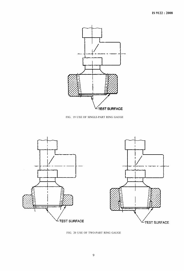
if this plane is flush with or falls between the test surfaces of the gauge when the gauge is fitted to the thread (see Fig. 19 and Fig. 20).
9 VERIFICATION OF INSPECTION GAUGES
9.1 General
During use, inspection gauges will wear and can be damaged. The user shall ensure that the gauges are checked regularly to affirm that they remain within the specific dimensions. Frequency of checks required will depend upon usage and shall be the responsibility of the user.
9.2 Plug Gauges
Verification of inspection plug gauges shall be carried out directly, using optical or other suitable equipment.
9.3 Ring Gauges
Verification of inspection ring gauges cannot be carried out directly, two check plug gauges as shown in Fig. 15 and Fig. 16 shall be used.
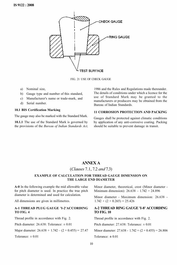
9.4 Use of Check Gauges
The plain check plug gauge shall be placed into the plain inspection ring gauges and the thread check plug gauge shall be screwed into the threaded inspection ring gauge. The inner stepped surface of the inspection ring gauge test surface shall be flush with, or within either of the two test surfaces of the check gauge (see Fig. 21). Undue force shall not be used.
10 MARKING
The gauge shall be marked with the following:
8
IS 9122 : 2008
FIG. 19 USE OF SINGLE-PART RING GAUGE
FIG. 20 USE OF TWO-PART RING GAUGE
9
IS 9122 : 2008
FIG. 21 USE OF CHECK GAUGE
a) Nominal size, b) Gauge type and number of this standard, c) Manufacturer's name or trade-mark, and d) Serial number.
10.1 BIS Certification Marking
The gauge may also be marked with the Standard Mark.
10.1.1 The use of the Standard Mark is governed by the provisions of the Bureau of Indian Standards Act,
1986 and the Rules and Regulations made thereunder. The details of conditions under which a licence for the use of Standard Mark may be granted to the manufacturers or producers may be obtained from the Bureau of Indian Standards.
11 CORROSION PROTECTION AND PACKING
Gauges shall be protected against climatic conditions by application of any anti-corrosive coating. Packing should be suitable to prevent damage in transit.
ANNEX A (Clauses 7.1, 7.2 and 7.3)
EXAMPLE OF CALCULATION FOR THREAD GAUGE DIMENSION ON THE LARGE END DIAMETER
A-0 In the following example the mid allowable value for pitch diameter is used. In practice the true pitch diameter is determined and used for calculation.
All dimensions are given in millimetres.
A-1 THREAD PLUG GAUGE 'I-2'ACCORDING TO FIG. 4
Thread profile in accordance with Fig. 2.
Pitch diameter: 26.638: Tolerance: ± 0.01
Major diameter: 26.638 + 1.742 – (2 × 0.455) = 27.47
Tolerance: ± 0.01
Minor diameter, theoretical, crest (Minor diameter -Minimum dimension): 26.638 – 1.742 = 24.896
Minor diameter - Maximum dimension: 26.638 -1.742 + (2 × 0.265) = 25.426
A-2 THREAD RING GAUGE 'I-8' ACCORDING TO FIG. 10 Thread profile in accordance with Fig. 2.
Pitch diameter: 27.638: Tolerance: ± 0.01
Minor diameter: 27.638 - 1.742 + (2 × 0.455) = 26.806
Tolerance: ± 0.01
10

IS 9122 : 2008
Major diameter, theoretical, crest (Major diameter -Maximum dimension): 27.638 + 1.742 = 29.38
Major diameter- Minimum dimension: 27.638 + 1.742 – (2 × 0.265) = 28.85
A-3 THREAD CHECK GAUGE 'M-2' ACCORDING TO FIG. 16
Thread profile in accordance with Fig. 2.
Pitch diameter: 27.638: Torelance:
Major diameter: 27.638 + 1.742 - (2 × 0.455) = 28.47 Torelance:
Minor diameter, theoretical, crest (Minor diameter -Minimum dimension): 27.638 - 1.742 = 25.896 Minor diameter - Maximum dimension: 27.638 -1.742 + (2 × 0.265) = 26.426
ANNEX B ( Foreword ) LIMITATIONS OF GAUGING SYSTEM
B-1 The purpose of this annex is to draw attention to the limitation of the gauging system specified in this standard.
Taper threads are more difficult to gauge than parallel threads. It is not practical to provide a gauging system which will gauge all aspects of a taper thread.
The gauging system specified in this standard is considered the minimum practical gauging to verify dimensions of a taper thread.
The following aspects of taper threads are amongst those not checked by gauges to this standard:
a) Out of tolerance on minor diameter on the stem,
b) Out of tolerance on major diameter on the neck,
c) Ovality on threads,
d) Die withdrawal lines, e) Surface finish, and f) 'Waisting' of the taper form.
Any of the above could cause difficulties in achieving a gas-tight seal in service.
If difficulties are experienced in service, it is recommended that additional gauging and/or inspection techniques are used to investigate the above aspects. Optical visual techniques can often be used.
Another useful inspection technique which can be applied to stem thread is to modify a pair of single-part ring gauges (see 7.2.1), by removing a 90° segment, allows visual examination of the thread for mating with the gauge and is effective in highlighting 'waisting' or other errors in the taper form. Examples of this type of gauge are given in Fig. 22.
CORRECT FORM 'WAISTING' OF THREADS
FIG. 22 EXAMPLE OF SINGLE-PART RING GAUGE WITH 90° SEGMENT REMOVED
11

IS 9122 : 2008
ANNEX C (Foreword)
COMMITTEE COMPOSITION
Gas Cylinders Sectional Committee, MED 16
Organization
Petroleum and Explosives Safety Organization (PESO), Nagpur
All India Industrial Gases Manufacturers Association, New Delhi
Balmer Lawrie and Co Ltd, Kolkata
Bharat Petroleum Corporation Ltd, Mumbai
Bharal Pumps and Compressors Ltd, Allahabad
BOC India Ltd, Kolkata
Everest Kanto Cylinder Ltd, Aurangabad
Everest Kanto Cylinder Ltd, Tarapur
Hindustan Petroleum Corporation Ltd, Mumbai
Indian Oil Corporation Ltd, Mumbai
International Industrial Gases Ltd, Kolkata
Jagadamba Engineering Pvt Ltd, Secunderabad
J.R. Fabricators Ltd, Mumbai
Kabsons Gas Equipments Ltd, Hyderabad
Kosan Industries Ltd, Mumbai/Surat
LPG Equipment Research Centre, Bangalore
Maruti Koatsu Cylinders Ltd, Mumbai
Met Lab Services Pvt Ltd, Mumbai
Ministry of Defence (DGQA), Pune
Praxair India Pvt Ltd, Bangalore
Research & Development Establishment (Engineers), Pune
Sakha Engineers Pvt Ltd, New Delhi
Siegil India Ltd, Chennai
Steel Authority of India Ltd, Salem/Delhi
Supreme Cylinders Ltd, Delhi
Representative(s)
SHRI M . ANBUNATHAN (Chairman) SHRI C . R. SURENDRANATHAN (Alternate)
SHRI S. PATEL SHRI S. DEB (Alternate)
SHRI K. GOPINATHAN SHRI DEBASHIS DASS (Alternate)
SHRI THARIYAN GEORGE SHRI SANJAY PHULHI (Alternate)
SHRI UTTAM KUMAR SHRI J. P. SINHA (Alternate)
SHRI P. K. BHATTACHARYA SHRI D. MUKHERJEE (Alternate)
SHRI A. K. PARIKH SHRI P. M. SAMVATSAR (Alternate)
SHRI A. G. KHAMKAR SHRI V. V. PRASAD (Alternate)
SHRI M. S. YADAV SHRI ALOK KUMAR GUPTA (Alternate)
SHRI S. S. SAMANT SHRI RAJESH HAZARNIS (Alternate)
SHRI DEVENDRA K. GARG SHRI NIKHILESH K. GARG (Alternate)
SHRI V. K. JANAKIRAM SHRI M . VENUGOPAL (Alternate)
SHRI S. SESHKUMAR
SHRI SATISH KABRA SHRI S. SONI (Alternate)
SHRI SUNIL K. DEY SHRI S. B . BOMAL (Alternate)
SHRI G. P. GUPTA SHRI S. M . VENUGOPAL (Alternate)
SHRI NITIN J. THAKKAR SHRI A. S. SARAN (Alternate)
SHRI S. C. PARIKH SHRI SUDHIR KAUL (Alternate)
LT-COL MOHAN RAM
LT-COL P. K. SAUNTRA (Alternate)
SHRI MILAN SARKAR SHRI ARINDAM DAS (Alternate)
SHRI P. K. CHATTOPADHYAY SHRI A. BASU (Alternate)
SHRI AMARJIT SINGH KOHLI
SHRI FAROOQUE DADOBHOY SHRI R. PADMANABAN (Alternate)
SHRI T. KALYANASUNDARAM SHRI N . K. VIJAYAVARGIA (Alternate)
SHRI M. L. FATEHPURIA
12

IS 9122 : 2008
Organization
Tekno Valves, Kolkata
Trans Valves (India) Pvt Ltd, Hyderabad
Vanaz Engineers Ltd, Pune
Verny Containers Ltd, Hyderabad
In personal capacity (Menon & Patel, 14/1, Mile. Mathura Road, Faridabad)
In personal capacity (303, Shantikunj, Pandav Bunglows Lane Athwalines, Surat)
BIS Directorate General
Representative(s)
SHRI Y. K. BEHANI SHRI R. BEHANI (Alternate)
SHRI A. K. JAIN SHRI ANUJ JAIN (Alternate)
SHRI S. K. KHANDEKAR SHRI S. J. VISPUTE (Alternate)
SHRI R. V. K. RANGA RAO SHRI P. K. MATHUR (Alternate)
SHRI EBRAHIM M. PATEL
SHRI L, D. THAKKAR
SCIENTIST ' F ' & HEAD (MED) [Representing Director General (Ex-officio)]
Member Secretary SHRI C. K. VEDA
Scientist 'F' & Head (MED), BIS
Gas Cylinder Valves and Fittings Subcommittee, ME 1 6 : 1
In personal capacity, (303, Shantikunj, Pandav Bunglows Lane Athwalines. Surat)
ACE LPG Car Kits Ltd, Mumbai
Balmer Lawrie and Co Ltd, Kolkata
Batra Associates Limited, Faridabad
Bharat Petroleurn Corporation Ltd, Mumbai
Everest Kanto Cylinder Ltd, Aurangabad
Everest Kanto Cylinder Ltd, Tarapur
Hindustan Petroleum Corporation Ltd, Mumbai
Indian Oil Corporation Ltd, Mumbai
Kabsons Gas Equipments Ltd, Hyderabad
Kosan Industries Ltd, Mumbai/Surat
LPG Equipment Research Centre, Bangalore
Met Lab Services Pyt Ltd, Mumbai
Petroleum and Explosive Safety Organization, Nagpur
SHRI L . D . THAKKAR (Convener)
SHRI AMrr SHAH SHRI MANOJ VITHALANI (Alternate)
SHRI K. GOPI NATH SHRI DEBASHIS DASS (Alternate)
SHRI N. K. SAWHNEY
SHRI THARIYAN GEORGE SHRI SANJAY PHULLI (Alternate)
SHRI A. K. PARIKH SHRI P. M . SAMVATSAR (Alternate)
SHRI A. G. KHAMKAR SHRI V. V. PRASAD (Alternate)
SHRI M. S. YADAV SHRI ALOK KUMAR GUPTA (Alternate)
SHRI S. S. SAMANT SHRI RAJESH HAZARNIS (Alternate)
SHRI SATISH KABRA SHRI SATYANARAYANA SONI (Alternate)
SHRI SUNIL K. DEY SHRI S. B . BOLMAL (Alternate)
SHRI G. P. GUPTA SHRI S. M . VENUGOPAL (Alternate)
SHRI S. C. PARIKH SHRI SUDHIR KAUL (Alternate)
SHRI M. ANBUNATHAN SHRI C. R. SURENDRANATHAN (Alternate)
13

IS 9122 : 2008
Organization
Rutu Autogas Pvt Ltd, Ahmedabad
Southern Metals and Alloys Pvt Ltd, Mumbai
Tekno Valves, Kolkata
Trans Valves (India) Pvt Ltd, Hyderabad
Vanaz Engineers Pvt Ltd, Pune
Representative(s)
SHRI RAJESH KOTHARI SHRI NANDISH H . SHRIAH (Alternate)
SHRI VINOD NORONHA SHRI VIVEK NORONHA (Alternate)
SHRI Y. K. BEHANI SHRI R. BEHANI (Alternate)
SHRI A. K. JAIN SHRI ANUJ JAIN (Alternate)
SHRI S. K. KHANDEKAR SHRI S. R. SARVATE (Alternate)
14

Bureau of Indian Standards
BIS is a statutory institution established under the Bureau of Indian Standards Act, 1986 to promote harmonious development of the activities of standardization, marking and quality certification of goods and attending to connected matters in the country.
Copyright
BIS has the copyright of all its publications. No part of these publications may be reproduced in any form without the prior permission in writing of BIS. This does not preclude the free use, in the course of implementing the standard, of necessary details, such as symbols and sizes, type or grade designations. Enquiries relating to copyright be addressed to the Director (Publications), BIS.
Review of Indian Standards
Amendments are issued to standards as the need arises on the basis of comments. Standards are also reviewed periodically; a standard along with amendments is reaffirmed when such review indicates that no changes are needed; if the review indicates that changes are needed, it is taken up for revision. Users of Indian Standards should ascertain that they are in possession of the latest amendments or edition by referring to the latest issue of 'BIS Catalogue' and 'Standards: Monthly Additions'.
This Indian Standard has been developed from Doc : No. MED 16 (0868).
Amendments Issued Since Publication
Amend No. Date of Issue Text Affected
BUREAU OF INDIAN STANDARDS Headquarters:
Manak Bhavan, 9 Bahadur Shah Zafar Marg, New Delhi 110 002 Telephones : 2323 0131, 2323 3375, 2323 9402
Telegrams: Manaksanstha (Common to all offices)
Regional Offices :
Central : Manak Bhavan, 9 Bahadur Shah Zafar Marg NEW DELHI 110 002
Eastern : 1/14 C.I.T. Scheme VII M, V. I. P. Road, Kankurgachi KOLKATA 700 054
Northern : SCO 335-336, Sector 34-A, CHANDIGARH 160 022
Southern : C.I.T. Campus, IV Cross Road, CHENNAI 600 113
Western : Manakalaya, E9 MIDC, Marol, Andheri (East) MUMBAI 400 093
Telephone
2323 7617 2323 3841
' 2337 8499, 2337 8561 2337 8626, 2337 9120
260 3843 260 9285
2254 1216, 2254 1442 2254 2519, 2254 2315
' 2832 9295, 2832 7858 .2832 7891, 2832 7892
Branches : AHMEDABAD. BANGALORE. BHOPAL. BHUBANESHWAR. COIMBATORE. FARIDABAD. GHAZIABAD. GUWAHATI. HYDERABAD. JAIPUR. KANPUR. LUCKNOW. NAGPUR. PARWANOO. PATNA. PUNE. RAJKOT. THIRUVANANTHAPURAM. VISAKHAPATNAM.
Printed at Sunshine Graphics