is 14286 (2010): crystalline silicon terrestrial ... · (pv) modules — design qualification and...
TRANSCRIPT

Disclosure to Promote the Right To Information
Whereas the Parliament of India has set out to provide a practical regime of right to information for citizens to secure access to information under the control of public authorities, in order to promote transparency and accountability in the working of every public authority, and whereas the attached publication of the Bureau of Indian Standards is of particular interest to the public, particularly disadvantaged communities and those engaged in the pursuit of education and knowledge, the attached public safety standard is made available to promote the timely dissemination of this information in an accurate manner to the public.
इटरनट मानक
“!ान $ एक न' भारत का +नम-ण”Satyanarayan Gangaram Pitroda
“Invent a New India Using Knowledge”
“प0रा1 को छोड न' 5 तरफ”Jawaharlal Nehru
“Step Out From the Old to the New”
“जान1 का अ+धकार, जी1 का अ+धकार”Mazdoor Kisan Shakti Sangathan
“The Right to Information, The Right to Live”
“!ान एक ऐसा खजाना > जो कभी च0राया नहB जा सकता ह”Bhartṛhari—Nītiśatakam
“Knowledge is such a treasure which cannot be stolen”
“Invent a New India Using Knowledge”
ह”ह”ह
IS 14286 (2010): Crystalline Silicon TerrestrialPhotovoltaic (PV) modules - Design Qualification And TypeApproval [ETD 28: Solar Photovoltaic Energy Systems]


IS 14286 : 2010 IEC 61215 : 2005
Indian Standard
CRYSTALLINE SILICON TERRESTRIAL PHOTOVOLTAIC (PV) MODULES — DESIGN QUALIFICATION AND TYPE
APPROVAL
( First Revision )
ICS 27.160
©BIS 2010 . .
BUREAU OF INDIAN STANDARDS MANAK BHAVAN, 9 BAHADUR SHAH ZAFAR MARG
NEW DELHI 110002
January 2010 Price Group 13

Solar Photovoltaic Energy Systems Sectional Committee, ETD 28
NATIONAL FOREWORD
This Indian Standard (First Revision) which is identical with IEC 61215 :2005 'Crystalline silicon terrestrial photovoltaic (PV) modules — Design qualification and type approval' issued by the International Electrotechnical Commission (IEC) was adopted by the Bureau of Indian Standards on the recommendation of the Solar Photovoltaic Energy Systems Sectional Committee and approval of the Electrotechnical Division Council.
This standard was first published in 1995. This revision has been undertaken to consider the developments that have taken place since the last revision and also to align it with the latest version of IEC 61215 : 2005.
The text of the IEC Standard has been approved as suitable for publication as an Indian Standard without deviations. Certain conventions are, however, not identical to those used in Indian Standards. Attention is particularly drawn to the following:
a) Wherever the words International Standard" appear referring to this standard, they should be read as Indian Standard'.
b) Comma (,) has been used as a decimal marker in the International Standard while in Indian Standards, the current practice is to use a point (.) as the decimal marker.
In this adopted standard, reference appears to certain International Standards for which Indian Standards also exist. The corresponding Indian Standards which are to be substituted in their respective places are listed below along with their degree of equivalence for the editions indicated:
International Standard
IEC 60068-1 : 1988 testing — Part 1: guidance
Corresponding Indian Standard
IS 9001 (Part 1): 1984'> Guidance for environmental testing : Part 1 General
Degree of Equivalence
Technically Equivalent
IEC 60068-2-21 :1983 Environmental testing — Part 2-21: Tests — Test U: Robustness of terminations and integral mounting devices
IS 9000 (Part 19/Sec 1 to. 5) : 1986 Basic environmental testing procedures for electronic and electrical items: Part 19 Test U: Robustness of terminations and integral mounting devices [first revision)
do
IEC 60410 :1973 Sampling plans and procedures for inspection by attributes
IS 10673 : 1983 Sampling plans and procedures for inspection by attributes for electronics items
do
IEC 60721-2-1 : 1982 Classification of environmental conditions — Part 2: Environmental conditions appearing in nature — Section 1:Temperature and humidity
IS 13736 (Part 2/Sec 1) : 1993 Classification of environmental conditions: Part 2 Environmental conditions appearing in nature, Section 1 Temperature and humidity
Identical
IEC 60891 : 1987 Procedures for temperature and irradiance corrections
IS 12763 : 1989 Procedures for temperature and irradiance corrections
do
"This standard is identical to IEC 60068-1 : 1982 Continued on third cover)
Environmental General and
IS 14286 : 2010 IEC 61215 : 2005
Indian Standard
CRYSTALLINE SILICON TERRESTRIAL PHOTOVOLTAIC (PV) MODULES — DESIGN QUALIFICATION AND TYPE
APPROVAL
( First Revision )
1 Scope and object
This International Standard lays down IEC requirements for the design qualification and type approval of terrestrial photovoltaic modules suitable for long-term operation in general open-air climates, as defined in IEC 60721-2-1. It applies only to crystalline silicon modules types. A standard for thin-film modules has been published as IEC 61646.
This standard does not apply to modules used with concentrated sunlight.
The object of this test sequence is to determine the electrical and thermal characteristics of the module and to show, as far as is possible within reasonable constraints of cost and time, that the module is capable of withstanding prolonged exposure in climates described in the scope. The actual lifetime expectancy of modules so qualified will depend on their design, their environment and the conditions under which they are operated.
2 Normative references
The following referenced documents are indispensable for the application of this document. For dated references, only the edition cited applies. For undated references, the latest edition of the referenced document (including any amendments) applies.
IEC 60068-1:1988, Environmental testing ~ Part 1: General and guidance
IEC 60068-2-21:1999, Environmental testing -Part 2-21: Tests - Test U: Robustness of terminations and integral mounting devices
IEC 60068-2-78:2001, Environmental testing -Part 2-78: Tests - Test Cab: Damp heat, steady state
IEC 60410:1973. Sampling plans and procedures for inspection by attributes
IEC 60721-2-1:1982, Classification of environmental conditions -Part 2: Environmental conditions appearing in nature - Temperature and humidity
IEC 60891:1987, Procedures for temperature and irradiance corrections to measured i-V characteristics of crystalline silicon photovoltaic devices Amendment 1 (1992)
IEC 60904-1:1987, Photovoltaic devices -Part 1: Measurements of photovoltaic current-voltage characteristics
IEC 60904-2:1989, Photovoltaic devices - Part 2: Requirements for reference solar cells
IEC 60904-3:1989, Photovoltaic devices -Part 3: Measurement principles for terrestrial photovoltaic (PV) solar devices with reference spectral irradiance data
1

IS 14286 : 2010 lEC 61215 : 2005
lEC 60904-6:1994, Photovoltaic devices - Part 6: Requirements for reference solar modules
IEC 60904-7:1998, Photovoltaic devices - Part 7: Computation of spectral mismatch error introduced in the testing of a photovoltaic device
IEC 60904-9:1995, Photovoltaic devices - Part 9: Solar simulator performance requirements
IEC 60904-10:1998, Photovoltaic devices-Part 10: Methods of linearity measurements
IEC 61853: Performance testing and energy rating of terrestrial photovoltaic (PV) modules 1
I SO/I EC 17025:1999, General requirements for competence of testing and calibration laboratories.
3 Sampling
Eight modules for qualification testing (plus spares as desired) shall be taken at random from a production batch or batches, in accordance with the procedure given in IEC 60410. The modules shall have been manufactured from specified materials and components in accordance with the relevant drawings and process sheets and have been subjected to the manufacturer's normal inspection, quality control and production acceptance procedures. The modules shall be complete in every detail and shall be accompanied by the manufacturer's handling, mounting and connection instructions, including the maximum permissible system voltage.
If the bypass diodes are not accessible in the standard modules, a special sample can be prepared for the bypass diode thermal test (10.18). The bypass diode* should be mounted physically as it would be in a standard module, with a thermal sensor placed on the diode as required in 10.18.2. This sample does not have to go through the other tests in the sequence depicted in Figure 1.
When the modules to be tested are prototypes of a new design and not from production, this fact shall be noted in the test report (see Clause 8).
4 Marking
Each module shall carry the following clear and indelible markings:
- name, monogram or symbol of manufacturer;
- type or model number;
- serial number;
- polarity of terminals or leads (colour coding is permissible);
- maximum system voltage for which the module is suitable.
The date and place of manufacture shall be marked on the module or be traceable from the serial number.
1 Under consideration. 2
IS 14286 :2010 IEC 61215 : 2005
5 Testing
Before beginning the testing, all modules, including the control, shall be exposed to sunlight (either real or simulated) to an irradiation level of 5 kWh m-2 to 5,5 kWh m-2 while open-circuited.
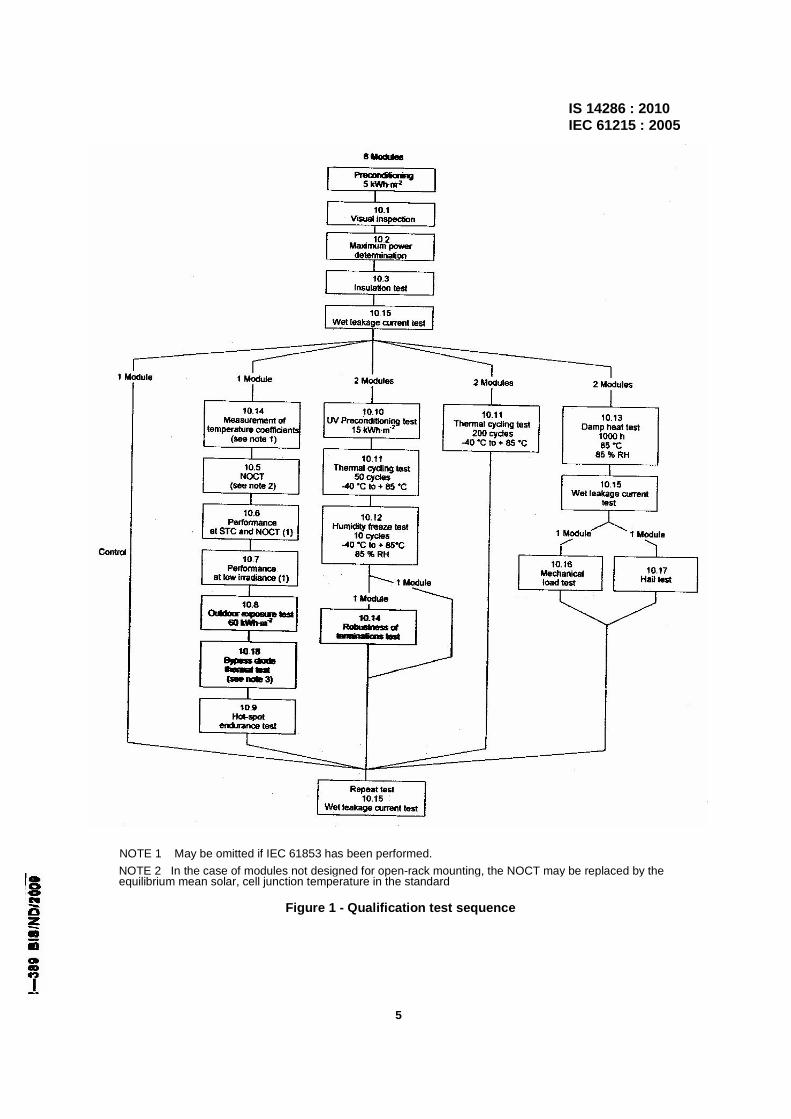
The modules shall be divided into groups and subjected to the qualification test sequences in Figure 1, carried out in the order laid down. Each box refers to the corresponding subclause in this standard. Test procedures and severities, including initial and final measurements where necessary, are detailed in Clause 10.
NOTE 1 Where the final measurements for one test serve as the initial measurements for the next test in the sequence, they need not be repeated. In these cases, the initial measurements are omitted from the test.
In carrying out the tests, the tester shall strictly observe the manufacturer's handling, mounting and connection instructions. Tests given in 10.4; 10.5, 10.6 and 10.7 may be omitted if future IEC 61853 has been or is scheduled to be run on this module type.
Test conditions are summarized in Table 1.
NOTE 2 The test levels in Table 1 are the minimum levels required for qualification. If the laboratory and the module manufacturer agree, the tests may be performed with increased severities.
6 Pass criteria
A module design shall be judged to have passed the qualification tests, and therefore to be IEC type approved, if each test sample meets all the following criteria:
a) the degradation of maximum output power does not exceed the prescribed limit after each test nor 8 % after each test sequence;
b) no sample has exhibited any open circuit during the tests;
c) there is no visual evidence of a major defect, as defined in Clause 7;
d) the insulation test requirements are met after the tests;
e) the wet leakage current test requirements are met at the beginning and the end of each sequence and after the damp heat test;
f) specific requirements of the individual tests are met.
If two or more modules do not meet these test criteria, the design shall be deemed not to have met the qualification requirements. Should one module fail any test, another two modules meeting the requirements of Clause 3 shall be subjected to the whole of the relevant test sequence from the beginning. If one or both of these modules also fail, the design shall be deemed not to have met the qualification requirements. If, however, both modules pass the test sequence, the design shall be judged to have met the qualification requirements.
7 Major visual defects
For the purposes of design qualification and type approval, the following are considered to be major visual defects:
a) broken, cracked, or torn external surfaces, including superstates, substrates, frames and junction boxes;
3

IS 14286 : 2010 IEC 61215 : 2005 b) bent or misaligned external surfaces, including superstates, substrates, frames and junction boxes to
the extent that the installation and/or operation of the module would be impaired.
c) a crack in a cell the propagation of which could remove more than 10 % of that cell's area from the electrical circuit of the module;
d) bubbles or delaminations forming a continuous path between any part of the electrical circuit and the edge of the module;
e) loss of mechanical integrity, to the extent that the installation and/or operation of the module would be impaired.
8 Report
Following type approval, a certified report of the qualification tests, with measured performance characteristics and details of any failures and re-tests, shall be prepared by the test agency in accordance with ISO/IEC 17025. The report shall contain the detail specification for the module. Each certificate or test report shall include at least the following information:
a) a title;
b) name and address of the test laboratory and location where the tests were carried out;
c) unique identification of the certification or report and of each page;
d) name and address of client, where appropriate;
e) description and identification of the item tested;
f) characterization and condition of the test item;
g) date of receipt of test item and date(s) of test, where appropriate;
h) identification of test method used;
i) reference to sampling procedure, where relevant;
j) any deviations from, additions to or exclusions from the test method, and any other information relevant to a specific tests, such as environmental conditions;
k) measurements, examinations and derived results supported by tables, graphs, sketches and photographs as appropriate including temperature coefficients of short-circuit current, open-circuit voltage and peak power, NOCT, power at NOCT, STC and low irradiance, spectrum of the lamp used for the UV pre-screening test, maximum power loss observed after all of the tests, and any failures observed;
I) a statement of the estimated uncertainty of the test results (where relevant);
m) a signature and title, or equivalent identification of the person(s) accepting responsibility for the content of the certificate or report, and the date of issue;
n) where relevant, a statement to the effect that the results relate only to the items tested;
o) a statement that the certificate or report shall not be reproduced except in full, without the written approval of the laboratory.
A copy of this report shall be kept by the manufacturer for reference purposes.
4
IS 14286 : 2010 IEC 61215 : 2005
NOTE 1 May be omitted if IEC 61853 has been performed. NOTE 2 In the case of modules not designed for open-rack mounting, the NOCT may be replaced by the equilibrium mean solar, cell junction temperature in the standard
Figure 1 - Qualification test sequence
5
IS 14286 : 2010 IEC 61215 : 2005
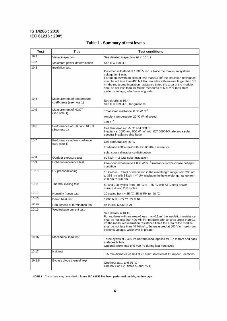
Table 1 - Summary of test levels
Test Title Test conditions 10.1 Visual inspection See detailed inspection list in 10.1.2 10.2 Maximum power determination See IEC 60904-1 10.3 Insulation test
Dielectric withstand at 1 000 V d.c. + twice the maximum systems voltage for 1 min. For modules with an area of less than 0.1 m2 the insulation resistance shaft be not less than 400 Mil. For modules with an area larger than 0.1 m2 the measured insulation resistance times the area of the module shall be not less than 40 Mil m2 measured at 500 V or maximum systems voltage, whichever is greater
10.4 Measurement of temperature coefficients (see note 1) See details in 10.4
See IEC 60904-10 for guidance.
10.5 Measurement of NOCT (see note 1 Total solar irradiance: 8.00 W m-2
Ambient temperature: 20 "C Wind speed:
1 m s~1 10.6 Performance at STC and NOCT
(See note 1) Cell temperature: 25 °C and NOCT Irradiance: 1000 and 800 W nrr2 with iEC 60904-3 reference solar spectral irradiance distribution
10.7 Performance at low irradiance (see note 1) Cell temperature: 25 "C
lrradiance:200 W-m-2 with IEC 60904-3 reference solar spectral irradiance distribution
10.8 Outdoor exposure test 60 kWh m-2 total solar irradiation 10.9 Hot-spot endurance test Five-hour exposure to 1 000 W m~2 irradiance in worst-case hot-spot
condition 10.10 UV preconditioning 15 kWh-m~ total UV irradiation in the wavelength range from 280 nm
to 385 nm with 5 kWh m~2 UV irradiation in the wavelength range from 280 nm to 320 rim
10.11 Thermal cycling test 50 and 200 cycles from -40 "C to + 85 "C with STC peak power current during 200 cycles
10.12 Humidity freeze test 10 cycles from + 85 "C, 85 % RH to -40 "C 10.13 Damp heat test 1 000 h at + 85 "C. 85 % RH 10.14 Robustness of termination test As in IEC 60068-2-21 10.15 Wet leakage current test
See details in 10.15 For modules with an area of less man 0.1 m2 the insulation resistance shall be not less than 400 Mil. For modules with an area larger than 0.1 m2 the measured insulation resistance times the area of the module shall be not less than 40 Mil m2 to be measured at 500 V or maximum systems voltage, whichever is greater
10.16 Mechanical load test Three cycles of 2 400 Pa unrform load, applied for 1 h to front and back surfaces hi him. Optional snow load of 5 400 Pa during last front cycle
10.17 Hail test 25 mm diameter ice ball at 23.0 mr', directed at 11 impact . locations
10.1.8 Bypass diode thermal' test One hour at /sc and 75 "C One hour at 1.25 times /sc and 75' C
NOTE 1 These tests may be omitted if future IEC 61853 has been performed on this, module type.
6
IS 14286 : 2010 IEC 61215 : 2005
9 Modifications
Any change in the design, materials, components or processing of the module may require a repetition of some or all of the qualification tests to maintain type approval.
10 Test procedures
10.1 Visual inspection
10.1.1 Purpose
To detect any visual defects in the module.
10.1.2 Procedure
Carefully inspect each module under an illumination of not less than 1 000 lux for the following conditions:
- cracked, bent, misaligned or torn external surfaces;
- broken cells;
- cracked cells;
- faulty interconnections or joints;
- cells touching one another or the frame;
- failure of adhesive bonds;
- bubbles or delaminations forming a continuous path between a cell and the edge of the
module;
- tacky surfaces of plastic materials;
- faulty terminations, exposed live electrical parts;
- any other conditions which may affect performance.
Make note of and/or photograph the nature and position of any cracks, bubbles or delaminations, etc. which may worsen and adversely affect the module performance in subsequent tests.
10.1.3 Requirements
Visual conditions other than the major visual defects listed in Clause 7 are acceptable for the purposes of type approval.
10.2 Maximum power determination
10.2.1 Purpose
To determine the maximum power of the module before and after the various environmental tests. Repeatability of the test is the most important factor.
10.2.2 Apparatus
a) A radiant source (natural sunlight or a solar simulator class B or better in accordance with IEC 60904-9).
7
IS 14286 : 2010 IEC 61215 : 2005 b) A PV reference device in accordance with IEC 60904-2 or I EC 60904-6. If a class B simulator is
used the reference device shall be a reference module of the same size with the same ceil technology (to match spectral response) as the test specimen.
c) A suitable mount for supporting the test specimen and the reference device in a plane normal to the radiant beam.
d) A means for monitoring the temperature of the test specimen and the reference device to an accuracy of ±1 °C and repeatability of ±0,5 °C.
e) Equipment for measuring the current of the test specimen and reference device to an accuracy of ±0,2 % of the reading;
f) Equipment for measuring the voltage of the test specimen and reference device to an accuracy of ±0,2 % of the reading.
10.2.3 Procedure
Determine the current-voltage characteristic of the module in accordance with IEC 60904-1 at a specific set of irradiance and temperature conditions (a recommended range is a ceil temperature between 25 °C and 50 °C and an irradiance between 700 W-m-2 and 1 100 W-m-2) using natural sunlight or a class B or better simulator conforming to the requirements of IEC 60904-9. In special circumstances when modules are designed for operation under a different range of conditions, the current-voltage characteristics can be measured using temperature and irradiance levels similar to the expected operating conditions. Temperature and irradiance corrections can be made in accordance with IEC 60891 in order to compare sets of measurements made on the same module before and after environmental tests. However, every effort should be made to assure that peak power measurements are made under similar operating conditions, that is minimize the magnitude of the correction by making all peak power measurements on a particular module at approximately the same temperature and irradiance. Repeatability of the maximum power measurement must be better than ±1 %.
NOTE Use the control module as a check every time the test modules are measured.
10.3 Insulation test
10.3.1 Purpose
The purpose is to determine whether or not the module is sufficiently well-insulated between current-carrying parts and the frame or the outside world.
10.3.2 Apparatus
a) DC voltage source, with current limitation, capable of applying 500 V or 1 000 V plus twice the maximum system voltage of the module according to 10.3.4 c).
b) An instrument to measure the insulation resistance.
10.3.3 Test conditions
The test shall be made on modules at ambient temperature of the surrounding atmosphere (see IEC 60068-1) and in a relative humidity not exceeding 75 %.
8
IS 14286:2010 IEC 61215 : 2005
10.3.4 Procedure
a) Connect the shorted output terminals of the module to the positive terminal of a d-C. insulation tester with a current limitation.
b) Connect the exposed metal parts of the module to the negative terminal of the tester. If the module has no frame or if the frame is a poor electrical conductor, wrap a conductive foil around the edges and over the back of the module. Connect the foil to the negative terminal of the tester.
c) Increase the voltage applied by the tester at a rate not exceeding 500 V s_1 to a maximum equal to 1 000 V plus twice the maximum system voltage (i.e. the maximum system voltage marked on the module by the manufacturer). If the maximum system voltage does not exceed 50 V, the applied voltage shall be 500 V. Maintain the voltage at this level for 1 min.
d) Reduce the applied voltage to zero and short-circuit the terminals of the test equipment to discharge the voltage build-up in the module.
e) Remove the short circuit.
f) Increase the voltage applied by the test equipment at a rate not to exceed 500 V-s~1 to 500 V or the maximum system voltage for the module, whichever is greater. Maintain the voltage at this level for 2 min. Then determine the insulation resistance.
g) Reduce the applied voltage to zero and short-circuit the terminals of the test equipment to discharge the voltage build-up in the module.
h) Remove the short circuit and disconnect the test equipment from the module.
NOTE If the module does not have a metal frame nor a glass superstate, the insulation test should be repeated with the metallic plate placed on the front of the module as in 10.3.4b).
10.3.5 Test requirements
The following requirements are necessary:
- no dielectric breakdown or surface tracking during step c);
- for modules with an area of less than 0.1 m2 the insulation resistance shall be not less than 400 MQ;
- for modules with an area larger than 0,1 m2 the measured insulation resistance times the area of the module shall be not less than 40 MQ-m2.
10.4 Measurement of temperature coefficients
10.4.1 Purpose
The purpose is to determine the temperature coefficients of current (α), voltage (β) and peak power (δ) from module measurements. The coefficients so determined are valid at the irradiance at which the measurements were made. See IEC 60904-10 for evaluation of module temperature coefficients at different irradiance levels.
10.4.2 Apparatus
The following apparatus is required to control and measure the test conditions:
a) a radiant source (natural sunlight or solar simulator, class B or better in accordance with IEC 60904-9) of the type to be used in subsequent tests;
9

IS 14286 : 2010 IEC 61215 : 2005 b) a PV reference device having a known short-circuit current versus irradiance characteristic
determined by calibrating against an absolute radiometer in accordance with IEC 60904-2 or IEC 60904-6;
c) any equipment necessary to change the temperature of the test specimen over the range of interest;
d) a suitable mount for supporting the test specimen and the reference device in the same plane normal to the radiant beam;
e) a means for monitoring the temperature of the test specimen and reference device to an accuracy of ±1 °C, and repeatability of ±0,5 °C;
f) equipment for measuring the current of the test specimen and reference device to an accuracy of ±0,2 % of the reading;
g) equipment for measuring the voltage of the test specimen and reference device to an accuracy of ±0,2 % of the reading;
10.4.3 Procedure
There are two acceptable procedures for measuring the temperature coefficients.
10.4.3.1 Procedure in natural sunlight
a) Measurement in natural sunlight shall only be made when:
- the total irradiance is at least as high as the upper limit of the range of interest;
- the irradrance variation caused by short-term oscillations (clouds, haze, or smoke) is iess than ±2 % of the total irradiance as measured by the reference device;
- the wind speed is iess than 2 m-s~1.
b) Mount the reference device co-planar with the test module so that both are normal to the direct solar beam within ±5°. Connect to the necessary instrumentation. NOTE The measurements described in the following subclauses should be made as expeditiously as possible within a few hours on the same day to minimize the effect of changes in the spectral conditions. If not, spectral corrections may be required.
c) If the test module and reference device are equipped with temperature controls, set the controls at the desired level.
d) If temperature controls are not used, shade the specimen and the reference device from the sun and wind until its temperature is uniform within ±1 °C of the ambient air temperature, or allow the test specimen to equilibrate to its stabilized temperature, or cool the test specimen to a point below the required test temperature and then let the module warm up naturally. The reference device should also stabilize within ±1 °C of its equilibrium temperature before proceeding.
e) Record the current-voltage characteristic and temperature of the specimen concurrently with recording the short-circuit current and temperature of the reference device at the desired temperatures. If necessary, make the measurements immediately after removing the shade.
f) The irradiance (I 0 shall be calculated in accordance with IEC 60891 from the measured current (/sc) of the PV reference device, and its calibration value at STC (/rc). A correction should be applied to account for the temperature of the reference device Tm using the specified temperature coefficient of the reference device αTC
10
IS 14286 : 2010 IEC 61215 : 2005
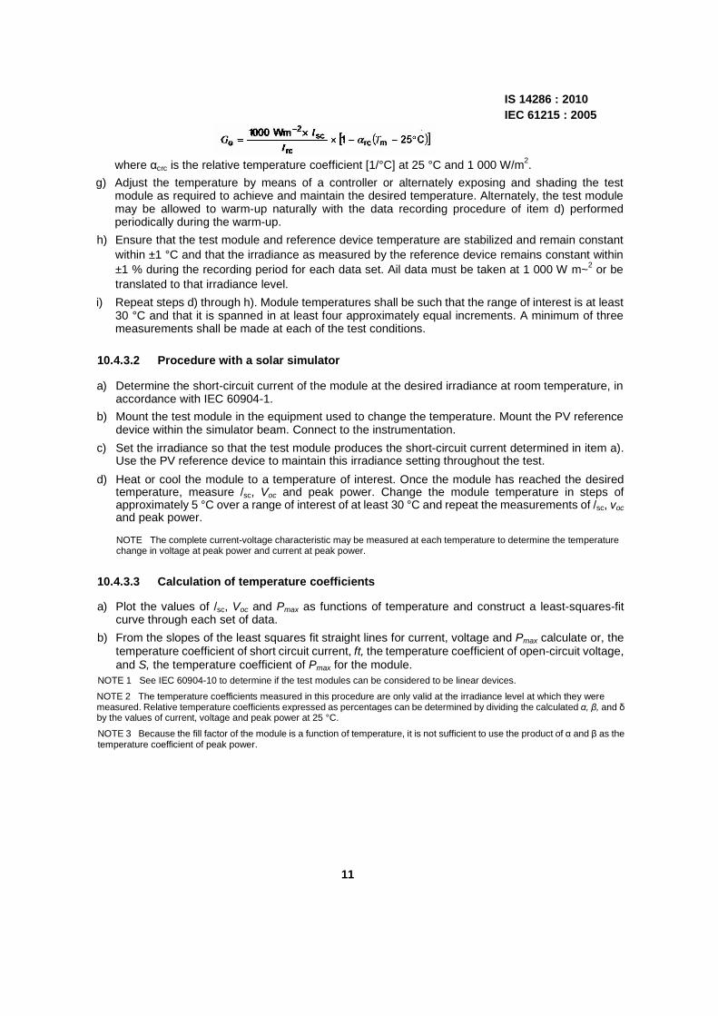
where αcrc is the relative temperature coefficient [1/°C] at 25 °C and 1 000 W/m2.
g) Adjust the temperature by means of a controller or alternately exposing and shading the test module as required to achieve and maintain the desired temperature. Alternately, the test module may be allowed to warm-up naturally with the data recording procedure of item d) performed periodically during the warm-up.
h) Ensure that the test module and reference device temperature are stabilized and remain constant within ±1 °C and that the irradiance as measured by the reference device remains constant within ±1 % during the recording period for each data set. Ail data must be taken at 1 000 W m~2 or be translated to that irradiance level.
i) Repeat steps d) through h). Module temperatures shall be such that the range of interest is at least 30 °C and that it is spanned in at least four approximately equal increments. A minimum of three measurements shall be made at each of the test conditions.
10.4.3.2 Procedure with a solar simulator
a) Determine the short-circuit current of the module at the desired irradiance at room temperature, in accordance with IEC 60904-1.
b) Mount the test module in the equipment used to change the temperature. Mount the PV reference device within the simulator beam. Connect to the instrumentation.
c) Set the irradiance so that the test module produces the short-circuit current determined in item a). Use the PV reference device to maintain this irradiance setting throughout the test.
d) Heat or cool the module to a temperature of interest. Once the module has reached the desired temperature, measure /sc, Voc and peak power. Change the module temperature in steps of approximately 5 °C over a range of interest of at least 30 °C and repeat the measurements of /sc, voc and peak power.
NOTE The complete current-voltage characteristic may be measured at each temperature to determine the temperature change in voltage at peak power and current at peak power.
10.4.3.3 Calculation of temperature coefficients
a) Plot the values of /sc, Voc and Pmax as functions of temperature and construct a least-squares-fit curve through each set of data.
b) From the slopes of the least squares fit straight lines for current, voltage and Pmax calculate or, the temperature coefficient of short circuit current, ft, the temperature coefficient of open-circuit voltage, and S, the temperature coefficient of Pmax for the module.
NOTE 1 See IEC 60904-10 to determine if the test modules can be considered to be linear devices.
NOTE 2 The temperature coefficients measured in this procedure are only valid at the irradiance level at which they were measured. Relative temperature coefficients expressed as percentages can be determined by dividing the calculated α, β, and δ by the values of current, voltage and peak power at 25 °C.
NOTE 3 Because the fill factor of the module is a function of temperature, it is not sufficient to use the product of α and β as the temperature coefficient of peak power.
11
IS 14286 : 2010 IEC 61215 : 2005
10.5 Measurement of nominal operating ceil temperature (NOCT)
10.5.1 Purpose
To determine the NOCT of the module.
10.5.2 Introduction
NOCT is defined as the equilibrium mean solar cell junction temperature within an open- rack mounted module in the following standard reference environment (SRE):
- tilt angle: 45° from the horizontal
- total irradiance: 800 W.m-2
- ambient temperature: 20 °C
- wind speed: 1 m-s-1
- electrical load: nil (open circuit).
NOCT can be used by the system designer as a guide to the temperature at which a module will operate in the field and it is therefore a useful parameter when comparing the performance of different module designs. However, the actual operating temperature at any particular time is affected by the mounting structure, irradiance, wind speed, ambient temperature, sky temperature and reflections and emissions from the ground and nearby objects. For accurate performance predictions, these factors shall be taken into account.
Two methods for determining NOCT are described.
The first, called "the primary method", is universally applicable to all PV modules. In the case of modules not designed for open-rack mounting, the primary method may be used to determine the equilibrium mean solar cell junction temperature in the SRE, with the module mounted as recommended by the manufacturer.
The second, called "the reference-plate method", is faster but is applicable only to PV modules of the type which respond to changes of ambient temperature (within restricted ranges of wind speed and irradiance) in the same way as the reference plates used in the measurement. Crystalline silicon modules with a glass front and plastic back are in this category. The reference plates are calibrated using the same procedure as in the primary method.
10.5.3 Primary method
10.5.3.1 Principle
This method is based on gathering actual measured cell temperature data under a range of environmental conditions including the SRE. The data are presented in a way that allows accurate and repeatabte interpolation of the NOCT.
The temperature of the solar cell junction (T j) is primarily a function of the ambient temperature (Tamb). the average wind speed (i) and the total solar irradiance (G) incident on the active surface of the module. The temperature difference (T j – Tamb)
is largely independent of the ambient temperature and is essentially linearly proportional to the irradiance at levels above 400 W m-2. The procedure calls for plotting (T j – Tamb) against G
12
IS 14286 : 2010 IEC 61215 : 2005
for a period when wind conditions are favorable. A preliminary NOCT value is then determined by adding 20 °C to the value of (T j – Tamb) interpolated at the SRE irradiance of 800 WM
2. Finally, a correction factor, dependent on the average temperature and wind speed during the test period, is added to the preliminary NOCT to correct it to 20 °C and 1 m-s'1.
10.5.3.2 Apparatus
The following apparatus is required:
a) an open rack to support the test module(s) and pyranometer in the specified manner (see 10.5.3.3). The rack shall be designed to minimize heat conduction from the modules and to interfere as little as possible with the free radiation of heat from their front and back surfaces; NOTE In the case of modules not designed for open-rack mounting, the test module(s) should be mounted as recommended by the manufacturer.
b) a pyranometer, mounted in the plane of the module(s) and within 0,3 m of the test array;
c) instruments to measure wind speed down to 0,25 m s-1 and wind direction, installed approximately 0,7 m above the top of the module(s) and 1,2 m to the east or west;
d) an ambient temperature sensor, with a time constant equal to or less than that of the module(s), installed in a shaded enclosure with good ventilation near the wind sensors;
e) cell temperature sensors, attached by solder or thermally conductive adhesive to the backs of two solar cells near the middle of each test module, or other equipment necessary for lEC-approved measurement of cell temperature;
f) a data acquisition system with temperature measurement accuracy of ±1 °C to record the following parameters within an interval of no more than 5 s:
- irradiance,
- ambient temperature,
- cell temperature,
- wind speed, - wind direction.
10.5.3.3 Test module mounting
Tilt angle: the test module(s) shall be positioned so that it (they) is (are) tilted at 45° ± 5° to the horizontal with the front side pointed toward the equator.
Height: the bottom edge of the test module(s) shall be 0,6 m or more above the local horizontal plane or ground level.
Configuration: to simulate the thermal boundary conditions of modules installed in an array, the test module(s) shall be mounted within a planar surface that extends at least 0,6 m beyond the module(s) in all directions. For modules designed for free-standing, open-back installations, black aluminum plates or other modules of the same design shall be used to fill out the remaining open area of the planar surface.
13

14286 : 2010 IEC 61215 : 2005 Surrounding area: there shall be no obstructions to prevent full irradiance of the test module(s) during the period from 4 h before local solar noon to 4 h after local solar noon. The ground surrounding the module(s) shall not have an abnormally high solar reflectance and shall be flat and level or sloping away from the test fixture in all directions. Grass, other types of vegetation, black asphalt or dirt are acceptable for the local surrounding area.
10.5.3.4 Procedure
a) Set up the apparatus with the test modules), as described in 10.5.3.3. Ensure that the test module(s) are open-circuited.
b) On a suitable, clear, sunny day with little wind, record, as a function of time, the cell temperature, the ambient temperature, the irradiance, wind speed and wind direction.
c) Reject all data taken during the following conditions:
- irradiance below 400 W m-2;
- in a 10-min interval after the irradiance varies by more than 10 % from the maximum value to the minimum value recorded during that 10 min period;
- wind speeds outside the range 1 m s-1 ± 0,75 m.s-1;
- ambient temperatures outside the range 20 °C ± 15 °C or varying by more than 5 °C from the maximum to the minimum value recorded during one data collection run;
- in a 10-min interval after a wind gust of more than 4 ms~1;
- wind direction within ±20° of east or west.
d) From a minimum of 10 acceptable data points covering an irradiance range of at least 300 W m~2, making sure that data points are from both before and after solar noon, plot (T j – Tamb) as a function of irradiance. Use regression analysis to fit the data points.
e) Determine the value of (T j – Tamb) at 800 W-m-2 and add 20 °C to give the preliminary value of NOCT.
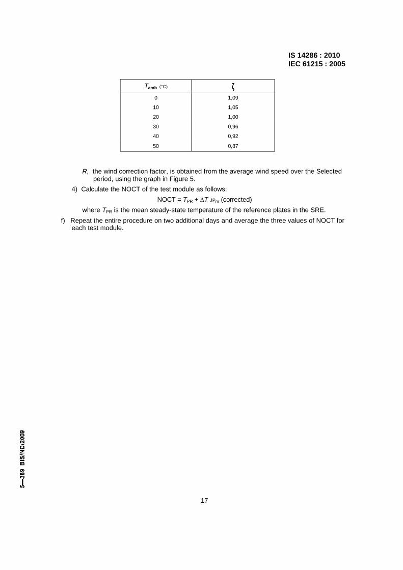
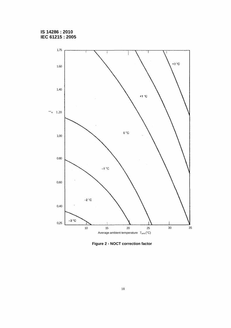
f) Calculate the average ambient temperature, Tamb, and the average wind speed, T, associated with the acceptable data points and determine the appropriate correction factor from Figure 2.
g) Add the correction factor to the preliminary NOCT to correct it to 20 °C and 1 m s~1. This sum is the NOCT of the module.
h) Repeat the entire procedure on two additional days and average the three values of NOCT for each test module.
10.5.4 Reference-plate method
10.5.4.1 Principle
This method is based on the principle of comparing the temperature of/the test module(s) with that of standard reference plates under the same conditions of irradiance, ambient temperature and wind speed. The steady-state temperature of the reference plate in the SRE is determined using the primary method described in 10.5.3.
14
IS 14286 : 2010 IEC 61215 : 2005
The NOCT of the test module is obtained by correcting the temperature difference between the test module and the reference plates to the SRE and adding this value to the mean steady-state temperature of the reference plates in the SRE. It has been established that the measured temperature difference is insensitive to fluctuations in irradiance and to small changes in ambient temperature and wind speed.
10.5.4.2 Reference plate
The reference plates shall be made of hard aluminum alloy to the dimensions shown in Figure 3. The front surface shall be painted matte black and the back surface gloss white. Means shall be provided for measuring the temperature of the reference plates to the required accuracy. One method employing two thermocouples is shown in Figure 3. One thermocouple is cemented into each branch of the milled groove with thermally conductive and electrically insulating adhesive, after removing any insulation for a distance of 25 mm from the junction. The remainder of the thermocouple wires are finally cemented into the groove with conductive putty.
At least three reference plates shall be made and calibrated, using the primary method described in 10.5.3. The steady-state temperatures so determined shall be within the range 46 °C to 50 °C and shall differ by no more than 1 °C. One of the reference plates shall be kept unused as a control. Before making a NOCT measurement, the steady-state temperatures of the reference plates shall be checked against that of the control plate under the acceptable conditions indicated in item c) of 10.5.3.4 to detect any change in their thermal properties. If the measured temperatures of the reference plates differ by more than 1 °C, the reason for this shall be investigated and necessary corrective action taken before proceeding with the test.
10.5.4.3 Test site
Select a fiat test site with negligible wind disturbance from buildings, trees and topographical features. Non-uniform reflections from the ground and objects behind the test plane shall be avoided.
10.5.4.4 Apparatus
The following apparatus is required (see Figure 4).
a) A number of reference plates, as described in 10.5.4.2 (one more than the number of modules to be tested simultaneously).
b) A pyranometer or a PV reference device.
c An open rack to support the test module(s), reference plates and pyranometer tilted at 45° ± 5° to the horizontal with the front side toward the equator. Each module shall be closely flanked by two reference plates with the lower edge of the module(s) approximately 1 m above the ground. The rack shall be designed to minimize heat conduction from the module(s) and plates and to interfere as little as possible with the free radiation of heat from their front and back surfaces.
d) Instruments to measure wind speed down to 0,25 m s~1 and wind direction, installed approximately 0,7 m above the top of the module(s) and 1,2 m to the east or west, as shown in Figure 4.
e) An ambient temperature sensor with a time constant equal to or less than that of the modules, installed in a shaded enclosure with good ventilation near the wind sensors.
15

IS 14286 : 2010 IEC 61215 : 2005
f) Cell temperature sensors, attached by solder or thermally conductive adhesive to the backs of two solar cells near the middle of each module, or other equipment necessary for lEC-approved measurement of cell temperature.
g) A data acquisition system with temperature measurement accuracy of ±1 °C to record the following parameters within an interval of no more than 5 s:
- irradiance;
- ambient temperature;
- cell temperature;
- wind speed;
- wind direction;
- reference-plate temperatures.
10.5.4.5 Procedure
a) Set up the apparatus with the test module(s) and reference plates as shown in Figure 4. Ensure that the test module(s) are open-circuited.
b) On a suitable, clear, sunny day with little wind, record, as a function of time, the cell temperature(s) of the test module(s). the reference-plate temperature, irradiance, ambient temperature, wind speed and wind direction.
c) Reject all data taken during, or for 15 min after, the following conditions:
- irradiance below 750 W m-2 or above 850 W m-2;
- irradiance varying by more than ± 40 W m-2 during one data collection run;
- wind speeds above 2 m-s-1 that continue for more than 30 s;
- wind speeds below 0,5 m-s-1;
- wind direction within ±20° of east or west;
- differences between temperatures of the reference plates greater than 1 °C.
d) For each data point in the selected period, take the mean temperature Tp of all the reference plates.
e) For each data point in the selected period and for each test module:
1) take the mean cell temperature T j and calculate:
∆T JP = T J – T P If ∆T JP varies by more than 4 X, the reference plate method is not applicable and the primary method described in 10.5.3 shall be used.
2) Average all values of ∆T JP to give ∆T JPm.
3) Correct ∆T JPm to the SRE as follows:
∆T JPm (corrected) = (ƒlζR) ∆T JPm (uncorrected)
where
ƒ, the irradiance correction factor, is 800 divided by the average irradiance over the selected period;
ζ, the ambient temperature correction factor, is obtained from the average ambient temperature Tamb over the selected period using the following table (linear interpolation for C, values is acceptable).
16
IS 14286 : 2010 IEC 61215 : 2005
Tamb (°C) ζ 0 1,09
10 1,05
20 1,00
30 0,96
40 0,92
50 0,87
R, the wind correction factor, is obtained from the average wind speed over the Selected period, using the graph in Figure 5.
4) Calculate the NOCT of the test module as follows:
NOCT = TPR + ∆T JPm (corrected)
where TPR is the mean steady-state temperature of the reference plates in the SRE.
f) Repeat the entire procedure on two additional days and average the three values of NOCT for each test module.
17
IS 14286 : 2010 IEC 61215 : 2005
1,75
1.60
1,40
""« 1.20
1,00
0.80
0,60
0,40
0,25 10 15 20 25
Average ambient temperature 7amb ("C) 30 35
Figure 2 - NOCT correction factor
18

IS 14286 : 2010 IEC 61215 : 2005
Figure 3 - Reference plate
Figure 4 - NOCT measurement by reference plate method
19

IS 14286 : 2010 lEC 61215 : 2005
Figure 5 - Wind correction factor
10.6 Performance at STC and NOCT
10.6.1 Purpose
To determine how the electrical performance of the module varies with load at STC (1 000Wm-2, 25 °C cell temperature, with the lEC 60904-3 reference solar spectra! irradiance distribution) and at NOCT and an irradiance of 800 W.m-2, with the lEC 60904-3 reference solar spectral irradiance distribution.
10.6.2 Apparatus
a) A radiant source (natural sunlight or a solar simulator class B or better) in accordance with lEC 60904-9.
b) A PV reference device in accordance with lEC 60904-2 or lEC 60904-6. If a class B simulator is used, the reference device shall be a reference module of the same size with the same cell technology to match spectral response.
20
IS 14286 : 2010 IEC 61215 : 2005
c) A suitable mount for supporting the test specimen and the reference device in a plane normal to the radiant beam.
d) A means for monitoring the temperature of the test specimen and the reference device to an accuracy of +1 "C and repeatability of ±0,5 °C.
e) Equipment for measuring the current of the test specimen and reference device to an accuracy of ±0,2 % of the reading.
f) Equipment for measuring the voltage of the test specimen and reference device to an accuracy of ±0,2 % of the reading.
g) Equipment necessary to change the temperature of the test specimen to the NOCT temperature measured in 10.5.
10.6.3 Procedure
10.6.3.1 STC
Maintain the module at 25 °C and trace its current-voltage characteristic at an irradiance of 1 000 Wrrv~2 (as measured by a suitable reference device), in accordance with IEC 60904-1, using natural sunlight or a class B or better simulator conforming to the requirements of IEC 60904-9.
10.6.3.2 NOCT
Heat the module uniformly to NOCT and trace its current-voltage characteristic at an irradiance of 800 Wrrr"2 (as measured by a suitable reference device), in accordance with IEC 60904-1, using natural sunlight or a class B or better simulator conforming to the requirements of the IEC 60904-9.
If the reference device is not spectrally matched to the test module, use IEC 60904-7 to calculate the spectral mismatch correction.
10.7 Performance at low irradiance
10.7.1 Purpose
To determine how the electrical performance of the module varies with load at 25 °C and an irradiance of 200 Wm-2 (as measured by a suitable reference device), in accordance with IEC 60904-1 using natural sunlight or a simulator class B or better conforming to the requirements of IEC 60904-9.
10.7.2 Apparatus
a) A radiant source (natural sunlight or a solar simulator class B or better) in accordance with IEC 60904-9.
b) Equipment necessary to change the irradiance to 200 Wm-2 without affecting the relative spectral irradiance distribution and the spatial uniformity in accordance with IEC 60904-10.
c) A PV reference device in accordance with IEC 60904-2 or IEC 60904-6.
d) A suitable mount for supporting the test specimen and the reference device in a plane normal to the radiant beam.
e) A means for monitoring the temperature of the test specimen and the reference device to an accuracy of ±1 °C and repeatability of ±0,5 °C.
f) Equipment for measuring the current of the test specimen and reference device to an accuracy of ±0,2 % of the reading.
g) Equipment for measuring the voltage of the test specimen and reference device to an accuracy of ±0,2 % of the reading.
21

IS 14286 : 2010 IEC 61215 : 2005
10.7.3 Procedure
Determine the current-voltage characteristic of the module at 25 °C ± 2 °C and an irradiance of 200 W.m-2 (as measured by a suitable reference device), in accordance with IEC 60904-1 using natural sunlight or a class B or better simulator conforming to the requirements of IEC 60904-9. The irradiance shall be reduced to the specified level by using neutral filters or some other technique, which does not affect the spectral irradiance distribution. (See IEC 60904-10 for guidance on reducing the irradiance without changing the spectral irradiance distribution.)
10.8 Outdoor exposure test
10.8.1 Purpose
To make a preliminary assessment of the ability of the module to withstand exposure to outdoor conditions and to reveal any synergistic degradation effects which may not be detected by laboratory tests.
NOTE Caution should be taken in making absolute judgements about module life on the basis of passing this test because of the shortness of the test and the environmental variability of the test conditions. This test should only be used as a guide or indicator of possible problems.
10.8.2 Apparatus
a) A device capable of measuring solar irradiation, with an uncertainty of less than ±5 %.
b) Means to mount the module, as recommended by the manufacturer, co-planar with the irradiation measuring device.
c) A load sized such that at STC the module will operate near the maximum power point.
10.8.3 Procedure
a) Attach the resistive load to the module and mount it outdoors, as recommended by the manufacturer, co-planar with the irradiation monitor. Any hot-spot protective devices recommended by the manufacturer shall be installed before the module is tested.
b) Subject the module to an irradiation totalling 60 kWh.m-2, as measured by the monitor, under conditions conforming to general open-air climates, as defined in IEC 60721-2-1.
10.8.4 Final measurements
Repeat the tests of 10.1, 10.2 and 10.3.
10.8.5 Requirements
The requirements are as follows:
- no evidence of major visual defects, as defined in Clause 7;
- the degradation of maximum output power shall not exceed 5 % of the value measured before the test;
- insulation resistance shall meet the same requirements as for the initial measurements.
22
IS 14286 : 2010 IEC 61215 : 2005
10.9 Hot-spot endurance test
10.9.1 Purpose
The purpose of this test is to determine the ability of the module to withstand hot-spot heating effects, for example solder melting or deterioration of the encapsulation. This defect could be provoked by cracked or mismatched cells, interconnect failures, partial shadowing or soiling.
10.9.2 Hot-spot effect
Hot-spot heating occurs in a module when its operating current exceeds the reduced short-circuit current of a shadowed or faulty cell or group of ceils within it. When such a condition occurs, the affected cell or group of cells is forced into reverse bias and must dissipate power, which can cause overheating.
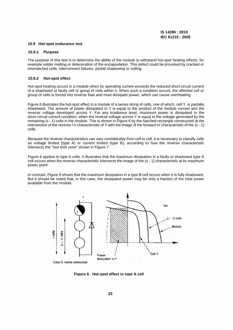
Figure 6 illustrates the hot-spot effect in a module of a series string of cells, one of which, cell Y, is partially shadowed. The amount of power dissipated in Y is equal to the product of the module current and the reverse voltage developed across Y. For any irradiance level, maximum power is dissipated in the short-circuit current condition, when the reverse voltage across Y is equal to the voltage generated by the remaining (s - 1) cells in the module. This is shown in Figure 6 by the hatched-rectangle constructed at the intersection of the reverse l-V characteristic of Y with the image of the forward IV characteristic of the (s - 1) cells.
Because the reverse characteristics can vary considerably from cell to cell, it is necessary to classify cells as voltage limited type A) or current limited (type B), according to how the reverse characteristic intersects the "test limit zone" shown in Figure 7
Figure 6 applies to type A cells. It illustrates that the maximum dissipation in a faulty or shadowed type A cell occurs when the reverse characteristic intersects the image of the (s - 1) characteristic at its maximum power point.
In contrast, Figure 8 shows that the maximum dissipation in a type B cell occurs when it is fully shadowed. But it should be noted that, in this case, the dissipated power may be only a fraction of the total power available from the module.
Figure 6 - Hot-spot effect in type A cell
23

IS 14286 : 2010 IEC 61215 : 2005
Figure 7 - Reverse characteristics
Figure 8 - Hot-spot effect in type B cell
10.9.3 Classification of cell interconnection
Solar cells in a PV module are connected in one of the following ways:
Case S: series connection of s cells in a single string;
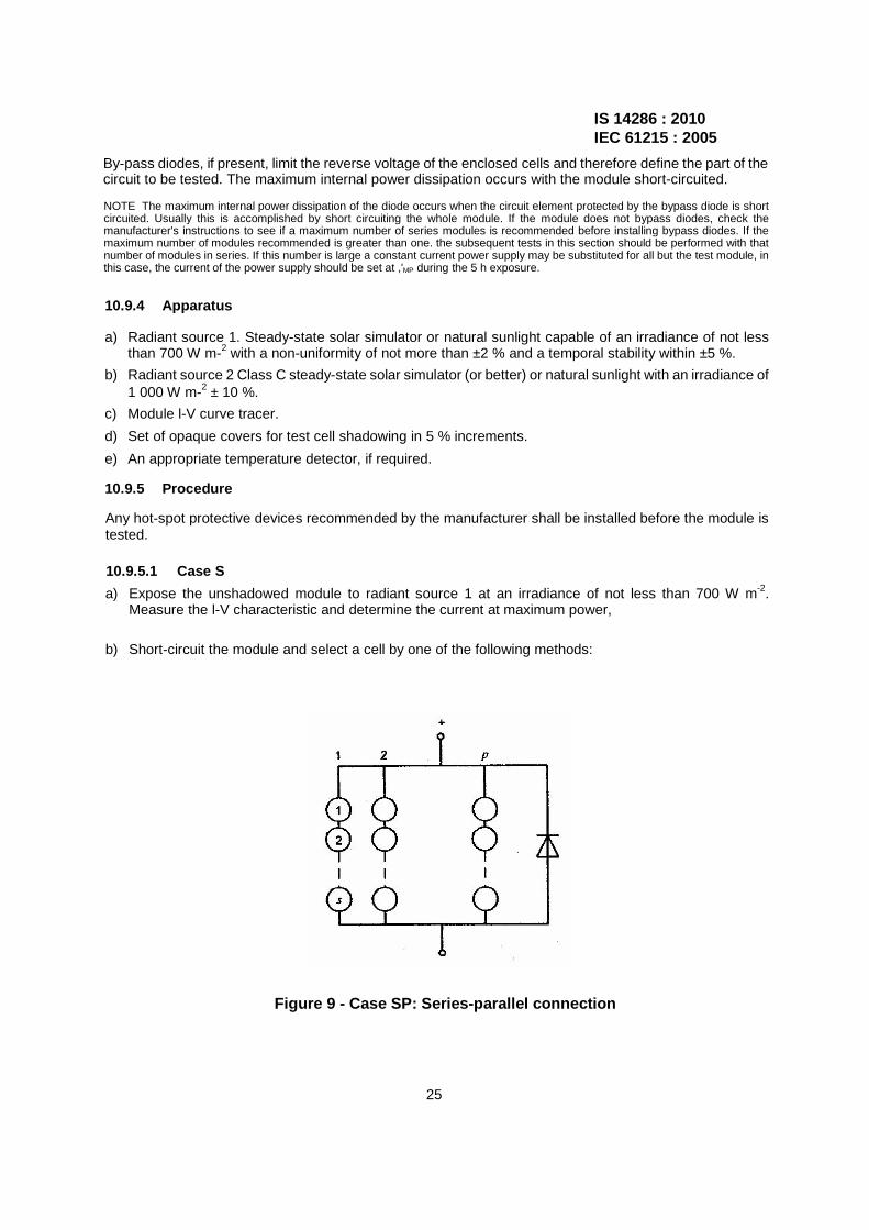
Case SP: series-parallel connection, i.e. a parallel connection of p strings, each with s cells in series; see Figure 9;
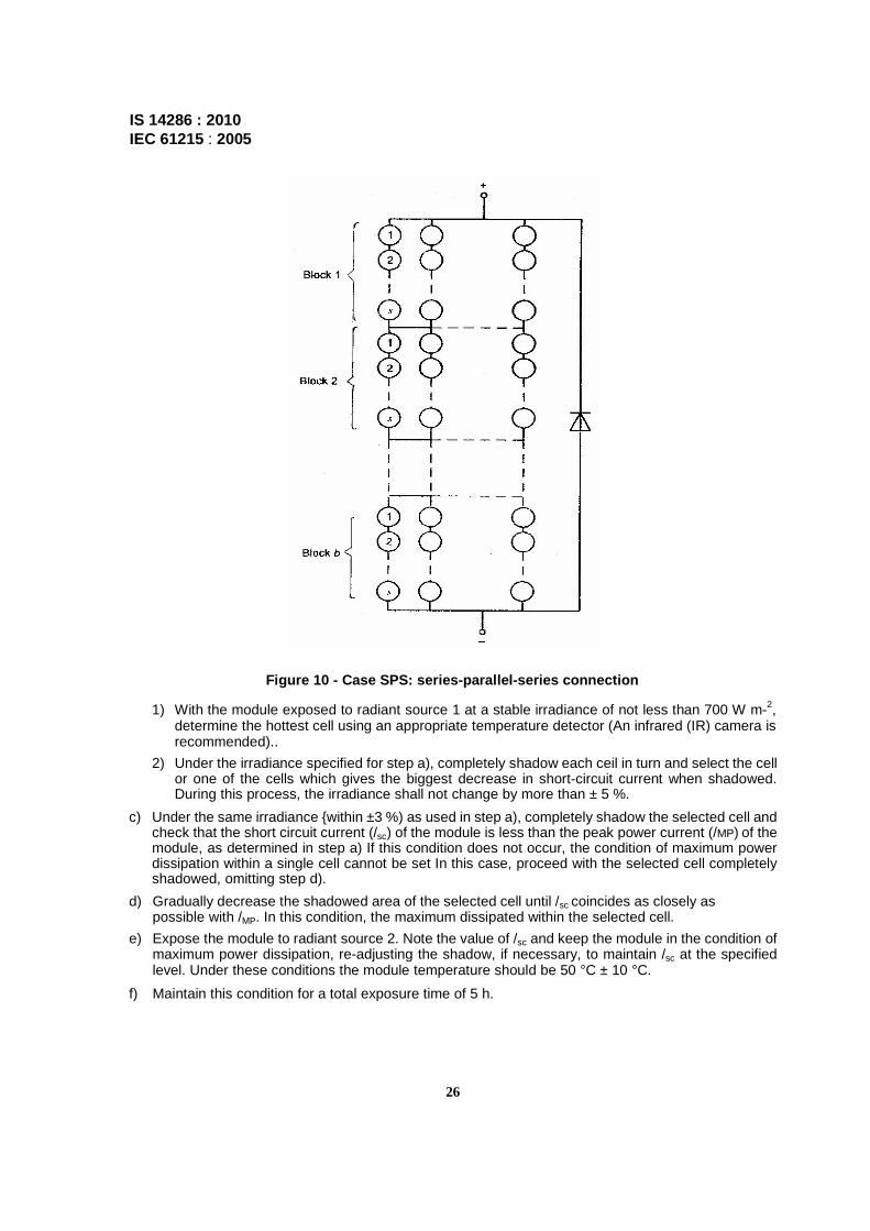
Case SPS: Series-parallel-series connection, i.e. a series connection of b blocks, where each block consists of a parallel connection of p strings, each with s cells in series. See Figure 10.
24
Power dissipation
Y (fully shadowed)
IS 14286 : 2010 IEC 61215 : 2005
By-pass diodes, if present, limit the reverse voltage of the enclosed cells and therefore define the part of the circuit to be tested. The maximum internal power dissipation occurs with the module short-circuited.
NOTE The maximum internal power dissipation of the diode occurs when the circuit element protected by the bypass diode is short circuited. Usually this is accomplished by short circuiting the whole module. If the module does not bypass diodes, check the manufacturer's instructions to see if a maximum number of series modules is recommended before installing bypass diodes. If the maximum number of modules recommended is greater than one. the subsequent tests in this section should be performed with that number of modules in series. If this number is large a constant current power supply may be substituted for all but the test module, in this case, the current of the power supply should be set at ,'MP during the 5 h exposure.
10.9.4 Apparatus
a) Radiant source 1. Steady-state solar simulator or natural sunlight capable of an irradiance of not less than 700 W m-2 with a non-uniformity of not more than ±2 % and a temporal stability within ±5 %.
b) Radiant source 2 Class C steady-state solar simulator (or better) or natural sunlight with an irradiance of 1 000 W m-2 ± 10 %.
c) Module l-V curve tracer.
d) Set of opaque covers for test cell shadowing in 5 % increments.
e) An appropriate temperature detector, if required.
10.9.5 Procedure
Any hot-spot protective devices recommended by the manufacturer shall be installed before the module is tested.
10.9.5.1 Case S
a) Expose the unshadowed module to radiant source 1 at an irradiance of not less than 700 W m-2. Measure the l-V characteristic and determine the current at maximum power,
b) Short-circuit the module and select a cell by one of the following methods:
Figure 9 - Case SP: Series-parallel connection
25
IS 14286 : 2010 IEC 61215 : 2005
Figure 10 - Case SPS: series-parallel-series connection
1) With the module exposed to radiant source 1 at a stable irradiance of not less than 700 W m-2, determine the hottest cell using an appropriate temperature detector (An infrared (IR) camera is recommended)..
2) Under the irradiance specified for step a), completely shadow each ceil in turn and select the cell or one of the cells which gives the biggest decrease in short-circuit current when shadowed. During this process, the irradiance shall not change by more than ± 5 %.
c) Under the same irradiance within ±3 %) as used in step a), completely shadow the selected cell and check that the short circuit current (/sc) of the module is less than the peak power current (/MP) of the module, as determined in step a) If this condition does not occur, the condition of maximum power dissipation within a single cell cannot be set In this case, proceed with the selected cell completely shadowed, omitting step d).
d) Gradually decrease the shadowed area of the selected cell until /sc coincides as closely as possible with /MP. In this condition, the maximum dissipated within the selected cell.
e) Expose the module to radiant source 2. Note the value of /sc and keep the module in the condition of maximum power dissipation, re-adjusting the shadow, if necessary, to maintain /sc at the specified level. Under these conditions the module temperature should be 50 °C ± 10 °C.
f) Maintain this condition for a total exposure time of 5 h.
26
IS 14286 : 2010 lEC 61215 : 2005
10.9.5.2 Case SP
a) Expose the unshadowed module to radiant source 1 at an irradiance of not less than 700 W-m-2. Measure the t-V characteristic and determine /sc (*), the short-circuit current corresponding to the condition of maximum hot spot power dissipation, from the following equation, assuming that all strings generate the same current:
ISC (*) = ISC . (p – 1) I p + (IPM I p)
where
/sc is the short-circuit current of the unshadowed module;
/MP is the current at maximum power of the unshadowed module;
p is the number of parallel strings in the module.
b) Short-circuit the module and select a cell by one of the following methods:
1) with the module exposed to radiant source 1 at a stable irradiance of not less than 700 W-m-z, determine the hottest cell using an appropriate temperature detector;
2) under the irradiance specified in step a), completely shadow each cell in turn and find the cell which gives the biggest decrease in short-circuit current when shadowed. During this process, the irradiance shall not change by more than ±5 %.
c) Under the same irradiance as in step a) (within ±3 %), check that, with the selected cell fully shadowed, /sc of the module is less than /sc (*), as determined in step a), if this condition does not occur, the condition of maximum power dissipation within a single cell cannot be set. In this case, proceed with the selected cell fully shadowed, omitting step d).
d) Gradually decrease the shadowed area of the selected cell until /SC °f the module coincides as closely as possible with /sc (*). In this condition, the maximum power is dissipated within the selected cell.
e) Expose the module to radiant source 2. Note the value of /SC and keep the module in the condition of maximum power dissipation, re-adjusting the shadow, if necessary, to maintain /sc at the specified level- Under these conditions the module temperature should be 50 °C±10 °C.
f) Maintain this condition for a total exposure time of 5 h.
10.9.5.3 Case SPS
a) Short-circuit the unshadowed module and expose it to radiant source 1 at a stable irradiance of not less than 700 W m-2. Take at random at least 30 % of the cells in the module, fully shadow each ceil in turn and measure the temperature at which it stabilizes, using thermal imaging equipment or other appropriate means.
b) Fully shadow the hottest cell found in step a).
c) While continuing to monitor its temperature, gradually decrease the shadowed area and determine the condition in which maximum temperature is achieved.
d) Expose the module to radiant source 2 and keep it in the shadowed condition established in step c). Under these conditions the module temperature should be 50 °C ± 10 °C.
e) Maintain this condition for a total exposure time of 5 h.
27
IS 14286 : 2010 IEC 61215 : 2005
10.9.6 Final measurements
Repeat the tests of 10.1, 10.2 and 10.3.
10.9.7 Requirements
The requirements are as follows:
- no evidence of major visual defects, as defined in Clause 7. If there is evidence of serious damage that does not qualify as a major visual defect, repeat the test on 2 additional cells. If there is no visual damage around either of these two cells the module type passes the hot spot test;
- the degradation of maximum output power shall not exceed 5 % of the value measured before the test;
- insulation resistance shall meet the same requirements as for the initial measurements.
10.10 UV preconditioning test
10.10.1 Purpose
To precondition the module with ultra-violet (UV) radiation before the thermal cycle/ humidity freeze tests to identify those materials and adhesive bonds that are susceptible to UV degradation.
10.10.2 Apparatus
a) Equipment to control the temperature of the module while it is irradiated by UV light. The equipment must be capable of maintaining the module temperature at 60 °C ± 5 °C.
b) Means for measuring and recording the temperature of the module(s) to an accuracy of ±2 °C. The temperature sensors shall be attached to the front or back surface of the module near the middle. If more than one module is tested simultaneously, it will suffice to monitor the temperature of one representative sample.
c) Instrumentation capable of measuring the irradiation of the UV light produced by the UV light source at the test plane of the module(s), within the wavelength ranges of 280 nm to 320 nm and 320 nm to 385 nm with an uncertainly of ±15 %.
d) A UV light source capable of producing UV irradiation with an irradiance uniformity of ±15 % over the test plane of the module(s) with no appreciable irradiance at wavelengths below 280 nm and capable of providing the necessary irradiation in the different spectral regions of interest as defined in 10.10.3.
10.10.3 Procedure
a) Using the calibrated radiometer measure the irradiance at the proposed module test plane and assure that at wavelengths between 280 nm and 385 nm it does not exceed 250 W m-2 (i.e. about five times the natural sunlight level) and that it has a uniformity of ±15 % over the test plane.
b) Mount an open-circuited module in the test plane at the location selected in a), normal to the UV irradiance beam. Make sure that the module temperature is 60 °C ± 5 °C.
c) Subject the module(s) to a total UV irradiation of 15kWh.m~2 in the wavelength range between 280 nm and 385 nm, with at least 5 kWh-m-2 in the wavelength band between 280 nm and 320 nm, while maintaining the module temperature within the prescribed range.
28
IS 14286 : 2010 IEC 61215 : 2005
10.10.4 Final measurements
Repeat the tests of 10.1, 10.2 and 10.3.
10.10.5 Requirements
The requirements are as follows:
- no evidence of major visual defects, as defined in Clause 7;
- the degradation of maximum output power shall not exceed 5 % of the value measured before the test;
- insulation resistance shall meet the same requirements as for the initial measurements.
10.11 Thermal cycling test
10.11.1 Purpose
To determine the ability of the module to withstand thermal mismatch, fatigue and other stresses caused by repeated changes of temperature.
10.11.2 Apparatus
a) A climatic chamber with automatic temperature control, means for circulating the air inside and means to minimize condensation on the module during the test, capable of subjecting one or more modules to the thermal cycle in Figure 11.
b) Means for mounting or supporting the module(s) in the chamber, so as to allow free circulation of the surrounding air. The thermal conduction of the mount or support shall be low, so that, for practical purposes, the rnodule(s) are thermally isolated.
c) Means for measuring and recording the temperature of the module(s) to an accuracy of ±1 °C. The temperature sensors shall be attached to the front or back surface of the module near the middle. If more than one module is tested simultaneously, it will suffice to monitor the temperature of one representative sample.
d) Means for applying a current equal to the STC peak power current of the module(s) under test.
e) Means for monitoring the flow of current through each module during the test.
29

IS 14286 : 2010 IEC 61215 : 2005
Figure 11 - Thermal cycling test
10.11.3 Procedure
a) Install the module(s) at room temperature in the chamber.
b) Connect the temperature monitoring equipment to the temperature sensor(s). Connect each module to the appropriate current supply by connecting the positive terminal of the module to the positive terminal of the power supply and the second terminal accordingly. During the 200 thermal cycle test set the current flow to the measured STC peak power current within ±2 %. Current flow shall only be maintained when the module temperature is above 25 °C. During the 50 thermal cycle test no current flow is required.
c) Close the chamber and subject the module(s) to cycling between module temperatures of-40 °C ±2 °C and +85 °C ± 2 °C, in accordance with the profile in Figure 11. The rate of change of temperature between the low and high extremes shall not exceed 100 °C/h and the module temperature shall remain stable at each extreme for a period of at least 10 min. The cycle time shall not exceed 6h unless the module has such a high heat capacity that a longer cycle is required. The number of cycles shall be as shown in the relevant blocks in Figure 1.
d) Throughout the test, record the module temperature and monitor the current flow through the module(s).
NOTE In a module with parallel circuits an open circuit in one branch will cause a discontinuity in the voltage, but not cause it to go to zero.
10.11.4 Final measurements
After a minimum recovery time of 1 h, repeat the tests of 10.1, 10.2 and 10.3
30

IS 14286 : 2010 IEC 61215 : 2005
10.11.5 Requirements
The requirements are as follows:
- no interruption of current flow during the test;
- no evidence of major visual defects, as defined in Clause 7;
- the degradation of maximum output power shall not exceed 5 % of the value measured before the test;
- insulation resistance shall meet the same requirements as for the initial measurements.
10.12 Humidity-freeze test
10.12.1 Purpose
The purpose of this test is to determine the ability of the module to withstand the effects of high temperature and humidity followed by sub-zero temperatures. This is not a thermal shock test.
10.12.2 Apparatus
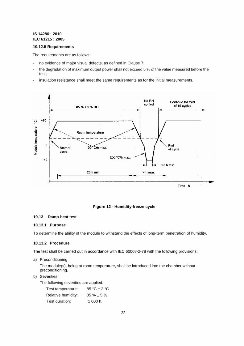
a) A climatic chamber with automatic temperature and humidity control, capable of subjecting one or more modules to the humidity-freeze cycle specified in Figure 12.
b) Means for mounting or supporting the module(s) in the chamber, so as to allow free circulation of the surrounding air. The thermal conduction of the mount or support shall be low, so that, for practical purposes, the module(s) is (are) thermally isolated.
c) Means for measuring and recording the module temperature to an accuracy of ±1 °C. (It is sufficient to monitor the temperature of one representative sample, if more than one module is being tested.)
d) Means for monitoring, throughout the test, the continuity of the internal circuit of each module.
10.12.3 Procedure
a) Attach a suitable temperature sensor to the front or back surface of the module(s) near the middle.
b) Install the module(s) at room temperature in the climatic chamber.
c) Connect the temperature monitoring equipment to the temperature sensor(s).
d) After closing the chamber, subject the module(s) to 10 complete cycles in accordance with the profile in Figure 12. The maximum and minimum temperatures shall be within ±2 °C of the specified levels and the relative humidity shall be maintained within ±5 % of the specified value at all temperatures above room temperature.
e) Throughout the test, record the module temperature.
10.12.4 Final measurements
After a recovery time between 2 h and 4 h, repeat the test of 10.3. Repeat the tests of 10.1 and 10.2.
31
IS 14286 : 2010 IEC 61215 : 2005
10.12.5 Requirements
The requirements are as follows:
- no evidence of major visual defects, as defined in Clause 7;
- the degradation of maximum output power shall not exceed 5 % of the value measured before the test;
- insulation resistance shall meet the same requirements as for the initial measurements.
Figure 12 - Humidity-freeze cycle
10.13 Damp-heat test
10.13.1 Purpose
To determine the ability of the module to withstand the effects of long-term penetration of humidity.
10.13.2 Procedure
The test shall be carried out in accordance with IEC 60068-2-78 with the following provisions:
a) Preconditioning
The module(s), being at room temperature, shall be introduced into the chamber without preconditioning.
b) Severities
The following severities are applied:
Test temperature: 85 °C ± 2 °C
Relative humidity: 85 % ± 5 %
Test duration: 1 000 h.
32

IS 14286 : 2010 IEC 61215 : 2005
10.13.3 Final measurements
After a recovery time between 2 h and 4 h, repeat the tests of 10.3 and 10.15. Repeat the tests of 10.1 and 10.2.
10.13.4 Requirements
The requirements are as follows:
- no evidence of major visual defects, as defined in Clause 7;
- the degradation of maximum output power shall not exceed 5 % of the value measured before the test;
- the insulation test and the wet leakage current test shall meet the same requirements as for the initial measurements.
10.14 Robustness of terminations test
10.14.1 Purpose
To determine that the terminations and the attachment of the terminations to the body of the module will withstand such stresses as are likely to be applied during normal assembly or handling operations.
10.14.2 Types of terminations
Three types of module terminations are considered:
- type A: wire or flying lead,
- type B: tags, threaded studs, screws, etc.;
- type C: connector.
10.14.3 Procedure
Preconditioning: 1 h at standard atmospheric conditions for measurement and test.
10.14.3.1 Type A terminations
Tensile test: as described in IEC 60068-2-21, test Ua, with the following provisions:
- all terminations shall be tested;
- tensile force shall never exceed the module weight.
Bending test: as described in IEC 60068-2-21, test Ub, with the following provisions:
- all terminations shall be tested;
- method 1-10 cycles (1 cycle is 1 bend in each opposite direction).
10.14.3.2 Type B terminations
Tensile and bending tests:
a) for modules with exposed terminals, each termination shall be tested as for type A terminations;
33

IS 14286 : 2010 IEC 61215 : 2005 b) if the terminations are enclosed in a protective box, the following procedure shall be applied:
- a cable of the size and type recommended by the module manufacturer, cut to a suitable length, shall be connected to the terminations inside the box using the manufacturer's recommended procedures. The cable shall be taken through the hole of the cable gland, taking care to utilize any cable clamp arrangement provided. The lid of the box shall be securely replaced. The module shall then be tested as for type A terminations.
Torque test: as described in IEC 60068-2-21, test Ud with the following provisions:
- all terminations shall be tested;
- severity 1.
The nuts or screws should be capable of being loosened afterwards unless they are specifically designed for permanent attachment.
10.14.3.3 Type C terminations
A cable of the size and type recommended by the module manufacturer, cut to a suitable length, shall be connected to the output end of the connector and the tests for type A terminations shall be carried out.
10.14.4 Final measurements
Repeat the tests of 10.1, 10.2 and 10.3.
10.14.5 Requirements
The requirements are as follows:
- no evidence of mechanical damage;
- the degradation of maximum output power shall not exceed 5 % of the value measured before the test;
- insulation resistance shall meet the same requirements as for the initial measurements.
10.15 Wet leakage current test
10.15.1 Purpose
To evaluate the insulation of the module under wet operating conditions and verify that moisture from rain, fog, dew or melted snow does not enter the active parts of the module circuitry, where it might cause corrosion, a ground fault or a safety hazard.
10.15.2 Apparatus
a) A shallow trough or tank of sufficient size to enable the module with frame to be placed in the solution in a flat, horizontal position. It shall contain a water/wetting agent solution meeting the following requirements:
Resistivity: 3 500 Q cm or less
Surface tension: 0,03 Nm-1 or less
Temperature: 22 °C + 3 °C
The depth of the solution shall be sufficient to cover all surfaces except junction box entries not designed for immersion.
34

IS 14286 : 2010 IEC 61215 : 2005
b) Spray equipment containing the same solution.
c) DC voltage source, with current limitation, capable of applying 500 V or the maximum rated system voltage of the module, whichever is more.
d) Instrument to measure insulation resistance.
10.15.3 Procedure
All connections shall be representative of the recommended field wiring installation and precautions shall be taken to ensure that leakage currents do not originate from the instrumentation wiring attached to the module.
a) Immerse the module in the tank of the required solution to a depth sufficient to cover all surfaces except junction box entries not designed for immersion. The cable entries shall be thoroughly sprayed with solution. If the module is provided with a mating connector, the connector should be immersed during the test.
b) Connect the shorted output terminals of the module to the positive terminal of the test equipment. Connect the liquid test solution to the negative terminal of the test equipment using a suitable metallic conductor.
c) Increase the voltage applied by the test equipment at a rate not to exceed 500 V s_1 to 500 V or the maximum system voltage for the module, whichever is greater. Maintain the voltage at this level for 2 min. Then determine the insulation resistance.
d) Reduce the applied voltage to zero and short-circuit the terminals of the test equipment to discharge the voltage build-up on the module.
10.15.4 Requirements
The requirements are as follows:
- For modules with an area of less than 0,1 m2 the insulation resistance shall be not less than 400 MQ.
- For modules with an area larger than 0,1 m2 the measured insulation resistance times the area of the module shall be not less than 40 MΩ.m2.
10.16 Mechanical load test
10.16.1 Purpose
The purpose of this test is to determine the ability of the module to withstand wind, snow, static or ice loads.
10.16.2 Apparatus
a) A rigid test base which enables the modules to be mounted front-side up or front-side down. The test base shall enable the module to deflect freely during the load application.
b) Instrumentation to monitor the electrical continuity of the module during the test.
c) Suitable weights or pressure means that enable the load to be applied in a gradual, uniform manner.
35
IS 14286 : 2010 IEC 61215 : 2005
10.16.3 Procedure
a) Equip the module so that the electrical continuity of the internal circuit can be monitored continuously during the test.
b) Mount the module on a rigid structure using the method prescribed by the manufacturer. (If there are different possibilities, use the worst one, where the distance between the fixing points is at maximum.)
c) On the front surface, apply gradually a load corresponding to 2 400 Pa, spread uniformly. (This load may be applied pneumatically or by means of weights covering the entire surface. In the latter case, the module shall be mounted horizontally.) Maintain this load for 1 h.
d) Apply the same procedure on the back surface of the module.
e) Repeat steps c) and d) for a total of three cycles.
NOTE 2 400 Pa corresponds to a wind pressure of 130 km-rr1 (approximately ±800 Pa) with a safety factor of 3 for gusty winds. If the module is to be qualified to withstand heavy accumulations of snow and ice. the load applied to the front of the module during the last cycle of this test is increased from 2 400 Pa to 5 400 Pa.
10.16.4 Final measurements
Repeat the tests of 10.1, 10.2 and 10.3.
10.16.5 Requirements
The requirements are as follows:
- no intermittent open-circuit fault detected during the test;
- no evidence of major visual defects, as defined in Clause 7;
- the degradation of maximum output power shall not exceed 5 % of the value measured before the test;
- insulation resistance shall meet the same requirements as for the initial measurements.
10.17 Hail test
10.17.1 Purpose
To verify that the module is capable of withstanding the impact of hailstones.
10.17.2 Apparatus
a) Moulds of suitable material for casting spherical ice balls of the required diameter. The standard diameter shall be 25 mm but any of the other diameters listed in Table 2 may be specified for special environments.
b) A freezer, controlled at -10 °C ± 5 °C.
c) A storage container for storing the ice balls at a temperature of -4 °C ± 2 "C.
d) A launcher capable of propelling an ice ball at the specified velocity, within ±5 %. so as to hit the module within the specified impact location. The path of the ice ball from the launcher to the module may be horizontal, vertical or at any intermediate angle, so long as the test requirements are met.
e) A rigid mount for supporting the test module by the method prescribed by the manufacturer, with the impact surface normal to the path of the projected ice ball.
36

IS 14286 : 2010 IEC 61215 : 2005
f) A balance for determining the mass of an ice ball to an accuracy of ±2 %.
g) An instrument for measuring the velocity of the ice ball to an accuracy of ±2 %. The velocity sensor shall be no more than 1 m from the surface of the test module.
As an example. Figure 13 shows in schematic form a suitable apparatus comprising a horizontal pneumatic launcher, a vertical module mount and a velocity meter which measures electronically the time it takes the ice ball to traverse the distance between two light beams. This is only one example as other types of apparatus including slingshots and spring driven testers have been successfully utilized.
Figure 13 - Hail-test equipment
Table 2 - Ice-ball masses and test velocities
Diameter mm
Mass g
Test velocity m s-1
Diameter mm
Mass g
Test velocity ms_t
12,5 0.94 16,0 45 43,9 30,7 15 1,63 17,8 55 80,2 33.9
25 7.53 23,0 65 132,0 36,7
35 20,7 27,2 75 203,0 39,5
37
IS 14286 : 2010 IEC 61215 : 2005
10.17.3 Procedure
a) Using the moulds and the freezer, make sufficient ice balls of the required size for the test, including some for the preliminary adjustment of the launcher.
b) Examine each one for cracks, size and mass. An acceptable ball shall meet the following criteria:
- no cracks visible to the unaided eye;
- diameter within ±5 % of that required;
- mass within ±5 % of the appropriate nominal value in Table 2.
c) Place the balls in the storage container and leave them there for at least 1 h before use.
d) Ensure that all surfaces of the launcher likely to be in contact with the ice balls are near room temperature.
e) Fire a number of trial shots at a simulated target in accordance with step g) below and adjust the launcher until the velocity of the ice ball, as measured with the velocity sensor in the prescribed position, is within ±5 % of the appropriate hailstone test velocity in Table 2.
f) Install the module at room temperature in the prescribed mount, with the impact surface normal to the path of the ice ball.
g) Take an ice ball from the storage container and place it in the launcher. Take aim at the first impact location specified in Table 3 and fire. The time between the removal of the ice ball from the container and impact on the module shall not exceed 60 s.
h) Inspect the module in the impact area for signs of damage and make a note of any visual effects of the shot. Errors of up to 10 mm from the specified location are acceptable.
i) If the module is undamaged, repeat steps g) and h) for all the other impact locations in Table 3, as illustrated in Figure 14.
Table 3 - Impact locations
Shot No. Location
1 A corner of the module window, not more than 50 mm from the frame
2 An edge of the module, not more than 12 mm from the frame
3,4 Over edges of cells, near an electrical joint
5,6 Over points of minimum spacing between cells
7,8 On the module window, not more than 12 mm from one of the points at which the module is fixed to the supporting structure
9,10 On the module window, at points farthest from the points selected above
11 Any points which may prove especially vulnerable to hail impact
38
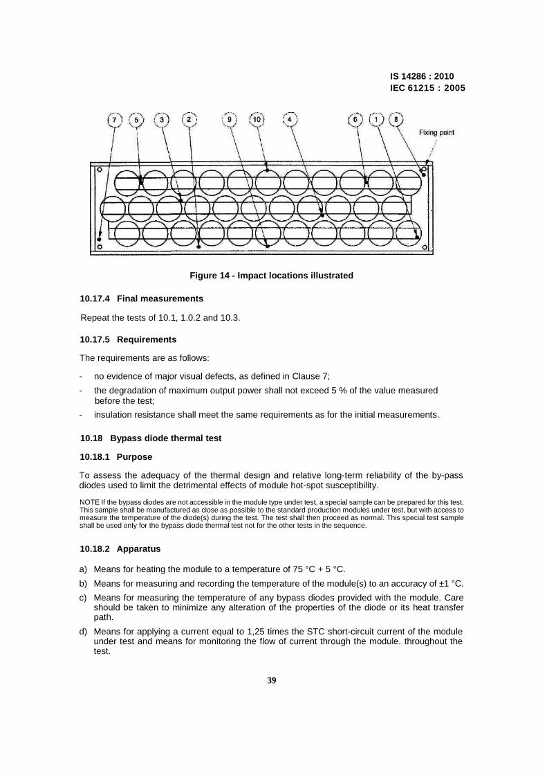
Figure 14 - Impact locations illustrated
10.17.4 Final measurements
Repeat the tests of 10.1, 1.0.2 and 10.3.
10.17.5 Requirements
The requirements are as follows:
- no evidence of major visual defects, as defined in Clause 7;
- the degradation of maximum output power shall not exceed 5 % of the value measured before the test;
- insulation resistance shall meet the same requirements as for the initial measurements.
10.18 Bypass diode thermal test
10.18.1 Purpose
To assess the adequacy of the thermal design and relative long-term reliability of the by-pass diodes used to limit the detrimental effects of module hot-spot susceptibility.
NOTE If the bypass diodes are not accessible in the module type under test, a special sample can be prepared for this test. This sample shall be manufactured as close as possible to the standard production modules under test, but with access to measure the temperature of the diode(s) during the test. The test shall then proceed as normal. This special test sample shall be used only for the bypass diode thermal test not for the other tests in the sequence.
10.18.2 Apparatus
a) Means for heating the module to a temperature of 75 °C + 5 °C.
b) Means for measuring and recording the temperature of the module(s) to an accuracy of ±1 °C.
c) Means for measuring the temperature of any bypass diodes provided with the module. Care should be taken to minimize any alteration of the properties of the diode or its heat transfer path.
d) Means for applying a current equal to 1,25 times the STC short-circuit current of the module under test and means for monitoring the flow of current through the module. throughout the test.
39
IS 14286 : 2010 IEC 61215 : 2005

IS 14286 : 2010 IEC 61215 : 2005
10.18.3 Procedure
a) Electrically short any blocking diodes incorporated in the module.
b) Determine the rated STC short-circuit current of the module from its label or instruction sheet.
c) Prepare to measure the temperature of the bypass diodes during the test.
d) Connect wires of the manufacturer's minimum recommended wire gauge to the output terminals of the module. Follow the manufacturer's recommendations for wire entry into the wiring compartment and replace the wire compartment cover.
NOTE Some modules have overlapping bypass diode circuits. In this case it may be necessary to install a jumper cable to assure that all of the current is flowing through one bypass diode.
e) Heat the module to 75 °C ± 5 °C. Apply a current to the module equal to the short circuit current of the module as measured at STC ± 2 %. After 1 h measure the temperature of each bypass diode. Using the information, provided by the diode manufacturer calculate the junction temperature from the measured case temperature and the power dissipated in the diode using the following formula.
Tj = Tcase + R THjc VD . ID
where
Tj is the diode junction temperature;
Tcase is the measure diode case temperature;
R THjc is the manufacturer's value relating junction temperature to case temperature;
VD is the diode voltage;
/D is the diode current. NOTE if the module contains a heat sink specifically designed to reduce the operating temperature of the diode, this test may be performed at the temperature the heat sink reaches under conditions of 1 000 W-rrr2 43 ;,C i3°C ambient with no wind rather than at 75 "C.
f) Increase the applied current to 1,25 times the short-circuit current of the module as measured at STC while maintaining the module temperature at 75 °C ± 5 °C. Maintain the current flow for 1 h.
g) Verify that the diode is still operational
NOTE Diode operation can be verified by using the subsequent hot spot test (10.9).
10.18.4 Final measurements
Repeat the tests of 10.1, 10.2 and 10.3.
10.18.5 Requirements
The requirements are as follows:
- the diode junction temperature as determined in 10.18.3.e) shall not exceed the diode manufacturer's maximum junction temperature rating;
- no evidence of major visual defects, as defined in Clause 7;
- the degradation of maximum output power shall not exceed 5 % of the value measured before the test;
- insulation resistance shall meet the same requirements as for the initial measurements;
- the diode shall still function as a diode after the conclusion of the test.
40
IS 14286 : 2010 IEC 61215 : 2005
Annex A (informative)
Changes in this second edition with respect to the first edition of IEC 61215
a) Subclause 10.15 (Twist test) has been deleted.
This test was originally developed to assure compliance with a JPL designed mounting system. Test labs report that no module type has ever failed.
b) A new subclause 10.15 (Wet leakage current test) has been included.
It is performed with the initial and final tests and within 2 h to 4 h of existing in the damp heat chamber.
This was a very important addition to IEC 61646. It identifies pin holes and small delimitations that cannot be seen by visual inspection.
c) A new subclause 10.18 has been added. (Bypass diode thermal test)
Field failures of bypass diodes are often associated with overheating. This test determines how hot the bypass diode is likely to get under worst case conditions and compares that temperature to the diodes temperature rating.
d) In Clause 8 (Report) requirements per ISO/IEC 17025 have been added.
e) Subclause 10.2 is now entitled Maximum power determination.
This allows the laboratory to select a set of conditions different from STC for the before and after measurements. This was done to increase repeatability and to minimize translation especially when measuring outdoors.
f) Subclause 10.3 (insulation test) has been modified so that the pass/faii criteria are to be dependent on the module area.
g) In 10.4, an outdoor method is now included and reference is made to IEC 60904-10.
h) In 10.5 the measurement of NOCT has been modified for clarification; a 45" tilt rather than latitude tat is to be used.
i) Subclause 10.6 is now entitled Performance at STC and NOCT since 10.2 is no longer restricted to STC.
j) Subclause 10.10 is now entitled UV preconditioning test.
The exposure levels originally utilized are used and not those specified in IEC 61345.
k) Subclause 10.11 (Thermal cycling test) and 10.12 (Humidity-freeze test) have been modified in order to eliminate the requirement to monitor for ground faults during the test. This was proposed by several test labs. They reported that this was a difficult requirement and that they had never observed a failure. It was felt that any short to ground would be observed in the subsequent dry insulation test or wet leakage current test.
I) Subclause 10.11 (Thermal cycling test) has been modified in order to add a requirement for running peak power current through the module, when the module is above room temperature. This procedure was adopted to simulate an actual field failure that was not identified by thermal cycling without current flow, but caused failures with current flow. This is a realistic test as the module will be carrying currents during most hot sunny days.
41
IS 14286 : 2010 IEC 61215 : 2005 m) Subclause 10.12 (Humidity-freeze test) has been modified in order to eliminate the two chamber
method. None of the major test labs are using a two chamber method and it was argued that the test severity would be considerably different if it were used.
n) Subclause 10.16 Mechanical load test) has been modified in order to add a third cycle and to clarify the optional testing to a higher, snow load. The additional cycle was added due to reports of module failures occurring in the third cycle, which is required by the ASTM mechanical load test.
42
GMGIPN—389 BIS/ND/2009—300
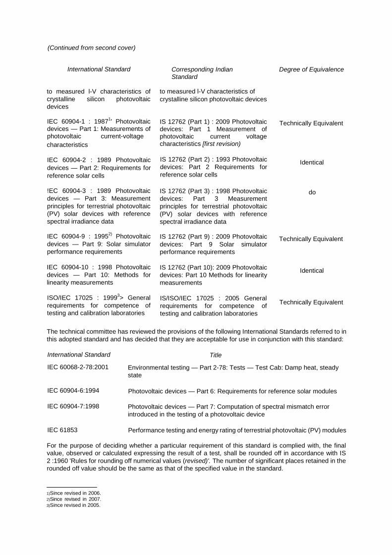
(Continued from second cover)
International Standard Corresponding Indian Standard
Degree of Equivalence
to measured l-V characteristics of crystalline silicon photovoltaic devices
to measured l-V characteristics of crystalline silicon photovoltaic devices
IEC 60904-1 : 19871' Photovoltaic devices — Part 1: Measurements of photovoltaic current-voltage characteristics
IEC 60904-2 : 1989 Photovoltaic devices — Part 2: Requirements for reference solar cells
IS 12762 (Part 1) : 2009 Photovoltaic devices: Part 1 Measurement of photovoltaic current voltage characteristics [first revision)
IS 12762 (Part 2) : 1993 Photovoltaic devices: Part 2 Requirements for reference solar cells
Technically Equivalent
Identical
!EC 60904-3 : 1989 Photovoltaic devices — Part 3: Measurement principles for terrestrial photovoltaic (PV) solar devices with reference spectral irradiance data
IEC 60904-9 : 19952) Photovoltaic devices — Part 9: Solar simulator performance requirements
IEC 60904-10 : 1998 Photovoltaic devices — Part 10: Methods for linearity measurements
ISO/IEC 17025 : 19993> General requirements for competence of testing and calibration laboratories
IS 12762 (Part 3) : 1998 Photovoltaic devices: Part 3 Measurement principles for terrestrial photovoltaic (PV) solar devices with reference spectral irradiance data
IS 12762 (Part 9) : 2009 Photovoltaic devices: Part 9 Solar simulator performance requirements
IS 12762 (Part 10): 2009 Photovoltaic devices: Part 10 Methods for linearity measurements
IS/ISO/IEC 17025 : 2005 General requirements for competence of testing and calibration laboratories
do
Technically Equivalent
Identical
Technically Equivalent
The technical committee has reviewed the provisions of the following International Standards referred to in this adopted standard and has decided that they are acceptable for use in conjunction with this standard:
International Standard
IEC 60068-2-78:2001
Title
Environmental testing — Part 2-78: Tests — Test Cab: Damp heat, steady state
IEC 60904-6:1994
IEC 60904-7:1998
IEC 61853
Photovoltaic devices — Part 6: Requirements for reference solar modules
Photovoltaic devices — Part 7: Computation of spectral mismatch error introduced in the testing of a photovoltaic device
Performance testing and energy rating of terrestrial photovoltaic (PV) modules
For the purpose of deciding whether a particular requirement of this standard is complied with, the final value, observed or calculated expressing the result of a test, shall be rounded off in accordance with IS 2 :1960 'Rules for rounding off numerical values (revised)'. The number of significant places retained in the rounded off value should be the same as that of the specified value in the standard. 1)Since revised in 2006. 2)Since revised in 2007. 3)Since revised in 2005.

Bureau of Indian Standards
BIS is a statutory institution established under the Bureau of Indian Standards Act, 1986 to promote harmonious development of the activities of standardization, marking and quality certification of goods and attending to connected matters in the country.
Copyright
BIS has the copyright of all its publications. No part of the these publications may be reproduced in any form without the prior permission in writing of BIS. This does not preclude the free use, in the course of implementing the standard, of necessary details, such as symbols and sizes, type or grade designations. Enquiries relating to copyright be addressed to the Director (Publications), BIS.
Review of Indian Standards
Amendments are issued to standards as the need arises on the basis of comments. Standards are also reviewed periodically; a standard alongwith amendments is reaffirmed when such review indicates that no changes are needed; if the review indicates that changes are needed, it is taken up for revision. Users of Indian Standards should ascertain that they are in possession of the latest amendments or edition by referring to the latest issue of 'BIS Catalogue' and 'Standards: Monthly Additions'.
This Indian Standard has been developed from Doc No.: ETD 28 (6015).
Amendments Issued Since Publication