is 1293 (2005): plugs and socket- outlets of rated voltage...
TRANSCRIPT

Disclosure to Promote the Right To Information
Whereas the Parliament of India has set out to provide a practical regime of right to information for citizens to secure access to information under the control of public authorities, in order to promote transparency and accountability in the working of every public authority, and whereas the attached publication of the Bureau of Indian Standards is of particular interest to the public, particularly disadvantaged communities and those engaged in the pursuit of education and knowledge, the attached public safety standard is made available to promote the timely dissemination of this information in an accurate manner to the public.
इंटरनेट मानक
“!ान $ एक न' भारत का +नम-ण”Satyanarayan Gangaram Pitroda
“Invent a New India Using Knowledge”
“प0रा1 को छोड न' 5 तरफ”Jawaharlal Nehru
“Step Out From the Old to the New”
“जान1 का अ+धकार, जी1 का अ+धकार”Mazdoor Kisan Shakti Sangathan
“The Right to Information, The Right to Live”
“!ान एक ऐसा खजाना > जो कभी च0राया नहB जा सकता है”Bhartṛhari—Nītiśatakam
“Knowledge is such a treasure which cannot be stolen”
“Invent a New India Using Knowledge”
है”ह”ह
IS 1293 (2005): Plugs and socket- outlets of rated voltageup to and including 250 volts and rated current up to 16amperes [ETD 14: Electrical Wiring Accessories]


IS 1293:2005
W?dh7WmF
,250dTFt Tl@#lif%dRWH%?k
(i%?iw pi%=Fl)
Indian Standard
PLUGS AND SOCKET-OUTLETS OF RATEDVOLTAGE UP TO AND INCLUDING
250 VOLTS AND RATED CURRENT UP TO ANDINCLUDING 16 AMPERES — SPECIFICATION
( Third Revision)
ICS 29.120.30
t
0 BIS 2005
BUREAU OF INDIAN STANDARDSMANAK BHAVAN, 9 BAHADUR SHAH ZAFAR MARG
NEW DELHI 110002
October 2005 Price Group 17 J
P---’”
Electrical Wking Accessories Sectional Committee, ETD 14
FOREWORD
This Indian Standard (Third Revision) was adopted by the Bureau of Indian Standards, after the draft finalizedby the Electrical Wiring Accessories Sectional Committee had been approved by the Electrotechnical Division
‘4
Council.
This standard was first published in 1958. The first revision was brought out in 1967 and the second revision wasbrought out in 1988. This revision has been undertaken to bring it in line with latest International practices. Thisstandard covers the requirements and test methods for plugs and fixed or portable socket-outlets for ac and withand without earthing contact with a rated voltage above 50 V, but not exceeding 250 V and a rated current not
I
exceeding 16A intended for household and similar purposes for indoors and outdoors. This standard also coversplugs incorporated in cord sets and to plugs and portable socket-outlets incorporated in coqd extension sets.
In view of greater prevalence of the use of two pin plugs and socket-outlets in every household, it has becomenecessary to standardize such plugs. However the user must ensure proper earthing practices in their installation
/
?,
in line with IS 732 : 1989 ‘Code of practice for electrical wiring installations’ and IS 3043 : 1987 ‘Code of.,
practice for earthing’. Two pin plugs are intended to be used only for class II appliances. :/:’
This standard is based on IEC 60884-1 (2002) ‘Plugs and socket outlet for household and similar purposes —Part 1 : General requirements’, issued by the International Electrotechnical Commission except for followingmodifications: L
a) Accessories ratings covered are only up to and including 16A and 250 V.
b) Combined socket-outlet has been covered.
c) Ambient test condition.
d) Schedule of routine, acceptance and @e tests have been included.
e) Rated voltage covered up to and including 250 V.
The test methods are technically equivalent to corresponding ISO/IEC publications as stated below:
Title/Clause IS No. ISO/IECRe$ of the Test
Clause 9 to 30 1293:2005 IEC 60884-1 (2002)
Damp heat cycling test 9000 (Part 5/See 1 & 2): 1981 IEC 60068-2-30 (1980)
Glow wire test 11000 (Part 2/See 1) :1984 IEC 60068-2-1 (1980)
Electroplated coating of nickel 1068:1993 1S0 1456:1988plus chromium and of copperplus nickel plus chromium
Electroplated coating of tin 1359:1992 IS@093 :1986
Electroplated coating of Zinc 1573:1986 1S0’2081 :1986on iron and steel
After the publication of this standard IS 6538:1971 ‘Specification for three-pin plugs made of resilient material’shall be withdrawn since the requirements have been covered in this standard. #
For the purpose of deciding whether a particular requirement of this standard is complied with, the final value,observed or calculated, expressing the result of a test or analysis, shall be rounded off in accordance with1S 2: 1960 ‘Rules of rounding off numerical values (revised’. The number of significant places retained in therounded off value should be the same as that of the specified value in this standard.
.
IS 1293:2005,..
,,,,
Indian Standard
PLUGS AND SOCKET-OUTLETS OF RATEDVOLTAGE UP TO AND INCLUDING
250 VOLTS AND RATED CURRENT UP TO ANDINCLUDING 16 AMPERES — SPECIFICATION
( Third Revision)
1 SCOPE
1.1 This standard applies to plugs and fixed or portablesocket-outlets for ac only, with and without earthingcontact, with a rated voltage above 50 V but notexceeding 250 V and a rated current not exceeding16A. intended for household and similar purposes,either indoors or outdoors.
This standard does not cover requirement for flushmounting boxes, however it covers only thoserequirements for surface-type mounting boxes whichare necessary for the tests on the socket-outlet.
NOTES
1 Requirements for mounting boxes are given inIS 14772.
This standard applies also to plugs incorporated in cord setsand to plugs and portable socket-outlets incorporated in cordextension sets. It also applies to plugs and socket-outletswhichare a component of an appliance, unless otherwise stated in thestandard for the relevant appliance,
2 Particular requirements are under consideration for
a) Adaptors;
b) Fused plugs;
c) Cable reels; and
d) Plugs, fixed and portable socket-outlets for extra lowvoltage (ELV) and safety extra low voltage (SELV).
This standard does not apply to:
a) Plugs, socket-outlets and couplers for industrialpurposes;
b) Appliance couplers;
c) Fixed socket-outlets combined with fuses, automaticswitches, etc; and
d) Plugs, fixed and portable socket-outlets for ELV,
3 Socket-outlets with pilots lights are allowed provided thatpilot light comply with the relevant standard, if arty.
Plugs and fixed or portable socket-outlets complying with thisstandard are suitable for use at ambient temperatures notnormally exceeding 35°C but occasional y reaching 45”C.
4 Socket-outJetscomplyingwith this standardareonly suitablefor incorporation in equipment in such a way and in such aplace that it is unlikely that the ambient surroundingthe socket-outlet reaches a temperature exceeding 45”C.
In locations where special conditions prevail, as .in ships,vehicles and the like, and in hazardous locations, for example,where explosions are liable to occur, special constructions maybe required.
2 REFERENCES
2.1 The following standards are necessary adjuncts tothis standard:
1S No.
292:1983
694:1990
1068:1993
1359:
1573:
992
986
2824:1975
3010
(Part 1): 1965
(Part 2): 1965
9000 (Part 5/See 1and2) :1981
Title
Leaded brass ingots and casting(second revision)
PVC insulated cables for ~, ~],
working voltages up to andti1?:., f
including 1 100 V (third revision) ~d;
Electroplated coatings of nickelplus chromium and copper plusnickel plus chromium (third .
revision) $‘i,,,’,’
Electroplated coating of tin (third ‘@
revision)
Electroplated coating of zinc on ‘1iron and steel (second revision)
Method for determining thecomparative tracking index ofsolid insulating materials undermoist conditions (first revision)
Appliances connectors and.
flappliance-inlets (non-reversiblethree pin type): %
Appliances connectors
Appliances inlet
Basic environmental testingprocedures for electronic and
electrical items : Part 5 Dampheat cycling test, Section 1, 16+8 h cycle, Section 2, 12 + 12 hcycle
9968 (Part 1) :1988 Elastomer-insulated cables:Part 1 For working voltages upto and including 1 100 V (firstrevision)
11000 (Part 2/ Fire hazard testing: Part 2 TestSec 1) :1984 method, Section 1 Glow wire test
and guidance
1
.
IS 1293:2005
IS No.
12063:1987
14340:1996
14772:2000
Title
Classification of degree ofprotection provided byenclosures of electricalequipment
Brass for current-carrying partsin electrical wiring accessories
General requirements forenclosures for accessories forhousehold and similar fixedelectrical installations
3 TERMINOLOGY
The following definitions shall apply for the purposeof this standard.
(The use of the accessories is shown in Fig. 1A).
3.1 Plug — Accessory having pins designed to engagewith the contacts of a socket-outlet, also incorporatingmeans for the electrical connection and mechanicalretention of flexible cable(s).
3.2 Socket-Outlet — Accessory having socket-contacts designed to engage with the pins of a plugand having terminals for the connection of cable(s).
3.3 Fixed Socket-Outlet — A socket-outlet which isintended to be connected to the fixed wiring.
3.4 Portable Socket-Outlet — Socket-outlet whichis intended to be connected to, or integral with, flexiblecables, and which can easily be moved from one placeto another while connected to the supply.
3.5 Multiple Socket-Outlet — Combination of twoor more socket-outlets. (Example of portable multiplesocket-outlet is shown in Fig. lB).
3.6 Combined Socket-Outlets — A socket assemblywith provision of plugging two or more types or ratingof plugs but in which only one or two plugs can beplugged in at a time. (Typical examples of combinedsocket-outlets are shown in Fig 1C).
3.7 Socket-Outlet for Appliances — Socket-outletintended to be built in or fixed to appliances.
3.8 Rewirable Plug or Rewirable Portable Socket-Outlet — Accessory so constructed that the flexiblecable can be replaced.
3.9 Non-rewirable Plug or Non-rewirable PortableSocket-Outlet
Accessory so constructed that it forms a complete unitwith the flexible cable after connection and assemblyby the manufacturer of the accessory (see also 14.1).
3.10 Moulded-on Accessory — Non-rewirableaccessory the manufacture of which is completed byinsulating material moulded around pre-assembled
component parts and the terminations of the flexiblecable.
3.11 Mounting Box — Box intended for mounting inor on a wall, floor or ceiling etc, for flush or surfaceapplication, intended for use with a fixed socket-outlet(s). A
3.12 Cord Set — Assembly consisting of a flexiblecable fitted with a non-rewirable plug and a non-rewirable connector, intended for the connection ofan electrical appliance to the electrical supply.(Example of cord set is shown in Fig 1A). I
3.13 Cord Extension Set — Assembly consisting ofa flexible cable fitted with a non-rewirable plug and anon-rewirable portable socket-outlet. (Example of cord /extension set is shown in Fig 1A). f “
3.14 Terminal — insulated or non-insulated
)“
“,
connecting device serving for reusable electricalconnection of the external conductors.
t,
3.15 Termination — Insulated or non-insulatedconnecting device intended for non-reusable electrical ‘-%connection of the external conductors.
3.16 Clamping Unit — Part or parts of a terminalnecessary for the mechanical clamping and theelectrical connection of the conductor(s).
3.17 Screw-Type Terminal — Terminal for theconnection a;~ subsequent disconnection of aconductor or the interconnection of two or moreconductors capable of being dismantled, theconnection being made, directly or indirectly, by
k
means of screws or nuts of any kind.
3.17.1 Pillar Terminal — Screw-type terminal in ,;
which the conductor is inserted into a hole or cavity,where it is clamped under the shank of the screw orscrews. The clamping pressure may be applied directly .by the shank of the screw or through an intermediatemember to which presstme is applied by the shank ofthe screw. (Example of pillar terminals is given in %
Fig. 34.)
3.17.2 Screw Terminal — Screw-type terminal inwhich the conductor is clamped under the head of the t
screw. The clamping pressure may be applied directlyby the head of the screw or through an intermediatepart, such as a washer, clamping plate or anti-spreaddevice. (Example of screw terminals is given in
~
Fig. 35.)
3.17.3 Stud Terminal — Screw-type terminal inwhich the conductor is clamped under a nut, Theclamping pressure may be applied directly by a suitablyshaped nut or through an intermediate part, such as awasher, clamping plate or anti-spread device.(Examp~e of stud terminals is given in Fig. 35.)
3.17.4 Saddle Terminal — Screw-type terminal in
2
N..,...
which the conductor clamped under a saddle by meansof two or more screws or nuts. (Example of saddleterminals are given in Fig. 36.)
3.17.5 Mantle Terminal — Screw-type terminal inwhich the conductor is clamped against the base of aslot in a threaded stud by means of a nut. The conductoris clamped against the base of the slot by a suitablyshaped washer under the nut, by a central peg if thenut is a cap nut, or by equally effective means fortransmitting the pressure horn the nut to the conductorwithin the slot. (Example of mantle terminals is givenin Fig. 37.)
3.18 Screwless Terminal — Connecting device forthe connection and subsequent disconnection of oneconductor or the dismountable interconnection of twoor more conductors capable of being dismantled, theconnection being made, directly or indirectly, bymeans of springs, wedges, eccentrics or cones, etc,without special preparation of the conductorconcerned, other than removal of insulation.
3.19 Rated Voltage — Voltage assigned to the plugor socket-outlet by the manufacturer.
3.20 Rated Current — Current assigned to the plugor socket-outlet by the manufacturer.
3.21 Shutter — Movable part incorporated into asocket-outlet arranged to shield at least the live socket-outlet contacts automatically when the plug iswithdrawn.
3.22 Thread-Forming Screw — Tapping screwhaving an uninterrupted thread, which by screwingin, forms a thread by displacing material. (Exampleof a thread-forming screw is shown in Fig. 38.)
3.23 Thread-Cutting Screw— Tapping screw havingan interrupted thread, which by screwing in, makesthread by removing material. (Example of thread-cutting tapping screw in Fig. 39.)
3.24 Type Test —Tests carried out to proveconformity with the requirement of the specification.These are intended to prove the general qualities anddesign of the given type of plug or socket-outlets.
3.25 Acceptance Test — Test carried out on samplestaken from a lot for the purpose of acceptance of thelot.
3.26 Routine Test —Test carried out on each itemto check requirements which are likely to vary duringproduction.
3.27 Class I Appliances — An appliance in whichprotection against electric shock does not rely on basicinsulation only, but which includes an additional safetyprecaution in that accessible conductive parts areconnected to the protective earthing conductor in thefixed wiring of the installation in such a way that
IS 1293:2005
accessible conductive parts cannot become live in theevent of a failure of the basic insulations.
3.28 Class II Appliances — An appliance in whichprotection against electric shock does not rely on basicinsulation, only, but in which additional safetyprecautions, such as, double insulation or reinforcedinsulation are provided, there being no provision forprotective earthing or reliance upon installationcondition.
3.29 Safety Extra Low Voltage (SELV)’-A nominalvoltage not exceeding 32 V between conductors andbetween conductors and earth or, for three phasesupply, not exceeding 18.5 V between conductors, andthe no-load voltage not exceeding 38 V and 22 Vrespectively.
3.30 Crimp Type Terminal — Termination havingthe means of permanent connection made by crimpingthe part of terminal itself. It may also be made out ofsheet metal or solid metal.
NOTES
1 Wherethe termsvoltage and currentarc used in thk standard,they imply rms vatues, unless otherwise specified.
2 Throughout thk stsndard the word esrthing is used forprotective eartldng.
3 The term sceessory is used ss a genersdterm covering plugsand socket-outlets; the term portable accessory covers plugsand portable socket-outlets.
4 Through-outttds standardthe term socket-outtet covers bothfixed and portsble socket-outlets, except where the referenceis specific to one type or the other.
4 GENERAL REQUIREMENT
4.1 Accessories and surface type mounting boxes shallbe so designed and constructed that in normal use theirperformance is reliable and without danger to the useror surroundings. In general, compliance is checked bycarrying out all the relevant test specified.
5 GENERAL NOTES ON TESTS
5.1 Tests according to this standard are type tests.
5.1.1 Schedule of routine, acceptance and type testsare given in 31.
5.2 Unless otherwise specified, the specimens aretested as delivered and under normal conditions of use.
Non-rewirable accessories are tested with the type andsize of flexible cable as delivered; those notincorporated in a cord set or a cord extension set orwhich are not a component of equipments shall beprovided for testing, with at least 1 m of flexible cableof relevant specification.
Non-rewirable multiple portable socket-outlets aretested with flexible cables having a length of about2.5 m.
Socket-outlet which does not comply with any
3

IS 1293:2005
accepted standard dimensions specified in this standardare tested together with their corresponding boxes.
Socket-outlets, which require a box to complete theirenclosure, are tested with their boxes.
5.3 Unless otherwise specified the tests are carried outin the order of the clauses, at an ambient temperaturebetween 15°C and 35°C. In case of doubt the test aremade at an ambient temperature of 27 * 5°C.
Plugs and socket-outlets are tested separately.
The neutral, if any, is treated as a pole.
5.4 Three samples are subjected to all the relevanttests.
For the tests of Screwless Terminals for ExternalConductor (see 12.3.1 1) additional samples of socket-outlets having in total at least 5 screwless terminalsare required.
For the test of Screwless Terminals for ExternalConductor (see 12.3.12), three additional samples ofsocket-outlets are necessary: in each sample oneclamping unit is tested.
For each of the tests of construction of fixed socket-outlet (see 13.22 and 13.23), three additional samplesof separate membranes, or of accessories incorporatingmembranes, are required.
For non-rewirable accessories, six additional samplesare required for the tests of Flexible Cable and theirconnection (see 23.2 and 23.4).
For the test of Mechanical Strength (see 24.10), threeadditional samples are required.
For the test of Resistance of Insulating Material toAbnormal Heat, to Fire and to Tracking (see 28), threeadditional samples may be necessary.
5.5 Accessories are deemed not to comply with thisstandard if there are more failures than that of onesample in one of the tests.
If one sample fails in a test, that test and thosepreceding, which may have influenced the result ofthat test, are repeated on another set of samples of thenumber specified in 5.4, all of which shall then complywith the repeated tests.
NOTES
1 In generrd,it will only be necessaryto repeat the tests whichcaused the failure, unless the sample fails in one of the tests of20 to 22 inclusive, in which case the tests are repeated tlomthat of 19onwards.
2 The manufacturermay submit together with the number ofsamples specified in 5.4, the additional set of samples whichmay be needed should one sample fail. The testing authoritywill then, without finther request test the addltionat samplesand will only reject if a firrther faihsre occurs. If the additionalset of samples is not submitted at the same time, a failure ofone sample will entail a rejection.
6 RATINGS
6.1 Accessories shall preferably be of a type andpreferably have voltage and current ratings as shownin Table 1.
6.2 In a cord extension set, the rated current of theportable socket outlet shall be not higher and the ratedvoltage shall be not less than that of the plug.
Compliance is checked by inspection of the marking.
An example of cord extension set is shown in Fig. 1A.
7 CLASSIFICATION
7.1 Accessories are Classified
7.1.1 According to the degree of protection againstharmful ingress of wate~
—
—
Table 1 Preferred Combination
ordinary accessories, that is with degree ofprotection not higher than IPXO or IPX1, whenmounted on a vertical surface as for normal use,
NOTE — For the purpose of ttds standard the term ordinaryapplies only to the degree of protection against harmful ingressof water.
Splash-proof accessories, that is with-degree ofprotection IPX4, and
of Types and Ratings
(Clause 6.1)
Type Rated Voltage Rated Currentv A
(1) (2) (3)
2 pole (non-rewirable plugs only) 230,240 and 250 2.5
2 pole (plugs only) 230,240 and 250 6
2 pole + ~ 230,240 and 250 61)
1016
NOTE — Standardized dimensions of the plugs and socket-outlet are given in Annex A.
I) Intem~tionalpracticesprovidefor 10Aso~ket.outle~ for ~] app]i~ces ~quiringUpto ad including10Awhereas in Indi&the socket
of 6A is still in use. The manufacturer would develop 10Asocket-outlets with the same physicrddimensions as of the present 6A socket-outlets. After satisfactory development of 10Asocket-outlets, the 6A socket-outlets are to be phased out in tirture.
4
— Jet-proof accessories, that is with degree ofprotection IPX5.
7.1.2 According to the provision for earthing:
a) Accessories without earthing contact; and
b) Accessories with earthing contact.
7.1.3 According to the method of connecting thecable:
a) Rewirable accessories; and
b) Non-rewirable accessories.
7.1.4 According to the type of terminals:
a) Accessories with screw-type terminals;
b) Accessories with screwless terminals for rigidconductors only; and
c) Accessories with screwless terminals for rigidand flexible conductors.
7.2 Socket-Outlets are Classified
7.2.1 According to the degree of protection againstelectric shock when mounted as for normal use:
a) With normal protection (see 10.1); and
b) With increased protection (see 10.7).
NOTE — Socket-outlets with increased protection may besocket-outlet with or without shutters.
7.2.2 According to the existence of enclosures:
a) Unenclosed; and
b) Enclosed.
NOTE — For unenclosed socket-outlets, the protection againstelectric shock is given by the enclosure in which the socket-outlet is intended to be mounted.
7,2.3 According to the existence of shutters:
a) Without shutters; and
b) With shutters (see 10.5).
7.2.4 According to the method of applicationmounting of the socket-outlet:
a) Surface-type;
b) Flush-type;
c) Semi-flush type;
d) Panel-type;
e) Architrave-type;
f) Portable-type;
g) Table-type (single or multiple);
h) Floor recessed type; and
j) Appliances type.
7.2.5 According to the method of installation, as aconsequence of the design:
a) Fixed socket-outlets where the cover or cover-plate or parts of them can be removed without
IS 1293:2005
displacement of the conductors (design A); and
b) Fixed socket-outlets where the cover or cover-plate or parts of them cannot be removedwithout displacement of the conductors(design B).
NOTE — If a fixed socket-outlet has a base (main part) whichcannot be separated from the cover or cover-pIate, and requiresa supplementary plate which can be removed for redecoratingthe wall without displacementof the conductors, it is consideredto be of design A, provided the supplementary plate meets therequirements specified for covers and cover-plates.
7.3 Plugs are classified according to the class ofappliances to which they are intended to be connected:
a) Plugs for appliances of Class 1; and
b) Plugs for appliances of Class II.
8 MARKING
8.1 Accessories shall be marked with:
a) Rated current, in amperes;
b) Rated voltage, in volts;
c) Symbol for nature of supply;
d) Manufacture or responsible vendor’s name,trade-mark or identification mark;
e) Type reference, which may be a cataloguenumber;
f) Symbol for degree of protection against ingressof solid foreign bodies, if higher than IP2x;
g) Country of manufacture; and
h) Symbol for degree of protection against harmtilingress of water, if applicable, in which casethe symbol for degree of protection againstingress of solid foreign bodies shall be markedeven, if not higher than IP2X.
If the system allows plugs of a certain 1P ratings to beintroduced into socket-outlets having another 1P rating,attention shall be drawn to the fact that the resultingdegree of protection of the combination plugfsocket-outlet is the lower of the two. They shall be stated inthe manufacturer’s literature related to the socket-outlet.
NOTE — The degree of protection are based on IS 12063.
In addition, socket-outlets with screwless terminalsshall be marked with:
— an appropriate marking indicating the length ofinsulation to be removed before the insertion ofthe conductor into the screwless terminal; and
— an indication of the suitability to accept rigidconductors only, for those socket-outlets havingthis restriction.
NOTES
1 The additional markings maybe put on the socket-outlet,on the packagingunit and/orgiven in an inshuction sheet which
P,,.,..,’. ‘+
;,),
‘l
,.
,
5
IS 1293:2005
8.2
accompanies the socket-outlet.
2 Fortwopin (twopole)plugsfollowing information shaUbegiven on the cartons:
“Plugs of two poles are suitable for class II appliances only.”
When symbols are used, they shall be as follows:
—
—
—
—
—
—
—
—
amperes . . . . . . . . . . . . . . . . . . . . . . . . . . . . . . . . . . . . ..A
volts . . . . . . . . . . . . . . . . . . . . . . . . . . . . . . . . . . . . . . . . ..V
alternating current . . . . . . . . . . . . . . . . . . . . . . . . ...-
neutral . . . . . . . . . . . . . . . . . . . . . . . . . . . . . . . . . . . . . . ..N
earth . . . . . . . ... . . . . . . . . . . . . . . . . . . . . . . . . . . . . . . . . . A
splash-proof construction . . . . . . . . . . . . ..IPX4
jet-proof construction . . . . . . . . . . . . . . . . . . .IPX5
terminal for line (live) . . . . . . . . . . . . . . . . . ..L
NOTES
1 Lines formed by the construction of the tools are notconsidered as part of the mssrkhg.
2 In the 1Pcode the letter “X concerningprotectionagainstingressof solid objects shall be replacedbythe relevantnumber.
3 Ordinary accessories are not msrked with any symbol forprotection against harmful ingress of water.
For the marking with rated current and rated voltage,figures may be used alone. These figures shall beplaced on one line separated by an oblique line or thefigure for rated current shall be placed above the figurefor rated voltage, separated by a horizontal line.
The marking for nature of supply shall be placed nextto the marking for rated current and rated voltage.
NOTE—Themarkhg forcurren~ vohage and natureof supplymay be, for example, as follows:
16 A250V - or 16/’250- or 161250-
8.3 For fixed socket-outlets the marking with ratedcurrent, rated voltage and nature of supply, either thename, trade-mark or identification mark of themanufacturer or of the responsible vendor and the typereference shall be on the main part.
NOTE— Thetypereference maybe the series referencesonly.
Parts such as cover-plates, which are necessary forsafety, purposes and are intended to be sold separately,shall be, marked with either the name, trade-mark oridentification mark of the manufacturer or of theresponsible vendor and the type reference.
The symbol for degree of protection against harmfilingress of water, if applicable, shall be marked on theoutside of its associated enclosure so as to be easilydiscernible when the socket-outlet is mounted andwired as for normal use.
NOTES
1 Additional type referencesmaybe marked on the main pastor on the outside or inside of the associated enclosure.
6
2 The term “main part” means the part carrying the socketwrntacts.
8.4 For plugs and portable socket-outlets, the markingspecified in 8.1, other than the type reference, shallbe easily discernible when the accessory is wired andassembled.
Plugs and portable socket-outlets for equipments ofclass II shall not be marked with the symbol for class11construction.
NOTE — The type referenw. of rewirable accessories may bemarked on the inside of the enclosure or cover.
8.5 Terminals intended exclusively for the neutralconductor shall be indicated by the’ letter N. Earthingterminals shall be indicated by the symbol ‘ A‘.
The marking shall not be placed on screws, or any
/
.
other easily removable parts.
Terminals provided for the connection of conductors,
Fnot forming part of the main fimction of the socket- /outlet shall be clearly identified unless their purpose !
is self-evident, or indicated in a wiring diagram which Lshall be f~ed to the accessory.
The identification of accessory terminals may beachieved by:
— their marking with graphical symbols or coloursandfor,
— alpha-numeric system, or
— their physical dimensions or relative location.
Leads of neons or indicator lamps are not consideredto be conductors for the purpose of this sub-clause.
NOTES
1 “Easily removable parts” are those parts which csrs beremoved during the normal installation of the socket-outlet orthe assembly of the plug.
2 Terminationin non-rewirable need not be marked.
8.6 Fixed socket-outlets other than ordinary shall bemarked with the symbol for the degree of protectionagainst harrnfi.d ingress of water so that it is visiblewhen the accessory is installed. For surface typemounting boxes, the marking may be made onboxes forming an integral part of the socket-outlet,provided the symbol is visible when the accessory isinstalled.
Compliance is checked by inspection.
8.7 Marking shall be durable and easily legible.
Compliance is checked by inspection and by thefollowing testi
“The marking is rubbed by hand for 15s with a pieceof cloth socked with water and again for 15 s with apiece of cloth soaked with petroleum spirit”.
IS 1293:2005
,T -
P.,.,
!.
,.!~
,.
NOTES
1 Marking made by impressio~ mordding, pressing orengraving is not subjected to ttds test.
2 It isrccommendedthat thepetrolemnspirit rrsedconsistofa solvent hexane with an aromatic content of maximum 0.1percentage by volume, a kauributanol value of 29, an initirdboiling point of approximately 65”C, a dry point ofapproximately 69°C and a specific density of approximately0.68 g/cm].
8.8 The accessories may also be marked with theStandard Mark.
8.8.1 The use of the Standard Mark is governed bythe provision of Bureau ofIndian Stan&r&Act, 1986and the Rules and Regulations made thereunder. Thedetails of conditions under which the license forthe use of the Standard Mark maybe granted to themanufacturers or the producers maybe obtained fromthe Bureau of Indian Standards.
9 CHECKING OF DIMENSIONS
9.1 Plugs and socket-outlets shall comply with theappropriate gauge (see Annex B). The dimensions ofplugs and socket-outlets are given in Annex A.
Insertion of plugs into f~ed or portable socket-outletshall be ensured by their compliance with the relevantgauges.
Compliance is checked by measurement and/or bymeans of gauges. The manufacturing tolerances ofthese gauges shall be as shown in Table 2, if nototherwise, specified, The most unfavorabledimensions shall be used for the design of the gauges.
NOTE — In some cases (for example, distances betweencentres), it might be necessary to check both the extremedimensions.
Socket-outlets are subjected, before the above
Table 2 Gauge Tolerances
(Clause 9.1)
S1No. Gauge for Checking Gauge Tolerancemm
(1) (2) (3)
i) Pin diameter o-0.01
ii) Dimension of entry holes corres- + r).olpending to pin diameter and to odistance be~een contact surfaces
iii) Pin length and width o0.1
iv) Pin spacing (according to the case) o + 0.2-0.2 or O
v) Distance from engagement face to o + 0.05point of first touch of socket -0.05 or Ocontact(accordingto the case)
vi) Guiding elements * 0.03
checking, to ten insertions and ten withdrawals of aplug complying with the corresponding plugs as givenin Annex A having the maximum dimensions for thepins.
9.2 It shall not be possible, within a given system, toengage a plug with:
a) Socket-outlet having a higher voltage rating ora lower current rating; and
b) Socket-outlet with a different number of livepoles; exceptions may be admitted for socket-outlets which are specially constructed for thepurpose to allow engagement with plugs of alower number of poles, provided that nodangerous situation can arise, for example, aconnection between a live pole and an earthingcontact or the interruption of the earthing circuit.
It shall not be possible to engage a plug for applianceof Class I with a socket-outlet exclusively designed toaccept plugs for Class II equipments.
Compliance is checked by inspection or by manualtest using gauges, the manufacturing tolerances ofwhich shall be as specified in 9.1.
In case of doubt the impossibility of insertion ischecked by applying the appropriate gauge for 1 minwith a force of 150 N.
Where the use of elastomeric or thermoplastic material $
is likely to influence the result of the test, it is carried;’x*,
out at an ambient temperature of 40 * 2“C, both theaccessories and the gauges being at this temperature.
NOTE — For accessories of rigid material, such as, ‘i
thermosetting resins, ceramic material and the like, conformityto the dimensionsas given in Annex B ensureacompliance withthe requirement.
9.3 Deviations from the dimensions specified inAmex A may be made, but only if they provide atechnical advantage and do not adversely affect the .safety of accessories complying with the dimensions $
as given in Annex A, especially with regard tointerchangeability and non-interchangeability. %
Accessories with such deviations shall, however,comply with all other req~irements of this standard asfar as they reasonably apply. ,
10 PROTECTION AGAINST ELECTRIC SHOCK
10.1 Socket-outlet shall be so designed that, whenthey are wired and mounted as for normal use, live
J
parts are not accessible, even after removal of partswhich can be removed without the use of a tool.
Live parts of plugs shall not be accessible when theplug is in partial or complete engagement with asocket-outlet.
The specimen is mounted as for normal use-and fittedwith conductors of the smallest cross-sectional areas
7
IS 1293:2005
and the test is then repeated using conductors of thelargest cross-sectional areas as specified in Table 3.
For socket-outlets, the standard test finger shown inFig. 2, is applied in every possible position.
For plugs, the test finger is applied in every possibleposition when the plug is in partial or completeengagement with a socket-outlet.
An electrical indicator with a voltage not less than40 V and not more than 50 V, is used to show contactwith the relevant part.
For accessories where the use of elastomeric orthermoplastic material is likely to influence therequirement, the test is repeated but at an ambienttemperature of 40 * 20C, the accessories being at thistemperature.
During this additional test the accessories are subjectedfor 1 min to a force of 75 N, applied through the tip ofa straight unjointed test finger of the same dimensionsas the standard test finger. This finger, with anelectrical indicator as described above, is applied toall places where yielding of the insulating materialcould impair the safety of the accessory, but it is notapplied to membranes or the like and is applied tothin walled knock-out with a force of 10 N.
During this test, the accessories, with its associatedmounting means, shall not deform to such an extentthat dimensions shown in Annex A which ensure safetyare unduly altered and no live part shall be accessible.
Each sample of plug or portable socket-outlet is thenpressed between two flat surfaces with a force of150 N for 5 rein, as shown in Fig. 22. Fifteen minutesafter removal of the test apparatus, the samples shallnot show such deformation as would result in unduealteration of those dirhensions shown in Annex Awhich ensure safety.
10.2 Parts which are accessible when the accessory iswired and mounted as for normal use, with theexception of small screws and the like, isolated fromlive parts, for fixing bases and covers or cover platesof fixed socket-outlets, shall be made of insulatingmaterial; however the covers or cover-plate of fwedsocket-outlets may be made of metal if therequirements given in 10.2.1 or 10.2.2 are fi.dfilled.
10.2.1 Metal covers or cover-plates are protected bysupplementary insulation made by insulating liningor insulating barrier fixed to covers or cover-plates orto the body of the accessories, in such a way that theinsulating linings or insulating barrier cannot beremoved without being permanently damaged, or sodesigned that they cannot be replaced in an incorrectposition and that, if they are omitted, the accessoriesare rendered inoperable or manifestly incomplete, andthere is no risk of accidental contact between live parts
and metal covers or cover-plates, for example, throughtheir f~ing screws, even if a conductor should comeaway fi-om its terminal, and if precautions are taken inorder to prevent creepage distances or clearancesbecoming less than the values specified in 27.
In the case of single pole insertion, the requirementsgiven in 10.3 applies.
Compliance is checked by inspection.
The above lining or barriers shall comply with the testof 17 and 27.
NOTE — Insulating coating sprayed on the inside or on theoutside of the metal covers or cover plates is not deemed to bem insuladng linkrgor barrier for the purpose of W sub-clause.
10.2.2 Metal covers or cover-plates are automaticallycomected, through, a low resistance connection; tothe earth during fixing of the cover or the cover-plateitself.
The creepage distances and the clearances betweenthe live pins of a plug when fully inserted and theearthed metal cover of a socket-outlet shall complywith items 2 and 7 of Table 23 respectively; in addition,for the case of single pole insertion, the requirementgiven in 10.3 applies.
NOTE — Fixing screws or other means ars allowed.
Compliance is checked by inspection and by the testof 11.5.
In the case of single pole insertion, the requirementgiven in 10.3 applies.
10.3 It shall not be possible to make connectionbetween a pin of a plug and a live socket-contact of asocket-outlet while any other pin is accessible.
Compliance is checked by manual test and by meansof the gauges whose dimensions are the less favorablefor this kind of tes~ the tolerances of the gauges shallbe specified in 9.1.
For accessories with enclosures or bodies ofthermoplastic material, the test made at an ambienttemperature of 35 + 2°Cy’both the accessory and thegauge being at this temperature.
For socket-outlets with enclosures or bodies of rubberor polyvinyl chloride, the gauge is applied with a forceof 75 N for 1 min.
For fixed socket-outlet provided with metal covers orcover-plates, a clearance, between a pin and a socket-contact, of at least 2 mm is required, when anotherpin, or pins, is (are) in contact with the metal coversor cover-plates.
NOTE—Single pole insertion may be prevented by @euse ofat least one of the following means:
a) Suff]cientIy large cover or cover-plate,
8
b) Other means (for example, shutters).
10.4 External parts of plugs and portable socket-outlets, with the exception of assembly screws andthe like, current-carrying and earthing pins, earthingstraps and metal rings around pins, shall be ofinsulating material.
The overall dimensions of rings, if any, around pinsshall not exceed 8 mm concentric with respect to thepin.
Compliance is checked by inspection.
NOTE— Lacquer,enamelsprayedinsulatingcoatingarenotdeemedto be insulatingmaterial for the purpose of 10.1 to10.4
10.5 Shuttered socket-outlets shall, in addition, be soconstructed that live parts are not accessible, withouta plug in engagement, with the gauge shown in Fig. 4.
To ensure this degree of protection, socket-outlets shallbe so constructed that the live contacts areautomatically screened when the plug is withdrawn.
The means for achieving this shall be such that theycannot easily be operated by anything other than aplug and it shall not depend upon parts which are liableto be lost.
The gauge shall be applied to the entry holescorresponding to the live contacts only and shall nottouch live parts.
An electrical indicator with a voltage not less than40 V and not more than 50 V, is used to show contactwith the relevant part.
Compliance is checked by inspection and, for socket-outlets with a plug completely withdrawn by applyinga steel gauge as shown in Fig. 4 with a force up to 1 Nand with three independent straight movementsapplied in the most unfavorable conditions,withdrawing the gauge after each movement; socket-outlet with a plug partially inserted are checked withthe test finger shown in Fig. 2.
For socket-outlets with enclosures or bodies ofthermoplastic material, the test is made at an ambienttemperature of 35 + 5°C, both the socket-outlets andthe gauge being at this temperature.
10.6 Earthing contacts, if any, of a socket-outlet shallbe so designed that they cannot be deformed by theinsertion of a plug to such an extent that safety isimpaired.
Compliance is checked by the following test:
The socket-outlet is placed in such a position that thesocket-contacts are in the vertical position.
A test plug, corresponding to the type of socket-outlet,;“ :.. .+,..+,. .J ;.. .- .I. .-. .-”l. -. -. ..1-. with a force of 150 N1> lll>G1 LCU UILU L1lG SU(,AGL-UULIGI
which is applied for 1 min...
IS 1293:2005
Afier this tes~ the socket-outlet shall still comply withthe requirement of 9.
10.7 Socket-outlets with increased protection shallbe so constructed that, when mounted and wired as innormal use, live parts shall not be accessible.
Compliance is checked by inspection and by applyingwith the gauge of Fig. 4, a force of 1 Non all accessiblesurfaces in the most unfavorable conditions withouta plug inserted.
For socket-outlets with enclosures or bodies ofthermoplastic material, the test is made at an ambienttemperature of 40 + 5°C, both socket-outlets and thegauge being at this temperature.
During this test live parts shall not be accessible bythe gauge.
An electrical indicator as described in 10.1 shall beused.
11 PROVISION FOR EARTHING
11.1 Accessories with earthing contact shall be so~constructed that, when inserting the plug, the earthconnection is made before the current carrying contactsof the plug become live.
When withdrawing the plug, the current-can-ying pinsshall separate before the earth connection is ,broken.
Compliance is checked by inspection of themanufacturing drawings, taking into account the effectof tolerances, and by checking he samples againstthese drawings.
NOTE — Conformity with the dimensional requirementsensures eomplianec with thk requirement.
11.2 Earthing terminals of rewirable accessories shallcomply with the appropriate requirements of 12.
They shall be of the same size as the correspondingterminals for the supply conductors, except that anyadditional external earthing terminals of fixed socket-outlets shall be at least of, 6 mm2.
Earthing terminals of rewirable accessories withearthing contact shall be internal.
NOTE— For freedsocket-outletan additionalesrtbiig terminalmay be extemat.
Earthing terminals of fixed socket-outlets shall be fixedto the base or to a part reliably fixed to the base.Earthing contacts of fixed socket-outlets shall be fixedto the cover, they shall be automatically and reliablyconnected to the earthing terminal when cover is putin place, the contact pieces being silver-plated orhaving a protection no less resistant to corrosion andabrasion.
This connection shall be ensured under all conditionswhich may occur in normal use, including loosening
9
..”’
IS 1293:2005
of cover fixing screws, careless mounting of the cover,etc.
Except as mentioned above, parts of the earthing circuitshall be in one piece or shall be reliably connectedtogether by riveting, welding, or the like.
NOTES
1 The requirement regarding the connection between earthingcontacts fixed to a cover and an earthingterminalmaybe metby the use of a solid pin and a resilient socket-contact.
2 For the purpose of the requirements of this sub-clause,screws are not considered as parts of contact pieces.
When considering the reliability of the connectionbetween parts of the earthing circuit, the effect ofpossible corrosion is taken into account.
11.3 Accessible metal parts of fixed socket-outletswith earthing contact, which may become live in theevent of an insulation fault, shall be permanently andreliably connected to the earthing terminal.
NOTES
1 This requirement does not apply to the metat cover-platesmentioned in 10.2.1.
2 For the purpose of this requirement smatl screws and thelike, isolated from live parts, for fixing bases, covers or cover-plates, are not consideredas accessibleparts which may becomelive in the event of an insulation fault.
3 This requirement means that, for fixed socket-outlet withmetal enclosures having an external earthing terminal, thisterminal must be interconnected with the terminal fixed to thebase.
11.4 Socket-outlets other than ordinary with anenclosure of insulating material, having more than onecable inlet, shall be in addition provided with aninternal earthing terminal allowing the connection ofan incoming and outgoing conductor for the continuityof the earthing circuit, unless the earthing terminal ofthe socket-outlet itself is so designed that it allows theconnection of an incoming and an outgoing earthingconductor together.
Compliance with the requirement of 11.2 to 11.4 ischecked by inspection and by the tests of 12.
11.5 The connection between the earthing terminaland accessible metal parts to be connected thereto,shall be of low resistance.
Compliance is checked by the following test
A current derived from an ac source having a no-loadvoltage not exceeding 12 V and equal to 1.5 timesrated current or 25 A, whichever is the greater, ispassed between the earthing terminal and each of theaccessible metal parts in turn.
The voltage drop between the earthing terminal andthe accessible metal part is measured and the resistanceis calculated from the current and this voltage drop.
In no case shall the resistance exceed 0.05 f2.
NOTE— Care shallbe taken that the contact resistarw betweenthe tip of the measuring probe and the metal part under testdoes not influence the test results.
12 TERMINALS
All the tests on terminals, with the exception of thetest of 12.3.11, shall be made after the test of 16.
12.1 General
12.1.1 Rewirable fixed socket-outlet shall be providedwith screw-type terminal or with screwless terminals.
Rewirable plugs and rewirable portable socket-outletsshall be provided with screw-type terminals.
If pre-soldered flexible conductors are used, care shallbe taken that in screw-type terminals the pre-solderedarea shall be outside the squeezed area when connectedas for normal use.
The means for clamping the conductors in the terminalsshall not serve to fix any other component, althoughthey may hold the terminals in place or prevent themfrom turning.
12.1.2 Non-rewirable accessories shall be providedwith soldered, welded, crimped or equally effectivepermanent connections; screwed or snap-onconnections shall not be used.
Connections made by crimping a pre-soldered flexibleconductor are not permitted, unless the soldered areais outside the crimping area.
12.1.3 Compliance is checked by inspection and bythe tests of 12.2 or 12.3, as applicable.
12.2 Terminals with screw clamping for externalcopper conductors.
12.2.1 Accessories shall be provided with terminalswhich shall allow the proper connection of copperconductors having nominal cross-sectional areas asshown in Table 3.
The conductor space shall beat least that specified inFig. 34,35, 36, or 37.
Compliance is checked by inspection, by measurementand by fitting conductors of the smallest and largestcross-sectional areas specified.
12.2.2 Terminals with screw clamping shall allow theconductor to be comected without special preparation.
Compliance is checked by inspection.
NOTE — The term “specird preparation” covers soldering ofthe wires of the conductor, use of cable lugs, formation ofeyelets, etc, but not the reshaping of the conductor before itsintroduction into the terminal or the twisting of a flexibleconductor to consolidate the end.
12.2.3 Terminals with screw clamping shall haveadequate mechanical strength.
10

IS 1293:2005
Table3 Relationship Between Rated Current and Connectable Nomina1Cross-Section Areas of Copper Conductors
(Clauses 10.1, 12.2.1, 12.2.5, 12.2.7, 12.2.8, 12.2.11, 13.4,24.2 and27.1)
Rigid (Solid or Stranded)Copper Conductors’)
/ \Current and Nominal Cross- Diameter ofType of the Sectional Area the LargestAccessory Conductor
mm2 mm
(1) (2) (3)
Flexible CopperConductors
A/ \
Nominal Cross- Diameter ofSectional Area the Largest
Conductormm2 mm
(4) (5)
6A — From 0.75 up to 1.731.5 inclusive
10A From 1 up to 2.5 2.13 — —
(Fixed inchrsivez)accessory)
IOA — From 0.75 up to 1.73
(Portable 1.5 inclusiveaccessory)
16A From 1.5 up to 2.13 —2 x 2,5
inclusive
2P+(Fixed accessory)
16A From 0.75 up to1.5 inclusive
2P+(Portable accessory)
o The use of flexible conductors is permitted.z)The temina] shall allow the connection of two 1.5 mmzconductors which have a dkmteter Of1.45 mm.
1.73
Screws and nuts for clamping the conductors shall have
~an ISO metric thread or a thread comparable in pitchand mechanical strength. Screws shall not be of metalwhich is soft or liable to creep, such as zinc oraluminium.
1I Compliance is checked by inspection and by the tests
of 12.2.6 and 12.2.8.
i 12.2.4 Terminals with screw clamping shall beresistant to corrosion.
Terminals, the body of which is made of copper or a
‘, copper alloy as specified in 26.5 are considered ascomplying with this requirement.
12.2.5 Terminals with screw clamping shall be sodesigned that they clamp the conductor(s) withoutundue damage to the conductor(s).
Compliance is checked by the following test:I
The terminal is placed in the test apparatus accordingto Fig. 32 and fitted with rigid (solid or stranded)conductor(s), according to Table 3, first with thesmallest and then with the largest cross-sectional area,
the clamping screws or nuts being tightened with thetorque according to Table 6.
The length of the test conductor shall be 75 mm longerthan the height (H) specified in Table 9.
The end of the conductor is passed through anappropriate bushing in a plate positioned at a height(H) below the equipment as given in Table 9. Thebushing is positioned in a horizontal plane such thatits centre line describes a circle of 75 mm diameter,concentric with the centre of the clamping unit in thehorizontal (plane); the platen is then rotated at a rateof (1 O * 2) rev/rein.
The distance between the mouth of the clamping unitand the upper surface of the bushing shall be within+ 15 mm of the height in Table 9. The bushing may
be lubricated to prevent binding, twisting, or rotationof the insulated conductor.
A mass as specified in Table 9 is suspended from theend of the conductor. The duration of the test isapproximately 15 min.
During the test, the conductor shall neither slip out of
i, .,,,,.
::I
11
IS 1293:2005
the clamping unit nor break near the clamping unit,nor shall the conductor be damaged in such a way asto render it unfit for further use.
The test shall be repeated with rigid solid conductorsin the case they exist in the relevant Indian Standard,if the first test has been made with rigid strandedconductors. Where rigid stranded conductors do notexist, the test may be made with rigid solid conductorsonly.
12.2.6 Terminals with screw clamping shall be sodesigned that they clamp, the conductor reliably andbetween metal surfaces.
Compliance is checked by inspection and by thefollowing test:
The terminals are fitted with rigid solid or strandedconductors for fixed socket-outlets and flexibleconductors for plugs and portable socket-outlet of thesmallest and largest cross-sectional areas specified inTable 4, the terminal screws being tightened with atorque equal to two third of the torque shown in theappropriate column of Table 6.
If the screw has hexagonal head with a slot, the torqueapplied is equal to two-thirds of the torque shown inCO12 of Table 6.
Each conductor is then subjected to a pull as specified“in Table 4 applied without jerks for 1 rein, in thedirection of the axis of the conductor space.
If the clamp is provided for two or three conductorsthe appropriate pull is applied consecutively to eachconductor.
During the test, the conductor shall not movenoticeably in the terminal.
12.2.7 Terminals with screw clamping shall be sodesigned or placed that neither a rigid solid conductornor a wire of a stranded conductor can slip out whilethe clamping screws or nuts are tightened.
Compliance is checked by the following test
“The terminals are fitted with conductors having thelargest cross-sectional area specified in Table 3.”
The terminals of f~ed socket-outlet are checked bothwith rigid solid conductors and with rigid strandedconductors.
The terminals of plugs p.nd portable socket-outlet arechecked with flexible conductors.
Terminals intended for the looping-in of two or threeconductors are checked, being fitted with thepermissible number of conductors.
Terminals are fitted with conductors having thecomposition shown in Table 5.
Before insertion into the clamping means of theterminal, wires of rigid (solid or stranded) conductorsare straightened; rigid stranded conductors may, inaddition, be twisted to restore them approximately totheir original shape and flexible conductors are twistedin one direction so that there is a uniform twist of onecomplete turn in a length of approximately 20 mm.
The conductor is inserted into the clamping means ofthe terminals for the minimum distance prescribed,where no distance is prescribed, until it just projectsfrom the far side of the terminals and in the positionmost likely to allow the wire to escape.
The clamping screw is then tightened with a torqueequal to two third of the torque shown in theappropriate column of Table 6.
For flexible conductors the test is repeated with a newconductor which is twisted as before, but in theopposite direction.
After the test, no wire shall have escaped from theclamping unit thus reducing creepage distances andclearances to values lower than those indicated in 27.
12.2.8 Terminals with screw clamping shall be so fixedor located within the accessory that when the clampingscrews or nuts are tightened or loosened, the terminalsshall not work loose ficrm their finings to accessories.
NOTES
1 These requirementsdo not imply that the terminals aredesignedso that their rotationor displacementis prevented,butanymovementmustbesufficientlylimitedsoasto preventnon-compfiarrcewith tbk standard.
Table 4 Values for Pull Test
(Clause 12.2.6)
Nominal Cross-Section Above 0.75 Above 1.5 Above 2.5 Above 4 Above 6of Conductor Accepted up to 1.5 Ufrto 2.5 up to 4 Up to 6 up to 10
by the Terminal Inclusive Inclusive Inclusive Inclusive Inclusive
mmz
Pull (T$ 40 50 50 60 80
12
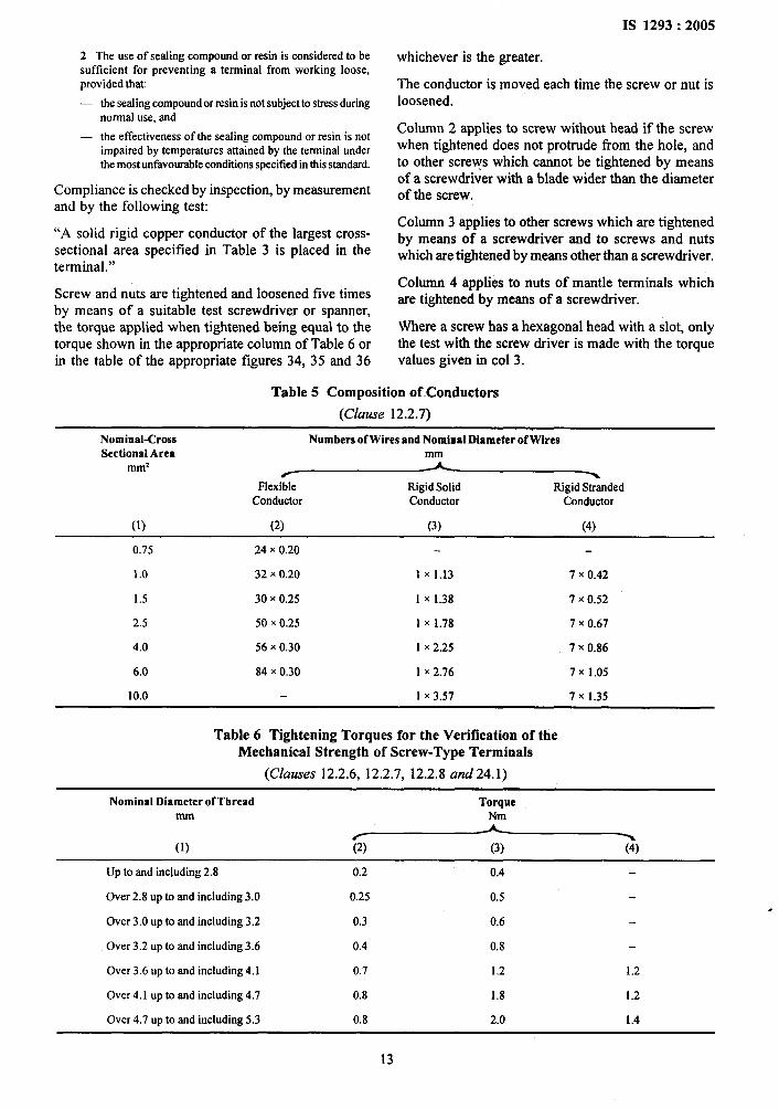
2 The use of sealing compound or resin is considered to besufficient for preventing a terminal from working loose,provided that
— the sealing compoundor resin isnot subjectto stressduringnormal use, and
— the effectiveness of the sealing compound or resin is notimpairedby temperaturesattainedby the terminalunderthemostunfavorable conditionsspecified in this standard.
Compliance is checked by inspection, by measurementand by the following test:
“A solid rigid copper conductor of the largest cross-sectional area specified in Table 3 is placed in theterminal.”
Screw and nuts are tightened and loosened five timesby means of a suitable test screwdriver or spanner,the torque applied when tightened being equal to thetorque shown in the appropriate column of Table 6 orin the table of the appropriate figures 34, 35 and 36
IS 1293:2005
whichever is the greater.
The conductor is moved each time the screw or nut isloosened.
Column 2 applies to screw without head if the screwwhen tightened does not protrude tiom the hole, andto other screws which cannot be tightened by meansof a screwdriver with a blade wider than the diameterof the screw.
Column 3 applies to other screws which are tightenedby means of a screwdriver and to screws and nutswhich are tightened by means other than a screwdriver.
Column 4 applies to nuts of mantle terminals whichare tightened by means of a screwdriver.
Where a screw has a hexagonal head with a slot, onlythe test with the screw driver is made with the torquevalues given in CO13.
Table 5 Composition of. Conductors
(Clause 12.2.7)
Nominal-Cross Numbers of Wires and Nominal D!ameter ofWtresSectional Area
mm2~
Flexible Rigid Solid Rigid StrandedConductor Conductor Conductor
(1) (2) (3) (4)
0.75 24X 0.20
1.0 32X 0.20 1X1.13 7 X0.42
1.5 30x 0.25 1 x 1.38 ~ x 0.52
2.5 50x 0.25 1 X 1.78 7 X (3.67
4.0 56x 0.30 1 x 2.25 ~ x (-).86
6.0 84X ().30 1 X z.~(j 7x 1.05
10.0 1 x 3.57 7X1,35
Table 6 Tightening Torques for the Verification of theMechanical Strength of Screw-Type Terminals
(Clauses 12.2.6, 12.2.7, 12.2.8 and 24.1)
Nominal Diameter of Thread Torquemm
~(1) (4)
Up to and including 2.8 0.2 0.4
Over 2.8 up to and including 3.0 0.25 0.5
Over 3.0 up to and including 3.2 0.3 0.6
Over 3.2 up to and including 3.6 0.4 0.8
Over 3.6 up to and including 4.1 0.7 1.2 1.2
Over 4.1 up to and including 4.7 0.8 1.8 1.2
Over 4.7 up to and including 5.3 0.8 2.0 1.4
‘,)
13
IS 1293:2005
During the test, terminals shall not work loose andthere shall be no damage, such as, breakage of screwor damage to the head slots (rendering the use of theappropriate screwdriver impossible), threads, washersor stirrups that will impair the further use of theterminals.
NOTES
1 For mantle terminals the specific nominal diameter is thatof the slotted stud.
2 The shape of the blade of the test screwdriver shall suit thehead of the screw to be tested.
3 The screw and nuts must not be tightened in jerks.
12.2.9 Clamping screws or nuts of earthing terminalswith screw clamping shall be adequately locked againstaccidental loosening and it shall not be possible toloosen them without the aid of a tool.
Compliance is checked by manual test.
NOTE — In general, the design of terminals shown in Fig, 34,35,36 and 37 provide sufficient resiliency to comply with thisrequirement; for other designs, special provisions, such as, theuse of an adequately resilient part which is not likely to beremoved inadvertently, may be necessary.
12.2.10 Earthing terminals with screw clamping shallbe such that there is no risk of corrosion resulting fromcontact between these parts and the copper of theearthing conductor, or any other metal that is in contactwith these parts.
The body of earthing terminals shall be of brass orother metal no less resistant to corrosion, unless it is apart of metal frame or enclosure, when the screw ornut shall be of brass or other metal no less resistant tocorrosion.
If the body of the earthing terminals is a part of a frameor enclosure of aluminium alloy, precautions shall betaken to avoid the risk of corrosion resulting fromcontact between copper and aluminium or its alloys.
Compliance is checked by inspection.
NOTE — Screw or nuts shall be of plated steel withstandhrgthe corrosion test is consideredto be of a metsdno less resistantto corrosion than brass,
12.2.11 For pillar terminals, the distance between theclamping screw and the end of the conductor whenfully inserted, shall be at least that specified inFig. 34.
NOTE—The minimum dktance between the clamping screwand the end of the conductor applies only to pillar terminals inwhich the conductor cannot pass right through.
For mantle terminals, the distance between the fixedpart and the end of the conductor when filly inserted,shall be at least that specified in Fig. 37.
Compliance is checked by measurement, after a solidconductor of the largest cross-sectional area specifiedin Table 3, has been fully inserted and filly clamped.
12.3 Screwless Terminals for External CopperConductors
12.3.1 Screwless terminals maybe of the type suitablefor rigid copper conductors only or of the type suitablefor both rigid and flexible copper conductors.
For the latter type the test have to be carried out withrigid conductors first and then repeated with flexibleconductors.
NOTE — This sub-clause ii not applicable to socket-outletprovided witi.
— screwless terminals requiring the fixing of special devicesto conductors before clamping them in the screwlessterminals, for example, flat push-on conductors,
— screwless terminals requiring twisting of the conductors,for example, those with twisted joints; and
— screwless terminals providing direct contact to theconductors by means of edges or points penetrating theinsulation.
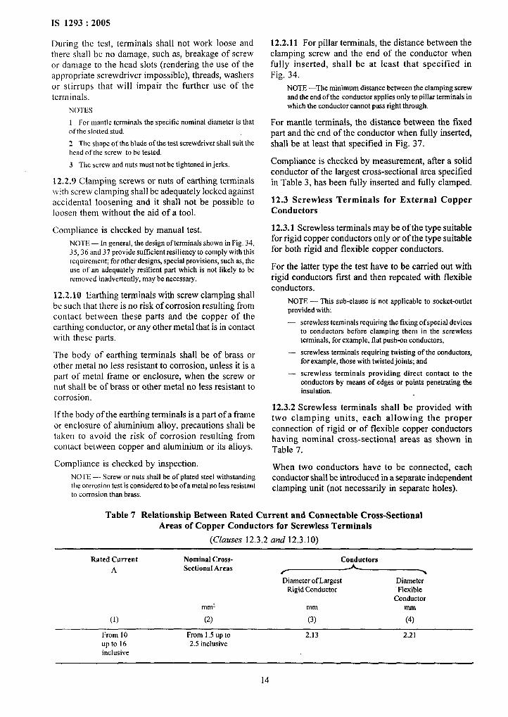
12.3.2 Screwless terminals shall be provided withtwo clamping units, each allowing the properconnection of rigid or of flexible copper conductorshaving nominal cross-sectional areas as shown inTable 7.
When two conductors have to be connected, eachconductor shall be introduced in a separate independentclamping unit (not necessarily in separate holes).
Table 7 Relationship Between Rated Current and Connectable Cross-SectionalAreas of Copper Conductors for Screwless Terminals
(Clauses 12.3.2 and 12.3.10)
Rated Current Nominal Cross- Conductors
A Sectional Areas FDiameter of Largest Diameter
Rigid Conductor FlexibleConductor
mm2 mm mm
(1) (2) (3) (4)
From 10 From 1.5 up to 2.13 2.21upto 16 2.5 inclusiveinclusive
14
IS 1293:2005
Compliance is checked by inspection and befitting clamping unit (not necessarily in separateconductors of the smallest and largest cross-sectional holes).
areas specified.It shall be possible to clamp securely any number of
12.3.3 Screwless terminals shall allow the conductor conductors-up tothemaxfium as designed.
to be connected without special preparation.Compliance is checked by inspection and by test with
Compliance is checked by inspection. the appropriate conductors (number and size).
NOTE— The term“specialpreparation”coverssolderingofthe wires of the conductor, use of terminal ends etc, but not 12.3.8 Screwless terminals of fixed socket-outlets shall
the reshapingof the conductorbeforeits introductionintothe be designed so that adequate insertion of the conductorterminalor the twistingof a flexibleconductorto consolidate is obvious and over insertion is prevented, if furtherthe end. insertion is liable to reduce the creepage distances and/
12.3.4 Parts of screwless terminals mainly intended or clearances required in Table 23, or to influence the
for carrying current shall be of materials as specified function of the socket-outlets.
in 26.5._ - NOTE— For the purpose of this requirements, an appropriatemarktngindicatingthe length of insulationto be removed before
Compliance is checked by inspection and by chemical the insertion of the conductor into the screwless terminals may
analysis. be put on the socket-outletor given in an instructionsheet which
NOTE— Springs,resilientunits,clampingplatesand the likeaccompanies the socket-outlet.
are not considered as part mainly intended for carrying current. Compliance is checked by inspection and by the test
12.3.5 Screwless terminals shall be so designed that of 12.3.10.’
they clamp the specified conductors with sufficientcontact pressure and without undue damage to the
12.3.9 Screwless terminals shall be properly fixed to
conductor.the socket-outlet.
The conductor shall be clamped between metal They shall not work loose when the conductors are
surfaces. connected or disconnected during installation.
NOTE— Conductorsareconsideredto beundulydarnagedif Compliance is checked by inspection and by the teststhey showappreciabledeep or sharp indentations. of 12.3.10.
Compliance is checked by inspection and by the testof 12.3.10.
Covering with sealing compound without other meansof locking is not sufficient. Self-hardening resins may,
12.3.6 It shall be clear how the insertion and however, be used to fix terminals which are not subject
disconnection of the conductors is intended to be to mechanical stress in normal use.
effected.12.3.10 Screwless terminals shall withstand the
The intended disconnection of a conductor shall mechanical stresses occurring in normal use.require an operation, other than a pull on the conductor,so that it can be made manually with or without the Compliance is checked by the following test, which is
help of a general purpose tool. carried out with uninsulated conductors on onescrewless terminals of each sample using a new
It shall not be possible to conti.ue the openings for the samples for each test.use of a tool to assist the connection or disconnectionwith the opening intended for the conductor. The test is carried out with solid copper conductor,
frost with conductors having the largest cross-sectionalCompliance is checked by inspection and by the test area, and then with conductors having the smallestof 12.3.10. cross-sectional area specified in Table 7.
12.3.7 Screwless terminals which are intended to be Conductors are connected and disconnectedused for the interconnection of two or more conductors Table 7 five times, new conductors being used eachshall be so designed that: time, except for the fifth time, when the conductors
a) during the insertion, the operation of the used for the fourth insertion are clamped at the same
clamping means of the one of the conductors is place. For each insertion, the conductors are either
independent of the operation of that for the other pushed as far as possible into the terminal or are
conductor(s). inserted so that adequate connection is obvious.
{
b) during the disconnection, the conductor can bedisconnected either at the same time or
After each insertion, the conductor is subjected to pullof the value shown in Table 8. The pull is applied
separately; and without jerks, for 1 minute in the direction of the
c) each conductor shall be introduced in a separate longitudinal axis of the conductor space.
15

IS 1293:2005
Table 8 Value for Pull Test for Screwless-Type Terminals
(Clause 12.3. 10)
Rated Pull
Current N
A
(1) (2)
10uptoand 30including16
During the application of the pull, the conductor shallnot come out of the screwless terminal.
The test is then repeated with rigid stranded copperconductors having the largest and smallest cross-sectional areas specified in Table 7. These conductorsare, however, inserted and disconnected only once.
Screwless terminals intended for both rigid and flexibleconductors shall also be tested with flexibleconductors, applying five connections anddisconnections.
For fixed socket-outlets with screwless terminals eachconductor is subjected for 15 min to a circular motion(1 O ~ 2) rev/rein using an apparatus, an example ofwhich is shown in Fig, 32. The conductor is subjectedto a pull having a value shown in Table 9.
During the test the conductor shall not move noticeablyin the clamping unit.
After these tests, neither the terminals nor the clampingmeans shall have worked loose and the conductors shallshow no deterioration impairing their further use.
12.3,11 Screwless terminals shall withstand theelectrical and thermal stresses occurring in normal use.
Compliance is checked by the following test (a) and(b), which are carried out on five screwless terminalsof socket-outlets which have not been used for anyother test.
Both tests have to be carried out with new copperconductors.
a) The test is carried out loading the screwlessterminals for one hour with an alternatingcurrent, as specified in Table 10, and connectingrigid solid conductors 1 m long having the cross-sectional area as specified in Table 10.
The test is carried on each clamping unit.
During the test the current is not passed throughthe socket-outle4 but only through the terminals.
Immediately after this period the voltage dropacross each screwless terminal is measured withrated current flowing.
In no case shall the voltage drop exceed 15 mV.
The measurement shall be made across eachscrewless terminals and as near as possible tothe pla~e of contact.
If the back connection of the terminals is notaccessible, the sample may be adequatelyprepared by the manufacturer, care shall betaken not to affect the behaviour of theterminals.
Care shall be taken that, during the period ofthe test, including the measurements, theconductors and the measurement means are notmoved noticeably.
Table 9 Values for Flexing under Mechanical LevelTest for Copper Conductors
(Clauses 12.3.10 and 12.3.1 1)
Nominal Conductor Diameter of Height Mass forCross-Sectional Bushing HolelJ (H)2) Conductor
Areamm2 mm mm kg
(1) (2) (3) (4)
0.5 6.5 260 0.3
0.75 6.5 260 0.4
1.0 6.5 260 0.4
1.5 6.5 260 0.4
2.5 9.5 280 0.7
4.0 9.5 280 0.9
6.0 9,5 280 1.4
10.0 9.5 280 2.0
0 If the bushing ho]e di~eter is not Iwge enough to ~co~odate the conductor without blndlng, a bushing having the next hirgel hole
size may be used.
z) ‘folermce forheightH = ● 15mm.
16
P,..!.
,.
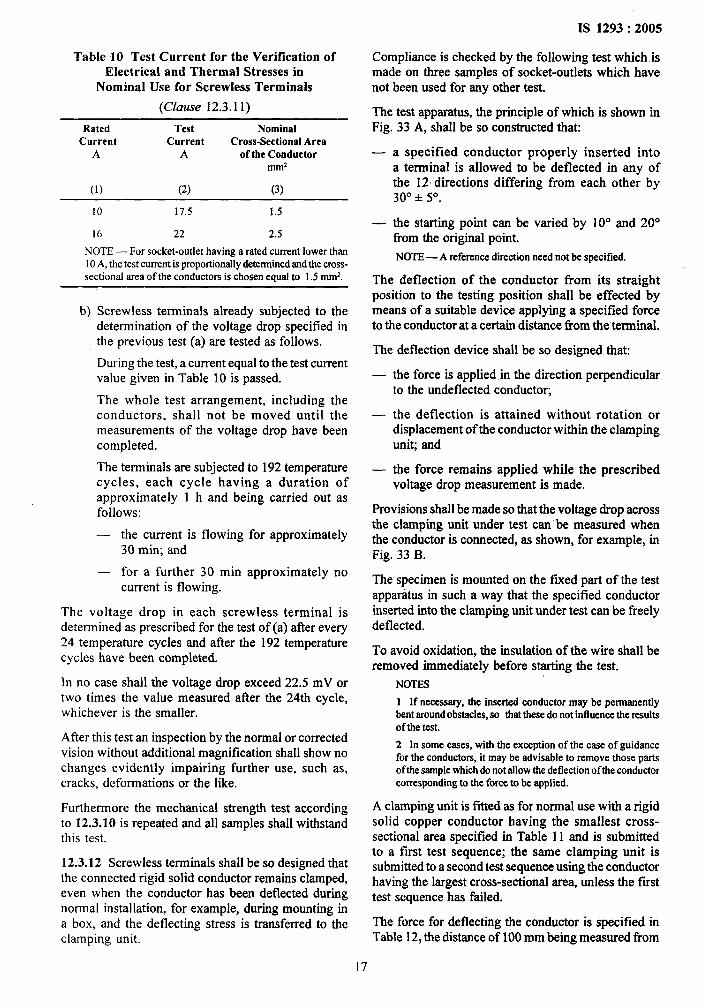
Table 10 Test Current for the Verification ofElectrical and Thermal Stresses in
Nominal Use for Screwless Terminals
(Clause 12.3.1 1)
Rated Test NominalCurrent Current Cross-SectionalArea
A A of the Conductor~ml
(1) (2) (3)
10 17.5 1.5
16 22 2.5
NOTE— For socket-outlet having a rated current lower than10A, the test current is proportionallydeterminedandthe cross-sectional area of the conductors is chosen equal to 1.5 mmz.
b) Screwless terminals already subjected to thedetermination of the voltage drop specified inthe previous test (a) are tested as follows.
During the test, a current equal to the test currentvalue given in Table 10 is passed.
The whole test arrangement, including theconductors, shall not be moved until themeasurements of the voltage drop have beencompleted.
The terminals are subjected to 192 temperaturecycles, each cycle having a duration ofapproximately 1 h and being carried out asfollows:
— the current is flowing for approximately30 rein; and
— for a further 30 min approximately nocurrent is flowing.
The voltage drop in each screwless terminal isdetermined as prescribed for the test of (a) after every24 temperature cycles and after the 192 temperaturecycles have been completed.
In no case shall the voltage drop exceed 22.5 mV ortwo times the value measured after the 24th cycle,whichever is the smaller.
After this test an inspection by the normal or correctedvision without additional magnification shall show nochanges evidently impairing further use, such as,cracks, deformations or the like.
Furthermore the mechanical strength test accordingto 12.3.10 is repeated and all samples shall withstandthis test.
12.3.12 Screwless terminals shall be so designed thatthe connected rigid solid conductor remains clamped,even when the conductor has been deflected duringnormal installation, for example, during mounting ina box, and the deflecting stress is transferred to theclamping unit.
IS 1293:2005
Compliance is checked by the following test which ismade on three samples of socket-outlets which havenot been used for any other test.
The test apparatus, the principle of which is shown inFig. 33 A, shall be so constructed that:
—
—
a specified conductor properly inserted intoa terminal is allowed to be deflected in any ofthe 12 directions differing from each other by30° * 5°.
the starting point can be varied by 10° and 20°from the o;ginal point.
NOTE— A referenee direction need not be specified.
The deflection of the conductor from its straightposition to the testing position shall be effected bymeans of a suitable device applying a specified forceto the conductor at a certain distance from the terminal.
The deflection device shall be so designed that:
—
—
—
the force is applied in the direction perpendicularto the unreflected conductor;
the deflection is attained without rotation ordisplacement of the conductor within the clampinguni~ and
the force remains applied while the prescribedvoltage drop measurement is made.
Provisions shall be made so that the voltage drop acrossthe clamping unit under test can be measured whenthe conductor is connected, as shown, for example, inFig. 33 B.
The specimen is mounted on the f~ed part of the testapparatus in such a way that the specified conductorinserted into the clamping unit under test can be freelydeflected.
To avoid oxidation, the insulation of the wire shall beremoved immediately before starting the test.
NOTES
1 If necessary,the hssertql conductormay be permrmenttybent aroundobstacles, so that these do not influence the resultsof the test.
2 ln some cases, with the exeeption of the case of guidancefor the conductors, it maybe advisable to remove those partsof the samplewhich do not allow the deflection of the conductorcorrespondhg to the force to be applied.
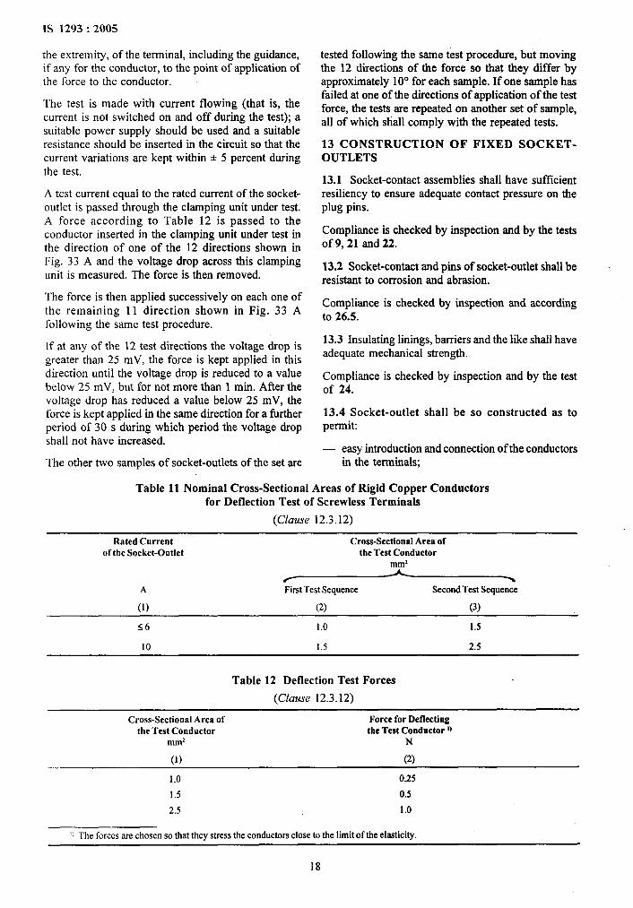
A clamping unit is fitted as for normal use with a rigidsolid copper conductor having the smallest cross-sectional area specified in Table 11 and is submittedto a first test sequence; the same clamping unit issubmitted to a second test sequence using the conductorhaving the largest cross-sectional are% unless the fusttest sequence has failed.
The force for deflecting the conductor is specified inTable 12, the distance of 100 mm being measured from
17
,.. .
‘1
i
IS 1293:2005
the extremity, of the terminal, including the guidance,if any for the conductor, to the point of application ofthe force to the conductor.
The test is made with current flowing (that is, thecurrent is not switched on and off during the test); asuitable power supply should be used and a suitableresistance should be inserted in the circuit so that thecurrent variations are kept within + 5 percent duringthe test.
A test current equal to the rated current of the socket-outlet is passed through the clamping unit under test.A force according to Table 12 is passed to theconductor inserted in the clamping unit under test inthe direction of one of the 12 directions shown inFig. 33 A and the voltage drop across this clampingunit is measured. The force is then removed.
The force is then applied successively on each one ofthe remaining 11 direction shown in Fig. 33 Afollowing the same test procedure.
If at any of the 12 test directions the voltage drop isgreater than 25 mV, the force is kept applied in thisdirection until the voltage drop is reduced to a valuebelow 25 mV, but for not more than 1 min. After thevoltage drop has reduced a value below 25 mV, theforce is kept applied in the same direction for a firtherperiod of 30 s during which period the voltage dropshall not have increased.
The other two samples of socket-outlets of the set are
tested following the same test procedure, but movingthe 12 directions of the force so that they differ byapproximately 10° for each sample. If one sample hasfailed at one of the directions of application of the testforce, the tests are repeated on another set of sample,all of which shall comply with the repeated tests.
13 CONSTRUCTION OF FIXED SOCKET-OUTLETS
13.1 Socket-contact assemblies shall have sufficientresiliency to ensure adequate contact pressure on theplug pins.
Compliance is checked by inspection and by the testsof 9, 21 and 22.
13.2 Socket-contact and pins of socket-outlet shall beresistant to corrosion and abrasion.
Compliance is checked by inspection and accordingto 26.5.
13.3 Insulating linings, barriers and the like shall haveadequate mechanical strength.
Compliance is checked by inspection and by the testof 24.
13.4 Socket-outlet shall be so constructed as topermib
— easy introduction and connection of the conductorsin the terminals;
Table 11 Nominal Cross-Sectional Areas of Rigid Copper Conductorsfor Deflection Test of Screwless Terminals
(Clause 12.3, 12)
Rated Current Cross-Sectional Area ofof the Socket-Outlet the Test Conductor
mm2
A First Test Sequence Second Test Sequence
(1) (2) (3)
56 1.0 1.5
10 1.5 2.5
Table 12 Deflection Test Forces
(Clause 12.3.12)
Cross-SectionalArea of Force for Deflectingthe Test Conductor the Test Conductor 1,
mm2 N
(1) (2)
1.0 0.25
1.5 0.5
2.5 1.0
II The forces me chosen so that they stress the conductors close to the timit Ofthe ela.$ticity.
18
easy fixing of the base to a wall or in a mountingbox;
correct positioning of the conductors;
adequate space between the underside of the baseand the surface on which the base is mounted orbetween the side of the base and the enclosure(cover or box) flush mounted so that, afterinstallation of the socket-outlet, the insulation ofthe conductors is not necessarily pressed againstlive parts of different polarity.
I For
NOTE — This requirement does not imply that the metal partsof the terminals are necessarily protected by insulating barriersor insulating shoulders, from contact, due to incorrectinstallation of the terminal metal partwith the insulation of theconductor.
surface type socket-outlet to be mounted on amounting plate a wiring channel may be needed tocomply with this requirement.
In addition, socket-outlets classified as design A shallpermit easy positioning and removal of the cover orcover-plate, without displacing the conductors.
Compliance is checked by inspection and by aninstallation test with conductors of the largest cross-sectional area specified, for the relevant terminal size,in Table 3.
13.5 Socket-outlet shall be so designed that fullengagement of associated plugs is not prevented byany projection from their engagement face.
Compliance is checked by determining that the gapbetween the engagement face of the socket-outlet andthe plug does not exceed 1 mm when the plug isinserted into the socket-outlet as far as it will go.
13.6 If covers are provided with bushings for the entryholes for the pins, it shall not be possible to removethem from the outside or for them to become detachedinadvertently from the inside, when the cover isremoved.
13.7 Covers, or cover-plates or parts of them, whichare intended to ensure protection against electric shock,shall be held in place at two or more points by effectivefixings.
Covers, cover-plates or parts of them maybe fixed bymeans of a single fixing, for example, by a screw,provided that they are located by another means (forexample, by a shoulder).
NOTES
1 It is recommended that the fixings of covers or cover-platesbe captive.
The use of tight fixing washers of cardboard or the like isdeemed to be an adequatemethod for securingscrews intendedto be captive,
2 Non-earthed metal parts separated from live parts in such away that creepage distance and clearances have the values
IS 1293:2005
specified in Table 3, are not considered as accessible if therequirements oftbis sub-clause are met.
Where the fixing of covers or cover-plates of socket-outlets of design A serve to fix the base, there shall bemeans to maintain the base in position, even afterremoval of the covers or cover-plates.
Compliance with the requirements of safety andconstruction is checked according to 13.7.1, 13.7.2or 13.7.3.
13.7.1 For covers or cover-plates whose fixing are ofthe screw-type:
By inspection only.
13.7.2 For covers or cover-plates where fixing is notdependent on screws and where removal is obtainedby applying a force in a direction approximatelyperpendicular to the mounting/supporting surface(see Table 13):
— where their removal may give access, with thestandard test finger, to live parts by the test of24.14;
— when their removal may give access, with thkstandard test finger, to non-earthed metal partsseparated from live parts in such a way thatcreepage distance and clearances have the valuesspecified in Table 23 by the,tests of 24.15;
— when their removal may give access, with thestandard test finger, only to:
.
●
✎
✎
insulating parts, or
earthed metal parts, or
metal parts separated flom live parts in such away that creepage distances and clearances havetwice the values specified in Table 23, or
live parts of safety extra-low voltrwe CSELV)circuits not greate~ than 25 V ac by ‘tie tests o~24.16.
13.7.3 For covers or cover-plates whose fixing is notdependent on screws and Where removal is obtainedby using a tool, in accordance with the manufacturer’sinstructions given in an instruction sheet or in acatalogue: by the same tests of 13.7.2 except that thecovers or cover-plates or parts of them need not comeout when applying a force not exceeding 120 N indirections perpendicular to the mounting/supportingsurface.
13.8 A cover-plate intended for a socket-outlet withearthing contact shall not be interchangeable with acover-plate intended for a socket-outlet withoutearthing contact, if such interchange changes theclassification of the socket-outlet according to 7.1.2.
NOTE — This requirement applies to accessories of the samemanufacturer.
19
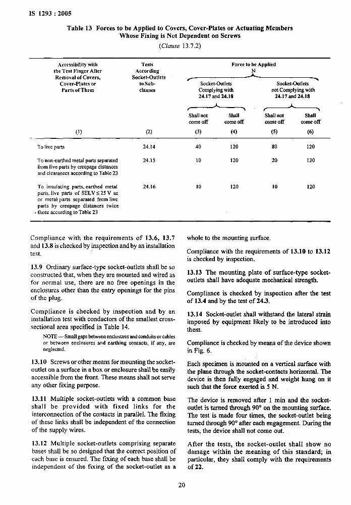
IS 1293:2005
Table 13 Forces to be Applied to Covers, Cover-Plates or Actuating MembersWhose Fixing is Not Dependent on Screws
(Clause 13.7.2)
Accessibility with Tests Force to be Appliedthe Test Finger After AccordingRemoval of Covers, Socket-Outlets ~
Cover-Plates or to Sub- Socket-Outlets Socket-outletsParts of Them clauses Complying with not Complying with
24.17 and 24.18 24.17 and 24.18
Shall not Shall Shall not Shallcome off come off come off come off
(1) (2) (3) (4) (5) (6)
To live parts 24.14 40 120 80 120
To non-earthed metal parts separated 24.15 10 120 20 120from live parts by creepage distancesand clearances according to Table 23
To insulating parts, earthed metal 24.16 10 120 10 120parts, live parts of SELVs 25 V acor metal parts separated from liveparts by creepage distances twice
. those according to Table 23
Compliance with the requirements of 13.6, 13.7and 13.8 is checked by inspection and by an installationtest.
13.9 Ordinary surface-type socket-outlets shall be soconstructed that, when they are mounted and wired asfor normal use, there are no free openings in theenclosures other than the entry openings for the pinsof the plug.
Compliance is checked by inspection and by aninstallation test with conductors of the smallest cross-sectional area specified in Table 14.
NOTE— Smallgaps betweenenclosuresand conduitsor cablesor between enclosures and earthing contacts, if any, areneglected.
13.10 Screws or other means for mounting the socket-outlet on a surface in a box or enclosure shall be easilyaccessible from the front. These means shall not serveany other fixing purpose.
13.11 Multiple socket-outlets with a common baseshall be provided with fixed links for theinterconnection of the contacts in parallel. The fixingof these links shall be independent of the connectionof the supply wires.
13.12 Multiple socket-outlets comprising separatebases shall be so designed that the correct position ofeach base is ensured. The fixing of each base shall beindependent of the fixing of the socket-outlet as a
whole to the mounting surface.
Compliance with the requirements of 13.10 to 13.12is checked by inspection.
13.13 The mounting plate of surface-type socket-outlets shall have adequate mechanical strength.
Compliance is checked by inspection after the testof 13.4 and by the test of 24.3.
13.14 Socket-outlet shall withstand the lateral strainimposed by equipment likely to be introduced intothem.
Compliance is checked by means of the device shownin Fig. 6.
Each specimen is mounted on a vertical surface withthe plane through the socket-contacts horizontal. Thedevice is then fully engaged and weight hung on itsuch that the force exerted is 5 N.
The device is removed after 1 min and the socket-outlet is turned through 90° on the mounting surface.The test is made four times, the socket-outlet beingturned through 90° after each engagement. During thetests, the device shall not come out.
After the tests, the socket-outlet shall show nodamage within the meaning of this standard; inparticular, they shall comply with the requirementsof 22.
20
IS 1293:2005
13.15 Socket-outlet shall not be an integral part oflamp holders.
Compliance is checked by inspection.
13.16 Socket-outlet other than ordinary shall betotally enclosed when fitted with screws conduits orwith polyvinyl chloride sheathed or similar type ofcables and without a plug in position.
Surface-type socket-outlet other than ordinary shallhave provisions for opening a drain hole at least5 mm in diameter, or 20 mmz in area with a width anda length of at least 3 mm.
If the position of the lid is such, that only one mountingpositioh is possible, the drain hole shall be effective
1
in that position. Alternatively the drain hole shall beeffective in at least two positions of the socket-outletwhen this is mounted on a vertical wall, one of thesewith the conductors entering at the top and the other
i
with the conductors entering at the bottom.
Lid springs, if any, shall be of corrosion resistantmaterial, such as, bronze or stainless steel.
Compliance is checked by inspection, by measurementand by the test of 16.2.
NOTES
1 Total enclosurewhen the plug is not in position may beachieved by means of a lid.
2 This requirement does not imply that the lid, if any, or theentry openings for the pins need be closed when the plug is notin position, provided that socket-outlets pass the relevant testfor the verification of the ingress of water.
3 A drain hole in the back of the enclosure is deemed to beeffective only if the design of the enclosure ensure a clearanceor at least 5 mm from the wall, or provided a drainage channelof at least the size specified.
13.17 Earthing pins shall have adequate mechanicalstrength.
Compliance is checked by inspection and for pinswhich are not solid, by the test of 14.2 which is madeafter the test of 21.
13.18 Earthing contacts and neutral contacts shall belocked against rotation and removable only with theaid of a tool, after dismantling the socket-outlet fromthe installation.
Compliance is checked by inspection and by manualtest.
NOTE — A design permitting the removal of a contact withoutthe aid of a tool, after removal of an enclosure requiring theuse of a tooI, is not allowed.
13.19 Metal strips of the earthing circuit shall haveno burrs which might damage the insulation of thesupply conductors.
Compliance is checked by inspection.
13.20 Socket-outlet to be installed in a box shall be
so designed that the conductor ends can be preparedafter the box is mounted in position, but before thesocket-outlet is fitted in the box.
Compliance is checked by inspection.
13.21 Inlet opening shall allow the introduction ofthe conduit or the protection covering of the cable soas afford complete mechanical protection.
In surface-type socket-outlet the inlet opening forconduit entries, or at least two of them if there aremore than one, shall be capable of accepting conduitsize of 16, 20, 25 or 32 or a combination of at leasttwo of arty of these sizes.
In surface type socket outlets, the inlet opening forcable entries shall preferably be capable of acceptingcables having the dimensions specified in Table 14 orbe as specified by the manufacturer.
Compliance is checked by inspection and bymeasurement.
NOTE— Inletopeningsof adequatesizemayalsobeobtainedby the use of knock-outs or of suitable insertion pieces.
13.22 Membranes (grommets) in inlet openings shallbe reliably fixed and shall not be displaced by themechanical and thermal stresses occurring in normaluse.
Compliance is checked by the following testi
Membranes are tested when assembled in theaccessory.
First the accessories are fitted with membranes whichhave been subjected to the treatment specified in 16.1.
The accessories are then placed for 2 h in a heatingcabinet as described in 16.1, the temperature beingmaintained at 40 ● 2°C.
Immediately after this period, a force of 30 N is appliedfor 5s to various parts of the membranes by means ofthe tip of a straight unjoipted test finger of the samedimensions as the standard test finger shown in Fig. 2.
During these tests, the membranes shall not deform tosuch an extent that live parts become accessible.
For membranes likely to be subjected to an axial pullin normal use, art axial pull of 30 N is applied for 5 s.
During this test, the membranes shall not come out.
The test is then repeated with membranes which havenot been subjected to any treatment.
13.23 It is recommended that membranes in inletopenings be so designed and made of such materialthat the introduction of the cables into the accessoryis permitted when the ambient temperature is low.
NOTE-The compliancewith thk recommendationis requireddue to instdation practices in cold conditions.
s
‘1
.
21
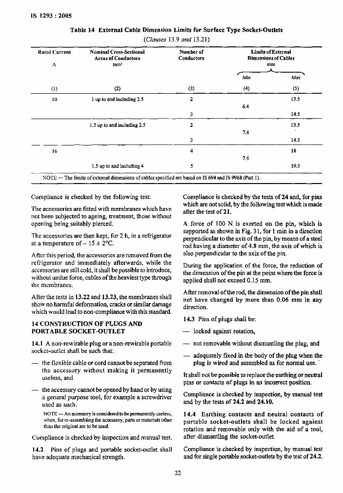
IS 1293:2005
Table 14 External Cable Dimension Limits for Surface Type Socket-Outlets
(Clauses 13.9 and 13.21)
Rated Current Nominal Cross-Sectional Number of Limits of ExternalAreas of Conductors Conductors Dimensions of Cables
A ~m2
~
(1) (2) (3) (4) (5)
10 1 up to and including 2.5 2 13.5
6.4
3 14.5
1.5 up to and including 2.5 2 13.5
7.4
3 14.5
16 4 18
7’.6
1.5 up to and inchsdlng 4 5 19.5
NOTE— The limitsof externaldimensionsof cablesspecifiedarebased on IS 694 and IS 9968 (Part 1).
Compliance is checked by the following test
The accessories are fitted with membranes which havenot been subjected to ageing, treatment, those withoutopening being suitably pierced.
The accessories are then kept, for 2 h, in a refrigeratorat a temperature of – 15 + 2“C.
After this period, the accessories are removed fi-om therefrigerator and immediately afterwards, while theaccessories are still cold, it shall be possible to introduce,without undue force, cables of the heaviest type throughthe membranes.
After the tests in 13.22 and 13.23, the membranes shallshow no harmfhl deformation, cracks or similar damagewhich would lead to non-compliance with this standard.
14 CONSTRUCTION OF PLUGS ANDPORTABLE SOCKET-OUTLET
14.1 A non-rewirable plug or a non-rewirable portablesocket-outlet shall be such that
the flexible cable or cord cannot be separated fromthe accessory without making it permanentlyuseless, and
— the accessory cannot be opened by hand or by usinga general purpose tool, for example a screwdriverused as such.
NOTE — An accessoryis eonsidem.dto be permanentlyuseless,when, for re-assembling the accessory, parts or materials otherthan the original are to be used.
Compliance is checked by inspection and manual test.
14.2 Pins of plugs and portable socket-outlet shallhave adequate mechanical strength.
22
Compliance is checked by the tests of 24 and, for pinswhich are not soli~ by the following test which is madeafter the test of 21.
A force of 100 N is exerted on the pin, which issupported as shown in Fig. 31, for 1 min in a directionperpendicular to the axis of the pin, by means of a steelrod having a diameter of 4.8 mm, the axis of which isalso perpendicular to the axis of the pin.
During the application of the force, “the reduction ofthe dimension of the pin at the point where the force isapplied shall not exceed 0.15 mm.
Afier removal of the rod, the dimension of the pin shallnot have changed by more than 0.06 mm in anydirection.
14.3 Pins of plugs shall be:
— locked against rotation,
— not removable without dismantling the plug, and
— adequately fixed in the body of the plug when theplug is wired and assembled as for normal use. ‘
It shall not be possible to replace the earthing or neutralpins or contacts of plugs in an incorrect position.
Compliance is checked by inspection, by manual testand by the tests of 24.2 and 24.10.
14.4 Earthing contacts and neutral contacts ofportable socket-outlets shall be locked againstrotation and removable only with the aid of a tool,atler dismantling the socket-outlet.
Compliance is checked by inspection, by manual testand for single portable socket-outlets by the test of 24.2.
14.5 Socket-contact assemblies shall have sufficientresiliency to ensure adequate contact pressure.
This requirement may also cover socket-outlets wherethe contact pressure relies on insulating parts havingsuch characteristics as to ensure a safe and permanentcontact in any condition of normal use, with regard inparticular to shrinkage, ageing and yielding.
Compliance is checked by inspection and by the testsof 9, 21 and 22.
14.6 Pin and socket-contacts shall be resistant tocorrosion and abrasion.
Compliance is checked by an appropriate test, whichis under consideration.
14.7 The enclosure of rewirable accessories shallcompletely enclose the terminals and the ends offlexible cable and cord.
The construction shall be such that the conductors canbe properly connected and that, when the accessory iswired and assembled as for normal use, there is no riskthat:
—
—
pressing the cores together cause darnage to theconductors insulation likely to result in abreakdown of the insulation;
a core, the conductor of which is connected to alive terminal, is necessarily pressed againstaccessible metal parts; and
a core, the conductor of which is connected to theearthing terminal, is necessarily pressed against liveparts.
14.8 Rewirable accessories shall be so designed thatterminal screws or nuts cannot become loose and fallout of position in such a way that they establish anelectrical connection between live parts and the earthingterminal or metal parts connected to the earthingterminal.
Cotipliance with the requirements of 14.7 and 14.8 ischecked by inspection and by manual test.
14.9 Rewirable accessories with earthing contact shallbe designed with ample space for slack of the earthingconductor in such a way that, if the strain relief isrendered inoperative, the connection of the earthingconductor is subjected to strain after the connectionsof the current-carrying conductors and that, in case ofexcessive stresses, the earthing conductor will breakafter the current-carrying conductors.
Compliance is checked by the following test
The flexible cable or cord is connected to the accessoryin such a way that the current-carrying conductors areled from the strain relief to the corresponding terminalsalong the shortest possible path.
IS 1293:2005
After they are correctly connected, the core of theearthing conductor is led to its terminal and cut off at adistance 8 mm longer than necessary for its correctconnection.
The earthing conductor is then connected to theterminal. It must be then possible to house the loop,which is formed by the earthing conductor owing to itssurplus length when the accessory is assembledcorrectly.
In non-rewirable non-moulded on accessories withearthing contact the length of the conductors betweenthe terminations and the cord anchorage shall be soadjusted that the current-carrying conductors will bestressed before the earthing conductors, if the flexiblecable slips in its anchorage.
Compliance is checked by inspection.
14.10 Terminals of rewirable accessories shall be solocated or shielded that they comply with the followingtest:
A 6 mm length of insulation is remc@ed from the endof a flexible conductor, having the minimum nominalcross-sectional area specified in Table 3. One wire ofthe flexible conductor is left free and remaining wiresare fully inserted into and clamped in the terminal, asfor normal use.
The fi-ee wire is bent, without tearing the insulationback, in every possible direction, but without makingsharp bends around barriers.
The free wire of a conductor connected to a liveterminal shall not touch any accessible metal part orbe able to emerge from the enclosure when theaccessory has been assembled.
The free wire of a conductor connected to an earthingterminal shall not touch a live part.
If necessay, the test is repeated with the free wire inanother position.
The prohibition against making sharp bends aroundbarriers does not imply that the free wire shall be keptstraight during the test. Sharp bends are made if it isconsidered likely that such bends can occur during thenormal assembly of the plug or portable socket-outlet,for example when a cover is pushed on.
14.11 For rewirable plugs and rewirable portablesocket-outlets:
— it shall be clear how the relief from strain and theprevention of twisting is intended to be effected;
— the cord anchorage, or at least part of it, shall beintegral with or permanently f~ed to one of thecomponent parts of the plug or portable socket-outlet;
(,’
,.
s.,>..@
@
.
i
23
Is
.
—
—
—
1293:2005
make-shift methods, such as, tying the cable orcord in a knot ortying the ends with string, shallnot be used;
cord anchorages shall besuitable for tie differenttypes of flexible cable which maybe connectedincluding cables having rubber sheath ofmaximumdiameter as shown in Tables 17 and 18, and theireffectiveness shall not depend upon the assemblyof the parts of the body;
cord anchorages shall be of insulating material orbe provided with an insulating lining fixed to themetal parts;
metal parts of the cord anchorage, includingclamping screws, shall be insulated from theearthing circuit.
Compliance is checked by inspection and, isapplicable, by manual test.
14.12 Insulating parts which kept the live parts inposition shall be reliably fixed together, and it shall notbe possible to dismantle the accessory without the aidof a tool.
Compliance is checked by inspection and by manualtest.
14.13 If covers of portable socket-outlets are providedwith bushings for the entry holes for the pins, thesebushes shall not be allowed to be removed from theoutside or to become detached inadvertently from theinside, when the cover is removed.
14.14 Screws intended to allow the access to theinterior of the accessory shall be captive.
NOTE— The use of tight fitting washers of cardboard or thelike is deemed to be an adequate method for securing screwswhich must be captive.
Compliance with the requirements of 14.13 and 14.14is checked by inspection.
14.15 The engagement face of plugs shall have noprojections other than the pins, when the plug is wiredand assembled as for normal use.
Compliance is checked by inspection, after fittingconductors of the largest cross-sectional area specifiedin Table 3.
NOTE— The earthing contacts including collars and recessesare not considered as projections from the engagements face.
14.16 Portable socket-outlet shall be so designed thatfull engagement of associated plugs is not preventedby any projection from their engagement face.
Compliance is checked by the test of 13.5.
14.17 Accessories other than ordinary shall beprovided with a gland or the like for sealing the cableentries.
Plugs other than ordinary shall be adequatelyenclosed when fitted with a flexible cable as for normaluse.
Portable socket-outlets other than ordinary shallremain totally enclosed even without a plug inengagement.
Lid springs, if any, shall be of corrosion resistantmaterial, such as, bronze or stainless steel.
Compliance is checked by inspection and by the testof 16.2.
NOTE— Adequate enclosure when the plug is not in positionmay be achieved by means of a lid.
This requirement does not imply that the lid, if any, onthe entry openings for the pins need be closed whenthe plug is not in position, provided that the accessorypasses the relevant tests for the verification of the ingressof water.
14.18 Portable socket-outlets having means forsuspension from a wall or other mounting surfaces shallbe so designed that the suspension means do not allowaccess to live parts and that any failure during the testdoes not expose live parts.
There shall be no flee openings between the spaceintended for the suspension means fixed to the walland the live parts.
Compliance is checked by inspection and by the testsof24.11, 24.12 and 24.13.
14.19 Combinations of plugs and socket-outlets withcircuit-breakers or other protective devices shallcomply with the relevant standards, if any.
Compliance is checked by reference to appropriatestandards if any.
14.20 Portable accessories shall not bean integral partof lampholders.
Compliance is checked by inspection.
14.21 Plugs classified exclusively as plugs forequipment of class II shalI be rewirable or non-rewirable type.
If they are incorporated in a cord set, this shall beprovided with a connector for equipment of class 11,
If they are incorporated in a cord extension set, thisshall be provided with a portable socket-outlet forequipment of class H.
NOTE — Cord extension sets for equipments of class II arenot atlowed.
Compliance is checked by inspection.
14.22 Components, such as, switches and fuses,incorporated in accessories shall comply with the
,.i
24
IS 1293:2005
relevant Indian Standard, if any, as far as it reasonablyapplies.
Compliance is checked by inspection and, if necessary,by testing the component according to the relevantIndian Standard, if any.
14.23 If a plug is an integral part of plug-in equipment,that equipment shall not cause overheating of the pinsor impose undue strain on fixed socket-outlets.
NOTE — Examples of equipments with plugs which are anintegral part are razors and lamps with rechargeable batteries,plug-in transformers, etc.
For two-pole plugs, with or without earthing contact,compliance is checked by the tests of 14.23.1and 14.23.2.
14.23.1 The plug of the equipment is inserted into afixed socket-outlet complying with this standard, thesocket-outlet being connected to a supply voltage equalto 1.1 times the highest rated voltage of the equipment.
After 1 h, the temperature-rise of the pins? shall notexceed 45”C.
14.23.2 The equipment is then inserted into a fixedsocket-outlet complying with this standard, the socket-outlet being pivoted about a horizontal axis throughthe axis of the live socket-contacts at a dktance of8 mm behind the engagement face of the socket-outletand parallel to this engagement face.
The additional torque which has to be applied to thesocket-outlet to maintain the engagement face in thevertical plane shall not exceed 0.25 Nm.
14.24 Plugs shall be shaped in such a way and madeof such a material that they can easily be withdrawnby hand from the relevant socket-outlet.
In addition the gripping surfaces shall be so designedthat the plug can be withdrawn without having to pullon the flexible cable or cord.
16 RESISTANCE TO AGEING, TO HARMFULINGRESS OF WATER AND TO HUMIDITY
16.1 Resistance to Ageing
Accessories shall be resistant to ageing.
Parts intended for decorative purpose only, such as,certain lids, are to be removed before the test.
Compliance is checked by the following test:
Accessories, mounted as for normal use, are subjectedto a test in a heating cabinet with an atmosphere havingthe composition and pressure of the ambient air andventilated by natural circulation.
Accessories other than ordinary are tested after havingbeen mounted and assembled as prescribed in 16.2.
The temperature in the cabinet is 70 ● 2“C.
The samples are kept in the cabinet for 7 days (168 h).
The use of an electrically heated cabinet isrecommended.
Natural circulation may be provided by holes in the~’:k;?.
walls of the cabinet. j
After the treatment, the samples are removed from the .,cabinet and kept at room” temperature and relativehumidity bemeen 45 percent rind 55 percent for at
s‘1.,, ..
least 4 days (96 h). #
The samples shall show no crack visible with normalor corrected vision without additional magnification, inor shall the material have become sticky or greasy,this being judged as follows.
With the forefinger wrapped in a dry piece of rough,}
cloth the sample is pressed with a force of 5 N.
No traces of the cloth shall remain on the sample and .
the material of the sample shall not stick to the cloth. !’
Compliance is checked by a test which is under After the test the samples shall show no darrtage which ‘$consideration. would lead to non-compliance with this standard.
14.25 Membranes in inlet opening shall meet theNOTE— The force of 5 N can be obtained in the following
requirements of 13.23 and 13.24 shall apply.way:
The sample is placed on one of the pans of a balance and the
15 INTERLOCKED SOCKET-OUTLETS otherpan is loaded with a mass equal to the mass of the sampleplus 500 g.
Socket-outlet interlocked with a switch shall be soconstructed that a plug cannot be inserted into orwithdrawn from the socket-outlet while the socket-contacts are live, and the socket-contacts of the socket-outlet cannot be made live until a plug is almostculiipletely in engagement.
Compliance is checked by inspection and by manualtest.
NOTE— Other test requirements are under consideration.
Equilibrium is then restored by pressing the samplewith the fore-finger wrapped in a dry piece of roughcloth.
16.2 Resistance to Harmful Ingress of Water
The enclosure of accessories other than ordinary shallprovide a degree of protection against harmful ingressof water in accordance with the classification of theaccessories,
25
IS 1293:2005
Compliance is checked by the following tests.
NOTE — The tests are based on IS 12063
16.2.1 Fixed socket-outlets are mounted on a verticalsurface.
Flush-type and semi-flush type socket-outlets are fixedin a test wall using an appropriate box in accordancewith the manufacturer’s instmctions.
In case, where the manufacturer’s instruction does notspecify another type of wall, the test wall accordingto Fig. 41 is used.
In case where the manufacturer’s instructions specifianother type of wall, this wall as well as the mountingshall be described in sufficient detail to ensurereproducible tests. The test wall as per Fig. 41 is madewith bricks having smooth surface so that when thebox is mounted in test wall, it shall fit tight againstthe wall so that water cannot enter betsveen the boxand the wall.
NOTES
1 If sealing material is used in order to seal the box into thewall, sealing compound should not influence the sealingproperties of the specimen to be used.
2 Figure41 shows an example where the edge of the box ispositioned in the reference plane, other positions are possibleaccording to the instructions of the manufacturer.
The test wall is placed in a vertical position,
Fixed socket-outlet are mounted as in normal use andfitted with such cables having conductors of the largestand smallest cross-sectional area given in Table 3, asappropriate to their rating.
Portable socket-outlets are tested on a plain, horizontalsurface in a position as in normal use, such that thereis no strain on the flexible cable. They ‘are fitted withsuch flexible cables (see Table 17) having conductorsof the largest and smallest cross-sectional area givenin Table 3, as appropriate to their rating.
Screws operated when mounting the accessory aretightened with a torque equal to two-third of theapplicable torque given in Table 6.
Glands are tightened w’ith a torque equal to two-thirdof that applied during the test of 24.6.
NJTE — Glands are not fitted with seating compound or thelike,
Parts which can be removed without the aid of a toolare removed.
During the test the drain hole, if any, of socket-outletswith a degree of protection higher than IPX4, shallnot be open.
Fixed socket-outlets are tested without a plug inengagement and with the lid, if any closed.
Portable socket-outlets are tested without a plug inengagement with the lid, if any, closed.
Plugs are tested when in fill engagement frst with afixed and then with a portable socket-outlet of the samesystem and with the same degree of protection againstwater it both type are defined in the system.
NOTE— In some systems plugs and socket-outtets are notdefined in atl the same degree of protection.
16.2.2 Splash-proof accessories are subjected to the testspecified for the degree of protection IPX4 accordingto the requirements of IS 12063.
16.2.3 Jet-proof accessories are subjected to thespecified for the degree of protection IPX5, accordingto the requirements IS 12063.
16.2.4 Care shall be taken not to disturb, for example,to knock or shake, the assembly, such that test resultswill be affected.
If the accessory has drain hole, it shall be proved byinspection that any water which enters does notaccumulate and that it drains away without doing artyharm to the,complete assembly.
NOTES
1 For degree of protection higher than IPX4 it may benecessary to open the drain holes for inspection.
2 If the accessory is not provided with drain holes,consideration shall be given to the disposal of anyaccumulation of water which may occur.
The specimens shall withstand on electric strength testspecified in 17.2 which shall be started within 5 minafter the completion of the test according to this sub-clause.
16.3 Resistance to Humidity
Accessories shall be proof against humidity which mayoccur in normal use.
Compliance is checked by the humidity treatmentdescribed in this sub-clause followed immediately bythe measurement of the insulation insistence and bythe electric strength test specified in 17.
Inlet openings, if any, are lefl open; if knock outs areprovided, one of them is opened.
Parts, which can be removed without the aid of a tool,are removed and subjected to the humidity treatmentwith the main pa@ spring lids are open during thistreatment.
The humidity treatment is carried out in a humiditycabinet containing air with a relative humiditymaintained between 91 percent and 95 percent.
The temperature of the air, where samples are placedjis maintained within * 1“C of any convenient value tbetween 15°C and 35”C.
Before being placed in the humidity cabinet, thesamples are bought to a temperature between t andt + 4°c.
26
The samples are kept in the cabinet for:
— 2 days (48 h) for ordinary accessories, and
— 7 days(168 h) for accessories other than ordinary.
NOTES
1 In most cases the samples maybe brought to the specifiedtemperature, by keeping them at this temperature for at least4 h before the humidity treatment.
2 A relative humidity between 91 percent and 95 percentcan be obtained by placing in the humidity cabinet a saturatedsolution of sodium sulphate (NazSo,) or potassium nitrate(KN03) in water having a sufficiently large contact surfacewith the air.
3 In order to achieve the specified conditions within thecabinet, it is necessary to ensure constant circulation of theair within, and in general, to use a cabinet which is thermallyinsulated.
After this treatment the samples shall show no damagewithin the meaning of this standard.
17 INSULATION RESISTANCE AND ELECTRICSTRENGTH
The insulation resistance and the electric strength ofaccessories shall be adequate.
Compliance is checked by the following tests, whichare made immediately after the test of 16.3, in thehumidity cabinet or in the room in which the sampleswere brought to the prescribed temperature, afterreassembly of those parts which can be removedwithout the aid of a tool and were removed for the test.
17.1 The insulation resistance is measured using a dcvoltage of approximately 500 V, the measurementbeing made 1 min after application of the voltage.
The insulation resistance shall be not less than 5 M W.
17.1.1 For socket-outlets, the insulation resistance ismeasured consecutively:
a) between all poles connected together and thebody, the measurement being m~de with a plug
b)
c)
d)
e)
complying with this standard in engagement;-
between each pole in turn and all others, thesebeing connected to the body with a plugcomplying with this standard in engagement;
between any metal enclosure and metal foil incontact with the inner surface of its insulatinglining, if any;
NOTE — This testis only made if any insulating lining isnecessary to provide insulation.
between any metal part of the cord anchorage,including clamping screws, and earthingterminal or earthing contact, if any, of portablesocket-outlet;
between any metal part of the cord anchorageof portable socket-outlets and a metal rod ofthe maximum diameter of the flexible cable orcord inserted in its place (see Table 17).
IS 1293:2005
The term “body” used in Items (a) and (b) includesaccessible metal parts, metal frames supporting the baseof flush-me socket-outlets, metal foil in contact withthe outer surface of accessible external parts ofinsulating material, fixing screws of bases or coversand cover-plates, external assembly screws, andearthing terminals or earthing contacts.
NOTES
1 Measurements(c), (d) and (e) are not made on non-rewirableportable socket-outlets.
2 While the metal foil is wrapped round the outer surface orplaced in contact with the inner surface of puts of insulatingmaterial, it is pressed against holes or groove without anyappreciable force by means of a straight unjointed test fingerhaving the same dimensions as the standmd test fingershownin Fig.2.
17.1.2 For plugs, the insulation resistance is measuredconsecutively:
a)
b)
c)
d)
between all poles connected together and thebody;
between each pole in turn and all others, thesebeing connected to the body;
between any metal part of the cord anchorage,including clamping screws, and the earthingterminal or earthing contact, if any;
between any metal part of the cord anchorageand a metal rod of the maximum diameter of tieflexible cable or cord inserted in its place(see Table 17).
The term “body” used in (a) and (b) includes allaccessible metal parts, external assembly screws,earthing terminals, earthing contacts and metal foil incontact with the outer surface of accessible externalparts of insulating material, other than the engagementface.
NOTES
1 Met&mmenta(c) and (d) are not made on non-rewirableplugs.
2 While the metal foil is wrapped round the outer surface orplaced in contact with the inner surface of parts of insulatingmaterial, it is pressed against holes or grooves without anyappreciable force by means of a straight unjointed test fingerhaving the same dimensions as the standard test finger shownin Fig. 2.
17.2 A voltage of substantially sine-wave form, havinga frequency of 50 Hz, is applied for 1 min between theparts indicated in 17.1.
The test voltage shall be as follow:
— 1250 V for accessories having a rated voltage upto and including 110 V;
— 2000 V for accessories having a rated voltageexceeding 110 V.
Initially, not more than half the prescribed voltageis applied, and then it is raised rapidly to the fullvalue.
r
27
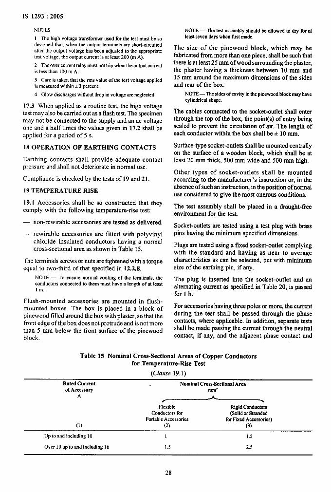
IS 1293:2005
NOTES
1 Thehigh voltage transformer used forthetestmust be sodesigned that, when the output terminrds are short-circuitedatler the output voltage has been adjusted to the appropriatetest voltage, the output current is at least 200 (m A).
2 Theovercurrentrelay mustnottripwherr theoutputcurrentis less than 100m A.
3 Care is taken that therms value of the test voltage appliedis measured within+ 3 percent.
4 Glow discharges without drop in voltage are neglected.
17.3 When applied as a routine test, the high voltage
test may also be carried out as a flash test. The specimenmay not be connected to the supply and an ac voltageone and a half times the values given in 17.2 shall beapplied for a period of 5 s.
18 OPERATION OF EARTHING CONTACTS
Earthing contacts shall provide adequate contactpressure and shall not deteriorate in normal use.
Compliance is checked by the tests of 19 and 21.
19 TEMPERATURE RISE
19.1 Accessories shall be so constructed that theycomply with the following temperature-rise test
— non-rewirable accessories are tested as delivered.
— rewirable accessories are fitted with polyvinylchloride insulated conductors having a normalcross-sectional area as shown in Table 15.
The terminals screws or nuts are tightened with a torqueequal to two-third of that specified in 12.2.8.
NOTE — To ensure normal cooling of the terminals, theconductorsconnectedto them must have a lengthof at least1m.
Flush-mounted accessories are mounted in flush-mounted boxes. The box is placed in a block ofpinewood tilled around the box with plaster, so that thefront edge of the box does not protrude and is not morethan 5 mm below the front surface of the pinewoodblock.
dNOTE — The test assembly should be allowed to dry for at ‘1
least seven days when first made. j.’~,
j
.[;:The size of the pinewood block, which may befabricated from more than one piece, shall be such thatthere is at least 25 mm of wood surrounding the plaster,the plaster having a thickness betsveen 10 mm and15 mm around the maximum dimensions of the sidesand rear of the box.
NOTE—Thesides of cavity in the pinewood block may havecylindrical shape.
The cables connected to the socket-outlet shall enterthrough the top of the box, the point(s) of entry being j$~
sealed to prevent the circulation of air. The length of it‘. $each conductor within the box shall be+ 10 mm.
‘;:-Iq
‘,, ,’
Surface-type socket-outlets shall be mounted centrally,.
,’
on the surface of a wooden block, which shall be at~,
least 20 mm thick, 500 mm wide and 500 mm high.
Other types of socket-outlets shall be mounted ~daccording to the manufacturer’s instruction or, in theabsence of such an instruction, in the position of normal ),, ,use considered to give the most onerous conditions.
\The test assembly shall be placed in a draught-fi-ee >#
environment for the test.
Socket-outlets are tested using a test plug with brasspins having the minimum specified dimensions.
Plugs are tested using a fixed socket-outlet complying.,,,
with the standard and having as near to average ‘,
characteristics as can be selected, but with minimumsize of the earthing pin, if any. ‘i
The plug is inserted into the socket-outlet and analternating current as specified in Table 20, is passed >for 1 h.
For accessories having three poles or more, the currentduring the test shall be passed through the phase .contacts, where applicable. In addition, separate testsshall be made passing the current through the neutralcontact, if any, and the adjacent phase contact and a
Table 15 Nominal Cross-Sectional Areas of Copper Conductorsfor Temperature-Rise Test
(Clause 19. 1)
Rated Current NominalCross-Sectional Areaof Accessory mm2 i
A\
Flexible Rigid ConductorsConductors for (Solid or Stranded
Portable Accessories for Fixed Accessories)(1) (2) (3)
Up to and including 10 1 1.5
Over 10 up to and including 16 1.5 2.5
28
through the earthing contact, if any, and the nearestphase contact. For the purpose of this test, earthingcontacts, irrespective of their number, are consideredas one pole.
In case of multiple and combined socket-outlets thetest is carried out on one socket-outlets of each typeand current rating.
The temperature is determined by means of meltingparticles, colour changing indicators or thermocouples,which are so chosen and positioned that they have anegligible effect on the temperature being determined.
The temperature-rise at the terminals shall not exceed45”C.
NOTES
1 For the purpose of the test of 25.3, the temperature-rise ofexternal parts of insulating material not necessary to retaincurrent-carrying parts and parts of the earthing circuit inposition, even though they are in contact with them, is alsodetermined.
2 In case of accessories incorporating dimmers, fuses,switches, energy regulators, etc, these other elements are short-circuited for the purpose of this test.
20 MAKING AND BREAKING CAPACITY
Accessories shall have adequate breaking capacity.
Compliance is checked by testing socket-outlets, andplugs with pins which are not solid, by means of anapparatus as shown in Fig. 12.
Rewirable accessories are fitted with’ conductors asspecified for the test of 19.
NOTE — In case of failure of the shutters, the tests onshuttered socket-outlets may be repeated with operationsmade by hand.
Socket-outlets are tested using a test plug with brasspins provided, if applicable, insulating sleeves, andhaving the maximum specified (dimension, with atolerance of Omm/O.06 mm, and spaced at the nominaldistance, with a tolerance of +0.05 mm; however, asfar as the extremities of the sleeves are concerned, itis sufficient that their dimensions are within thetolerances given in the relevant data sheets, if any.
NOTES
1 Dimensions of insulating sleeves are under consideration.
2 The shapes of the extremities of the insulating sleeves arenot considered of importance for the purpose of the testprovided that they are according to the relevant data sheets ifany.
3 The material of the_brass pins shall be as specified inIS 292 type Cu Zn 39 Pb2-M.
4 The micro-composition shall be homogeneous.
The ends of round pins are rounded.
Plugs are tested using a fixed socket-outlet complyingwith this standard and having as near to averagecharacteristics as can be selected.
29
IS 1293:2005
NOTE — Care is taken that the pins of the test plugs are ingood condition before the test is started.
The length of the stroke of the test apparatus shall bebetween 50 mm and 60 mm.
The plug is inserted into and withdrawn from the socket-outlet 50 times (100 strokes) at a rate of
— 30 strokes per minute
NOTE — A stroke is an insertion or a withdrawal of the plug.
The test voltage is 1.1 times the rated voltage and thetest currents are 1.25 times the rated current.
The periods during which the test current is passedfrom engagement of the plug until the subsequent
disengagement shall be: 1.5 + ~05s.
Accessories are tested using an alternating current(COS@= 0.6 * 0.05).
No current is passed through the earthing circuit, ifany.
The test is made with the connections shown in Fig. 40.
Resistors and inductors are not connected in parallel,except that, if an aircore inductor is used, a resistor,taking approximately 1 percent of the current throughthe inductor is connected in parallel with it.
Iron-core inductors may be used, provided the currenthas substantially sine-wave form.
Accessible metal parts, metal supports and any metalfiarne supporting the base of flush-type socket-outletsare connected through the selector switch C; for two-pole accessories, to one of the poles of supply for halfthe number of stroke, and to the other pole for theremainder.
In the case of multiple and combined socket-outlets,the test is carried out on one socket-outlet of each typeand current rating.
After the test, the samples shall show no damageimpairing their fhrther use and the entry holes for thepins shall not show any damage which may impair thesafety within the mean”mg of this standard.
21 NORMAL OPERATION
21.1 Accessories shall withstand the mechanical,electrical and thermal stresses occurring in normal usewithout undue wear or other harmfil effect.
Compliance is checked by testing socket-outlets, andplugs with resilient earthing socket-contacts or withpins which are not solid, by means of an appropriatetest apparatus, an example of which is shown inFig. 12.
The test pins (during socket-outlet test) and the fixed/socket-outlets (during the plug test for plugs withresilient earthing socket-outlets or with pins which are
1S 1293:2005
not solid) shall be replaced during-the test after 4500and 9000 strokes.
NOTE — In case of failure of the shutters, tests on shutteredsocket-outlet may be repeated performing the required numberof strokes (that is, 10000 strokes) with current flowing onsamples prepared by the manufactures without shutters, andby performing the same number of strokes without currenttlowing on samples provided with shutters or, as a third choice,with operations made by handas in normaluse.
Socket-outlets are tested using a test plug with brasspins provided, if applicable, with insulating sleeves,and having the maximum specified dfiensions, witha tolerance of -0.06 mm, and spaced at the nominal
distance with a tolerance of +0.05 mm, however, asfar as the extremities of the sleeves are concerned, itis sufficient that their dimensions are within thetolerances given in the relevant data sheet if any.
NOTES
1 Dimensionsof insulatingsleevesareunderconsideration.
2 The shapes of the extremities of the insulating sleeves arenot considered of importance for the purpose of the test.
3 The material of the brass pins shall be as specified in IS 292type CuZn 39 Pb2-M.
4 The micro-compositions shall be homogeneous.
The end of round pins is rounded.
NOTES
I Plugs are tested using a fixed socket-outlet complying withthis standard and having as near to average characteristics ascan be selected.
2 Care is taken that the pins of the test plugs are in goodcondition before the test is started.
The plug is inserted into and withdrawn from the socket-outlet 5000 times (10 000 strokes) at rate ofl
— 30 strokes per minute.
NOTE — A stroke is so insertion or a withdrawal of the plug.
The specimens are tested with an alternating currentas specified in Table 20, at rated voltage, in a circuitwith cos + = 0.8 * 0.05.
The test current is passed during each insertion andengagement of the plug.
The periods during which the test current is passedfrom engagement of the plug until subsequent shall
be: 1.5 + ~“5 s.
No current is passed through the earthing circuit if any.
The test is made with the connection indicated in 20,the selector switch C being operated as prescribedin 20.
In the case of multiple and combined socket-outletthe test is carried out on one socket-outlet of each typeand current rating.
During the test no sustained arcing shall occur.
After the test, the samples shall not-show:
—
—
—
—
—
wear impairiig their further use;
deterioration of enclosures, insulating linings orbarriers;
damage to the entry holes for the pins that mightimpair proper working;
loosening of electrical or mechanical connections;and
seepage of sealing compound.
For shuttered socket-outlets a gauge according toFig. 3 is applied to the entry holes corresponding tothe live contacts with a force up to 20 N and it is appliedsuccessively in three directions without withdrawingor rotating the gauge after each movement, and then asteel gauge according to Fig. 4 is applied with a forceup to 1 N and in three directions, with independentmovements (that is, withdrawing the gauge after eachmovement).
The gauges of Fig. 3 and Fig. 4 shall not touch liveparts when they remain under the relevant forces.
An electrical indicator, with a voltage not less than40 V and more than 50 V, is used to show contactwith the relevant part.
The specimens shall then comply with therequirements of 19, the test current being, however,equal to the test current required for the normaloperation test of the 21 and the temperature-rise, atany point, not exceeding 45”C, and they shall withstandan electric strength test made according to 17.2, thetest voltage, however, being reduced to 1500 V in thecase of accessories having a rated voltage of 250 Vand to 1 000 V in case of accessories having a ratedvoltage of 110 V.
NOTE — The humidity treatment as per 16.3, is not repeatedbefore the electric strength test of thk clause. The test of13.2 and 14.2 are made &the tests of tMs clause.
22 FORCE NECESSARY TO WITHDRAW THEPLUG
The construction of accessories shall allow the easyinsertion and withdrawal oft@ plug, and prevent theplug ffom work out of the socket-outlet in normal use.
For the purpose of this test, earthing contacts,irrespective of their number are considered as one pole.
Interlocked accessories are tested in the unlockedposition.
Compliance is checked, for socket-outlets-only by:
— a test to ascertain that the maximum forcenecessary to withdraw the test plug from thesocket-outlet is no higher than the force specifiedin Table 16.
— a test to ascertain that the minimum force necessaryto withdraw a single pin gauge ftom the individual
30
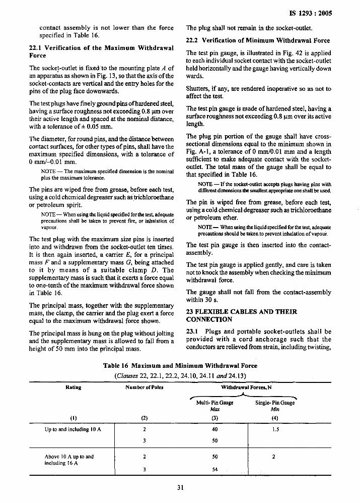
I
I
contact assembly is not lower than the forcespecified in Table 16.
22.1 Verification of the Maximum WithdrawalForce
The socke~-outlet is fixed “to the mounting plate A ofan apparatus as shown in Fig. 13, so that the axis of thesocket-contacts are vertical and the entry holes for thepins of the plug face downwards.
The test plugs have freely ground pins of hardened steel,having a surface roughness not exceeding 0.8pm overtheir active length and spaced at the nominal distance,with a tolerance of+ 0.05 mm.
The diameter, for round pins, and the distance betweencontact surfaces, for other types of pins, shall have themaximum specified dimensions, with a tolerance ofO mm/-O.Ol mm.
NOTE— The maximum specified dimension is the nominalplus the maximum tolerance.
The pins are wiped tlee from grease, before each test,using a cold chemical degreaser such as trichloroethaneor petroleum spirit.
NOTE— Whenusingthe liquidspecified for the test adequateprecautions shatl be taken to prevent tire, or inhalation ofvapour.
The test plug with the maximum size pins is insertedinto and withdrawn from the socket-outlet ten times.It is then again inserted, a carrier E, for a principalmass F and a supplementary mass G, being attachedto it by means of a suitable clamp D. Thesupplemen~ mass is such that it exerts a force equalto one-tenth of the maximum withdrawal force shownin Table 16.
The principal mass, together with the supplementarymass, the clamp, the carrier and the plug exert a forceequal to the maximum withdrawal force shown.
The principal mass is hung on the plug without joltingand the supplementary mass is allowed to fall from aheight of 50 mm into the principal mass.
IS 1293:2005
The plug shall not remain in the socket-outlet.
22.2 Verification of Mhimum Withdrawal Force
The test pin gauge, is illustrated in Fig. 42 is appliedto each individual socket contact with the socket-outletheld horizontally and the gauge having vertically downwards.
Shutters, if any, are rendered inoperative so as not toaffect the test.
The test pin gauge is made of hardened steel, having asurface roughness not exceeding 0.8 pm over its activelength.
The plug pin portion of the gauge shall have cross-sectional dimensions equal to the minimum shown inFig. A-1, a tolerance of O mm/O.O 1 mm and a lengthsufficient to make adequate contact with the socket-outlet. The total mass of the gauge shall be equal tothat specified in Table 16.
NOTE— If the socket-outletaccepts plugs having pins withdifferent dmensions the smallest appropriate one shall be used.
The pin is wiped free from grease, before each tes~using a cold chemical degreaser such as trichloroethaneor petroleum ether.
NOTE— When using the liquid specified for the tesL adequateprecautions should be taken to prevent inhalation of vapour.
The test pin gauge is then inserted into the contact-assembly.
The test pin gauge is applied gently, and care is takennot to knock the assembly when checking the minimumwithdrawal force.
The gauge shall not fall from the contact-assemblywithin 30s.
23 FLEXIBLE CABLES AND THEIRCONNECTION
23.1 Plugs and portable socket-outlets shall beprovided with a cord anchorage such that theconductors are relieved from strain, including twisting,
Table 16 Maximum and Minimum Withdrawal Force
(Ckmres 22,22.1,22.2,24.10,24.11 and 24.13)
Rating Number ofPoles Withdrawal Forces, N
~-“
Max A4in
(1) (2) (3) (4)
Up to and including 10A 2 40 1.5
3 50
Above 10A up to and 2 50 2including 16A
3 54
31
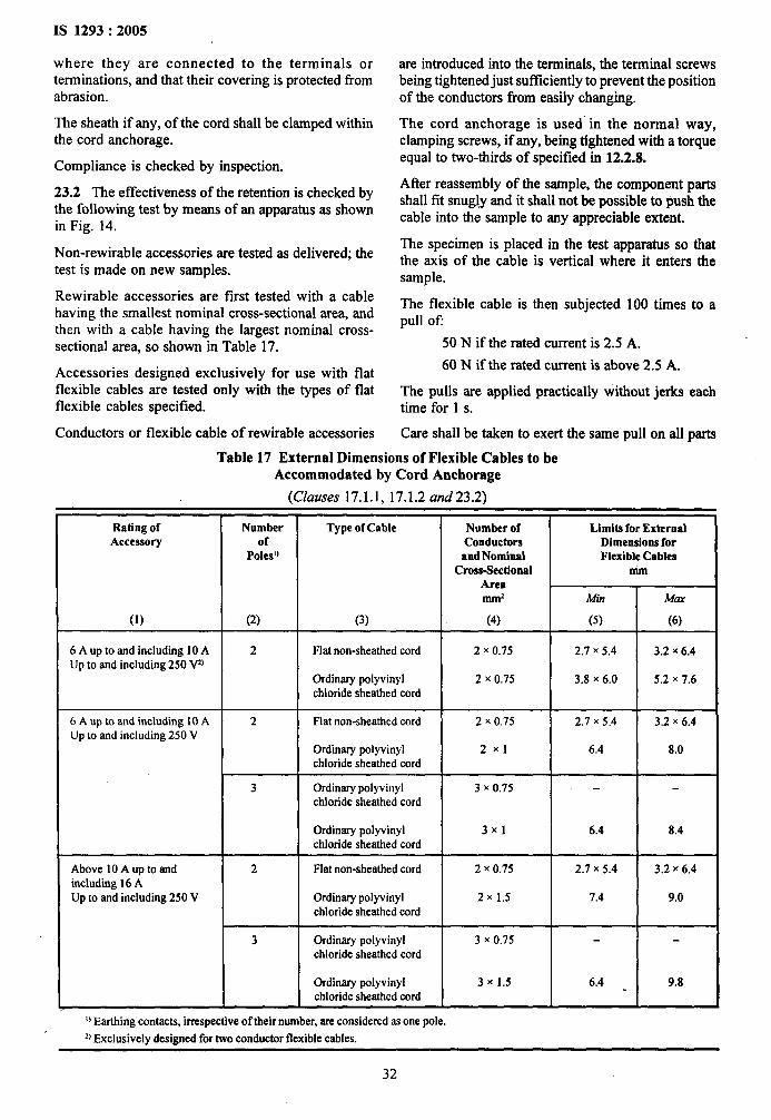
IS 1293:2005
where they are connected to the terminals orterminations, and that their covering is protected fromabrasion.
The sheath if any, of the cord shall be clamped withinthe cord anchorage.
Compliance is checked by inspection.
23.2 The effectiveness of the retention is checked bythe following test by means of an apparatus as shownin Fig. 14.
Non-rewirable accessories are tested as delivered; thetest is made on new samples.
Rewirable accessories are first tested with a cablehaving the smallest nominal cross-sectional area, andthen with a cable having the largest nominal cross-sectional area, so shown in Table 17.
Accessories designed exclusively for use with flatflexible cables are tested only with the types of flatflexible cables specified.
Conductors or flexible cable of rewirable accessories
Rating ofAccessory
(1)
6 A up to and including 10 AUp to and including 250 Vz)
6 A up to and including 10AUp to and including 250 V
Above 10A up to andincludhg 16AUp to and including 250 V
are introduced into the terminals, the terminal screwsbeing tightened just sut%ciently to prevent the positionof the conductors from easily changing.
The cord anchorage is used in the normal way,clamping screws, if any, being tightened with a torqueequal to two-thirds of specified in 12.2.8.
After reassembly of the sample, the component partsshall fit snugly and it shall not be possible to push thecable into the sample to any appreciable extent.
The specimen is placed in the test apparatus so thatthe axis of the cable is vertical where it enters thesample.
The flexible cable is then subjected 100 times to apull Ofi
50 N if the rated current is 2.5 A.
60 N if the rated current is above 2.5 A.
The pulls are applied practically without jerks eachtime for 1 s.
Care shall be taken to exert the same pull on all parts
Table 17 External Dimensions of Flexible Cables to beAccommodated by Cord Anchorage
(Clauses 17.1.1, 17.1.2 and 23.2)
Number Type of CabIeof
Poleal)
(2) (3)
2 Flat non-sheathed cord
Ordinary polyvinylchloride sheathed cord
2 Flat non-sheathed cord
Ordinary polyvinylchloride sheathed cord
3 Ordinary polyvinylchloride sheathed cord
Ordinary polyvinylchloride sheathed cord
2 Flat non-sheathed cord
Ordimuy polyvinylchloride sheathed cord
3 Ordinary polyvinylchloride sheathed cord
Ordinary polyvinylchloride sheathed cord
o Etilng contac~, irrespective of their number, are considered m one pole.
j)Exclusively designed for two conductor flexible cables.
Number ofConductorsand Nominal
Cross-SectionalArea-2
(4)
2 x ().75
2 x 0.75
2 x 0.75
2X1
3 x 0.75
3X1
2 x 0,75
2x 1.5
3 x 0.75
3 x 1.5
Limits for ExternalDimensions forFlexible Cables
MM
Afin Mm
2.7 x 5.4 I 3.2 x 6.4
3.8 x 6.0 I 5.2 x 7.6
2.7 x 5.4 3.2 x 6.4
6.4 8.0
6.4 8.4
2.7 x 5.4 3.2 x 6.4
7.4 9.0
6.4 9.8
32
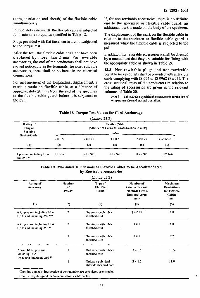
.’
(core, insulation and sheath) of the flexible cablesimultaneously.
Immediately afterwards, the flexible cable is subjectedfor 1 min to a torque, as specified to Table 18.
Plugs provided with flat tinsel cords are not subjectedto the torque test.
After the test, the flexible cable shall not have beendisplaced by more than 2 mm. For rewirableaccessories, the end of the conductors shall not havemoved noticeably in the terminals; for non-rewirableaccessories, there shall be no break in the electricalconnections.
For measurement of the longitudinal displacement, amark is made on flexible cable, at a distance ofapproximately 20 mm from the end of the specimenor the flexible cable guard, before it is subjected tothe pull.
IS 1293:2005
If, for non-rewirable accessories, there is no definiteend to the specimen or flexible cable guard, anadditional mark is made on the body of the specimen.
The displacement of the mark on the flexible cable inrelation to the specimen or flexible cable guard ismeasured while the flexible cable is subjected to thepull.
In addition, for rewirable accessories it shall be checkedby a manual test that they are suitable for fitting withthe appropriate cable as shown in Table 19.
23.3 Non-rewirable plugs and non-rewirableportable socket-outlets shall be provided with a flexiblecable complying with IS 694 or IS 9968 (Part 1). Thecross-sectional areas of the conductors in relation tothe rating of accessories are given in the relevantcolumns of Table 20. .
NOTE—Table20alsospecifies the test currents for the test oftemperature-rise and normal operation.
Table 18 Torque Test Values for Cord Anchorage
(Clause 23.2)
Rating of Flexible CablePlug or (Number of Cores x Cross-Section in mm’)
Portable ASocket-Outlet / %
2 x 0.5 2 x 0.75 3 x 0.5 3 ~ 0.75 2 or more X1
(1) (2) (3) (4) (5) (6)
Up to and including 16A 0.1Nm 0.15Nm 0.15Nm 0.25Nm 0.25Nmand 250 V
Table 19 Maximum Dimensions of Flexible CaMes to be Accommodatedby Rewirable Accessories
(Clause 23.2)
Rating of Number Type of Number of MaximumAccessory of Flexible Conductors and Dimensions
Poles]) Cable Nominal Cross- for FlexibleSectional Area Cables
~m2 mm
(1) (2) (3) (4) (5)
6 A up to and including10A 2 Ordinarytoughrubber 2 x 0.75 8.0Upto and including250 Vz) sheathedcord
6 A up to and including10A 2 Ordinarytoughrubber 2X1 8.8Upto and including250 V sheathedcord
3 Ordinarytoughrubber 3X1 9.2sheathedcord
Above 10A up to and 2 Ordinarytoughrubber 2x 1.5 10.5including 16A sheathed cordUpto and including250 V
3 Ordinarypolyvinyl 3 x 1.5 11.0chloridesheathedcord
i
.
I)Earthingcontacts,irrespectiveof theirnumber,areconsideredasone pole.4 Ex~lusivelvdesignedfor~o conductorflexiblecab]es.
33

1S 1293:2005
Table 20 Relationship Between Ratings of Accessories, Nominal Cross-SectionalAreas. of Test Conductors and Test Currents for the Tests of
Temperature-Rise and Normal Operation
(Clauses 19.1 and 23.3)
Rating Rewirable Fixedof Accessories
Accessory Test Current
&
(1)
19 21
(2) (3)
Rewirable PortableSocket-OutletsTest Current
&Clause
19 21
(4) (5)
Non-rewirable PortableTest CurrentCross-Section
A
~ml 19 .21
(6) (7) (8)
Ncm-rewirable PlugsTest CurrentCross-Section
A
~m2 19 21
(9) (lo) (11)
Tinsel 1 1
2.5 A — — 0.5 2.5 2.5
llOV/250V 0.75 4’ 2.5
1 4 2.5
Tinsel 1 1
6A 9 6 8.4 6 — — 0.5 2.5 2.5 I;
llOV/250V 0.75 9 6 w1 9 6 - %?~,
#
10A 0.75 10 10 0.5 2.5 2.5
llOV/250V 16 10 14 10 1 12 10 0.75 10 10
1.5 16 10 1 12 10
Tinsel 1 1
16A 1 12 12 0.5 2.5 2.5
110V/250V 22 16 20 16 1.5 16 16 0.75 10 10
1 12 12
1.5 16 16
NOTES
1 Tinselcords and flexible cables having a cross-sectional area of 0.5 mmzare,allowed in lengthsup to 2 m only.
2 Plugs incorporated in cord sets are tested as specified in this standard.
3 The test currents for accessories having other rated currents are determined by interpolation between the next lower and the nexthigher standard ratings except that for 19 test currents for rewirable portable accessories, which are obtained as follows:
for InS 10A test current= 1.4In
for In> 10A test current = 1.25 In
Flexible cables shall have the same number ofconductors as there are poles in the plug or socket-outlet, earthing contacts, if any, being considered asone pole, irrespective of their number. The conductorconnected to the earthing contact shall be identifiedby the colour combination greenlyellow.
Compliance is checked by inspection, by measurementand by checking that the flexible cables are inaccordance with IS 694 or IS 9968 (Part 1), asapplicable.
23.4 Non-rewirable plugs and non-rewirable socket-outlets shall be so designed that the flexible cable is
. protected against excessive bending where h enters
the accessoxy. Guards provided for this purpose shallbe of insulating material and shall be fixed in a reliablemanner.
NOTE — Helieal metal springs, whether bare or covered withinsulating material, shall not be used as cord guards.
Compliance is checked by inspection and by a flexingtest made by means of an apparatus as shown inFig. 15.
The test is made on new specimens. ,
The specimen is f~ed to the oscillating member ofthe apparatus so that, when this is at the middle of itstravel, the axis of the flexible cable, where it enters
34
the specimen, is vertical and passes through the axisof oscillation.
Specimens with flat cords are mounted so that the majoraxis of the section is parallel to the axis of oscillation.
The accessory shall be fixed in the test apparatus in thefollowing way:
— Plugs: by the pins
— Portable socket-outlet: at a distance of 4 mm to5 mm (provisional values) in the direction of theflexible cable, from the engagement face; a test plughaving the maximum dimensions shall be insertedin the portable socket-outlets during the test.
The accessory is, by variation of the distance betweenthe fixing part of the oscillating member and the axisof oscillation, so positioned that the flexible cablesmakes the minimum lateral movement when theoscillating member of the test apparatus is moved overits full travel.
NOTES
I In order to have the possibility of finding easily byexperiment the mounting position with the minimum lateralmovement of the flexible cable during the tes~ the flexingapp~atus shall be built in such a way that the diffe~nt supportsfor the accessories mounted on the oscillating member can bereadily adjusted.
2 It is recommended to have a device (for example, a slot ora pin) to see whether the flexible cable makes the minimtimlateral movement,
The flexible cable is loaded with a mass such that theforce applied is:
— 20 N for accessories with flexible cables having anominal cross-sectional area exceeding 0.75 mmz.
— 10 N for other accessories.
A current equal to the rated current of the accessoryor the following current, whichever is the lower, ispassed through the conductors:
— 16A for accessories with flexible cables having anominal cross-sectional area exceeding 0.75 mm2.
— 10A for accessories with flexible cables having anominal cross-sectional area of 0.75 mm2.
2.5 A for accessories with flexible cables havinga nominal cross-sectional area less than 0.75 mm2.
The voltage between the conductors is equal to therated voltage of the sample.
The oscillating member is moved through an angle ofX“ (45° on either side of the vertical), the number offlexing being 10000 and the rate of flexing 60per minute.
NOTE — A flexing is one movemen~either backwards orforwards.
IS 1293:2005
Specimens with circular section flexible cables areturned through 90° in the oscillating member after5000 flexing, specimens with flat flexible cables areonly bent in a direction perpendicular to the planecontaiiting the axes of the conductors.
During the flexing test, there shall be:
a) no interruption of the current and
b) no short-circuit between conductors.
NOTE—Ashort-circuitbetweentheconductorsof theflexiblecable is considered to occurif the current attains a value equalto twice the test current of the accessory.
The voltage drop between each contact and thecorresponding conductor, with a test current flowinghaving a value as prescribed for 21, shall not exceed10 mV.
After the test the guard, if any, shall not have separatedfrom the body and the insulation of the flexible cableshall show no sign of abrasion or wew, broken strandsof the conductors shall not have pierced the insulationso as to become accessible.
24 MECHANICAL STRENGTH
Accessories, surface mounting boxes and screwedglands shall have adequate mechanical strength towithstand the stresses imposed during installation anduse.
Compliance is checked by the appropriate testsof 24.1 to 24.13 as follows:
— for fixed socket-outlets 24.1 and 24.3
— for portable single socket-outlets:
● with enclosures, covers or bodies 24.2other than thermoplastic orelastomeric material
● with enclosures, covers or 24.2,24.4 andbodies of elastomeric or 24.5thermoplastic material
— for portable multiple and combined socket-outlets:
“ with enclosures, covers or bodiesother than elastomeric orthermoplastic material
● with enclosures, covers orbodies of elastomeric orthermoplastic material
— for plugs:
● with enclosures, covers or bodiesother than elastomeric orthermoplastic material
“ with enclosures, covers or bodiesof elastomeric or thermoplasticmaterial
35
24.9
24.4 and 24.9
24.2 and24.10
24.2,24.4,24.5 and
24.10
:.
1
.
‘4
IS 1293:2005
— forscrewed glands of accessories 24.6other than ordinary
— forplug pins provided with insulating 24.7
sleeves
— forshuttered socket-outlets 24.8
— forsurface mounting boxes 24.1
— forportable socket-outlets having 24.11means for suspension on a wall 24.12 and
24.13
24.1 The specimens are subjected to blows by meansof an impact-test apparatus as shown in Fig. 16, 17,18 and 19.
The striking element has a hemispherical face of10 mm radius of polyamide having a Rockwellhardness of HR 100, and has a mass of 150 + 1 g.
It is rigidly fixed to the lower end of a steel tube withan external diameter of 9 mm and a wall thickness of0.5 mm, which is pivoted at its upper end in such away that it swings only in a vertical plane.
The axis of the pivot is 1000 + 1 mm above the axis ofthe striking element.
The Rockwell hardness of the polyamide strikingelement is determined by using a ball having adiameter of 12.700 + 0.0025 mm. The initial loadbeing 100 + 2 N and the extra load 500+ 2.5 N.
The design of the apparatus is such that a force between1.9 N and 2.0 N has to be applied to the face of thestriking element to maintain the tube in a horizontalposition.
The specimens are mounted on a sheet of plywood,8 mm thick and 175 mm square, secured at its top andbottom edges to a rigid bracket which is part of themounting support.
Portable multiple socket-outlets are tested as fixedsocket-outlets but they are fixed to the plywood sheetby auxiliary means. ,
The mounting support shall have a mass of 10 + 1 kgand shall be mounted on a rigid tlarne by means ofpivots. The frame is fixed to a solid wall.
The design of the mounting is such that:
—
—
—
—
the specimen can be so placed that the point ofimpact lies in the vertical plane through the axisof the pivot;
the specimen can be removed horizontally andturned about an axis perpendicular to the surfaceof the plywood;
the plywood can be turned 60°, in both directionsabout a vertical axis.
surface-type socket-outlets and surface mountingboxes are mounted on the plywood as in normaluse.
36
Inlet openings which are not provided, with knock-outs, are left open; if they are provided with knock-outs, one of them is opened.
Flush-type socket-outlets are mounted in a recessprovided in a block of hornbeam or material havingsimilar mechanical characteristics, which is fixed to asheet of plywood and not in its relevant mounting box.
If wood is used for the block, the direction of the woodfibres must be perpendicular to the direction of theimpact.
Flush-type screw fixing socket-outlets shall be fixedby means of screws to lugs recessed in the hornbeamblock. Flush-type claw fixing socket-outlets shall befixed to the block by means of the claws.
Before applying the blows, fixing screws of bases andcovers are tightened with a torque equal to two-third ofthat specified in Table 6.
The specimens are mounted so that the point of impactlies in the vertical plane through the axis of the pivot.
The striking element is allowed to fall from a heightwhich is specified in Table 21.
The impact energy determined by the part of thespecimen which projects most from the mountingsurface is applied on all parts of the specimen, withthe exception of parts A.
The height of fall is the vertical distance between theposition of a checking point when the pendulum isreleased, and the position of that point at the momentof impact. The”checking point is marked on the surfaceof the striking element where the line through the pointof intersection of the axes of the steel tube of thependulum and the striking element and perpendicularto the plane through both axes, meets the surface.
The specimens are subjected to blows, which areevenly distributed. The blows are not applied to“knock-outs”.
The following blows are applied:
— for parts A, five blows :
● One blow in the centre, after the specimen hasbeen moved horizontally; one each on theunfavorable points between the centre and theedges and then, after the specimen has been turned90° about its axis perpendicular to the plywood,one each on similar points;
— for parts B (as far as applicable), C and D fourblows:
● Two blows on each of the other two sides of thespecimen on which blows can be applied after thespecimen has been turned 90° about its axisperpendicular to the plywood sheet has beenturned 60° in each of the opposite directions;
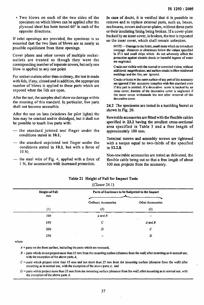
● Two blows on each of the two sides of thespecimen on which blows can be applied after theplywood sheet has been turned 60° in each of theopposite directions.
If inlet openings are provided, the specimen is somounted that the two lines of blows are as nearly aspossible equidistant from these openings.
Cover plates and other covers of multiple socket-outlets are treated as though they were thecorresponding number of separate covers, but only oneblow is applied to any one point.
For socket-outlets other than ordinary, the test is madewith lids, if any, closed and in addition, the appropriatenumber of blows is applied to these parts which areexposed when the lids are open.
After the test, the samples shall show no damage withinthe meaning of this standard. In particular, live partsshall not become accessible.
After the test on lens (windows for pilot lights) thelens may be cracked and/or dislodged, but it shall notbe possible to touch live parts with:
—
—
—
the standard jointed test finger under theconditions stated in 10.1;
the standard unjointed test finger under theconditions stated in 10.1, but with a force of10 N;
the steel wire of Fig. 4, applied with a force of
IS 1293:2005
In case of doubt, it is verified that it is possible toremove and to replace external parts, such as, boxes,enclosures, covers and cover-plates, without these partsor their insulating lining being broken. If a cover-platebacked by an inner cover, is broken, the testis repeatedon the inner cover, which shall remain unbroken.
NOTE—Damagetothefinish,small dents which do not reducecreepage distances or clearances below the values specifiedin 27.1 and small chips which do not adversely affect theprotection against electric shock or harmful ingress of waterare neglected.
Cracks not visible with the normal or corrected vision, withoutadditional magnification, and surface cracks in fibre reinforcedmoldlngs and the like, are ignored.
Cracks or holes in the outer surface of any part of the accessoryarc ignored if the accessory complies with this standard evenif this part is omitted. If a decorative cover is backed by aninner cover, fractureof the decorativecover is neglected ifthe inner cover withstands the test after removal of thedecorativecover.
24.2 The specimens are tested in a tumbling barrel asshown in Fig. 20.
Rewirable accessories are fitted whh the flexible cablesspecified in 23.2 having the smallest cross-sectionalarea specified in Table 3 and a free length ofapproximately 100 mm.
Terminal screws and assembly screws are tightenedwith a torque equal to two-thirds of the specifiedin 12.2.8.
Non-rewirable accessories are tested as delivered, theflexible cable being cut so that a free length of about
1 N, for accessories-with kcreased protection. 100 mm projects from the accessory.
Table 21 Height of Fall for Impact Tests
(Clause 24. 1)
Height of Fall Parts of Enclosure to be Subjected to the Impactmm
/
Ordinary Accessories Other Accessories
(1) (2) (3)
100 Aarrd B
150 c Asmd B
200 D c
250 D
where
A = parts on the front surface, including the parts which are recessed;
B =parts which do not project more than 15mm from the mounting surface (distance tlom the watl) after mounting as in normal use,with the exception of the above parts A;
C = parts which project more than 15 mm and not more than 25 mm from the mounting surface (distance horn the wall) aftermounting as in normal use, with the exception of the above parts A; and
D = parts which project more than 25 mm from the mounting surface (distance from the wall) atlcr mounting as in normat use, withthe exception of the above parts A.
.“
,,
.
37
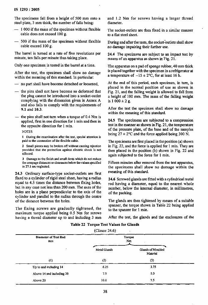
IS 1293:2005
The specimens fall from a height of 500 mm onto asteel plate, 3 mm thick, the number of falls being.
— 1000 if the mass of the specimen without flexiblecable does not exceed 100 g.
— 500 if the mass of the specimen without flexiblecable exceed 100 g.
The barrel is turned at a rate of five revolutions perminute, ten falls per minute thus taking place.
Only one specimen is tested in the barrel at a time.
After the test, the specimen shall show no damagewithin the meaning of this standard. In particular:
— no part shall have become detached or loosened,
— the pins shall not have become so deformed thatthe plug cannot be introduced into a socket-outletcomplying with the dimension given in Amex Aand also fails to comply with the requirements of9.1 and 10,3.
— the pins shall not turn when a torque of 0.4 Nm isapplied, fmt in one dmection for 1 min and then inthe opposite direction for 1 min.
NOTES
1 During the examination&r the test, specialattentionispaid to the connectionof the flexible cable.
2 Small pieces maybe broken off without causing rejectionprovided that the protection against electric shock is notaffected.
3 Darnage to the finish and small dents which do not reducethe creepage distances or clearances below the values specifiedin 27.1 are neglected.
24.3 Ordinary surface-type socket-outlets are fustfixed to a cylinder of rigid steel sheet, having a radiusequal to 4.5 times the distance between f~irtg holes,but in any case not less than 200 mm. The axes of theholes are in a plane perpendicular to the axis of thecylinder and parallel to the radius through the centreof the distance betxveen the holes.
The fixing screws are gradually tightened, themaximum torque applied being 0.5 Nm for screwshaving a thread diameter up to and including 3 mm
and 1.2 Nm for screws having a larger threaddiameter.
The socket-outlets are then fixed in a similar mannerto a flat steel sheet.
During and afler the tests, the socket~outlets shall showno damage impairing their further use.
24.4 The specimens are subject to an impact test bymeans of an apparatus as shown in Fig. 21.
The apparatus on a pad of sponge rubber, 40 mm thickis placed together with the specimen in a refrigerator ata temperature of –15 * 2“C, for at least 16 h.
At the end of this period, each specimen, in turn, isplaced in the normal position of use as shown inFig. 21, and the falling weight is allowed to fall froma height of 100 mm. The mass of the falling weightis1000+2g.
After the test the specimen shall show no damagewithin the meaning of W standard.
24.5 The specimens are subjected to a compressiontest in the manner as shown in Fig. 21, the temperatureof the pressure plate, of the base and of the samplesbeing 27+ 2°C and the force applied being 300 N.
The specimens are ftrst placed in the position(a) showriin Fig. 22, and the force is applied for 1 min. They arethen placed in the position (b) shown in Fig. 22 andagain subjected to the force for 1 min.
Fifteen minutes after removal fkom the test apparatus,the specimens shall show no damage within themeaning of this standard.
24.6 Screwed glands are fitted with a cylindrical metalrod having a diameter, equal to the nearest wholenumber, below the internal diameter, in millimetres,of the packing.
The glands are then tightened by means of a suillablespanner, the torque shown in Table 22 being appliedto the spanner for 1 min.
After the test, the glands and the enclosures of the
Table 22 Torque Test Values for Glands
(Clause 24.6) .
Diameter of Test Rod Torquemm
~Metal Glands Glandsof Moulded
Material
(1) (2) (3)
Up to and including 14 6.25 3.75
Above 14and including20 7.5 5.0
Above 20 10.0 7.5
38
specimens shall show no damage within the meaningof this standard.
24.7 Plug pins provided with insulating sleeves aresubjected to the following test by means of an apparatusas shown in Fig. 23.
The test apparatus comprises a horizontally disposedbeam, which is pivoted about its centre point. A shortlength of steel wire, 1 mm in diameter and bent into a Ushape, the base of the U being straight, is rigidlyattached, at both ends, to one end of the beam, so thatthe straight part projects below the beam and is parallelto the axis of the beam pivot.
The plug is held in a suitable clamp in such a positionthat the straight part of the steel wire rests on the plugpin, at right angles to it. The pin slopes downwards atan angle of 10° to the horizontal.
The beam is loaded so that the wire exerts a force of4 N on the pin.
The plug is caused to move backwards and forwards ina horizontal direction in the plane of the axis of thebeam, so that the wire rubmdong the pin. The length ofpin thus abraded is approximately 9 mm, of whichapproximately 7 mm is over the insulating sleeve. Thenumber of movements is 20000 (10 000 in eachdirection) and the rate of operation is 30 movementsper min.
The test is made on one pin of each specimen.
After the test, the pins shall show no damage whichmay affect safety or impair the fimther use of the plug,in particular, the insulating sleeve shall not havepunctured or rucked up.
24.8 Shuttered socket-outlets shall have the shutterso designed that it withstands the mechanical forcewhich may be expected in normal use, for example,when a pin of a plug is inadvertently forced againstthe shutter of a socket-outlet entry hole.
Compliance is checked by the following test, whichis carried out both on specimens which have beensubmitted to the test according to 21, without andwith previous treatment as in 16.1.
One pin from a plug of the same system is appliedfor 1 min with a force of 40 N against the shutter of anentry hole in a direction perpendicular to the tlontsurface of the socket-outlet.
For shutters provided as the only means to preventsingle pole insertion, the force shall be 75 N insteadof40 N.
Where the socket-outlet is designed to accept plugsof different types, the test is made with a pin fi-om aplug with the largest size pin.
The pin shall not come in contact with live parts.
39
IS 1293:2005
An electrical indicator with a voltage not less than40 V and not more than 50 V is used to show contactwith the relevant part.
After the test, the specimens shall show no damagewithin the meaning of this standard.
NOTE—Small dents on the surface, which does not adverselyaffect further use of the socket-outleL are neglected.
24.9 Rewirable multiple portable socket-outlets arefitted with the lightest type of flexible cable of thesmallest cross-sectional area specified in Table 3.
The free end of the cable is fixed to a wall at a height of750 mm above the floor, as shown in Fig. 24.
The specimen is held so that the flexible cable ishorizontal and then it is allowed to fall on to a concretefloor, eight times, the cable being rotated through 45°at its fixing between each time.
After the test, the specimens shall show no damagewithin the meaning of this standard, in particular, nopart shall have become detached or loosened.
Accessories other than ordinary ones shall be submittedagain to the relevant test as specified in 16.2.
Small chips and dents which do not adversely affectthe protection against electric shock or harmful ingressof water are neglected.
24.10 The plug is placed on a rigid steel plate providedwith holes suitable for the pins of the plug as shownas an example in Fig. 25.
The distances between the centres of the holes (for
example, d, and dz) shall be the same as the distancesbetween the centres of the circle circumscribed aroundthe cross-sectional area of each pin as given inAnnex A for plugs.
Each hole shall have a diameter equal to that of thecircle circumscribed around the cross-sectional areaof the pin plus 6 mm + 0.5 mm.
The plug is to be so positioned on the steel plate thatthe centres of the circles circumscribing the pinscoincide with the centres of the holes.
A pull on equal to the maximum withdrawal force asgiven in Table 16 is applied, without jerks, for 1 minor each pin in turn, in the direction of the longitudinalaxis of the pin.
A pull is applied within a heating cabinet at atemperature of 70 + 2°C. One hour after the plug hasbeen placed in the heating cabinet.
After the test, the plug is allowed to cool down toambient temperature and then no pin shall have beendisplaced in the body of the plug more than 1 mm.
The test is made on new specimens.
.“
IS 1293:2005
24.11 Barriers, between the space intended for thesuspension means fixed to the wall and the live parts,likely to be subjected to mechanical strain when theportable socket-outlet is suspended on a wall, are testedas follows:
A cylindrical steel rod, having a diameter of 3 mm anda hemispherical end with radius of 1.5 mm, is pushedperpendicular to the supporting wall surface, in the mostunfavorable position, for 10s against the barrier, theforce being equal to 1.5 times the maximum plugwithdrawal force (as specified in Table 16).
The rod shall not pierce the barrier.
24.12 The portable socket-outlet mounted withsupply flexible cable is suspended on the wall asin normal use, by means of a cylindrical steel rodhaving the same dimensions as the rod describedin 24.11 and a length sufficient to touch the rear of thebarrier.
A pull equal to the force prescribed in 23.2 for checkingthe cord anchorage is applied, in the most unfavorableposition, to the supply flexible cable for 10 s. Duringthe test, the portable socket-outlet means for suspensionon a wall shall not break or, if they break, liveparts shall not become accessible to the standard testfinger.
24.13 The portable socket-outlets is suspended on thewall as in normal use, using a round head screw withshank diameter of 3 mm, and is subjected to a pulltest with the maximum withdrawal force specified, forthe corresponding plug, as specified in Table 16applied without jerks.
The pull force is applied for 10s perpendicular to theengagement face of the socket-outlet giving the greateststrain on the suspension means.
During the test, the portable socket-outlets means forsuspension on a wall shall not break in a way whichallows live parts to become assessable to the standardtest finger.
NOTE— The test of 24.11,24.12 and 24.13 am carried outon each means for suspension,in the case of more than onemeans.
24.14 When testing the forces necessary forcovers or, cover-plates to come off or not to come off,the socket-outlets are mounted as for normal use,flush-type socket-outlets are fixed in appropriatemounting boxes, which are installed as for normal useso that the rims of the boxes are flush with the walls,and the covers or cover-plates are fitted. If the coveror cover-plates are provided with locking means whichcan be operated without the aid of a tool, these meansare unlocked.
Compliance is then checked according to 24.14.1and 24.14.2 (see 13.7.2).
24.14.1 Verification of the Non-removal of Covers orCover-Plates
Forces are gradually applied in directions perpendicularto the mounting surfaces, in such away that the resultingforce acting on the centre of the covers, cover-plates,or parts of them is respectively:
— 40 N, for covers, cover-plates or parts of themcomplying with the tests of 24.17 and 24.18, or
— 80 N, for other covers, cover-plates or parts of them.
The force is applied for 1 min. The covers or cover-plates shall not come off.
The test is then repeated on new specimens, the coveror cover-plate is fitted on the wall after a sheet of hardmaterial, 1 mm+ 0.1 mm thick, has been fitted aroundthe supporting t%ne as shown in Fig. 8.
NOTE—The sheet of hard material is used to simulate wallpaper and may consist of a number of pieces.
After the test the specimens shall show no damagewithin the meaning of this standard.
24.14.2 Verijkation ~%iemovak+tiers orCover-Plates .
A force not exceeding 120 N is gradually applied, indirections perpendicular to the mounting supportingsurfaces, to covers, cover-plates, or parts of them bymeans of a hook placed. in turn in each of the grooves,holes, spaces or the like, provided for removing them.
The cover or cover-plates shall come off.
The test is made 10 times to each separable part, thefixing of which is not dependant on screws (equallydistributing as far as practicable the application points)the removal force is applied each time to the differentgrooves, holes or the like provided for removing theseparable part.
The test is then repeated on new specimens, the coveror cover-plate is fitted on the wall afier a sheet of hardmaterial, 1 mm+ 0.1 mm thick, has been fitted aroundthe supporting frame, as shown in Fig. 8.
After the tes$ the samples shall show no damage withinthe meaning of this standard.
24.15 The test is made as described in 24.14, butapplying, for 24.14.1, the following forces:
— 10 N, for covers or cover-plates complying withthe test of 24.17 and 24.18.
— 20 N, for other covers or cover-plates.
26.16 The test is made as described in 24.14, butapplying, for 24.14.1, the force of 10 N for all coversor cover-plates.
24.17 The gauge shown in Fig. 7 is pushed towards
40
I
I,!
1.
1,
each side of each cover or cover-plates which is fixedwithout screws on a mounting or supporting surfaces,as shown in Fig. 9. The face B resting on the mounting/supporting surface, with the face A perpendicular toit, the gauge is applied at right angle to each side undertest.
In the case of a cover or cover-plate freed withoutscrews to another cover, or cover-plate or to a mountingbox, having the same outline dimensions, the face Bof the gauge shall be placed at the same level as thejunction; the outline of the cover or cover-plate shallnot exceed the outline of the supporting surface.
The distances between the face C of the gauge and theoutline of the side tider test, measured parallel to faceB, shall not decrease (with the exception for grooves,holes, reverse tapers or the like, placed at a distanceless than 7 mm from a plane including face B andcomplying with the test of 24.18) when measurementsare repeated starting from point x in the direction ofthe arrow y (see Fig. 10).
24.18 A gauge according to Fig. 5, applied with a forceof 1 N shall not enter more than 1.0 mm from the upperpart of any groove, whole or reverse taper or the likewhen the gauge is applied parallel to the mounting/supporting surface and at right angle to the part undertest, as shown in Fig. 11.
NOTE— Verificationas to whether the gauge according toFig. 5 has entered more than 1.0 mm is made with reference toa surface perpendicular to face B and including the upperpart of the outtine of the grooves, holes, reverse tapers or thelike.
25 RESISTANCE TO HEAT
Accessories and surface mounting boxes shall beresistant to heat.
Compliance is checked by:
a) for surface mounting boxes, separable covers,separable cover-plates and separable frames, bythe test of 25.3;
b) for portable accessories, with the exception ofthe parts, if any, covered by (a), by the tests of25.1,25.4 and with the exception of accessoriesmade from natural or synthetic rubber or amixture of both, 25.3;
c) for fixed socket-outlets, with the exception ofthe parts, if any covered by (a), by the tests of25.1, 25.2 and with the exception of fixedsocket-outlets made from natural or syntheticrubber or a mixture of both, 25.3.
Parts intended only for decorative purposes, such as,certain lids, are not submitted to this test.
25.1 The specimen is kept for 1 h in a heating cabinetat a temperature of 100 + 2°C.
During the test, they shall not undergo any change
IS 1293:2005
irnpairing their further use, and sealing compound, ifany, shall not flow to such an extent that live parts areexposed.
After the test, the samples are then allowed to cooldown to approximately room temperature. There shallbe no access to live parts which are normally notaccessible when the specimens are mounted as innormal use, even if the standard test finger is appliedwith a force not exceeding 5 N are mounted as fornormal use.
Afler the tes~ marking shall still be legible.
Discoloration, blisters or slight displacement of thesealing compound is disregarded, provided that safetyis not impaired within the meaning of this standard.
25.2 Parts of insulating material necessary to retaincurrent-camying parts of the earthing circuit in position,and parts of the front surface zone of thermoplasticmaterial of 2 mm width surrounding the phase andneutral pin entry holes of socket-outlets, shall besubjected to a ball-pressure test by means of theapparatus as shown in Fig. 27, except that insulatingparts necessary to retain the earthing terminal inposition in a box, shall be tested as specified in 25.3.
NOTE — When it is not possible to cany out the test on thesample under tes~ the test shall be carried out on a piece cutout of thesampleandat least2 mmthick.If this isnotpossible,up to and including four layers, each cut out of the samespecimensample, may be used, in which case the total tMcknessof the layers shall be not less than 2.5 mm.
The part under test shall be placed on a steel plate atleast 3 mm thick and in direct contact with it.
The surface of the part to be tested is placed in thehorizontal position and a steel ball of 5 mm diameteris pressed against this surface with a force of 20 N.
The test load and the supporting means shall be placedwithin the heating cabinet for suftlcient time to ensurethat they have attained the stabilized testingtemperature before the test commences.
The test is made in a heating cabinet at a temperatureof 125 + 2°C.
After 1 h, the ball shall be removed from the specimen,which is then immersed, in cold water for cooling downwithin 10 s, to approximately room temperature.
The diameter of the impression caused by the ball ismeasured and shall not exceed 2 mm.
25.3 Parts of insulating material not necessary to retaincurrent-carrying parts and parts of the earthing circuitin position, even though they are in contact withthem, are subjected to a brdl-pressure test in accordancewith 25.2, but the test is made at a temperature of70+ 2°C or 40 + 2°C plus the highest of temperature-rise determined for the relevant part during the testof 19, whichever is the higher.
.
+9
41
IS 1293:2005
25.4 The specimens are subjected to a compression (rendering theuseof the appropriate screwdrivertest by means of an apparatus as shown in Fig. 28, the impossible), threads, washers or stirrups.test being made in a heating cabinet at a temperature NOTESof 80 + 2°C. 1 Screwsor nuts which are operated when connecting up
The apparatus comprises two steel jaws, having a accessoriesincludescrewsfor ~xing covers or cover PI-*s,
cylindrical face of 25 mm radius, a width of 15 mmetc.,but not connectingmeans for screwedconduits and screwfor fixing the base of a freed socket-outlet.
and a length of 50 mm. The length of 50 mm can be2 Theshapeof the bladeof the test screwdrivermustmatch
increased, depending on the size of the accessory to the head of the screw to be tested. The screws and nuts mustbe tested. not be tightenedinjerks. Damage to covers is ignored.
The comers are rounded with a radius of 2.5 mm. 3 Screwedconnectionsare consideredas partiallycheckedby the test of 21 and 24.
The specimen is clamped between the jaws in such away that these press against it in the area where it is 26.2 For screws in engagement with a thread of
gripped in normal use, the centre line of the jaws insulating material and which are operated when
coinciding as nearly as possible with the centre of this mounting the accessory during the installation, their
area. The force applied through the jaws is 20 N. correct introduction into the screw hole or nut shall beensured.
After 1 h, the jaws are removed and the samples shallshow no damage within the meaning of this standard. Compliance is checked by inspection and by manual
test.26 SCREWS, CURRENT-CARRYING PARTSAND CONNECTIONS
NOTE— Therequirementwithregardto correctintroductionis met if introduction of the screw in a slanting manner is
26.1 Connections, electrical or mechanical, shallpreventet for example, by guiding the screw by the part to befixed, by a recess in the female thread or by the use of a screw
withstand the mechanical stresses occurring in normal with the letilng thread removed.use.
Mechanical connection to be used during installationof accessories may be made using thread-formingtapping screws or thread-cutting tapping screws onlywhen the screws are supplied together with the piecein which they are intended to be inserted. In addition,thread-cutting screws intended to be used duringinstallation shall be captive with the relevant part ofthe accessory.
Screws or nuts which transmit contact pressure shallbe in engagement with a metal thread.
Compliance is checked by inspection and, for screwsand nuts transmitting contact pressure or which areoperated when connecting up the accessory, by thefollowing test.
NOTE— The requirementsfor the verification of terminalsare given in 12.
The screw or nuts are tightened and loosened:
— 10 times for screws in engagement with a threadof insulating material and for screws of insulatingmaterial.
— 5 times in all other cases.
Screws or nuts in engagements with a thread ofinsulating material and screws of insulating materialare completely removed and reinserted each time.
26.3 Electrical connecting shall be so designed thatcontact pressure is not transmitted through insulatingmaterial other than ceramic, pure mica or othermaterial with characteristics no less suitable, unlessthere is sufllcient resiliency in the metallic parts tocompensate for any possible shrinkage or yielding ofthe insulating material.
This requirement does not preclude designs with flattinsel cord where the contact pressure is obtained frominsulating parts having such properties as to ensurereliable and permanent contact under all conditionsof normal use, especially in view of shrinking, ageingor cold flow of the insulating part.
Connections made by insulation piercrng of tinsel cordshall be reliable.
Compliance is checked by inspection and, for the lastrequirement, by a test, which is under consideration.
NOTE-ThesuitaWity of the material is considered in respctof the stdility of the dimensions.
26.4 Screws and rivets, which serve as electrical aswell as mechanical connections, shall be locked againstloosening and/or turning.
Compliance is checked by inspection and manual test.
NOTES
The test is made by means of a suitable screwdriver or 1 Springwashersmayprovidesatisfactorylocking.
a suitable tool, applying a torque as specified in 12.2.8. 2 For rivets, anon-circsdarshank or an appropriate notch maybe sufficient.
During the test, no damage impairing the &her use 3 Sealing compound which softerrs on heating providesof the screwed connections shall occur, such as, satisfactory Iockangonly for screw connections not subjectedbreakage of screws or damage to the head slots to torsion in normal use.
42
26.5 Current-carrying parts, including those ofterminals (also earthing terminals), shall be of a metalhaving, under the conditions occurring in the accessory,mechanical strength, electrical conductivity andresistance to corrosion adequate for their intended use.
Compliance is checked by inspection and, if necessary,by chemical analysis.
Examples of suitable metals, when used within thepermissible temperature range and under normalconditions of chemical pollution, are:
—
—
—
—
—
—
copper
NOTE — The requirement of copper used forcurrentcarryingparts are given in 1S14340.
an alloy containing at least 58 percent copper forparts made from rolled sheet (in cold condition)or at least 50 percent copper for other parts.
stainless steel containing at least 13 percentchromium and not more than 0.09 percent carbon.
steel provided with an electroplated coating of zincaccording to IS 1573, the coating having athickness of at least.
5 pm, for ordinary equipment;
12 pm, for splash-proof equipment; and
25 pm, for jet-proof equipment.
steel provided with an electroplated coating ofnickel and chromium according to IS 1068, thecoating having a thickness of at least:
20 ~m, for ordinary equipment;
30 pm, for splash-proof equipment; and
40 pm, for jet-proof equipment.
steel provided with an electroplated coating of tin,according to IS 1359, the coating having athickness of at least:
12 pm, for ordinary equipmen~
20 pm, for splash-proof equipment; and
30 pm, for jet-proof equipment.
Current-carrying parts, which may be subjected tomechanical wear, shall not be made of steel providedwith an electroplated coating.
Under moist conditions metals showing a greatdifference of electro-chemical potential with respectto each other shall not be used in contact with eachother.
Compliance is checked by a test which is underconsideration.
NOTE—The requirement of thk sub-cIausedoes not apply toscrew, nuts, washers, clamping plates and similar parts ofterminals.
26.6 Contacts which are subjected to a sliding actionin normal use shall be of a metal resistant to corrosion.
Compliance with the requirements of 26.5 and 26.6 is
IS 1293:2005
checked by inspection and in case of doubt, bychemical analysis.
26.7 Thread-forming screws and thread cutting screwsshall not be used for the connection of current carryingparts.
Thread-formigg screws and thread cutting screws maybe used to provide earthing continuity, provided thatit is not necessary to disturb the connection in normaluse and at least two screws are used for eachconnection.
Compliance is checked by inspection.
27 CREEPAGE DISTANCES, CLEARANCESAND DISTANCES THROUGH SEALINGCOMPOUND
27.1 Creepage distances, clearances, and distancesthrough sealing compound shall be not less than thevalues shown in Table 23.
Compliance is checked by measurement.
For rewirable accessories, the measurements are madeon the specimen fitted with conductors of the largestcross-sectional area specified in Table 3, and alsowithout conductors.
The conductor shall be inserted into the terminal andso connected that the core insulation touches the metalpart of the clamping unit or, in case the core insulationis prevented by construction horn touching the metalpart, the outside of the obstruction.
For non-rewirable accessories, the measurements aremade on the specimen m’ delivered.
Socket-outlets are checked when in engagement witha plug and also without a plug.
Distances through slots or openings in external partsof insulating material are measured to metal foil incontact with the accessible surface other than theengagement face of plugs. The foil is pushed intocomers and the like by means of the straight unjointedtest finger having the same dimensions as the standardtest futger of Fig. 2, but is not pressed into openings.
For ordinary surface-type socket-outlets, the mostunfavorable conduit or cable is introduced for adistance of 1 mm into the socket-outlets, in accordancewith 13.22. If the metal fiwne supporting the base of aflush-type socket-outlet is movable, this frame isplaced in the most unfavorable position.
NOTES
1 The contribution to the creepage dManee of any groove lessthan 1mm wide is limited to its width.
2 Any air gap less than 1 mm wide is ignored in computingthe total clearanw.
3 The surface on which the base of a socket-outlet for surfacemounting is mounted includes any surface in contact with thebase when the socket-outlet is installed. If thebase isprovidedwitha metalplate at the back,tMsplate is not regarded as themounting surface.
43
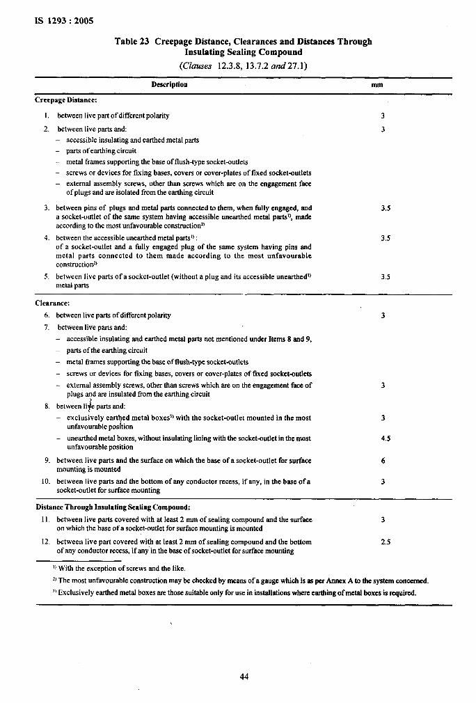
IS 1293:2005
Table 23 Creepage Distance, Clearances and Distances ThroughInsulating Sealing Compound
(Clauses 12.3.8, 13.7.2 and27.1)
Description mm
Creepage Distance
1.
2.
3.
4.
5.
between live part of different polarity
between live parts and:— accessible insulating and earthed metal parts
– parts of earthing circuit— metal frames supporting the base of flush-type socket-outlets— screws or devices for fixing bases, covers or cover-plates of fixed socket-outlets— external assembly screws, other than screws which are on the engagement face
of plugs and are isolated from the earthing circuit
between pins of plugs and metal parts connected to them, when filly engaged, anda socket-outlet of the same system having accessible unearthed metal parts!), madeaccording to the most unfavorable constmctionz)
between the accessible unearthed metal prntsl):of a socket-outlet and a fully engaged plug of the same system having pins andmetal parts connected to them made according to the most unfavorableconstruction2J
between live parts of a socket-outlet (without a plug and its accessible uneartbedl) 3.5metal parts
3
3
3.5
3.5
Clearance:
6. between live parts of different polarity 3
7. betweeo live parts and:— accessible insulating and earthed metal parts not mentioned under Items 8 and 9,
– parts of the earthing circuit. metal threes supporting the base of flush-type socket-outlets— screws or devices for fixing bases, covers or cover-plates of fixed socket-outlets
external assembly screws, other than screws which are on the engagement face of 3plugs and are insulated from the ewtbing circuit
&8. between Ii parts and:— exclusively eart~d metal boxes3)with the socket-outlet mounted in the most 3
unfavorable position— unearthed metal boxes, without insulating lining with the socket-outlet in the most 4.5
unfavorable position
9. between live parts and the surface on which the base of a socket-outlet for surface 6mounting is mounted
10. between live parts and the bottom of any conductor recess, if any, in the base of a 3socket-outlet for surface mounting
Distance Through Insulating Sealing Compound:
11, between live parts covered with at least 2 mm of sealing compound and the surface 3on which the base of a socket-outlet for surface mounting is mounted
12. between live part covered with at least 2 mm of sealing compound and the bottom 2.5of any conductor recess, if any”in the base of socket-outlet for surface mounting
u With tie exception of screws and the like.
z)The most unfavorable construction maybe checked by means of a gauge which is as per Annex A to the SYStCIII eoneemed.
3) Exclusively earthed metal boxes are those suitable only for use in installations where earthing of metal boxes is required.
44
27.2 Insulating sealing compound shall notprotrude above the edge of the cavity in which it iscontained.
27.3 Ordinary surface-type socket-outlets shall nothave bare current-carrying strips at the back.
Compliance with the requirements of 27.2 and 27.3 ischecked by inspection.
28 RESISTANCE OF INSULATING MATERIALTO ABNORMAL HEAT, TO FIRE AND TOTRACKING
28.1 Resistance to Abnormal Heat and to Fire
Parts of insulating material which might be exposed tothermal stresses due to electric effects, and thedeterioration of which might impair the safety of theaccessory, shall not be unduly affected by abnormalheat and by fire.
Compliance is checked by means of the tests asper 28.1.1 and, in addition, for plugs with pins providedwith insulating sleeves by the test of 28.1.2.
28.1.1 Glow-Wire Test
The test is performed according to IS 11000 (Part 2/Sec 1) under the following conditions:
— for parts of insulating material necessary to retaincurrent-carrying parts and parts of the earthingcircuit of fixed accessories in position, by the testmade at a temperature of 850”C.
I — for parts of insulating material, necessary to retaincurrent carrying parts and parts of the earthingcircuit of portable accessory in position, by thetest made at a temperature of 750”C.
— for parts of insulating material necessary to retaincurrent-carrying parts and parts of the earthing
I
I circuit in position, even though they are in contactwith them, by the test made at a temperature of650”C.
IIf the tests specified have to be made at more than1one place on the same specimen, care must be taken
Ito ensure that any deterioration caused by previoustests does not affect the result of the test to be
Imade.
Small parts, such as washers, are not subjected to testI of this sub-clause.
The tests are not made on parts of ceramic material.
NOTE — The glow-wire test is applied to ensure that an
~electrically heated test wire under defined test cortdltiortsdoesnot cause ignition of insulating parts or to ensore that a part ofinsulating material, which might be ignited by the heated testwire underdefinedconditions,isma limitedtimeto burrswithoutspswdkrg fire by flame or burningparts or dropletsfallingdownffom the tested part onto pinewood board coveredwith a tissuepaper.
IS 1293:2005
If possible, the specimen should be a completeaccessory.
NOTE— If thetestcannotbemadeon a completeaccessory,asuitable part may be cut from it for the purpose of the test.
The test is made on one specimen.
The test is made applying the glow-wire once.
In case of doubt, the test shall be repeated on twofimther specimens.
The specimen shall be positioned during the test inthe most unfavorable position of its intended use (withthe surface tested in a vertical position).
The tip of the glow-wire shall be applied to thespecified surface of the specimen taking into accountthe conditions of the intended use under which a heatedor glowing element may come into contact with thespecimen.
The specimen is regarded as having passed the glow-wire test it
— there is no visible flame and no sustained glowing,or if
— flames and glowing on the specimen extinguishwithin 30 s after the removal of the glow-wire.
There shall be no ignition of the tissue paper orscorching of the board.
28.1.2 The specimen of a plug with pins provided withinsulating sleeves is tested by means of the testapparatus as shown in Fig. 26.
This test apparatus consists of an insulating plate .4and of a metal part B: between these two parta an airspace of 3 mm shall be provided and this distance shallbe obtained through means which do not impair theair circulation around the pins.
The front surface of the insulating plate A shall beround and flat and have a diameter equal to twice themaximum permissible dimension of the engagementface of the plug. ,
The thickness of this insulating plate shall be 5 mm.
The metal part B shall be of brass and have, for thelength of at least 20 mm, the same shape as themaximum outline of the plug.
The rest of this metal part shall be so shaped thatthe accessory under test is heated through it byconduction, and that the heat transmission to theaccessory under test by convection or radiation isreduced to a minimum.
A thermocouple shall be inserted at a distance of 7mm from the front surface of the metal part in asymmetrical position, as shown in Fig. 26.
.
45
IS 1293:2005 ,,
The dimensions of the holes for the pins in the metalpart B shall be 0.1 mm larger than the maximumdimensions of the pins and the distances between pinsshall be the same as those given in Annex A; the depthof the holes shall be sufficient.
NOTE — The metal part B can be made of two or morecomponent pieces, for hole cleaning purposes.
The specimens are inserted in the test apparatus,placed in the most unfavorable horizontal position,when the test apparatus has reached a steadytemperature, measured by means of the thermocouple,of 120 + 5°C for accessories having a rated currentof 2.5 A or 180 + 5°C for accessories having a ratedcurrent of 6 A or 200 + 5°C for accessories having ahigher current ratings.
NOTE— The vatue of 200 * 5°C is provisional.
The temperature is maintained at those values for 3 h.
The specimens are then taken out tlom the test apparatusand are allowed to cool down to room temperature, atwhich they are maintained for at least 4 h.
The insulating sleeves of the pins of the samples arethen submitted to an impact test in accordance with 30but made at ambient temperature, and to a visualinspection.
NOTE — During vision the visual inspection, no cracks onthe insulating sIeeves shall be visible with the normal orcorrected vision without additional magnification, and thedimensions of the insulating sleeves shatl not be changert soas to impair the protection against accidental contact.
28.2 Resistance to Tracking
For accessories other than ordinary, parts of insulatingmaterial retaining live parts in position shall be ofmaterial resistant to tracking.
Without drying, but after shaking off any drops,the parts are placed for 10 min in a box containingair saturated with moisture at a temperature of27+ 5°C.
After the parts have been dried for 10 min in a heatingcabinet at a temperature of 100 A 5“C, their surfacesshall show no signs of rust.
NOTES
1 Traces of rust on sharp edges and any yellowish filmremovable by rubbhg arc ignored.
2 For small springs and the like, and for inaccessible partaexposed to abrasion, a layer of grease may provide sufficientprotection against rusting. Such parts are only subjected tothe test if there is doubt about the effectiveness of the greasefilm, and the test is then made without previous removal ofthe grease.
30 ADDITIONAL TESTS ON PINS PROVIDEDWITH INSULATING SLEEVES
The material of the pin-insulting sleeves shall beresistant to the stresses to which it may be subjectedat the high temperature likely to occur in conditionsapproaching the bad connection conditions and at lowtemperatures in particular conditions of service.
Compliance is checked by means of the following tests.
30.1 Pressure Test at High Temperature
The specimens are tested by means of the apparatusas shown in Fig. 29. This apparatus has a rectangularblade (see Fig. 29) with an edge 0.7 mm wide, to beused in the case of round pins, or a blade having around shape (see Fig. 29), with a dkmeter of 6 mmand art edge of 0.7 mm, in other cases.
The specimens are placed in position as shown inFig. 29,
Compliance is checked according to IS 2824. The force applied through the blade is 2.5 N.
Ceramics parts are not tested. The apparatus, with the specimen in position, is
The material under test shall pass a tracking index ofmaintained for 2 h in a heating cabinet at a temperature
175 V using test solution A with the interv d betweenof 200 ● 5“C.
drops 30s +-5s. No flash over or breakdow n between The specimen is then removed from the apparatus and,electrodes shall occur before a total of 50 drops has within 10s, cooled by immersion in cold water.fallen.
The thickness of the insulation is measured29 RESISTANCE TO RUSTING immediately at the point of impression.
Ferrous parts, including covers and surface mountingboxes shall be adequately protected against rusting.
Compliance is checked by the following test.
All grease is removed from the parts to be tested, byimmersion in carbon tetrachloride, trichloroethane oran equivalent decreasing agent, for 10 min.
The parts are then immersed for 10 min in a 10 percentsolution of ammonium chloride in water at atemperature of 27 + 5“C.
The thickness, within the area of the impression shallbe not less than 50 percent of the thickness measuredbefore the test.
NOTE —The vrdues2.5 N anu 200 * 5°C are provisional.
30.2 Static Damp Heat Test
A set of three specimen is submitted to twodamp heat cycles in accordance with IS 9000 (Part 5/Sec 1 and 2).
After this treatment and atler recovery to ambient
46
?-
IS 1293:2005
temperature, the specimens are submitted to thefollowing tests:
— insulation resistance and electric strength test inaccordance with 17; and
— abrasion test, in accordance with 24.7.
30.3 Impact Test at Low Temperature
The specimens are subjected to an impact test bymeans of the apparatus as shown in Fig. 30. The massof the falling weight is 100 + 1 g.
The apparatus, on a sponge rubber pad, 40 mm thick,is placed, together with the specimens, in a retl-igeratorat a temperature of – 15 + 2°C for at least 24 h.
At the end of this period, each specimen, in turn, isplaced in position, as shown in Fig. 30, and the fallingweight is allowed to fall from a height of 100 mm.Four impacts are applied successively to the samespecimen, rotating it through 90° between impacts.
NOTES
1 After the test, the specimens are allowed to attainapproximatelyroom temperature and are then examined.
2 No cracks of the insulating sleeves shall be visible with thenorrnrdor corrected vision without additional magnification.
3 The cooling period of 24 h mentioned in the tests of 30.3and 30.4 includes the time necessaryfor cooling down theapparatus.
30.4 Tests at Low Temperature
A set of three specimens is maintained at–15° + 2°Cfor 24 h. After recovering to ambient temperature, thespecimens are submitted to the following tests:
— insulation resistance and electric strength test, inaccordance with 17.
— abrasion test, in accordance with 24.7.
31 TESTS
31.1 Type Test
The following shall be carried out as type tests onselected samples (see 5) of accessories drawnpreferably at random from a regular lot of productionfor criteria of acceptance (see 5).
1) Rating (see 6);
2) Classification (see 7);
3) Marking ( see 8);
4) Checking of dimensions (see 9);
5) Protection against electric shock (see 10);
6) Provision for earthing (see 11);
7) Terminals (see 12);
8) Constructional requirements of fixed socketoutlets (see 13);
10)
11)
12)
13)
14)
15)
16)
17)
18)
19)
20)
21)
22)
23)
24)
25)
9) Construction of plugs and portable socketoutlets (see 14);
Interlocked socket-outlet (see 15);
Resistance to ageing, to harmti.d ingress of waterand to humidity (see 16);
Insulation resistance and electric strength(see 17);
Operation of earthing contacts (see 18);
Temperature-rise (see 19);
Making and breaking capacity (see 20);
Normal operation (see 21);
1
al,,
Force necessary to withdraw the plug (see 22); f,,
Flexible cables and their connection (see ,23);.,..::
Mechanical strength (see 24);,;!.i:’
Resistance to heat (see 25);!.
Screws, current carrying parts and connections ‘~(see 26); !,
j’Creepage distances, clearances and distancethrough sealing compound (see 27); ~’;
Resistance of insulation material to abnormalheat, to fwe and to tracking (see 28);
Resistance to rusting (see 29); and
Additional tests on pins provided with insulating.,
sleeves (see 30).
31.1.1 The specimen subjected to type tests shall pass ithe tests for providing conformity with the requirementsof this standard.
31.2 Acceptance Tests)
The following shall constitute acceptance test:
a)
b)
c)
d)
e)
f)
Marking (see 8); ,
Resistance to ageing, to harmtld ingress of waterand to humidity (see 16); 9
Insulation resistance and electric strength(see 17);
Temperature-rise (see 19); ;’
Making and breaking capacity (see 20); and
Mechanical strength (see 24);
31.2.1 A recommended sampling procedure for~!I
acceptance test is specified in Annex C.
31.3 Routine Tests
The following shall constitute routine tests:
a) Marking (see 8); and
b) Electric strength (Flash test) (see 17.3).
47
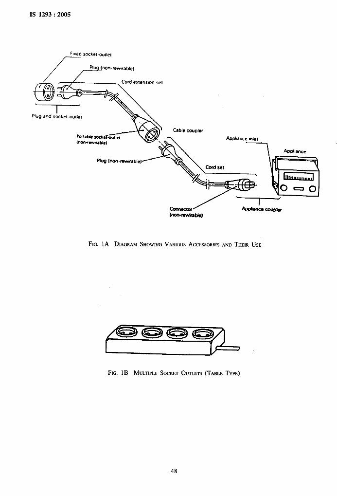
IS 1293:2005
Fl~ed socket.ouliel
/
/ /J-On-’ew’’ae’e’
&l:‘ Cord emenslon set9
-—.
&
“‘b
%plug andsockel outlet
..
~a~c SOcketmtletlnofwawirable)
.ug,.>~~ JInl
FIG. 1A DIAGRAMSHOWINGVARIOUSACCESSORIESANDTHEIRUSE
FIG. lB MULTIPLE SOCKETOUTLETS(TABLE TYPE)
48
..
$.,, .*’‘.*
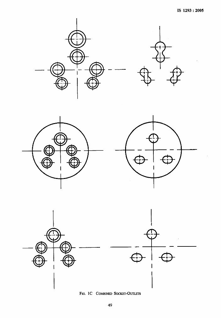
IS 1293:2005
&T
@-
-* $l–-. +
——
I
e-—— —
e-t
%
FIG. lC COMBINEDSOCKET-O~S
49
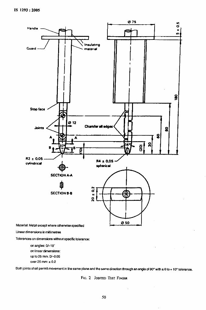
IS 1293:2005
,.. .
m,,.,,.’,‘r!
Guard -7
/
t
I
III
t-075
1m-.
—. ,.
012nChornfora50@oe ,
-.A
f72 ~0.05
qlindricaf
+SECTION A-A
SECTION B-E
R4 k 0.05 ~ephericaf ,
Material: Metal except where otherwise specified ~
Linear dimensions in millimetres
Tolerances on dimensions without specific tolerance:
on angles: 0/-10’
on linear dimensions:
up to 25 mm: 0/-0.05
over 25 mm:* 0.2
..
s, ..*A
I
Both joints shall permit movement in the same plane and the same direction through an angle of 90° with a Oto + 10° toleranoe.
FIG. 2 JOINTEDTESTFINGSR
50
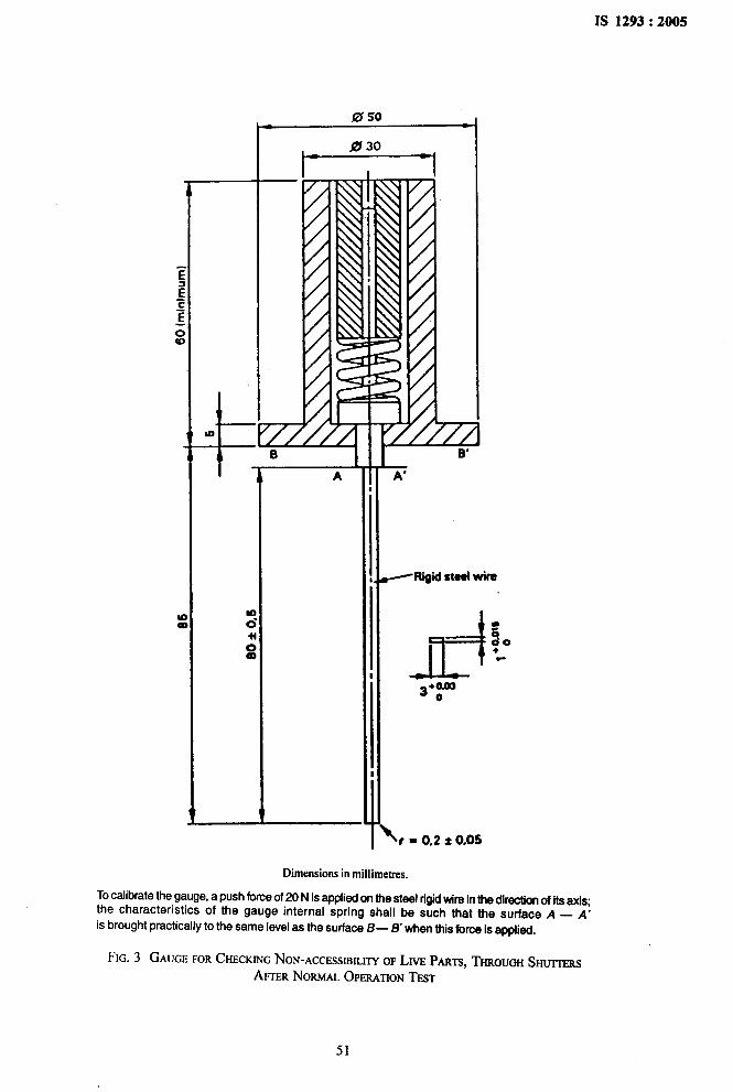
IS 1293:2005
050● 9
t-030
-iI
A
I
B—A’
I
s
‘x’
<RifJii ataal Wira
Jd+OmJ30 .
<,* 0,2 * (),05
Dimensionsin millimetres.
To calibrate the gauge, a push force of 20 N is applied on the steel rigidWe in the direction of its axis;the characteristics of the gauge internal spring shall be such that the surface A — A’
is brought practically to the same level as the surface B — B’ when this forca is appli~.
FIG.3 GAUGEFORCHECKINGNON-ACCESSIBILITYOFLIVEPARTS,THROUGHSmrrERS
AFTERNORMALOPERATIONTEST
51
‘,b
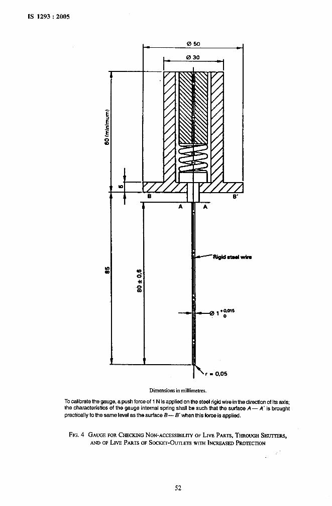
.,IS 1293:2005
050a 9
i-030
4I
L
A
To calibrate the gauge, a push force of 1 N is a~plied on the steel riaid wire in the direction of its axis:the characteris~cs of the gauge internal spring shall be such th~t the surface A — A’ is brought
practically to the same level as the surface B— H when this force is applied.
FIG.4 GAUGEFORCHECKINGNON-ACCESSIRLLITYOFLm PARTS,THROUGHSmrrnms,ANDOFLm PARTSOFSOCKET-OUTLETSWITHINCREASEDPROmCTION
‘1
52

IS 1293:2005
10s[ rod (metal)
I I
m0.00●
u)
Q
-i
t
Riiht-angled sharp. edges
FIG. 5 GAUGEFORVERIFICATIONOFGROOVES,HoLEs ANDREVERSETAPERS
I
m.P— —--- o
.—. . -H-— —--- In
~—-—-.~- —-- — .-—-— .
L- ——-.
~-—-—. t+~-—-- —
L-———
‘c’ ‘142 ~ 0.5 I
Dimensions in millimetres.
NOTES
1 The dimensions a and b tue to be chosen according to the ~ppropriate dimension given in Amwx A.
2 Dimensions and arrangement of pins complying with Annex A.
FIG. 6 DEVICEFORCHECKINGTHERESISTANCETOLATERALSmMN
53
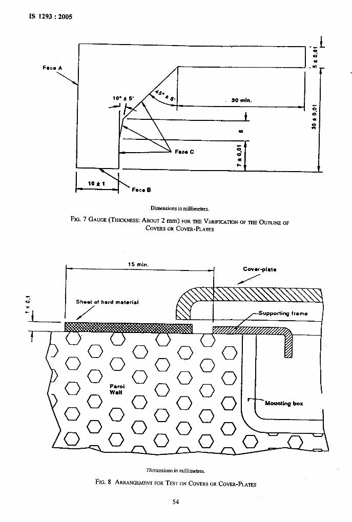
IS 1293:2005
r---
.’,
,.:
Face A
\
10”: 5“ SO min.
t
-- L00“
0
0*
=b10$1FacIBB
Dimensionsin miliimet.res.
FIG. 7 GAUGE(THICKNESS:ABOUT2 mm) FORmm VERIFICATIONOFmm Oumrm OF
COVERSORCOVER-PLATES
15 mincover*ial@
I
>upporliwg frnme
E T1- Mounting box
I
I
j’..
Dimensions in mi]iimetres.
FIG. 8 ARRANGEMENTFORTESTONCOVERSORCOVER-PLATES
54
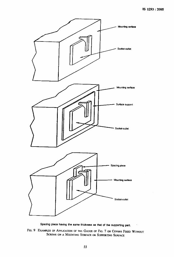
IS 1293:2005,,,‘.,
Mountingsurfsce
Socket-outlet
Mountingsurface
Surfacesupport
.,
Socket-outlet
Spacing piace having the same thickness as that of the suppcding part.
FIG. 9 Ex.mms OFAPPLICATIONOF m GAUGEOFFIG. 7 ON Covms FIXEDWrmou-r
Screws ONA MOUNTINGSURFACEOR SUPPORTINGSURFACE
I
,:
.
55
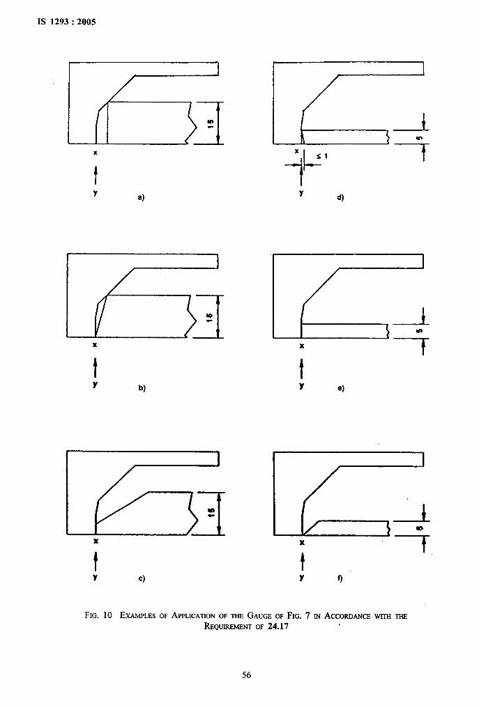
IS 1293:2005
r- .-
Bmf.,’, ,,
,!
1
Hm
x
t
Y a)
x
Y c)
Lx
11-SI
Y d)
Y e)
Y f)
i
.
FIG. 10 EXAMPLESOF APPLICATIONOF THEGAUGEOF FIG. 7 IN ACCORDANCEWITHTHEREQUREMINT OF 24.17
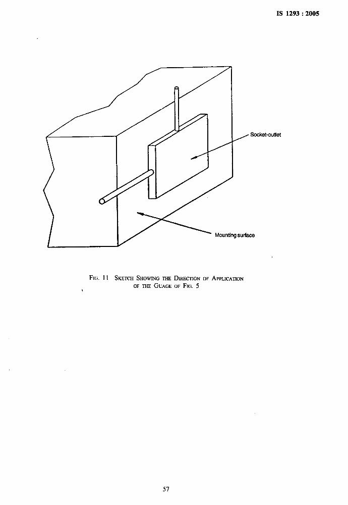
.
1S 1293:2005
..,,“
Socket-outlet/
FIG. 11 SKETCHSHOWINGTHEDIRECTIONOF APPLICATIONOF THEGUAGEOF FIG. 5
,,
57
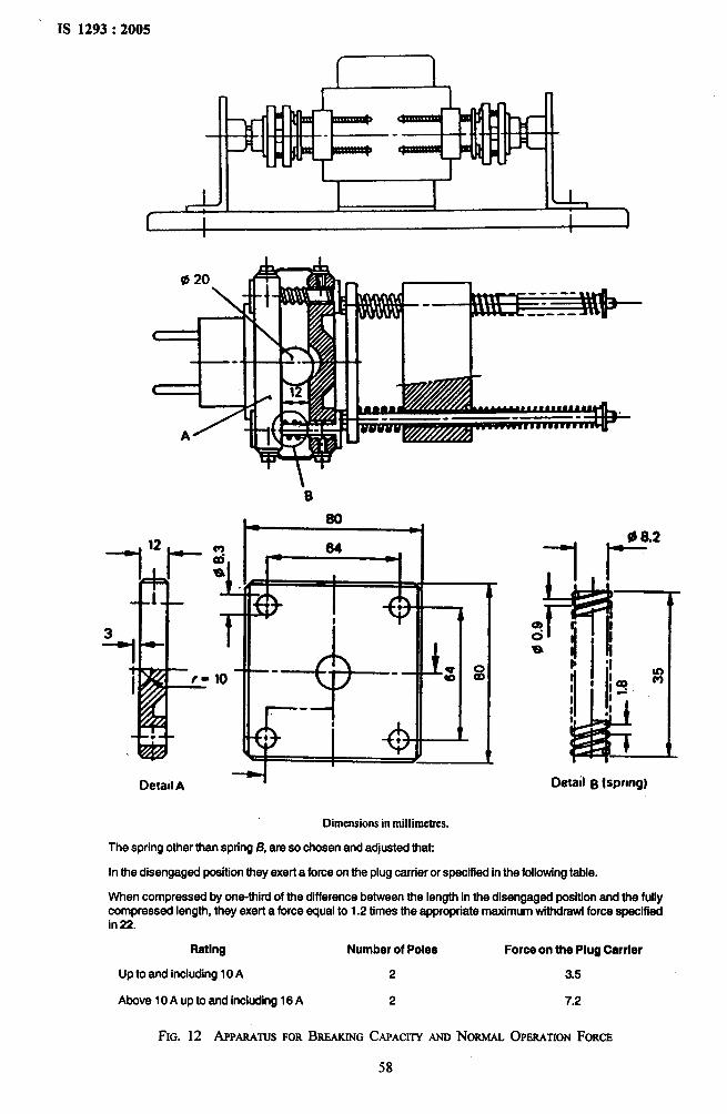
1S 1293:2005
1 ,*
‘B
DetadA
Dimensionsin millimetres.
-1 ?2
Detail B lspnng)
The spring other than spring B, are so chosen and adjusted that
In the disengaged position they exert a force on the plug carrier or specified in the following table.
When compressed by one-third of the difference between the length in the disengaged position and the fullycompressed length, they exert a force equal to 1.2 times the appropriate maximum withdrawi force specifiedin 22.
Rating Number of Poles Force on the Plug Carrier
Up to and including 10 A 2 3.5
Above 10A up to and including 16 A 2 7.2
FIG. 12 APPARATUSFORBREAKINGCAPACITYANDNORMALOPERATIONFORCE
58
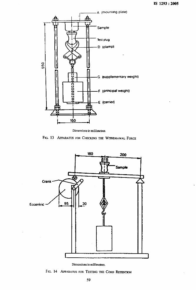
IS 1293:2005
A pmountmgplale)
cuIi
entaw wmght]
I weight)
h 150 J
Dimensions in millimetres.
FIG. 13 APPARATUSFORCHECKINGTHEWITHDRAWALFORCE
xCrenk
Eccentric 95
c-
[30
; !:.
I
.
“i
Dimensions in millimetres.
FIG. 14 APPARATUSFORTESTtNGm CORD RETENTION
59
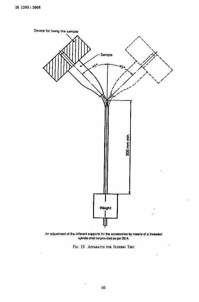
IS 1293:2005
D-e for fixing the sample
An adjustment of the different supports for the accessories by means of a threaded
spindle shall be provided as per 23.4.
.
FIG. 15 APP,mwws FORFLEXINGTEST
60
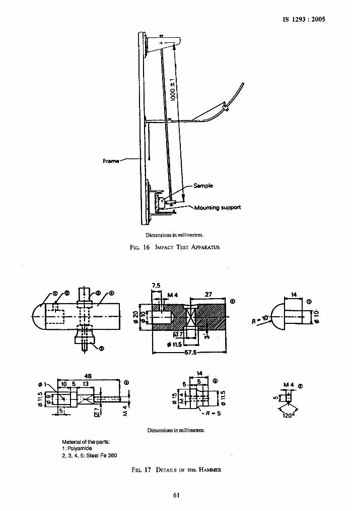
01
a
Dimensions in millimetres.
FIG. 16 IMPACTTESTAPPmmJs
Material of the parta:1: Polyamide
2, 3, 4,5: Steel Fe 360
7.5
z ‘~R-5
Dimensions in millimetres.
IS 1293:2005
.’,
,-,,.
.
FIG. 17 DETJUMOFTHEHAMMER
61
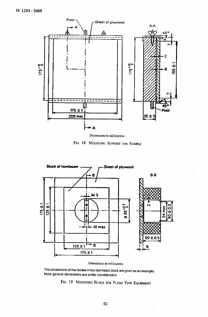
v-
bl:...’,
,.IS 1293:2005
Pwol\ rSheet of pIyWKKW
A-A
A------ ------ ~--- ----- ---I
i!I
.
I II
ii.—- s
1Oc
Twf=
II
------- ---T ------- ---
u175*1;
a
*
l--A
Dimensions in miilimetres.
FIG. 18 MOUNTINGSUPPORTFORSAMPLE
6“d~7 rsheetofplywQod
B-B
.
&M3
. .—
* 1
,
--i--@175 * 1
Dimensions in millimetres.
The dimensions of the recess in the hornbeam block are given as an examole.!“
More general dimensions are under consideration. -!.
FIG. 19 MOUNTINGBLOCKFORFLUSHTYPEEQUIPMENT
62
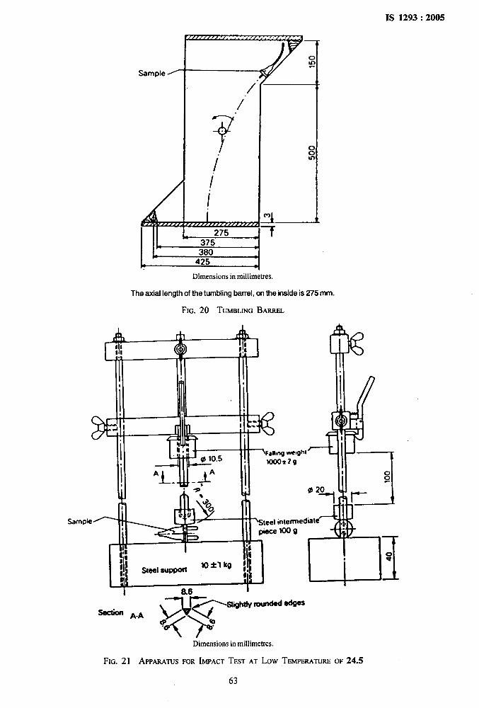
,,.,,IS 1293:2005
Sample ~
/
/
I/
I&The axial length of the tumbling barrel, on the inside is 275 mm.
FIG. 20 TUMBLINGBARREL
; >
A h
~ I1
1 b:ll -Fan” “-al 10.5 .,
Afo1
IIIj -1I g1
I
Al~-.-i..Ill
I‘1I L- Ii!-+ Ill Ill ‘1
-i!t4!P
FIG. 21 APPARATUSFORIMPACTTESTAT Low TEMPERATUREOF 24.5
63
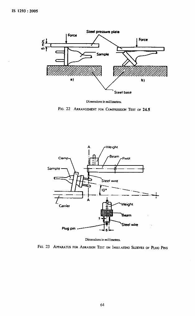
IS 1293:2005
,.
/?
Steel psessura plateI Force
a) ‘v’“Sleel base
Dimensions in millimetres.
FIG. 22 ARRANGEMENTFORCOMPRESSIONTEST
b)
OF 24.5
A
f
VVwght
I1
Clamp
Sample
f.—. — —.. —
t!A
1
Carrier
Steel wirePlug pin
Dimensions in mil]ime~s.
FIG. 23 APP,wmn FORABRASIONTESTON INSULATINGSLEEVESOF PLUGPms
$‘, ,.*‘@
64
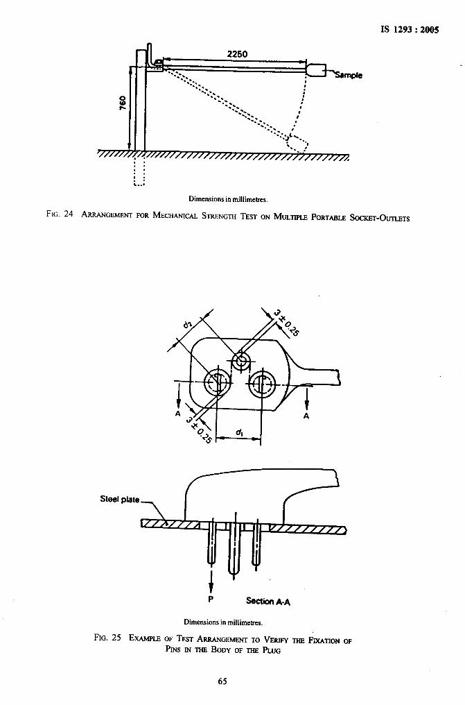
IS 1293:2005
@e-. :...... .
‘.’. .. :.-‘ Q-:*
.:. f’.-. ...-. .’-.:.
. .. . L’..) %..
“. 0
~~f//////,,,,,,-.. . ..’
. ///////////////// /fi,.. .. .,.. .%-.,
Dimensionsin millimetres.
FIG. 24 ARRANGEMENTFORMECHANICALSTRENGTHTESTON MULTIPLEPORTAB~ SOCKET-OUTLETS
Steel pbte
i r ‘. v//////,#j
o I I
4 4● .
+ “P s%ctii A-A
Dimensionsin miilimetres.
FIG. 25 EXAMPLEOF TESTARRANGEMENTTO VERIFYTHEFiXMTONOF
PINSIN THEBODY OF m PLUG
65
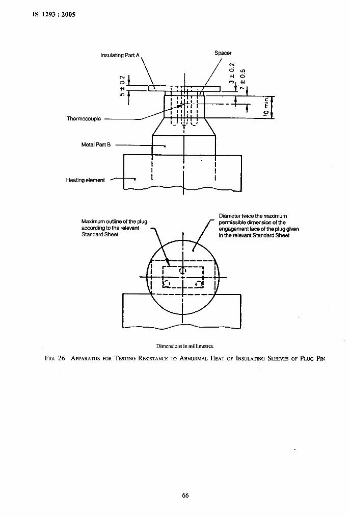
IS 1293:2005
.
k,,..’:
,“.,
Insulating Part A
\N
oUu-)
Thermocouple
b $
Metal Part B ●
I I I
I
Heating element / v I :
Diameter twice the maximum
WIo++
permissible dimensicm of theengagement face of the plug givenin the relevant Standard Sheet
Maximum outline of the plugaccording to the relevantStandard Sheet
1-
Dimensions in millimetres.
FIG. 26 APPWmS FORTESTINGRESISTANCETO ABNORMALI-WT OF INSULATINGSLEEVESOF PLUGPm
66
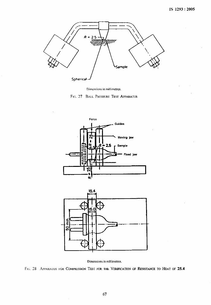
IS 1293:2005
Spherical J
Dimensions in millimetres.
FIG. 27 BALL PRESSURETESTAPPMLATUS
Force
. I ~ ‘Uidee
I
m-.Moving jaw
.f?=2S ~ Sample
j- .—.
~
Fixed jaw
3..
>
—.— —.— --
3-.
Dimensions in millimetres.
‘1
,.
“i
Fi~. 28 AWARATUSFORCOMPRESSIONTESTFORTHEVERIFICATIONOF RESISTANCETO HEAT OF 25.4
67

IS 1293:2005.,
.,,,
1 I
A Front view B Front view
r. emm
0.7 mm------- .
I t J
‘SucrflaSpecimen
P
FIG. 29 APPARATUSFORPRESSURETESTAT HIGH TEMPERATURE
Faltingwright100*1
Speclmterm100 g
SecoonA”A
~lVr~Sl%htbm.ndededgeS
‘d0
%*
‘1
.“
Dimensions in millimetres.
FIG. 30 IMPACTTESTAPPARAm_JSON PINSPROVmEDWITHINSULATINGSLEEVES
68
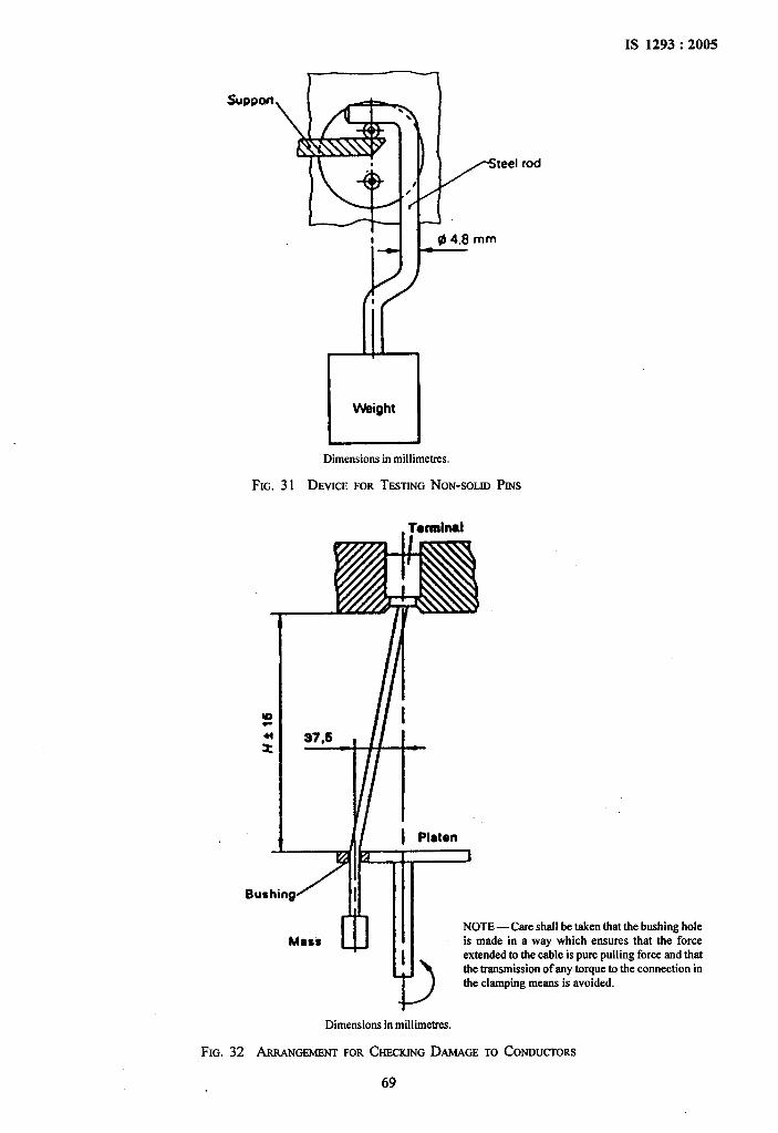
IS 1293:2005
...,,,, !
Sumwt
[eel
Dimensions in millimetres.
FIG. 31 DEVICEFORTESTINGNON-SOLIOPINS
rod
Bu
vDimensions in millimebes.
FIG. 32 ARMNGEMENTFORCHECRINGD.MAGE
69
TO CONDUCTORS
.,
+,;,..$,.44
‘1
>
i
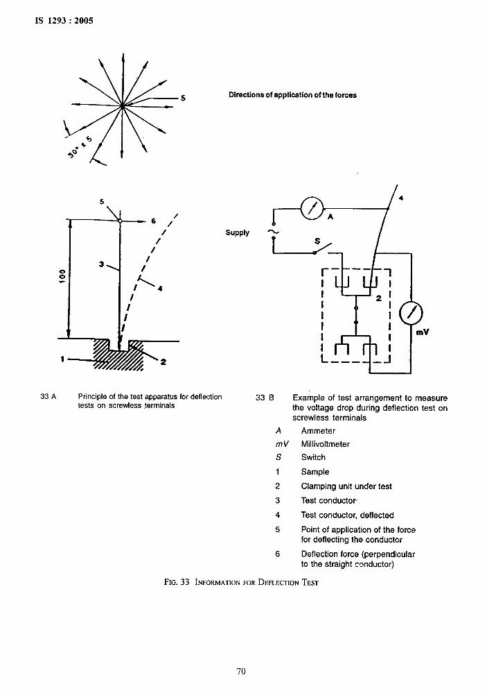
IS 1293:2005
5 Directions of application of the forces
. *$
~o”
supply
33 A Principle of the test apparatus for deflection 33 B Example of test arrangement to measuretests on screwless terminals the voltage drop during deflection test on
screwless terminals
A Ammeter
mV Millivoltmeter
s Switch
1 Sample
2 Clamping unit under test
3 Test conductor
4 Test conductor, deflected
5 Point of application of the force
for deflecting the conductor
6 Deflection force (perpendicularto the straight mnductor)
:,b
s, ,’,..*
‘@
.
FIG. 33 INFORMATIONFORDEFLECTIONTEST
70
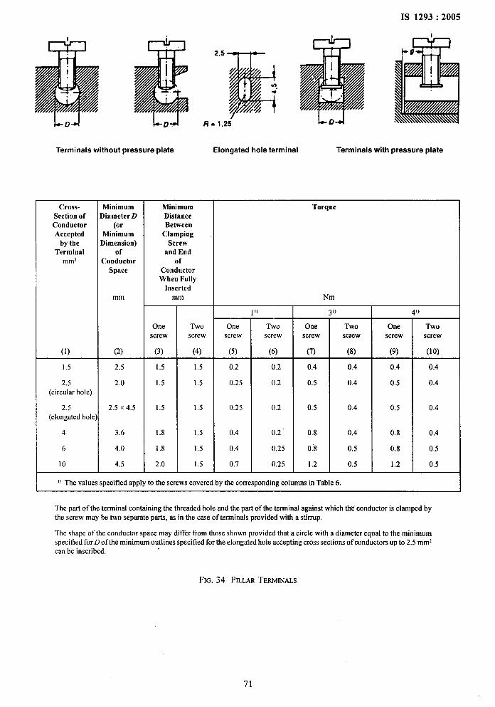
IS 1293:2005
2,5
Ir- UI 1
*
LD+I L- D-A
Terminals without pressure plate Elongated hole terminal Terminals with pressure plate
MinimumDistanceBetween
ClampingScrew
and Endof
ConductorWhen Fully
Insertedmm
Cross-Section ofConductorAccepted
by theTerminal
mm2
Minimum)iametcr D
(orMhrimumlimcnsion)
ofConductor
Space
mm
(2)
2.5
2.0
2.5 X4.5
3.6
4.0
4,5
Torque
Nm
)
Twoscrew
(6)
0.2
0.2
0.2
0.2
0.25
0.25
)
Twoscrew
(8)
0.4
0.4
0.4
0.4
0.5
0.5
1)
Onescrew
(3)
1.5
1.5
1.5
1.8
1.8
2.0
Twoscrew
(4)
1.5
1.5
1.5
1.5
1.5
1.5
Onescrew
(5)
0,2
0.25
0.25
0.4
0.4
0.7
Onescrew
(7)
Onescrew
(9)
Twoscrew
(lo)(1)
1.5
2.5(circular hole)
2.5(elongated hole
4
6
10
0.4
0.5
0.5
0.8
0.8
1.2
0.4
0.5
0.5
0.8
0.8
1.2
0.4
0.4
0.4
0.4
0.5
0.5
‘1
.
0 Thcv~ues specified apply totiescrews covcrcd bytiecomcsponding columns in Table6
The part of the terminal containing the threaded hole and the part of the terminal against which tie conductor is clamped bythe screw may be two separate parts, as in the case of terminals provided with a stirrup.
The shape of the conductor space may differ from those shown provided that a circle with a diameter equal to the minimumspeciticd for D of the minimum outlines specified for the elongated hole accepting cross sections of conductors upto 2.5 mmzcan be inscribed.
FIG. 34 Pm,m TERMINALS
71
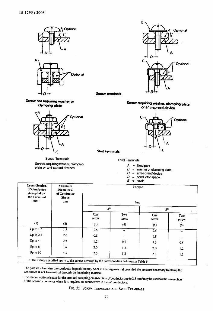
IS 1293:2005
.
i.’,
sot-d
A
Opmnftl
d-D&
optional
Screw Terminals
Screws requiring washer, clampingplate or anti-spread devices
Stud lermmals
B
%
A
Optional11
A
Screw nsquiring weeher. damping pbteor anti-x ~
Stud Terminals
coptional
A = fixed partB = washer or clamping plateC = anti-spread deviceD = conductor spaceE = Sturi=— -----
Cross -Section Minimum Torqueof Conductor Diameter DAccepted by of Conductorthe Terminal Shape
~mz mm Nm
31) 30
One Two One Twoscrew screw Scrxw screw
(1) (2) (3) (4) (5) (6)up to 1.5 1.7 0.5 0.5Up to 2.5 2.0 0.8 0.8up to 4 2.7 1.2 0.5 1.2 0.5Up to 6 3.6 2.0 1.2 2.0 1.2up to 10 4.3 2.0 1.2 ?0 1.2
0 The values specified apply to the screws covered by the corresponding columns in Table 6.
The part which retains the conductor in position maybe of insulating material provided the pressure necessary to clamp theconductor is not transmitted through the insulating material.
The seeond optional space for the terminal accepting cross-sectionof conductorsup to 2.5 mmzmaybe used for the connectionof the second conductor when it is required to connect two 2.5 mmz conductors.
I
FIG. 35 SCREWTERMINALSANDSTUDTERMINALS
72
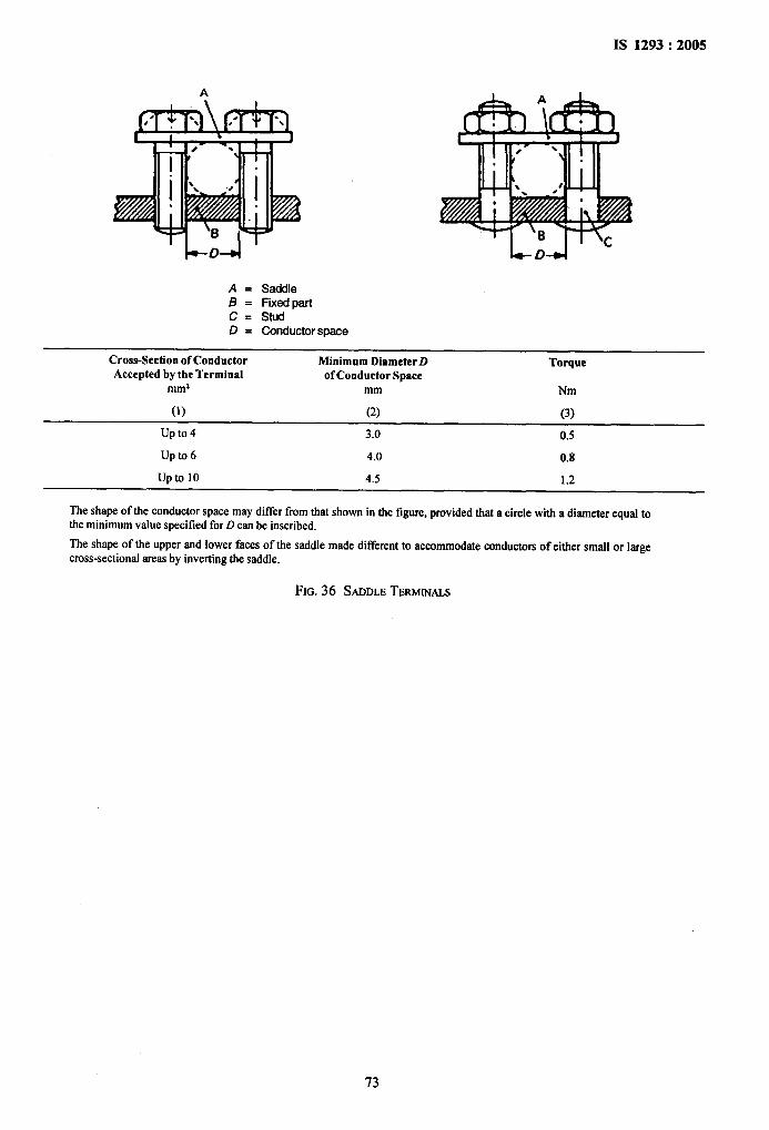
A
+D4
A = SaddleB = Fixad partC = StudD = Conductor space
Cross-Section of Conductor Minimum DiameterD TorqueAccepted by tbe Terminal of Conductor Space
~mz mm Nm
(1) (2) (3)
up to 4 3.0 0.5
Up to 6 4.0 0.8
up to 10 4.5 1.2
Theshapeof theconductorspacemaydifferfromthat shown in the figure, provided that a circle with a disrneter equal tothe minimum vahse specified for D can be inscribed.
The shape of the upper end lower faces of the saddle made different to accommodate conductors of either small or largecross-sectional areas by inverting the saddle.
,.,
FIG.36 SADDLETERMINALS
.
73
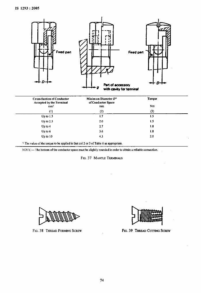
1S 1293: 2005
ixed pal rl
Cross-Section of Conductor Minimum DiameterD]) TorqueAccepted by tbe Terminal of Conductor Space
~m2 mm Nm
(1) (2) (3)
up to 1.5 1.7 1.5
Up to 2.5 2.0 1.5
up to 4 2.7 1.8
UP to 6 3.6 1.8
up to 10 4.3 2.0
u The value of thetorque to be applied is that COI2 or 3 of Table 6 as appropriate.
NOTE — The bottom of the conductor space must be slightly rounded in order to obtain a reliable connection.
FIG. 37 MA~E TERMINALS
FIG. 38 THREADFORMINGSCREW FIG. 39 THREADCroci SCREW
.,
.
74
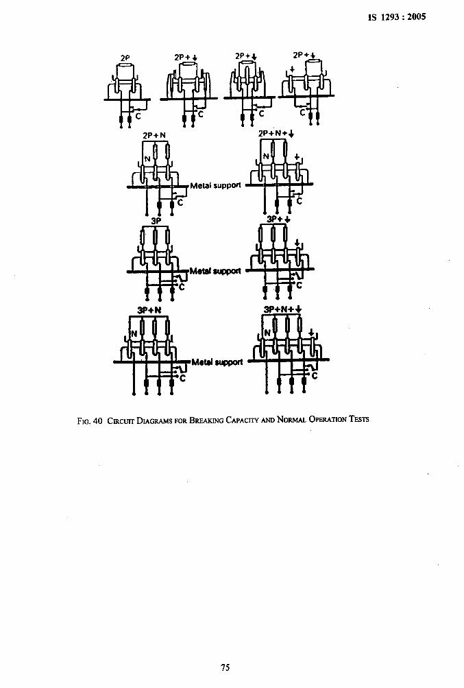
.,.
1!’+3P
y“eta’s”ppm“7T3P+ ,
* !!$4
Metal StJPPOII
c c
3P+N 3P+ N++
Metal supfmt
●
IS 1293:2005
‘1
FIG.40 CIRCUITDIAGRAMSFORBREAKINGCAPAC~- NOHOPEWmON TESTS
.
75
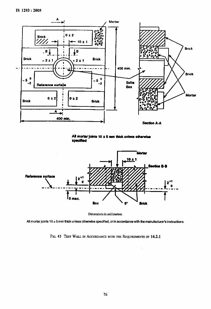
IS 1293:2005
.
,1.’,
.,
J+
Brick
------ ----- .- .-.-,. ---
- 5-;f%fomnoe surfa&
*
400 mfn.
Mortar—
-
400 min.
I I
LSalon A-A
Allmoftujdnt9 10* S mm thick unless othofwbSpodlied -
Rofolmco Sudaco
\
+1o-------- ----
Box >6. -~
Dimensions in millimetres.
All mortar joints 10 t 5 mm thick unlaas otherwise specifiad, or in accordance with the manufacturer’s instructions.
FIG. 41 TESTWti m ACCORDANCEwrm mm REQUIRSMBWS OF16.2.1
; t.:
I
.
. “$
76
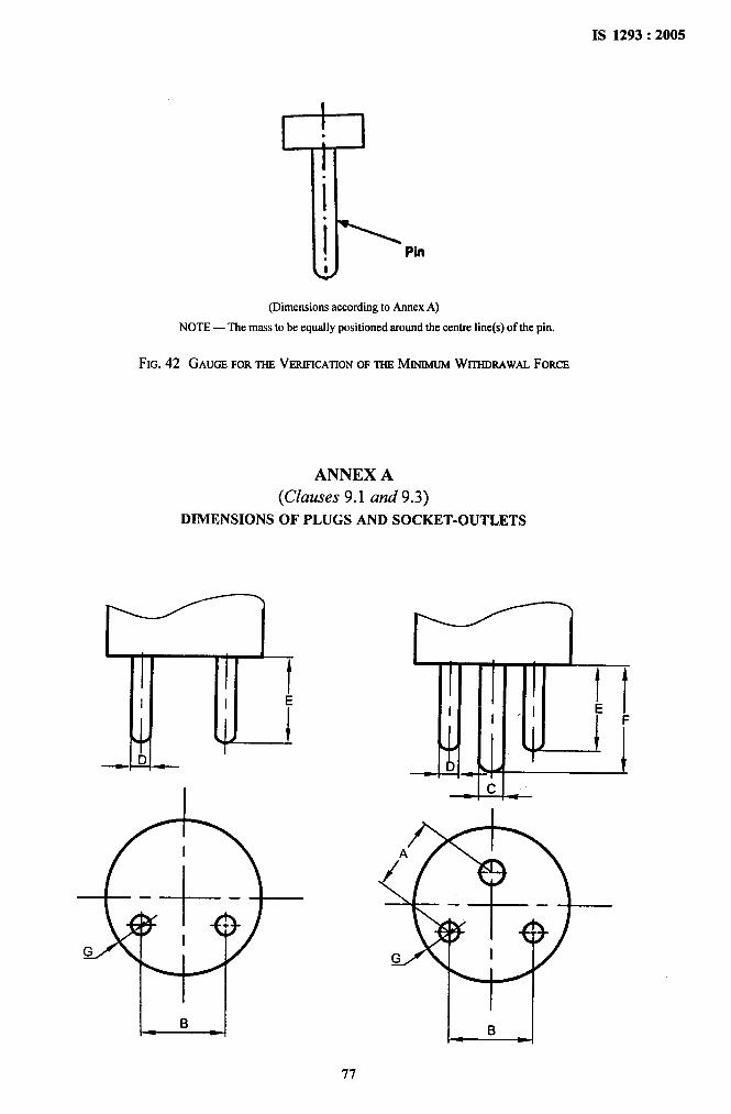
IS 1293:2005
...
,,, I
,, !,
T’..I.1 Pin.t
(Dimensions according to Annex A)
NOTE— The mass to be equally positioned around the cartre line(s) of the pin.
FIG. 42 GAUGEFORTHEVERIFICATIONOFTHEMINIMUMWITHDRAWALFORCE
ANNEX A
(Clauses 9.1 and 9.3)
DIMENSIONS OF PLUGS AND SOCKET-OUTLETS
--k-L-
..
+‘*,,. ,‘~
‘1
.
77
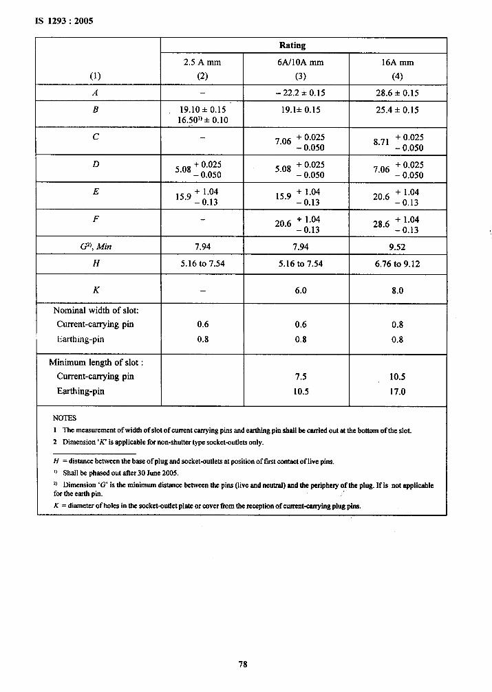
Rating
2.5 A mm 6A/10A mm 16A mm
(1) (2) (3) (4)
A — –22.2 + 0.15 28.6 + 0.15
B 19.10+0.15 19.1+ 0.15 25.4 + 0.1516.501) + 0.10
c — ~ 06 + 0.0258.71
+ 0.025– 0.050 – 0.050
D + 0.025 s 08 + 0.025 + 0.0255“08 – 0.050 – 0.050
7.06– 0.050
E + 1.04 159 + 1.04 + 1.0415”9–0.13 – 0.13
20.6–0.13
F 206 + 1.04 286 + 1.04– 0.13 – 0.13
@), Mi~ 7.94 7.94 9.52
H 5.16 to 7.54 5.16 to 7.54 6.76 to 9.12
K — 6.0 8.0
Nominal width of slot:
Current-carrying pin 0.6 0.6 0.8
Earthing-pin 0.8 0.8 0.8
Minimum length of slot :
Current-carrying pin 7.5 10.5
Earthing-pin 10.5 17.0
NOTES
1 The measurementof width of slot of current carrying pins and eartldng pin shall be carried out at the bottom of the slot.
2 Dimension‘K’ isapplicablefor non-shutter type socket-outlets only.
H = distance between the base of plug and socket-outlets at position of first contact of live pins.
u Shall be phased out @r 30 June2005.
Z) Dimension ‘G’ is the minimum dlstrmcebetweenthe pins (live and nerrtrtd)andthePeriphev of the plug. If k not applicablefor the earth pin.
K = diameter of holes in the socket-outlet plate or cover tkrm the reception of current-carrying plug pins.
,’
i
78
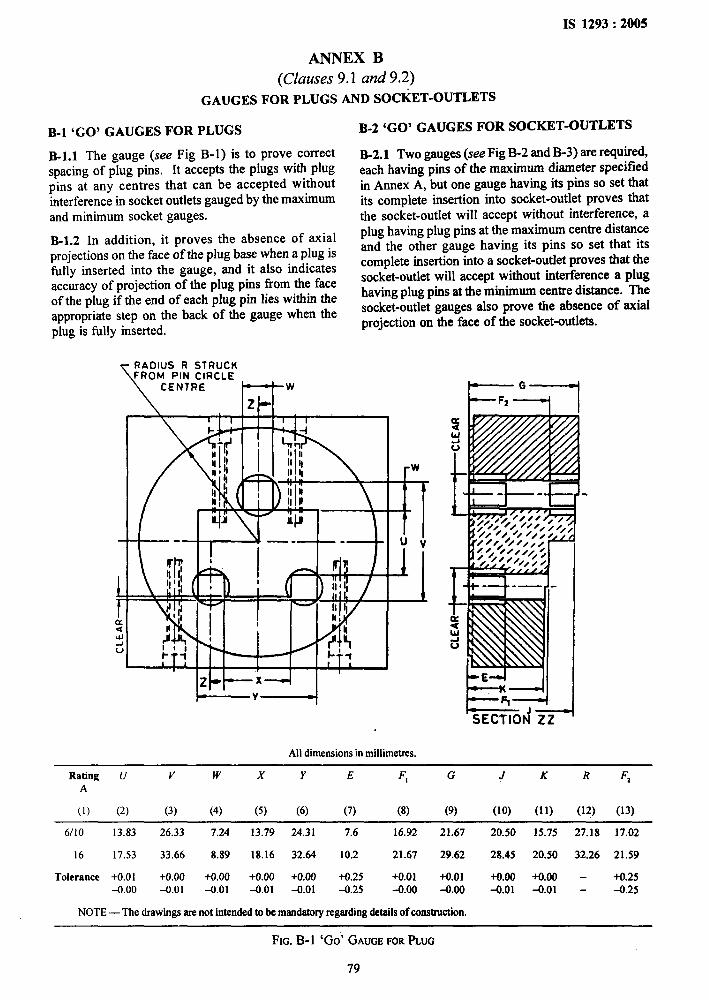
IS 1293:2005
m!, .
.’,
ANNEX B
(Clauses 9.1 and 9.2)
GAUGES FOR PLUGS AND SOCtiT-OUTLETS
B-1 ‘GO’ GAUGES FOR PLUGS
B-1.l The gauge (see Fig B-1) is to prove correctspacing of plug pins. It accepts the plugs with plug
pins at any centres that can be accepted withoutinterference in socket outlets gauged by the maximumand minimum socket gauges.
B-1.2 In addition, it proves the absence of axialprojections on the face of the plug base when a plug isfitly inserted into the gauge, and it also indicatesaccuracy of projection of the plug pins from the faceof the plug if the end of each plug pin lies within theappropriate step on the back of the gauge when theplug is filly inserted.
Y:i;Fmw
B-2 ‘GO’ GAUGES FOR SOCKET-OUTLETS
B-2.1 Two gauges (see Fig B-2 and B-3) are required,each having pins of the maximum diameter specifiedin Annex A, but one gauge having its pins so set thatits complete insertion into socket-outlet proves thatthe socket-outlet will accept without interference, a
plug having plug pins at the maximum centre distanceand the other gauge having its pins so set that itscomplete insertion into a socket-outIet proves that thesocket-outlet will accept without interference a plughaving plug pins at the minimum centre distance. Thesocket-outlet gauges also prove the absence of axialprojection on the face of the socket-outlets.
H--’+ I
Alldimensions inmillimetres.
I=el
,,
!
,$:,
/>’
1
?5ECT;Ori %_
Rating U v w x Y E F, G J K R F,A
(1) (2) (3) (4) (5) (6) (7) (8) (9) (lo) (11) (12) (13)
6/10 13.83 26.33 7.24 13.79 24.31 7.6 16.92 21.67 20.50 15.75 27.18 17.02
16 17.53 33.66 8.89 18.16 32.64 10.2 21.67 29.62 28.45 20.50 32.26 21.59
Tolerance +0.01 +0.00 +0.00 +0.00 +0.00 +0.25 +0.01 +0.01 +0.00 +0.00 - +0.25-0.00 -0.01 -0.01 -0.01 -0.01 -0.25 -0.00 -0.00 +.01 -0.01 - -0.25
NOTE — The drawings are not intended to be mandatory regarding &tails of construction.
FIG. B-1 ‘Go’ GAUGEFORPLUG
79

IS 1293:2005
m
E-1
NN
CLEAR
Ir
+ *CLEAR
-r>._=== ?__q---.—. -—
+
●.- —-.L >---- ===~
F=qpll
All dimensionsinmillimetres.
Rating v Y cA
D-E F P=Y-W2 s T
(1) (2) (3) (4) (5) (6) (7) (8) (9) (10)
6/10 26.33 24.31 7.09 5.10 16.92 21.67 15.70 1.98 1.57
16 33.66 32.64 8.74 7.09 21.67 29.62 20.69 2.36 1.98
Tolerance +0.01 +0.01 +0.00 +0,00 +(),00 +0.00 +0.005-0.00 -0.00
+0.25 +0.25 .-0.01 -0.01 -0.01 -0.01 -0.000 -0.00 -0.00
FIG. B-2 MAXIMUM‘Go’ GAUGEFORSOCKET-OUTLET
80
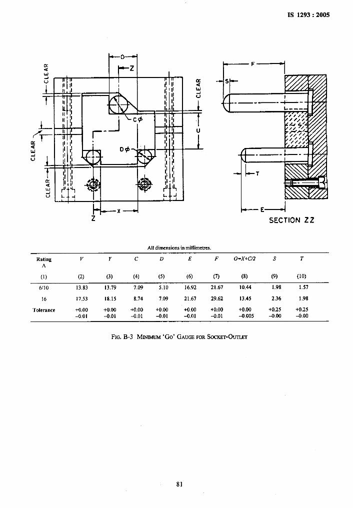
IS 1293:2005
-o-
-zi 1
n II u
II IIII
+ r A.II ,1IqII, IiII II i Y
LA II I I-J
I
All dimensions in mil[imetres.
E%-+l--=-l
SECTION 22
Rating v Y c D E F o=x+c/2 s TA
(1) (2) (3) (4) (5) (6) (7) (8) (9) (lo)
,,,
6/10 13.83 13.79 7.09 5.10 16.92 21.67 10.44 1.98 1.57
16 17.53 18.15 8.74 7.09 21.67 29.62 13.45 2.36 1.98
Tolerance +0.00 +0.00 +0.00 +0.00 +0.00 +0.00 +0.00 +0.25 +0.25
-0.01 -0.01 -0.01 -0.01 -0.01 -0.01 4.005 -0.00 -0.00
‘,>
FIG. B-3 MINIMUM‘Go’ GAUGEFORSOCKET-OWT
81
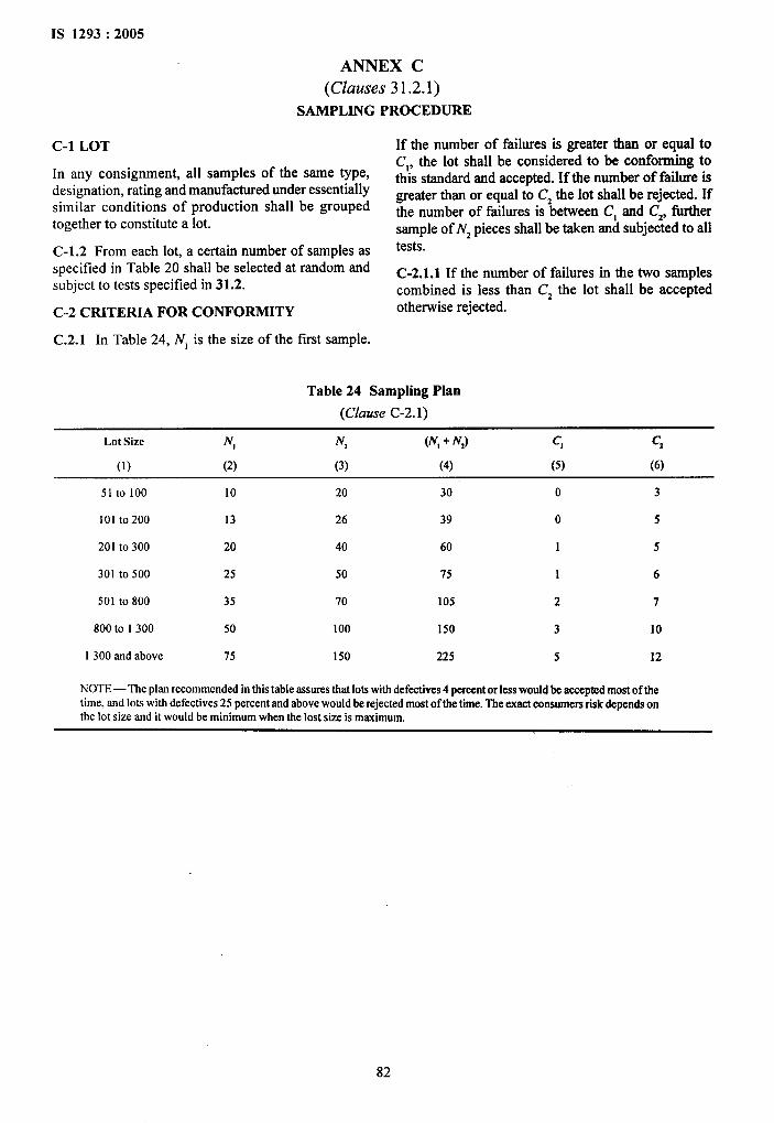
IS 1293:2005
r
,:. .. .
ANNEX C
(Clauses 31.2.1)
SAMPLING PROCEDURE
C-1 LOT
In any consignment, all samples of the same type,designation, rating and manufactured under essentiallysimilar conditions of production shall be groupedtogether to constitute a lot.
C-1.2 From each lot, a certain number of samples asspecified in Table 20 shall be selected at random andsubject to tests specified in 31.2.
C-2 CRITERIA FOR CONFORMITY
If the number of failures is greater than or equal toC,, the lot shall be considered to be conforming tothis standard and accepted. If the number of failure isgreater than or equal to C2 the lot shall be rejected. Ifthe number of failures is between Cl and Cz, furthersample of Nz pieces shall be taken and subjected to alltests.
C-2.1.1 If the number of failures in the two samplescombined is less than C2 the lot shall be acceptedotherwise rejected.
C.2.1 In Table 24, N, is the size of the fust sample.
Table 24 Sampling Plan
(Clause C-2.1)
Lot Size N, N, (N,+ N,) c, c,
(1) (2) (3) (4) (5) (6)
51 to 100 10 20 30 0 3
101 to200 13 26 39 0 5
201 to 300 20 40 60 1 5
301 to 500 25 50 75 1 6
501 to 800 35 70 105 2 7
800 to 1300 50 100 150 3 10
1300 and above 75 150 225 5 12
NOTE— The plan recommended in this table assures that lotswith defective 4 percent or less would be accepted most of thetime, and lots with defective 25 percent and above would be rejected most of the time. The exact consumers risk depends onthe lot size and it would be minimum when the lost size is maximum.
,
82
Bureau of Indian Standards
BIS is a statutory institution established under the Bureau of Indian Standards Act, 1986 to promoteharmonious development of the activities of standardization, marking and qualhy certification of goods and
attending to connected matters in the country.
Copyright
BIS has the copyright of all its publications. No part of these publications may be reproduced in any formwithout the prior permission in writing of BE3. This does not preclude the free use, in the course of implementing
the standard, of necessary details, such as symbols and sizes, type or grade designations. Enquiries relating to
copyright be addressed to the Director (Publications), BIS.
Review of Indian Standards
Amendments are issued to standards as the need arises on the basis of comments. Standards are also reviewedperiodically; a standard along with amendments is reaffirmed when such review indicates that no changes areneeded; if the review indicates that changes are needed, it is taken up for revision. Users of Indian Standardsshould ascertain that they are in possession of the latest amendments or edition by referring to the latest issue of‘BIS Catalogue’ and ‘Standards: Monthly Additions’.
This Indian Standard has been developed from Dot: No. ET 14 (5223).y~
Amendments Issued Since Publication ~.1
Amend No. Date of Issue Text Affected)
BUREAU OF INDIAN STANDARDS
Headquarters:
Manak Bhavan, 9 Bahadur Shah Zafar Marg, New Delhi 110002Telephones: 23230131,23233375,2323 9402 website : www.bis.org.in
Regional Offices: Telephones
Central :
Eastern :
Northern :
Southern :
Western :
Branches :
Manak Bhavan, 9 Bahadur Shah Zafar Marg{
23237617NEW DELHI 110002 23233841
?1/14 C.I.T. Scheme VII M, V.I.P. Road, Kankurgachi
,,
{23378499,23378561
KOLKATA 700054 23378626,23379120
SCO 335-336, Sector 34-A, CHANDIGARH 160022
{
2603843
2609285
C.I.T. Campus, IV Cross Road, CHENNAI 600113{
22541216,22541442-22542519,22542315
Manakalaya, E9 MIDC, Marol, Andheri (East){
28329295,28327858MUMBAI 400093 28327891,28327892
AHMEDABAD. BANGALORE. BHOPAL. BHUBANESHWAR. COIMBATORE. FARIDABAD.
GHAZIABAD. GUWAHATI. HYDERABAD. JAIPUR. KANPUR. LUCKNOW. NAGPUR.NALAGARH. PATNA. PUNE. RAJKOT. THIRUVANANTHAPURAM. VISAKHAPATNAM.
Printed at Simco %lnting Press, Delhi
AMENDMENT NO. 1 AUGUST 2006TO
IS 1293:2005 PLUGS AND SOCKET-OUTLETS OFRATED VOLTAGE UP TO AND INCLUDING 250VOLTS
AND RATED CURRENT UP TO AND INCLUDING. 16AMPERES — SPECIFICATION
( Thud Revision)
( Page 78,CO11, row 8 ) —.Delete.
(ET14)
ReprographyUni\ BIS,NewDelhl,Itiia
,-----. .. .. .
%
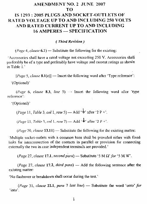
AillENDMENT NO. 2 JUNE 2007TO
IS 1293:2005 PLUGS AND SOCKET-OUTLETS OFRATED VOLTAGE UP TO AND INCLUDING 250 VOLTS
AND RATED CURRENT UP TO AND INCLUDING16 AMPERES — SPECIFICATION
( Third Revision)
(Page 4, clause 6.1) — Substitute the following for the existing:
‘Accessories shall have a rated voltage not exceeding 250 V. Accessories shallpreferably be of a type and preferably have voltage and current ratings as shownin Table 1.’
[Puge 5, clause S.I(e)] — Insert the following word after ‘Type reference’:
‘(Optional)’
(Page 6, clause 8.3, line 5) —reference’:
‘(Optional)’
(Page 11, Table 3, CO1I, row 5) —
(Page 11, Table 3, CO11, row 7) —
Insert the following word after ‘type
Add4’ after’2 P +’
Add ’1’ after ‘2 P +’
(Page 20, clause 13.1 1) — Substitute the following for the existing matter:
‘Multiple socket-outlets with a common base shall be provided either with fixedlinks for interconnection of the contacts in parallel or provision for connectingexternally the two in case independent terminals are provided.’
(Page 27, cluuse 17.1, second puru) — Substitute ‘5 M !2’ for ‘5 M W’.
(Page 27, clause 17.2, third para) — Add the following sentence after theexisting matter:
‘No flashover or breakdown shall occur during the test.’
(Page 31, clause 22.1, para 7 last line) — Substitute the word ‘onto’ for‘into’.
1
..
●
....
‘,d
‘i
I
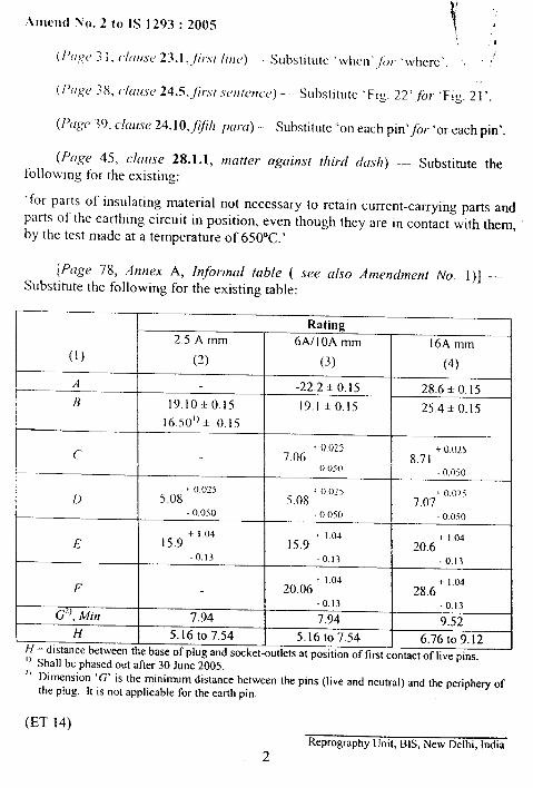
\,
,,
.\IllCIld No. 2 to 1S 1293:2005
#(/’([~(’ ~ i , (/{lf[.YC>23.1,,/i/.\/ /ire,) — S(]bst]tL[tc ‘wIIc.11’ /(), ‘\vhcre’, ~ ~
(P{Igc, 38, c/aztscJ 24.5, Jr.st .yc,ntcttcc,) -- Substitute ‘Fig. 22’Jjr ‘Fig. 2 1‘.
(P~/ge 39, clai{se 24.1 O,jjh pa}a) — Substitute ‘on each pin’~or ‘or each pin’.
(F’agc 45, claase 28.1.1, tnotter against third dash) –- Substitute thefollowing for the existing:
‘for parts of insulating material not necessary to retain current-carrying parts andpal-ts of the earthing circuit in position, even though they are in contact with them,by the test made at a temperature of 650”C.’
[Page 78, Annex A, Injotwml table ( see also Amettdrnent No. I)] –Substitute the following for the existing table:
Rating2.5 A mm 6A/1 OA mm 16A mm
(1) (2) (3) (4)
‘4 -22.2 * 0.15 28.6 * 0.15l? 19.10+0.15 19.1 *0.15 25.4+0.15
16.50’) + 0.15
ct ()Ozs +0025
7.06 8.710.05(1 -0.050
i 0.025 i 0.()?5D 5.08 5.08
+0.025
-0.0507.07
- ()050 -0.030+ I.04
E 15.9+ 1.04
15.9+ I.(34
20.6-0.13 -0.13 -0.13
+ 1.04F 20.06
+ 1.0428.6
-0.13
d)> Mi)l-0.13
7.94 7.94 9.52H 5.16 to 7.54 5.16 to 7.54 6.76 to 9.12
H = distance between the base of plug and socket-outlets at position of first contact of live pins.‘] Shall be phased out after 30 June 2005.‘1 Dimension ‘G’ is the minimum distance between the pins (live and neutral) and the periphery of
the plug. It is not applicable for the earth pin,
(ET 14)
Reprography Unit, BIS, New Delhi, India
2
,,4
,.I
I,
. .
.
,.
AMENDMENT NO. 3 OCTOBER 2007TO
1S 1293:2005 PLUGS AND SOCKET-OUTLETS OFRATED VOLTAGE UP TO AND INCLUDING250 VOLTS AND RATED CURRENT IJP TO
AND INCLUDING 16 AMPERES —SPECIFICATION
( Third Revision)
[Pag? 5, clause 8.l(h), last line] — Delete ‘,’ in between ‘even’ and ‘if’.I
(fag,? 6, clause 8.7, second line of para 2) — Substitute ‘soaked’ for I
‘socked’.
(,Page 11, clause 12.2.5, seventh line of para 5) — Substitute ‘plate’ for‘platen’.
(Page 12, clause 12.2.6, second line of para 1) — Delete ‘,’ after the word‘clamp’.
(PagcJ 15, clause 12.3.10, .Yecondline ofpara 4) — Delete the words ‘Table 7’.
[Page 17, Table 10, last line of the title) — Substitute ‘Normal Use ofScrewless Terminals’ for existing line.
(Page 21, clause 13.21, last line ofpara 1) — Add the word ‘to’ after ‘as’.I
(Page 22, clause 13.23, second line of para 2 below Table 14) — Delete ‘,’ Iafter the word ‘ageing’.
(Page 25, c[ause 14.25, last line) — Delete the words ‘shall apply’.
(Page 26, clause 16.2.1, first line of para 10) — Delete ‘operated’ afler‘Screws’.
(Puge 26, c[ause 16.2.1, last line of para 17) — Substitute ‘water if bothtypes are defined in the system’ for ‘water it both type are defined in thesystem’.
1
u’
II
Amend No. 3 to [S 1293:2005
( Puge 26, clause 16.3, [bird line of puru 2) — Substitute ‘resistance’ for‘insistence’.
(Page 30, clause 21, second line of para }6) -– Add ‘disengagement’between ‘from engagement of the plug until subsequent’ and ‘shall be’.
(Page 30, clause 21, first line of pora 27) — Add ‘,’ after the words‘socket-outlets’,
(Page 30, clause 21, second line ofpara 29) — Add the word ‘not’ betweenwords ‘and’ & ‘more’.
(Page 30, clause 22, third line of para 1) — Substitute ‘working’ for‘work’.
(Page 34, Table 20, title of col 4) –- Substitute ‘Non-rewirable Portable
Socket Out lets’ for ‘Non-rewirable Portable’ and delete ‘Cross-Section’ from
the titles of colt.umns 4 and 5.
(Page 35, clause 23.4, jirst line of last para) — Insert ‘,’ after the words‘After the test’.
(Page 38, clause 24.5, fhurtt$ line of para 1) — Substitute C150 N‘ for ’300N’. This would be phased out afler 30 June 2008.
([’age 38, clause 24.5, second line of para 2) — Substitute ‘5 rein’ for ‘1rein’. This would be phased out after 30 June 2008.
(Page 39, clause 24.10, first line of para 5) --- Substitute ‘P’/or ‘on’ afterthe words ‘A pull’.
(Page 42, clause 26.3, first line of para 1) --- Substitute ‘Electricalconnections’ for ‘Electrical connecting’.
(Page 43, clause 26.5, second line of para 1) --- Insert ‘non-ferrous’ inbetween ‘shall be of a’ and ‘metal’.
(Page 43, c[ause 26.5, para 3, item 3) — Delete ‘— stainless steelcontain ing,,, . . . . . . . . . . . . . . ...0.09 percent carbon’.
2
1“.,
Amend No. 3 to IS 1293:2005
(Page 43, cfause 26.5, para 3, item 4) —- Delete ‘–- steel providedw’ith.................25pm, for jet-proof equipment’.
(Page 83. clause 26.5, para 3, item 5) — Delete ‘-–- steel provided withan . . . . . . . . . . . . . ...40 ym, for jet proof equipment’.
(Pa~e 43, clause 26.5, para 3, item 6) — Delete ‘— steel providedwitk~. . . . . . . . . . . . . . . . ..3O pm, for jet proof equipment’.
(Page 43, clause 26.5, para 4) — Delete.
(Puge 46, clause 28.1.2, first line of Note just above clause 28.2) — Deletethe word ‘v,sicm’.
[Page 47,, clause 31.2(e)] — Delete and renumber subsequent item,
(Page 57, second line of caption below the diagram) — Substitute ‘GAUGE’
j~w ‘G(JA13E’.
(Page 58, second line below the diagram) — Add L,’ after the word‘position’ and substitute ‘as’-for ‘or’.
(Page 58, third column of the table) — Substitute ‘3.5 N’ for ‘3.5’ and‘7.2 N“ f<]r ‘7.2’.
(Page 58,, captions of Fig. 12) - Substitute ‘TEST’ for ‘FORCE’.
(Page 63, Fig. 21) — Substitute ‘24.4’ for ‘24.5’ in the captions of figure.
(Page 72. Title of col 2 of the table) — Substitute ‘Space’ for ‘Shape’.
(Page 74, footnote marked ‘l)”in table below Fig, 37) — Add ‘specifiedin’after t}le word ‘thut’.
[Page 78, Annex A, footnote ‘1)’below Table (see also Amendments No. 1017d 2)] -–- Under H 1) Substitute ‘Shall be phased out atler 30 June 2010’ for ‘Shall be
phasccl out after 30 Juw 2005’.
(Page 82, Annex C, clause C-1, first para) — Add ‘C-1.1’ before the startof the text.
3

Amend No. 3 to 1S 1293:2005
(Page 82, Annex C, clause C-1.2, pat-a 1. /ine 2) –- Substitute ‘Table 24’,jiir ‘Table 20’.
(Page 82. second and Ihird line of Note below Table 24) — Substitute‘consumer’,for ‘consumers’ and ‘kxs’ for <trots’.
(E’r 14)
Reprography Umt, BE+,New Delhi, India
4
!,, ,, ,,
. .
AMENDMENT NO. 4 DECEMBER 2009 TO
IS 1293 : 2005 PLUGS AND SOCKET-OUTLETS OF RATED VOLTAGE UP TO AND INCLUDING 250 VOLTS AND
RATED CURRENT UP TO AND INCLUDING 16 AMPERES ― SPECIFICATION
( Third Revision )
(Page 27, clause 16.3, Note 3) ― Insert the following as Note 4 at the
end:
‘4 For the purpose of acceptance test, the humidity treatment is subjected for 24 hours.’
(Page 37, clause 24.2, first para) ― Substitute the word ‘plugs’ for ‘specimen’.
(Page 41, clause 25.2, after first para) ― Add the following after the existing matter:
‘For moulded plug, resistance to heat test on inner material to be done by ball pressure test and on outer material by glow wire test till December 2009 and subsequently tests as per 25.2 and 28.1.1 will continue.’
[Page 47, clause 31.2(b)] ― Substitute the following for the existing
matter:
‘b) Resistance to harmful ingress of water and to humidity (see 16.2 and 16.3).’
(ET 14)
Reprography Unit, BIS, New Delhi, India

AMENDMENT NO. 5 AUGUST 2011TO
IS 1293 : 2005 PLUGS AND SOCKET-OUTLETS OF RATED VOLTAGE UP TO AND INCLUDING250 VOLTS AND RATED CURRENT UP TO 16 AMPERES — SPECIFICATION
(Third Revision)
(Page 35, clause 23.4) — Delete the following para:
‘The voltage drop between each contact and the corresponding conductor, with a test current flowinghaving a value as prescribed for 21, shall not exceed 10 mV.’
[Page 78, table, col 2, Subscript 1 for (B) (see also Amendments No. 1 and 2)] — Substitute thefollowing for the existing: .
‘Shall be phased out after 31 December 2011.’
(ET 14)
Reprography Unit, BIS, New Delhi, India