irc wall bracing: combined wind uplift and shear loa …/media/files/reports/expert meeting...
TRANSCRIPT

IRC WALL BRACING: COMBINED WIND
EXPERT MEETING
IRC WALL BRACING: WIND UPLIFT AND SHEAR LOA D PATH
EXPERT MEETING SUMMARY
Prepared By: NAHB Research Center, Inc.
400 Prince George’s Boulevard Upper Marlboro, MD 20774
October 15th, 2010
D PATH


Summary of Expert Meeting on Combined Wind Uplift and Shear Load Path
NAHB Research Center, Inc. October 2010 1
INTRODUCTION
As part of a comprehensive update of the 2009 International Residential Code (IRC) wall bracing provisions, a new requirement was introduced that braced wall panels must be presumed to resist combined (simultaneous) uplift and shear loads, unless an independent continuous uplift load path is provided using hurricane ties and metal straps. This change represents a significant shift in the prescriptive wall bracing provisions, with potential impacts on prescriptive braced wall amounts, performance of conventional braced wall methods, braced wall panel connection requirements, and development of alternative bracing solutions.
The combined uplift and shear load path, however, is not well understood, particularly at the whole-house level. Existing results of whole-house tests under pure shear loading (without the uplift loading) indicate significant system effects relative to building code design calculations. Considerations for the whole-house response under combined loading include load sharing, redistribution of forces through diaphragms, contribution of finishes, and contribution of those walls and partitions not designated as braced walls. Because the wind pressures vary substantially across the building’s surfaces, loading considerations are also highly important to understanding the realistic force distribution between braced walls in a building.
An expert meeting was held on July 26th, 2010 in Leesburg, VA in an effort to gather input from industry experts on issues related to the combined uplift and shear load path requirements in the IRC wind wall bracing provisions, with particular regard to immediate research needs, testing and setup requirements, and directions for future building code development that would facilitate increased construction and design efficiency while also simplifying prescriptive provisions.
This paper summarizes the findings of that meeting. First, a brief background literature review of previous combined uplift and shear load research is presented. This background review is followed by a synopsis of the presentations on ongoing research and analysis made at the expert meeting by University of Western Ontario, American Wood Council, Simpson Strong-Tie, APA—The Engineered Wood Association, and others. Finally, a summary of the experts’ opinions and suggestions for future research needs is presented. It is envisioned that this paper will provide the basis for development of future detailed research agendas and specific test plans.
Appendix A lists the expert meeting attendees.
BACKGROUND
Crandell & Martin (2009)
This paper provides insight into the basis and justification behind the combined wind uplift and shear loading requirements new to the 2009 IRC. The main driver behind the inclusion of these combined loading requirements was the difficulty of quantifying the effects of combined uplift and shear load on the partial restraint of braced wall panels within an actual building. The principal difficulty arises from the variations in location and magnitude of wind uplift loads during a wind event, coupled with the complexity of the combined load path of conventional wood construction. The ICC Ad Hoc Wall Bracing committee recognized this difficultly and despite investigating the results of several whole building tests subjected to both lateral and uplift wind
Summary of Expert Meeting on Combined Wind Uplift and Shear Load Path
October 2010 NAHB Research Center, Inc. 2
loads, the committee was unable to reach a consensus regarding an appropriate partial restraint factor that accounts for the effects of combined loading. As a result, the provisions of the 2009 IRC were added to address the wind uplift load path.
Scoville (2005)
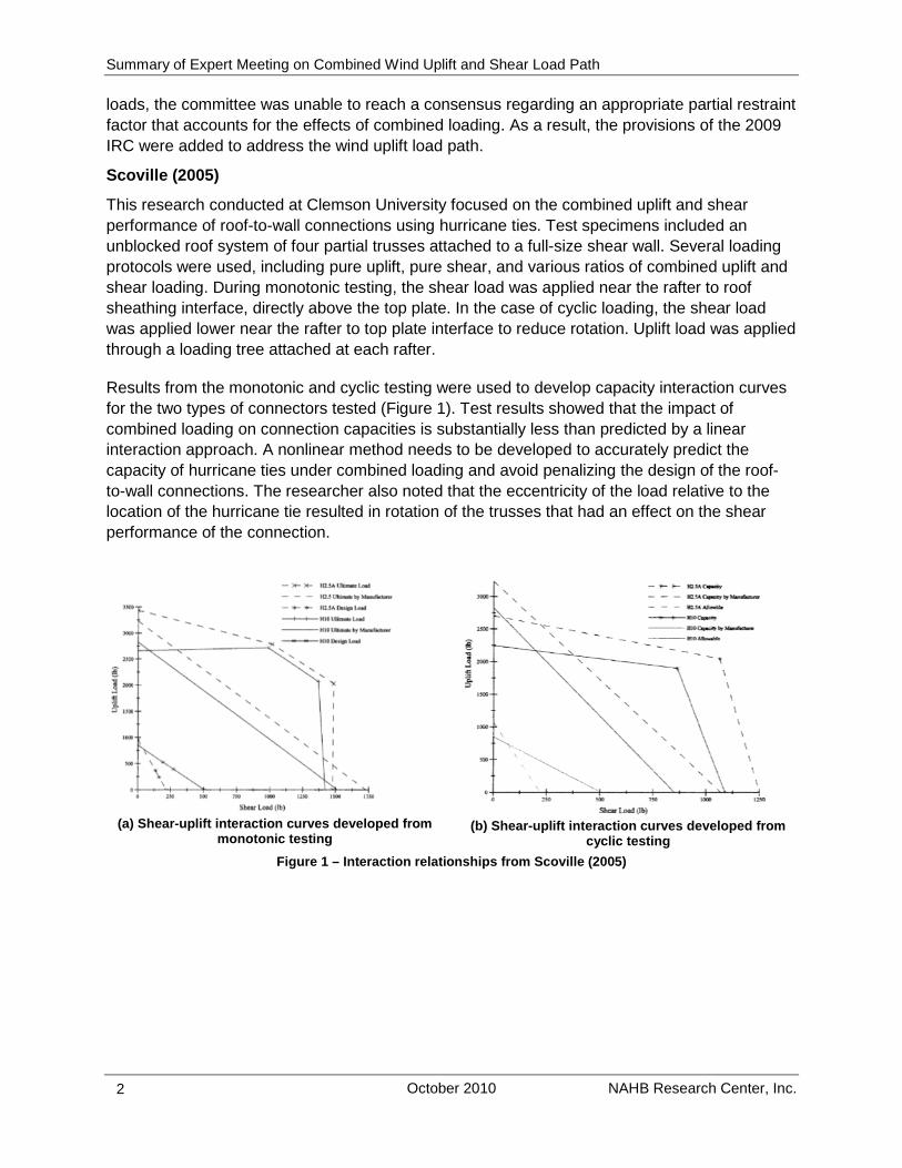
This research conducted at Clemson University focused on the combined uplift and shear performance of roof-to-wall connections using hurricane ties. Test specimens included an unblocked roof system of four partial trusses attached to a full-size shear wall. Several loading protocols were used, including pure uplift, pure shear, and various ratios of combined uplift and shear loading. During monotonic testing, the shear load was applied near the rafter to roof sheathing interface, directly above the top plate. In the case of cyclic loading, the shear load was applied lower near the rafter to top plate interface to reduce rotation. Uplift load was applied through a loading tree attached at each rafter.
Results from the monotonic and cyclic testing were used to develop capacity interaction curves for the two types of connectors tested (Figure 1). Test results showed that the impact of combined loading on connection capacities is substantially less than predicted by a linear interaction approach. A nonlinear method needs to be developed to accurately predict the capacity of hurricane ties under combined loading and avoid penalizing the design of the roof-to-wall connections. The researcher also noted that the eccentricity of the load relative to the location of the hurricane tie resulted in rotation of the trusses that had an effect on the shear performance of the connection.
(a) Shear-uplift interaction curves developed from
monotonic testing
(b) Shear-uplift interaction curves developed from
cyclic testing Figure 1 – Interaction relationships from Scoville (2005)

Summary of Expert Meeting on Combined Wind Uplift and Shear Load Path
NAHB Research Center, Inc. October 2010 3
Simpson Strong-Tie (2010)
As a follow up to the testing conducted by Scoville in 2005, additional research was conducted by Simpson Strong-Tie at Clemson to evaluate several different types of connectors loaded in three directions simultaneously, in order to develop more accurate interaction equations. Single connector test specimens replicating a typical roof-to-top plate connection detail were subjected to monotonic loading in two shear directions (in and out of the plane of the wall) and in the uplift direction.
Results of the testing program were compared to three dimensional design interaction equations assuming either planar or cube shaped design spaces to determine the largest design space volume (i.e., the highest capacities in all three directions) that still provides an acceptable probability of exceedance compared to tested capacities. Consistent with the testing by Scoville, the results showed that a linear interaction equation is overly conservative (Figure 2). The study concluded that, for the tested connectors, 75% of the published design capacities in each direction can be used for combined loading scenarios, regardless of the ratios between loads. This is particularly advantageous in scenarios where a connector is near its allowable capacity in one of the loading directions.
Figure 2 - Interaction relationships from Simpson S trong-Tie testing (2010)
Riley & Sadek (2003)
The NIST research headed by Riley and Sadek evaluated the performance of roof-to wall connections tested as part of a complete three-dimensional roof system supported by full-height walls at the heel joints. Connections were subjected to pure shear, pure uplift or a combined shear and uplift loading scenario (see Figure 3). The roof specimen was 4-foot long by 16-foot wide constructed with a total of 4 trusses at 16 inches on center connected to shear walls below using either (3) toe nails or Simpson Strong-Tie hurricane clips. Unblocked heel joints were used in all tests.
Combined Shear and Uplift on H-10 Connectors
0
100
200
300
400
500
600
700
0 200 400 600 800 1000 1200
Uplift Capacity for Individual Connector (lbs)
She
ar C
apac
ity fo
r Ind
ivid
ual
Con
nect
or (
lbs)
Pure Shear and Uplift Shear and Uplif t w ith 100 psf Out-of-Plane Loading
Vecto r Combination With Test A llowables
Linear With Test A llowables
Linear With M anufacturer's A llowables

Summary of Expert Meeting on Combined Wind Uplift and Shear Load Path
October 2010 NAHB Research Center, Inc. 4
Figure 3 – NIST Combined Uplift and Shear Test Set- Up
Table 1 summarizes the results of monotonic testing. The primary failure mode observed in both connections was tension/withdrawal failure of the connections at the uplifting part of the roof. This failure mode was consistently observed under all three loading conditions and is attributed to the overturning of the trusses. It should be noted, however, that the shear load was applied near the top of the roof specimen as opposed to through the center of gravity or centroid of the gable end wall area as would be the case for seismic or wind loading, respectively. This loading location in combination with a very narrow roof assembly (only 4 feet long) amplified the overturning effects on the performance of the roof-to-wall connections.
Table 1 – Results of NIST (2003) Testing
Loading Scenario Connection Type Peak Uplift Capacity
(lb per connection)
Peak Shear Capacity
(lb per connection)
Uplift Only Toe-nails (3 nails) 500
Hurricane clips (4 nails) 750
Shear Only Toe-nails (3 nails) 313
Hurricane clips (4 nails) 438
Combined Loading Toe-nails (3 nails) 650 138
Hurricane clips (4 nails) 988 238
Comparison of results from combined loading tests to those in pure shear for both the toe-nailed and clip connections indicates that application of shear wall loading at about 50 percent of maximum results in an increased uplift capacity of about 30 percent when compared to an uplift-only scenario. In the toe-nailed connections, this increase may be due to additional friction between the nails and the top plate caused by the lateral loading.

Summary of Expert Meeting on Combined Wind Uplift and Shear Load Path
NAHB Research Center, Inc. October 2010 5
EXPERT MEETING PRESENTATIONS
Research at the University of Western Ontario
The presentation by Dr. Kopp of the University of Western Ontario (UWO) briefly reviewed the development of the current ASCE 7 wind pressure coefficients, then focused on wind loading as it pertains to residential structures and recent findings from the Three Little Pigs Project being conducted at the Insurance Research Lab for Better Homes in London, Ontario, CA. The Three Little Pigs Project is a full-scale testing project to investigate the performance and behavior of a whole-house specimen subjected to wind loading. Figure 4 provides a photograph of the building specimen and testing apparatus.
Figure 4 – Three Little Pigs Project house and reac tion frame
In particular, the presentation highlighted the large spatial and temporal variability in wind pressures acting upon a typical residential roof system during a wind event. Wind tunnel research conducted at the UWO as part of the Three Little Pigs Project showed that the magnitude and location of peak uplift pressures on a gable roof system varied greatly throughout a typical wind event. Figure 5 illustrates the variation in magnitude of uplift pressures. It should be noted that the peak uplift pressures are measured for relatively small areas and as the tributary area is increased, area-averaging effects reduce the peak pressures over the area in question. Figure 5 also presents the effect of a rigid versus flexible diaphragm assumption on the amount of load observed at a single roof-to-wall connection (Inset B, lower left corner). Additionally, the research showed that the shape of the roof has an impact on the magnitude of uplift pressures as well, with a gable roof inducing higher uplift pressures compared to a hip roof.

Summary of Expert Meeting on Combined Wind Uplift and Shear Load Path
October 2010 NAHB Research Center, Inc. 6
Figure 5 – Spatial variations in roof wind pressure (image taken from presentation by Dr. Kopp)
Recently completed testing on the Three Little Pigs Project full-scale house replicated these variations in uplift pressures by using 56 Pressure Loading Actuators (PLA) arranged in a grid formation over the entire roof. The PLAs induced wind pressures in accordance with the observed wind tunnel pressure time history for several different wind speeds and the corresponding behavior at the roof to wall connection was recorded. Displacement and applied loading results indicated that significant load-sharing occurred. The observed degree of load sharing indicated that the overall roof system behavior can be classified as semi-rigid.
Also discussed was the applicability of the ASCE 7 internal pressure coefficients developed based on modeling of structures with small opening to interior volume ratios to the larger ratios which typically exist in a home. Research presented by Kopp in the ASCE Journal of Structural Engineering in 2008 found that internal pressure coefficients for a typical size home with large window openings can be as much as three times the magnitude specified in ASCE 7. This effect may have implications on uplift loading scenarios where the internal pressure is added to the external suction (as opposed to the case of lateral MWFRS loads where the internal pressure exerts force on both faces of the building and the resultant force is taken as zero).
Analytical Modeling of Combined Uplift and Shear
Brad Douglas of the American Wood Council presented a mechanics-based wood-shear wall model that accounts for varying restraint conditions in a shear wall by modeling the interaction of individual shear wall segments through both fastener shear transfer as well as bearing transfer at the corners of sheathing above and below adjacent openings. The model can also account for the effect of an uplift load on the lateral capacity of the shear wall.
Applicability of this model was verified against test results from a number of different shear wall configurations including perforated shear walls with and without hold-downs, portal frames and high aspect ratio shear walls and shear walls subject to combined shear and uplift loading. The ultimate capacities predicted by the model showed good correlation for every shear wall configuration evaluated. Figure 6 provides sample comparison graphs illustrating the correlation of predicted to actual wall capacities.

Summary of Expert Meeting on Combined Wind Uplift and Shear Load Path
NAHB Research Center, Inc. October 2010 7
(a) Perforated shear wall with hold-downs
(b) Perforated shear wall without hold-downs
(c) High aspect ratio shear wall
(d) Combined shear and uplift loading shear wall
Figure 6 – Comparison of shear capacities predicate d by model to shear wall test results
Combined Uplift and Shear Testing Conducted By APA
BJ Yeh of APA presented the background testing and methods of analysis used to develop APA’s Design for Combined Shear and Uplift from Wind System Report (SR-101B). This document provides a method for using shear wall panels to resist uplift loads imposed on the wall by providing additional sheathing nailing at the top and bottom plates. The premise of this approach is that the additional nails installed in the top and bottom plates offset the effect of the uplift force on the shear wall capacity. This behavior model was validated through testing of 8-foot by 8-foot shear walls anchored at 16-inches on center subjected to either uplift loads only or combined loading. Failure analysis of initial tests indicated that, despite the close anchor spacing, metal plate washers were required to prevent a cross-grain bending failure mode.
An additional testing program was conducted to investigate the use of greater anchor bolt spacing in an effort to provide increased flexibility and improved constructability. The initial
0
1000
2000
3000
4000
5000
6000
7000
0 1000 2000 3000 4000 5000 6000 7000
Pre
dict
ed S
hear
Cap
acity
(lbf
)
Observed Shear Capacity (lbf)
Swedish National Testing & Research Institute(perforated shearwall tests)
0
5,000
10,000
15,000
20,000
25,000
30,000
35,000
40,000
0 5,000 10,000 15,000 20,000 25,000 30,000 35,000 40,000
Pre
dict
ed S
hear
Cap
acity
(lbf
)
Observed Shear Capacity (lbf)
AWC Mechanics Model VPI TE-1997-002 Perforated Shear Wall Tests
1000
1500
2000
2500
3000
3500
1000 1500 2000 2500 3000 3500
Pre
dict
ed S
hear
Cap
aci
ty (l
bf)
Observed Shear Capacity (lbf)
AWC Mechanics Model (WSU-WMEL 05-069)
0
1000
2000
3000
4000
5000
6000
7000
8000
9000
10000
0 1000 2000 3000 4000 5000 6000 7000 8000 9000 10000
Pre
dic
ted
Sh
ea
r C
ap
aci
ty (lb
f)
Observed Shear Capacity (lbf)
AWC Mechanics Model (Payeur & Salenikovich, 2009)
8'
16'

Summary of Expert Meeting on Combined Wind Uplift and Shear Load Path
October 2010 NAHB Research Center, Inc. 8
testing and development of the nailing schedules and anchorage requirements in SR-101B assumed that the shear wall is loaded to its full capacity in both the lateral and vertical directions. This load scenario, however, is not present in many design situations. By assuming a linear relationship between anchorage spacing and uplift/lateral load demands, the bolt spacing was increased to up to 48 inches for situations with lower shear and/or uplift demand. This method was validated by additional testing of 14 wall configurations with varying nail sizes and spacing. The end results of these efforts are the current tabulated design capacities, fastener/anchorage spacing and construction details in SR-101B.
Combined Uplift and Shear Testing Conducted By Simp son Strong-Tie
Randy Shackelford of Simpson Strong-Tie presented the results of two research programs conducted at Simpson’s laboratory facility in Stockton, CA. The first program compared the combined loading performance of wood shear walls utilizing the additional nailing schedule outlined in APA’s SR-101B with the performance of a standard nailing schedule shear wall augmented with metal straps to create a continuous uplift load path. Results showed that both methods provided adequate uplift resistance to allow the walls to exceed the design racking strength of the standard nailing schedule shear wall. Analysis of the failure modes of shear walls nailed in accordance with APA SR-101B also indicated that the size and thickness of the plate washers has a significant role in preventing lower capacity failures due to cross-grain bending.
The second research program focused on the eccentric loading condition that occurs in a roof-to-wall connection when metal strapping is used to create the uplift load path. Typically, the metal straps are installed on the interior face of the top plates; the continuation of the load path, however, is through the exterior sheathing on the opposite face of the top plate. When subjected to uplift, this eccentric configuration creates rotation in the top plate that may lead to premature connector failures. As an alternative, Simpson developed and tested a detail where stud-to-top plate connectors are used intermittently along the length of the wall to resist the rotation of the top plate. Results showed that an H10 connector installed on the interior face of the top plates, when used in combination with stud-to-top plate connection detail, exhibits only a 20% decrease in uplift capacity.
IRC Roof Blocking Requirements – Opportunities for Optimization
Gary Ehrlich of NAHB presented a summary of the history behind the current IRC roof blocking requirements and discussed questions that still need to be answered regarding further development and implementation of roof blocking. As part of the 2006 IRC development cycle, a proposal was submitted requiring full-height blocking. After two code development cycles and extensive discussion between the proponent, the ICC Ad-Hoc Wall Bracing committee, the Structural Building Components Association, and the National Association of Home Builders, a substantially-revised proposal was approved for the 2009 IRC. Depending on rafter/ceiling joist or truss heel height, basic wind speed, and seismic design category, the IRC now requires partial-height blocking, blocking panels, or engineered truss blocking at exterior walls as shown in Table 2:

Summary of Expert Meeting on Combined Wind Uplift and Shear Load Path
NAHB Research Center, Inc. October 2010 9
Table 2 – Summary of 2009 IRC Roof Framing Blocking Requirements
Triggers
Minimum Requirements Notes
Wind/Seismic Roof Configuration
Wind less than 100 mph and SDC A, B, C
Rafter or truss heel joint 9-1/4 or less
Nailed connection per IRC Table R602.3(1)
At each heel joint along the
length of the entire wall
Rafter heel joint height 9-1/4”—15-1/4”
Nailed connection per IRC Table R602.3(1) AND Partial height blocking nailed to wall top plate
Blocking is only at the braced
wall panel
Truss heel joint height 9-1/4”—15-1/4”
Trusses attached per IRC Sections R802.10 and R802.11 AND Partial height blocking nailed to wall top plate
Wind 100 mph or greater and SDC D0, D1, D2
Rafter or truss heel joint height up to 15-1/4”
Nailed connection per IRC Table R602.3(1) AND Partial height blocking nailed to wall top plate
All wind speeds and all SDCs
Rafter or truss heel joint exceeds 15-1/4”
Options: (1) Blocking at overhang and at top plate per Figure R602.10.6.2(2) (2) Partial height blocking with wall panels per Figure R602.10.6.2(3) (3) Engineered full-height blocking panels nailed to roof sheathing (blocked diaphragm) (4) Other engineered methods
However, questions still persist regarding the optimum combination of roof-to-wall connection details including blocking spacing, blocking height, and triggers for blocking. In addition, details are needed to address the transfer of forces at interior braced wall lines.
SUMMARY OF MEETING DISCUSSION
The following is a summary of the combined wind uplift and shear load path issues that were discussed by the experts during the meeting, including the particular areas where the group felt that further research would be beneficial:
• Several experts expressed support for further research into wind pressure profiles on a typical residential structure, particularly with regard to reconciling the temporal and spatial correlations between shear and uplift loads for both the envelope and directional methods. Also, a question was raised on how envelope pressure profiles account for system response characteristics that are specific to residential structures (i.e., need to

Summary of Expert Meeting on Combined Wind Uplift and Shear Load Path
October 2010 NAHB Research Center, Inc. 10
define a structural influence function(s)). There was general agreement amongst the experts present that the peak uplift and peak shear forces may not occur at the same time and place during a wind event. However, current codes assume that these maximum shear and uplift loads occur simultaneously, which can lead to overly conservative designs when evaluating combined loading scenarios. Also noted was how the assumed diaphragm stiffness has an effect on the forces present at individual roof connections, with the force coefficients varying by as much as a factor of 2.5 depending on whether the diaphragm is flexible or rigid . Accurate determination of the actual loads occurring at discrete time intervals during a wind event is crucial in order to produce practical and economical structural designs.
• The building shape and roof configuration was noted as having a significant effect on the performance of the building during a wind event. In particular, the UWO research showed that a hip roof configuration tended to produce lower pressure coefficients when compared to a typical gable roof configuration.
• Another topic noted by the group was possibly un-conservative values for ASCE 7 internal pressure coefficients. Research presented at the meeting indicated that the actual internal pressure coefficients for a residential structure may be as much as 3 times higher than the coefficients currently specified by code. This discrepancy was attributed to the fact that the ASCE 7 internal pressure coefficients were determined from building models that had larger interior air volumes compared to the area of openings in the walls. Residential structures have a much lower interior volume to opening area ratio, making them much more susceptible to the effects of internal pressure changes. This effect is of particular interest when determining uplift performance where the internal pressure acting on the roof is added to the roof suction pressures.
• It was recognized that there is a need for whole-house performance testing and research. Many agreed that the testing of whole-house specimens is necessary in order to benchmark the system performance of residential structures that are currently allowed by the IRC, including the performance characteristics of un-symmetric buildings. Single component test results could then be calibrated to the system performance, which would in turn allow for simple, yet accurate analysis of new component options in the future. Some experts also mentioned the need to evaluate the performance of structures that are more representative of actual construction; in essence to provide a beta test of actual houses that utilize historically accepted or “conventional” building practices that may not necessarily be found in the code.
• One expert suggested that a “weak link” approach be taken whereby additional design and detailing could be applied at key points where it would be needed most. For example, if the locations where the greatest peak wind uplift loads occur are identified, additional metal strapping can be placed in those locations. If properly sized to account for both uplift and shear overturning, these straps can serve a dual purpose. This approach can also be readily incorporated into prescriptive provisions, by providing details that would be triggered only when necessary and located only in discrete locations within the building system. Additional whole-house or system performance

Summary of Expert Meeting on Combined Wind Uplift and Shear Load Path
NAHB Research Center, Inc. October 2010 11
research to identify the system’s weak links is integral and necessary to properly apply this approach.
• Several possible methods were presented for resisting the combined uplift and shear load, including:
o Using additional braced wall or shear wall panels to compensate for the uplift load;
o Using additional metal connectors or light-gage strapping within the braced wall panel construction to resist the uplift force. This solution has been shown to provide adequate uplift restraint to allow braced walls to exceed segmented shear wall capacities while resisting uplift forces (as exhibited by Simpson Strong-Tie research presented above and by testing conducted at the NAHB Research Center); and,
o Counting the contribution of the interior gypsum sheathing in the uplift load path. For this method, however, the orientation of the board becomes an important factor because of the difference in the load transfer capacity between the cut and the tapered edges of the panel (fasteners placed near a cut gypsum edge have less tear capacity than fasteners at the tapered edges). Also, conventional gypsum application practices do not always include attachment of the gypsum to the top plates of the wall, further affecting the uplift capacity of the sheathing.
• The issue of complexity of the IRC wall bracing provisions was discussed and resonated
with building code officials with regard to both implementation to realistic home designs and enforcement of compliance in the field. Development of simplified/streamlined prescriptive provisions was identified as a priority. One solution discussed included reaching agreement on practical limitations for conventional construction practices based on hazard levels and typical home configurations that would allow the use of simpler design provisions more aligned with historical practice.
• Several questions were raised regarding the combined uplift and loading path, such as: o What is the effect of this design concept on the present design methodology
used for concrete anchors in residential construction? If the braced wall panels are now going to be designed for a combined shear and uplift load, shouldn’t the anchors also be designed for combined loading?
o What is the contribution of the ceiling sheathing to a conventional, unblocked roof diaphragm?
o What is the load transfer mechanism for interior braced walls? How does the load get transferred from the roof diaphragm to the top of the wall?
o Has any research been done on the overturning performance of blocking details for roofs with I-Joist framing members?
• Several experts articulated some disparagement regarding the current blocking details for roof-to-wall connections found in the IRC, citing the complexity and constructability of the details as issues. One suggestion was to research possible K- or X-type bracing between the roof members to resist the overturning moments developed.

Summary of Expert Meeting on Combined Wind Uplift and Shear Load Path
October 2010 NAHB Research Center, Inc. 12
• A discussion was also held regarding the use of forensic research to help shed light on combined loading issues. In particular, could investigation of structural damage caused by wind events be used to determine the actual load paths and building performance? The general consensus was while this is certainly a possibility, it may prove difficult. Primarily, the difficulties in forensic research of wind events stem from the inability to accurately determine failure modes within the building. Extensive research has been done by the insurance community into roof failure at the cladding level, but that data is often not complete enough to determine component level behavior/failure. Also, any determination of behavior obtained from the investigation and performance of in-situ construction must consider the level of construction adequacy. In other words, was the home built correctly in the first place? Is the observed failure due directly to the wind event or is it a factor of poor construction quality?
• Lastly, the topic of modeling was discussed with a focus on the need to develop accurate models that account for all facets of structural performance, including the system effects often present in residential construction. The principal benefit to accurate modeling is that it reduces the need for future whole system testing by instead integrating results from component testing into the model to produce the whole-system performance. That being said, it was also recognized that initial verification research at the system level is necessary to validate any models that are developed.
SUMMARY
This expert meeting was convened to identify gaps in knowledge and to establish directions for research on the issue of combined uplift and shear load paths in residential construction. The importance of this topic has been recently amplified due to the new more stringent IRC wall bracing requirements. The focus of the discussion was on the wind load issues and interaction of the wind load with the structure. Several priorities were identified at the meeting including:
• development of wind pressure profiles specific to residential building configurations; • understanding the interaction between the structure’s characteristics (e.g., stiffness,
geometry) and the load applied to its systems and elements; • understanding internal pressures for building configurations with large exterior openings
as typical in homes; • understanding and benchmarking whole-house building performance under realistic
loading; • establishing the degree of temporal correlation between shear and uplift loads; and, • optimizing the roof blocking requirements.
These research areas represent the greatest potential for developing structural solutions that provide for safe, practical, and economical residential construction technologies.

Summary of Expert Meeting on Combined Wind Uplift and Shear Load Path
NAHB Research Center, Inc. October 2010 13
REFERENCES
APA – The Engineered Wood Association. 2010. Design for Combined Shear and Uplift from Wind (SR-101B). www.apawood.org. Tacoma, WA: Author.
Crandell, J. & Martin, Z., 2009. The Story Behind the 2009 IRC Wall Bracing Provision (Part 2: New Wind Bracing Requirements). Madison, WI: Forest Products Society.
Kopp, G., Oh, J. H., & Inculet, D., 2008. Wind-Induced Internal Pressures in Houses. ASCE Journal of Structural Engineering. Reston, VA. American Society of Civil Engineers.
International Code Council. 2009. International Residential Code for One and Two Family Dwellings. Country Club Hills, IL: Author.
Morrison, M. 2010. Response of a Two-Story Residential House Under Realistic Fluctuating Wind Loads. London, Ontario, CA: University of Western Ontario.
Riley, M. & Sadek, F. 2003. Experimental Testing of Roof-to-Wall Connections in Wood Frame Houses (NISTIR 6938). Gaithersburg, MD: Building and Fire Laboratory, National Institute of Standards and Technology.
Scoville, E., 2005. Investigation of the Response of Low-Rise Wood-Frame Roof-Wall Systems Under Combined Uplift and In-Plane Shear Loads. Clemson, SC: Clemson University.
Simpson Strong-Tie. 2010. Truss Anchorage for Multiple Loading. PowerPoint Presentation of Testing Conducted at Clemson University, Randy Shackelford of Simpson Strong-Tie, Personal Communications.
U.S. Department of Housing and Urban Development (HUD). 2002. Roof Framing Connections in Conventional Residential Construction – Task 2. Prepared by the NAHB Research Center. Upper Marlboro, MD: NAHBRC.

Summary of Expert Meeting on Combined Wind Uplift and Shear Load Path
October 2010 NAHB Research Center, Inc. 14
APPENDIX A
Name Company
Louis Wagner American Fiberboard Association (AFA) Jeff Linville American Institute of Timber Construction (AITC) Loren Ross American Wood Council (AWC)
Peter Mazikins American Wood Council (AWC) Brad Douglas American Wood Council (AWC) Jeff Stefani Anthony Forest Products
BJ Yeh APA—The Engineered Wood Association Jesse Dayhoff Apex Technology Jay Crandell ARES Consulting Gary Dunn Boise Cascade
Helen Griffin Canadian Wood Council Robert Jonkman Canadian Wood Council (CWC) Peggy Lepper Canadian Wood Council (CWC)
Charles Nyberg Chesterfield County, VA Chuck Bajnai Chesterfield County, VA Chris Snidow County of Henrico, VA
Chun Ni FPInnovations Jason Smart ICC Evaluation Service
Russ Krivchuk ICC Evaluation Service Anne Cope Institute for Business and Home Safety (IBHS) Mark Bartel International Beams Teo Saralde Louisiana-Pacific Corp. Gary Ehrlich National Association of Home Builders (NAHB)
John Haluska Norbord Industries David Lewis Norbord Industries Philip Brazil Reid Middleton
Randy Shackelford Simpson Strong-Tie Cathy Marx Kaake Southern Forest Products Association (SFPA)
Kirk Grundahl Structural Building Components Association (SBCA);
Qualtim
Vijaya Gopu University of New Orleans (UNO) & Louisiana Transportation
Research Center (LTRC) Greg Kopp University of Western Ontario (UWO) Phil Line URS Corporation
Doug Rammer USDA Forest Products Laboratory Kevin Cheung Western Wood Products Association (WWPA) Dan Cheney Weyerhaeuser Jim Mahaney Wiss Janney Elstner