design manual - johns building...
TRANSCRIPT
AUSTRALIAAPRIL 2006
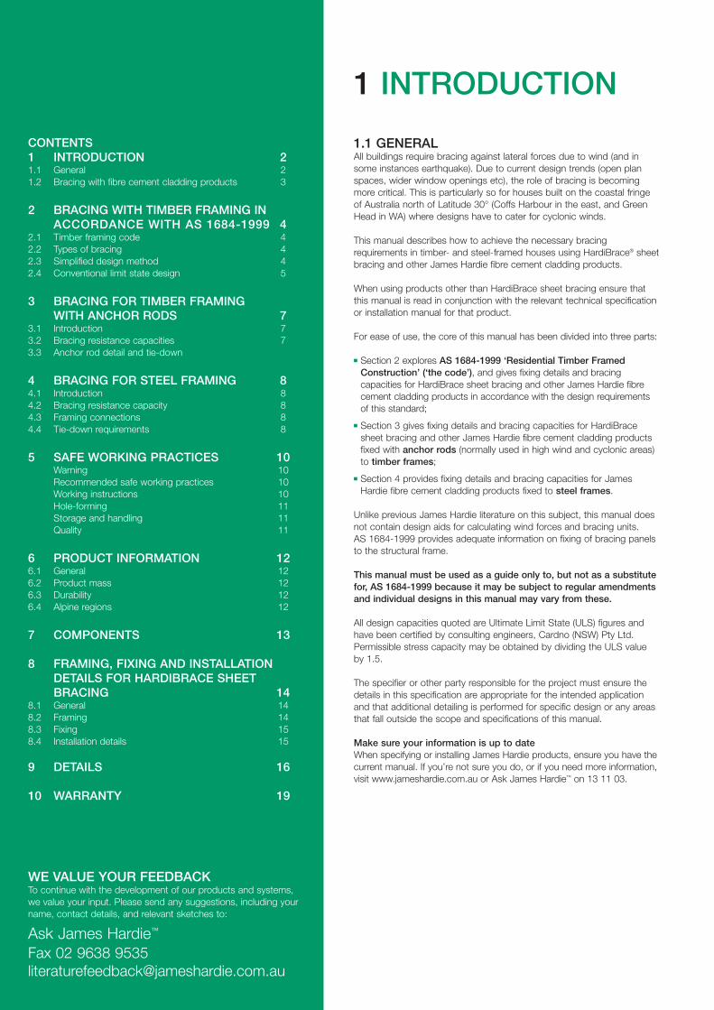
DESIGN MANUAL
STRUCTURAL BRACINGHARDIBRACE® SHEET BRACING, HARDIFLEX® SHEET, HARDIPLANK® WEATHERBOARD, LINEA™ WEATHERBOARD, HARDITEX® BASE SHEET, PANELCLAD® SHEET, PINERIDGE® LINING, VERSILUX® LINING AND VILLABOARD® LINING
1 INTRODUCTION
1.1 GENERALAll buildings require bracing against lateral forces due to wind (and insome instances earthquake). Due to current design trends (open planspaces, wider window openings etc), the role of bracing is becomingmore critical. This is particularly so for houses built on the coastal fringeof Australia north of Latitude 30° (Coffs Harbour in the east, and GreenHead in WA) where designs have to cater for cyclonic winds.
This manual describes how to achieve the necessary bracingrequirements in timber- and steel-framed houses using HardiBrace® sheetbracing and other James Hardie fibre cement cladding products.
When using products other than HardiBrace sheet bracing ensure thatthis manual is read in conjunction with the relevant technical specificationor installation manual for that product.
For ease of use, the core of this manual has been divided into three parts:
� Section 2 explores AS 1684-1999 ‘Residential Timber FramedConstruction’ (‘the code’), and gives fixing details and bracingcapacities for HardiBrace sheet bracing and other James Hardie fibrecement cladding products in accordance with the design requirementsof this standard;
� Section 3 gives fixing details and bracing capacities for HardiBracesheet bracing and other James Hardie fibre cement cladding productsfixed with anchor rods (normally used in high wind and cyclonic areas)to timber frames;
� Section 4 provides fixing details and bracing capacities for JamesHardie fibre cement cladding products fixed to steel frames.
Unlike previous James Hardie literature on this subject, this manual doesnot contain design aids for calculating wind forces and bracing units. AS 1684-1999 provides adequate information on fixing of bracing panelsto the structural frame.
This manual must be used as a guide only to, but not as a substitutefor, AS 1684-1999 because it may be subject to regular amendmentsand individual designs in this manual may vary from these.
All design capacities quoted are Ultimate Limit State (ULS) figures andhave been certified by consulting engineers, Cardno (NSW) Pty Ltd.Permissible stress capacity may be obtained by dividing the ULS valueby 1.5.
The specifier or other party responsible for the project must ensure thedetails in this specification are appropriate for the intended applicationand that additional detailing is performed for specific design or any areasthat fall outside the scope and specifications of this manual.
Make sure your information is up to dateWhen specifying or installing James Hardie products, ensure you have thecurrent manual. If you’re not sure you do, or if you need more information,visit www.jameshardie.com.au or Ask James Hardie™ on 13 11 03.
CONTENTS1 INTRODUCTION 21.1 General 21.2 Bracing with fibre cement cladding products 3
2 BRACING WITH TIMBER FRAMING INACCORDANCE WITH AS 1684-1999 4
2.1 Timber framing code 42.2 Types of bracing 42.3 Simplified design method 42.4 Conventional limit state design 5
3 BRACING FOR TIMBER FRAMINGWITH ANCHOR RODS 7
3.1 Introduction 73.2 Bracing resistance capacities 73.3 Anchor rod detail and tie-down
4 BRACING FOR STEEL FRAMING 84.1 Introduction 84.2 Bracing resistance capacity 84.3 Framing connections 84.4 Tie-down requirements 8
5 SAFE WORKING PRACTICES 10Warning 10Recommended safe working practices 10Working instructions 10Hole-forming 11Storage and handling 11Quality 11
6 PRODUCT INFORMATION 126.1 General 126.2 Product mass 126.3 Durability 126.4 Alpine regions 12
7 COMPONENTS 13
8 FRAMING, FIXING AND INSTALLATIONDETAILS FOR HARDIBRACE SHEETBRACING 14
8.1 General 148.2 Framing 148.3 Fixing 158.4 Installation details 15
9 DETAILS 16
10 WARRANTY 19
WE VALUE YOUR FEEDBACKTo continue with the development of our products and systems,we value your input. Please send any suggestions, including yourname, contact details, and relevant sketches to:
Ask James Hardie™
Fax 02 9638 [email protected]
STRUCTURAL BRACING DESIGN MANUAL APRIL 2006 3
1.2 BRACING WITH FIBRE CEMENT CLADDING PRODUCTS
Fibre cement (FC) cladding on double-sided or single-sided wall systemscan provide resistance against lateral forces or racking shear.
When fixed in accordance with this manual, and properly coated inexternal applications, thicker cladding products can provide bracingcapacity to buildings as well as serving as a wall cladding.
Apart from HardiBrace sheet bracing, the design tables in this manualprovide bracing values for other James Hardie cladding products of 6mmor greater thickness. These are:
1. 6mm HardiFlex® sheets; 2. 6mm Villaboard® and Versilux® linings;3. 6mm PanelClad® sheets and PineRidge® lining;4. 7.5mm HardiTex® base sheets;5. All thickness and widths of HardiPlank® and Linea™ weatherboards,
provided that fasteners pass through both planks (see note below).
IMPORTANT NOTEFor simplicity, items 1 to 4 will be referred to in the design tables as6mm JHFC sheets and item 5 as JHFC planks and weatherboards.
4 STRUCTURAL BRACING DESIGN MANUAL APRIL 2006
2 BRACING FOR TIMBER FRAMING IN ACCORDANCE WITH AS 1684-1999
2.1 TIMBER FRAMING CODEAS 1684-1999 ‘Residential Timber Framed Construction’ (‘the code’), isan extensive revision of the earlier code of practice. It has been issued infour parts:
Part 1: Design criteriaPart 2: Non-cyclonic areasPart 3: Cyclonic areasPart 4: Simplified non-cyclonic areas
The main change was the move to Limit State design. With regard tostructural bracing, the former Type A and Type B bracing units have beenplaced into AS 1684.4, the simplified design procedure, which is coveredin Clause 2.3 of this manual. In the simplified method, the number ofbracing units is determined directly from tables relating to the shape ofthe building and bracing units are then assigned according to the rules of the code.
Structural bracing using the conventional Limit State design method iscovered in Section 8 "Racking and Shear Forces" of both Part 2 and Part 3 of the code. This is covered in Clause 2.4 of this manual. In thismethod, the total racking force is determined from tabulated data andbracing walls are designed on the basis of their actual kN/m bracingcapacity.
Note that throughout the code the wind classifications of AS 4055 ‘WindLoads for Housing’ have been used:
� In Part 2, the pressures have been tabulated for non-cyclonic windclassifications N1 to N4 (with N5 and N6 ignored);
� In Part 3, the pressures have been tabulated for cyclonic windclassifications C1 to C3 (with C4 ignored).
2.2 TYPES OF BRACINGThe code describes two types of bracing against lateral load:
1. Nominal bracingNominal bracing is defined as (a) any wall framing lined with fibrecement sheets (or other materials) not fixed in accordance with thismanual, and/or (b) with the frames nominally fixed to the floor and theroof or ceiling frame (ie not tied down in accordance with thismanual). The capacity depends on whether the simplified designmethod (Section 2.3 of this manual) or the conventional designmethod (Section 2.4 of this manual) is used. For framing, fixing andinstallation of nominal bracing, refer to Clause 8.1.
2. Structural bracingAlso known as "designated" bracing, structural bracing is purpose-fitted bracing such as the James Hardie systems detailed in thismanual. Fixing must be as per the instructions given in this manual.
2.3 SIMPLIFIED DESIGN METHOD2.3.1 Limitations, procedure and other rulesThe simplified method given in AS 1684.4 applies only to Class 1 andClass 10 Buildings as defined by the Building Code of Australia (BCA).Clause 1.6 of AS 1684.4 elaborates these limitations as follows:
� single- and two-storey dwellings only;� a maximum wind classification of N2 (ie non-cyclonic);� a maximum width of building of 12m excluding eaves;� a maximum wall height of 2700mm;� a maximum rafter overhang of 750mm;� a maximum roof pitch of 30º;� a maximum rafter spacing of 900mm for tile roofs and 1200mm for
sheet roofs;� spacing of bracing elements not to exceed 9m;� there are certain maximum building masses for floor framing, wall
framing and roof framing.
This would cover the vast majority of homes in urban areas south of 30º latitude.
The design procedure shall be as follows:
(a) Determine wind classification using Clause 1.6 of AS 1684.4;(b) Determine the appropriate house elevation option for single or upper
storey or the lower storey of a two-storey building for both winddirections (use the code Figure 8.3);
(c) Determine the number of bracing units required for each winddirection (use the code Table 8.2);
(d) Allocate the required number of structural bracing units in conjunctionwith the amount of nominal bracing if necessary;
(e) Distribute the bracing units evenly (see the code Figures 8.4 and 8.5).
Other rules and allowances that need to be considered include thefollowing (refer to the code Clause 8.3.2.3 for full details):
� Bracing may be a combination of Type A and/or Type B structuralbracing units and/or nominal bracing;
� Nominal bracing shall not constitute more than 50% of the requiredbracing for each wind direction or in each storey;
� Where structural bracing occurs in the same section of wall as nominalbracing, the nominal bracing in that section of wall shall not beconsidered as contributing to the house bracing requirements;
� Generally a minimum of two structural bracing units (Type A or Type B)shall be provided in each overall length of external wall in each storey,located as closely as possible to the external corners (see the code forrules of exceptions);
� One Type B unit equals two Type A units;� Bracing units need to be installed at right angles to the wall area of
elevation (ie parallel to wind direction) for which the bracing was defined.
Clause 1.7(f) of AS 1684.4 states that the design capacities are 3kN per900mm for Type A bracing units and 6kN per 900mm for Type B. Theseare Ultimate Limit State (ULS) figures.
2.3.2 Nominal bracingCladding not fixed in accordance with this manual, or wall frames notconnected to the structure in accordance with this manual, is nominalbracing. Respectively a 7m length of single-sided nominal bracing or a4m length of double-sided nominal bracing constitutes one Type Abracing unit.
STRUCTURAL BRACING DESIGN MANUAL APRIL 2006 5
2.3.3 Structural BracingApart from using HardiBrace sheet bracing as structural bracing as perClauses 2.3.6 and 2.3.7 below, Type A and B units can also be achievedwith minimum 6mm thick JHFC sheets as detailed in Clause 2.3.8 of thismanual. In this simplified method, bracing units must not be less than900mm wide.
2.3.4 Bracing panels wider than 900mmBracing units are generally based on a standard width of 900mm. Forwider walls than this, the bracing capacity is increased in direct proportionto the installed width divided by 900. For example, a 1200mm widesection is equivalent to 1200/900 or 1.33 times the bracing resistance ofthe 900mm unit.
2.3.5 Tie-down requirementsIn order to provide structural bracing resistance, the bracing panels mustbe adequately tied-down to the floor system. For tie-down requirements,refer to AS 1684.4 Clause 8.3.2.7 (bottom) and Clause 8.3.2.8 (top).
2.3.6 Type A bracing unitsTo achieve Type A bracing capacity (3kN/900mm), fix the HardiBracesheet bracing in accordance with Figure 1, Section 8 and Clause 2.3.5 ofthis manual.
2.3.7 Type B bracing unitsTo achieve Type B bracing capacity (6kN/900mm), fix the HardiBracesheet bracing in accordance with Figure 2, Section 8 and Clause 2.3.5 ofthis manual.
2.3.8 Other James Hardie cladding productsType A or Type B bracing capacities may be achieved with other JamesHardie cladding products:
� To achieve Type A bracing capacity with 6mm JHFC sheets as definedat Clause 1.2 of this manual, fix sheets in accordance with Figure 1,Section 8 and Clause 2.3.5 of this manual;
� To achieve Type B bracing capacities with 6mm JHFC sheets asdefined at Clause 1.2 of this manual, fix sheets in accordance withFigure 2, Section 8 and Clause 2.3.5 of this manual.
The bracing rules and methods of determining the required number ofbracing units remains the same as previously described.
2.4 CONVENTIONAL LIMIT STATE DESIGN2.4.1 Design procedureFor a building outside the scope of the simplified method, use theprocedure given in both AS 1684.2 and AS 1684.3. In both parts of thecode, Clause 8.3.1 states that bracing shall be designed and providedfor each storey of the house (and subfloor where required) in accordancewith the following procedure:
(a) Determine the wind classification (see the code Clause 1.6 and AS 1170.2 or AS 4055);
(b) Determine the wind pressure (see the code Clause 8.3.2);(c) Determine the area of elevation (see the code Clause 8.3.3 and
Figure 8.2);(d) Calculate racking force (see the code Clause 8.3.4);(e) Design bracing systems (for walls, see the code Clause 8.3.5 and
subfloors see the code Clause 8.3.6);(f) Check even distribution and spacing (see the code Clauses 8.3.6.6
and 8.3.6.7 and the code Tables 8.18 and 8.19);(g) Check connection of bracing to roof/ceilings and floors (see the code
Clauses 8.3.6.9 and 8.3.6.10).
Instead of proportioning bracing units required versus those provided, theactual racking shear capacities of the bracing panels are added up andmade to exceed the total racking force calculated. All pressures andforces are Ultimate Limit State (ULS) figures.
2.4.2 Nominal bracingThe two categories, structural wall bracing and nominal wall bracing,exist in this method too and the same rules apply in that nominal bracing(as defined at Clause 2.2 of this manual) may provide no more than 50%of the total required bracing capacity.
The ULS capacity of nominal bracing walls is given by the code as0.45kN/m for single-sided walls and 0.75kN/m for double-sided walls.The minimum length for which nominal bracing capacity may be claimedis 450mm.
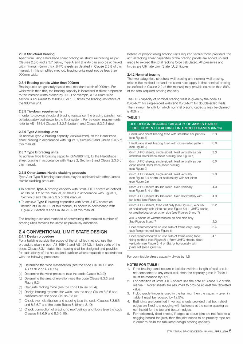
TABLE 1
For permissible stress capacity divide by 1.5
NOTES FOR TABLE 11. If the bracing panel occurs in isolation within a length of wall and is
not connected to any cross-wall, then the capacity given in Table 1must be reduced by 30%.
2. For definition of 6mm JHFC sheets see the note at Clause 1.2 of thismanual. Thicker sheets are assumed to provide at least the tabulatedvalue.
3. If JD5 grade timber is used in the framing, then the capacity given inTable 1 must be reduced by 12.5%.
4. Butt joints are permitted in vertical sheets provided that both sheetedges are fixed to a nogging with fasteners at the same spacing asnominated for the top and bottom edges.
5. For horizontally fixed sheets, if edges at a butt joint are not fixed to anogging behind the joint, then the joint needs to be properly tape-setin order to claim the tabulated design bracing capacity.
ULS DESIGN BRACING CAPACITY OF JAMES HARDIEFIBRE CEMENT CLADDING ON TIMBER FRAMES (kN/m)
HardiBrace sheet bracing fixed with standard nail pattern 3.3(see Figure 1)
HardiBrace sheet bracing fixed with close-nailed pattern 6.6(see Figure 2)
6mm JHFC sheets, single-sided, fixed vertically as per 3.3standard HardiBrace sheet bracing (see Figure 1)
6mm JHFC sheets, single-sided, fixed vertically as per 6.6close nailed HardiBrace sheet bracing(see Figure 2)
6mm JHFC sheets, single-sided, fixed vertically, 2.8(see Figure 3,4 or 5b), or horizontally with set joints(see Figure 5a)
6mm JHFC sheets double-sided, fixed vertically 4.0(see Figure 3, 4 or 5b)
6mm JHFC sheets double-sided, fixed horizontally with 4.0set joints (see Figure 5a)
6mm JHFC sheets, fixed vertically (see Figure 3, 4 or 5b) 3.2or horizontally with joints set (see Figure 5a) + (JHFC planksor weatherboards on other side (see Figures 6 and 7)
JHFC planks or weatherboards on one side onlySee Figures 6 and 7 2.0
Linea weatherboards on one side of frame only using 3.4face fixing method (see Figure 8)
Linea weatherboards on one side of frame using face 4.1fixing method (see Figure 8) + 6mm JHFC sheets, fixedvertically (see Figure 3, 4 or 5b), or horizontally withjoints set (see Figure 5a)
6 STRUCTURAL BRACING DESIGN MANUAL APRIL 2006
2.4.3 Structural BracingTable 1 provides the ULS design capacities for the James Hardie fibrecement products that may be used as designated structural bracing inthis procedure.
Where greater bracing capacities are required, anchor rods may be usedand the values in Table 4 (in Section 3 of this manual) claimed.
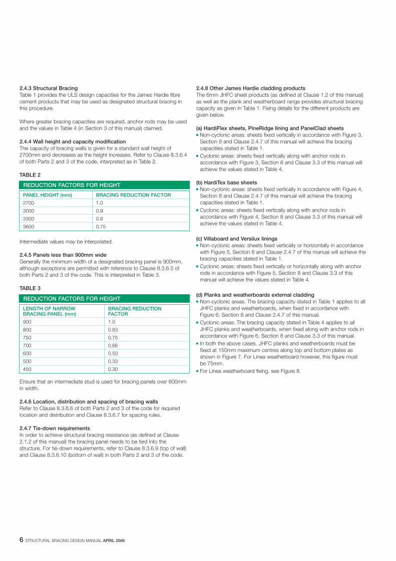
2.4.4 Wall height and capacity modificationThe capacity of bracing walls is given for a standard wall height of2700mm and decreases as the height increases. Refer to Clause 8.3.6.4of both Parts 2 and 3 of the code, interpreted as in Table 2.
TABLE 2
Intermediate values may be interpolated.
2.4.5 Panels less than 900mm wideGenerally the minimum width of a designated bracing panel is 900mm,although exceptions are permitted with reference to Clause 8.3.6.5 ofboth Parts 2 and 3 of the code. This is interpreted in Table 3.
TABLE 3
Ensure that an intermediate stud is used for bracing panels over 600mmin width.
2.4.6 Location, distribution and spacing of bracing wallsRefer to Clause 8.3.6.6 of both Parts 2 and 3 of the code for requiredlocation and distribution and Clause 8.3.6.7 for spacing rules.
2.4.7 Tie-down requirementsIn order to achieve structural bracing resistance (as defined at Clause2.1.2 of this manual) the bracing panel needs to be tied into thestructure. For tie-down requirements, refer to Clause 8.3.6.9 (top of wall)and Clause 8.3.6.10 (bottom of wall) in both Parts 2 and 3 of the code.
REDUCTION FACTORS FOR HEIGHT
PANEL HEIGHT (mm) BRACING REDUCTION FACTOR
2700 1.0
3000 0.9
3300 0.8
3600 0.75
REDUCTION FACTORS FOR HEIGHT
LENGTH OF NARROW BRACING REDUCTIONBRACING PANEL (mm) FACTOR
900 1.0
800 0.83
750 0.75
700 0.66
600 0.50
500 0.33
450 0.30
2.4.8 Other James Hardie cladding productsThe 6mm JHFC sheet products (as defined at Clause 1.2 of this manual)as well as the plank and weatherboard range provides structural bracingcapacity as given in Table 1. Fixing details for the different products aregiven below.
(a) HardiFlex sheets, PineRidge lining and PanelClad sheets� Non-cyclonic areas: sheets fixed vertically in accordance with Figure 3,
Section 8 and Clause 2.4.7 of this manual will achieve the bracingcapacities stated in Table 1.
� Cyclonic areas: sheets fixed vertically along with anchor rods inaccordance with Figure 3, Section 8 and Clause 3.3 of this manual willachieve the values stated in Table 4.
(b) HardiTex base sheets� Non-cyclonic areas: sheets fixed vertically in accordance with Figure 4,
Section 8 and Clause 2.4.7 of this manual will achieve the bracingcapacities stated in Table 1.
� Cyclonic areas: sheets fixed vertically along with anchor rods inaccordance with Figure 4, Section 8 and Clause 3.3 of this manual willachieve the values stated in Table 4.
(c) Villaboard and Versilux linings� Non-cyclonic areas: sheets fixed vertically or horizontally in accordance
with Figure 5, Section 8 and Clause 2.4.7 of this manual will achieve thebracing capacities stated in Table 1.
� Cyclonic areas: sheets fixed vertically or horizontally along with anchorrods in accordance with Figure 5, Section 8 and Clause 3.3 of thismanual will achieve the values stated in Table 4.
(d) Planks and weatherboards external cladding� Non-cyclonic areas: The bracing capacity stated in Table 1 applies to all
JHFC planks and weatherboards, when fixed in accordance with Figure 6, Section 8 and Clause 2.4.7 of this manual.
� Cyclonic areas: The bracing capacity stated in Table 4 applies to allJHFC planks and weatherboards, when fixed along with anchor rods inaccordance with Figure 6, Section 8 and Clause 3.3 of this manual.
� In both the above cases, JHFC planks and weatherboards must befixed at 150mm maximum centres along top and bottom plates asshown in Figure 7. For Linea weatherboard however, this figure must be 75mm.
� For Linea weatherboard fixing, see Figure 8.
STRUCTURAL BRACING DESIGN MANUAL APRIL 2006 7
3 BRACING FOR TIMBER FRAMING WITH ANCHOR RODS
3.1 INTRODUCTIONThis section details James Hardie fibre cement sheet cladding used forbracing with timber framing and anchor rods, specifically for winds incyclonic areas. These rods provide resistance against uplift forces andadd to the racking capacity of the wall panels.
Bracing capacities quoted in this section were proved by testing inconsultation with the James Cook Cyclone Structural Testing Station.
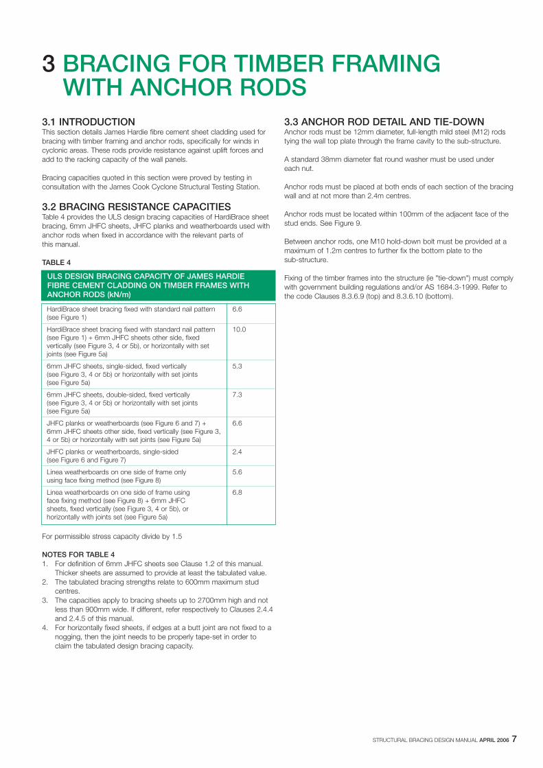
3.2 BRACING RESISTANCE CAPACITIESTable 4 provides the ULS design bracing capacities of HardiBrace sheetbracing, 6mm JHFC sheets, JHFC planks and weatherboards used withanchor rods when fixed in accordance with the relevant parts of this manual.
TABLE 4
For permissible stress capacity divide by 1.5
NOTES FOR TABLE 41. For definition of 6mm JHFC sheets see Clause 1.2 of this manual.
Thicker sheets are assumed to provide at least the tabulated value.2. The tabulated bracing strengths relate to 600mm maximum stud
centres.3. The capacities apply to bracing sheets up to 2700mm high and not
less than 900mm wide. If different, refer respectively to Clauses 2.4.4and 2.4.5 of this manual.
4. For horizontally fixed sheets, if edges at a butt joint are not fixed to anogging, then the joint needs to be properly tape-set in order toclaim the tabulated design bracing capacity.
ULS DESIGN BRACING CAPACITY OF JAMES HARDIEFIBRE CEMENT CLADDING ON TIMBER FRAMES WITHANCHOR RODS (kN/m)
HardiBrace sheet bracing fixed with standard nail pattern 6.6(see Figure 1)
HardiBrace sheet bracing fixed with standard nail pattern 10.0(see Figure 1) + 6mm JHFC sheets other side, fixedvertically (see Figure 3, 4 or 5b), or horizontally with setjoints (see Figure 5a)
6mm JHFC sheets, single-sided, fixed vertically 5.3(see Figure 3, 4 or 5b) or horizontally with set joints(see Figure 5a)
6mm JHFC sheets, double-sided, fixed vertically 7.3(see Figure 3, 4 or 5b) or horizontally with set joints(see Figure 5a)
JHFC planks or weatherboards (see Figure 6 and 7) + 6.66mm JHFC sheets other side, fixed vertically (see Figure 3,4 or 5b) or horizontally with set joints (see Figure 5a)
JHFC planks or weatherboards, single-sided 2.4(see Figure 6 and Figure 7)
Linea weatherboards on one side of frame only 5.6using face fixing method (see Figure 8)
Linea weatherboards on one side of frame using 6.8face fixing method (see Figure 8) + 6mm JHFCsheets, fixed vertically (see Figure 3, 4 or 5b), orhorizontally with joints set (see Figure 5a)
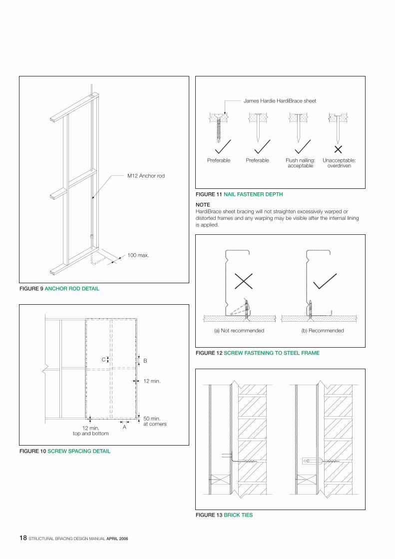
3.3 ANCHOR ROD DETAIL AND TIE-DOWNAnchor rods must be 12mm diameter, full-length mild steel (M12) rodstying the wall top plate through the frame cavity to the sub-structure.
A standard 38mm diameter flat round washer must be used under each nut.
Anchor rods must be placed at both ends of each section of the bracingwall and at not more than 2.4m centres.
Anchor rods must be located within 100mm of the adjacent face of thestud ends. See Figure 9.
Between anchor rods, one M10 hold-down bolt must be provided at amaximum of 1.2m centres to further fix the bottom plate to the sub-structure.
Fixing of the timber frames into the structure (ie "tie-down") must complywith government building regulations and/or AS 1684.3-1999. Refer tothe code Clauses 8.3.6.9 (top) and 8.3.6.10 (bottom).
8 STRUCTURAL BRACING DESIGN MANUAL APRIL 2006
4 BRACING FOR STEEL FRAMING
4.1 INTRODUCTIONExtensive testing conducted at the James Hardie R&D laboratory and atthe James Cook Cyclone Structural Testing Station has formed the basisof the information and the design capacities quoted in this section.
4.2 BRACING RESISTANCE CAPACITYTable 5 shows the bracing capacity of HardiBrace sheet bracing andother James Hardie cladding products when fixed to 0.55mm and0.75mm light gauge steel frames or 1.2mm and 1.6mm medium gauge,welded steel frames.
NOTE Only the values tested are shown in Table 5. Other values may, in certaininstances, be interpolated with experience and due diligence.
The bracing capacities are achieved by using the fixing methods outlinedin Clause 4.4 and Section 8 of this manual.
Design capacities were determined in accordance withAS 3623-1993 for 2700mm high panels unless noted otherwise.
The minimum length of a bracing wall or panel must be 900mm. The maximum wall length to which the capacities apply is 3600mm.
4.3 FRAMING CONNECTIONS0.55mm to 0.95mm light gauge steel frames:The studs need to be fixed to the top and bottom tracks by screws,rivets, bolts or mechanical crimping.
1.0mm to 1.6mm medium gauge steel frames:The connections may be welded or rivetted, noting that the designbracing capacity is 20% lower for the rivetted frames.
4.4 TIE-DOWN REQUIREMENTS0.55mm to 0.95mm light gauge steel frames:Provide M10 minimum hold-down bolts with 50 x 50 x 3mm distributionwashers at the two outside frame studs and M6 minimum hold-downbolts with 32mm diameter 2.5mm thick round washers at the interiorstuds. All bolts to be placed within 45mm of the stud.
0.95mm to 1.6mm medium gauge steel frames:Provide M12 minimum hold-down bolts with 75 x 70 x 6mm distributionwashers at 900mm centres and within 70mm of the face of studs.
NOTES FOR TABLE 51. HardiBrace sheet bracing must not be used as exposed, finished,
external cladding. 2. Bracing capacity can only be claimed for JHFC plank or
weatherboard cladding if screws pass through both planks. See Figure 6.
3. For rivetted frames of 1.2 and 1.6mm gauge, the tabulated bracingcapacities must be multiplied by a factor of 0.8.
4. For definition of 6mm JHFC sheets see Clause 1.2 of this manual.Thicker sheets are assumed to provide at least the tabulated value.
5. Butt joints are permitted in vertical sheets provided that both sheetedges are fixed to a nogging with fasteners at the same spacing asnominated for the top and bottom edges.
6. For horizontally fixed sheets: if edges at a butt joint are not fixed to anogging, then the joint needs to be properly tape-set in order toclaim the tabulated design bracing capacity.
7. For external sides of walls, 6mm Villaboard lining must be replacedby properly coated 6mm HardiFlex or 7.5mm HardiTex sheets.
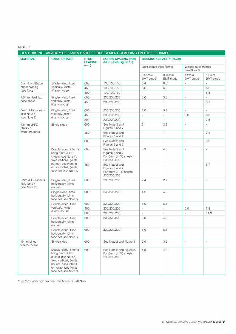
TABLE 5
* For 2700mm high frames, this figure is 5.4kN/m
STRUCTURAL BRACING DESIGN MANUAL APRIL 2006 9
ULS BRACING CAPACITY OF JAMES HARDIE FIBRE CEMENT CLADDING ON STEEL FRAMES
MATERIAL FIXING DETAILS SCREW SPACING (mm) BRACING CAPACITY (kN/m)A/B/C (See Figure 10)
Light gauge steel frames Welded steel frames(see Note 3)
0.55mm 0.75mm 1.2mm 1.6mmBMT studs BMT studs BMT studs BMT studs
600 100/100/150 5.4 6.0* - -
450 100/100/150 6.0 6.2 - 8.5
300 100/100/150 - - - 8.8
600 200/200/200 3.6 3.8 - -
450 200/200/200 - - - 5.1
600 200/200/200 3.0 3.3 - -
450 200/200/200 - - 5.8 6.0
300 200/200/200 - - - 7.5
600 See Note 2 and 2.1 2.2 - -Figures 6 and 7
450 See Note 2 and - - - 2.4Figures 6 and 7
300 See Note 2 and - - - 3.6Figures 6 and 7
600 See Note 2 and 3.9 4.0 - -Figures 6 and 7For 6mm JHFC sheets:200/200/200
450 See Note 2 and - - - 6.7Figures 6 and 7For 6mm JHFC sheets:200/200/200
600 200/200/200 2.4 2.7 - -
600 200/200/200 4.2 4.5 - -
600 200/200/200 5.6 5.7 - -
450 200/200/200 - - 6.0 7.8
300 200/200/200 - - - 11.0
600 200/200/200 3.8 4.2 - -
600 200/200/200 5.6 5.6 - -
16mm Linea 600 See Note 2 and Figure 8 3.6 3.6 - -weatherboard
600 See Note 2 and Figure 8. 4.5 4.5 - -For 6mm JHFC sheets200/200/200
STUDSPACING(mm)
5mm HardiBracesheet bracing(see Note 1)
Single-sided, fixedvertically, joints(if any) not set
7.5mm HardiTexbase sheet
Single-sided, fixedvertically, joints(if any) not set
Single-sided, fixedvertically, joints(if any) not set
6mm JHFC sheets(see Note 4)(see Note 7)
7.5mm JHFC planks or weatherboards
Single-sided
Double-sided, internallining 6mm JHFCsheets (see Note 4),fixed vertically (jointsnot set, see Note 5)or horizontally (jointstape set, see Note 6)
6mm JHFC sheets(see Note 4)(see Note 7)
Single-sided, fixedhorizontally, jointsnot set
Single-sided, fixedhorizontally, joints tape set (see Note 6)
Double-sided, fixedvertically, joints(if any) not set
Double-sided, fixedhorizontally, joints not set
Double-sided, fixedhorizontally, joints tape set (see Note 6)
Single-sided
Double-sided, internallining 6mm JHFCsheets (see Note 4),fixed vertically (jointsnot set, see Note 5)or horizontally (jointstape set, see Note 6)
10 STRUCTURAL BRACING DESIGN MANUAL APRIL 2006
5 SAFE WORKING PRACTICES
WORKING INSTRUCTIONSRefer to recommended safe working practices before starting any cuttingor machining of product.
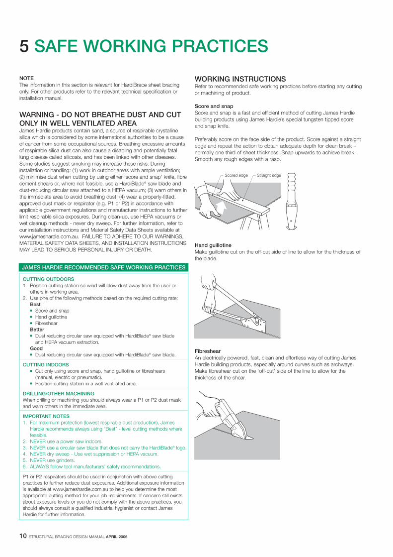
Score and snapScore and snap is a fast and efficient method of cutting James Hardiebuilding products using James Hardie’s special tungsten tipped scoreand snap knife.
Preferably score on the face side of the product. Score against a straightedge and repeat the action to obtain adequate depth for clean break –normally one third of sheet thickness. Snap upwards to achieve break.Smooth any rough edges with a rasp.
Hand guillotineMake guillotine cut on the off-cut side of line to allow for the thickness ofthe blade.
Fibreshear An electrically powered, fast, clean and effortless way of cutting JamesHardie building products, especially around curves such as archways.Make fibreshear cut on the ‘off-cut’ side of the line to allow for thethickness of the shear.
Scored edge Straight edge
NOTEThe information in this section is relevant for HardiBrace sheet bracingonly. For other products refer to the relevant technical specification orinstallation manual.
WARNING - DO NOT BREATHE DUST AND CUTONLY IN WELL VENTILATED AREAJames Hardie products contain sand, a source of respirable crystallinesilica which is considered by some international authorities to be a causeof cancer from some occupational sources. Breathing excessive amountsof respirable silica dust can also cause a disabling and potentially fatallung disease called silicosis, and has been linked with other diseases.Some studies suggest smoking may increase these risks. Duringinstallation or handling: (1) work in outdoor areas with ample ventilation; (2) minimise dust when cutting by using either 'score and snap' knife, fibrecement shears or, where not feasible, use a HardiBlade® saw blade anddust-reducing circular saw attached to a HEPA vacuum; (3) warn others inthe immediate area to avoid breathing dust; (4) wear a properly-fitted,approved dust mask or respirator (e.g. P1 or P2) in accordance withapplicable government regulations and manufacturer instructions to furtherlimit respirable silica exposures. During clean-up, use HEPA vacuums orwet cleanup methods - never dry sweep. For further information, refer toour installation instructions and Material Safety Data Sheets available atwww.jameshardie.com.au. FAILURE TO ADHERE TO OUR WARNINGS,MATERIAL SAFETY DATA SHEETS, AND INSTALLATION INSTRUCTIONSMAY LEAD TO SERIOUS PERSONAL INJURY OR DEATH.
JAMES HARDIE RECOMMENDED SAFE WORKING PRACTICES
CUTTING OUTDOORS1. Position cutting station so wind will blow dust away from the user or
others in working area.2. Use one of the following methods based on the required cutting rate:
Best� Score and snap� Hand guillotine� FibreshearBetter� Dust reducing circular saw equipped with HardiBlade® saw blade
and HEPA vacuum extraction.Good� Dust reducing circular saw equipped with HardiBlade® saw blade.
CUTTING INDOORS� Cut only using score and snap, hand guillotine or fibreshears
(manual, electric or pneumatic).� Position cutting station in a well-ventilated area.
DRILLING/OTHER MACHININGWhen drilling or machining you should always wear a P1 or P2 dust maskand warn others in the immediate area.
IMPORTANT NOTES1. For maximum protection (lowest respirable dust production), James
Hardie recommends always using “Best” - level cutting methods where feasible.
2. NEVER use a power saw indoors.3. NEVER use a circular saw blade that does not carry the HardiBlade® logo.4. NEVER dry sweep - Use wet suppression or HEPA vacuum.5. NEVER use grinders.6. ALWAYS follow tool manufacturers’ safety recommendations.
P1 or P2 respirators should be used in conjunction with above cuttingpractices to further reduce dust exposures. Additional exposure informationis available at www.jameshardie.com.au to help you determine the mostappropriate cutting method for your job requirements. If concern still existsabout exposure levels or you do not comply with the above practices, youshould always consult a qualified industrial hygienist or contact James Hardie for further information.
STRUCTURAL BRACING DESIGN MANUAL APRIL 2006 11
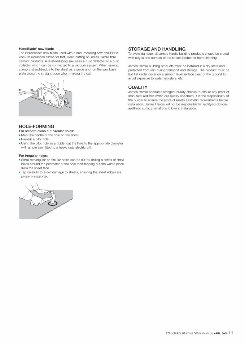
HardiBlade® saw bladeThe HardiBlade® saw blade used with a dust-reducing saw and HEPAvacuum extraction allows for fast, clean cutting of James Hardie fibrecement products. A dust-reducing saw uses a dust deflector or a dustcollector which can be connected to a vacuum system. When sawing,clamp a straight-edge to the sheet as a guide and run the saw baseplate along the straight edge when making the cut.
HOLE-FORMINGFor smooth clean cut circular holes:� Mark the centre of the hole on the sheet.� Pre-drill a pilot hole.� Using the pilot hole as a guide, cut the hole to the appropriate diameter
with a hole saw fitted to a heavy duty electric drill.
For irregular holes:� Small rectangular or circular holes can be cut by drilling a series of small
holes around the perimeter of the hole then tapping out the waste piecefrom the sheet face.
� Tap carefully to avoid damage to sheets, ensuring the sheet edges areproperly supported.
STORAGE AND HANDLINGTo avoid damage, all James Hardie building products should be storedwith edges and corners of the sheets protected from chipping.
James Hardie building products must be installed in a dry state andprotected from rain during transport and storage. The product must belaid flat under cover on a smooth level surface clear of the ground toavoid exposure to water, moisture, etc.
QUALITYJames Hardie conducts stringent quality checks to ensure any productmanufactured falls within our quality spectrum. It is the responsibility ofthe builder to ensure the product meets aesthetic requirements beforeinstallation. James Hardie will not be responsible for rectifying obviousaesthetic surface variations following installation.
12 STRUCTURAL BRACING DESIGN MANUAL APRIL 2006
6 PRODUCT INFORMATION
NOTEThe information in this section is relevant for HardiBrace sheet bracingonly. For other products refer to the relevant technical specification orinstallation manual.
6.1 GENERALHardiBrace sheet bracing, is a cellulose fibre reinforced cement buildingproduct. The basic composition is Portland cement, ground sand,cellulose fibre and water.
HardiBrace sheet bracing is manufactured to AS/NZS 2908.2 ‘Cellulose-Cement Products Part 2: Flat Sheets’ (ISO 8336 ‘Fibre Cement FlatSheets’).
HardiBrace sheet bracing is classified Type A, Category 2 in accordancewith AS/NZS 2908.2 ‘Cellulose-Cement Products’.
For Material Safety Data Sheets (MSDS) visit www.jameshardie.com.au orAsk James Hardie™ on 13 11 03.
6.2 PRODUCT MASSBased on equilibrium moisture content the approximate mass of HardiBrace sheet bracing is 6.7kg/m2.
6.3 DURABILITY6.3.1 Resistance to moisture/rottingHardiBrace sheet bracing has demonstrated resistance to permanentmoisture induced deterioration (rotting) by passing the following tests inaccordance with AS/NZS2908.2:
� Water permeability (Clause 8.2.2)� Warm water (Clause 8.2.4)� Heat rain (Clause 6.5)� Soak dry (Clause 8.2.5)
6.3.2 Resistance to fireHardiBrace sheet bracing is suitable where non-combustible materials arerequired in accordance with C1.12 of the Building Code of Australia.
HardiBrace sheet bracing has been tested by CSIRO and is classified asa Group 1 material in accordance with Specification C1.10a of the BCA.
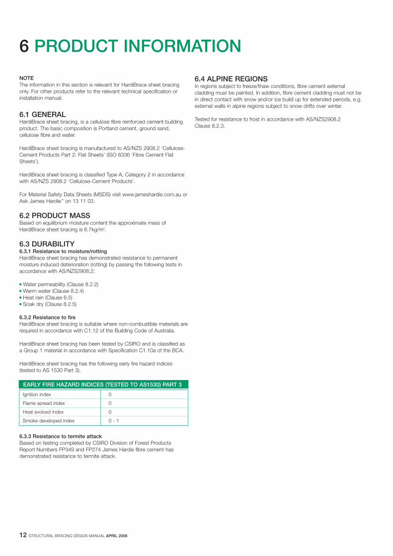
HardiBrace sheet bracing has the following early fire hazard indices(tested to AS 1530 Part 3).
6.3.3 Resistance to termite attackBased on testing completed by CSIRO Division of Forest ProductsReport Numbers FP349 and FP274 James Hardie fibre cement hasdemonstrated resistance to termite attack.
EARLY FIRE HAZARD INDICES (TESTED TO AS1530) PART 3
Ignition index 0
Flame spread index 0
Heat evolved index 0
Smoke developed index 0 - 1
6.4 ALPINE REGIONSIn regions subject to freeze/thaw conditions, fibre cement externalcladding must be painted. In addition, fibre cement cladding must not bein direct contact with snow and/or ice build up for extended periods, e.g.external walls in alpine regions subject to snow drifts over winter.
Tested for resistance to frost in accordance with AS/NZS2908.2 Clause 8.2.3.
STRUCTURAL BRACING DESIGN MANUAL APRIL 2006 13
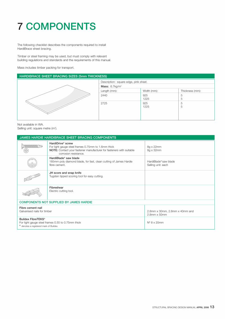
7 COMPONENTS
The following checklist describes the components required to installHardiBrace sheet bracing.
Timber or steel framing may be used, but must comply with relevantbuilding regulations and standards and the requirements of this manual.
Mass includes timber packing for transport.
Not available in WA. Selling unit: square metre (m2).
HARDIBRACE SHEET BRACING SIZES (5mm THICKNESS)
Description: square edge, pink sheet.
Mass: 6.7kg/m2
Length (mm): Width (mm): Thickness (mm):
2440 925 51225 5
2725 925 51225 5
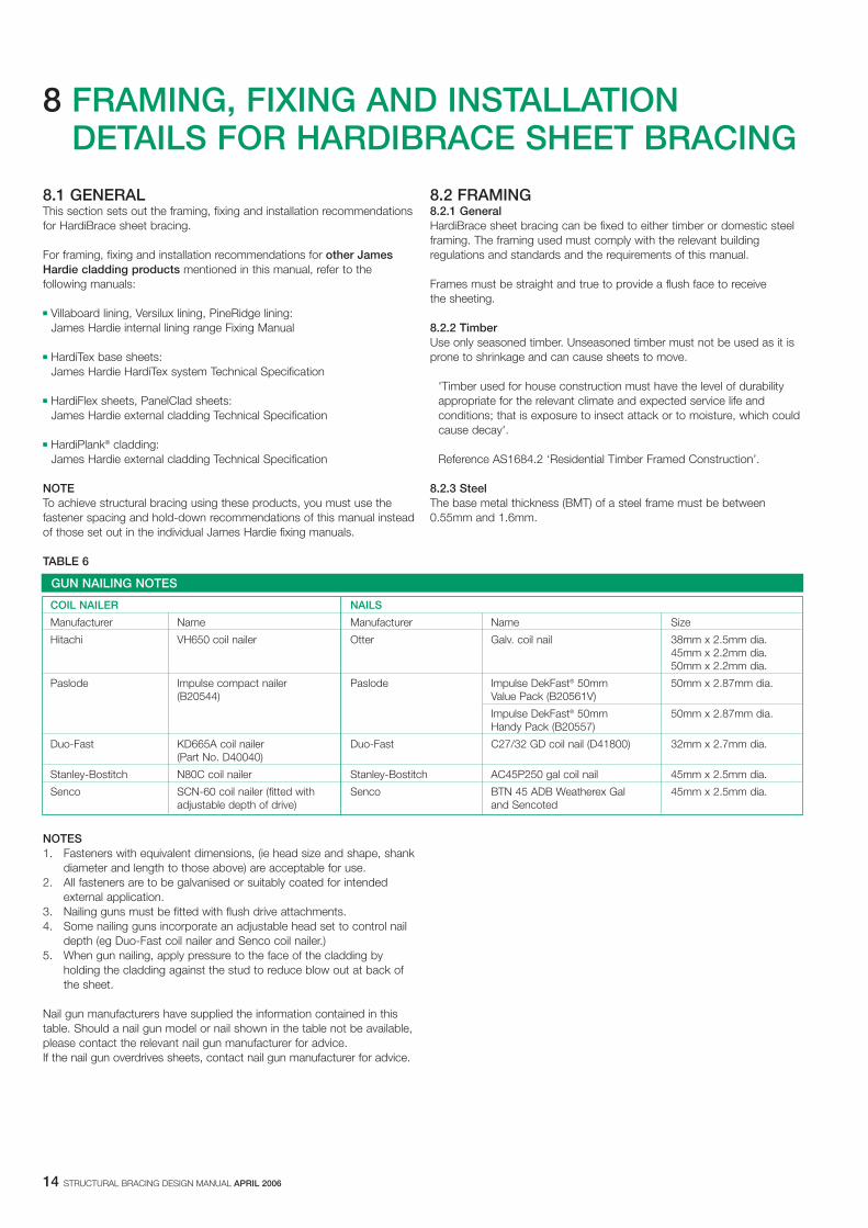
JAMES HARDIE HARDIBRACE SHEET BRACING COMPONENTS
HardiDrive® screwFor light gauge steel frames 0.75mm to 1.6mm thick 8g x 22mmNOTE: Contact your fastener manufacturer for fasteners with suitable 8g x 32mm
corrosion resistance.
HardiBlade® saw blade185mm poly diamond blade, for fast, clean cutting of James Hardie HardiBlade® saw bladefibre cement. Selling unit: each
JH score and snap knifeTugsten tipped scoring tool for easy cutting.
FibreshearElectric cutting tool.
COMPONENTS NOT SUPPLIED BY JAMES HARDIE
Fibre cement nailGalvanised nails for timber 2.8mm x 30mm, 2.8mm x 40mm and
2.8mm x 50mm
Buildex FibreTEKS®
For light gauge steel frames 0.55 to 0.75mm thick Nº 8 x 20mm® denotes a registered mark of Buildex
14 STRUCTURAL BRACING DESIGN MANUAL APRIL 2006
8 FRAMING, FIXING AND INSTALLATION DETAILS FOR HARDIBRACE SHEET BRACING
8.1 GENERALThis section sets out the framing, fixing and installation recommendationsfor HardiBrace sheet bracing.
For framing, fixing and installation recommendations for other JamesHardie cladding products mentioned in this manual, refer to thefollowing manuals:
� Villaboard lining, Versilux lining, PineRidge lining: James Hardie internal lining range Fixing Manual
� HardiTex base sheets: James Hardie HardiTex system Technical Specification
� HardiFlex sheets, PanelClad sheets: James Hardie external cladding Technical Specification
� HardiPlank® cladding: James Hardie external cladding Technical Specification
NOTETo achieve structural bracing using these products, you must use thefastener spacing and hold-down recommendations of this manual insteadof those set out in the individual James Hardie fixing manuals.
TABLE 6
NOTES1. Fasteners with equivalent dimensions, (ie head size and shape, shank
diameter and length to those above) are acceptable for use.2. All fasteners are to be galvanised or suitably coated for intended
external application.3. Nailing guns must be fitted with flush drive attachments.4. Some nailing guns incorporate an adjustable head set to control nail
depth (eg Duo-Fast coil nailer and Senco coil nailer.)5. When gun nailing, apply pressure to the face of the cladding by
holding the cladding against the stud to reduce blow out at back ofthe sheet.
Nail gun manufacturers have supplied the information contained in thistable. Should a nail gun model or nail shown in the table not be available,please contact the relevant nail gun manufacturer for advice.If the nail gun overdrives sheets, contact nail gun manufacturer for advice.
8.2 FRAMING8.2.1 General HardiBrace sheet bracing can be fixed to either timber or domestic steelframing. The framing used must comply with the relevant buildingregulations and standards and the requirements of this manual.
Frames must be straight and true to provide a flush face to receive the sheeting.
8.2.2 Timber Use only seasoned timber. Unseasoned timber must not be used as it isprone to shrinkage and can cause sheets to move.
'Timber used for house construction must have the level of durabilityappropriate for the relevant climate and expected service life andconditions; that is exposure to insect attack or to moisture, which couldcause decay'.
Reference AS1684.2 ‘Residential Timber Framed Construction’.
8.2.3 Steel The base metal thickness (BMT) of a steel frame must be between 0.55mm and 1.6mm.
GUN NAILING NOTES
COIL NAILER NAILS
Manufacturer Name Manufacturer Name Size
Hitachi VH650 coil nailer Otter Galv. coil nail 38mm x 2.5mm dia.45mm x 2.2mm dia.50mm x 2.2mm dia.
Paslode Impulse compact nailer Paslode Impulse DekFast® 50mm 50mm x 2.87mm dia.(B20544) Value Pack (B20561V)
Impulse DekFast® 50mm 50mm x 2.87mm dia.Handy Pack (B20557)
Duo-Fast KD665A coil nailer Duo-Fast C27/32 GD coil nail (D41800) 32mm x 2.7mm dia.(Part No. D40040)
Stanley-Bostitch N80C coil nailer Stanley-Bostitch AC45P250 gal coil nail 45mm x 2.5mm dia.
Senco SCN-60 coil nailer (fitted with Senco BTN 45 ADB Weatherex Gal 45mm x 2.5mm dia.adjustable depth of drive) and Sencoted
STRUCTURAL BRACING DESIGN MANUAL APRIL 2006 15
8.3 FIXING8.3.1 General You must select a fastener that is suitable for the type of frame you are using.
8.3.2 Fastener corrosion protection Fasteners must have the appropriate level of durability required for theintended project. This is of particular importance in coastal areas, areassubject to salt spray and other corrosive environments.
Fasteners must be fully compatible with all other material that they are incontact with to ensure the durability and integrity of the assembly.
Contact fastener manufacturers for more information.
NOTE Fasteners must be at least Class 3 external grade finish.
8.3.3 Fixing depth Nail sheets and boards in accordance with the nailing details shown inthis manual. Do not overdrive the nails. Proud nailing is desirable, butflush head nailing is acceptable. See Figure 11.
8.3.4 Fastening to timberUse 2.8 x 30mm hot-dipped galvanised fibre cement nails when handnailing.
HardiBrace sheet bracing can be gun-nailed onto timber frames using flathead nails. Suitable combinations are shown in Table 6.
8.3.5 Fastening to steelFor steel framing of thickness 0.55mm to 0.75mm BMT, 20mm BuildexFibreTEKS self drilling screws.
For steel framing of thickness 0.75mm to 1.6mm. Use 8g - 22mm or 8g - 32mm HardiDrive® grey external grade screws.
Fasteners should be screwed as close as possible to the stud corners toavoid deflection of the stud flange. See Figure 12.
8.3.6 Screw gun specificationUse variable speed screw guns with high torque, a maximum speed of2500rpm, fitted with a depth control attachment.
Set the depth control attachment to avoid overdriving. As the screwthread begins to pull into the steel frame, drop the revs back to bed thehead flush with the surface of the sheet.
8.4 INSTALLATION DETAILS8.4.1 GeneralHardiBrace sheet bracing can be used for cavity bracing in brick veneerconstruction or internally in locations such as behind built-in full-heightcupboards or robes.
For fastener spacings and hold-down recommendations, refer in thismanual to:
� Clause 2.2 for the simplified design method or Clause 2.3 for theconventional Limit State design method for timber framing;
� Clauses 3.2 and 3.3 for timber framing with cyclone rods;� Figure 10 and Clause 4.4 for steel framing.
NOTE HardiBrace sheet bracing must not be used as exposed, finished,external cladding.
8.4.2 Brick tiesBrick ties can be installed through HardiBrace sheet bracing. Simply referto the hole forming recommendations in Section 5. Ensure the hole is notgreater than 50mm diameter through the sheet to allow insertion of brick ties. See Figure 13.
16 STRUCTURAL BRACING DESIGN MANUAL APRIL 2006
12 min.top and bottom
150 max.top and bottom
50min.
12min.
150max.20
0 m
ax.
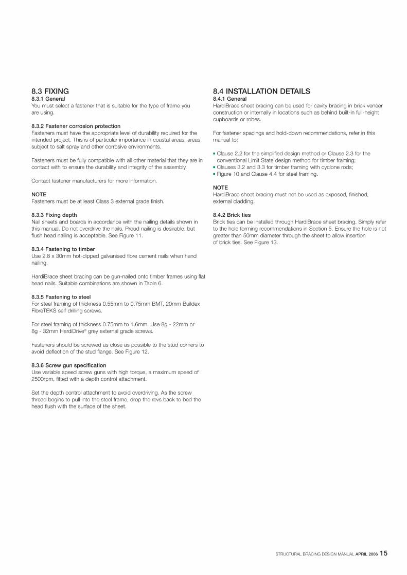
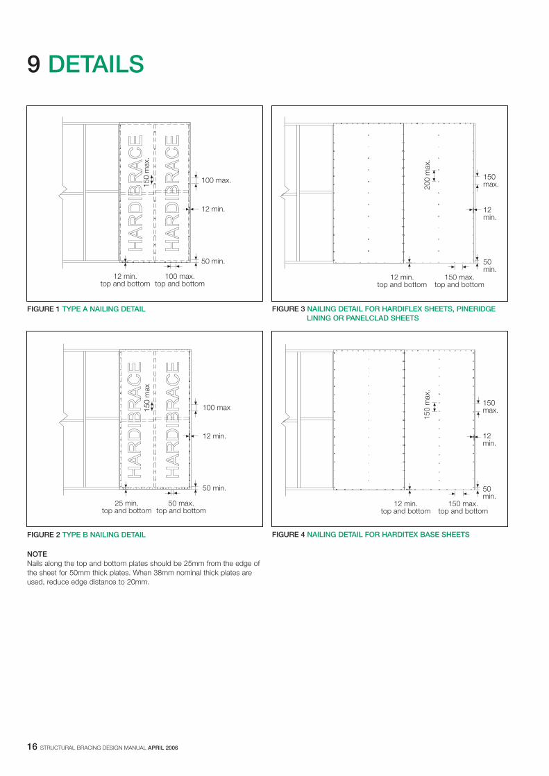
FIGURE 3 NAILING DETAIL FOR HARDIFLEX SHEETS, PINERIDGE LINING OR PANELCLAD SHEETS
12 min.top and bottom
150 max.top and bottom
50min.
12min.
150max.
150
max
.
FIGURE 4 NAILING DETAIL FOR HARDITEX BASE SHEETS
NOTE Nails along the top and bottom plates should be 25mm from the edge ofthe sheet for 50mm thick plates. When 38mm nominal thick plates areused, reduce edge distance to 20mm.
12 min.top and bottom
100 max.top and bottom
50 min.
12 min.
100 max.
150
max
.
FIGURE 1 TYPE A NAILING DETAIL
25 min.top and bottom
50 max.top and bottom
50 min.
12 min.
100 max150
max
FIGURE 2 TYPE B NAILING DETAIL
9 DETAILS
STRUCTURAL BRACING DESIGN MANUAL APRIL 2006 17
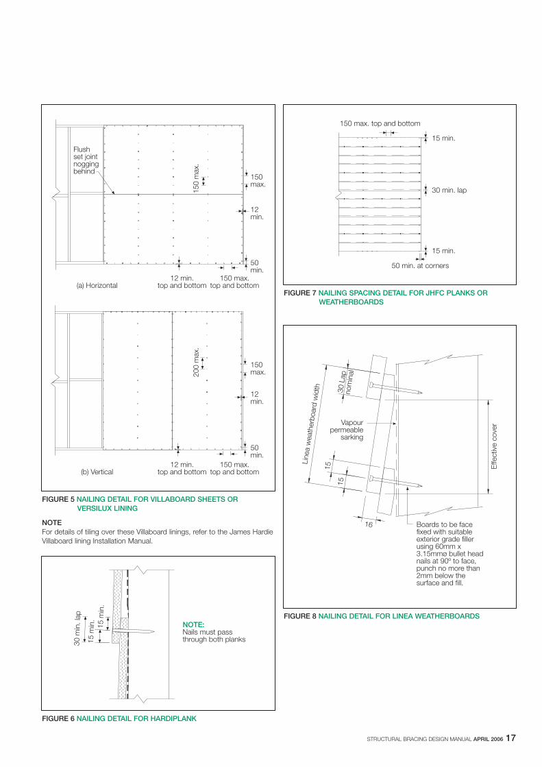
NOTEFor details of tiling over these Villaboard linings, refer to the James HardieVillaboard lining Installation Manual.
12 min.top and bottom
150 max.top and bottom
50min.
12min.
150max.
150
max
.
Flushset jointnoggingbehind
(a) Horizontal
(b) Vertical12 min.
top and bottom150 max.
top and bottom
50min.
12min.
150max.20
0 m
ax.
FIGURE 5 NAILING DETAIL FOR VILLABOARD SHEETS OR VERSILUX LINING
NOTE:Nails must passthrough both planks30
min
. lap
15 m
in.
15 m
in.
FIGURE 6 NAILING DETAIL FOR HARDIPLANK
150 max. top and bottom
50 min. at corners
15 min.
30 min. lap
15 min.
FIGURE 7 NAILING SPACING DETAIL FOR JHFC PLANKS OR WEATHERBOARDS
Boards to be facefixed with suitableexterior grade fillerusing 60mm x3.15mmø bullet headnails at 90º to face,punch no more than2mm below thesurface and fill.
16
15
15
Vapourpermeable
sarking
Line
a w
eath
erbo
ard
wid
th 30 L
ap
Effe
ctiv
e co
ver
nom
inal
FIGURE 8 NAILING DETAIL FOR LINEA WEATHERBOARDS
18 STRUCTURAL BRACING DESIGN MANUAL APRIL 2006
NOTE HardiBrace sheet bracing will not straighten excessively warped ordistorted frames and any warping may be visible after the internal lining is applied.
James Hardie HardiBrace sheet
Preferable Preferable Flush nailing:acceptable
Unacceptable:overdriven
FIGURE 11 NAIL FASTENER DEPTH
(a) Not recommended (b) Recommended
FIGURE 12 SCREW FASTENING TO STEEL FRAME
FIGURE 13 BRICK TIES
M12 Anchor rod
100 max.
FIGURE 9 ANCHOR ROD DETAIL
12 min.top and bottom
A
50 min.at corners
12 min.
BC
FIGURE 10 SCREW SPACING DETAIL
STRUCTURAL BRACING DESIGN MANUAL APRIL 2006 19
10 WARRANTY
James Hardie Australia Pty Limited ("James Hardie") warrants to the firstpurchaser of the product and the last purchaser prior to installation of theproduct for a period of 10 years from the date of purchase that theHardiBrace® sheet bracing (the "Product"), will be free from defects due todefective factory workmanship or materials and, subject to compliancewith the conditions below, will be resistant to cracking, rotting, fire anddamage from termite attacks to the extent set out in James Hardie’srelevant published literature current at the time of installation. JamesHardie warrants for a period of 12 months from the date of purchase thatthe accessories supplied by James Hardie will be free from defects due todefective factory workmanship or materials.
Nothing in this document shall exclude or modify any legal rights acustomer may have under the Trade Practices Act or otherwise whichcannot be excluded or modified at law.
CONDITIONS OF WARRANTYThe warranty is strictly subject to the following conditions:
a) James Hardie will not be liable for breach of warranty unless theclaimant provides proof of purchase and makes a written claim eitherwithin 30 days after the defect would have become reasonablyapparent or, if the defect was reasonably apparent prior toinstallation, then the claim must be made prior to installation;
b) this warranty is not transferable;
c) the Product must be installed and maintained strictly in accordancewith the relevant James Hardie literature current at the time ofinstallation and must be installed in conjunction with the componentsor products specified in the literature. To obtain copies of suchliterature contact Ask James Hardie on 13 11 03. Further, all otherproducts, including coating and jointing systems, applied to or usedin conjunction with the Product must be applied or installed andmaintained strictly in accordance with the relevant manufacturer’sinstructions and good trade practice;
d) the project must be designed and constructed in strict compliancewith all relevant provisions of the current BCA, regulations andstandards;
e) the claimant’s sole remedy for breach of warranty is (at JamesHardie’s option) that James Hardie will either supply replacementproduct, rectify the affected product or pay for the cost of thereplacement or rectification of the affected product;
f) James Hardie will not be liable for any losses or damages (whetherdirect or indirect) including property damage or personal injury,consequential loss, economic loss or loss of profits, arising incontract or negligence or howsoever arising. Without limiting theforegoing James Hardie will not be liable for any claims, damages ordefects arising from or in any way attributable to poor workmanship,poor design or detailing, settlement or structural movement and/ormovement of materials to which the Product is attached, incorrectdesign of the structure, acts of God including but not limited toearthquakes, cyclones, floods or other severe weather conditions orunusual climatic conditions, efflorescence or performance ofpaint/coatings applied to the Product, normal wear and tear, growthof mould, mildew, fungi, bacteria, or any organism on any Productsurface or Product (whether on the exposed or unexposed surfaces);
g) all warranties, conditions, liabilities and obligations other than thosespecified in this warranty are excluded to the fullest extent allowed by law;
h) if meeting a claim under this warranty involves re-coating ofProducts, there may be slight colour differences between the originaland replacement Products due to the effects of weathering andvariations in materials over time.
DISCLAIMERThe recommendations in James Hardie’s literature are based on goodbuilding practice, but are not an exhaustive statement of all relevantinformation and are subject to conditions (c), (d), (f) and (g) above.Further, as the successful performance of the relevant system dependson numerous factors outside the control of James Hardie (eg quality ofworkmanship and design) James Hardie shall not be liable for therecommendations in that literature and the performance of the relevantsystem, including its suitability for any purpose or ability to satisfy therelevant provisions of the Building Code of Australia ("BCA"), regulationsand standards.

COPYRIGHT APRIL 2006© JAMES HARDIE AUSTRALIA PTY LTD ABN 12 084 635 558TM AND ® DENOTES A TRADEMARK OR REGISTERED MARKOWNED BY JAMES HARDIE INTERNATIONAL FINANCE BV.