iq3 web enabled controller - bacnet: home · iq3 web enabled controller data sheet ta200505 issue...
TRANSCRIPT

1IQ3 Web Enabled Controller Data Sheet TA200505 Issue 3, 30/01/2009
Data Sheet
IQ3Web Enabled Controller
IQ3 Web Enabled Controller
4 5 6
27 8 9
310 11 12
4
13 14 15
516 17 18
619 20 21
722 23 24
825 26 27
928 29 30
10+ 0+ 0 + 0 + 0 + 0 + 0+ 0+ 0+ 0
1 2 3
1+ 0
0 V24 V
24 V 34 35 36
12
37 38 39
13
40 41 42
14A
31 32 33P
11
43 44 45
15
46 47 48
16100-240 V
OK RXP 0 P 0 P 0P 0 P 0 P 0
� � � � � � � � � � � � � �� � � � � �
screen earth
auxiliary output supplysupply to output power bus
263 mm (10.35”)
150
mm
(5.9
1”)
42 mm (1.65”)46 mm (1.81”)
output LEDs
input links
OK, RX Ethernet LEDs
I/O Buscover
Ethernet connector
RS232 local supervisorconnector
power supply input output channels
input channels
input LEDsUnder cover
Under frontpanel13
0 m
m (5
.12”
)
LEDs
watchdog
powerI/O bus
Description
The IQ3 controllers are Building Management System controllersthat use Ethernet and TCP/IP networking technologies; they areoptionally able to use BACnet protocol over IP. Each controllerincorporates a web server which can deliver user-specific webpages to a PC or mobile device running internet browser software.If a system is set up with the correct connections, a user withthe appropriate security codes can monitor or adjust the controllerfrom any Internet access point in the world. It is also compatiblewith the traditional IQ system protocol. The IQ3 range consistsof DIN rail mounting controllers with from zero to 16 input/outputpoints (expandable up to 128 points by adding DIN rail mountingI/O modules). This flexibility makes them suitable for a broadrange of applications. A local PC or display (SDU-xcite) can beconnected to the RS232 port.
Features
• Ethernet 10 Mbps main network with TCP/IP protocol• embedded web server with security protected monitor/control• BACnet over IP option (BTL Listed)• compatible with existing IQ system protocol• IQ3xact with 12 I/O points and IQ3xcite with 0 or 16 I/O points• IQ3xcite with 80 or 112 additional points by DIN rail I/O modules• I/O bus allows separate placement of I/O modules• flexible number of software strategy modules• RS232 local supervisor port• 100 to 240 Vac, or 24 Vac and 24 to 60 Vdc input power supply
versions• reliable I/O bus• small footprint with DIN rail mounting• battery backup, current loop Lan, or serial auxiliary board options• DHCP enabled
Physical
Diagram shows IQ3XCITE/96 or /128 (other versions may have less I/O connectors)
auxiliary board cover e.g. battery backup,current loop Lan, or serial board options
BACnet is a registered trademark of AHREA. ASHREA does not endorse, approve, or testproducts for compliance with ASHREA standards. Compliance of listed products to therequirements of the ASHREA Standard 135 is the responsibility of BACnet International (BI).BTL is the registered trademark of BI.
The BTL listing applies to/BAC option controllers
2 IQ3 Web Enabled Controller Data Sheet TA200505 Issue 3, 30/01/2009
IQ3 Data Sheet
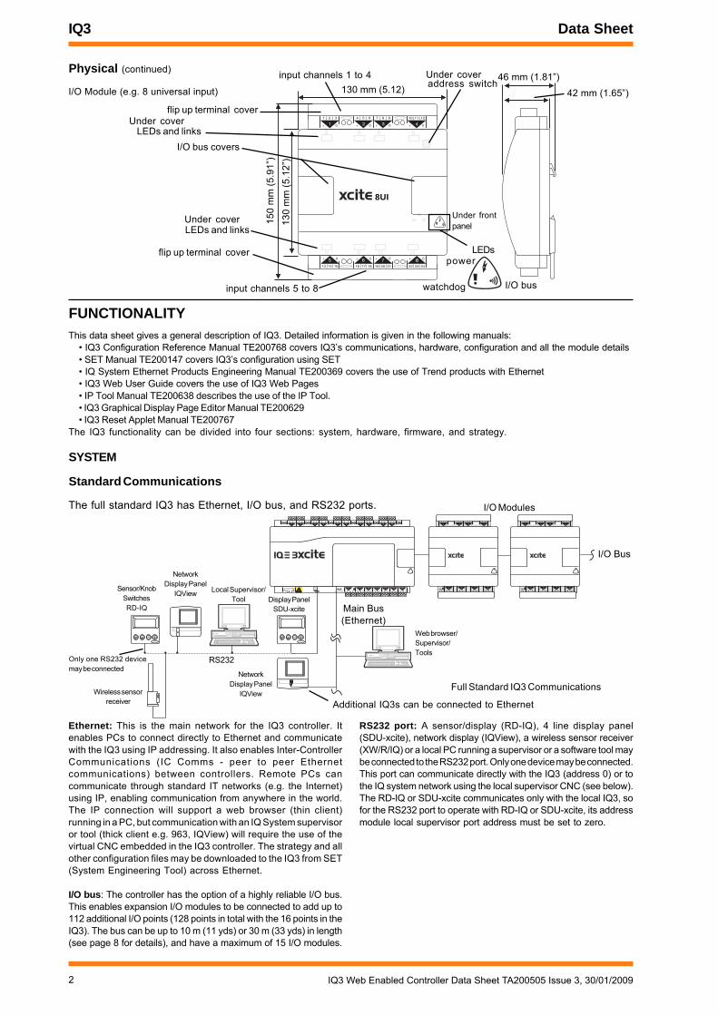
Physical (continued)
I/O Module (e.g. 8 universal input)
FUNCTIONALITYThis data sheet gives a general description of IQ3. Detailed information is given in the following manuals:
• IQ3 Configuration Reference Manual TE200768 covers IQ3’s communications, hardware, configuration and all the module details• SET Manual TE200147 covers IQ3’s configuration using SET• IQ System Ethernet Products Engineering Manual TE200369 covers the use of Trend products with Ethernet• IQ3 Web User Guide covers the use of IQ3 Web Pages• IP Tool Manual TE200638 describes the use of the IP Tool.• IQ3 Graphical Display Page Editor Manual TE200629• IQ3 Reset Applet Manual TE200767
The IQ3 functionality can be divided into four sections: system, hardware, firmware, and strategy.
SYSTEM
Standard Communications
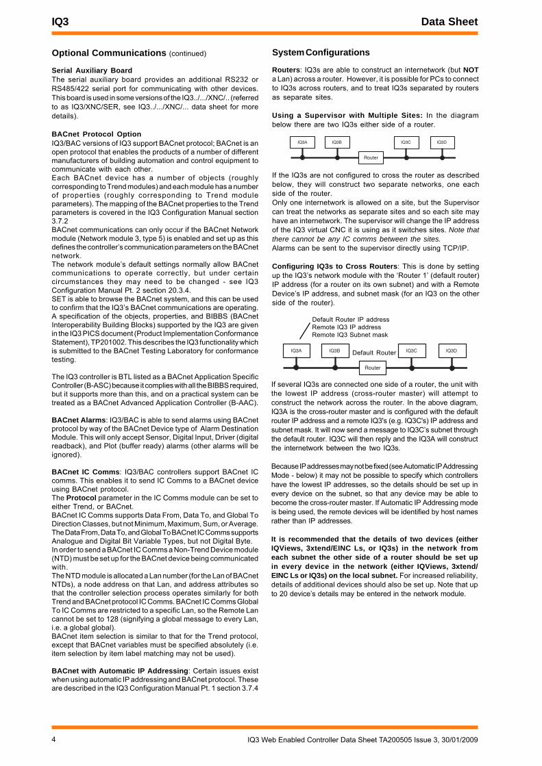
The full standard IQ3 has Ethernet, I/O bus, and RS232 ports.
Ethernet: This is the main network for the IQ3 controller. Itenables PCs to connect directly to Ethernet and communicatewith the IQ3 using IP addressing. It also enables Inter-ControllerCommunications (IC Comms - peer to peer Ethernetcommunications) between controllers. Remote PCs cancommunicate through standard IT networks (e.g. the Internet)using IP, enabling communication from anywhere in the world.The IP connection will support a web browser (thin client)running in a PC, but communication with an IQ System supervisoror tool (thick client e.g. 963, IQView) will require the use of thevirtual CNC embedded in the IQ3 controller. The strategy and allother configuration files may be downloaded to the IQ3 from SET(System Engineering Tool) across Ethernet.
I/O bus: The controller has the option of a highly reliable I/O bus.This enables expansion I/O modules to be connected to add up to112 additional I/O points (128 points in total with the 16 points in theIQ3). The bus can be up to 10 m (11 yds) or 30 m (33 yds) in length(see page 8 for details), and have a maximum of 15 I/O modules.
RS232 port: A sensor/display (RD-IQ), 4 line display panel(SDU-xcite), network display (IQView), a wireless sensor receiver(XW/R/IQ) or a local PC running a supervisor or a software tool maybe connected to the RS232 port. Only one device may be connected.This port can communicate directly with the IQ3 (address 0) or tothe IQ system network using the local supervisor CNC (see below).The RD-IQ or SDU-xcite communicates only with the local IQ3, sofor the RS232 port to operate with RD-IQ or SDU-xcite, its addressmodule local supervisor port address must be set to zero.
8+ 07+ 06+ 0
13 14 15
5+ 0
16 17 18 19 20 21 22 23 24
1 2 3
1+ 0
4 5 6
2+ 0
7 8 9
3+ 0
10 11 12
4+ 0
42 mm (1.65”)
46 mm (1.81”)130 mm (5.12)
150
mm
(5.9
1”)
LEDs
Under frontpanel
flip up terminal cover
LEDs and linksUnder cover
Under coveraddress switch
I/O bus covers
input channels 1 to 4
input channels 5 to 8
flip up terminal cover
130
mm
(5.1
2”)
Under coverLEDs and links
watchdog
power
I/O bus
4 5 6
27 8 9
310 11 12
4
13 14 15
516 17 18
619 20 21
722 23 24
825 26 27
928 29 30
10+ 0+ 0 + 0 + 0 + 0 + 0+ 0+ 0+ 0
1 2 3
1+ 0
0 V24 V
24 V 34 35 36
12
37 38 39
13
40 41 42
14A
31 32 33P
11
43 44 45
15
46 47 48
16100-240 V
OK RXP 0 P 0 P 0P 0 P 0 P 0
24 V
P 13 14 15
5P 0
16 17 18
6P 0
19 20 21
7P 0
22 23 24
8P 0
1 2 3
1+ 0
4 5 6
2+ 0
7 8 9
3+ 0
10 11 12
4+ 0
24 V
P 13 14 15
5P 0
16 17 18
6P 0
19 20 21
7P 0
22 23 24
8P 0
1 2 3
1+ 0
4 5 6
2+ 0
7 8 9
3+ 0
10 11 12
4+ 0
I/O Bus
I/O Modules
Main Bus(Ethernet)
Web browser/Supervisor/Tools
Local Supervisor/Tool Display Panel
SDU-xcite
Only one RS232 devicemay be connected
Full Standard IQ3 Communications
RS232
Additional IQ3s can be connected to Ethernet
NetworkDisplay Panel
IQView
NetworkDisplay Panel
IQView
8UI
Sensor/KnobSwitchesRD-IQ
Wireless sensorreceiver

3IQ3 Web Enabled Controller Data Sheet TA200505 Issue 3, 30/01/2009
Data Sheet IQ3
internal Lan
vCNCvINC
IQ3
CNC sCNC
WebBrowser
alarmsby
TCP/IP
Local Supervisor/Tool
RS232
TCP/IP
Supervisor/Tool
A B
C
TCP/IP
IQ3control
Standard Communications (continued)
Networks: The IQ3 will create its own internal Lan whichincludes a node for its own controller, a CNC for its local supervisorport (sCNC - if supervisor port address is set non-zero), a virtualCNC (vCNC), and a virtual INC (vINC - address 126).
4 5 64 5 6
27 8 9
310 11 12
413 14 1513 14 15
516 17 1816 17 18
619 20 2119 20 21
722 23 2422 23 24
825 26 2725 26 27
928 29 30
10+ 0+ 0 + 0 + 0 + 0 + 0+ 0+ 0+ 0
1 2 31 2 3
1+ 0+ 0
0V24V
24V 34 35 3634 35 36
12
37 38 39
13
40 41 42
14A
31 32 33P
11
43 44 4543 44 45
15
46 47 48
16100-240 V
OK RXOK RXP 0 P 0 P 0P 0 P 0 P 0
24V
P 13 14 1513 14 15
5P 0P 0
16 17 18
6P 0P 0
19 20 2119 20 21
7P 0
22 23 2422 23 24
8P 0
1 2 3
1+ 0+ 0
4 5 64 5 6
2+ 0
7 8 97 8 9
3+ 0
10 11 12
4+ 0
24V
P 13 14 1513 14 15
5P 0P 0
16 17 1816 17 18
6P 0P 0
19 20 21
7P 0P 0
22 23 24
8P 0P 0
1 2 3
1+ 0+ 0
4 5 6
2+ 0+ 0
7 8 9
3+ 0+ 0
10 11 1210 11 12
4+ 0+ 0
Ethernet:Web BrowserSupervisor,Network display
RS232:Display panel,Local supervisorNetwork display
IQ System Current Loop Lan:IQ1s, IQ2s, IQ3s,Supervisor,INC etc
I/O Bus
current loop Lan auxiliary board
If multiple IQ3s with the same Lan number are connected toEthernet, then an Ethernet Lan will form to include these IQ3s andtheir internal nodes. They must be on the same Ethernet segment,in the same subnet, and use same UDP port.The IQ3 with the lowest IP address on the Lan also assumes theINC functionality (the other vINCs disappear) and is responsiblefor maintaining the Lan across the IQ3s.
vCNC
IQ3
CNC sCNC
WebBrowser
TCP/IP
Local Supervisor/Tool
RS232
TCP/IP
Supervisor/Tool
A B
C
vCNCvINC
IQ3
CNC sCNC
Lan
IQ3control
IQ3control
shared Lan
If multiple IQ3s with different Lan numbers are connected toEthernet then their INCs will form an internetwork (along withany EINCs/3xtends on the network).Note that Trend Ethernet devices (e.g. IQ3, EINC, 3xtend/EINC L)on the same Ethernet segment must all be on the same subnet.
vCNCvINC
IQ3
CNC sCNC
WebBrowser
TCP/IP
Local Supervisor/Tool
RS232
TCP/IP
Supervisor/Tool
A B
C
vCNCvINC
IQ3
CNC sCNC
Lan
Lan
I/N
alarmsby
TCP/IP
IQ3control
IQ3control
multiple Lans
IC Comms: The IQ3s may communicate with each other andearlier IQ (and IQL) controllers using Inter ControllerCommunications (peer to peer communications). This will use IQSystem Lan/node addressing (not direct IP addressing).
Alarm Delivery: Alarms can be delivered to the local supervisorport or to a supervisor making a permanent connection to thevirtual CNC by normal IQ system comms. Alarms can be deliveredto supervisors making temporary connections to the virtual CNCusing TCP/IP by setting the supervisor’s IP address and portnumber in the alarm destination module (i.e. IP alarms). Alarmsmay also be sent by email.Note that network alarms are sent to any connected port (e.g.supervisor connected to local supervisor port, or supervisorconnected to virtual CNC).
Optional Communications
IQ System Current Loop Lan Auxiliary BoardThe optional IQ system current loop Lan auxiliary board enablesthe IQ3 to become a device on an IQ system current loop Lan.It can no longer be part of an Ethernet Lan (or internetwork).However, it will still support access using a web browser or asupervisor or tool by way of a virtual CNC, and it can still sendIP or email alarms across Ethernet. The current loop Lan auxiliaryboard is fitted in IQ3../.../LAN versions of IQ3 (henceforth referredto as IQ3/LAN).
Once another IQ (IQ1, IQ2, or IQ3) is connected to the currentloop, the two IQs form a Lan. This can then be extended onto aninternetwork in the normal way using an INC type node (e.g. INC2,LINC, 3xtend/EINC L).
vCNC
IQ3/LAN
CNC sCNC
WebBrowser
TCP/IP
Local Supervisor/Tool
RS232
TCP/IP
Supervisor/Tool
A B
C
Lan x
IQ3control
IQ IQ IQ
INC
Internetwork
INC
Lan yLan z
INC
If a 3xtend/EINC L is used instead of an INC, then the internetwork(or a segment of it) can exist on Ethernet. This would enableEthernet Lans of IQ3s to be part of the same system network asan IQ3/LAN.
4 IQ3 Web Enabled Controller Data Sheet TA200505 Issue 3, 30/01/2009
IQ3 Data Sheet
Default Router IP addressRemote IQ3 IP addressRemote IQ3 Subnet mask
IQ3A
Router
IQ3B IQ3C IQ3D
IQ3A
Router
IQ3B IQ3C IQ3D
Default Router
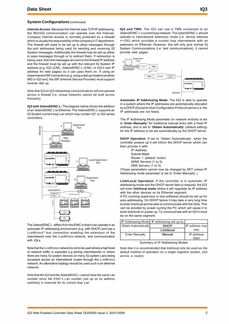
System Configurations
Routers: IQ3s are able to construct an internetwork (but NOTa Lan) across a router. However, it is possible for PCs to connectto IQ3s across routers, and to treat IQ3s separated by routersas separate sites.
Using a Supervisor with Multiple Sites: In the diagrambelow there are two IQ3s either side of a router.
If several IQ3s are connected one side of a router, the unit withthe lowest IP address (cross-router master) will attempt toconstruct the network across the router. In the above diagram,IQ3A is the cross-router master and is configured with the defaultrouter IP address and a remote IQ3's (e.g. IQ3C's) IP address andsubnet mask. It will now send a message to IQ3C’s subnet throughthe default router. IQ3C will then reply and the IQ3A will constructthe internetwork between the two IQ3s.
Because IP addresses may not be fixed (see Automatic IP AddressingMode - below) it may not be possible to specify which controllershave the lowest IP addresses, so the details should be set up inevery device on the subnet, so that any device may be able tobecome the cross-router master. If Automatic IP Addressing modeis being used, the remote devices will be identified by host namesrather than IP addresses.
It is recommended that the details of two devices (eitherIQViews, 3xtend/EINC Ls, or IQ3s) in the network fromeach subnet the other side of a router should be set upin every device in the network (either IQViews, 3xtend/EINC Ls or IQ3s) on the local subnet. For increased reliability,details of additional devices should also be set up. Note that upto 20 device’s details may be entered in the network module.
Optional Communications (continued)
Serial Auxiliary BoardThe serial auxiliary board provides an additional RS232 orRS485/422 serial port for communicating with other devices.This board is used in some versions of the IQ3../.../XNC/.. (referredto as IQ3/XNC/SER, see IQ3../.../XNC/... data sheet for moredetails).
BACnet Protocol OptionIQ3/BAC versions of IQ3 support BACnet protocol; BACnet is anopen protocol that enables the products of a number of differentmanufacturers of building automation and control equipment tocommunicate with each other.Each BACnet device has a number of objects (roughlycorresponding to Trend modules) and each module has a numberof properties (roughly corresponding to Trend moduleparameters). The mapping of the BACnet properties to the Trendparameters is covered in the IQ3 Configuration Manual section3.7.2BACnet communications can only occur if the BACnet Networkmodule (Network module 3, type 5) is enabled and set up as thisdefines the controller’s communication parameters on the BACnetnetwork.The network module’s default settings normally allow BACnetcommunications to operate correctly, but under certaincircumstances they may need to be changed - see IQ3Configuration Manual Pt. 2 section 20.3.4.SET is able to browse the BACnet system, and this can be usedto confirm that the IQ3’s BACnet communications are operating.A specification of the objects, properties, and BIBBS (BACnetInteroperability Building Blocks) supported by the IQ3 are givenin the IQ3 PICS document (Product Implementation ConformanceStatement), TP201002. This describes the IQ3 functionality whichis submitted to the BACnet Testing Laboratory for conformancetesting.
The IQ3 controller is BTL listed as a BACnet Application SpecificController (B-ASC) because it complies with all the BIBBS required,but it supports more than this, and on a practical system can betreated as a BACnet Advanced Application Controller (B-AAC).
BACnet Alarms: IQ3/BAC is able to send alarms using BACnetprotocol by way of the BACnet Device type of Alarm DestinationModule. This will only accept Sensor, Digital Input, Driver (digitalreadback), and Plot (buffer ready) alarms (other alarms will beignored).
BACnet IC Comms: IQ3/BAC controllers support BACnet ICcomms. This enables it to send IC Comms to a BACnet deviceusing BACnet protocol.The Protocol parameter in the IC Comms module can be set toeither Trend, or BACnet.BACnet IC Comms supports Data From, Data To, and Global ToDirection Classes, but not Minimum, Maximum, Sum, or Average.The Data From, Data To, and Global To BACnet IC Comms supportsAnalogue and Digital Bit Variable Types, but not Digital Byte.In order to send a BACnet IC Comms a Non-Trend Device module(NTD) must be set up for the BACnet device being communicatedwith.The NTD module is allocated a Lan number (for the Lan of BACnetNTDs), a node address on that Lan, and address attributes sothat the controller selection process operates similarly for bothTrend and BACnet protocol IC Comms. BACnet IC Comms GlobalTo IC Comms are restricted to a specific Lan, so the Remote Lancannot be set to 128 (signifying a global message to every Lan,i.e. a global global).BACnet item selection is similar to that for the Trend protocol,except that BACnet variables must be specified absolutely (i.e.item selection by item label matching may not be used).
BACnet with Automatic IP Addressing: Certain issues existwhen using automatic IP addressing and BACnet protocol. Theseare described in the IQ3 Configuration Manual Pt. 1 section 3.7.4
If the IQ3s are not configured to cross the router as describedbelow, they will construct two separate networks, one eachside of the router.Only one internetwork is allowed on a site, but the Supervisorcan treat the networks as separate sites and so each site mayhave an internetwork. The supervisor will change the IP addressof the IQ3 virtual CNC it is using as it switches sites. Note thatthere cannot be any IC comms between the sites.Alarms can be sent to the supervisor directly using TCP/IP.
Configuring IQ3s to Cross Routers: This is done by settingup the IQ3’s network module with the ‘Router 1’ (default router)IP address (for a router on its own subnet) and with a RemoteDevice’s IP address, and subnet mask (for an IQ3 on the otherside of the router).
5IQ3 Web Enabled Controller Data Sheet TA200505 Issue 3, 30/01/2009
Data Sheet IQ3
Summary of IP Addressing Modes
edoMgnisserddAPI ybputesgnisserddaPIyllacitamotuAniatbO PCHD yamsserddaPI
yravlacol/kniLyllaunaMretnE launaM sserddaPI
dexif
WebBrowser
Local Supervisor/Tool
Supervisor/Tool
Eth
ern
et A
B
C
Current Loop Lan
OK
Tx Rx
230 V1 2 3 4 5 6 83 4 5
7 9 10 1124V 24V
AC
24V
AC
24V
AC
OK
Tx Rx
230 V1 2 3 4 5 6 83 4 5
7 9 10 1124V 24V
AC
24V
AC
24V
AC
OK
Tx Rx
230 V1 2 3 4 5 6 83 4 5
7 9 10 1124V 24V
AC
24V
AC
24V
AC
3xtend/EINC L
Supervisor/ToolD
4 5 6
27 8 9
310 11 1210 11 12
413 14 15
516 17 1816 17 18
619 20 21
722 23 2422 23 24
825 26 2725 26 27
928 29 3028 29 30
10+ 0+ 0 + 0 + 0 + 0 + 0+ 0+ 0+ 0
1 2 3
1+ 0+ 0
0V24V
24V 34 35 36
12
37 38 39
13
40 41 42
14A
31 32 3331 32 33P
11
43 44 45
15
46 47 4846 47 48
16100-240 V100-240 V
OK RXP 0 P 0 P 0P 0P 0P 0 P 0 P 0
IQL
IQL
LW
ON
OR
KS
3xtend/EINC L
CNC
System Configurations (continued)
Internet Access: Because the Internet uses TCP/IP addressing,the 963/IQ3 communication can operate over the Internet.Company Internet access is normally protected by a firewallwhich is usually the responsibility of the company's IT department.The firewall will need to be set up to allow messages throughthe port addresses being used for sending and receiving IQSystem messages. Additionally the firewall may be set up eitherto pass messages through or to redirect them. If redirection isbeing used, then the messages are sent to the firewall IP addressand the firewall must be set up with the relevant IQ System IPaddress (e.g. IQ3 vCNC, 3xtend/EINC L vCNC, or IQ3’s own IPaddress for web pages) so it can pass them on. If using animpermanent ISP connection (e.g. using a dial up modem) at either963 or IQ3 end, the ISP (Internet Service Provider) must supportreverse dial up.
Note that IQ3 to IQ3 networking communications will not operateacross a firewall (i.e. virtual networks cannot be built acrossfirewalls).
IQ3 with 3xtend/EINC L: The diagram below shows the additionof an 3xtend/EINC L to Ethernet. The 3xtend/EINC L supports anIQ System current loop Lan which may contain IQ1 or IQ2 seriescontrollers.
Supervisor/Tool
Ethernet
TMN
PSTN
TMN
E
4 5 6
27 8 97 8 9
310 11 1210 11 12
413 14 1513 14 15
516 17 1816 17 18
619 20 2119 20 21
722 23 2422 23 24
825 26 27
928 29 3028 29 30
10+ 0+ 0+ 0+ 0 + 0+ 0 + 0+ 0 + 0+ 0 + 0+ 0+ 0+ 0+ 0+ 0+ 0+ 0
1 2 31 2 3
1+ 0+ 0
0V24V
24V 34 35 3634 35 36
1212
37 38 3937 38 39
1313
40 41 42
1414A
31 32 3331 32 33P
11
43 44 4543 44 45
15
46 47 4846 47 48
16100-240 V100-240 V
OK RXOK RXP 0P 0 P 0P 0 P 0P 0P 0P 0 P 0P 0 P 0P 0
3xtend/EINC L
CNCCurrent Loop
Lan
Current LoopInternetwork
The 3xtend/EINC L differs from the EINC in that it can operate in anautomatic IP addressing environment (e.g. with DHCP) and has aLONWORKS® bus connection enabling the extension of theinternetwork over the LONWORKS network, and communicationwith IQLs.
Note that the LONWORKS network is not to be used where a high levelof network traffic is expected e.g joining internetworks or wherethere are many IQ system devices on many IQ system Lans beingaccessed across an internetwork routed through the LONWORKS
network. An alternative totplogy should be used such a an ethernetnetwork.
Note that the IQ3 and the 3xtend/EINC L cannot have the same Lannumber since the EINC’s Lan number (set up on its addressswitches) is reserved for its current loop Lan.
Automatic IP Addressing Mode: The IQ3 is able to operatein a system where the IP addresses are automatically allocatedby a DHCP (Dynamic Host Configuration Protocol) server (i.e. theIP addresses are not fixed).
The IP Addressing Mode parameter (in network module) is setto ‘Enter Manually’ for traditional manual entry with a fixed IPaddress, and is set to ‘Obtain Automatically’ (default setting)for the IP address to be set automatically by the DHCP server.
DHCP Operation: If set to ‘Obtain Automatically’, when thecontroller powers up it will inform the DHCP server which canthen provide it with:
IP AddressSubnet MaskRouter 1 (default router)WINS Servers (1 to 5)DNS Servers (1 to 5)
(These parameters cannot now be changed by SET unless IPAddressing mode parameter is set to ‘Enter Manually’.)
Link/Local Operation: If the controller is in automatic IPaddressing mode and the DHCP server fails to respond, the IQ3will enter link/local mode where it will negotiate its IP addresswith the other devices on its Ethernet segment.A PC (running supervisor or tool software) should be set up forauto-addressing. On DHCP failure it may take a very long timeto enter link/local and be able to communicate with the IQ3s. Thiscan be avoided by power cycling the PC which will cause it toenter link/local on power up. To communicate with an IQ3 it mustbe on the same segment.
IQ3 and TMN: The IQ3 can use a TMN connected to an3xtend/EINC L’s current loop network. The 3xtend/EINC L shouldoperate in internetwork extension mode (i.e. device address=>100) which provides a current loop internetwork with anextension on Ethernet. However, this will only give normal IQSystem Communications (i.e. text communications), it cannotprovide web pages.
Note that it is recommended that link/local only be used as thedefault method of operation on a single segment system, (notacross a router).

6 IQ3 Web Enabled Controller Data Sheet TA200505 Issue 3, 30/01/2009
IQ3 Data Sheet
4 5 6
2+ 0
1 2 3
1+ 0
Internal screenbus
Separateearth (ground)connection
Earth (ground)link cut
ylppuScaV042)lanimon( caV42 cdV42
)lanimon(nim xam nim xam nim xam
000/eticx3QI AV6 AV51 AV5 AV11 AV4 AV8210/tcax3QI AV6 AV82 AV5 AV52 AV4 AV61610/eticx3QI AV6 AV93 AV5 AV82 AV4 AV81
821/,690/eticx3QI AV6 AV65 AV5 AV04 AV4 AV72
HARDWARE
IQ3
Box: The controller box is DIN rail mounting and must be fittedinside a cabinet. The input channel links are accessible by meansof a clear polycarbonate cover which can be unclipped using ascrewdriver. The I/O bus connector has a hinged plastic cover.The auxiliary board cover can be levered off by inserting ascrewdriver between the back of the cover and the main unit.It has a rear DIN rail clip.The digital input LEDs, the output LEDs, and the three controllerstatus LEDs can be viewed through the clear polycarbonate.
I/O Bus: This feature is only available on the expandable IQ3s(IQ3XCITE/96, /128). The IQ3xcite is connected to an adjacent I/Omodule by a rigid connector. It can be connected to a remote I/Omodule by a flexible cable. The connection is made by opening theflap, plugging in the connector, and then closing the flap over thecable. The last module on the I/O bus must be correctly terminated(see I/O Modules section). The IQ3xcite is provided with a terminator,and each I/O module is provided with a rigid interconnector.
Connectors: Other than the screen terminals, which are singlepart, two part connectors are used throughout to facilitateinstallation. The screw terminals are of a rising cage clamp typeto facilitate good connections. Each input channel has a terminalfor cable screen connection. The internal cable screen earthing(grounding) terminal bus is connected to the controller earth(ground) by a soldered link on the board. If required to segregatethe screen earth (ground) from the controller input power supplyearth (ground), it may be connected to a separate external earth(ground) by lifting the cover and cutting the screen earth (ground)link and making a connection between the internal screen busterminal and an external earth (ground).
System Configurations (continued)
Host name: Because the IP address is no longer fixed inautomatic IP addressing mode, the IQ3 a Hostname, which isfixed. When the IQ3 powers up it sends its host name to a WINS(Windows Internet Naming Service) server. If a device wishesto communicate with the IQ3 it will send the IQ3’s host name tothe WINS server which will return the associated IP address.
If a WINS server does not exist, the host name can be used overthe local segment only (i.e. not across routers).
The host name can also be used to communicate with the IQ3 ifthe IP Addressing Mode parameter (in network module) is set to‘Enter Manually’. This provides a user-friendly way of identifyingthe controller rather than remembering its IP address.
Default Host Name: If the host name has not been set up, theIQ3 will power up with a default host name which is a functionof its MAC address (‘Trend’ plus the last six digits of the MACaddress e.g. TREND_00_14_D0). The default host name willalways be operational (as well as its Hostname if it has been setup), unless the Default Hostname parameter (network module)has been set to ‘Disabled’.
Communication across the Internet: If a device (e.g.supervisor) wishes to communicate across the Internet with anIQ3 on a system with automatic IP addressing, then the firewallserver either has to be able to use the host name, or the IQ3’sIP address must be fixed.
Fixing the Controller’s Address on a DHCP controlledSystem: It is possible for the IQ3 to operate in a DHCP regimewith a fixed IP address by setting up the DHCP server so that italways gives that particular IQ3 the same IP address. Analternative is to set the IQ3 IP Addressing Mode parameter (innetwork module) to ‘Enter Manually’, and set its IP addressoutside the range of the DHCP server.
Email Server Address: Because the Email Server Address isno longer fixed on a DHCP system, it must be set up (in thenetwork module) to a host name or an Internet domain name.Thus when an email alarm is to be sent the Email Server IPAddress is resolved by either a WINS server or a DNS (DomainName System) server.
Crossing Routers if DHCP is operating: In the DHCP regime,if the internetwork is to cross a router(s), the Remote Devices(1 to 20) IP addresses should be set up as host names. This willenable the IP addresses to be obtained from the WINS servers.
Note that if any communication using a host name crosses arouter(s), then a WINS server address must be set up.
Servers: If the IQ3’s IP address settings are to be supplied bya DHCP server, the server must be installed on the same segmentas the IQ3. On a multi-segment system a single DHCP server maybe use providing it has a connection to each segment, i.e. multipleconnections.
The server must be capable of downloading either or both (asappropriate, see below) the WINS server address, and the DNSserver address.
If host names are being used for IP addressing across a router,then a WINS server must be installed somewhere on the system.If email alarms are being sent, and the email server address isidentified by Internet domain name, then a DNS server must beinstalled somewhere on the system.
Service Button: The IQ3 can be restored to defaults by holdingdown the service button for greater than 2 s (but less than 15 s)as the IQ3 is powered up.
Power Supply: The IQ3 can be supplied in two input power supplyversions./100-240 :100 to 240 Vac at 50 or 60 Hz. Power requirement
is 56 VA maximum.Note that a switch or circuit breaker (240 Vac, 3 A) must beincluded in the supply to the unit and in close proximity to it, andit must be clearly marked as the disconnecting device for the unit.
/24 :24 Vac at 50 or 60 Hz, 24 to 60 Vdc (36 Vdcmaximum for /UL versions). Power requirement is40 VA maximum.
A summary of the minimum and maximum power requirementsis given below:
The minimum power is for the core electronics without any I/Oauxiliary power or additional I/O modules. The maximum powerfor the IQ3xcite/000 includes core electronics and maximumauxiliary supply consumption, for the IQ3xact/012 andIQ3xcite/016 it also includes maximum I/O consumption; themaximum for the IQ3xcite/96 and /128 includes core electronics,maximum I/O consumption, and maximum auxiliary supply of700 mA (which includes power to the I/O bus).
Servicebutton
7IQ3 Web Enabled Controller Data Sheet TA200505 Issue 3, 30/01/2009
Data Sheet IQ3
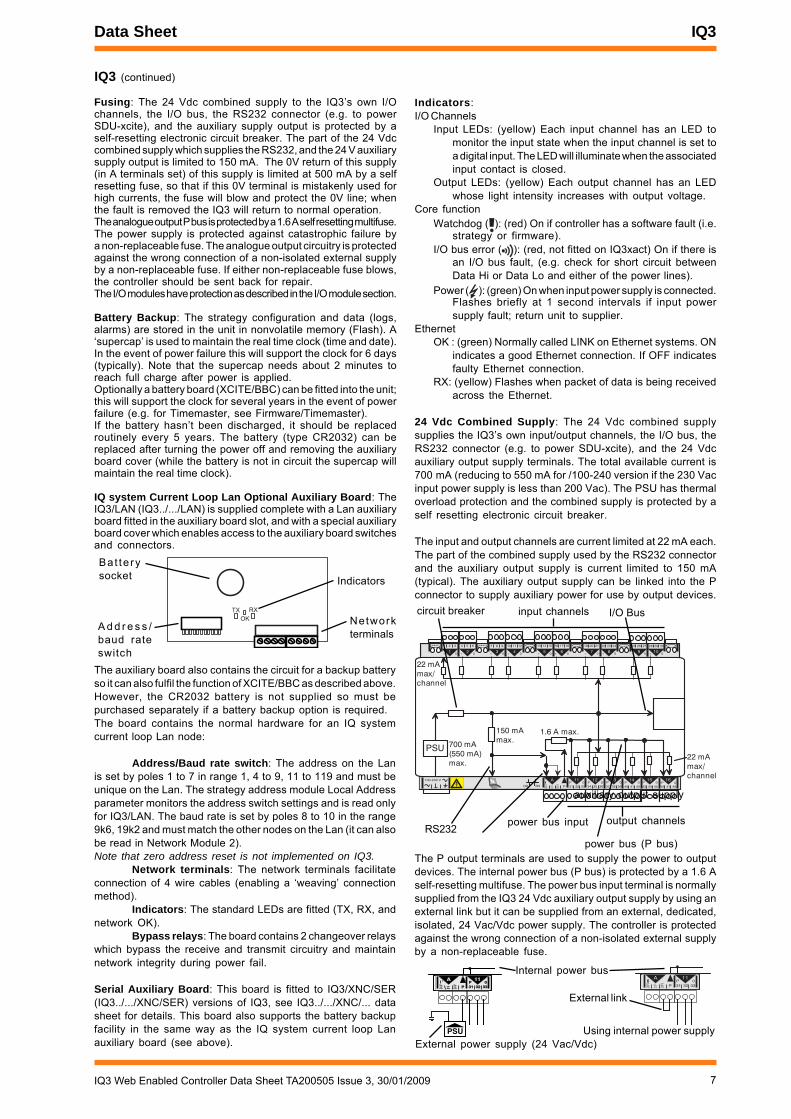
The P output terminals are used to supply the power to outputdevices. The internal power bus (P bus) is protected by a 1.6 Aself-resetting multifuse. The power bus input terminal is normallysupplied from the IQ3 24 Vdc auxiliary output supply by using anexternal link but it can be supplied from an external, dedicated,isolated, 24 Vac/Vdc power supply. The controller is protectedagainst the wrong connection of a non-isolated external supplyby a non-replaceable fuse.
A
PSU
0V24V
24V
A
31 32 33P
11P 0
A
0 V24 V
24 V
A
31 32 33P
11P 0
Internal power bus
External power supply (24 Vac/Vdc)
External link
Using internal power supply
Indicators:I/O Channels
Input LEDs: (yellow) Each input channel has an LED tomonitor the input state when the input channel is set toa digital input. The LED will illuminate when the associatedinput contact is closed.
Output LEDs: (yellow) Each output channel has an LEDwhose light intensity increases with output voltage.
Core functionWatchdog ( ): (red) On if controller has a software fault (i.e.
strategy or firmware).I/O bus error ( ): (red, not fitted on IQ3xact) On if there is
an I/O bus fault, (e.g. check for short circuit betweenData Hi or Data Lo and either of the power lines).
Power ( ): (green) On when input power supply is connected.Flashes briefly at 1 second intervals if input powersupply fault; return unit to supplier.
EthernetOK : (green) Normally called LINK on Ethernet systems. ON
indicates a good Ethernet connection. If OFF indicatesfaulty Ethernet connection.
RX: (yellow) Flashes when packet of data is being receivedacross the Ethernet.
24 Vdc Combined Supply: The 24 Vdc combined supplysupplies the IQ3’s own input/output channels, the I/O bus, theRS232 connector (e.g. to power SDU-xcite), and the 24 Vdcauxiliary output supply terminals. The total available current is700 mA (reducing to 550 mA for /100-240 version if the 230 Vacinput power supply is less than 200 Vac). The PSU has thermaloverload protection and the combined supply is protected by aself resetting electronic circuit breaker.
The input and output channels are current limited at 22 mA each.The part of the combined supply used by the RS232 connectorand the auxiliary output supply is current limited to 150 mA(typical). The auxiliary output supply can be linked into the Pconnector to supply auxiliary power for use by output devices.
A
0 V24 V
24 V 34 35 36
12
37 38 39
13
40 41 42
14A
31 32 33P
11
43 44 45
15
46 47 48
16100-240 V
OK RXP 0 P 0 P 0P 0 P 0 P 0
4 5 6
27 8 9
310 11 12
4
13 14 15
516 17 18
619 20 21
722 23 24
825 26 27
928 29 30
10+ 0+ 0 + 0 + 0 + 0 + 0+ 0+ 0+ 0
1 2 3
1+ 0
PSU 700 mA(550 mA)max.
150 mAmax.
1.6 A max.
22 mAmax/channel
22 mAmax/channel
input channels I/O Bus
RS232
auxiliary output supply
power bus input output channels
power bus (P bus)
circuit breaker
IQ3 (continued)
Fusing: The 24 Vdc combined supply to the IQ3’s own I/Ochannels, the I/O bus, the RS232 connector (e.g. to powerSDU-xcite), and the auxiliary supply output is protected by aself-resetting electronic circuit breaker. The part of the 24 Vdccombined supply which supplies the RS232, and the 24 V auxiliarysupply output is limited to 150 mA. The 0V return of this supply(in A terminals set) of this supply is limited at 500 mA by a selfresetting fuse, so that if this 0V terminal is mistakenly used forhigh currents, the fuse will blow and protect the 0V line; whenthe fault is removed the IQ3 will return to normal operation.The analogue output P bus is protected by a 1.6 A self resetting multifuse.The power supply is protected against catastrophic failure bya non-replaceable fuse. The analogue output circuitry is protectedagainst the wrong connection of a non-isolated external supplyby a non-replaceable fuse. If either non-replaceable fuse blows,the controller should be sent back for repair.The I/O modules have protection as described in the I/O module section.
Battery Backup: The strategy configuration and data (logs,alarms) are stored in the unit in nonvolatile memory (Flash). A‘supercap’ is used to maintain the real time clock (time and date).In the event of power failure this will support the clock for 6 days(typically). Note that the supercap needs about 2 minutes toreach full charge after power is applied.Optionally a battery board (XCITE/BBC) can be fitted into the unit;this will support the clock for several years in the event of powerfailure (e.g. for Timemaster, see Firmware/Timemaster).If the battery hasn’t been discharged, it should be replacedroutinely every 5 years. The battery (type CR2032) can bereplaced after turning the power off and removing the auxiliaryboard cover (while the battery is not in circuit the supercap willmaintain the real time clock).
IQ system Current Loop Lan Optional Auxiliary Board: TheIQ3/LAN (IQ3../.../LAN) is supplied complete with a Lan auxiliaryboard fitted in the auxiliary board slot, and with a special auxiliaryboard cover which enables access to the auxiliary board switchesand connectors.
TX RX
OK
Bat te rysocket
A d d r e s s /baud rateswitch
Indicators
Networkterminals
The auxiliary board also contains the circuit for a backup batteryso it can also fulfil the function of XCITE/BBC as described above.However, the CR2032 battery is not supplied so must bepurchased separately if a battery backup option is required.The board contains the normal hardware for an IQ systemcurrent loop Lan node:
Address/Baud rate switch: The address on the Lanis set by poles 1 to 7 in range 1, 4 to 9, 11 to 119 and must beunique on the Lan. The strategy address module Local Addressparameter monitors the address switch settings and is read onlyfor IQ3/LAN. The baud rate is set by poles 8 to 10 in the range9k6, 19k2 and must match the other nodes on the Lan (it can alsobe read in Network Module 2).Note that zero address reset is not implemented on IQ3.
Network terminals: The network terminals facilitateconnection of 4 wire cables (enabling a ‘weaving’ connectionmethod).
Indicators: The standard LEDs are fitted (TX, RX, andnetwork OK).
Bypass relays: The board contains 2 changeover relayswhich bypass the receive and transmit circuitry and maintainnetwork integrity during power fail.
Serial Auxiliary Board: This board is fitted to IQ3/XNC/SER(IQ3../.../XNC/SER) versions of IQ3, see IQ3../.../XNC/... datasheet for details. This board also supports the battery backupfacility in the same way as the IQ system current loop Lanauxiliary board (see above).
8 IQ3 Web Enabled Controller Data Sheet TA200505 Issue 3, 30/01/2009
IQ3 Data Sheet
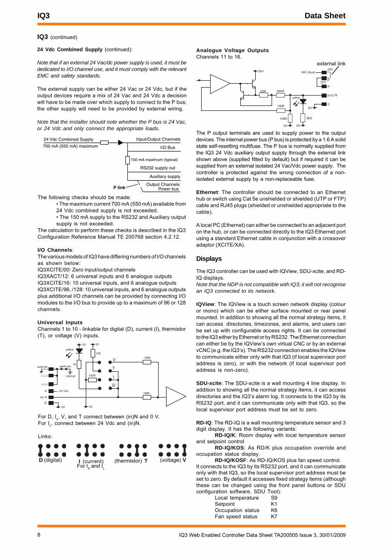
Analogue Voltage OutputsChannels 11 to 16.
IQ3 (continued)
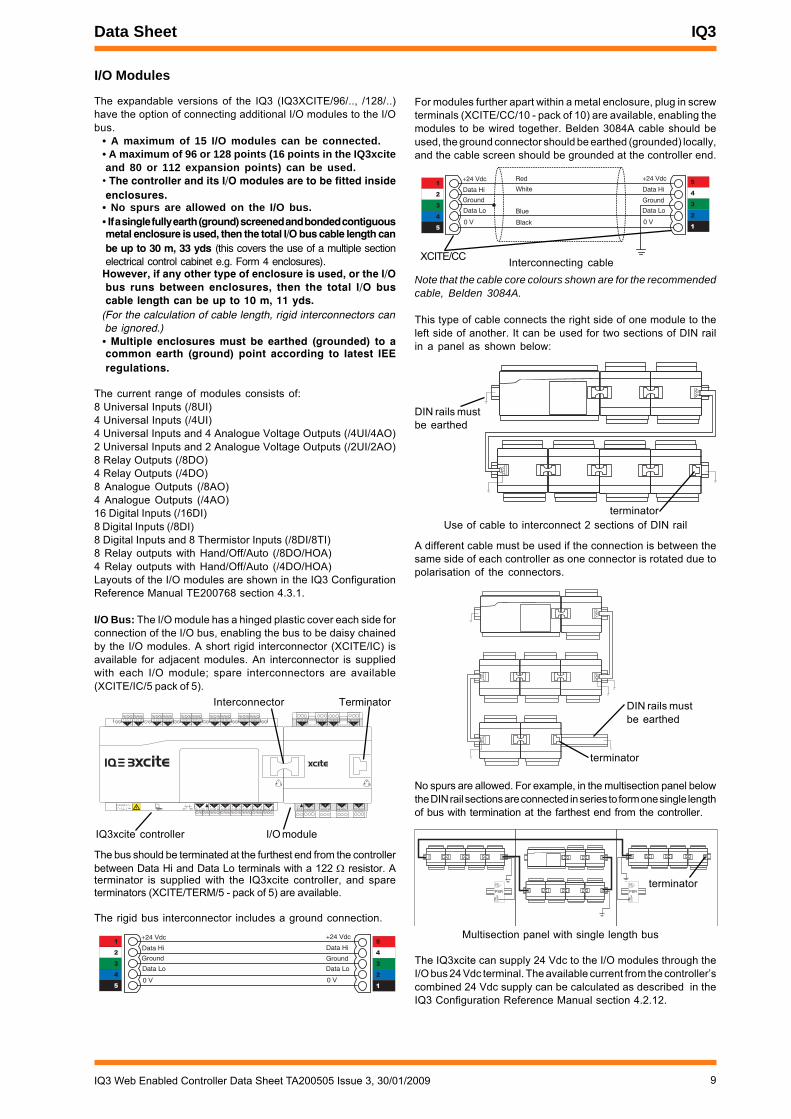
24 Vdc Combined Supply (continued):
Note that if an external 24 Vac/dc power supply is used, it must bededicated to I/O channel use, and it must comply with the relevantEMC and safety standards.
The external supply can be either 24 Vac or 24 Vdc, but if theoutput devices require a mix of 24 Vac and 24 Vdc a decisionwill have to be made over which supply to connect to the P bus;the other supply will need to be provided by external wiring.
Note that the installer should note whether the P bus is 24 Vac,or 24 Vdc and only connect the appropriate loads.
24 Vdc Combined Supply
I/O Bus
Auxiliary supply
RS232 supply out
Output Channels
150 mA maximum (typical)
700 mA (550 mA) maximum
Input/Output Channels
Power busP link
The following checks should be made:• The maximum current 700 mA (550 mA) available from24 Vdc combined supply is not exceeded.• The 150 mA supply to the RS232 and Auxiliary outputsupply is not exceeded.
The calculation to perform these checks is described in the IQ3Configuration Reference Manual TE 200768 section 4.2.12.
I/O Channels:The various models of IQ3 have differing numbers of I/O channelsas shown below:IQ3XCITE/00: Zero input/output channelsIQ3XACT/12: 6 universal inputs and 6 analogue outputsIQ3XCITE/16: 10 universal inputs, and 6 analogue outputsIQ3XCITE/96, /128: 10 universal inputs, and 6 analogue outputsplus additional I/O channels can be provided by connecting I/Omodules to the I/O bus to provide up to a maximum of 96 or 128channels.
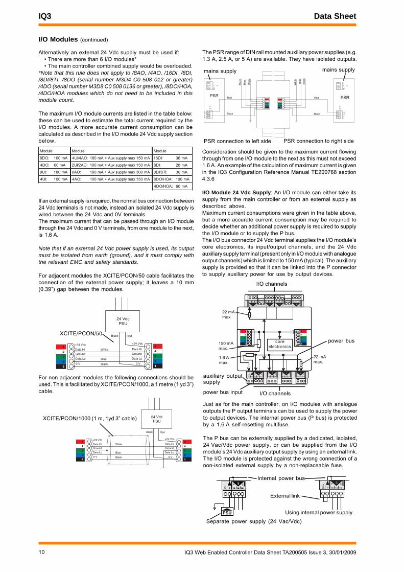
Universal InputsChannels 1 to 10 - linkable for digital (D), current (I), thermistor(T), or voltage (V) inputs.
5V5V
yellow
V
0V
(in) N
1K
10K
108K
240R
100K
T
I
D+
0
+24 Vdc
0V
internal
earth linkexternal
D (digital) I (current) (thermistor) T (voltage) VFor IX and IL
24V
0V
(out) N
0100K
22R 330R
0V
100K
24V (Aux)
P
P
24V
yellow
0V
3K3
external link
For D, Ix, V, and T connect between (in)N and 0 V.For IL, connect between 24 Vdc and (in)N.
Links:
The P output terminals are used to supply power to the outputdevices. The internal power bus (P bus) is protected by a 1.6 A solidstate self-resetting multifuse. The P bus is normally supplied fromthe IQ3 24 Vdc auxiliary output supply through the external linkshown above (supplied fitted by default) but if required it can besupplied from an external isolated 24 Vac/Vdc power supply. Thecontroller is protected against the wrong connection of a non-isolated external supply by a non-replaceable fuse.
Ethernet: The controller should be connected to an Ethernethub or switch using Cat 5e unshielded or shielded (UTP or FTP)cable and RJ45 plugs (shielded or unshielded appropriate to thecable).
A local PC (Ethernet) can either be connected to an adjacent porton the hub, or can be connected directly to the IQ3 Ethernet portusing a standard Ethernet cable in conjunction with a crossoveradaptor (XCITE/XA).
Displays
The IQ3 controller can be used with IQView, SDU-xcite, and RD-IQ displays.Note that the NDP is not compatible with IQ3; it will not recognisean IQ3 connected to its network.
IQView: The IQView is a touch screen network display (colouror mono) which can be either surface mounted or rear panelmounted. In addition to showing all the normal strategy items, itcan access directories, timezones, and alarms, and users canbe set up with configurable access rights. It can be connectedto the IQ3 either by Ethernet or by RS232. The Ethernet connectioncan either be by the IQView’s own virtual CNC or by an externalvCNC (e.g. the IQ3’s). The RS232 connection enables the IQViewto communicate either only with that IQ3 (if local supervisor portaddress is zero), or with the network (if local supervisor portaddress is non-zero).
SDU-xcite: The SDU-xcite is a wall mounting 4 line display. Inaddition to showing all the normal strategy items, it can accessdirectories and the IQ3’s alarm log. It connects to the IQ3 by itsRS232 port, and it can communicate only with that IQ3, so thelocal supervisor port address must be set to zero.
RD-IQ: The RD-IQ is a wall mounting temperature sensor and 3digit display. It has the following variants:
RD-IQ/K: Room display with local temperature sensorand setpoint control
RD-IQ/KOS: As RD/K plus occupation override andoccupation status display.
RD-IQ/KOSF: As RD-IQ/KOS plus fan speed control.It connects to the IQ3 by its RS232 port, and it can communicateonly with that IQ3, so the local supervisor port address must beset to zero. By default it accesses fixed strategy items (althoughthese can be changed using the front panel buttons or SDUconfiguration software, SDU Tool):
Local temperature S9Setpoint K1Occupation status K6Fan speed status K7
9IQ3 Web Enabled Controller Data Sheet TA200505 Issue 3, 30/01/2009
Data Sheet IQ3
For modules further apart within a metal enclosure, plug in screwterminals (XCITE/CC/10 - pack of 10) are available, enabling themodules to be wired together. Belden 3084A cable should beused, the ground connector should be earthed (grounded) locally,and the cable screen should be grounded at the controller end.
L+L+L-L-
L
N
DC
ADJ.
IN
PSRL+L+L-L-
L
N
DC
ADJ.
IN
PSR
terminator
Multisection panel with single length bus
The bus should be terminated at the furthest end from the controllerbetween Data Hi and Data Lo terminals with a 122 resistor. Aterminator is supplied with the IQ3xcite controller, and spareterminators (XCITE/TERM/5 - pack of 5) are available.
The rigid bus interconnector includes a ground connection.
A different cable must be used if the connection is between thesame side of each controller as one connector is rotated due topolarisation of the connectors.
terminator
DIN rails mustbe earthed
terminatorUse of cable to interconnect 2 sections of DIN rail
DIN rails mustbe earthed
I/O Modules
The expandable versions of the IQ3 (IQ3XCITE/96/.., /128/..)have the option of connecting additional I/O modules to the I/Obus.
• A maximum of 15 I/O modules can be connected.• A maximum of 96 or 128 points (16 points in the IQ3xciteand 80 or 112 expansion points) can be used.
• The controller and its I/O modules are to be fitted insideenclosures.
• No spurs are allowed on the I/O bus.• If a single fully earth (ground) screened and bonded contiguousmetal enclosure is used, then the total I/O bus cable length canbe up to 30 m, 33 yds (this covers the use of a multiple sectionelectrical control cabinet e.g. Form 4 enclosures).
However, if any other type of enclosure is used, or the I/Obus runs between enclosures, then the total I/O buscable length can be up to 10 m, 11 yds.
(For the calculation of cable length, rigid interconnectors canbe ignored.)
• Multiple enclosures must be earthed (grounded) to acommon earth (ground) point according to latest IEEregulations.
The current range of modules consists of:8 Universal Inputs (/8UI)4 Universal Inputs (/4UI)4 Universal Inputs and 4 Analogue Voltage Outputs (/4UI/4AO)2 Universal Inputs and 2 Analogue Voltage Outputs (/2UI/2AO)8 Relay Outputs (/8DO)4 Relay Outputs (/4DO)8 Analogue Outputs (/8AO)4 Analogue Outputs (/4AO)16 Digital Inputs (/16DI)8 Digital Inputs (/8DI)8 Digital Inputs and 8 Thermistor Inputs (/8DI/8TI)8 Relay outputs with Hand/Off/Auto (/8DO/HOA)4 Relay outputs with Hand/Off/Auto (/4DO/HOA)Layouts of the I/O modules are shown in the IQ3 ConfigurationReference Manual TE200768 section 4.3.1.
I/O Bus: The I/O module has a hinged plastic cover each side forconnection of the I/O bus, enabling the bus to be daisy chainedby the I/O modules. A short rigid interconnector (XCITE/IC) isavailable for adjacent modules. An interconnector is suppliedwith each I/O module; spare interconnectors are available(XCITE/IC/5 pack of 5).
+24 Vdc
0 V
Data Hi
Data Lo
+24 Vdc
0 V
Data Hi
Data Lo
Ground Ground
�
�
�
�
�
�
�
�
�
�
+24 Vdc
0 V
Data Hi
Data Lo
+24 Vdc
0 V
Data Hi
Data Lo
Ground Ground
Red
White
Blue
Black
�
�
�
�
�
�
�
�
�
�
XCITE/CC Interconnecting cable
No spurs are allowed. For example, in the multisection panel belowthe DIN rail sections are connected in series to form one single lengthof bus with termination at the farthest end from the controller.
4 5 6
27 8 9
310 11 12
413 14 15
516 17 18
619 20 21
722 23 24
825 26 27
928 29 30
10+ 0+ 0 + 0 + 0 + 0 + 0+ 0+ 0+ 0
1 2 3
1+ 0
0 V24 V
24 V 34 35 36
12
37 38 39
13
40 41 42
14A
31 32 33P
11
43 44 45
15
46 47 48
16100-240 V
OK RXP 0 P 0 P 0P 0 P 0 P 0
24 V
P 13 14 15
5P 0
16 17 18
6P 0
19 20 21
7P 0
22 23 24
8P 0
1 2 3
1+ 0
4 5 6
2+ 0
7 8 9
3+ 0
10 11 12
4+ 0
IQ3xcite controller I/O module
Interconnector Terminator
Note that the cable core colours shown are for the recommendedcable, Belden 3084A.
This type of cable connects the right side of one module to theleft side of another. It can be used for two sections of DIN railin a panel as shown below:
The IQ3xcite can supply 24 Vdc to the I/O modules through theI/O bus 24 Vdc terminal. The available current from the controller’scombined 24 Vdc supply can be calculated as described in theIQ3 Configuration Reference Manual section 4.2.12.
10 IQ3 Web Enabled Controller Data Sheet TA200505 Issue 3, 30/01/2009
IQ3 Data Sheet
PSU
24V
P 13 14 1513 14 15
5P 0
24 V
P 13 14 15
5P 0
Internal power bus
Separate power supply (24 Vac/Vdc)
External link
Using internal power supply
150 mAmax.
1.6 A max.
22 mAmax
22 mAmax.
1 2 3
1+ 0
4 5 6
2+ 0
7 8 9
3+ 0
10 11 12
4+ 0
core electronics
24 V
P 13 14 15
5P 0
16 17 18
6P 0
19 20 21
7P 0
22 23 24
8P 0
�
�
�
�
�
�
�
�
�
�
I/O channels
auxiliary outputsupply
power bus input I/O channels
power bus
I/O Modules (continued)
Alternatively an external 24 Vdc supply must be used if:• There are more than 6 I/O modules*• The main controller combined supply would be overloaded.
*Note that this rule does not apply to /8AO, /4AO, /16DI, /8DI,/8DI/8TI, /8DO (serial number M3D4 C0 508 012 or greater)/4DO (serial number M3D8 C0 508 0136 or greater), /8DO/HOA,/4DO/HOA modules which do not need to be included in thismodule count.
The maximum I/O module currents are listed in the table below:these can be used to estimate the total current required by theI/O modules. A more accurate current consumption can becalculated as described in the I/O module 24 Vdc supply sectionbelow.
Just as for the main controller, on I/O modules with analogueoutputs the P output terminals can be used to supply the powerto output devices. The internal power bus (P bus) is protectedby a 1.6 A self-resetting multifuse.
The P bus can be externally supplied by a dedicated, isolated,24 Vac/Vdc power supply, or can be supplied from the I/Omodule’s 24 Vdc auxiliary output supply by using an external link.The I/O module is protected against the wrong connection of anon-isolated external supply by a non-replaceable fuse.
L+L+L-L-
L
N
DC
ADJ.
IN
Black
Red
Bla
ck
Whi
te
Blu
e
PSR�
�
�
�
�
L+L+L-L-
L
N
DC
ADJ.
IN
Black
Red
Bla
ck
Whi
te
Blu
e
PSR�
�
�
�
�
PSR connection to left side PSR connection to right side
mains supply mains supply
eludoM
:OD8 Am001
:OD4 Am06
:IU8 Am081
:IU4 Am001
eludoM
:OA4/IU4 Am051xamylppusxuA+Am081
:OA2/IU2 Am051xamylppusxuA+Am001
:OA8 Am003xamylppusxuA+Am081
:OA4 Am051xamylppusxuA+Am001
eludoM
:ID61 Am63
:ID8 Am82
:IT8/ID8 Am03
:AOH/OD8 Am001
:AOH/OD4 Am06
24 VdcPSU
+24 Vdc
0 V
Data Hi
Data Lo
+24 Vdc
0 V
Data Hi
Data Lo
Ground Ground
White
Blue
Black
Black Red
�
�
�
�
�
�
�
�
�
�
XCITE/PCON/50
24 VdcPSU
+24 Vdc
0 V
Data Hi
Data Lo
+24 Vdc
0 V
Data Hi
Data Lo
Ground Ground
White
Blue
Black
Black Red
�
�
�
�
�
�
�
�
�
�
XCITE/PCON/1000 (1 m, 1yd 3” cable)
If an external supply is required, the normal bus connection between24 Vdc terminals is not made, instead an isolated 24 Vdc supply iswired between the 24 Vdc and 0V terminals.The maximum current that can be passed through an I/O modulethrough the 24 Vdc and 0 V terminals, from one module to the next,is 1.6 A.
Note that if an external 24 Vdc power supply is used, its outputmust be isolated from earth (ground), and it must comply withthe relevant EMC and safety standards.
For adjacent modules the XCITE/PCON/50 cable facilitates theconnection of the external power supply; it leaves a 10 mm(0.39”) gap between the modules.
For non adjacent modules the following connections should beused. This is facilitated by XCITE/PCON/1000, a 1 metre (1 yd 3”)cable.
The PSR range of DIN rail mounted auxiliary power supplies (e.g.1.3 A, 2.5 A, or 5 A) are available. They have isolated outputs.
Consideration should be given to the maximum current flowingthrough from one I/O module to the next as this must not exceed1.6 A. An example of the calculation of maximum current is givenin the IQ3 Configuration Reference Manual TE200768 section4.3.6
I/O Module 24 Vdc Supply: An I/O module can either take itssupply from the main controller or from an external supply asdescribed above.Maximum current consumptions were given in the table above,but a more accurate current consumption may be required todecide whether an additional power supply is required to supplythe I/O module or to supply the P bus.The I/O bus connector 24 Vdc terminal supplies the I/O module’score electronics, its input/output channels, and the 24 Vdcauxiliary supply terminal (present only in I/O module with analogueoutput channels) which is limited to 150 mA (typical). The auxiliarysupply is provided so that it can be linked into the P connectorto supply auxiliary power for use by output devices.
11IQ3 Web Enabled Controller Data Sheet TA200505 Issue 3, 30/01/2009
Data Sheet IQ3
1 2 3
1+ 0
4 5 6
2+ 0
Separate earth(ground)Connection
earth (ground)link cut
internal screen bus
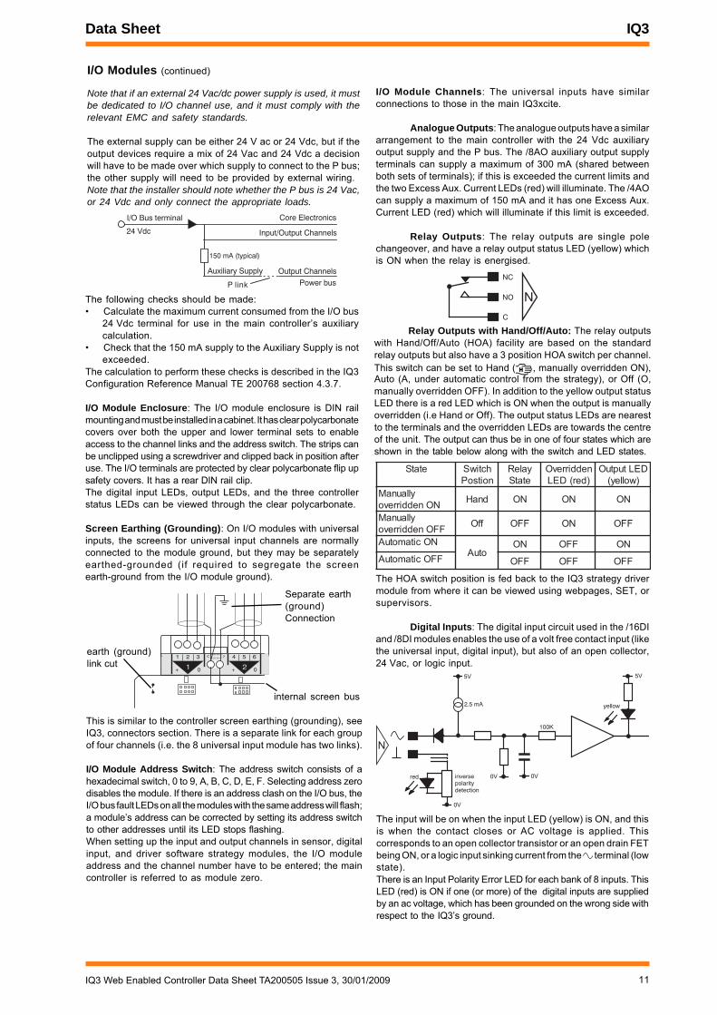
I/O Module Channels: The universal inputs have similarconnections to those in the main IQ3xcite.
Analogue Outputs: The analogue outputs have a similararrangement to the main controller with the 24 Vdc auxiliaryoutput supply and the P bus. The /8AO auxiliary output supplyterminals can supply a maximum of 300 mA (shared betweenboth sets of terminals); if this is exceeded the current limits andthe two Excess Aux. Current LEDs (red) will illuminate. The /4AOcan supply a maximum of 150 mA and it has one Excess Aux.Current LED (red) which will illuminate if this limit is exceeded.
Relay Outputs: The relay outputs are single polechangeover, and have a relay output status LED (yellow) whichis ON when the relay is energised.
Core Electronics
Auxiliary Supply Output Channels
150 mA (typical)
Input/Output Channels
Power busP link
I/O Bus terminal
24 Vdc
I/O Modules (continued)
Note that if an external 24 Vac/dc power supply is used, it mustbe dedicated to I/O channel use, and it must comply with therelevant EMC and safety standards.
The external supply can be either 24 V ac or 24 Vdc, but if theoutput devices require a mix of 24 Vac and 24 Vdc a decisionwill have to be made over which supply to connect to the P bus;the other supply will need to be provided by external wiring.Note that the installer should note whether the P bus is 24 Vac,or 24 Vdc and only connect the appropriate loads.
This is similar to the controller screen earthing (grounding), seeIQ3, connectors section. There is a separate link for each groupof four channels (i.e. the 8 universal input module has two links).
I/O Module Address Switch: The address switch consists of ahexadecimal switch, 0 to 9, A, B, C, D, E, F. Selecting address zerodisables the module. If there is an address clash on the I/O bus, theI/O bus fault LEDs on all the modules with the same address will flash;a module’s address can be corrected by setting its address switchto other addresses until its LED stops flashing.When setting up the input and output channels in sensor, digitalinput, and driver software strategy modules, the I/O moduleaddress and the channel number have to be entered; the maincontroller is referred to as module zero.
Relay Outputs with Hand/Off/Auto: The relay outputswith Hand/Off/Auto (HOA) facility are based on the standardrelay outputs but also have a 3 position HOA switch per channel.This switch can be set to Hand ( H , manually overridden ON),Auto (A, under automatic control from the strategy), or Off (O,manually overridden OFF). In addition to the yellow output statusLED there is a red LED which is ON when the output is manuallyoverridden (i.e Hand or Off). The output status LEDs are nearestto the terminals and the overridden LEDs are towards the centreof the unit. The output can thus be in one of four states which areshown in the table below along with the switch and LED states.
The following checks should be made:• Calculate the maximum current consumed from the I/O bus
24 Vdc terminal for use in the main controller’s auxiliarycalculation.
• Check that the 150 mA supply to the Auxiliary Supply is notexceeded.
The calculation to perform these checks is described in the IQ3Configuration Reference Manual TE 200768 section 4.3.7.
I/O Module Enclosure: The I/O module enclosure is DIN railmounting and must be installed in a cabinet. It has clear polycarbonatecovers over both the upper and lower terminal sets to enableaccess to the channel links and the address switch. The strips canbe unclipped using a screwdriver and clipped back in position afteruse. The I/O terminals are protected by clear polycarbonate flip upsafety covers. It has a rear DIN rail clip.The digital input LEDs, output LEDs, and the three controllerstatus LEDs can be viewed through the clear polycarbonate.
Screen Earthing (Grounding): On I/O modules with universalinputs, the screens for universal input channels are normallyconnected to the module ground, but they may be separatelyearthed-grounded (if required to segregate the screenearth-ground from the I/O module ground).
C
NC
NO N
etatS hctiwSnoitsoP
yaleRetatS
neddirrevO)der(DEL
DELtuptuO)wolley(
yllaunaMNOneddirrevo dnaH NO NO NO
yllaunaMFFOneddirrevo ffO FFO NO FFO
NOcitamotuAotuA
NO FFO NOFFOcitamotuA FFO FFO FFO
The HOA switch position is fed back to the IQ3 strategy drivermodule from where it can be viewed using webpages, SET, orsupervisors.
Digital Inputs: The digital input circuit used in the /16DIand /8DI modules enables the use of a volt free contact input (likethe universal input, digital input), but also of an open collector,24 Vac, or logic input.
5V5V
red
100K
0V
2.5 mA
0V0V
N
inversepolarity detection
yellow
The input will be on when the input LED (yellow) is ON, and thisis when the contact closes or AC voltage is applied. Thiscorresponds to an open collector transistor or an open drain FETbeing ON, or a logic input sinking current from the terminal (lowstate).There is an Input Polarity Error LED for each bank of 8 inputs. ThisLED (red) is ON if one (or more) of the digital inputs are suppliedby an ac voltage, which has been grounded on the wrong side withrespect to the IQ3’s ground.
12 IQ3 Web Enabled Controller Data Sheet TA200505 Issue 3, 30/01/2009
IQ3 Data Sheet
N
24 Vac ±20%
Load
N� � �
24 Vac Input
Open Collector (or Open Drain) Input
N� � �
� � � �
� � � � �� � �
� � �
Logic Input
The logic high level can be between 5 and 50 V (e.g. TTL, CMOS).The logic low level must be able to sink 3 mA. Note that the digitalinput will be ON when the logic input is low.
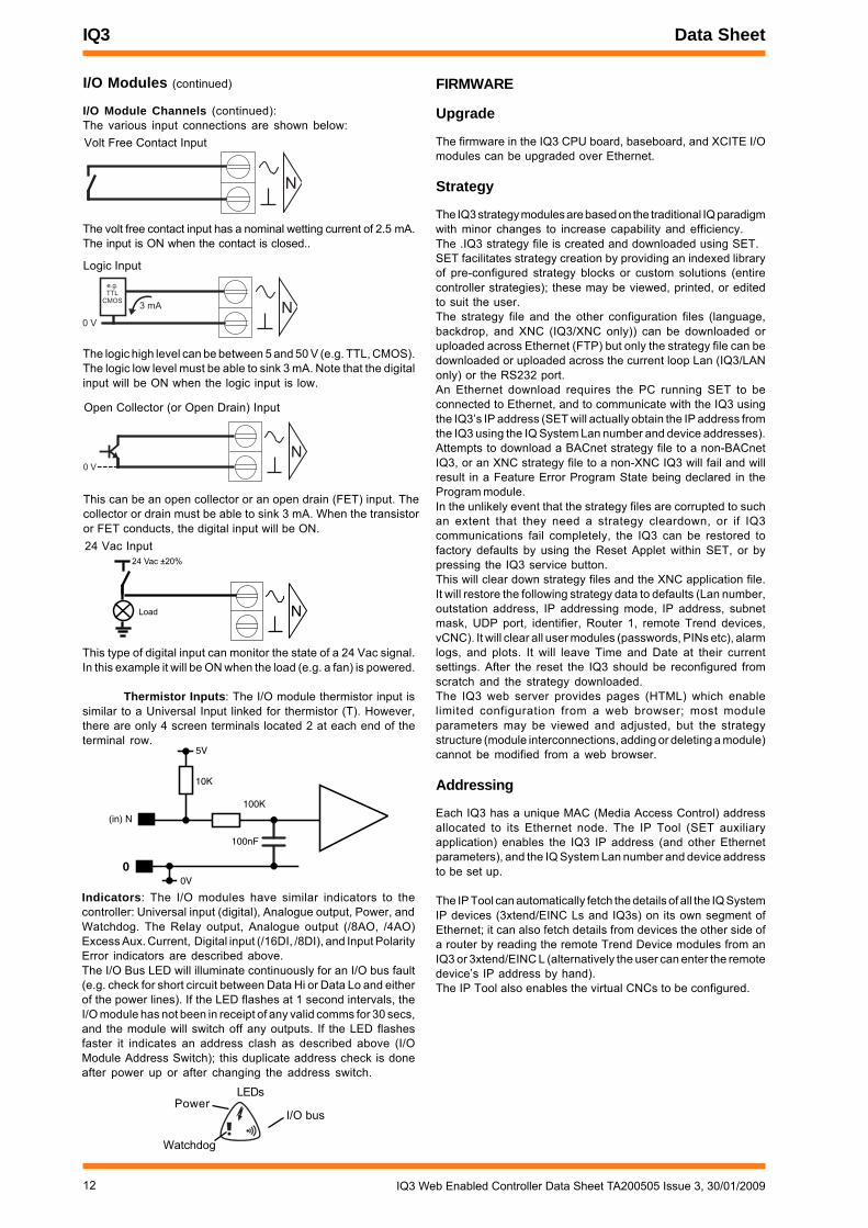
FIRMWARE
Upgrade
The firmware in the IQ3 CPU board, baseboard, and XCITE I/Omodules can be upgraded over Ethernet.
Strategy
The IQ3 strategy modules are based on the traditional IQ paradigmwith minor changes to increase capability and efficiency.The .IQ3 strategy file is created and downloaded using SET.SET facilitates strategy creation by providing an indexed libraryof pre-configured strategy blocks or custom solutions (entirecontroller strategies); these may be viewed, printed, or editedto suit the user.The strategy file and the other configuration files (language,backdrop, and XNC (IQ3/XNC only)) can be downloaded oruploaded across Ethernet (FTP) but only the strategy file can bedownloaded or uploaded across the current loop Lan (IQ3/LANonly) or the RS232 port.An Ethernet download requires the PC running SET to beconnected to Ethernet, and to communicate with the IQ3 usingthe IQ3’s IP address (SET will actually obtain the IP address fromthe IQ3 using the IQ System Lan number and device addresses).Attempts to download a BACnet strategy file to a non-BACnetIQ3, or an XNC strategy file to a non-XNC IQ3 will fail and willresult in a Feature Error Program State being declared in theProgram module.In the unlikely event that the strategy files are corrupted to suchan extent that they need a strategy cleardown, or if IQ3communications fail completely, the IQ3 can be restored tofactory defaults by using the Reset Applet within SET, or bypressing the IQ3 service button.This will clear down strategy files and the XNC application file.It will restore the following strategy data to defaults (Lan number,outstation address, IP addressing mode, IP address, subnetmask, UDP port, identifier, Router 1, remote Trend devices,vCNC). It will clear all user modules (passwords, PINs etc), alarmlogs, and plots. It will leave Time and Date at their currentsettings. After the reset the IQ3 should be reconfigured fromscratch and the strategy downloaded.The IQ3 web server provides pages (HTML) which enablelimited configuration from a web browser; most moduleparameters may be viewed and adjusted, but the strategystructure (module interconnections, adding or deleting a module)cannot be modified from a web browser.
Addressing
Each IQ3 has a unique MAC (Media Access Control) addressallocated to its Ethernet node. The IP Tool (SET auxiliaryapplication) enables the IQ3 IP address (and other Ethernetparameters), and the IQ System Lan number and device addressto be set up.
The IP Tool can automatically fetch the details of all the IQ SystemIP devices (3xtend/EINC Ls and IQ3s) on its own segment ofEthernet; it can also fetch details from devices the other side ofa router by reading the remote Trend Device modules from anIQ3 or 3xtend/EINC L (alternatively the user can enter the remotedevice’s IP address by hand).The IP Tool also enables the virtual CNCs to be configured.
N
Volt Free Contact Input
I/O Modules (continued)
I/O Module Channels (continued):The various input connections are shown below:
The volt free contact input has a nominal wetting current of 2.5 mA.The input is ON when the contact is closed..
This type of digital input can monitor the state of a 24 Vac signal.In this example it will be ON when the load (e.g. a fan) is powered.
Thermistor Inputs: The I/O module thermistor input issimilar to a Universal Input linked for thermistor (T). However,there are only 4 screen terminals located 2 at each end of theterminal row.
Indicators: The I/O modules have similar indicators to thecontroller: Universal input (digital), Analogue output, Power, andWatchdog. The Relay output, Analogue output (/8AO, /4AO)Excess Aux. Current, Digital input (/16DI, /8DI), and Input PolarityError indicators are described above.The I/O Bus LED will illuminate continuously for an I/O bus fault(e.g. check for short circuit between Data Hi or Data Lo and eitherof the power lines). If the LED flashes at 1 second intervals, theI/O module has not been in receipt of any valid comms for 30 secs,and the module will switch off any outputs. If the LED flashesfaster it indicates an address clash as described above (I/OModule Address Switch); this duplicate address check is doneafter power up or after changing the address switch.
5V
(in) N
10K
100K
00V
100nF
Power
Watchdog
I/O bus
LEDs
This can be an open collector or an open drain (FET) input. Thecollector or drain must be able to sink 3 mA. When the transistoror FET conducts, the digital input will be ON.
13IQ3 Web Enabled Controller Data Sheet TA200505 Issue 3, 30/01/2009
Data Sheet IQ3
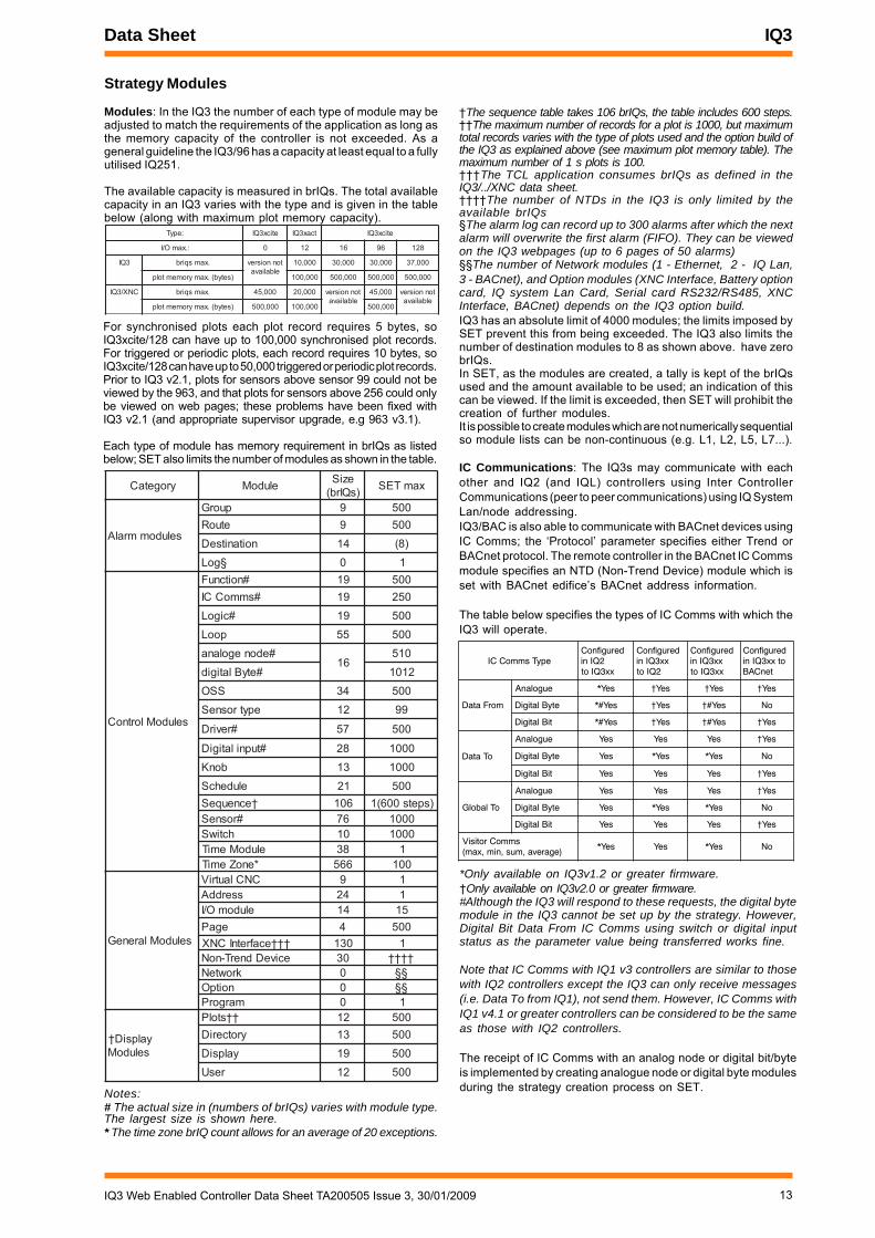
For synchronised plots each plot record requires 5 bytes, soIQ3xcite/128 can have up to 100,000 synchronised plot records.For triggered or periodic plots, each record requires 10 bytes, soIQ3xcite/128 can have up to 50,000 triggered or periodic plot records.Prior to IQ3 v2.1, plots for sensors above sensor 99 could not beviewed by the 963, and that plots for sensors above 256 could onlybe viewed on web pages; these problems have been fixed withIQ3 v2.1 (and appropriate supervisor upgrade, e.g 963 v3.1).
Each type of module has memory requirement in brIQs as listedbelow; SET also limits the number of modules as shown in the table.
yrogetaC eludoM eziS)sQIrb( xamTES
seludommralA
puorG 9 005etuoR 9 005
noitanitseD 41 )8(
§goL 0 1
seludoMlortnoC
#noitcnuF 91 005#smmoCCI 91 052
#cigoL 91 005
pooL 55 005
#edonegolana61
015
#etyBlatigid 2101
SSO 43 005
epytrosneS 21 99
#revirD 75 005
#tupnilatigiD 82 0001
bonK 31 0001
eludehcS 12 005†ecneuqeS 601 )spets006(1
#rosneS 67 0001hctiwS 01 0001
eludoMemiT 83 1*enoZemiT 665 001
seludoMlareneG
CNClautriV 9 1sserddA 42 1
eludomO/I 41 51egaP 4 005
ecafretnICNX ††† 031 1eciveDdnerT-noN 03 ††††
krowteN 0 §§noitpO 0 §§
margorP 0 1
† yalpsiDseludoM
stolP †† 21 005yrotceriD 31 005
yalpsiD 91 005
resU 21 005
Strategy Modules
Modules: In the IQ3 the number of each type of module may beadjusted to match the requirements of the application as long asthe memory capacity of the controller is not exceeded. As ageneral guideline the IQ3/96 has a capacity at least equal to a fullyutilised IQ251.
The available capacity is measured in brIQs. The total availablecapacity in an IQ3 varies with the type and is given in the tablebelow (along with maximum plot memory capacity).
:epyT eticx3QI tcax3QI eticx3QI
:.xamO/I 0 21 61 69 821
3QI .xamsqirb tonnoisrevelbaliava
000,01 000,03 000,03 000,73
)setyb(.xamyromemtolp 000,001 000,005 000,005 000,005
CNX/3QI .xamsqirb 000,54 000,02 tonnoisrevelbaliava
000,54 tonnoisrevelbaliava
)setyb(.xamyromemtolp 000,005 000,001 000,005
†The sequence table takes 106 brIQs, the table includes 600 steps.††The maximum number of records for a plot is 1000, but maximumtotal records varies with the type of plots used and the option build ofthe IQ3 as explained above (see maximum plot memory table). Themaximum number of 1 s plots is 100.†††The TCL application consumes brIQs as defined in theIQ3/../XNC data sheet.††††The number of NTDs in the IQ3 is only limited by theavailable brIQs§The alarm log can record up to 300 alarms after which the nextalarm will overwrite the first alarm (FIFO). They can be viewedon the IQ3 webpages (up to 6 pages of 50 alarms)§§The number of Network modules (1 - Ethernet, 2 - IQ Lan,3 - BACnet), and Option modules (XNC Interface, Battery optioncard, IQ system Lan Card, Serial card RS232/RS485, XNCInterface, BACnet) depends on the IQ3 option build.IQ3 has an absolute limit of 4000 modules; the limits imposed bySET prevent this from being exceeded. The IQ3 also limits thenumber of destination modules to 8 as shown above. have zerobrIQs.In SET, as the modules are created, a tally is kept of the brIQsused and the amount available to be used; an indication of thiscan be viewed. If the limit is exceeded, then SET will prohibit thecreation of further modules.It is possible to create modules which are not numerically sequentialso module lists can be non-continuous (e.g. L1, L2, L5, L7...).
IC Communications: The IQ3s may communicate with eachother and IQ2 (and IQL) controllers using Inter ControllerCommunications (peer to peer communications) using IQ SystemLan/node addressing.IQ3/BAC is also able to communicate with BACnet devices usingIC Comms; the ‘Protocol’ parameter specifies either Trend orBACnet protocol. The remote controller in the BACnet IC Commsmodule specifies an NTD (Non-Trend Device) module which isset with BACnet edifice’s BACnet address information.
The table below specifies the types of IC Comms with which theIQ3 will operate.
epyTsmmoCCIderugifnoC
2QInixx3QIot
derugifnoCxx3QIni
2QIot
derugifnoCxx3QInixx3QIot
derugifnoCotxx3QIni
tenCAB
morFataD
eugolanA seY* seY† seY† seY†
etyBlatigiD seY#* seY† seY#† oN
tiBlatigiD seY#* seY† seY#† seY†
oTataD
eugolanA seY seY seY seY†
etyBlatigiD seY seY* seY* oN
tiBlatigiD seY seY seY seY†
oTlabolG
eugolanA seY seY seY seY†
etyBlatigiD seY seY* seY* oN
tiBlatigiD seY seY seY seY†
smmoCrotisiV)egareva,mus,nim,xam(
seY* seY seY* oN
*Only available on IQ3v1.2 or greater firmware.†Only available on IQ3v2.0 or greater firmware.#Although the IQ3 will respond to these requests, the digital bytemodule in the IQ3 cannot be set up by the strategy. However,Digital Bit Data From IC Comms using switch or digital inputstatus as the parameter value being transferred works fine.
Note that IC Comms with IQ1 v3 controllers are similar to thosewith IQ2 controllers except the IQ3 can only receive messages(i.e. Data To from IQ1), not send them. However, IC Comms withIQ1 v4.1 or greater controllers can be considered to be the sameas those with IQ2 controllers.
The receipt of IC Comms with an analog node or digital bit/byteis implemented by creating analogue node or digital byte modulesduring the strategy creation process on SET.Notes:
# The actual size in (numbers of brIQs) varies with module type.The largest size is shown here.* The time zone brIQ count allows for an average of 20 exceptions.

14 IQ3 Web Enabled Controller Data Sheet TA200505 Issue 3, 30/01/2009
IQ3 Data Sheet
Web Pages
Information from an IQ3 controller can easily be accessed usinga Web browser (e.g. Internet Explorer v6.0), over any TCP/IPnetwork (e.g. the company Intranets, or the Internet). All that isrequired is the IP address or host name of the controller, and avalid user name and password (if users are set up in thecontroller). Once connection to the controller has been made, itis possible to view and adjust occupation times, view the alarmhistory, and view/adjust/graph individual module parameters.
Web pages may also be accessed by Mobile smart phones(Windows Mobile 2003 Second Edition), and PDAs (WindowsCE4); note that Mobile smart phones and PDAs cannot displaygraphs and right to left languages
Note that the operating system environment in which InternetExplorer runs must support Java; A Sun Java runtime environmentv1.4 or greater can be downloaded from Java.com.
Module parameters may be monitored and changed using webpages but module creation, deletion, and linking can only be doneusing SET.
The IQ3 is provided with a standard set of web pages whichcovers all accessible modules (see the example below of the listof knobs, and their current settings).
Graphical display pages (GraphIQs) which are configured usingIQ3 display and directory modules, can also be accessed (seethe example below of a dual boiler system GraphIQ page).
For further details of web pages see the the IQ3 ConfigurationReference Manual TA200768, the IQ3 Web User Guide, TC200631,and the IQ3 Graphical Display Pages Editor Manual, TE200629.
FIRMWARE (continued)
Alarms: The IQ3 will generate Network, General, and Itemalarms. Network alarms are generated by the Trend Networknodes, General alarms are generated when the IQ3 detects aproblem within its own hardware or program, and Item alarmsare generated by the strategy, and are normally due to a faultyplant condition.Network alarms are sent to supervisors or tools connectedto the local supervisor port or to the controller’s vCNC.General and Item alarms can either be sent in text, coded, orattribute format, and can be sent either to a designated Trend Lanaddress, to an IP address, as an email, or to a BACnet device(IQ3 BAC only). They are also stored locally in the Alarm Log.Only sensor, digital input, digital driver readback, and plot alarmscan be sent to a BACnet device.
For coded alarms the protocol limits the item number to 255maximum. For text alarms the maximum item label length is 20characters (although the 963 can be setup to use labels previouslylearnt).Sending an Email alarm requires the Email Server Address to beset up in the address module. The Email Server Address can beset up as an IP address, an internet domain name, or a hostname;the internet domain name or host name require a DNS serveraddress or a WINS server address respectively to be set up inthe network module so that the name can be resolved.
Timemaster: The IQ3 can act as a Timemaster for the Trendsystem (IQ1s - post 1989, IQ2s, IQ3s, and IQLs). It will maintain timeand date synchronisation for all IQ controllers and effect daylightsavings from a single source. However, each section of a systemseparated by auto-dialled links requires its own Timemaster.The IQ3 does not provide the Timekeeper functionality; this wasonly required for IQ90’s which did not have a battery backed realtime clock, and they should be supported by a pre-IQ3 Timekeepercontroller on their own Lan.Note that on a combined system (IQ3s with other IQs) an IQ3must be the Timemaster.The Timemaster IQ3 should be fitted with the battery option boardwhich will support it in the case of power failure.An IQ3 can be set by UTC time (Co-ordinated Universal Time,approximately the same as GMT), and has a UTC Offset parameterto define its time zone difference from UTC time.The UTC offset and daylight savings details should be set up inthe Timemaster so that all other IQs can be synchronisedaccordingly.
Language: The user can specify which language the IQ3 uses forthe display of web pages and for transmitted alarms. All the requiredtext is separately stored as a text file in SET and can be translatedto form a language file. The required files can be selected for eachSET project. English is always available in the controller, but SETenables a default language as well as additional languages to beselected. The appropriate language files will be downloaded to thecontroller when the strategy is downloaded. In the controller theAddress module has a language parameter which will be set bydefault to the default language, but can be changed to any one ofthe other available language files or English (e.g. change to Englishby setting the language parameter to ‘english’ on the addressmodule webpage). The IQ3 can use languages which require 8 bitcode (i.e. special or accented characters) and can also operatewith right to left languages (e.g. Chinese, Arabic).
Plots: The IQ3 plot modules can plot any connectable module output(analogue or digital). There are three types of plot module:synchronised, triggered, and periodic. Although all three types areBACnet interoperable, only periodic plots can be BACnet compliant.All plot modules can generate a buffer ready alarm when thenumber of records equals the notification threshold.
15IQ3 Web Enabled Controller Data Sheet TA200505 Issue 3, 30/01/2009
Data Sheet IQ3
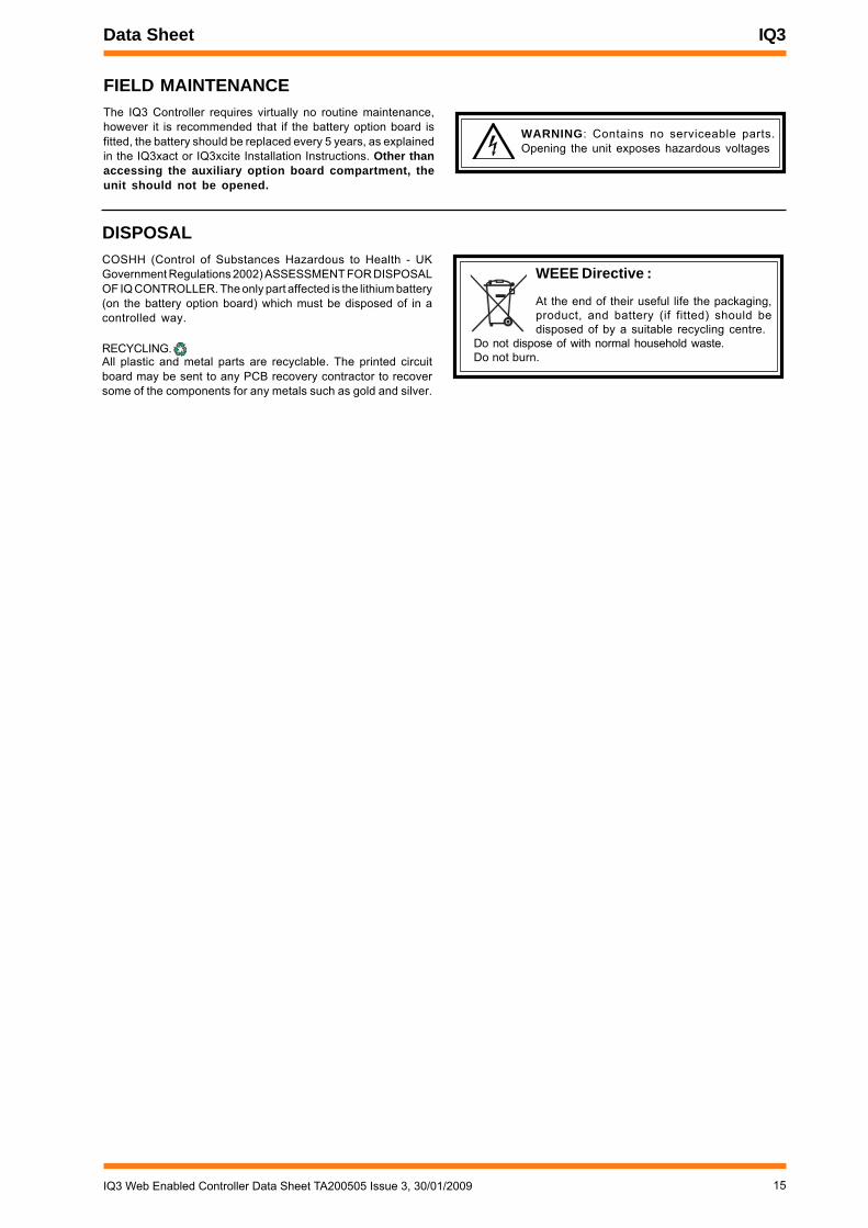
FIELD MAINTENANCEThe IQ3 Controller requires virtually no routine maintenance,however it is recommended that if the battery option board isfitted, the battery should be replaced every 5 years, as explainedin the IQ3xact or IQ3xcite Installation Instructions. Other thanaccessing the auxiliary option board compartment, theunit should not be opened.
WEEE Directive :
At the end of their useful life the packaging,product, and battery (if fitted) should bedisposed of by a suitable recycling centre.
Do not dispose of with normal household waste.Do not burn.
WARNING: Contains no serviceable parts.Opening the unit exposes hazardous voltages
DISPOSALCOSHH (Control of Substances Hazardous to Health - UKGovernment Regulations 2002) ASSESSMENT FOR DISPOSALOF IQ CONTROLLER. The only part affected is the lithium battery(on the battery option board) which must be disposed of in acontrolled way.
RECYCLING. All plastic and metal parts are recyclable. The printed circuitboard may be sent to any PCB recovery contractor to recoversome of the components for any metals such as gold and silver.
16 IQ3 Web Enabled Controller Data Sheet TA200505 Issue 3, 30/01/2009
IQ3 Data Sheet
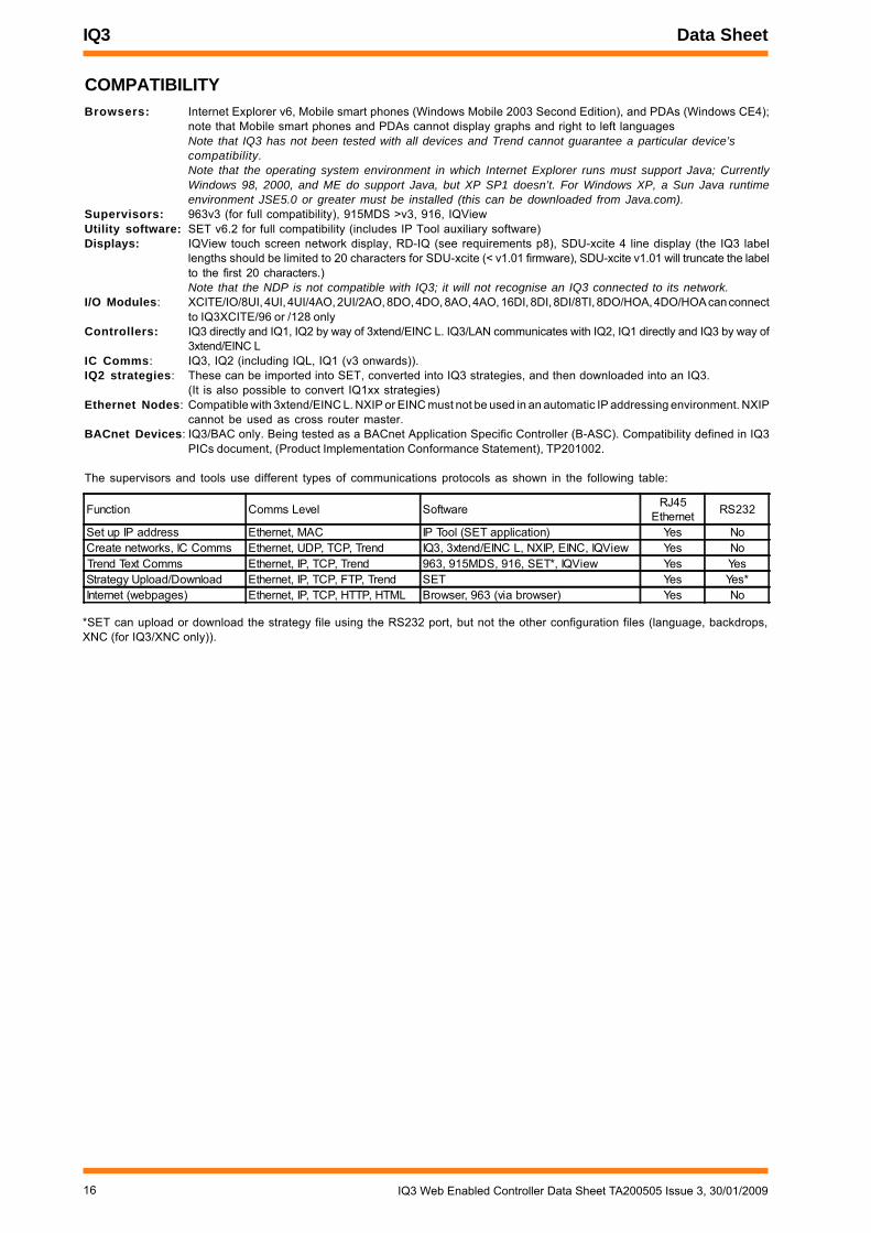
COMPATIBILITYBrowsers: Internet Explorer v6, Mobile smart phones (Windows Mobile 2003 Second Edition), and PDAs (Windows CE4);
note that Mobile smart phones and PDAs cannot display graphs and right to left languagesNote that IQ3 has not been tested with all devices and Trend cannot guarantee a particular device’scompatibility.Note that the operating system environment in which Internet Explorer runs must support Java; CurrentlyWindows 98, 2000, and ME do support Java, but XP SP1 doesn’t. For Windows XP, a Sun Java runtimeenvironment JSE5.0 or greater must be installed (this can be downloaded from Java.com).
Supervisors: 963v3 (for full compatibility), 915MDS >v3, 916, IQViewUtility software: SET v6.2 for full compatibility (includes IP Tool auxiliary software)Displays: IQView touch screen network display, RD-IQ (see requirements p8), SDU-xcite 4 line display (the IQ3 label
lengths should be limited to 20 characters for SDU-xcite (< v1.01 firmware), SDU-xcite v1.01 will truncate the labelto the first 20 characters.)Note that the NDP is not compatible with IQ3; it will not recognise an IQ3 connected to its network.
I/O Modules: XCITE/IO/8UI, 4UI, 4UI/4AO, 2UI/2AO, 8DO, 4DO, 8AO, 4AO, 16DI, 8DI, 8DI/8TI, 8DO/HOA, 4DO/HOA can connectto IQ3XCITE/96 or /128 only
Controllers: IQ3 directly and IQ1, IQ2 by way of 3xtend/EINC L. IQ3/LAN communicates with IQ2, IQ1 directly and IQ3 by way of3xtend/EINC L
IC Comms: IQ3, IQ2 (including IQL, IQ1 (v3 onwards)).IQ2 strategies: These can be imported into SET, converted into IQ3 strategies, and then downloaded into an IQ3.
(It is also possible to convert IQ1xx strategies)Ethernet Nodes: Compatible with 3xtend/EINC L. NXIP or EINC must not be used in an automatic IP addressing environment. NXIP
cannot be used as cross router master.BACnet Devices: IQ3/BAC only. Being tested as a BACnet Application Specific Controller (B-ASC). Compatibility defined in IQ3
PICs document, (Product Implementation Conformance Statement), TP201002.
The supervisors and tools use different types of communications protocols as shown in the following table:
*SET can upload or download the strategy file using the RS232 port, but not the other configuration files (language, backdrops,XNC (for IQ3/XNC only)).
Function Comms Level Software RJ45Ethernet RS232
Set up IP address Ethernet, MAC IP Tool (SET application) Yes NoCreate networks, IC Comms Ethernet, UDP, TCP, Trend IQ3, 3xtend/EINC L, NXIP, EINC, IQView Yes NoTrend Text Comms Ethernet, IP, TCP, Trend 963, 915MDS, 916, SET*, IQView Yes YesStrategy Upload/Download Ethernet, IP, TCP, FTP, Trend SET Yes Yes*Internet (webpages) Ethernet, IP, TCP, HTTP, HTML Browser, 963 (via browser) Yes No
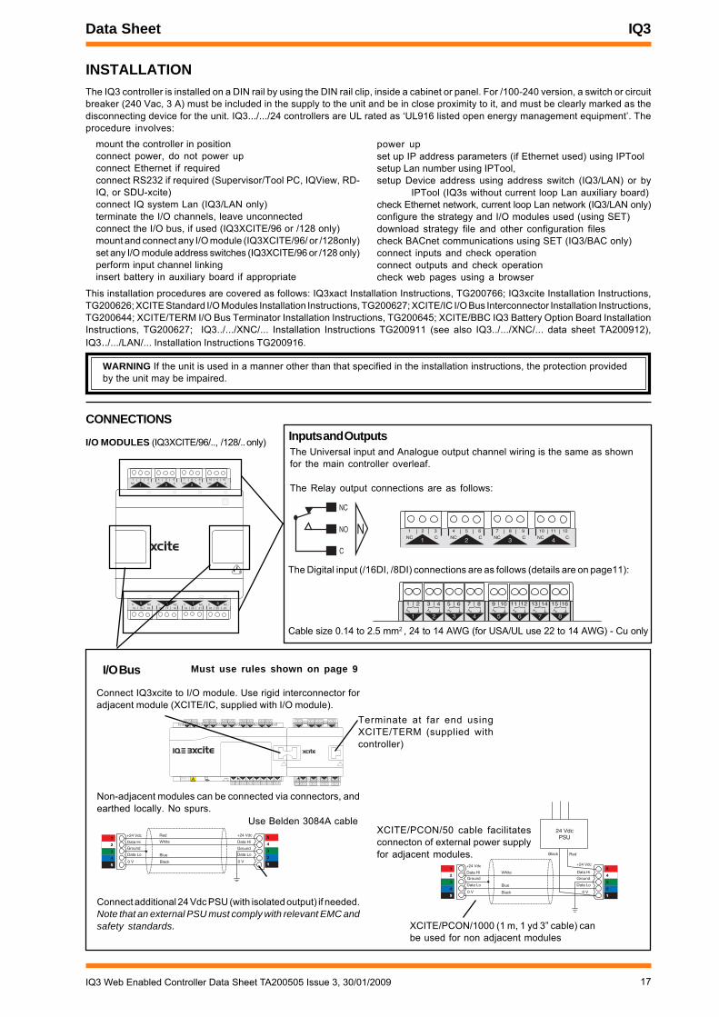
17IQ3 Web Enabled Controller Data Sheet TA200505 Issue 3, 30/01/2009
Data Sheet IQ3
INSTALLATIONThe IQ3 controller is installed on a DIN rail by using the DIN rail clip, inside a cabinet or panel. For /100-240 version, a switch or circuitbreaker (240 Vac, 3 A) must be included in the supply to the unit and be in close proximity to it, and must be clearly marked as thedisconnecting device for the unit. IQ3.../.../24 controllers are UL rated as ‘UL916 listed open energy management equipment’. Theprocedure involves:
mount the controller in positionconnect power, do not power upconnect Ethernet if requiredconnect RS232 if required (Supervisor/Tool PC, IQView, RD-IQ, or SDU-xcite)connect IQ system Lan (IQ3/LAN only)terminate the I/O channels, leave unconnectedconnect the I/O bus, if used (IQ3XCITE/96 or /128 only)mount and connect any I/O module (IQ3XCITE/96/ or /128only)set any I/O module address switches (IQ3XCITE/96 or /128 only)perform input channel linkinginsert battery in auxiliary board if appropriate
power upset up IP address parameters (if Ethernet used) using IPToolsetup Lan number using IPTool,setup Device address using address switch (IQ3/LAN) or by
IPTool (IQ3s without current loop Lan auxiliary board)check Ethernet network, current loop Lan network (IQ3/LAN only)configure the strategy and I/O modules used (using SET)download strategy file and other configuration filescheck BACnet communications using SET (IQ3/BAC only)connect inputs and check operationconnect outputs and check operationcheck web pages using a browser
This installation procedures are covered as follows: IQ3xact Installation Instructions, TG200766; IQ3xcite Installation Instructions,TG200626; XCITE Standard I/O Modules Installation Instructions, TG200627; XCITE/IC I/O Bus Interconnector Installation Instructions,TG200644; XCITE/TERM I/O Bus Terminator Installation Instructions, TG200645; XCITE/BBC IQ3 Battery Option Board InstallationInstructions, TG200627; IQ3../.../XNC/... Installation Instructions TG200911 (see also IQ3../.../XNC/... data sheet TA200912),IQ3../.../LAN/... Installation Instructions TG200916.
CONNECTIONS
I/O MODULES (IQ3XCITE/96/.., /128/.. only)
1
1 2 3
NC C 2
4 5 6
NC C 3
7 8 9
NC C 4
10 11 12
NC C
513 14 15
C NC 616 17 18C NC 7
19 20 21C NC 8
22 23 24C NC
24 VdcPSU
+24 Vdc
0 V
Data Hi
Data Lo
+24 Vdc
0 V
Data Hi
Data Lo
Ground Ground
White
Blue
Black
Black Red
�
�
�
�
�
�
�
�
�
�
I/O Bus
Connect IQ3xcite to I/O module. Use rigid interconnector foradjacent module (XCITE/IC, supplied with I/O module).
Connect additional 24 Vdc PSU (with isolated output) if needed.Note that an external PSU must comply with relevant EMC andsafety standards.
Inputs and OutputsThe Universal input and Analogue output channel wiring is the same as shownfor the main controller overleaf.
The Relay output connections are as follows:
C
NC
NO N
Non-adjacent modules can be connected via connectors, andearthed locally. No spurs.
+24 Vdc
0 V
Data Hi
Data Lo
+24 Vdc
0 V
Data Hi
Data Lo
Ground Ground
Red
White
Blue
Black
�
�
�
�
�
�
�
�
�
�
4 5 6
27 8 9
310 11 12
413 14 15
516 17 18
619 20 21
722 23 24
825 26 27
928 29 30
10+ 0+ 0 + 0 + 0 + 0 + 0+ 0+ 0+ 0
1 2 3
1+ 0
0 V24 V
24 V 34 35 36
12
37 38 39
13
40 41 42
14A
31 32 33P
11
43 44 45
15
46 47 48
16100-240 V
OK RXP 0 P 0 P 0P 0 P 0 P 0
24 V
P 13 14 15
5P 0
16 17 18
6P 0
19 20 21
7P 0
22 23 24
8P 0
1 2 3
1+ 0
4 5 6
2+ 0
7 8 9
3+ 0
10 11 12
4+ 0
Terminate at far end usingXCITE/TERM (supplied withcontroller)
Use Belden 3084A cable
Must use rules shown on page 9
XCITE/PCON/50 cable facilitatesconnecton of external power supplyfor adjacent modules.
XCITE/PCON/1000 (1 m, 1 yd 3” cable) canbe used for non adjacent modules
WARNING If the unit is used in a manner other than that specified in the installation instructions, the protection providedby the unit may be impaired.
1
1 2 3
NC C 2
4 5 6
NC C 3
7 8 9
NC C 4
10 11 12
NC C
The Digital input (/16DI, /8DI) connections are as follows (details are on page11):
1 2
1
3 4
2
5 6
3
7 8
4
9 10
5
11 12
6
13 14
7
15 16
8
Cable size 0.14 to 2.5 mm2 , 24 to 14 AWG (for USA/UL use 22 to 14 AWG) - Cu only
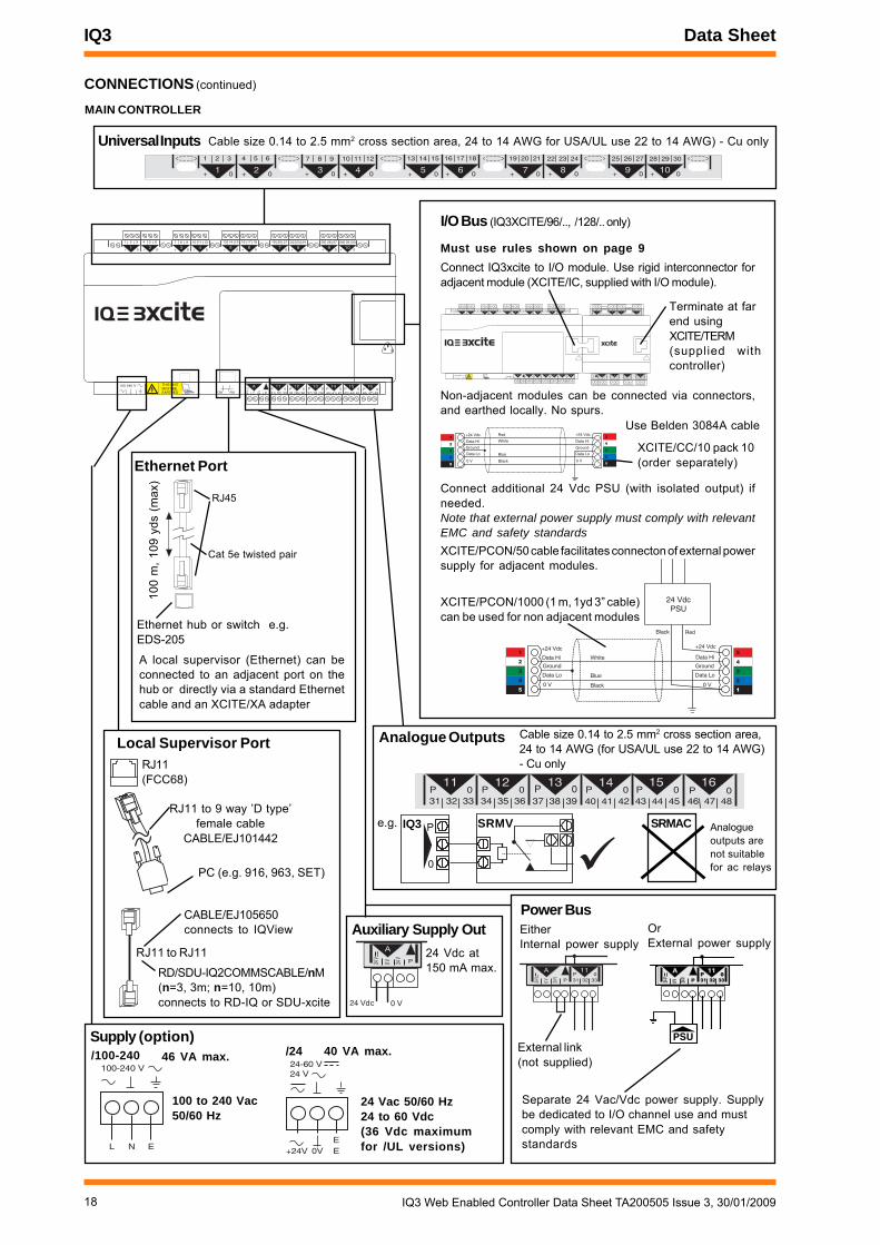
18 IQ3 Web Enabled Controller Data Sheet TA200505 Issue 3, 30/01/2009
IQ3 Data Sheet
CONNECTIONS (continued)
4 5 6
27 8 9
310 11 12
4
13 14 15
516 17 18
619 20 21
722 23 24
825 26 27
928 29 30
10+ 0+ 0 + 0 + 0 + 0 + 0+ 0+ 0+ 0
1 2 3
1+ 00 V24
V
24 V 34 35 36
12
37 38 39
13
40 41 42
14A
31 32 33P
11
43 44 45
15
46 47 48
16100-240 V
OK RXP 0 P 0 P 0P 0 P 0 P 0
� � � � � � � � � � � � � �� � � � � �
Universal Inputs
Supply (option)
Analogue Outputs
100-240 V
L N E
/100-240
Local Supervisor Port
RJ11 to 9 way ’D type’female cable
CABLE/EJ101442
PC (e.g. 916, 963, SET)
RJ11(FCC68)
Ethernet Port
4 5 6
27 8 9
310 11 12
413 14 15
516 17 18
619 20 21
722 23 24
825 26 27
928 29 30
10+ 0+ 0 + 0 + 0 + 0 + 0+ 0+ 0+ 0
1 2 3
1+ 0
34 35 36
12
37 38 39
13
40 41 42
14
31 32 33
11
43 44 45
15
46 47 48
16P 0 P 0 P 0P 0 P 0 P 0
4 5 6
27 8 9
310 11 12
413 14 15
516 17 18
619 20 21
722 23 24
825 26 27
928 29 30
10+ 0+ 0 + 0 + 0 + 0 + 0+ 0+ 0+ 0
1 2 3
1+ 0
0 V24 V
24 V 34 35 36
12
37 38 39
13
40 41 42
14A
31 32 33P
11
43 44 45
15
46 47 48
16100-240 V
OK RXP 0 P 0 P 0P 0 P 0 P 0
24 V
P 13 14 15
5P 0
16 17 18
6P 0
19 20 21
7P 0
22 23 24
8P 0
1 2 3
1+ 0
4 5 6
2+ 0
7 8 9
3+ 0
10 11 12
4+ 0
24 VdcPSU
+24 Vdc
0 V
Data Hi
Data Lo
+24 Vdc
0 V
Data Hi
Data Lo
Ground Ground
White
Blue
Black
Black Red
�
�
�
�
�
�
�
�
�
�
I/O Bus (IQ3XCITE/96/.., /128/.. only)
Connect IQ3xcite to I/O module. Use rigid interconnector foradjacent module (XCITE/IC, supplied with I/O module).
A
PSU
0V24V
24V
A
31 32 33P
11P 0P 0
A
0 V24 V
24 V
A
31 32 33P
11P 0
Separate 24 Vac/Vdc power supply. Supplybe dedicated to I/O channel use and mustcomply with relevant EMC and safetystandards
External link(not supplied)
Power BusEitherInternal power supply
OrExternal power supply
MAIN CONTROLLER
Terminate at farend usingXCITE/TERM(supplied withcontroller)
A
0 V24 V
24 V
A
P
24 Vdc 0 V
Auxiliary Supply Out24 Vdc at150 mA max.
XCITE/CC/10 pack 10(order separately)
Connect additional 24 Vdc PSU (with isolated output) ifneeded.Note that external power supply must comply with relevantEMC and safety standards
+24 Vdc
0 V
Data Hi
Data Lo
+24 Vdc
0 V
Data Hi
Data Lo
Ground Ground
Red
White
Blue
Black
�
�
�
�
�
�
�
�
�
�
Use Belden 3084A cable
Non-adjacent modules can be connected via connectors,and earthed locally. No spurs.
Must use rules shown on page 9
46 VA max.
Cat 5e twisted pair
RJ45
100
m, 1
09 y
ds (
max
)
Ethernet hub or switch e.g.EDS-205
A local supervisor (Ethernet) can beconnected to an adjacent port on thehub or directly via a standard Ethernetcable and an XCITE/XA adapter
XCITE/PCON/50 cable facilitates connecton of external powersupply for adjacent modules.
XCITE/PCON/1000 (1 m, 1yd 3” cable)can be used for non adjacent modules
+24V 0V EE
24 V24-60 V
/24
24 Vac 50/60 Hz24 to 60 Vdc(36 Vdc maximumfor /UL versions)
40 VA max.
100 to 240 Vac50/60 Hz
RJ11 to RJ11
CABLE/EJ105650connects to IQView
RD/SDU-IQ2COMMSCABLE/nM(n=3, 3m; n=10, 10m)connects to RD-IQ or SDU-xcite
e.g. IQ3 SRMVP
0
SRMAC Analogueoutputs arenot suitablefor ac relays
Cable size 0.14 to 2.5 mm2 cross section area, 24 to 14 AWG for USA/UL use 22 to 14 AWG) - Cu only
Cable size 0.14 to 2.5 mm2 cross section area,24 to 14 AWG (for USA/UL use 22 to 14 AWG)- Cu only
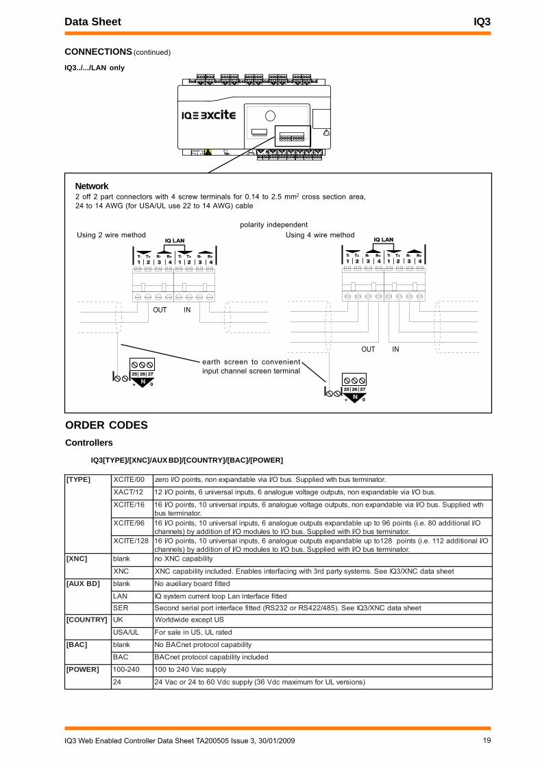
19IQ3 Web Enabled Controller Data Sheet TA200505 Issue 3, 30/01/2009
Data Sheet IQ3
ORDER CODESControllers
IQ3[TYPE]/[XNC]/AUX BD]/[COUNTRY]/[BAC]/[POWER]
CONNECTIONS (continued)
IQ3../.../LAN only4 5 6
27 8 9
310 11 12
413 14 15
516 17 18
619 20 21
722 23 24
825 26 27
928 29 30
10+ 0+ 0 + 0 + 0 + 0 + 0+ 0+ 0+ 0
1 2 3
1+ 0
0V24V
24V 34 35 36
12
37 38 39
13
40 41 42
14A
31 32 33P
11
43 44 45
15
46 47 48
16100-240 V
OK RXP 0 P 0 P 0P 0 P 0 P 0
25 26 27
N+ 0
1 2 3 41 2 3 4
IQ LANIQ LAN
T- T+ R- R+T- T+ R- R+
1 2 3 41 2 3 4T- T+ R- R+T- T+ R- R+
Network2 off 2 part connectors with 4 screw terminals for 0.14 to 2.5 mm2 cross section area,24 to 14 AWG (for USA/UL use 22 to 14 AWG) cable
INOUT
Using 2 wire method
25 26 27
N+ 0
1 2 3 41 2 3 4
IQ LANIQ LAN
T- T+ R- R+T- T+ R- R+
1 2 3 41 2 3 4T- T+ R- R+T- T+ R- R+
INOUT
Using 4 wire methodpolarity independent
]EPYT[ 00/ETICX .rotanimretsubhtwdeilppuS.subO/Iaivelbadnapxenon,stniopO/Iorez
21/TCAX .subO/Iaivelbadnapxenon,stuptuoegatloveugolana6,stupnilasrevinu6,stniopO/I21
61/ETICX htwdeilppuS.subO/Iaivelbadnapxenon,stuptuoegatloveugolana6,stupnilasrevinu01,stniopO/I61.rotanimretsub
69/ETICX O/Ilanoitidda08.e.i(stniop69otpuelbadnapxestuptuoeugolana6,stupnilasrevinu01,stniopO/I61.rotanimretsubO/IhtiwdeilppuS.subO/IotseludomO/Ifonoitiddayb)slennahc
821/ETICX O/Ilanoitidda211.e.i(stniop821otpuelbadnapxestuptuoeugolana6,stupnilasrevinu01,stniopO/I61.rotanimretsubO/IhtiwdeilppuS.subO/IotseludomO/Ifonoitiddayb)slennahc
]CNX[ knalb ytilibapacCNXon
CNX teehsatadCNX/3QIeeS.smetsysytrapdr3htiwgnicafretniselbanE.dedulcniytilibapacCNX
]DBXUA[ knalb dettifdraobyrailixuaoN
NAL dettifecafretninaLpooltnerrucmetsysQIRES teehsatadCNX/3QIeeS.)584/224SRro232SR(dettifecafretnitroplairesdnoceS
]YRTNUOC[ KU SUtpecxeediwdlroW
LU/ASU detarLU,SUnielasroF
]CAB[ knalb ytilibapaclocotorptenCABoN
CAB dedulcniytilibapaclocotorptenCAB
]REWOP[ 042-001 ylppuscaV042ot001
42 )snoisrevLUrofmumixamcdV63(ylppuscdV06ot42rocaV42
earth screen to convenientinput channel screen terminal
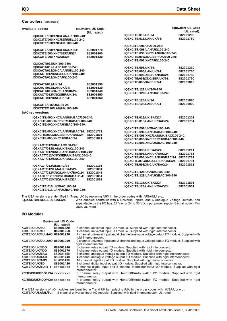
20 IQ3 Web Enabled Controller Data Sheet TA200505 Issue 3, 30/01/2009
IQ3 Data Sheet
Controllers (continued)
Available codes: equivalent US Code(UL rated)
IQ3XCITE/000/XNC/LAN/UK/100-240:IQ3XCITE/000/XNC/SER/UK/100-240:IQ3XCITE/000/XNC/UK/100-240:
IQ3XCITE/000/XNC/LAN/UK/24: 882001770IQ3XCITE/000/XNC/SER/UK/24: 882001800IQ3XCITE/000/XNC/UK/24: 882001820
IQ3XACT/012/UK/100-240:IQ3XACT/012/LAN/UK/100-240:IQ3XACT/012/XNC/LAN/UK/100-240:IQ3XACT/012/XNC/SER/UK/100-240:IQ3XACT/012/XNC/UK/100-240:
IQ3XACT/012/UK/24 882001190IQ3XACT/012/LAN/UK/24: 882001830IQ3XACT/012/XNC/LAN/UK/24: 882001840IQ3XACT/012/XNC/SER/UK/24: 882001850IQ3XACT/012/XNC/UK/24: 882001860
IQ3XCITE/016/UK/100-24IQ3XCITE/016/LAN/UK/100-240:
equivalent US Code(UL rated):
IQ3XCITE/016/UK/24 882001200IQ3XCITE/016/LAN/UK/24: 882001750
IQ3XCITE/096/UK/100-240:IQ3XCITE/096/LAN/UK/100-240:IQ3XCITE/096/XNC/LAN/UK/100-240:IQ3XCITE/096/XNC/SER/UK/100-240:IQ3XCITE/096/XNC/UK/100-240:
IQ3XCITE/096/UK/24: 882001210IQ3XCITE/096/LAN/UK/24: 882001760IQ3XCITE/096/XNC/LAN/UK/24: 882001780IQ3XCITE/096/XNC/SER/UK/24: 882001790IQ3XCITE/096/XNC/UK/24: 882001810
IQ3XCITE/128/UK/100-240IQ3XCITE/128/LAN/UK/100-240
IQ3XCITE/128/UK/24 882001890IQ3XCITE/128/LAN/UK/24 882001900
The USA versions are identified in Trend UK by replacing /UK/ in the order codes with /USA/UL/ e.g.:IQ3XACT/012/USA/UL/BAC/24: Web enabled controller with 6 Universal Inputs, and 6 Analogue Voltage Outputs, non
expandable by the I/O bus. 24 Vac or 24 to 36 Vdc input power supply. Bacnet option. ForUSA, UL rated.
I/O Modules
Equivalent US Code(UL rated)
XCITE/IO/UK/8UI 882001220 :8 channel universal input I/O module. Supplied with rigid interconnector.XCITE/IO/UK/4UI 882001250 :4 channel universal input I/O module. Supplied with rigid interconnector.XCITE/IO/UK/4UI/4AO 882001230 :4 channel universal input and 4 channel analogue voltage output I/O module. Supplied with
rigid interconnector.XCITE/IO/UK/2UI/2AO 882001260 :2 channel universal input and 2 channel analogue voltage output I/O module. Supplied with
rigid interconnector.XCITE/IO/UK/8DO 882001240 :8 channel relay output I/O module. Supplied with rigid interconnector.XCITE/IO/UK/4DO 882001270 :4 channel relay output I/O module. Supplied with rigid interconnector.XCITE/IO/UK/8AO 882001450 :8 channel analogue voltage output I/O module. Supplied with rigid interconnector.XCITE/IO/UK/4AO 882001440 :4 channel analogue voltage output I/O module. Supplied with rigid interconnector.XCITE/IO/UK/16DI 882001430 :16 channel digital input I/O module. Supplied with rigid interconnector.XCITE/IO/UK/8DI 882001420 :8 channel digital input output I/O module. Supplied with rigid interconnector.XCITE/IO/UK/8DI/8TI xxxxxxxxx :8 channel digital input and 8 channel thermistor input I/O module. Supplied with rigid
interconnector.XCITE/IO/UK/8DO/HOA xxxxxxxxx :8 channel relay output with Hand/Off/Auto switch I/O module. Supplied with rigid
interconnector.XCITE/IO/UK/4DO/HOA xxxxxxxxx :4 channel relay output with Hand/Off/Auto switch I/O module. Supplied with rigid
interconnector.
The USA versions of I/O modules are identified in Trend UK by replacing /UK/ in the order codes with /USA/UL/ e.g.:XCITE/IO/USA/UL/8UI: 8 channel universal input I/O module. Supplied with rigid interconnector. UL rated.
BACnet versionsIQ3XCITE/016/UK/BAC/24 882001201IQ3XCITE/016/LAN/UK/BAC/24: 882001751
IQ3XCITE/096/UK/BAC/100-240:IQ3XCITE/096/LAN/UK/BAC/100-240:IQ3XCITE/096/XNC/LAN/UK/BAC/100-240:IQ3XCITE/096/XNC/SER/UK/BAC/100-240:IQ3XCITE/096/XNC/UK/BAC/100-240:
IQ3XCITE/096/UK/BAC/24: 882001211IQ3XCITE/096/LAN/UK/BAC/24: 882001761IQ3XCITE/096/XNC/LAN/UK/BAC/24: 882001781IQ3XCITE/096/XNC/SER/UK/BAC/24: 882001791IQ3XCITE/096/XNC/UK/BAC/24: 882001811
IQ3XCITE/128/UK/BAC/100-240IQ3XCITE/128/LAN/UK/BAC/100-240
IQ3XCITE/128/UK/BAC/24 882001891IQ3XCITE/128/LAN/UK/BAC/24 882001901
IQ3XCITE/000/XNC/LAN/UK/BAC/100-240:IQ3XCITE/000/XNC/SER/UK/BAC/100-240:IQ3XCITE/000/XNC/UK/BAC/100-240:
IQ3XCITE/000/XNC/LAN/UK/BAC/24: 882001771IQ3XCITE/000/XNC/SER/UK/BAC/24: 882001801IQ3XCITE/000/XNC/UK/BAC/24: 882001821
IQ3XACT/012/UK/BAC/100-240:IQ3XACT/012/LAN/UK/BAC/100-240:IQ3XACT/012/XNC/LAN/UK/BAC/100-240:IQ3XACT/012/XNC/SER/UK/BAC/100-240:IQ3XACT/012/XNC/UK/BAC/100-240:
IQ3XACT/012/UK/BAC/24 882001191IQ3XACT/012/LAN/UK/BAC/24: 882001831IQ3XACT/012/XNC/LAN/UK/BAC/24: 882001841IQ3XACT/012/XNC/SER/UK/BAC/24: 882001851IQ3XACT/012/XNC/UK/BAC/24: 882001861
IQ3XCITE/016/UK/BAC/100-24IQ3XCITE/016/LAN/UK/BAC/100-240:

21IQ3 Web Enabled Controller Data Sheet TA200505 Issue 3, 30/01/2009
Data Sheet IQ3
Controller Accessories
Equivalent US CodeXCITE/BBC 882001040 :Battery option board increases protection time of clock (in case of input power supply failure)
to several years (e.g. for Timemaster).XCITE/IC/5 882001050 :Pack of 5 rigid I/O bus interconnectors for adjacent I/O modules (spare)XCITE/TERM/5 882001060 :Pack of 5 I/O bus terminators (spare)XCITE/CC/10 882001070 :Pack of 10 I/O bus connectors with screw terminals to facilitate wired connection (one
required each end).XCITE/PCON/50 882001080 :I/O bus interconnector (4 wide) for adjacent I/O modules to facilitate connection of external bus
power supplyXCITE/PCON/1000 882001090 :1 m, 1 yd 3” I/O bus connection cable (4 wide) between I/O modules to facilitate connection of external
bus power supplyCABLE/EJ101442 :Adaptor cable to connect PC to local supervisor portXCITE/XA/5 882001100 :Pack of 5 Ethernet connecter adaptors for direct connection of a PC to the IQ3 using a standard
Ethernet cablePSR/230/24-1.3 :1.3 A DIN rail mounted 24 Vdc power supply (isolated output) suitable for supplying I/O
modulesPSR/230/24-2.5 :2.5 A DIN rail mounted 24 Vdc power supply (isolated output) suitable for supplying I/O
modules
Peripherals
IQView Mono/SM/UK/24 :Surface mounting touch screen display with ‘Mono’* application including RJ11 toRJ11 RS232 cable
IQView Mono/SM/USA/UL/24 882001160 :as per UK version above plus UL ratedIQView/SM/UK/24 :Surface mounting touch screen display with standard* applicationIQView/SM/USA/UL24 882001140 :as per UK version above plus UL ratedIQView Mono/RPM/UK/24 :Rear panel mounting touch screen display with ‘Mono’* application including RJ11
to RJ11 RS232 cableIQView Mono/RPM/USA/UL/24 882001170 :as per UK version above plus UL ratedIQView/RPM/UK/24 :Rear panel mounting touch screen display with standard* applicationIQView/RPM/USA/UL/24 882001150 :as per UK version above plus UL rated*Note that IQView Mono/ has an RS232 communications interface; IQView/ (standard) also has current loop Lan and Ethernet interfacesSDU-XCITE/UK :Smart Display unit for IQ3 within UK label set. Wall mounting unit with 2x40 electroluminescent
display allowing viewing and adjustment of control parameters and timesSDU-XCITE/WSA/USA 882001490 :as per UK version plus wall sensor adaptor plate for mounting on USA wallbox.RD-IQ/K/UK :Wall mounting Room Display with local thermistor temperature sensor and setpoint controlRD-IQ/K/WSA/USA 882001500 :as per UK version plus wall sensor adaptor plate for mounting on USA wallbox.RD-IQ/KOS/UK :Wall mounting Room Display with local thermistor temperature sensor, setpoint
control, occupation override, and occupation status displayRD-IQ/KOS/WSA/USA 882001510 :as per UK version plus wall sensor adaptor plate for mounting on USA wallbox.RD-IQ/KOSF/UK :Wall mounting Room Display with local thermistor temperature sensor, setpoint
control, occupation override, occupation status display, and fan speed controlRD-IQ/KOSF/WSA/USA 882001520 :as per UK version plus wall sensor adaptor plate for mounting on USA wallbox.RD/SDU-IQ2COMMSCABLE/3M 882000450 :3 m, 3 yds 10” cable to connect RD-IQ or SDU-xcite to IQ3RD/SDU-IQ2COMMSCABLE/10M 882000460 :10 m, 11 yds cable to connect RD-IQ or SDU-xcite to IQ3SDU DOWNLOAD ADAPTOR 882000470 :(EJ105174) RJ11 socket to RJ11 plug, download adaptor cable for use with CABLE/
EJ10442 for SDU-xcite configuration by PC running SDU Tool (an applet running inSET available from your supplier's website and protected by licence)
Accessories
TP/1/1/22/HF/200 :200m of screened single twisted pair 0.34mm2 (22AWG) (Belden equivalent 8761NH), foruse on current loop Lan (IQ3/LAN version), input/output channel wiring.
TP/2/2/22/HF/200 :200m of screened twin twisted pair 0.34mm2 (22AWG) (Belden equivalent 8723NH), for useon current loop Lan (IQ3/LAN version).
EDS-205 :Unmanaged Ethernet switch with 5 off 10/100BaseT(X) ports.EDS-305-M-SC :Unmanaged Ethernet switch with 4 off 10/100BaseT(X) ports, 1 multimode100BaseFX
(fibre optic) port.IMC-101-M-SC :1 channel 10/100BaseT(X) to multimode 100BaseFX (fibre optic) converter.
Equivalent US Code

22 IQ3 Web Enabled Controller Data Sheet TA200505 Issue 3, 30/01/2009
IQ3 Data Sheet
SPECIFICATIONSMAIN CONTROLLER
Electrical
CPU :MCF5272CPU speed :66 MHzCycle time :sequence table 1sMemory :16 Mbyte SDRAM, and 8 Mbyte Flash.
IQ3xcite/128 :37000 briQs (module capacity see p13)IQ3xact :6000 briQs (module capacity see p13)
Input power supply voltage/100-240 :100 to 240 Vac ±10% 50/60 Hz/24 :24 to 60 Vdc ±10% (36 Vdc maximum
for /UL versions), 24 Vac ±15% 50/60 HzInput power supply consumption
/100-240 :6 VA minimumIQ3XCITE/000 :15 VA maximumIQ3XACT/012 :28 VA maximumIQ3XCITE/016 :39 VA maximumIQ3XCITE/096, /128 :56 VA maximum
/24 :5 VA minimumIQ3XCITE/000 :11 VA maximumIQ3XACT/012 :25 VA maximumIQ3XCITE/016 :28 VA maximumIQ3XCITE/096, /128 :40 VA maximum
Input Supply Leakage :Leakage current at 230 Vac, 50 Hz isless than 0.3 mA.
24 Vdc combined supply :24 Vdc ±10%, 700 mA maximum (typical)to supply 24 Vdc auxiliary supply terminals,I/O bus, RS232, the I/O channels (see page6). Output derated to 550 mA for inputpower supply <200 Vac.
24 Vdc auxiliary supply: Part of combined supply, 20 to 24 Vdclimited to 150 mA supplied to RS232,24 V auxiliary output supply, and may belinked to output power bus.
Fusing :No replaceable fuses required.24 Vdc combined supply :protected by a self resetting solid
state circuit breaker.RS232, 24 V :part of the combined supply to RS232,
24 V auxiliary output supply (and outputpower bus, if linked) is protected by150 mA current limit.
Power bus :protected by a 1.6 A multifuse.Power supply :protected against catastrophic failure
by a non-replaceable fuse.Analogue output :circuitry is protected against the wrong
connection of a non-isolated externalsupply by a non-replaceable fuse.
Power failure protection :All strategy and data in nonvolatile memory.Supercap maintains real time clock for upto 6 days (typical). Option to fit a batteryboard to maintain clock for up to severalyears in the case of input supply failure.
Battery option :XCITE/BBC, battery option boardincludes CR2032 3V lithium button cell.Feature also included on IQ3../.../LAN orIQ3../.../SER versions but battery notprovided.
Clock accuracy :30 s per month (typical).4-line display panel :SDU-xcite to local supervisor portEthernet :main bus, 10 BASE-T (IEEE 802.3).
Supports TCP/IP, FTPSupervisor Port
Transmission :RS232, EIA/TIA/232E, V28 supports IQSystem comms
Distance :15 m, 16 ydsBaud rate :9k6.Address :Selectable by software, 116 nodes
addressable (1, 4 to 119 excluding 2,3,10)set to be unique on Lan.
Baud rate :Selectable by board switches 9k6, 19k2- set to be same as other nodes on Lan.
Address :The IQ3 address on Lan is set by boardswitches. Set to be unique on network;116 nodes addressable (1 to 119excluding addresses 2,3, and 10)Virtual CNC address, supervisor portaddress to be configured in strategy.
Serial Port 2 :(IQ3../.../SER only)RS232 or RS422/485 selectable bysoftware. See IQ3../.../XNC data sheetfor details
I/O bus :(not fitted on IQ3xact or IQ3XCITE/00)maximum length 30 m, 33 yds, 15additional nodes maximum, 96 pointsmaximum. Signalling rate 125 kbits/s.Cable Belden 3084A.
Inputs/OutputsIQ3XCITE/00 :zero I/OIQ3XACT :6 universal inputs, 6 voltage outputsIQ3XCITE/16 :10 universal inputs, 6 voltage outputsIQ3XCITE/96 :10 universal inputs, 6 voltage outputs
expandable by adding I/O modules to 96points maximum
IQ3XCITE/128 :10 universal inputs, 6 voltage outputsexpandable by adding I/O modules to128 points maximum
Signal Cable :Universal inputs, and analogue voltageoutputs; TP/1/1/22/HF/200 recommended(Belden 8761)
Measurement Category :Universal inputs and analogue voltageoutputs are Measurement CAT I(EN61616:2001). They must beseparated from 230 Vac input powersupply by double or reinforced insulation.
Universal inputs :Channels 1 to 10, linkable for analoguevoltage (V), analogue current (I),thermistor (T) or digital (D).
Analogue voltage (V) :12 bit resolution. Minimum 60 dBseries mode rejection at input powersupply frequency. 0 to 10 V, inputresistance 200 k, accuracy 50 mVequivalent to ±0.5% of span.
Analogue current (I) :12 bit resolution (4096 steps - effective).Minimum 60 dB series mode rejection atinput power supply frequency. 0 to20 mA, input resistance 240 , accuracy0.5% of span (i.e. 100 μA). Looppowered input supply is 20 to 36 Vdc.
Thermistor (T) :12 bit resolution. Minimum 60 dB seriesmode rejection at input power supplyfrequency. Thermistor bridge resistor10 k 0.1%, accuracy 0.5% of span.Bridge supply 5 V.
elbaC duab6k9 duab2k91 fo.oNseriW
2819nedleB m0001)sdy0901(
m007)sdy567( 2
7029nedleB m0001)sdy0901(
m005)sdy545( 2
002/FH/22/1/1/PTdnerT)1678nedleB(
m007)sdy567(
m053)sdy083( 2
002/FH/22/2/2/PTdnerT)3278nedleB(
m005)sdy545(
m052)sdy072( 4
IQ Current Loop Lan :(IQ3../.../LAN only)Transmission :20 mA two wire current loop, opto-
isolated, polarity independent receiver,balanced transmitter
Distance :Dependent on cable type, see tablebelow:

23IQ3 Web Enabled Controller Data Sheet TA200505 Issue 3, 30/01/2009
Data Sheet IQ3
SPECIFICATIONS (continued)
Digital (D) :volt free contact. Count rate 30 Hz(minimum pulse width of 16.6 ms).Wetting current = 3 mA nominal. 5 Vsupply. Status LED per channel (ON =closed contact).
Analogue voltage outputs :Channels 11 to 16. 11 bitresolution. 0 to 10 V with 20 mA currentlimit, accuracy ±0.5% of span.
IndicatorsInputs :(yellow) Indicates status, only for digital
inputs (ON= contact closed)Analogue Outputs :(yellow) Lightintensity increases with output voltage
(power) :(green) ON when input power supply isconnected. Flashing at 1 second intervalsindicates power supply fault.
(watchdog) :(red) ON if controller has a softwarefault
(I/O bus) :(red, not fitted on IQ3xact) On if there isan I/O bus fault.
OK :(green) Normally called LINK on Ethernetsystems. ON indicates a good Ethernetconnection.
RX :(yellow) Flashes when packet of datais being received across the Ethernet.
IQ Current Loop Lan Indicators :IQ3../.../LAN onlyTX :(yellow) ON if current is flowing from
the current loop network transmitterRX :(yellow) ON if current is entering the
current loop network receiverOK :(green) ON if IQ3 successfully
communicating over current loopnetwork.
Mechanical
DimensionsController :263 mm (10.35”) x 150 mm (5.91”) max.
x 46 mm (1.81”)IQ3../.../LAN, or IQ3../.../SER 263 mm(10.35”) x 150 mm (5.91”) max. x 56 mm(2.2”)
Material :PolycarbonateWeight
Controller :702 gm (1.5 lb)Connectors
Input power supply :2 part connector with 3 rising cage clampscrew terminals for 0.5 to 2.5 mm2 crosssection area (14 to 20 AWG) cable.
I/O :2 part connectors with rising cage clampscrew terminals for 0.14 to 2.5 mm2 crosssection area, 24 to 14 AWG (for USA/ULuse 22 to 14 AWG) cable. Use coppercable only.
Screens :Single part connectors with rising cageclamp screw terminals for 0.14 to 2.5mm2 cross section area, 24 to 14 AWG(for USA/UL use 22 to 14 AWG) cable.Use copper cable only.
Supervisor port :RJ11 (FCC68), for IQ System utilitysoftware, supervisor, RD-IQ, SDU-xcite,or IQView. Connected by adaptor cable(see order codes section). Can supplysignal and power.
Ethernet :RJ45 connector, unshielded or shieldedtwisted pair (UTP or FTP) cable 10 Mbps,100 m (109 yds), 10 BASE-T. Cable andconnectors are available (see productcodes). Connect local supervisor(Ethernet) by way of adjacent hub ordirectly using standard Ethernet cableand XCITE/XA adaptor
I/O bus :(not fitted on IQ3xact or IQ3XCITE/00) 5wide connector. For expandablecontroller only, connect with special rigidinterconnector (XCITE/IC, supplied withI/O Module) to adjacent module, or useconnector with screw terminals (XCITE/CC/10 - pack of 10) and wire in Belden3084A or equivalent. Last connectionrequires termination (XCITE/TERMsupplied with IQ3xcite controller only).Special 4 wide cables available tofacilitate connection of additional I/O buspower supply; XCITE/PCON/50 foradjacent I/O module, XCITE/PCON/1000for cable connection to I/O module up to1 m, 1 yd 3”. The maximum current thatcan be passed through the I/O moduleusing the 24 Vdc and 0 V terminals fromone module to the next is 2.5 A.
Environmental
EMCEmissions :EN61000-6-3:2001Immunity :EN61000-6-2:2001
SafetyEU :EN61010-1:2001
(Installation Category III - f ixedinstallations)
USA/Canada :/24 only. UL rated as ‘UL916 listed openenergy management equipment’
Canada :CSA22.2 No. 205-M1983 - SignalEquipment
Protection :IP20, NEMA1Ambient limits
storage :-10 °C (14 °F) to +50 °C (122 °F)operating :0 °C (32 °F) to 45 °C (113 °F)humidity :0 to 90 %RH non-condensing
Version This document covers:Firmware :v2.1Boards
IQ3 :/100-240 Baseboard AM104979 Issue 3/24 Baseboard AM105463 Issue 3CPU board AM104700 Issue 1/LAN auxiliary board AM105147 issue 1
I/O bus :XCITE/IC AM105225 Issue 1XCITE/TERM AM105226 Issue 1
I/O MODULES (for use with IQ3XCITE/96 only)
Electrical
CPU :microprocessor PIC 18F458Input power supply voltage :24 Vdc ±15%Input power supply consumption :Maximum: 8DO=100 mA,
4DO=60 mA, 8UI=180 mA, 4UI=100 mA,16DI=36 mA, 8DI=28 mA, 8DI/8TI=30 mA,4UI/4AO=180 mA (+Aux supply 150 mA),2UI/2AO=100 mA (+Aux supply 150 mA),8AO=180 mA (+Aux supply 300 mA),4AO=100 mA (+Aux supply 150 mA),8DO/HOA=100mA, 4DO/HOA=60 mA, -see page 10 for calculation.
Auxiliary output supply :(AO only) 18 to 24 Vdc, limited to 150 mAper bank of four AO.
Fusing :no replaceable fuses required.Auxiliary output supply :protected by a 150 mA current limit.Analogue output bus :protected by a 1.6 A multifuse.Analogue output circuitry :protected against the wrong
connection of a non-isolated externalsupply by a non-replaceable fuse.
I/O bus :maximum length 30 m (33 yds), 15additional nodes maximum, 96 pointsmaximum. Signalling rate 125 kbits/s.Cable Belden 3084A (see rules page 8).

IQ3 Data Sheet
24 IQ3 Web Enabled Controller Data Sheet TA200505 Issue 3, 30/01/2009
Trend Control Systems LimitedP.O. Box 34, Horsham, West Sussex, RH12 2YF, UK. Tel:+44 (0)1403 211888 Fax:+44 (0)1403 241608 www.trend-controls.comTrend Control Systems USA6670 185th Avenue NE, Redmond, Washington 98052, USA. Tel: (425)897-3900, Fax: (425)869-8445 www.trend-controls.com
Please send any comments about this or any other Trend technical publication to [email protected]
© 2009 Honeywell Technologies Sàrl, ECC Division. All rights reserved. Manufactured for and on behalf of the Environmental and Combustion ControlsDivision of Honeywell Technologies Sàrl, Z.A. La Pièce, 16, 1180 Rolle, Switzerland by its Authorized Representative, Trend Control Systems Limited.
Trend Control Systems Limited reserves the right to revise this publication from time to time and make changes to the content hereof withoutobligation to notify any person of such revisions or changes.
SPECIFICATIONS (continued)
Inputs/outputs :selectable from range of 8UI, 4UI, 4UI/4VO,2UI/2VO, 8DO, 4DO, 16DI, 8DI, 8DI/8TI,8AO, 4AO, 8DO/HOA, or 4DO/HOA.
Key: UI Universal inputDI Digital inputTI Thermistor inputVO Analogue voltage outputRO Relay output
Signal Cable :Universal inputs, and analogue voltageoutputs; TP/1/1/22/HF/200 recommended(Belden 8761)
Universal input :as for main controllerAnalogue voltage output :as for main controller except 10 bit
resolutionRelay output :Relay outputs with LED (yellow) status
indication (on = energised) per channel.Single pole changeover relays. Outputsrated at 5 A maximum for 240 Vac singlephase only (use same phase throughout)inductive, (cos>=0.4), or resistive load,30 Vdc (resistive load). Reduce to 2 Afor 24 Vdc (inductive load, T<=30 ms).For /USA only, UL rating applies up to240 Vac (120 VA) maximum. Arcsuppression recommended, (see RelayOutput Arc Suppression InstallationInstructions TG200208).
Relay output with Hand/Off/Auto:As for relay output above plus single 3way switch per channel to select eithermanual override ON (Hand), manualoverride off (Off) or automatic control(Auto) and additional LED (red) per channelto indicate manual override condition.
Thermistor input :12 bit resolution. Minimum 60 dB seriesmode rejection at input power supplyfrequency. Thermistor bridge resistor10 k 0.1%, accuracy 0.5% of span.Bridge supply 5 V.
Digital input :volt free contact, 24 Vac , open collector(or drain) or logic input. Count rate 30 Hz(minimum pulse width of 16.6 ms). 5 Vsupply. Status LED per channel.Volt free contact input: Wetting current= 3 mA nominal. (ON = closed contact.)24 Vac input: 24 Vac ±20%. Must befloating or earthed (grounded) to sameearth (ground) as IQ3, polaritydependent. (ON = load powered.)Open collector (or Drain) input: Must beable to sink 3 mA. Must be earthed(grounded) to same earth (ground) asIQ3, Polarity dependent. (ON =transistor/FET conducts.)Logic input: Logic high level 5 to 50 V.Logic low level must be able to sink 3 mA.(ON = logic low.)
IndicatorsInputs :(yellow) Indicates status, only for digital
inputs (ON= contact closed or equivalent)Analogue Outputs :(yellow) Light intensity increases with
output voltage.
Relay Outputs :(yellow). Indicates relay status (ON =relay energised)
Manual override :(red). Indicates the relay output channelis manually overridden. /8DO/HOA,/4DO/HOA only.
Excess Aux. Current:(red) Indicates maximum auxiliarycurrent exceeded. /8AO, /4AO only
Input Polarity Error :(red) Indicates 24 Vac input groundingerror (ON=error). /16DI, /8DI only.
(power) :(green) ON when supply is connected (watchdog) :(red) ON if module has a software fault
(I/O bus) :(red) On if there is an I/O bus fault.Flashes at 1 second intervals if the I/Omodule has not been in receipt of anyvalid comms for 30 secs (outputs will beswitched off). Flashes faster if anaddress clash on I/O bus, or the addresshas been set to zero (I/O moduledisabled).
Mechanical
DimensionsI/O Module :130 mm (5.12”) x 150 mm (5.91”) max.
x 46 mm (1.8”)Material :PolycarbonateProtection :IP20, NEMA1Weight
I/O Module :332 gm, 0.73 lb (approx.)Connectors
Power in :2 part connector with 3 rising cage clampscrew terminals for 0.5 to 2.5 mm2 crosssection area (14 to 20 AWG) cable.
I/O :2 part connectors with rising cage clampscrew terminals for 0.14 to 2.5 mm2 crosssection area, 24 to 14 AWG (for USA/ULuse 22 to 14 AWG) cable. Use coppercable only.
Screens :Single part connectors with rising cageclamp screw terminals for 0.14 to 2.5mm2 cross section area, 24 to 14 AWG(for USA/UL use 22 to 14 AWG) cable.
I/O bus :5 wide connector. Connect with specialrigid interconnector (XCITE/IC suppliedwith I/O Module) to adjacent module orcontroller, or use connector with screwterminals (XCITE/CC/10 - pack of 10) andwire in Belden 3084A or equivalent. Lastconnection requires termination(XCITE/TERM supplied with controller).The maximum current that can be passedthrough the I/O module through the 24 Vdcand 0 V terminals from one module to thenext is 2.5 A. Also see main controller fordetails of special cables.
Environmental :as for main controller except:
Safety USA/Canada :UL rated as ‘UL 916 listed accessory toopen energy management equipment’.
Version This document covers:Firmware v1.019Boards /8DO, /4DO: AM105145 Issue 2
/8 UI, /4UI, /4UI/4AO, /2UI/2AO: AM105146issue 1/16DI, /8DI, /8DI/8TI: AM105825 issue 2/8AO, /4AO: AM105873 issue 1/HOA sub board AM105973 issue 2