installation instructions 3xtend/einc l/24 · installation instructions 3xtend/einc l/24 1.3...
TRANSCRIPT
13xtend/EINC L/24 Installation Instructions TG200811 Issue 1/C 4/6/07
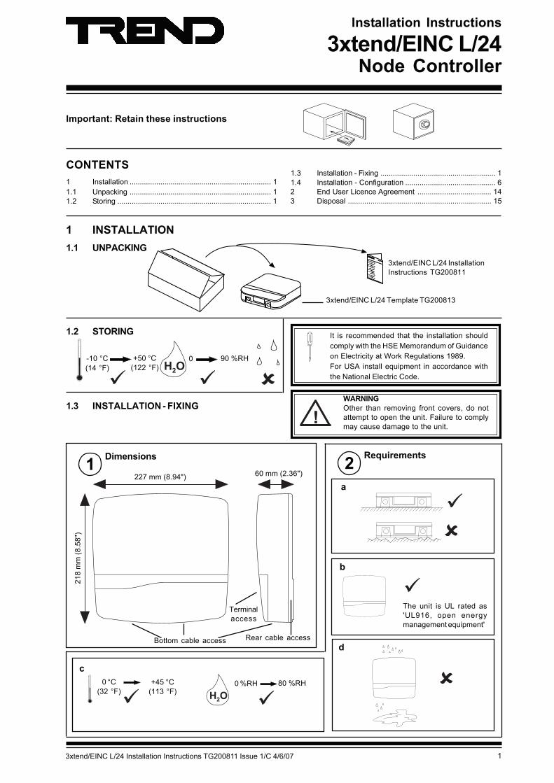
Important: Retain these instructions
Installation Instructions
3xtend/EINC L/24Node Controller
1.2 STORING
60 mm (2.36")227 mm (8.94")
218
mm
(8.5
8")
Dimensions Requirements
a
d
���
0 °C(32 °F)
+45 °C(113 °F)
0 %RH 80 %RH
c
1 2
���
+50 °C(122 °F)
0-10 °C(14 °F)
90 %RH
CONTENTS1 Installation ..................................................................... 11.1 Unpacking ..................................................................... 11.2 Storing ........................................................................... 1
1.3 Installation - Fixing ........................................................ 11.4 Installation - Configuration ............................................ 62 End User Licence Agreement .................................... 143 Disposal ...................................................................... 15
1.3 INSTALLATION - FIXING
The unit is UL rated as'UL916, open energymanagement equipment'
Bottom cable access
Terminalaccess
Rear cable access
b
It is recommended that the installation shouldcomply with the HSE Memorandum of Guidanceon Electricity at Work Regulations 1989.For USA install equipment in accordance withthe National Electric Code.
!WARNINGOther than removing front covers, do notattempt to open the unit. Failure to complymay cause damage to the unit.
1 INSTALLATION1.1 UNPACKING
3xtend/EINC L/24 InstallationInstructions TG200811
3xtend/EINC L/24 Template TG200813
2 3xtend/EINC L/24 Installation Instructions TG200811 Issue 1/C 4/6/07
3xtend/EINC L/24 Installation Instructions
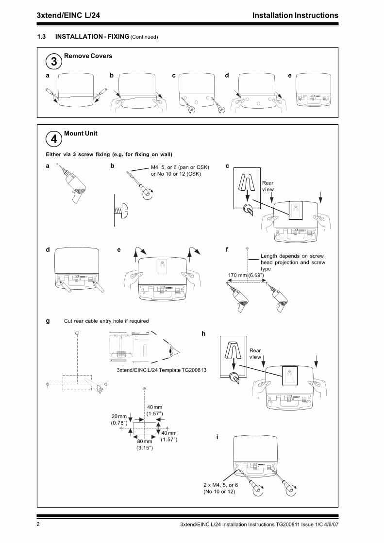
1.3 INSTALLATION - FIXING (Continued)
Remove Covers3
1 2 3 4 5 6 7 8 9 10
a b c d e
1 2 3 4 5 6 7 8 9 10
Mount Unit4Either via 3 screw fixing (e.g. for fixing on wall)
a b cM4, 5, or 6 (pan or CSK)or No 10 or 12 (CSK)
d e
1 2 3 4 5 6 7 8 9 10
1 2 3 4 5 6 7 8 9 10
f
170 mm (6.69”)
Rearview
Length depends on screwhead projection and screwtype
i
1 2 3 4 5 6 7 8 9 10
2 x M4, 5, or 6(No 10 or 12)
g Cut rear cable entry hole if required
h
1 2 3 4 5 6 7 8 9 10
Rearview
80 mm(3.15”)
40 mm(1.57”)
40 mm(1.57”)
20 mm(0.78”)
��������� ����������� �������� ��������� �������������
����������������� �������������
�����������������������
������� �� �� ��������������������� ��
�������������� ��� ����� �� � �!���"!����� � ��!� #�$��������%������������������&��!��"� ���!��������!����%'��!����$��"�����������%����#�� ���% ��!�� � ��� ���!��"� (
������������ ������������
�����������������������������
� � !�"� ��#� $����%�#������ &'���"#� ($��� �)*� +���� � ,��- ��
*%"��.�����%����%������������������/��
0��%������� ��1�2��3%���� (�-������ ��11����4�3%��$�'������5'�����(�% ���6��� -��&'���6�,����/+7�(�-������ ����0�-�%� �4���88�9�/
*%"��+,������������������8��
NOTE: Print to size.Check dimensions below
10 cm 4"
A 3 hole fixingScrew size 4 off M4 x 16Hole/drill 5mm
or alternatively
B 3 hole fixing(Do not use template for 3 hole fixing, see LERN../SM installation instructions, TGxxxxxx sheet 1 step x.)
A A
A A
B
B B
8 mm (0.31”)
170 mm (6.69”)
19
6 m
m (
3.7
8”)
126 mm (4.96”)
75 mm (2.95”)
80 mm (3.15”)
40
mm
(1
.57
”)
40 mm (1.57”)
20
mm
(0.7
8”)
37.5 mm (1.48”)
rear cable entry cutout
3xtend/EINC L/24 Template TG200813

33xtend/EINC L/24 Installation Instructions TG200811 Issue 1/C 4/6/07
Installation Instructions 3xtend/EINC L/24
1.3 INSTALLATION - FIXING (Continued)
Mount Unit (Continued)4Or via 4 screw fixing (e.g. fixing on a panel)
a b
c 4 x M4 x 16 mm
10 mmMax
126 mm (4.96”)
75 mm(2.95”)
196
mm
(3.7
8”)
80 mm (3.15”)
40 m
m(1
.57”
)
40 mm (1.57”)
8 mm(0.31”)
Cut rear cable entry holeif required
��������� ����������� �������� ��������� �������������
����������������� �������������
�����������������������
������� �� �� ��������������������� ��
�������������� ��� ����� �� � �!���"!����� � ��!� #�$��������%������������������&��!��"� ���!��������!����%'��!����$��"�����������%����#�� ���% ��!�� � ��� ���!��"� (
������������ ������������
�����������������������������
� � !�"� ��#� $����%�#������ &'���"#� ($��� �)*� +���� � ,��- ��
*%"��.�����%����%������������������/��
0��%������� ��1�2��3%���� (�-������ ��11����4�3%��$�'������5'�����(�% ���6��� -��&'���6�,����/+7�(�-������ ����0�-�%� �4���88�9�/
*%"��+,������������������8��
NOTE: Print to size.Check dimensions below
10 cm 4"
A 3 hole fixingScrew size 4 off M4 x 16Hole/drill 5mm
or alternatively
B 3 hole fixing(Do not use template for 3 hole fixing, see LERN../SM installation instructions, TGxxxxxx sheet 1 step x.)
A A
A A
B
B B
8 mm (0.31”)
170 mm (6.69”)
19
6 m
m (
3.7
8”)
126 mm (4.96”)
75 mm (2.95”)
80 mm (3.15”)
40
mm
(1
.57
”)
40 mm (1.57”)
20
mm
(0.7
8”)
37.5 mm (1.48”)
rear cable entry cutout
3xtend/EINC L/24 Template TG200813
4 holes Ø 5 mm
5 Route Cables
1 2 3 4 5 6 7 8 9 10
Rear entry
Fit M20 (¾”) cableglands
Bottom entry
ca b
8 mm Allen key

4 3xtend/EINC L/24 Installation Instructions TG200811 Issue 1/C 4/6/07
3xtend/EINC L/24 Installation Instructions
Connect Power
WARNING: This apparatus must be earthed (viasupply earth/ground terminal).
DO NOTSWITCH ON
�
�
28 to 36 Vdc or 24 Vac ±10 %, 50/60 Hz, Consumption <= 8VA
Terminal size 0.5 to 2.5mm2 (14 to 20 AWG)
230 Vac
Using the ACC/24VAC transformer Using the PSR/230/24-2.5 power supply
1.3 INSTALLATION - FIXING (Continued)
6
Connect Ethernet7
Ethernet
1 2 3 4 5 6 7 8 9 10
100
m (
109
yds)
Ethernet hub/switch
Connect to an Ethernet hubUse Ethernet cable.
1 2 3 4 5 6 7 8 9 10
28 - 36 V24 V ~
24 Vac 24 Vac E28 Vdc +28V 0V E
~
EINC L
RJ45 Connector
RJ45 Connector
Maximum Cable distance100 m (109 yds)
IQ SystemProductsEngineeringGuide TE200369
Using a 230V/24 Vac transformer
Some transformers (as in typical plant roominstallions) are earthed on one side of thesecondary; therefore care must be taken toensure that the earthed side of the transformersecondary is connected to the middle terminalof the power connector. If the polarity of theconnection is incorrect the unit will not powerup. If this happens you should swap the leftmost and center connections over and theunit should power up unless there is anotherfault.CAUTION: Do not apply mains power to
this connector.
24Vac
E
L N
L N E
E0V+28V
PSR/230/24-2.5
L N E
ACC/24VAC
24VacE

53xtend/EINC L/24 Installation Instructions TG200811 Issue 1/C 4/6/07
Installation Instructions 3xtend/EINC L/24
1.3 INSTALLATION - FIXING (Continued)
� � � � � � � � � � � �
� � � � � � � � � � � �
2 wire
Connect Current Loop8
1 2 3 4 5 6 7 8 9 10
X
TT
RR
1 2 3 4T- T+ R- R+
X
TT
RRTT
RR
1 2 3 4T- T+ R- R+
4 wire
Additional terminals
Note only 1 INC type node on a single Lan.
If the 3xtend/EINC L’s current loop is not to be connected (i.e3xtend/EINC L is only to interface between Ethernet and Lon)a loop back should be fitted as shown
1 2 3 4T- T+ R- R+
IMPORTANT
Maximum Cable distance
1 2 3 4 5 6 7 8 9 10
9 Connect LonWorks Bus
Polarity independentTerminal size 0.5 to 2.55 m2
(14 to 20 AWG)
LON
1 2
Normal current loop Lan cable is not recommended.Do not use screened cable.
If used with LPT-10 (powered bus), cable lengths differ - see‘Link Power Transceiver User’s Guide (078-0105-01C)’.Available from Echelon.
Maximum Cable distance
Terminal size 0.5 to 2.55m2 (14 to 20 AWG)
Terminal size 0.5 to 2.55m2 (14 to 20 AWG)
Cable 9k6 baud 19k2 baud 38k4 baud * No. of WiresBelden 9182 1000 m (1090 yds) 700 m (765 yds) 500 m (545 yds) 2Belden 9207 1000 m (1090 yds) 500 m (545 yds) 350 m (380 yds) 2IQ System TP/1/1/22/HF/200 (Belden 8761) 700 m (765 yds) 350 m (380 yds) 250 m (270 yds) 2IQSystem TP/2/2/22/HF/200 (Belden 8723) 500 m (545 yds) 250 m (270 yds) 125 m (135 yds) 4
RecommendedCables
Max bus lengthMax node to
nodeBelden 85102 500 m (545 yds) 500 m (545 yds)TrendTP/1/0/16/HF/200(Belden 8471)
500 m (545 yds) 400 m (430 yds)
UL Level IV, 22 AWG 500 m (545 yds) 400 m (430 yds)JY(St) Y2 x 2 x 0.8 500 m (545 yds) 320 m (350 yds)TIA568A Cat. 5, 24AWG
450 m (490 yds) 250 m (270 yds)
Note that the 3xtend/EINC L is not compatible with LONC.The LONC must be bound on a LonWorks network, and the3xtend/EINC L cannot be bound.
10Replace Covers
a b c d
6 3xtend/EINC L/24 Installation Instructions TG200811 Issue 1/C 4/6/07
3xtend/EINC L/24 Installation Instructions
1 2 3 4 5 6 7 8 9 10
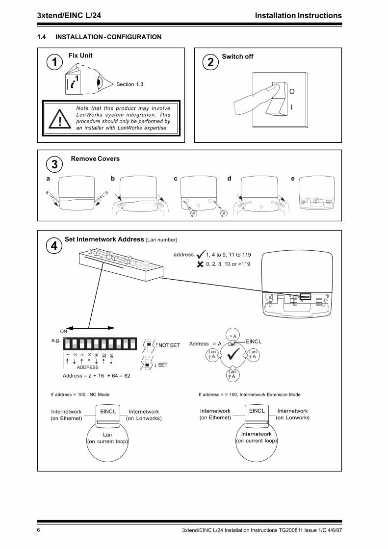
1.4 INSTALLATION - CONFIGURATION
Remove Covers3
1 2 3 4 5 6 7 8 9 10
a b c d e
Fix Unit1
Section 1.3
Switch off2
O
I
1
Note that this product may involveLonWorks system integration. Thisprocedure should only be performed byan installer with LonWorks expertise.
!
ADDRESS
ON
Set Internetwork Address (Lan number)4
SET
NOT SETe.g.
Address = 2 + 16 + 64 = 82
ON= A
EINC LLanLan/= A
Lan/= A
Lan/= A
If address < 100, INC Mode If address = > 100, Internetwork Extension Mode
Address = A
address 1, 4 to 9, 11 to 119
0, 2, 3, 10 or >119
Internetwork(on Ethernet)
Internetwork(on Lonworks)
EINC L
Lan(on current loop)
Internetwork(on Ethernet)
Internetwork(on Lonworks
EINC L
Internetwork(on current loop)
73xtend/EINC L/24 Installation Instructions TG200811 Issue 1/C 4/6/07
Installation Instructions 3xtend/EINC L/24
1 2 3 4 5 6 7 8 9 10
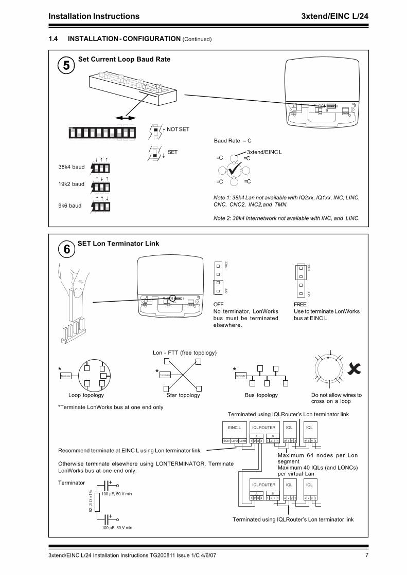
Set Current Loop Baud Rate5
1.4 INSTALLATION - CONFIGURATION (Continued)
� � � � � � � �� � � � � � � �� � � � � � � �
Star topology Bus topologyLoop topology
*Terminate LonWorks bus at one end only
*
LonASCN LonB
EINC L
A
1
IQLROUTER
2 3 4
B
1 2 3 4
IQL
x y
A
1
IQLROUTER
2 3 4
B
1 2 3 4
zw
IQL
x y zw
IQL
x y zw
IQL
x y zw
Recommend terminate at EINC L using Lon terminator link
Otherwise terminate elsewhere using LONTERMINATOR. TerminateLonWorks bus at one end only.
Lon - FTT (free topology)
**
Do not allow wires tocross on a loop
Maximum 64 nodes per LonsegmentMaximum 40 IQLs (and LONCs)per virtual Lan
Terminated using IQLRouter’s Lon terminator link
100 � F, 50 V min
100 � F, 50 V min
Terminator
Terminated using IQLRouter’s Lon terminator link
6 SET Lon Terminator Link
1 2 3 4 5 6 7 8 9 10
���
����
OFFNo terminator, LonWorksbus must be terminatedelsewhere.
FREEUse to terminate LonWorksbus at EINC L
���
����
5
SET
NOT SET
3xtend/EINC L
Baud Rate = C
=C
=C
=C
=C
38k4 baud
Note 1: 38k4 Lan not available with IQ2xx, IQ1xx, INC, LINC,CNC, CNC2, INC2,and TMN.
Note 2: 38k4 Internetwork not available with INC, and LINC.
19k2 baud
9k6 baud
8 3xtend/EINC L/24 Installation Instructions TG200811 Issue 1/C 4/6/07
3xtend/EINC L/24 Installation Instructions
1.4 INSTALLATION - CONFIGURATION (Continued)
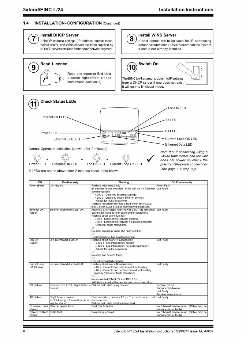
Install DHCP Server7 If the IP address settings (IP address, subnet mask,default router, and WINs server) are to be supplied bya DHCP server install one on the same network segment.
Switch On�
�3
Read Licence9Read and agree to End UserLicence Agreement (theseinstructions Section 2).
10The EINC L will attempt to obtain its IP settingsfrom a DHCP server if one does not existit will go into link/local mode.
Install WINS Server8 If host names are to be used for IP addressingacross a router install a WINS server on the systemif one is not already installed.
1 2 3 4 5 6 7 8 9 10
Check Status LEDs11
Power LED
Ethernet OK LED
Lon OK LED
Current Loop OK LED
RX LED
TX LED
Ethernet Data LEDEthernet Link LED
Power LED Ethernet OK LED Lon OK LED Current Loop OK LED+ + +
Normal Operation Indication (shown after 2 minutes)
If LEDs are not as above after 2 minutes check table below.
LED Continuously Flashing Off ContinuouslyPower (Blue) Unit Healthy Flashing twice repeatedly
IP address is not available, there will be no Ethernetcommunications < 300 s - Obtaining Ethernet settings. > 300 s - Unable to obtain Ethernet settings (Check for faults elsewhere).Flashing repeatedly unit has a fault check other LEDs.If all 3 green LEDs are also flashing-invalid address.
Power FaultUnit Faulty
Ethernet OK(Green)
Ethernet internetwork built OK Flashing alternately with Power LED - No Ethernetconnection found. (Check cable and/or connector.).Flashing about every 12 s for: < 90 s - Ethernet internetwork building. > 90 s - Ethernet internetwork not building properly (Check for faults elsewhere).OrNo other devices at same UDP port number.OrCable/Connector has developed a fault.
Unit Faulty
Lon OK(Green)
Lon internetwork built OK Flashing about every 24 seconds for: < 120 s - Lon internetwork building. > 120 s - Lon internetwork not building properly (Check for faults elsewhere).OrNo other Lon devices found.OrLon not terminated correctly
Unit Faulty
Current LoopOK (Green)
Lon internetwork/Lan built OK Flashing about every 12 seconds for: < 60 s - Current Loop internetwork/Lan building. > 60 s - Current Loop Lan/internetwork not building properly (Check for faults elsewhere).OrNot connected (Check TX and RX LEDs).Will flash intermittentlywhen the unit is communicating.
Unit Faulty
RX (Yellow) Receiver circuit OK, slight flicker =normal.
Flickers fast - data being received. Receiver circuitdisconnected/brokenUnit FaultyReceiver wires shorted
TX (Yellow) Slight flicker - normal.No Flickering - Transmitter circuitmay be shorted.
F l a s h e s a b o u t eve r y 1 2 s - Tra n s m i t t e r c i r c u i tdisconnected.Flickers fast - data is being transmitted.
Unit Faulty
E t h e r n e t L i n k(Green)
Ethernet device found Fault (Cable faulty). No Ethernet device found. (Cable may bedisconnected or faulty)
E therne t Data(Yellow)
Cable fault Data being received. No Ethernet device found. (Cable may bedisconnected or faulty)
Note that if connecting using a24Vac transformer and the unitdoes not power up check thepolarity of the power connections(see page 1-4 step (6)).
93xtend/EINC L/24 Installation Instructions TG200811 Issue 1/C 4/6/07
Installation Instructions 3xtend/EINC L/24
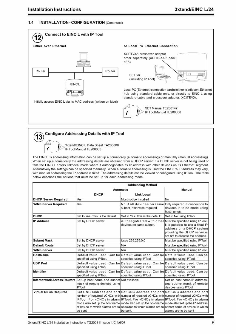
12 Connect to EINC L with IP Tool
SET Manual TE200147IP Tool Manual TE200638
Router
EINC L
Router
Either over Ethernet or Local PC Ethernet Connection
XCITE/XA crossover adaptororder separately (XCITE/XA/5 packof 5)
SET v6(including IP Tool)
Local PC (Ethernet) connection can be either to adjacent Ethernethub using standard cable only, or directly to EINC L usingstandard cable and crossover adaptor, XCITE/XA.
Initially access EINC L via its MAC address (written on label)
Configure Addressing Details with IP Tool133xtend/EINC L Data Sheet TA200800IP Tool Manual TE200638
The EINC L’s addressing information can be set up automatically (automatic addressing) or manually (manual addressing).When set up automatically the addressing details are obtained from a DHCP server, if a DHCP server is not being used orfails the EINC L enters link/local mode where it autonegotiates its IP address with other devices on its Ethernet segment.Alternatively the settings can be specified manually. When automatic addressing is used the EINC L’s IP address may vary,with manual addressing the IP address is fixed. The addressing details can be viewed or configured using IPTool. The tablebelow describes the options that must be set up for each addressing mode.
Addressing MethodAutomatic Manual
DHCP Link/LocalDHCP Server Required Yes Must not be installed NoWINS Server Required Yes No i f a l l d e vi c e s o n s a me
subnet, otherwise required.Only required if connection todevices is to be made usinghost names.
DHCP Set to Yes. This is the default. Set to Yes. This is the default. Set to No using IPToolIP Address Set by DHCP server A utonego ti a ted wi th o the r
devices on same subnet.Must be specified using IPTool.It is possible to use a fixed IPaddress on a DHCP systemproviding the DHCP server isset not to allocate the address.
Subnet Mask Set by DHCP server Uses 255.255.0.0 Must be specified using IPToolDefault Router Set by DHCP server N/A Must be specified using IPToolWINS Server Set by DHCP server N/A Must be specified using IPToolHostName Default va lue used. Can be
specified using IPTool.Default value used. Can bespecified using IPTool.
Default value used. Can bespecified using IPTool.
UDP Port Default va lue used. Can bespecified using IPTool.
Default value used. Can bespecified using IPTool.
Default value used. Can bespecified using IPTool.
Identifier Default va lue used. Can bespecified using IPTool.
Default value used. Can bespecified using IPTool.
Default value used. Can bespecified using IPTool.
Internetwork Across Routers Set up host name and subnetmask of remote devices usingIPTool.
Not available Set up host name/IP address,and subnet mask of remotedevices using IPTool.
Virtual CNCs Required S et C NC address and portnumber of required vCNCs withIPToo l. For vCNCs in a larmmode also set up the host nameof device to which alarms are tobe sent.
Set CNC address and portnumber of required vCNCs withIPTool. For vCNCs in alarmmode also set up the host nameof device to which alarms are tobe sent.
Set CNC address and portnumber of required vCNCs withIPTool. For vCNCs in alarmmode also set up the IP addressof host name of device to whichalarms are to be sent
1.4 INSTALLATION - CONFIGURATION (Continued)

10 3xtend/EINC L/24 Installation Instructions TG200811 Issue 1/C 4/6/07
3xtend/EINC L/24 Installation Instructions
Configure Addressing Details with IP Tool (Continued)133xtend/EINC L Data Sheet TA200800IP Tool Manual TE200638
1.4 INSTALLATION - CONFIGURATION (Continued)
The table below describes the addressing parameters that need to be set up.
Parameter Description When to changeAddressModule
Identifier A 40 -charac te r labe l used to i dent i fy the Lan. It de faults toTREND_xx_yy_zz. Where xx, yy, and zz are the last 3 groups of numbersin the MAC address.Range = 40 alphanumeric characters - not /\({;?* characters
When default is not suitable.
IPNetworkModule
Default Router The IP address of the router to which messages are sent i f thedestination address is not on the local subnet. It should be set to the IPaddress of a router on the same subnet as the EINC L. It must bespecified if the EINC L is to build an internetwork that spans routers, orif one of the virtual CNCs is to be used by a PC connected to an Ethernetsubnet the other side of a router.When automatic addressing is specified it is obtained from a DHCPserver. If there no DHCP server or it is not operating it is not set.If manual addressing is selected it must be manually defined, in this caseit defaults to 0.0.0.0.Range = 0.0.0.0 to 255.255.255.255
When manual addressing isbeing used.
DHCP Specifies whether automatic or manual addressing is used.When automatic addressing is specified the EINC L's IP address,subnet mask, default router, and WINS server parameters are obtainedfrom a DHCP server. If there no DHCP server or it is not operating theIP address is autonegotiated with the other devices on the same subnet,and the IP subnet mask is set to 255.255.0.0If manual addressing is selected the EINC L's IP address, subnet mask,default router, and WINS server parameters must be manually defined.Range = Yes or No, Yes = DHCP used, Default = Yes.
When addressing mode is tobe changed.Manual addressing can beus e d o n a s ys t e m w i t h aDHCP server provideg theEINC L's address is outsidethe range assigned by theserver
Host Name (read/only) A 15-character string that is registered with the network nameserver for connecting by name rather than IP addresIt defaults to TREND_xx_yy_zz. Where xx, yy, and zz are the last 3 groupsof numbers in the MAC address.Range = 15 alphanumeric characters - not /\({;?* characters
When default is not suitable.
IP Address (read/write) The IP address of the EINC L. The IP address for eachdevice on the Ethernet network must be unique to avoid addressclashes.When automatic addressing is specified it is obtained from a DHCPserver. If there no DHCP server or it is not operating it is autonegotiatedwith other devies on the same subnet.If manual addressing is selected it must be manually defined, in this caseit defaults to 0.0.0.0.Range = 0.0.0.0 to 255.255.255.255
When manual addressing isbeing used.
WINS Server (read/write) Specifies the IP address of the WINS Server.When automatic addressing is specified it is obtained from a DHCPserver. If there no DHCP server or it is not set.If manual addressing is selected it must be manually defined, in this caseit defaults to 0.0.0.0.Range = 0.0.0.0 to 255.255.255.255
When manual addressing isbeing used, and connection todevices using hostnames isrequired.
Subnet Mask (read/write) The subnet mask of the EINC L The subnet mask must bethe same for all devices not separated by routers that are to build Lansor an internetwork. This ensures that they are on the same subnet.When automatic addressing is specified it is obtained from a DHCPserver. If there no DHCP server it is set to 0.0.0.0.If manual addressing is selected it must be manually defined, in this caseit defaults to255.255.255.0.Range = 0.0.0.0 to 255.255.255.255
When manual addressing isbeing used.
UDP Port (read/write)The UDP (User Datagram Protocol) port used by the EINCL to communicate with other IQ system devices over the Ethernetnetwork. All devices used to create an internetwork must use same port.Defaults to 57612.Range = 0 to 65535
When default is not suitablee.g port already being used ormultiple internetworks (sites)required on the same subnet.

113xtend/EINC L/24 Installation Instructions TG200811 Issue 1/C 4/6/07
Installation Instructions 3xtend/EINC L/24
Configure Addressing Details with IP Tool (Continued)13
1.4 INSTALLATION - CONFIGURATION (Continued)
Parameter Description When to changeRemoteEINCModules
IP Address (read/write) The IP address/host name of the remote device on Ethernet.The host name or IP address of the remote device on Ethernet.Range = 0.0.0.0 to 255.255.255.255. Default=0.0.0.0
If internetwork is to be bui ltacross routers.
Subnet mask (read/write) The subnet mask for the remote device.Range = 0.0.0.0 to255.255.255.255 Default=0.0.0.0
At least two devices from each each subnet should be specifed. For increased reliability details of additional devicesshould be specified. If automatic addressing is being used the devices must be specified using hostnames, and if manualaddressing is being used the list should contain the devices with the lowest IP addresses. The table must be placed inall devices on the network.
VirtualCNCModules
Alarm IPAddress
The host name or IP address of the alarm target supervisor that isconnected to the Ethernet network if operating in alarm mode. Settingthis up switches the virtual CNC into alarm mode, and prevents the virtualCNC being used as a CNC by a supervisor. 0 will switch the virtual CNCback into supervisor mode. Default=Unused
If the virtual CNC is to be usedto send alarms to a supervisorover Ethernet.
CNC Address The device address of the virtual CNC on EINC L’s Lan. It is set tounused by default, and the virtual CNC will not operate until its addressis set up. It can be set to any valid address (1 to 119 excludingaddresses 2, 3, and 10). 0 will disable the virtual CNC.
If the virtual CNC is to be used.
Port Address The TCP port used by the virtual CNC. It is set unused by default andthen defaults to 10000 plus the cnc address when the cnc address isset up, but can subsequently be changed.Range = 1 to 32767.
If the virtual CNC is to be used.
14 a Enter configuration mode using SET. The top levelprompt will be displayed as below.
b Configure the optional settings the relevant uppercase letter and pressing ENTER. If a value has beenchanged X+ENTER will confirm it and return to thetop menu, whereas Q+ENTER will quit and returnwith the value unchanged. The table below describesthe settings.
SET Manual TE200147
Configure Optional Settings Using SET
Note that it may be necessary to set up a virtual CNC in theEINC L if one is not available elsewhere on the network.
3xtend/EINC L Data Sheet TA200800
Parameter DescriptionAddressModule
Lan AlarmAddress
The alarm target device address for alarms generated by the current loop network when it is operatingas a Lan. It can be set to any valid address (1 to 119 excluding addresses 2, 3, and 10). 0 stops thealarms being transmitted.
Lan AlarmLan
The target Lan number for alarms generated by the current loop network when it is operating as a Lan.It can be set to any valid address (1 to 119 excluding addresses 2, 3, and 10). 0 stops the alarms beingtransmitted.
AlarmLanguage
The language used for the network alarms. 0=English, 1=Spanish, 2=Finnish, 3=Swedish, 4=Norwegian,5=Danish, 6=German, 7=Italian, 8=Portuguese, 9=French.
InternetworkAlarmAddress
The alarm target device address for internetwork alarms. It can be set to any valid address (1 to 119excluding addresses 2, 3, and 10). 0 stops the alarms being transmitted.
InternetworkAlarm Lan
The alarm target Lan number for internetwork alarms. It can be set to any valid address (1 to 119 excludingaddresses 2, 3, and 10). 0 stops the alarms being transmitted.
DisablevCNC AliveAlarms
Enables/disables device on-line, and device dead alarms generated by virtual CNCs. Range=Yes or No,Yes = alarms disabled. Default = No.
RemoteDevices
SendRemoteBroadcasts
Specifies whether remote broadcast messages or directed messages are used to build the internetworkacross routers.If set to use broadcast messages (Yes) the messages used to build the internetwork across routerswill be sent to the default router requesting a broadcast message to all devices on the remotedevice’s subnet as well as the remote device specified in the module.If set not to use broadcast messages (No) the messages used to build the internetwork across routerswill only be sent (by direct messaging) to the device specified in the module.This option should only be turned off if the routers have remote broadcast messaging disabled.If broadcasting is turned off, details of as many device’s as possible from each subnet should be enteredin the remote devices table to enable the internetwork to be built in the event of a failure.

12 3xtend/EINC L/24 Installation Instructions TG200811 Issue 1/C 4/6/07
3xtend/EINC L/24 Installation Instructions
17 Replace Covers
a b c d
1.4 INSTALLATION - CONFIGURATION (Continued)
14 Configure Optional Settings Using SET (Continued)
Note that if required the parameters configured using IP Tool can also be configured in the same way.
Write on Label15Tear off Label Strip16
XTEND -400007096� � � � � � �
�
� � � � � 00.10.70.00.UD.BB
� � �
S/No:
� � � � � � � Location
� � � � � 00.10.70.00.UD.BB
S/No:Q3B____X73010003
� � � � � � �
� � � � � 00.10.70.00.UD.BB S/No:Q3B____X73010003
� � � � � � � Location �
� � � � � 00.10.70.00.UD.BB
� � �
S/No:Q3B____X73010003
� � � � � � � Location
� � � � � 00.10.70.00.UD.BB
S/No:Q3B____X73010003XTND -400007096
� � � � � � �
� � � � � � �
recommendede.g. location/identifier
IP Address, Location, Lan, address
�
� � � � � 00.10.70.00.UD.BB
� � �
S/No:Q3B____X73010003
� � � � � � � Location
� � � � � 00.10.70.00.UD.BB
S/No:Q3B____X73010003XTND -400007096
� � � � � � �
� � � � � � �
Parameter DescriptionTimeModule
Time The date and time (note note battery backed)
UpdateRemoteDevices
Copy yourremote EINClist to otherEINCs (Y/N)
Copies the remote Eincs list to local subnet and all subnets with EINC/Ls and EINC in list
UserModules
PIN The 4-digit number that must be entered by the user to log on from a display, or must be sent by atool/supervisor to authorise a change.
18 Check Virtual CNCs Virtual CNCs in Alarm Mode
� � � � � � � �
CNCBCNCA
EINC L
CNCDCNCC
SET, or 963using permanent connection
CNC in Supervisor mode
CNCFCNCE CNCHCNCG
Virtual CNCs in Supervisor Mode
� � � � � � � �
CNCBCNCA
EINC L
CNCDCNCC
963using temporary connection
CNC in Alarm mode
CNCFCNCE CNCHCNCG
Alarm from system sent to VCNC

133xtend/EINC L/24 Installation Instructions TG200811 Issue 1/C 4/6/07
Installation Instructions 3xtend/EINC L/24
19 Check Communications
If address <100
� �
� � � � � � � � � � � � � � � � �
� �
� � � � � � � � � � � � � � � � �
� � � �
� � � � � � � � � � �
� � � � � � � � � � � � �
� � � � � � � � � � �
� � � � � � �
EINC
� � �
4 5 6
27 8 9
310 11 12
4
13 14 15
516 17 18
619 20 21
7
22 23 24
825 26 27
928 29 30
10+ 0+ 0 + 0 + 0 + 0 + 0+ 0+ 0+ 0
1 2 3
1+ 0
0 V24 V
24 V 34 35 36
12
37 38 39
13
40 41 42
14A
31 32 33P
11
43 44 45
15
46 47 48
16100-240 V
OK RXP 0 P 0 P 0P 0 P 0 P 0
OK
Tx Rx
230 V1 2 3 4 5 6 83 4 5
7 9 10 1124 V 24V
AC24VAC
24VAC
� !
� �
� � � � � � � � � � � � � � � � �
� �
� � � � � � � � � � � � � � � � �
� � � �
� � � � � � � � � � �
� � � � � � � � � � � � �
� � � � � � � � � � �
� � � � � � �
EINC
� � �
4 5 6
27 8 9
310 11 12
413 14 15
5
16 17 18
619 20 21
7
22 23 24
825 26 27
928 29 30
10+ 0+ 0 + 0 + 0 + 0 + 0+ 0+ 0+ 0
1 2 3
1+ 0
0 V24 V
24 V 34 35 36
12
37 38 39
13
40 41 42
14A
31 32 33P
11
43 44 45
15
46 47 48
16100-240 V
OK RXP 0 P 0 P 0P 0 P 0 P 0
OK
Tx Rx
230 V1 2 3 4 5 6 83 4 5
7 9 10 1124 V 24V
AC24VAC
24VAC
� !
If address =>100
� �
� � � � � � � � � � � � � � � � �
� � � � � � � � � � �
� � � � � � � � � � � � � � � � �
� � � �
� � � � � � � � � � �
� � � � � � � � � � � � �
� � � � � � � � � � �
� � � � � � �
EINC
� � �
4 5 6
27 8 9
310 11 12
4
13 14 15
5
16 17 18
6
19 20 21
7
22 23 24
825 26 27
928 29 30
10+ 0+ 0 + 0 + 0 + 0 + 0+ 0+ 0+ 0
1 2 3
1+ 0
0 V24 V
24 V 34 35 36
12
37 38 39
13
40 41 42
14A
31 32 33P
11
43 44 45
15
46 47 48
16100-240 V
OK RXP 0 P 0 P 0P 0 P 0 P 0
OK
Tx Rx
230 V1 2 3 4 5 6 83 4 5
7 9 10 1124 V 24V
AC24VAC
24VAC
� !
� �
� � � � � � � � � � � � � � � � �
� �
Lan
(on current loop)
Internetwork
(on current loop)
EINC L
Internetwork
(on Ethernet)
Internetwork
(on LON)
EINC
EINC
4 5 6
27 8 97 8 9
310 11 12
413 14 15
516 17 1816 17 18
619 20 2119 20 21
722 23 24
825 26 2725 26 27
928 29 3028 29 30
10+ 0+ 0 + 0 + 0+ 0 + 0 + 0+ 0+ 0+ 0+ 0
1 2 3
1+ 0+ 0
0V24V
24V 34 35 36
12
37 38 39
13
40 41 4240 41 42
14A
31 32 33P
11
43 44 4543 44 45
15
46 47 48
16100-240 V100-240 V
OK RXP 0 P 0P 0 P 0P 0P 0 P 0P 0 P 0P 0
OK
Tx Rx
230 V1 2 3 4 5 6 83 4 5
7 9 10 1124V 24V
AC24VAC
24VAC
IQL
Lan
(on current loop)
INC
� �
� � � � � � � � � � � � � � � � �
� � � � � � � � � � �
� � � � � � � � � � � � � � � � �
� � � � � � � � � � � � � � �
� � � � � � � � � � � � �
� � � � � � � � � � �
� � � � � � �
EINC
� � �
4 5 6
27 8 9
310 11 12
4
13 14 15
516 17 18
619 20 21
7
22 23 24
825 26 27
928 29 30
10+ 0+ 0 + 0 + 0 + 0 + 0+ 0+ 0+ 0
1 2 3
1+ 0
0 V24 V
24 V 34 35 36
12
37 38 39
13
40 41 42
14A
31 32 33P
11
43 44 45
15
46 47 48
16100-240 V
OK RXP 0 P 0 P 0P 0 P 0 P 0
OK
Tx Rx
230 V1 2 3 4 5 6 83 4 5
7 9 10 1124 V 24V
AC24VAC
24VAC
� !
� �
� � � � � � � � � � � � � � � � �
� �
1.4 INSTALLATION - CONFIGURATION (Continued)

14 3xtend/EINC L/24 Installation Instructions TG200811 Issue 1/C 4/6/07
3xtend/EINC L/24 Installation Instructions
2 END USER LICENCE AGREEMENTEULA Terms
• You have acquired a 3xtend/EINC L (“Device”) that includes software licensed by Trend Control Systems Ltd from one or moresoftware licensors (“Trend Control Systems Ltd Software Suppliers”). Such software products, as well as associated mediaprinted materials and “online” or electronic documentation (“SOFTWARE”) are protected by international intellectual propertylaws and treaties. The SOFTWARE is licensed, not sold. All rights reserved.”
• IF YOU DO NOT AGREE TO THIS END USER LICENSE AGREEMENT (“EULA”), DO NOT USE THE DEVICE OR COPY THESOFTWARE. INSTEAD, PROMPTLY CONTACT TREND CONTROL SYSTEMS LTD FOR INSTRUCTIONS ON RETURN OF THEUNUSED DEVICE(S) FOR A REFUND. ANY USE OF THE SOFTWARE INCLUDING BUT NOT LIMITED TO USE ON THE DEVICEWILL CONSTITUTE YOUR AGREEMENT TO THE EULA (OR RATIFICATION OF ANY PREVIOUS CONSENT).
• GRANT OF SOFTWARE LICENSE. This EULA grants you the following license:
• You may use the SOFTWARE only on the DEVICE
• NOT FAULT TOLERANT. THE SOFTWARE IS NOT FAULT TOLERANT. TREND CONTROL SYSTEMS LTD HASINDEPENDENTLY DETERMINED HOW TO USE THE SOFTWARE IN THE DEVICE, AND TREND CONTROL SYSTEMS LTD’SSOFTWARE SUPPLIERS HAS RELIED UPON TREND CONTROL SYSTEMS LTD TO CONDUCT SUFFICIENT TESTING TODETERMINE THAT THE SOFTWARE IS SUITABLE FOR SUCH USE.
• NO WARRANTIES FOR THE SOFTWARE. THE SOFTWARE is provided “AS IS” and with all faults. THE ENTIRE RISKAS TO SATISFACTORY QUALITY, PERFORMANCE, ACCURACY, AND EFFORT (INCLUDING LACK OF NEGLIGENCE)IS WITH YOU. ALSO, THERE IS NO WARRANTY AGAINST INTERFERENCE WITH YOUR ENJOYMENT OF THE SOFTWAREOR AGAINST INFRINGEMENT. IF YOU HAVE RECEIVED ANY WARRANTIES REGARDING THE DEVICE OR THE SOFTWARE,THOSE WARRANTIES DO NOT ORIGINATE FROM, AND ARE NOT BINDING ON, TREND CONTROL SYSTEMS LTD’SSOFTWARE SUPPLIERS.
• Note on Java Support. The SOFTWARE may contain support for programs written in Java. Java technology is not faulttolerant and is not designed, manufactured, or intended for use or resale as online control equipment in hazardousenvironments requiring fail-safe performance, such as in the operation of nuclear facilities, aircraft navigation orcommunication systems, air traffic control, direct life support machines, or weapons systems, in which the failure of Javatechnology could lead directly to death, personal injury, or severe physical or environmental damage. Sun Microsystems,Inc. has contractually obligated Trend Control Systems Ltd’s software suppliers to make this disclaimer.
• No Liability for Certain Damages. EXCEPT AS PROHIBITED BY LAW, TREND CONTROL SYSTEMS LTD’S SOFTWARESUPPLIERS SHALL HAVE NO LIABILITY FOR ANY INDIRECT, SPECIAL, CONSEQUENTIAL OR INCIDENTAL DAMAGESARISING FROM OR IN CONNECTION WITH THE USE OR PERFORMANCE OF THE SOFTWARE. THIS LIMITATION SHALLAPPLY EVEN IF ANY REMEDY FAILS OF ITS ESSENTIAL PURPOSE. IN NO EVENT SHALL TREND CONTROL SYSTEMSLTD’S SOFTWARE SUPPLIERS BE LIABLE FOR ANY AMOUNT IN EXCESS OF U.S. TWO HUNDRED FIFTY DOLLARS(U.S.$250.00).
• Limitations on Reverse Engineering, Decompilation, and Disassembly. You may not reverse engineer, decompile,or disassemble the SOFTWARE, except and only to the extent that such activity is expressly permitted by applicable lawnotwithstanding this limitation.
• SOFTWARE TRANSFER ALLOWED BUT WITH RESTRICTIONS. You may permanently transfer rights under this EULAonly as part of a permanent sale or transfer of the Device, and only if the recipient agrees to this EULA. If the SOFTWAREis an upgrade, any transfer must also include all prior versions of the SOFTWARE.

153xtend/EINC L/24 Installation Instructions TG200811 Issue 1/C 4/6/07
Installation Instructions 3xtend/EINC L/24
WEEE Directive :
At the end of their useful life the packaging andproduct should be disposed of via a suitablerecycling centre.
Do not dispose of with normal household waste. Do not burn.
3 DISPOSAL
16 3xtend/EINC L/24 Installation Instructions TG200811 Issue 1/C 4/6/07
3xtend/EINC L/24 Installation Instructions
Manufactured for and on behalf of the Environmental and Combustion Controls Division of Honeywell Technologies Sàrl, Ecublens, Routedu Bois 37,Switzerland by its Authorized Representative.
Trend Control Systems Ltd reserves the right to revise this publication from time to time and make changes to the content hereofwithout obligation to notify any person of such revisions or changes.
Trend Control Systems LimitedP.O. Box 34, Horsham, West Sussex, RH12 2YF, UK. Tel:+44 (0)1403 211888 Fax:+44 (0)1403 241608 www. trend-controls.comTrend Controls Systems USA6670 185th Avenue NE, Redmond, Washington 98052, USA. Tel: (425)897-3900, Fax: (425)869-8445 www. trend-controls.com