i/q waveform file conversion for use with precise ... · for use with precise broadcast signal...
TRANSCRIPT

I/Q Waveform File Conversion for Use with Precise Broadcast Signal Generators Application Note
Products:
| R&SIQ Converter / R&SIQ Stream Extractor
| R&SBTC / R&SCLG / R&SSLG / R&SSFU / R&SSFE / R&SSFE100
I/Q waveform files contain the digital com-
plex sample values of a radio signal. They
can be synthetically computer-calculated
for generating precisely defined contents,
or they can represent the recording of a
received live signal.
The structure of these files has never
been standardized, which is why so many
different formats are in use today.
R&SIQ Converter and R&SIQ Stream
Extractor are programs that quickly and
conveniently convert the contents of I/Q
waveform files of nearly any structure into
the I/Q format used by the R&SBTC,
R&SCLG, R&SSLG, R&SSFU,
R&SSFE and R&SSFE100 signal gen-
erators. This makes it possible for the sig-
nal generators to use their integrated ARB
function to generate precise RF signals
from nearly any I/Q waveform file.
I/Q W
avef
orm
File
Con
vers
ion
for
Use
with
Pre
cise
Bro
adca
st S
igna
l Gene
rato
rs
Mar
ius
Sch
ippe
r
11-2
013-
7BM
79_2
E

Table of Contents
7BM79_2E Rohde & Schwarz I/Q Waveform File Conversion for Use with Precise Broadcast Signal Generators 2
Table of Contents
1 Overview ................................................................................. 4
1.1 I/Q Waveform Files ....................................................................................... 4
1.2 R&S IQ Converter ......................................................................................... 4
1.3 R&S IQ Stream Extractor ............................................................................. 4
1.4 Supported Broadcast Signal Generators ................................................... 5
2 R&S IQ Converter ................................................................... 6
2.1 Scope of Functions ...................................................................................... 6
2.1.1 Supported Formats ...................................................................................... 6
2.1.2 Automatic Metadata Extraction ................................................................... 6
2.1.3 Support for Uninterrupted Playback .......................................................... 7
2.1.4 Signal Processing ........................................................................................ 7
2.1.5 Batch Processing Mode ............................................................................... 8
2.2 System Requirements .................................................................................. 8
2.3 Installation ..................................................................................................... 8
2.4 Operation ....................................................................................................... 9
2.4.1 User Interface................................................................................................ 9
2.4.2 Metadata Analysis ......................................................................................14
2.4.3 IQ Analysis ..................................................................................................16
2.4.4 Signal Processing ......................................................................................20
3 R&S IQ Stream Extractor ..................................................... 22
3.1 Overview ......................................................................................................22
3.2 Packet Analysis ..........................................................................................24
4 Application Example ............................................................ 27
4.1 R&S IQ Stream Extractor ...........................................................................27
4.2 R&S IQ Converter .......................................................................................34
5 Frequently Asked Questions ............................................... 40
5.1 General ........................................................................................................40
5.2 R&S IQ Converter .......................................................................................40
5.2.1 Analysis .......................................................................................................40
5.2.2 Conversion ..................................................................................................41

Table of Contents
7BM79_2E Rohde & Schwarz I/Q Waveform File Conversion for Use with Precise Broadcast Signal Generators 3
6 References ............................................................................ 43
7 Additional Information ......................................................... 43
8 Ordering Information ........................................................... 44
The following abbreviations are used throughout this document:
R&SXYZ is abbreviated as R&S XYZ.

Overview
I/Q Waveform Files
7BM79_2E Rohde & Schwarz I/Q Waveform File Conversion for Use with Precise Broadcast Signal Generators 4
1 Overview This application note describes the two programs, R&S IQ Converter and R&S IQ
Stream Extractor, which can be used to convert nearly any I/Q waveform file into the
proprietary format used by the R&S BTC, R&S CLG, R&S SLG, R&S SFU, R&S SFE
and R&S SFE100 signal generators.
This chapter describes the individual elements of the application. Chapters 2 and 3
explain how to use the two programs. Finally, to make getting started with the pro-
grams easier, chapter 4 provides an application example and chapter 5 includes a list
of frequently asked questions.
1.1 I/Q Waveform Files
I/Q waveform files contain the digital complex sample values of a radio signal. They
can be synthetically computer-calculated for generating precisely defined contents.
Possible applications include the evaluation of new broadcast standards or the genera-
tion of specific interfering signals.
I/Q sample values can also originate from a recording of a received live signal, and can
then be used as a practical test for receivers under reproducible laboratory conditions.
The structure of these files has never been standardized, which is why so many differ-
ent formats are in use today.
1.2 R&S IQ Converter
R&S IQ Converter is a program that converts the contents of nearly any non-packet-
oriented I/Q waveform file quickly and conveniently into the proprietary file format used
by the R&S BTC, R&S CLG, R&S SLG, R&S SFU, R&S SFE and R&S SFE100 signal
generators.
Even files with an initially unknown structure can be converted using the application's
powerful analysis functions.
Integrated signal processing modules, such as digital filters and resamplers, round out
the scope of functions.
1.3 R&S IQ Stream Extractor
R&S IQ Stream Extractor is available for packet-oriented I/Q waveform files of any
structure. This program splits the individually received, independent I/Q streams into
separate output files and simultaneously strips away the packet structure so that the
individual signals can be processed using R&S IQ Converter.

Overview
Supported Broadcast Signal Generators
7BM79_2E Rohde & Schwarz I/Q Waveform File Conversion for Use with Precise Broadcast Signal Generators 5
1.4 Supported Broadcast Signal Generators
R&S BTC R&S CLG R&S SFU R&S SFE
R&S SLG R&S SFE100
General
Frequency range 100 kHz to 6 GHz 47 MHz to 1002 MHz
100 kHz to 3 GHz 100 kHz to 2700 MHz 250 MHz to 3000 MHz
Level –120 dBm to 18 dBm up to -14 dBm per carrier –120 dBm to 19 dBm –110 dBm to 27 dBm
I/Q waveform generator
Independent generators
8 per RF path (=8x2) 4 1 1
Memory 1 Gsample per RF path 8 Msample each
1 Gsample 256 Msample 64 Msample (shared)
Useful signal
bandwidth
up to 125 MHz
per RF path
8 MHz each 40 MHz 40 MHz
140 MHz (shared)
Interferer
Management yes yes yes no
Digital I/Q output yes no yes no
Additional features
Fading simulator up to 4x40 paths no up to 2x20 paths up to 12 paths
no
Phase / impulsive
noise generator yes
no yes no
yes
AWGN noise
generator yes
no yes yes
yes
Remote control GPIB, LAN, USB LAN GPIB, LAN LAN
The Interferer Management function provided by R&S BTC, R&S CLG, R&S SLG or
R&S SFU even allows the reconstructed I/Q signals to be combined with another
broadcast signal generated in realtime. Depending on its position in the spectrum, the
I/Q signal will then act as a co-channel or adjacent-channel interferer [1].

R&S IQ Converter
Scope of Functions
7BM79_2E Rohde & Schwarz I/Q Waveform File Conversion for Use with Precise Broadcast Signal Generators 6
2 R&S IQ Converter
2.1 Scope of Functions
2.1.1 Supported Formats
The software supports any format displaying a combination of the following elements:
File structure
I and Q data together in one file or in two separate files
Metadata
None / header only / trailer only / header and trailer
Text / binary (Little or Big Endian)
I/Q sample values
Text: integer / floating point / hexadecimal
or
Binary (Little or Big Endian):
o Floating point (32 bit / 64 bit)
o Integer (8 / 16 / 32 / 64 bit, signed or unsigned)
Sequence: IQ / QI / I only (Q is set to 0) / I only (Q is set to = I)
Skip up to 10 markers before the I or Q sample value
Powerful analysis functions make it possible to identify the format elements used in an
initially unknown file structure.
2.1.2 Automatic Metadata Extraction
The Rohde & Schwarz file format includes not only the central I/Q sample values but
also a user-specific comment field and the sampling frequency.
The software can determine these two parameters automatically from the source file
metadata (header or trailer).

R&S IQ Converter
Scope of Functions
7BM79_2E Rohde & Schwarz I/Q Waveform File Conversion for Use with Precise Broadcast Signal Generators 7
2.1.3 Support for Uninterrupted Playback
Because of their short runtime, I/Q waveform files are played back in an endless loop
on the replay generators. Therefore, the end of the I/Q waveform should precisely
match its start to prevent any discontinuity and the associated interference spectrum at
the transition point.
To allow this, the software can be programmed to convert only a specific interval. An
I/Q waveform preview of the transition from the end of an interval back to its start
makes it easy to determine the optimum interval boundary that will result in the least
amount of discontinuity.
2.1.4 Signal Processing
During the actual conversion, a number of interesting I/Q characteristics can be influ-
enced in parallel:
Scale factor
Rohde & Schwarz waveform generators process integral I/Q sample values in the
range of ±32767.
If the value range of the waveform to be converted is larger, then a scale factor of < 1
should be selected to prevent "clipping" (i.e., non-linear rounding up or down).
If the value range is smaller, on the other hand, a scale factor of > 1 is recommended
to keep the quantization noise as low as possible.
The scale factor does not influence the performance of the last signal output by the
Rohde & Schwarz waveform generator.
Although the optimum scale factor is determined automatically, manually defining the
scale factor can cut the conversion time in half.
DC offset
The most efficient utilization of the value range on the Rohde & Schwarz waveform
generators using the scale factor is possible only with a zero-mean input signal.
However, unsigned integer input formats always result in a positive RMS value, which
can be compensated for using the "DC offset" parameter.
Spectrum mirror
The I/Q data spectrum can be mirrored as needed. This corresponds to an inversion of
the Q sample values.
Spectrum selection
Any segment of the I/Q spectrum can be shifted in order to position it symmetrically at
the 0 Hz mark so that the remaining segments can then be suppressed using a low-
pass filter. This is particularly useful when the input waveform includes multiple chan-
nels.
Sample rate reduction
If the input spectrum is not fully utilized up to the Nyquist frequency, this is because the
I/Q sample values have been generated at a higher sample frequency than necessary.
Since higher sample frequencies require higher data rates and thus shorter runtimes,
the software makes it possible to reduce the sample rate by means of resampling as
part of the spectrum selection process described above.

R&S IQ Converter
System Requirements
7BM79_2E Rohde & Schwarz I/Q Waveform File Conversion for Use with Precise Broadcast Signal Generators 8
2.1.5 Batch Processing Mode
Any number of input files can be automatically converted in sequence.
2.2 System Requirements
The program requires a PC running Microsoft®
Windows XP/ Vista / 7 (32 bit or 64 bit)
and approximately 20 Mbyte disk space.
In addition, depending on size, each I/Q waveform file will require up to 4 Gbyte free
disk space to store the conversion results.
The minimum monitor resolution is 1024 x 768; however, 1280 x 1024 pixels or more
are recommended for better legibility.
2.3 Installation
The program is installed by launching the R&S IQ Converter Setup_X_X_X.exe" file,
where the three "X" placeholders represent the current version. This file can be down-
loaded at no cost from the download page of this application note.
If a previous version of the program is already present on the PC, it will be uninstalled
automatically during the installation process. Any user-defined configuration files will
be retained and can be used in the updated software.

R&S IQ Converter
Operation
7BM79_2E Rohde & Schwarz I/Q Waveform File Conversion for Use with Precise Broadcast Signal Generators 9
2.4 Operation
The user interface always displays the currently active configuration along the right-
hand side of the screen. This configuration defines the conversion scheme that will be
used to convert the I/Q input files. The number and flexibility of the individual configura-
tion parameters make it possible to support the structure of many I/Q input files. Four
different views are available on the left-hand side of the screen, although the Files view
is always active whenever the program is launched. In this Files view, the integrated
File Browser can be used to add I/Q waveform files to the job list for conversion. If a
configuration already exists for the current input format, it is to be selected. Otherwise,
the various analysis views (Metadata Analysis, IQ Analysis and Signal Processing) can
be used to create a matching configuration, which can then be saved for later use. Fi-
nally, the "Start conversion jobs" button starts automatic processing of the job list.
2.4.1 User Interface
Fig. 1: Files view.
2.
4. 5. 6.
7.
1. 8. 9.
10.
11.
12.
3.

R&S IQ Converter
Operation
7BM79_2E Rohde & Schwarz I/Q Waveform File Conversion for Use with Precise Broadcast Signal Generators 10
This section uses Fig. 1 to describe the options available in the Files view on the left-
hand side of the screen, as well as the static controls on the right-hand side:
1. View tabs
Used to switch between the Files view and the three different analysis views (Metadata
Analysis, IQ Analysis and Signal Processing) on the left-hand side of the screen.
2. File Browser
Serves to select the files to be converted. Double-clicking a file adds it directly to the
job list (see 7). Alternatively, multiple files can be highlighted and then added to the job
list by clicking the "Add IQ" button (see 4).
3. "Refresh" button
Updates the File Browser.
4. "Add IQ" or "Add I" / "Add Q" button
Moves the currently selected files in the File Browser to the job list. The subsequent
display depends on the file structure defined in the configuration on the right-hand side
of the screen:
"Combined IQ (1 File)" "Separate I/Q (2 Files)"
5. Default Output Directory
For every new job in the list, the storage location and name of the output file are auto-
matically defined during insertion based on the storage location defined here. Changes
will not affect jobs already present in the list.
6. Overwrite Protection
If enabled, existing output files will not be overwritten.
7. Conversion jobs (job list)
This area lists the individual conversion jobs and their status:
Fig. 2: Job list.
a) b) c)
d)
d)

R&S IQ Converter
Operation
7BM79_2E Rohde & Schwarz I/Q Waveform File Conversion for Use with Precise Broadcast Signal Generators 11
7a) Job: Delete
Clear this checkbox to remove the job from the list.
7b) Job: Source file(s)
Click the ellipsis (...) button at the far right-hand side of the line to change the source
file used for the job. In cases where the configuration parameter "File Structure" is set
to "Separate I/Q (2 Files)", two lines will appear here.
7c) Job: Output file
Displays the selected output file and allows changes in the same manner as described
in (7b).
7d) Job: Status
If the job has not yet been processed, "Pending" will be displayed here and the
detail fields will remain empty.
If the job could not be processed (see the second job in Fig. 2 as an example),
an error message will be displayed along with the configuration parameters
that did not match the source file.
The progress is displayed while a job is being processed:
Fig. 3: Status and progress display during job processing.
After a job is processed successfully, "Done" is displayed along with the follow-
ing details:
Number of converted samples, size of the output file, runtime of the waveform,
and
Maximum scale factor
As described in (2.1.4), the scale factor for minimizing quantization noise and
nonlinearities during clipping should be selected so that the value range pro-
vided by the Rohde & Schwarz waveform generators is utilized to the greatest
extent possible during conversion, without exceeding it.
As a default, the optimum scale factor for every individual job is determined
and used automatically. In this case, "(auto set)" is displayed after the numeric
value.
Manually assigning the scale factor can cut the conversion time in half. How-
ever, the following must be taken into consideration when working in this ex-
pert mode:
To determine the maximum scale factor (s) before conversion, the maximum
sample value (a) present in the input waveform must already be known:
awaveforminputofvalueMaximal
SRofvalueMaximums
32767&
R&S IQ Converter
Operation
7BM79_2E Rohde & Schwarz I/Q Waveform File Conversion for Use with Precise Broadcast Signal Generators 12
Therefore, the software provides an option in the IQ Analysis view (2.4.3) to
scan the source file and automatically determine the maximum scale factor.
However, because it is possible for the file to grow into the Gbyte range, the
software saves time by analyzing only a subset of all sample values. The result
should therefore be considered as a guideline, as it might not represent the op-
timum value.
In addition, selecting certain signal processing components, such as spectral
shift or spectrum selection using a lowpass filter (2.4.4), can have an unpre-
dictable effect on the value range of the output waveform.
After a job has been converted, however, the software knows all of the sample
values for the output waveform, and the status details will therefore display the
maximum scale factor for this job.
If the currently selected scale factor is greater than the calculated ideal value,
then an output file will not be written due to clipping. The conversion must then
be repeated using the optimum scale factor.
The same applies in cases where the currently selected scale factor falls be-
low 70 % of the ideal value.
8. Select configuration
Use this area to select the configuration to be used.
9. Manage configuration
Create
Type the new configuration name in (8) and then click ->Save.
Save
The "Save" button is available whenever changes are made to the currently
selected configuration.
The file is saved in the program directory with the filename:
[configuration_name].iqc.
Whenever the program is launched, all configurations present in this directory
are automatically recognized. This means that configurations can be trans-
ferred to a second PC simply by copying the desired configuration files.
All other program settings that are not part of a configuration, such as the lay-
out of the user interface or the File Browser path, are automatically saved
when exiting the program and then restored the next time the program is
launched.
Delete
The "Delete" button is available whenever no unsaved changes are present in
the current configuration.

R&S IQ Converter
Operation
7BM79_2E Rohde & Schwarz I/Q Waveform File Conversion for Use with Precise Broadcast Signal Generators 13
10. Configuration parameters
This area displays all of the parameters associated with a configuration. They define
exactly how the jobs in the list will be converted. The elements are sorted hierarchically
and can be hidden as needed to improve the display overview. To simplify the setting
of parameters, the individual parameter groups in this area are color-coded to match
the three analysis views (Metadata Analysis, IQ Analysis and Signal Processing)
where the parameters are used.
See sections (2.4.2 to 2.4.4) for details.
The parameters listed in the "Files" group define the following:
Structure: "Combined IQ (1 File)" or "Separate I/Q (2 Files)"
Endianess: Interpret binary data as Little Endian or Big Endian. This setting
applies to both metadata and I/Q sample values.
11. Software status messages
General program confirmations and errors are displayed here: For example, configura-
tion was saved successfully, or job could not be added because the source file was to
small (min. 1 kbyte).
12. Start conversion jobs
If this button is red, the job list is either empty or incomplete. Otherwise, it remains
green and is used to start processing the job list. It can also be used to stop a conver-
sion in progress.

R&S IQ Converter
Operation
7BM79_2E Rohde & Schwarz I/Q Waveform File Conversion for Use with Precise Broadcast Signal Generators 14
2.4.2 Metadata Analysis
Fig. 4: Metadata Analysis view.
Like the other two analysis views, the information displayed in this view always applies
to the first job in the job list. If there are no jobs in the job list, then no data will be dis-
played in this view.
1. Configuration parameters
Header Length
This entry is required so that parts of a header are not incorrectly interpreted
as I/Q sample values. This length can be either fixed (Source: "User"; Value:
length in bytes) or calculated dynamically (Source: "Header – End Pattern"). In
the case of the latter, the header of each individual job is searched for this end
pattern and, if found, the header length is configured accordingly. If a line feed
is needed in a searchable pattern, use the character sequence "\n" (Carriage
Return: "\r", Null: "\0"). To include the character "\", use "\\".
2.
3.
4.
1.

R&S IQ Converter
Operation
7BM79_2E Rohde & Schwarz I/Q Waveform File Conversion for Use with Precise Broadcast Signal Generators 15
This configuration information can be found in the format description, if availa-
ble, or alternatively in the header preview. For example, it is very easy to rec-
ognize the end of a header in text format. When uncertain, set the length man-
ually at a conservatively high value. Although the first I/Q sample values in the
file will not be converted, any glitches caused by header bytes being incorrect-
ly read as sample values will be prevented.
Trailer Length
Analogous to Header Length.
Comment
The output file for the Rohde & Schwarz waveform generators also include a
comment. This can be defined by the user (Source: User; Value: any text) or
taken from the header/trailer (Source: Header or Trailer). If taken from the
header/trailer, the comment is derived either from a fixed range (Source: Fix
Position) or dynamically. In the case of the latter, the comment must be en-
closed by a defined start and end pattern.
Samplerate
Like with the comment, the sample rate can be fixed or derived dynamically
from the metadata. In contrast to the comment, however, the sample rate does
not have to be present as text, but rather can also be a binary value (e.g.,
Type: 32 Bit Float). The sample rate unit cannot be determined automatically,
and therefore must be entered separately in the "Unit" field.
Any time a parameter value is not valid, an error symbol will appear to the left of the
invalid entry. As long as the associated field is not currently being edited, a tooltip is
also available with a precise description of the error.
2. Header preview
Up to 16 kbyte of the source file header are displayed both hexadecimally (left) and as
text (right). If separate files are used for I and Q, the I file is displayed here.
This view makes it easy to determine the length and format (binary / text) of a potential
header. Any comment or sample rate information can also be identified here.
3. Trailer preview
Analogous to the header preview.
4. Current values from both previews
To check the defined configuration parameters, the header length, trailer length, com-
ment and sample rate values for the first job are listed here as well as highlighted in
color in the corresponding preview.
The current marker positions in the two previews are also displayed here. These mark-
ers make it possible to click a symbol within the preview and determine its position, or
to enter a position and mark the corresponding character in the preview.

R&S IQ Converter
Operation
7BM79_2E Rohde & Schwarz I/Q Waveform File Conversion for Use with Precise Broadcast Signal Generators 16
2.4.3 IQ Analysis
Fig. 5: IQ Analysis view.
Several of the control elements described here are either unavailable or have only lim-
ited availability when the I/Q sample values are provided as text instead of in binary
form. These elements are identified with an asterisk (*). This restriction is in place be-
cause the byte length of sample values expressed in text format can vary, thereby un-
acceptably slowing down navigation through large files.
To ensure that all functions can still be used, text-based I/Q waveforms should first be
converted in full length into the binary Rohde & Schwarz format, then reopened for a
second conversion process with all options.
2. 3. 4.
5.
6. 7. 8.
9.
10.
11.
1.

R&S IQ Converter
Operation
7BM79_2E Rohde & Schwarz I/Q Waveform File Conversion for Use with Precise Broadcast Signal Generators 17
1. Configuration parameters
Format
Defines how the program reads in the individual sample values. If a binary
format is selected, the Endianess parameter under the Files section must also
be set correctly. In addition, the header length must be precisely defined to the
byte; otherwise, interpretation of sample values might start before or after the
actual start of the sample value and therefore return incorrect results.
Scale Factor
This parameter is defined in (2.4.1 7d).
Use this field to enter the scale factor manually. You can use the IQ Preview
(5.) to determine the value, or the value can also be approximated automatical-
ly using (8.). It is recommended that "Auto Optimization" be enabled so that the
optimum scale factor is determined and used for every job in the list during the
conversion process, independent of the manually defined value. Although dis-
abling "Auto Optimization" will cut the conversion time in half, the manually de-
fined scale factor is then used for every job in the list, even if it is not the ideal
value for that job.
Pattern
This set of parameters defines the pattern followed by the individual sample
values in the source file. This will affect the position of the I and Q sample val-
ue (Order: IQ, QI). If the input waveform contains only the real part, and there-
fore does not include any Q sample values, then the Q components can auto-
matically be set to zero or to be equal to I during the conversion (Order: I only
– Q = 0; I only – Q = I). If the input signal contains markers in addition to the I
and Q information, these parameters can be used to define how many markers
are to be skipped before I or Q appear.
DC Offset
The I and Q channels can be assigned a DC component separately; for exam-
ple, to return a signal that was shifted back to zero-mean as a result of a
signed integer. This makes sense to do, even when just considering the scale
factor (2.1.4).
Interval Selection
This set of parameters defines what part of the I/Q sample values from the
source file(s) to convert. These parameters have two purposes. First, the con-
verted waveform length should not exceed the storage capacity of the
Rohde & Schwarz waveform generator (Maximum Length 32 / 64 / 128 / 256 /
512 / 1024 MegaSamples). Second, precisely selecting an interval so that the
end matches seamlessly to the start is beneficial in preventing glitches in the
spectrum during the endless replay. The views (5.) and (10.) make it easy to
define the interval boundaries. If all sample values from the source are always
to be converted, the Last Sample Type parameter should be set to "Auto Max
Length". In this case, set the First Sample value to '1'.
R&S IQ Converter
Operation
7BM79_2E Rohde & Schwarz I/Q Waveform File Conversion for Use with Precise Broadcast Signal Generators 18
2. Total I/Q samples used for the IQ Preview (5.)
Because the IQ Preview can display I and Q traces in the time domain as well as their
common spectrum in the frequency domain, the valid range is from 8 to 8192. Smaller
values are more suited to detailed analyses in the time domain. In contrast, the spec-
trum resolution increases with larger values.
3. (*)Cursor selection
Defines whether the cursor position in the IQ Preview (5.) defines the interval start or
the interval end parameter. If the Interval Selection:Last Sample:Type is set to "Auto
Max Length", only the interval start parameter can be set using the cursor.
4. (*)Display of the total number of I/Q sample values in the file(s)
This value is given an exact definition in the case of binary sample values. For text-
based sample values, an interpolated value is provided for reference purposes.
5. IQ Preview
Displays how the software is currently interpreting the sample values from the source
file(s). By changing various I/Q configuration parameter settings in this view, it is pos-
sible to find a matching combination quickly, even when dealing with initially unknown
I/Q formats. A valid configuration can be recognized by the cohesive I and Q traces, as
well as a channel spectrum that rises above the white noise.
Another function provided in this view is monitoring of the current scale factor. Two
horizontal lines (at ±32676) identify the value range used by the Rohde & Schwarz
waveform generators. Therefore, the I and Q traces should fully utilize this dynamic,
but without exceeding it (2.4.1 7d).
If "Auto Optimization" is enabled for the scale factor, the optimum value is always used
during the conversion, regardless of the defined scale factor value.
(*)Finally, simply click in the view to set the start or end of the interval to be converted,
depending on the setting in (3.). This setting is particularly useful in conjunction with
the Seamless loop feature (10.).
6. (*)Position of the IQ Preview within the file(s)
Use the slide control or the numeric field to select the starting position in the sample
values for reading the information for the IQ Preview (5.). This makes it possible to
view any portion of the I/Q source data, thereby facilitating the automatic definition of
the scale factor (8.) and permitting the user to define the interval boundaries using the
cursor.
7. Show / hide the traces in the IQ Preview (5.)
The traces available in the IQ Preview (5.) can be hidden or displayed independently of
one another to ensure that the best overview is always available for every situation.
8. Automatic adjustment of the scale factor
Enable this function to adjust the scale factor automatically when scrolling through the
source data using (6.). However, please note that when scrolling through large files,
not all sample values are recorded, and the resulting recommended scale factor can in
certain circumstances be too large. The results can, however, always be used as a
guideline. To ensure that the optimum scale factor is always used in every job, enable
the configuration parameter Scale Factor:Auto Optimization.

R&S IQ Converter
Operation
7BM79_2E Rohde & Schwarz I/Q Waveform File Conversion for Use with Precise Broadcast Signal Generators 19
9. (*)Display the number of I/Q sample values in the selected conversion interval
This value varies based on the total number of sample values in the source file(s) (4.)
in cases where only a partial range was selected for conversion.
10. (*)Seamless loop preview
This special I/Q waveform preview showing the transition from the end to the start of
the interval makes it possible to identify the optimum interval boundaries with the least
amount of discontinuity by incrementally moving the cursor in (5.).
11. (*)Show / hide the traces in the seamless loop preview (10.)
Analogous to (7.).

R&S IQ Converter
Operation
7BM79_2E Rohde & Schwarz I/Q Waveform File Conversion for Use with Precise Broadcast Signal Generators 20
2.4.4 Signal Processing
Fig. 6: Signal Processing view.
1. Configuration parameters
Spectrum Mirror
The I/Q data spectrum can be mirrored as needed. This corresponds to an in-
version of the Q sample values.
Spectrum selection
Any segment of the I/Q spectrum can be shifted (Shift Before Filter [f/fs]) in or-
der to position it symmetrically at the 0 Hz mark so that the remaining seg-
ments can then be suppressed using a lowpass filter (Type, Cutoff, Number of
Taps). This is particularly useful when the input waveform includes multiple
channels. An increase in the number of filter taps improves the filter quality
and also increases the time required for the conversion.
2.
3.
1.

R&S IQ Converter
Operation
7BM79_2E Rohde & Schwarz I/Q Waveform File Conversion for Use with Precise Broadcast Signal Generators 21
Sample rate reduction
If the input spectrum is not fully utilized up to the Nyquist frequency, this is be-
cause the I/Q sample values have been generated at a higher sample fre-
quency than necessary. Since higher sample frequencies require higher data
rates and thus shorter runtimes, the software makes it possible to reduce the
sample rate by means of resampling as part of the spectrum selection process
described above.
2. Signal Processing Preview
The effects of the settings made in (1.) are visualized here:
The turquoise trace illustrates the current spectrum from the IQ Preview after
any mirroring and/or shifting.
The lilac trace shows the effect of the selected lowpass filter on the turquoise
spectrum.
The pink trace corresponds to the frequency response of the lowpass filter.
The red vertical lines show the new Nyquist frequencies based on the selected
output sample rate. With the exception of these, the lilac trace should not con-
tain any other significant components, as these would be added to the select-
ed spectrum as an interfering alias.
3. Show / hide the traces in the Signal Processing Preview (2.)
The traces available in the Signal Processing Preview (2.) can be hidden or displayed
independently of one another to ensure that the best overview is always available for
every situation.

R&S IQ Stream Extractor
Overview
7BM79_2E Rohde & Schwarz I/Q Waveform File Conversion for Use with Precise Broadcast Signal Generators 22
3 R&S IQ Stream Extractor Even though R&S IQ Converter program can process a number of different input file
formats, packet-oriented I/Q data is not directly supported. That type of file must be
preprocessed as shown here:
Fig. 7: R&S IQ Stream Extractor and R&S IQ Converter in combination.
R&S IQ Stream Extractor takes the independent I/Q streams from an input file of nearly
any structure and splits them into separate output files, while removing the packet
header (1.) so that the individual signals can then be processed with R&S IQ Converter
(2.).
3.1 Overview
R&S IQ Stream Extractor is similar to R&S IQ Converter in that the system require-ments, download conditions, installation and operating concept are identical. In the Files view, one or more source files are added to the extraction job list, the matching configuration is either activated or created, and then processing is started by clicking the "Start extraction jobs" button. The difference lies in the configuration parameters and the associated analysis view, which in this case define the packet structure. To successfully process any given I/Q streaming format, R&S IQ Stream Extractor must be able to obtain six main attributes for each and every packet:
Fig. 8: R&S IQ Stream Extractor focuses on six main attributes per packet.
The preamble is a static pattern comprising one or more bytes that signals the start of a new packet. The remaining five attributes define the packet length and contents, and

R&S IQ Stream Extractor
Overview
7BM79_2E Rohde & Schwarz I/Q Waveform File Conversion for Use with Precise Broadcast Signal Generators 23
can be either statically defined or extracted from each packet header. If these attrib-utes are extracted from the header, their values may not be directly available. For ex-ample, if the header contains its own length and the total length of the packet, then the length of the payload is implicitly known, but the difference must still be calculated to obtain the actual value. This is why R&S IQ Stream Extractor supports up to five varia-bles, as well as mathematical expressions. Each of these variables can be assigned a specific item of information from the header in one of these binary formats (Little En-dian or Big Endian):
Floating point (32 bit / 64 bit)
Integer (8 / 16 / 32 / 64 bit, signed or unsigned)
Even bit-level status logging is available, because a user-defined data format, consist-
ing of bitmask and bitshift, is supported. For example, a 13-bit stream ID contained in
one word (two bytes) can be read out as follows:
Fig. 9: Example of bit-level extraction of the "stream ID" header information.
First, the bits in question are selected bytewise using hexadecimal bitmask:s "7F" se-lects the lower seven bits of the first byte, and "FC" selects the six upper bits of the second byte. These hexadecimal identifiers can be easily determined using the Mi-
crosoftWindows calculator:
Navigate to View > Scientific
Select binary mode ("Bin") and enter a binary number, for example "1111 1100"
Select hexadecimal mode ("Hex") and "FC" will appear In the second step, a double bitshift ensures that the "stream ID" value starts at bit sig-nificance 1. Without this step, the interpreted value would be too large by a factor of 4 (2²). After the information from the header has been assigned to the variables, the required packet attributes ("Header Length", "Stream ID", etc.) can be defined by means of mathematical expressions, such as "A+C-24".

R&S IQ Stream Extractor
Packet Analysis
7BM79_2E Rohde & Schwarz I/Q Waveform File Conversion for Use with Precise Broadcast Signal Generators 24
3.2 Packet Analysis
This analysis view reads up to 256 kbyte from the first file in the job list to simplify crea-
tion of a configuration that matches the input streaming format:
Fig. 10: Packet Analysis view.
1. Preamble
This hexadecimal byte pattern is the most important parameter in the configuration be-
cause it defines the possible start positions for a packet. In the binary preview (4.), all
found preambles are highlighted in red. Only one of these is displayed in italics, since it
represents the start of the packet currently being analyzed. This selection can be
changed by clicking on another preamble within the preview (4.) or by using the navi-
gation bar (5.).
1.
2.
3.
4.
5.
6.

R&S IQ Stream Extractor
Packet Analysis
7BM79_2E Rohde & Schwarz I/Q Waveform File Conversion for Use with Precise Broadcast Signal Generators 25
2. Variables
Up to five variables ('A' to 'E') can be used to extract the information required to calcu-
late the packet attributes from the packet header. This requires the following settings:
Description
This user-defined text field provides an explanation of the value assigned to
the variable. Although an entry is not required, it does make it easier to inter-
pret view (6.).
Position [Byte]
This value defines the start position in the header for extracting the information
for the variable. This mathematical expression can also contain preceding var-
iables (i.e., the position of variable 'C' can be defined by variables 'A' to 'B', but
not by 'C' to 'E'). In this way, information at variable positions in the header can
still be extracted.
Endianess
Defines whether the binary format described below is to be read using "Little
Endian" or "Big Endian".
Format
Defines how the header bytes selected for the variables are to be interpreted.
Select "User Defined" to perform this bit-level analysis using bitmask and
bitshift.
If not all variables are required, the position information for the lower variables should
be left blank in the configuration list. All input can be verified in views (4.) and (6.), be-
cause this is where all resulting variable positions and values are displayed automati-
cally for the currently selected preamble.
3. Packet attributes
The mathematical expressions for defining the five central packet attributes based on
constants and/or variables are assigned here:
"Header Length" – for identifying the start of the payload
"Stream ID" – for separating payload of various streams
"Samplerate" – for use by R&S IQ Converter
"Payload Length" – for identifying the end of the packet
"Valid Bytes" – for identifying the end of the payload
This input can likewise be verified by checking the resulting values in views (4.) and
(6.).
R&S IQ Stream Extractor
Packet Analysis
7BM79_2E Rohde & Schwarz I/Q Waveform File Conversion for Use with Precise Broadcast Signal Generators 26
4. Binary preview
This analysis view displays up to 256 kbyte at the start of the first file in the job list.
Color-coded displays allow the entered configuration parameters to be verified:
Red lettering
Highlights all preambles in the data stream. The one representing the start of
the currently selected packet is also displayed in italics. Not every preamble
has to be at the start of a new packet; depending on the streaming format, this
byte pattern can also appear within the payload. If the currently selected (i.e.,
italic) preamble is not the start of a packet, all variable values will be calculated
incorrectly because the position definition will not fall at the anticipated header
bytes.
Yellow background
This marker determines the position of a specific byte in the preview. It can be
set simply by clicking any byte that is not part of the preamble pattern. The po-
sition then is displayed within the navigation bar (5.) absolute and also relative
to the selected preamble (i.e., packet start).
Green background
Three different shades of green identify the current values of the packet attrib-
utes "Header Length", "Payload Length" and "Valid Bytes".
Blue background
Five different shades of blue identify the header bytes extracted from the indi-
vidual variables.
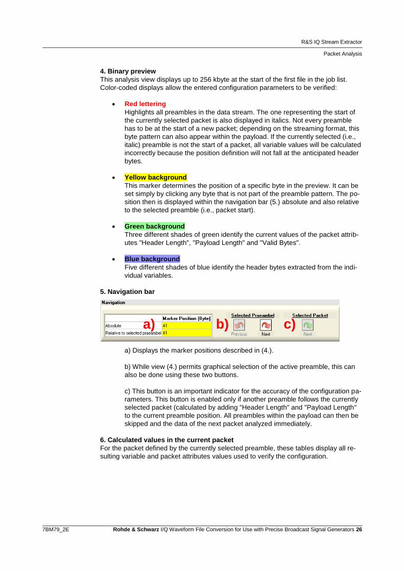
5. Navigation bar
a) Displays the marker positions described in (4.).
b) While view (4.) permits graphical selection of the active preamble, this can
also be done using these two buttons.
c) This button is an important indicator for the accuracy of the configuration pa-
rameters. This button is enabled only if another preamble follows the currently
selected packet (calculated by adding "Header Length" and "Payload Length"
to the current preamble position. All preambles within the payload can then be
skipped and the data of the next packet analyzed immediately.
6. Calculated values in the current packet
For the packet defined by the currently selected preamble, these tables display all re-
sulting variable and packet attributes values used to verify the configuration.
a) b) c)

Application Example
R&S IQ Stream Extractor
7BM79_2E Rohde & Schwarz I/Q Waveform File Conversion for Use with Precise Broadcast Signal Generators 27
4 Application Example The R&S PR100 is a portable receiver that can record FM radio channels as I/Q wave-
form files:
Fig. 11: R&S PR100.
The R&S PR100 file format does not correspond to that of the described R&S SFU,
R&S SFE and R&S SFE100 signal generators, and it is also packet-oriented. This file
format therefore provides an excellent example of an R&S IQ Stream Extractor and
R&S IQ Converter application. The file "R&S_(R)_PR100_StreamExample_V100.riq"
used in this example can be downloaded free of charge from the download page of this
application note in order to reproduce the steps outlined here. The download includes
several minutes of an FM radio channel in which the receive frequency changes multi-
ple times.
4.1 R&S IQ Stream Extractor
1 Because the I/Q sample values from the R&S PR100 to be converted are available in packet-oriented form, R&S IQ Stream Extractor is launched first for preprocessing:
1a Start R&S IQ Stream Extractor.

Application Example
R&S IQ Stream Extractor
7BM79_2E Rohde & Schwarz I/Q Waveform File Conversion for Use with Precise Broadcast Signal Generators 28
2 Initially, the R&S PR100 streaming format is not known to R&S IQ Stream Extractor. Therefore, a configuration file must be created that describes the correct data processing for the program. For future conversions, the configuration file matching this input format is simply selected.
To simplify creation of the configuration, the "R&S_(R)_PR100_StreamExample_V100.riq" file to be converted is added to the extraction list. The Packet Analysis view then become available based on the first entry in the list:
2a In the integrated File Browser, select
"R&S_(R)_PR100_StreamExample_V100.riq".
2b Double-click the file to add it to the job list.
2c Click the "Packet Analysis" tab in the upper left-
hand corner to switch to the Packet Analysis
view.

Application Example
R&S IQ Stream Extractor
7BM79_2E Rohde & Schwarz I/Q Waveform File Conversion for Use with Precise Broadcast Signal Generators 29
3 Refer to the R&S PR100 manual for the description of the streaming format:
Preamble pattern: 000EB200
"Attribute Length" header information is associated with the total packet length
"Optional Header Length" header information supplies the header length
"IF Samplerate" header information corresponds to the I/Q sample rate
"IF Frequency" header information can serve as the stream ID
=> Each of these available values should now be assigned a variable The format and position of these values are taken from their description in the manual
3a Set the "Preamble" configuration parameter to
"000EB200".
Note how the specified preamble pattern is au-
tomatically highlighted in red in the preview.
3b Configuration of variable A:
Description = "Attribute Length"
Position = "18"
Endianess = "Big"
Format = "16 Bit Unsigned Integer"
The specified variable position and length are
automatically highlighted in light blue in the pre-
view. The table below also displays the descrip-
tion and the current variable value "32832".
3c Configuration of variable B:
Description = "Optional Header Length"
Position = "23"
Endianess = "Big"
Format = "8 Bit Unsigned Integer"
The previews are updated again and display "56"
as the current value.

Application Example
R&S IQ Stream Extractor
7BM79_2E Rohde & Schwarz I/Q Waveform File Conversion for Use with Precise Broadcast Signal Generators 30
3d Configuration of variable C:
Description = "IF Samplerate"
Position = "32"
Endianess = "Little"
Format = "32 Bit Integer"
The previews are updated again and display
"32000" as the current value.
3e Configuration of variable D:
Description = "IF Frequency"
Position = "36"
Endianess = "Little"
Format = "32 Bit Unsigned Integer"
The previews are updated again and display
"98500000" as the current value.

Application Example
R&S IQ Stream Extractor
7BM79_2E Rohde & Schwarz I/Q Waveform File Conversion for Use with Precise Broadcast Signal Generators 31
4 The values calculated on the basis of the four variables do not directly match the packet attrib-utes required by the program. Therefore, mathematical expressions must be derived:
"Header Length" can be calculated from the information provided in variable B ("Op-tional Header Length"). This is because the format description in the manual indicates that only a constant offset of 32 needs to be added. The calculation formula is therefore "B+32".
"Stream ID" is linked directly to variable D ("IF Frequency") because a change in the R&S PR100 receive frequency implies a new I/Q data stream. To improve readability, the value is converted from Hz to MHz ("D/1000000").
"Samplerate [MHz]" is calculated on the basis of variable C ("IF Samplerate"). Because variable C is also in Hz, it is similarly divided by 1000000 ("C/1000000").
"Payload Length" is governed primarily by variable A ("Attribute Length"): Adding the offset of 20 provides the total packet length. From this, only the header length (B+32) still needs to be subtracted: "A+20-(B+32)".
For the R&S PR100, "Valid bytes" always corresponds to "Payload Length": "A+20-(B+32)".
4a For "Header Length", enter the formula "B+32".
The previews are updated again and display "88"
as the current value.
4b For "Header Stream ID", enter the formula
"D/1000000".
This returns the current value "98".

Application Example
R&S IQ Stream Extractor
7BM79_2E Rohde & Schwarz I/Q Waveform File Conversion for Use with Precise Broadcast Signal Generators 32
4c For "Header Samplerate", enter the formula
"C/1000000".
This returns the current value "0.032".
4d For "Payload Length", enter the formula "A+20-
(B+32)".
The previews are updated again and display
"32764" as the current value.
4e For "Valid bytes", enter the formula
"A+20-(B+32)".
The previews are updated again and display
"32764" as the current value.

Application Example
R&S IQ Stream Extractor
7BM79_2E Rohde & Schwarz I/Q Waveform File Conversion for Use with Precise Broadcast Signal Generators 33
5 After all configuration parameters have been entered, check to ensure that R&S IQ Stream Ex-tractor is correctly interpreting the input file. The verified configuration is then named and saved.
5a If the packet structure is interpreted successfully,
the "Selected Packet – Next" button in the navi-
gation bar is enabled. Click the button, then
check the lower table view (Current Packet Val-
ues) to verify that the values of the variables and
their derived attributes have been correctly de-
termined for the subsequent packets.
5b Enter the configuration name R&SPR100" in the
text field at the upper right-hand corner, then
click the button with the diskette icon to save the
configuration.
6 Because the R&S PR100 input file "R&S_(R)_PR100_StreamExample_V100.riq" is present in the job list and a matching configuration is enabled, the actual extraction can now take place:
6a Click the "Start extraction jobs" button at the
lower right.

Application Example
R&S IQ Converter
7BM79_2E Rohde & Schwarz I/Q Waveform File Conversion for Use with Precise Broadcast Signal Generators 34
6b After the extraction is completed, the status line
for this entry in the job list indicates that six
streams have been successfully extracted. The
File Browser contains a new folder with the
name of the input file
("\R&S_(R)_PR100_StreamExample_V100.riq\"),
which in turn contains the six files, each named
after the stream ID:
100.iqs
102.iqs
458.iqs
91.iqs
94.iqs
98.iqs
4.2 R&S IQ Converter
1 Because R&S IQ Stream Extractor has split the individually recorded FM radio channels from the R&S PR100 into separate I/Q waveform files without a packet structure, R&S IQ Converter can be used to perform the actual conversion into the proprietary format for the R&S SFU, R&S SFE and R&S SFE100 signal generators.
1a Start R&S IQ Converter.
2 Initially, the input format is not known to R&S IQ Converter. Therefore, a configuration file must be created that describes the correct data processing for the program. For future con-versions, the configuration file matching this input format is simply selected.
To simplify creation of the configuration, the files to be converted ("100.iqs" to "98.iqs") are added to the extraction list. The analysis views then become available based on the first entry in the list:
2a In the integrated File Browser, select all files in
the
"\R&S_(R)_PR100_StreamExample_V100.riq\"
folder.

Application Example
R&S IQ Converter
7BM79_2E Rohde & Schwarz I/Q Waveform File Conversion for Use with Precise Broadcast Signal Generators 35
2b Click the "Add IQ" button to add the selected
files to the job list.
2c Click the "Metadata Analysis" tab in the upper
left-hand corner to switch to the Metadata
Analysis view.
3 The first configuration parameters to be defined tell the software how to handle the metadata; i.e., the header and trailer of the input files. In this case, this structure was generated by R&S IQ Stream Extractor. The header and trailer preview in R&S IQ Converter make the necessary settings easily recognizable:
"Header Length": This text header has a variable length and ends at "#"
"Trailer Length": No trailer is present
"Comment": The stream ID in the header can be used as the comment
"Samplerate": Is listed in the header text and can be extracted
3a Configuration of "Header Length":
Source = "Header – End Pattern"
Specifies that the mandatory value "Header
Length" is defined based on the "End Pattern"
information in the "Header" source.
End Pattern = "#"
The resulting header length is then automati-
cally highlighted in green in the preview. In the
table at the bottom of the screen, the current
value "131" is also displayed.

Application Example
R&S IQ Converter
7BM79_2E Rohde & Schwarz I/Q Waveform File Conversion for Use with Precise Broadcast Signal Generators 36
3b Configuration of "Trailer Length":
Source = "User"
In contrast to the preceding header length con-
figuration, no trailer is present here and infor-
mation regarding its length can be extracted.
Therefore, this value must be defined by the
user.
Value = "0"
This is also seen in the previews.
3c Configuration of "Comment":
Source = " Header – Variable Position"
Prefix = "ID: "
Suffix = "}"
Analogous to the dynamic calculation of the
header length, this configuration extracts the
header text "Stream ID" as the comment.
In both previews, the correct extraction of the
comment can then be verified.
3d Configuration of "Samplerate":
Source = " Header – Variable Position"
Type = "Text Floating Point"
Prefix = "[MHz]: "
Unit = "MHz"
Analogous to extraction of the comment.

Application Example
R&S IQ Converter
7BM79_2E Rohde & Schwarz I/Q Waveform File Conversion for Use with Precise Broadcast Signal Generators 37
3f Click the "IQ Analysis" tab in the upper left-
hand corner to change to the IQ Analysis view.
4 The I/Q parameters are easily configured because the I/Q format of the R&S PR100 exactly matches the default settings in R&S IQ Converter. By increasing the number of sample values displayed in the preview, the level of detail for the displayed signal spectrum is increased.
4a Set "IQ Samples for Preview" to "1024".
In the IQ Preview, the correct interpretation of
the I/Q sample values is seen in both the time
domain and the frequency domain.
4b Click the "Signal Processing" tab in the upper
left-hand corner to change to the Signal Pro-
cessing view.

Application Example
R&S IQ Converter
7BM79_2E Rohde & Schwarz I/Q Waveform File Conversion for Use with Precise Broadcast Signal Generators 38
5 The signal processing functions are optional for the conversion process. However, because the frequency display in the IQ Preview already shows an unnecessarily memory-intensive oversampling, it makes sense to reduce the sample rate by using an appropriately dimen-sioned lowpass filter. This completes the configuration, which can now be saved:
5a Configuration of Lowpass Filtering:
Type = "Blackman Window"
Cutoff [f/fs] = "0.07”
Number of Taps = "128"
Output Samplerate =
"Input Samplerate x 2/10)"
These values can also be determined experi-
mentally thanks to the detailed preview.
5b Enter the configuration name "R&SPR100 -
FM filtered" in the text field at the upper right-
hand corner, then click the button with the
diskette icon to save the configuration.
6 Because the files to be converted are present in the job list and a matching configuration is enabled, the actual processing can now start:
6a Click the "Start conversion jobs" button at the
lower right.

Application Example
R&S IQ Converter
7BM79_2E Rohde & Schwarz I/Q Waveform File Conversion for Use with Precise Broadcast Signal Generators 39
6b After all conversions have been completed, the
results are displayed in the File Browser:
100.iqs.wv
102.iqs.wv
458.iqs.wv
91.iqs.wv
94.iqs.wv
98.iqs.wv
The selected filtering and associated sample
rate reduced the space requirements by 80 %.
The converted I/Q waveform files can now be replayed using the ARB function offered
by the R&S SFU, R&S SFE and R&S SFE100 signal generators:
Fig. 12: Spectrum of "100.iqs.wv" waveform after reconstruction by the R&S SFU.
Frequently Asked Questions
General
7BM79_2E Rohde & Schwarz I/Q Waveform File Conversion for Use with Precise Broadcast Signal Generators 40
5 Frequently Asked Questions
5.1 General
Why are no floppy/network drives displayed in the File Browser?
For reasons of performance, the I/Q waveform files should be stored locally.
Why is my USB stick not displayed in the File Browser?
USB sticks inserted while the program is running are not recognized. Exit the program
and launch it again.
How can I remove a conversion job from the list?
Click the checkbox to the right of the job number:
Where can I get software updates and example configurations?
Refer to chapter 7 for further information.
I created several configurations. How can I use these on other PCs?
Every configuration is saved in the installation directory in a separate file under its con-
figuration name. Simply copy these files to the installation directory on the other PC.
When the program is launched, all configurations stored in this location are recognized.
A configuration entry is marked as incorrect. Why isn't there a context-sensitive
tooltip providing an explanation?
The context-sensitive tooltip appears only when the field isn't being edited. Press the
"Enter" key to exit the input mode for that field.
5.2 R&S IQ Converter
5.2.1 Analysis
Why can't I find an I/Q waveform in the file, even though I tried all I/Q format op-
tions?
If more than one byte is used for each sample value in the I/Q waveform, then the se-
lected header length as well as the selected I/Q format will make a difference. Increase
the header length in 1 byte increments until the start of the I/Q data range matches the
start of a sample value.

Frequently Asked Questions
R&S IQ Converter
7BM79_2E Rohde & Schwarz I/Q Waveform File Conversion for Use with Precise Broadcast Signal Generators 41
I have a file with I/Q sample values in text format. Why can't I use some of the
program functions?
Unfortunately, these types of files cannot be navigated efficiently and cleanly at the
same time. It is therefore recommended that you first convert the file to the binary
Rohde & Schwarz format with less functionality, and then reopen the results with all
remaining functions available, including the I/Q interval selection function.
How do I activate the "Interval Stop" cursor?
This is available only for binary I/Q formats. Set the IQ:Interval Selection:Last Sample
to "User" and then select the "Interval Stop" cursor above the IQ Preview graph.
Please note that the cursor becomes transparent when passed over invalid positions.
Why is the displayed stopband attenuation lower when I increase the number of
taps for the lowpass filter?
A higher number of taps leads to an increased stopband attenuation. If this is not dis-
played correctly, the number of I/Q sample values used for the preview will be lower
than the number of taps. To correct the display, select at least 1024 sample values in
the IQ Analysis view:
Fig. 13: Effect of the number of I/Q samples used for preview on the filter display.
5.2.2 Conversion
Why doesn't the conversion work?
This can have a number of different causes:
The current configuration doesn't match the input file. To obtain details, go to
the job list and delete all entries above this job so that the problematic file is
first in the list to be analyzed. View the tooltips for the invalid configuration pa-
rameters to resolve the problem.
An output file with the same name already exists, and overwrite protection is
active. Deactivate write protection.
The scale factor was defined manually and is too small or too large. Use the
recommended scale factor, or activate the IQ:Scale Factor:Auto Optimization
function.

Frequently Asked Questions
R&S IQ Converter
7BM79_2E Rohde & Schwarz I/Q Waveform File Conversion for Use with Precise Broadcast Signal Generators 42
Why do extra glitches appear in the spectrum when the I/Q waveform is played?
If the waveform generator reaches the end of the waveform during playback, the play-
back will automatically continue at the start of the I/Q waveform. If the sample values at
the start of the I/Q waveform don't follow the signal trace described by the end of the
I/Q waveform, the discontinuity will cause glitches in the spectrum. Optimize using the
Seamless Loop preview in the IQ View.
Why does the conversion take so long?
Two conversion settings will affect the conversion speed significantly:
1. If IQ:Scale Factor:Auto Optimization is enabled, the conversion will take twice
as long because the optimum scale factor is additionally being calculated on
the basis of all sample values. If the value range for the I/Q waveform is al-
ready known, the optimum scale factor can be set manually, thus cutting the
conversion time in half.
2. If a lowpass filter was enabled for channel selection, the conversion time will
increase in direct proportion to the number of selected filter taps. This means
that a filtering with 100 taps will take approximately one-tenth the time of 1000
taps – even though it will be at the cost of the filter quality.
Why were fewer I/Q sample values written than were selected for conversion?
If a lowpass filter was enabled in combination with the resampling function, the number
of I/Q sample values will be reduced by the resampling factor.
Can the conversion results also be played back on other R&S signal generators?
This is possible with the following instruments, although there is also dedicated soft-
ware available [2]:
R&SSMU200A
R&SSMJ100A
R&SSMATE200A
R&SAFQ100A
R&SAFQ100B
R&SSMBV100A
However in doing so, the following limitations apply:
For some instruments, their ARB’s full digital bandwidth of up to 600 MHz can-
not be used, due to the R&S IQ Converter’s sample rate limitation to 100 MHz.

References
R&S IQ Converter
7BM79_2E Rohde & Schwarz I/Q Waveform File Conversion for Use with Precise Broadcast Signal Generators 43
6 References [1] "Generating Interference Signals Using the R&S SFU-K37 Option"
Application Note 7BM50_1E, Rohde & Schwarz
[2] "Importing Data in ARB, Custom Digital Modulation and RF List Mode"
Application Note 1GP62_2E, Rohde & Schwarz
7 Additional Information Our application notes are regularly revised and updated. Check for any changes at
http://www.rohde-schwarz.com Downloads Application Notes 7BM79.
Here you will also find software updates and example configuration files.
Please send any comments and suggestions about this application note
to

Ordering Information
R&S IQ Converter
7BM79_2E Rohde & Schwarz I/Q Waveform File Conversion for Use with Precise Broadcast Signal Generators 44
8 Ordering Information
Designation Type Order No.
R&S BTC
Broadcast Test Center R&S BTC 2114.3000.02
Arbitrary Waveform Generator R&S BTC-K35 2114.3700.02
R&S CLG
Cable Load Generator R&S CLG 2116.9170.02
R&S SLG
Satellite Load Generator R&S SLG 2116.9193.02
R&S SFU
Broadcast Test System R&S SFU 2110.2500.02
ARB Generator R&S SFU-K35 2110.7601.02
Memory Extension 1 R&S SFU-B3 2110.7447.02
R&S SFE
Broadcast Tester R&S SFE 2112.4300.02
ARB Waveform Generator R&S SFE-K35 2113.4932.02
Memory Expansion R&S SFE-B3 2112.4500.02
R&S SFE100
Test Transmitter, Model .02 or Model .03 R&S SFE100 2112.4100.XX
ARB Waveform Generator R&S SFE100-K35 2113.4926.02
Memory Extension R&S SFE100-B3 2112.4400.02

About Rohde & Schwarz
Rohde & Schwarz is an independent group
of companies specializing in electronics. It is
a leading supplier of solutions in the fields of
test and measurement, broadcasting, radio-
monitoring and radiolocation, as well as
secure communications. Established more
than 75 years ago, Rohde & Schwarz has a
global presence and a dedicated service
network in over 70 countries. Company
headquarters are in Munich, Germany.
Environmental commitment
● Energy-efficient products
● Continuous improvement in environ-
mental sustainability
● ISO 14001-certified environmental
management system
Regional contact
Europe, Africa, Middle East
+49 89 4129 12345
[email protected] North America
1-888-TEST-RSA (1-888-837-8772)
[email protected] Latin America
+1-410-910-7988
[email protected] Asia/Pacific
+65 65 13 04 88
This application note and the supplied
programs may only be used subject to the
conditions of use set forth in the download
area of the Rohde & Schwarz website.
R&S® is a registered trademark of Rohde & Schwarz GmbH & Co. KG; Trade names are trademarks of the owners.
Rohde & Schwarz GmbH & Co. KG
Mühldorfstraße 15 | D - 81671 München
Phone + 49 89 4129 - 0 | Fax + 49 89 4129 – 13777
www.rohde-schwarz.com