ipass open device framework (odf) training...
TRANSCRIPT

iPass Open Device Framework (ODF) Training Workbook
V E R S I O N 2 . 2 , A P R I L 2 0 1 3
Corporate Headquarters iPass Inc. 3800 Bridge Parkway Redwood Shores, CA 94065 USA www.ipass.com +1 650-232-4100 +1 650-232-0227 fx

3
TABLE OF CONTENTS
iPass Open Device Framework (ODF) Train ing W orkbook
2013 iPass Inc. 3
Introduction to Open Device Framework (ODF) 6
ODF Implementation .............................................................................................................................. 7
Limitations .............................................................................................................................................. 8
Prerequisites ........................................................................................................................................... 8
Supported Operating Systems ............................................................................................................. 9
Knowledge Review Questions .............................................................................................................. 9
Analyzing the Mobile Broadband Device 10
Preparation ........................................................................................................................................... 10
Device Information ............................................................................................................................... 10
Port Details in the Device Manager .................................................................................................... 11
Audit the Device with SerialTerm ....................................................................................................... 19
Completing Device Details .................................................................................................................. 21
Knowledge Review Questions ............................................................................................................ 21
Using the ODF Library 22
Navigating the Portal ........................................................................................................................... 22
Searching the ODF Library .................................................................................................................. 22
Downloading a Sample ODF Template .............................................................................................. 23
Downloading a Blank ODF Template ................................................................................................. 23
Knowledge Review Questions ............................................................................................................ 24
Editing the ODF 25
Assigning a Device ID .......................................................................................................................... 25
AdminWWDevices ................................................................................................................................ 25
MBLite: Device ID ................................................................................................................................. 25
MBLite: Ports ........................................................................................................................................ 25
MBLite: DeviceSettings ....................................................................................................................... 28
MBLite: DeviceFunctionality (Optional) ............................................................................................. 30
Save the Files ....................................................................................................................................... 30
XML Editing ........................................................................................................................................... 31
Choosing the Right Template ............................................................................................................. 31
Edit the XML Templates ....................................................................................................................... 31

4
TABLE OF CONTENTS
iPass Open Device Framework (ODF) Train ing W orkbook
2013 iPass Inc. 4
Verify the XML ...................................................................................................................................... 31
Knowledge Review Questions ............................................................................................................ 31
Testing the ODF 32
Test ........................................................................................................................................................ 32
Additional Tests ................................................................................................................................... 32
Knowledge Review Questions ............................................................................................................ 33
Uploading and Deploying the ODF 34
Upload the File to the Open Mobile Portal ......................................................................................... 34
Deploy the ODF .................................................................................................................................... 35
Knowledge Review Questions ............................................................................................................ 35
Troubleshooting 36
Support .................................................................................................................................................. 36
Tips ........................................................................................................................................................ 36
MBLite.log ............................................................................................................................................. 36
Error Messages .................................................................................................................................... 37
Detection Failure .................................................................................................................................. 38
Verification Failure ............................................................................................................................... 39
Functionality Failure ............................................................................................................................ 39
Knowledge Review Questions ............................................................................................................ 40
Appendix A: Port Details 41
Appendix B: Audit Information 42
Device Information ............................................................................................................................... 42
Manufacturer and Model ...................................................................................................................... 42
Device Details ....................................................................................................................................... 42
Audit AT Commands ............................................................................................................................ 43
Appendix C: XML Reference 45
XML Format ........................................................................................................................................... 45
AdminWWDevices ................................................................................................................................ 45
MBLite: Device ID ................................................................................................................................. 45
MBLite: Ports ........................................................................................................................................ 45

5
TABLE OF CONTENTS
iPass Open Device Framework (ODF) Train ing W orkbook
2013 iPass Inc. 5
MBLite: DeviceInfo ............................................................................................................................... 46
MBLite: DeviceSettings ....................................................................................................................... 47
MBLite: DeviceFunctionality (Optional) ............................................................................................. 47
AT Commands (Optional) .................................................................................................................... 47
Appendix D: AT Commands 48
Functionalities Used in ODF Integration ........................................................................................... 48
AT Commands for the SIM Card ......................................................................................................... 58
CDMA ..................................................................................................................................................... 69
Appendix E: SMS Configuration 75
Before Configuring SMS ...................................................................................................................... 75
Configuration Procedure ..................................................................................................................... 75
6
Introduction to Open Device Framework (ODF)
iPass Open Device Framework (ODF) Train ing W orkbook
2013 iPass Inc. 6
Introduction to Open Device Framework (ODF)
Integrating new Mobile Broadband devices into Open Mobile has become increasingly challenging, especially as more
and more devices are introduced to the market. Using a traditional engineering development approach incurs a three to six-
month cycle. This delay can have a significant impact on the acceptability of Open Mobile to many customers, especially
since most Mobile Broadband devices have about a six-month shelf life. Though most vendors will continue to support their
devices for up to three years after End of Life is announced, the customer tends not to consider End of Life devices as
viable, especially if contractual terms may mean that the device is no longer supported before the end of the contract.
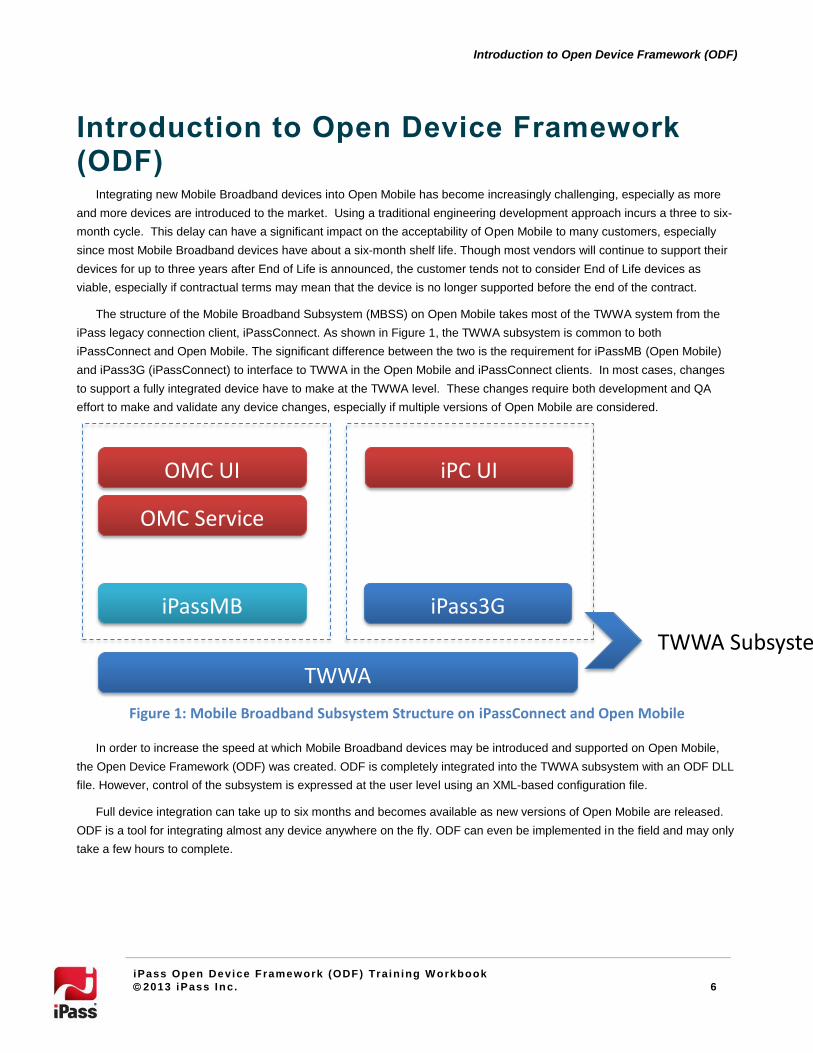
The structure of the Mobile Broadband Subsystem (MBSS) on Open Mobile takes most of the TWWA system from the
iPass legacy connection client, iPassConnect. As shown in Figure 1, the TWWA subsystem is common to both
iPassConnect and Open Mobile. The significant difference between the two is the requirement for iPassMB (Open Mobile)
and iPass3G (iPassConnect) to interface to TWWA in the Open Mobile and iPassConnect clients. In most cases, changes
to support a fully integrated device have to make at the TWWA level. These changes require both development and QA
effort to make and validate any device changes, especially if multiple versions of Open Mobile are considered.
Figure 1: Mobile Broadband Subsystem Structure on iPassConnect and Open Mobile
In order to increase the speed at which Mobile Broadband devices may be introduced and supported on Open Mobile,
the Open Device Framework (ODF) was created. ODF is completely integrated into the TWWA subsystem with an ODF DLL
file. However, control of the subsystem is expressed at the user level using an XML-based configuration file.
Full device integration can take up to six months and becomes available as new versions of Open Mobile are released.
ODF is a tool for integrating almost any device anywhere on the fly. ODF can even be implemented in the field and may only
take a few hours to complete.
OMC UI iPC UI
OMC Service
iPassMB
iPass3G
TWWA
TWWA Subsystem

7
Introduction to Open Device Framework (ODF)
iPass Open Device Framework (ODF) Train ing W orkbook
2013 iPass Inc. 7
ODF Implementation
Open Mobile can support the two main mobile broadband network types: GSM/GPS and CDMA. (These terms are
rapidly becoming obsolete and they are more normally referred to as 2G or 3G networks.) However, for the purposes of this
training document the terms GSM/GPRS and CDMA will continue in use.
Table 1 shows there are a variety of bearer types on the market. All of these technologies can be quite easily supported
with the Open Device Framework (ODF).
Bearer Technology Peak Rate Available (Kbps) Potential Rates (Kbps) Year
GSM CSD (2G) 9.6 9.6 1991
HSCSD 115 115 ~1999
CDMA2000 1xRTT 153 153 1999
GPRS (2.5G) 115 115 ~2000
UMTS/3G 384
384 2002
1xEV-DO Rev.A 3,072 3,100 2007
HSDPA/HSUPA (3.5G) 2,000-5,760 1,200-14,400 2009
HSPA+ (~3.99G) 21,600 17,600-42,000 2009
WiMAX (~3.99G) 2,700 10,000 2009
3xEV-DO Rev.B 4,900-14,900 14,900 2010
DC-HSPA+ 23,400-42,200 23,400-84,000 2010
LTE (~3.99G) 12,000 100,000 2010
LTE-Advanced (4G) X 100MBps-1GBps >2012
Table 1: Bearer types currently deployed
By following a few simple steps as outlined in the following chapters, it is possible to create an ODF script that will allow
you to run virtually any MBB device on Open Mobile. Figure 2 provides an overview of the process you can follow to
determine if you need to request a full integration or can provide an ODF integration.

8
Introduction to Open Device Framework (ODF)
iPass Open Device Framework (ODF) Train ing W orkbook
2013 iPass Inc. 8
New Card
Collect Details
Check Portal
Full Integration/
4G/ Operator
Search for ODF Template
Full Integration
Request Full Integration
Audit Device
Added to OM/MBSS Release
Download ODF Template from
OM Portal
Request iPass ODF
Delivered as part of OM/
MBSS
Edit ODF Test ODFSave ODF to My Devices
Include in Profile
iPass generates ODF
Done
Manufacturer, Brand,
Technology, OS, Network, etc.
Figure 2: Simplified workflow for device integrations
Limitations
ODF is a great tool for quickly integrating devices, but there are limitations.
Not Fully Supported by iPass: One implication of the speed of ODF integration is that ODF integrated
devices do not pass through iPass QA testing. Therefore, they cannot be fully supported by iPass.
No 4G/#G Switching: 4G devices have been successfully integrated using ODF. However, they are unable to
switch from 4G to 3G, and therefore, only function where there is 4G coverage.
Prerequisites
Before beginning, ensure that you have the following:
An XML editor (Notepad ++, XML Notepad, or others).
Open Mobile 1.2 for Windows or later.
SerialTerm (or another terminal emulator such as HyperTerminal).
Access to the Open Mobile Portal.
A Mobile Broadband device that supports AT commands (in rare cases AT command documentation may be
necessary). In some cases, it may not be possible to use ODF integration for a Mobile Broadband device, and
these devices have to go through Full Integration.

9
Introduction to Open Device Framework (ODF)
iPass Open Device Framework (ODF) Train ing W orkbook
2013 iPass Inc. 9
Supported Operating Systems
The Mobile Broadband ODF Integration has been tested on the following operating systems:
Windows XP Professional with Service Pack 3 (32-bit)
Windows Vista Enterprise with Service Pack 2 (32-bit and 64-bit)
Windows 7 Enterprise (32-bit and 64-bit)
Knowledge Review Questions
1. What does ODF stand for?
2. Where does TWWA sit within Open Mobile?
3. What language is used to write ODF scripts?
4. Which of the following data bearer devices cannot be integrated with ODF?
WiMAX
HSPA+
CDMA EVDO
MiFi

10
Analyzing the Mobile Broadband Device
iPass Open Device Framework (ODF) Train ing W orkbook
2013 iPass Inc. 10
Analyzing the Mobile Broadband Device
Preparation
Take the following steps to prepare the device for ODF integration.
1. Make sure that you have an XML editor (Notepad ++, XML Notepad, or others), SerialTerm (or other terminal
emulator), and the custom XML templates from iPass. The descriptions in this document are based on these
tools, as they are known to work. Other tools may cause problems especially when generating XML files.
2. Install the Mobile Broadband device, its drivers, and its native connection client. Verify that it can connect to a
network with the native client.
3. Verify that the device is not already fully integrated by seeing if it is recognized by Open Mobile:
For Open Mobile client versions 1.3 or earlier, launch Open Mobile and see if the device is listed when you
select Tools | Manage Devices | Mobile Broadband.
For Open Mobile client version 1.4 or later, launch Open Mobile and see if the device is listed when you select
Tools | Mobile Broadband.
4. Before proceeding, disable all connection clients without turning off the radio on the Mobile Broadband device
or disabling the device in any other way.
Disable all connection clients including iPassConnect (by exiting it) and Open Mobile (make sure that all
services are discontinued).
You can discontinue Open Mobile services by launching the Command Prompt and entering “net stop
iMobilityservice”, and after iMobilityservice stops, entering “net stop iPlatformservice”.
Later, you can restart the services by entering “net start iMobilityservice” and after
iMobilityservice restarts, entering “net start iPlatformservice”.
Make sure that the device does not go into Flight Mode when the native connection client is disabled (this can
usually be fixed by changing the configuration option in the native client).
Make sure that the device is not turned off when the native connection client is disabled.
Device Information
As part of the preparation, gather as much information about the device as you can from the box and label. Include this
information in the first table in Appendix B.
3G Technology: Is the device GPRS or CDMA? Examples of GPRS technology include: UMTS, EDGE, GSM,
HSPA, and WCDMA. Examples of CDMA technology include: 1xRTT, EV-DO, RevA.
4G Technology is not yet supported for ODF integration.
Brand Name: The device’s manufacturer (for example, Sierra Wireless, ZTE, Huawei, or Novatel). The device
may be rebranded by the operator (which did not manufacture the device), but the manufacturer is the
important information.
Model: The model name for the device.
Network (intended for use): The network, if any, that the devices was intended to be used with (examples
include AT&T, Verizon, Telstra, O2, Vodafone, T-Mobile, and Sprint).

11
Analyzing the Mobile Broadband Device
iPass Open Device Framework (ODF) Train ing W orkbook
2013 iPass Inc. 11
Any other information: Any other information included on the box or device label that would help identify the device.
Port Details in the Device Manager
Use the Device Manager to gather all necessary information about the device’s ports and fill in the tables in Appendix A.
Identify the Ports
To identify all ports associated with the device:
1. Launch the Device Manager
2. Expand Modems, Network Adapters, and Ports.
3. Any ports associated with the device should be clearly indicated. If you are not sure which ports are associated
with the device, unplug the device, and note any ports that disappear (after the Device Manager has enough
time to refresh).
Modem: There has to be a modem port to integrate the device. Go to the Modem Port section below to fill out
the table in Appendix A.
Network Adapter: If there is an NDIS Port, it will be listed here. If found, use the NDIS Port section below to
fill out the table in Appendix A. Not all devices have an NDIS Port.
Ports: If there is an AT Command Port, it will be listed here. Use the Additional Port section below to fill out
the table in Appendix A. If the AT Command Port is not clearly indicated, then include any additional ports in
Appendix A (and use the Primary Port process on page 10 to determine the AT Command Port).
12
Analyzing the Mobile Broadband Device
iPass Open Device Framework (ODF) Train ing W orkbook
2013 iPass Inc. 12
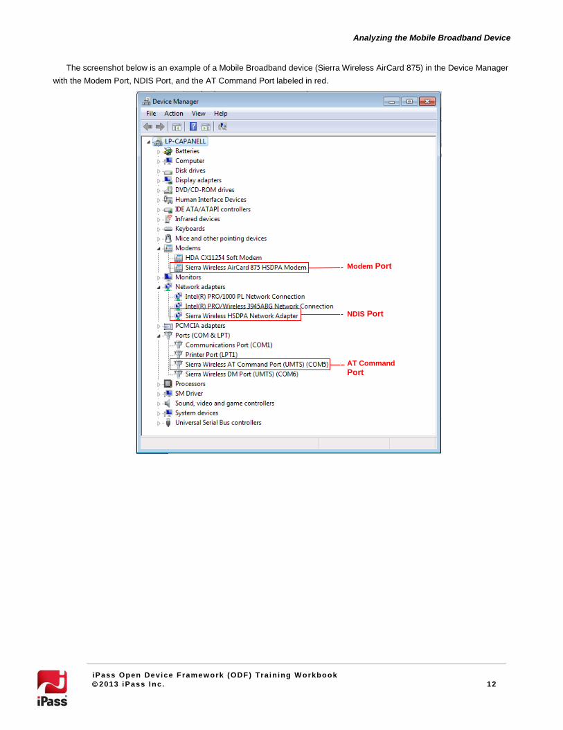
The screenshot below is an example of a Mobile Broadband device (Sierra Wireless AirCard 875) in the Device Manager
with the Modem Port, NDIS Port, and the AT Command Port labeled in red.
Modem Port
NDIS Port
AT Command
Port

13
Analyzing the Mobile Broadband Device
iPass Open Device Framework (ODF) Train ing W orkbook
2013 iPass Inc. 13
Modem Port
Use the following steps to fill out the first table in Appendix A.
1). Open Properties
Launch Device Manger. Right click on the device’s modem port and select Properties.
14
Analyzing the Mobile Broadband Device
iPass Open Device Framework (ODF) Train ing W orkbook
2013 iPass Inc. 14
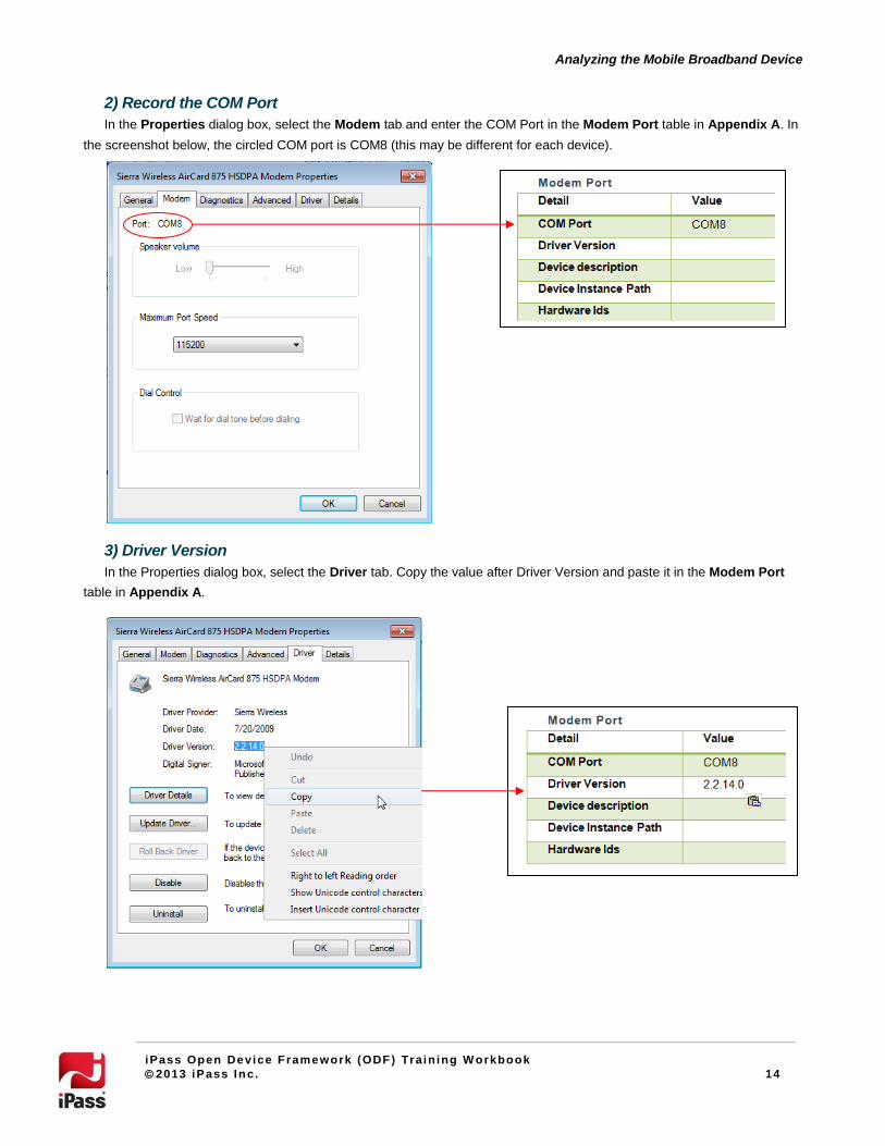
2) Record the COM Port
In the Properties dialog box, select the Modem tab and enter the COM Port in the Modem Port table in Appendix A. In
the screenshot below, the circled COM port is COM8 (this may be different for each device).
3) Driver Version
In the Properties dialog box, select the Driver tab. Copy the value after Driver Version and paste it in the Modem Port
table in Appendix A.
15
Analyzing the Mobile Broadband Device
iPass Open Device Framework (ODF) Train ing W orkbook
2013 iPass Inc. 15
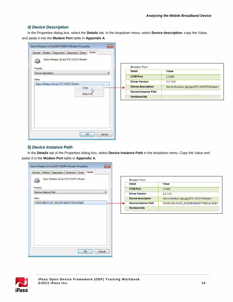
4) Device Description
In the Properties dialog box, select the Details tab. In the dropdown menu, select Device description, copy the Value,
and paste it into the Modem Port table in Appendix A.
5) Device Instance Path
In the Details tab of the Properties dialog box, select Device Instance Path in the dropdown menu. Copy the Value and
paste it in the Modem Port table in Appendix A.

16
Analyzing the Mobile Broadband Device
iPass Open Device Framework (ODF) Train ing W orkbook
2013 iPass Inc. 16
6) Hardware IDs
In the Details tab of the Properties dialog box, select Hardware IDs in the dropdown menu. Copy the Value and paste it
in the Modem Port table in Appendix A.
17
Analyzing the Mobile Broadband Device
iPass Open Device Framework (ODF) Train ing W orkbook
2013 iPass Inc. 17
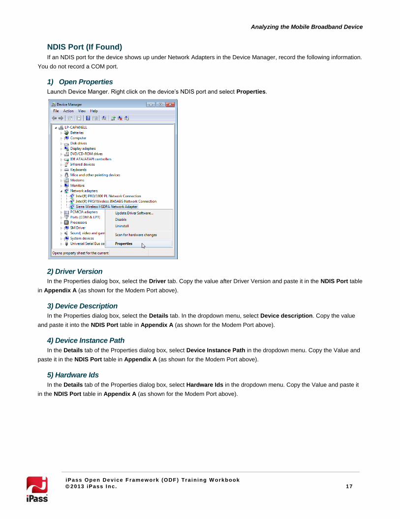
NDIS Port (If Found)
If an NDIS port for the device shows up under Network Adapters in the Device Manager, record the following information.
You do not record a COM port.
1) Open Properties
Launch Device Manger. Right click on the device’s NDIS port and select Properties.
2) Driver Version
In the Properties dialog box, select the Driver tab. Copy the value after Driver Version and paste it in the NDIS Port table
in Appendix A (as shown for the Modem Port above).
3) Device Description
In the Properties dialog box, select the Details tab. In the dropdown menu, select Device description. Copy the value
and paste it into the NDIS Port table in Appendix A (as shown for the Modem Port above).
4) Device Instance Path
In the Details tab of the Properties dialog box, select Device Instance Path in the dropdown menu. Copy the Value and
paste it in the NDIS Port table in Appendix A (as shown for the Modem Port above).
5) Hardware Ids
In the Details tab of the Properties dialog box, select Hardware Ids in the dropdown menu. Copy the Value and paste it
in the NDIS Port table in Appendix A (as shown for the Modem Port above).

18
Analyzing the Mobile Broadband Device
iPass Open Device Framework (ODF) Train ing W orkbook
2013 iPass Inc. 18
Additional (AT Command) Port (If Found)
If an AT Command Port appears under Ports, record the details in the Additional Ports table in Appendix A using the
following process. If several device ports appear and it is not clear which one is the AT Command Port, record the details for
each port and use the process for determining the Primary Port on page 10 to discover the AT Command Port.
1) Open Properties
Launch the Device Manager and expand Ports. Right click on the port and select Properties.

19
Analyzing the Mobile Broadband Device
iPass Open Device Framework (ODF) Train ing W orkbook
2013 iPass Inc. 19
2) COM Port
The COM Port is included at the end of the display name in parenthesis as COMX. Enter this as the COM Port in the
Additional Ports table in Appendix A. In the screenshot below, the circled port is COM5 (this may differ for each device).
3) Device Description
In the Properties dialog box, select the Details tab. In the dropdown menu, select Device description. Copy the value
and paste it into the Additional Ports table in Appendix A (as shown for the Modem Port above).
4) Device Instance Path
In the Details tab of the Properties dialog box, select Device Instance Path in the dropdown menu. Copy the Value and
paste it in the Additional Port table in Appendix A (as shown for the Modem Port above).
4) Hardware IDs
In the Details tab of the Properties dialog box, select Hardware Ids in the dropdown menu. Copy the Value and paste it
in the Additional Port table in Appendix A (as shown for the Modem Port above).
Audit the Device with SerialTerm
You can use any terminal emulator (such as HyperTerminal) that you prefer, but these instructions will deal with the
freely available SerialTerm.
Primary Port
Before auditing the device, determine which COM Port is the Primary Port. In most cases, the AT Command Port (if
found) is the Primary Port, otherwise it is the Modem Port. If there are several additional ports and none of them are clearly
indicated as the AT Command Port, try each port until you receive the correct response. If none of the additional ports are
the AT Command Port, use the Modem Port as your primary port (and ignore the additional ports).
20
Analyzing the Mobile Broadband Device
iPass Open Device Framework (ODF) Train ing W orkbook
2013 iPass Inc. 20
To determine the Primary Port:
1. Open Command Prompt and go to the directory where serialterm.exe is stored.
2. Enter: serialterm.exe [COM Port] 115200.
Start with AT Command Port (if found). For example: serialterm.exe com5 115200.
In rare cases, you may need to adjust the speed (from 115200). If this happens, change the BaudRate Value in
the MBLite: DeviceSettings table in Appendix C.
3. After the device responds, enter: AT+GMI.
If the response is the device manufacturer, then the selected COM Port is the Primary Port, and you are
finished.
If the response is only OK or there is no response, you will need to try another port. Proceed to Step 4.
4. Press escape to exit and try each additional port. If none of the additional ports respond with the device
manufacturer, try the modem port.
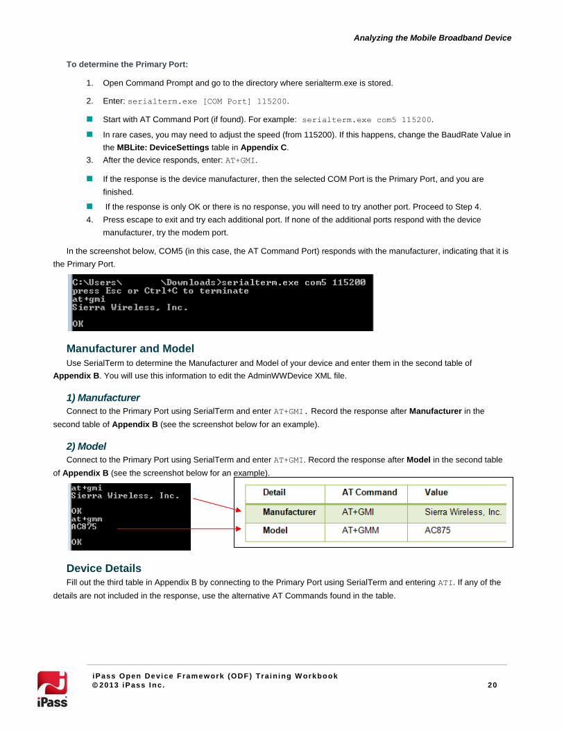
In the screenshot below, COM5 (in this case, the AT Command Port) responds with the manufacturer, indicating that it is
the Primary Port.
Manufacturer and Model
Use SerialTerm to determine the Manufacturer and Model of your device and enter them in the second table of
Appendix B. You will use this information to edit the AdminWWDevice XML file.
1) Manufacturer
Connect to the Primary Port using SerialTerm and enter AT+GMI. Record the response after Manufacturer in the
second table of Appendix B (see the screenshot below for an example).
2) Model
Connect to the Primary Port using SerialTerm and enter AT+GMI. Record the response after Model in the second table
of Appendix B (see the screenshot below for an example).
Device Details
Fill out the third table in Appendix B by connecting to the Primary Port using SerialTerm and entering ATI. If any of the
details are not included in the response, use the alternative AT Commands found in the table.
21
Analyzing the Mobile Broadband Device
iPass Open Device Framework (ODF) Train ing W orkbook
2013 iPass Inc. 21
Audit AT Commands
Follow the instruction in Appendix B to audit the AT Commands. Make sure you only refer to the table(s) of AT
Commands that apply to your device.
AT Commands Not Supported
If any AT Commands are not supported, you will need to find a working replacement in the AT Command documentation
for that family of devices, or elsewhere. Once a replacement AT Command is found and tested, include it in the AT
Command table in Appendix C. If you have to replace an AT Command, use the long.MBLite*.xml when editing the XML.
Replacing non-supported AT Commands is the only purpose of the long schema. You only need to replace the AT
Commands that are not supported (all other commands in the schema can be erased).
Completing Device Details
After you have finished auditing the device with SerialTerm, you should have completed all applicable tables in
Appendixes A and B. Make sure that you have not skipped any steps before moving on. This information is also required if
you approach customer care for support with the integration.
Knowledge Review Questions
1. How do you test if a device is fully integrated already?
2. What are three steps you should take before analyzing a device?
3. What Control Panel applet do you use to analyze the ports?
4. What are the three types of Ports you may find?
5. What are the four details you are looking for in each Port?
6. What is the default Baud Rate of the Primary Port?

22
Using the ODF Library
iPass Open Device Framework (ODF) Train ing W orkbook
2013 iPass Inc. 22
Using the ODF Library This section will describe how to use the ODF Library on the Open Mobile Portal to search for the appropriate ODF
template.
Navigating the Portal
Navigating to the ODF Library
1. Log in to the Open Mobile Portal (openmobile.ipass.com).
2. Select the Configuration tab.
3. Select Device Support.
Searching the ODF Library
You can search the ODF Library for devices that have been fully integrated by iPass (Integrated Support), sample ODF
files (iPass ODF Samples), and devices that your organization has integrated using ODF (My Device Support).
To search the ODF Library:
1. Select the Manufacturer and Model in the dropdown menus, referring to the Manufacturer and Model you
recorded in Appendix B.
You may only find the manufacturer (not the model) or you may not even find the manufacturer (meaning that there are currently no devices by that manufacturer in the ODF library and you will have to use a blank ODF template).
23
Using the ODF Library
iPass Open Device Framework (ODF) Train ing W orkbook
2013 iPass Inc. 23
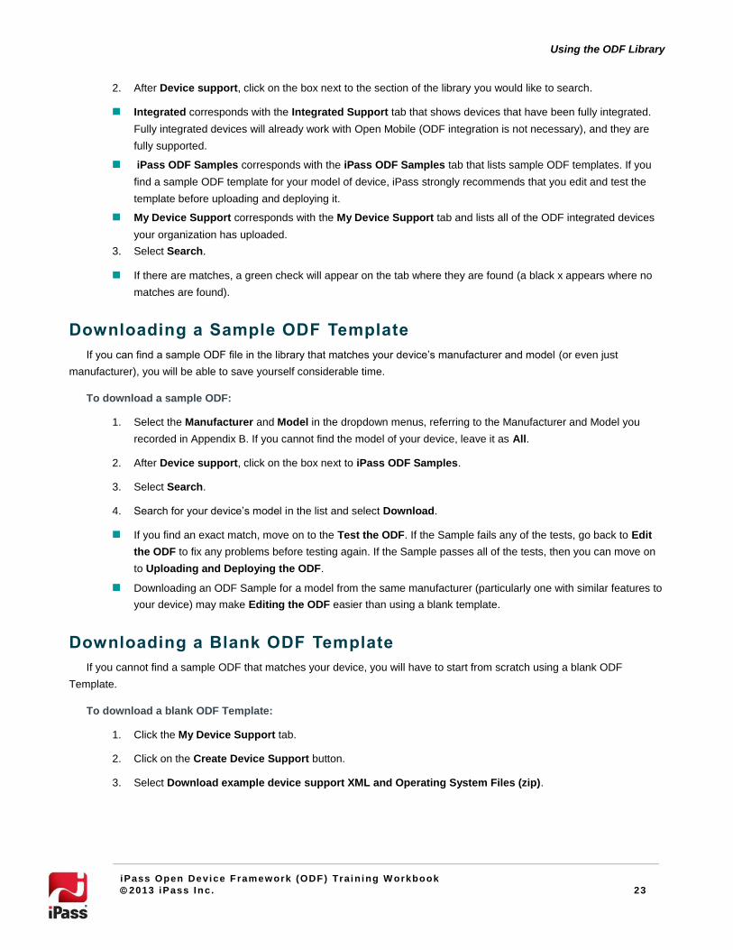
2. After Device support, click on the box next to the section of the library you would like to search.
Integrated corresponds with the Integrated Support tab that shows devices that have been fully integrated.
Fully integrated devices will already work with Open Mobile (ODF integration is not necessary), and they are
fully supported.
iPass ODF Samples corresponds with the iPass ODF Samples tab that lists sample ODF templates. If you
find a sample ODF template for your model of device, iPass strongly recommends that you edit and test the
template before uploading and deploying it.
My Device Support corresponds with the My Device Support tab and lists all of the ODF integrated devices
your organization has uploaded.
3. Select Search.
If there are matches, a green check will appear on the tab where they are found (a black x appears where no
matches are found).
Downloading a Sample ODF Template
If you can find a sample ODF file in the library that matches your device’s manufacturer and model (or even just
manufacturer), you will be able to save yourself considerable time.
To download a sample ODF:
1. Select the Manufacturer and Model in the dropdown menus, referring to the Manufacturer and Model you
recorded in Appendix B. If you cannot find the model of your device, leave it as All.
2. After Device support, click on the box next to iPass ODF Samples.
3. Select Search.
4. Search for your device’s model in the list and select Download.
If you find an exact match, move on to the Test the ODF. If the Sample fails any of the tests, go back to Edit
the ODF to fix any problems before testing again. If the Sample passes all of the tests, then you can move on
to Uploading and Deploying the ODF.
Downloading an ODF Sample for a model from the same manufacturer (particularly one with similar features to
your device) may make Editing the ODF easier than using a blank template.
Downloading a Blank ODF Template
If you cannot find a sample ODF that matches your device, you will have to start from scratch using a blank ODF
Template.
To download a blank ODF Template:
1. Click the My Device Support tab.
2. Click on the Create Device Support button.
3. Select Download example device support XML and Operating System Files (zip).

24
Using the ODF Library
iPass Open Device Framework (ODF) Train ing W orkbook
2013 iPass Inc. 24
Knowledge Review Questions
1. Under what tab in the Open Mobile Portal will you find Device Support?
2. What are the two search terms you can use to find a device in the ODF Library?
3. What does Integrated Support mean?
4. What is your next step if you find an exact match in the ODF Library?
5. Where is the Create Device Support button?
25
Editing the ODF
iPass Open Device Framework (ODF) Train ing W orkbook
2013 iPass Inc. 25
Editing the ODF
Assigning a Device ID
The default Device ID is 3001. Unless you are integrating multiple devices, it is best to keep the default Device ID (this
ensures that the ID will be the same in both XML files and you will be altering the default templates less). The Device ID can
be any numerical value between 3001 and 4000. Make sure you use the same Device ID in both the AdminWWDevices and
the corresponding MBLite XML files. If you decide to change the Device ID, make sure that this is reflected in the first row of
both the AdminWWDevices and RegInfo tables in Appendix C.
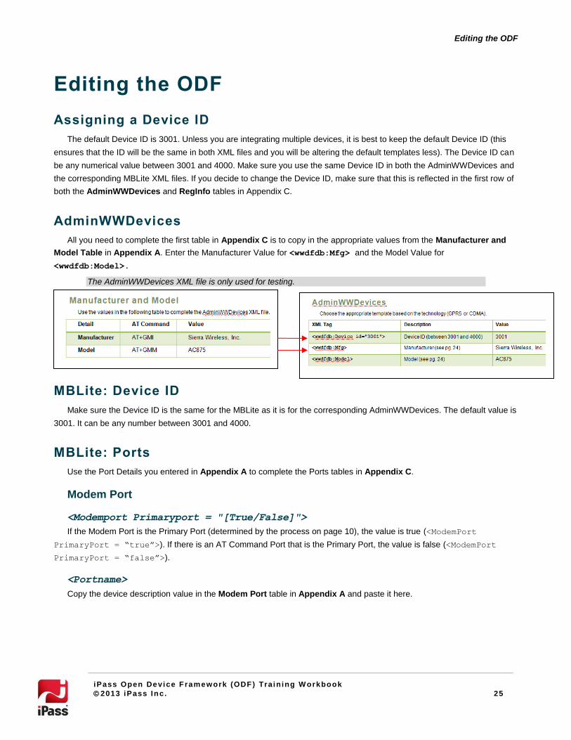
AdminWWDevices
All you need to complete the first table in Appendix C is to copy in the appropriate values from the Manufacturer and
Model Table in Appendix A. Enter the Manufacturer Value for <wwdfdb:Mfg> and the Model Value for
<wwdfdb:Model>.
The AdminWWDevices XML file is only used for testing.
MBLite: Device ID
Make sure the Device ID is the same for the MBLite as it is for the corresponding AdminWWDevices. The default value is
3001. It can be any number between 3001 and 4000.
MBLite: Ports
Use the Port Details you entered in Appendix A to complete the Ports tables in Appendix C.
Modem Port
<Modemport Primaryport = "[True/False]">
If the Modem Port is the Primary Port (determined by the process on page 10), the value is true (<ModemPort
PrimaryPort = “true”>). If there is an AT Command Port that is the Primary Port, the value is false (<ModemPort
PrimaryPort = “false”>).
<Portname>
Copy the device description value in the Modem Port table in Appendix A and paste it here.

26
Editing the ODF
iPass Open Device Framework (ODF) Train ing W orkbook
2013 iPass Inc. 26
<Pnpenum>
In the Modem Port table in Appendix A, the Device Instance Path consists of [PnPEnum]\[PnPID]\[Other Device Data].
For example, if the Device Instance Path is SWMUXBUS\SW_MODEM\8&367376ED&1&6&1 then the PnPENum is
SWMUXBUS (the data before the first backslash). Enter the PnPEnum Value here with proper formatting for XML (&
becomes &).
<Pnpid>
In the Modem Port table in Appendix A, the Device Instance Path consists of [PnPEnum]\[PnPID]\[Other Device Data].
For example, if the Device Instance Path is SWMUXBUS\SW_MODEM\8&367376ED&1&6&1 then the PnPID is
SW_MODEM (the data between the first and second backslashes). Enter the PnPID Value here with proper formatting for
XML (& becomes &).
Sample
The screenshots below show how the device data in Appendix A (first screenshot) is transferred to Appendix C (second
screenshot).
Additional Port
<Additionalport Primaryport = "[True/False]">
If there is an AT Command Port (determined by the process on page 10), the value is true (<ModemPort PrimaryPort
= “true”>). Otherwise, there is no need to list an Additional Port.
<Portname>
Copy the Device description Value in the Additional Port table in Appendix A and paste it here.

27
Editing the ODF
iPass Open Device Framework (ODF) Train ing W orkbook
2013 iPass Inc. 27
<Pnpenum>
In the Additional Port table in Appendix A, the Device Instance Path consists of [PnPEnum]\[PnPID]\[Other Device
Data]. For example, if the Device Instance Path is SWMUXBUS\SW_SERIAL\8&367376ED&1&1&1 then the PnPENum is
SWMUXBUS (the data before the first backslash). Enter the PnPEnum Value here with proper formatting for XML (&
becomes &).
<Pnpid>
In the Additional Port table in Appendix A, the Device Instance Path consists of [PnPEnum]\[PnPID]\[Other Device
Data. For example, if the Device Instance Path is SWMUXBUS\SW_SERIAL\8&367376ED&1&1&1 then the PnPID is
SW_SERIAL (the data between the first and second backslashes). Enter the PnPID Value here with proper formatting for
XML (& becomes &).
Sample
The screenshots below show how the device data in Appendix A (first screenshot) is transferred to Appendix C (second
screenshot).
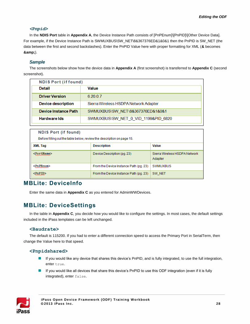
NDIS Port
<Portname>
Copy the Device description Value in the NDIS Port table in Appendix A and paste it here.
<Pnpenum>
In the NDIS Port table in Appendix A, the Device Instance Path consists of [PnPEnum]\[PnPID]\[Other Device Data].
For example, if the Device Instance Path is SWMUXBUS\SW_NET\8&367376ED&1&0&1 then the PnPENum is
SWMUXBUS (the data before the first backslash). Enter the PnPEnum Value here with proper formatting for XML (&
becomes &).
28
Editing the ODF
iPass Open Device Framework (ODF) Train ing W orkbook
2013 iPass Inc. 28
<Pnpid>
In the NDIS Port table in Appendix A, the Device Instance Path consists of [PnPEnum]\[PnPID]\[Other Device Data].
For example, if the Device Instance Path is SWMUXBUS\SW_NET\8&367376ED&1&0&1 then the PnPID is SW_NET (the
data between the first and second backslashes). Enter the PnPID Value here with proper formatting for XML (& becomes
&).
Sample
The screenshots below show how the device data in Appendix A (first screenshot) is transferred to Appendix C (second
screenshot).
MBLite: DeviceInfo
Enter the same data in Appendix C as you entered for AdminWWDevices.
MBLite: DeviceSettings
In the table in Appendix C, you decide how you would like to configure the settings. In most cases, the default settings
included in the iPass templates can be left unchanged.
<Baudrate>
The default is 115200. If you had to enter a different connection speed to access the Primary Port in SerialTerm, then
change the Value here to that speed.
<Pnpidshared>
If you would like any device that shares this device’s PnPID, and is fully integrated, to use the full integration,
enter true.
If you would like all devices that share this device’s PnPID to use this ODF integration (even if it is fully
integrated), enter false.

29
Editing the ODF
iPass Open Device Framework (ODF) Train ing W orkbook
2013 iPass Inc. 29
<Ratmodeenabled>
If the device is part of one of the five families that support RAT Mode (Option, Novatel, Huawei, Sierra
Wireless, or Ericsson), then enter true.
Otherwise, enter false.
As long as you use the correct template, this should already be the case.
<Radioenabled>
If the device is embedded, enter true.
Otherwise, enter false.
<SMSSend>
If the device supports sending SMS messages, enter true.
Otherwise, enter false.
<SMSReceive>
If the device supports receiving SMS messages, enter true.
Otherwise, enter false.
In any case, both <SMSSend> and <SMSReceive> tags must be present.
A Note On <Deviceflags>
There are four manufacturers that require <DeviceFlags>: Novatel, Huawei, Ericsson, and Vtion. This node will already
be filled out if you are using the correct template for that manufacturer. There is also a Device Flag for Plug & Play that only
works on iPassConnect (and is therefore not relevant). The Device Flags for these four manufacturers are listed below
strictly for illustrative purposes.
Manufacturer <DeviceFlags>
Novatel <DeviceFlags>
<Flag>1</Flag>
<Flag>14</Flag>
<Flag>0</Flag>
</DeviceFlags>
Huawei <DeviceFlags>
<Flag>1</Flag>
<Flag>0</Flag>
</DeviceFlags>
Ericsson <DeviceFlags>
<Flag>100</Flag>
<Flag>0</Flag>
</DeviceFlags>

30
Editing the ODF
iPass Open Device Framework (ODF) Train ing W orkbook
2013 iPass Inc. 30
Vtion <DeviceFlags>
<Flag>1</Flag>
<Flag>12</Flag>
<Flag>0</Flag>
</DeviceFlags>
MBLite: DeviceFunctionality (Optional)
The table in Appendix C is optional, and in most cases, the default values under DeviceFunctionality in the iPass
templates can be left unchanged.
Default Network Name
For devices that only use a single network (such as Verizon or Sprint), the Network Name can be fixed by entering it in
DefaultOutput (after NetworkName). Otherwise, this can be left blank.
Use UPPER CASE letters for “VERIZON” and “SPRINT”
Default Network Type
If the device does not support a Family-based GetNetworkType, a default network type can be specified by entering it in
DefaultOutput (after GetNetworkType). Otherwise, this can be left blank. Examples include the following:
GPRS
EDGE
UMTS
HSDPA
HSUPA
HSPA
HSPA+
DC-HSPA
Save the Files
Adminwwdevices
Save the AdminWWDevices file in iPass\Open Mobile\bin under one or more of the following names:
For Windows 7, save as AdminWWDevicesWin7.xml
For Windows Vista, save as AdminWWDevicesVista.xml
For Windows XP, save as AdminWWDevices.xml
The AdminWWDevices file is only used to test the ODF. You do not upload it to the Open Mobile Portal.
Mblite
When the MBLite file is finished save it in the Open Mobile bin folder (iPass\Open Mobile\bin) as MBLiteGPRS.xml or
MBLiteCdma.xml (depending on the technology of the device).

31
Editing the ODF
iPass Open Device Framework (ODF) Train ing W orkbook
2013 iPass Inc. 31
XML Editing
The templates provided by iPass include an admin override file for GPRS (gprs.AdminWWDevices.xml) and CDMA
(cdma.AdminWWDevices.xml) and MBLite.xml files for Ericson, Huawei, Novatel, Option, Sierra Wireless, Vtion, ZTE, and
generic (all other) families.
Choosing the Right Template
Adminwwdevices
Choose the AdminWWDevices template that corresponds with the technology of the device you are integrating (GPRS or
CDMA).
Mblite
In the templates folder provided by iPass, choose the folder for the family of your device (if the family is not included
choose the generic folder) and then choose the long or short XML file (based on your audit on page 10) that corresponds to
the technology of your device (GPRS or CDMA).
Edit the XML Templates
Edit the AdminWWDevices and MBLite by following the tables in Appendix C. Any fields that are not covered by the
tables should be left unchanged.
Verify the XML
Now that both files are saved in your bin folder, you can verify the XML. Open the ODFVerifier.html (located in the Open
Mobile\bin folder) with Internet Explorer (do not use Firefox or any other web browser) and allow ActiveX to access your
computer. Select the appropriate file from the dropdown menu to verify. If there are any errors in the XML, the verifier will
indicates the section that needs to be corrected.
Knowledge Review Questions
1. When editing XML, what does the ampersand (“&”) become?
2. What is before the first and second backslashes in the Device Instance Path? What is the X, and Y in
[X]\[Y]\[Other Device Data]?
3. What value do you use to fill in <PortName>?
4. When is the Modem Port not the Primary Port?
5. What does it mean if the <PnpIDShared> is true?
6. What does it mean if the <RatModeEnabled> is true?
7. What does it mean if the <RadioEnabled> is true?
8. Where should you save the AdminWWDevices and MBLite files for testing?
9. What can you use to verify the XML and where do you find it?
32
Testing the ODF
iPass Open Device Framework (ODF) Train ing W orkbook
2013 iPass Inc. 32
Testing the ODF
Test
To test the integration,
1. Open Windows Task Manager, and stop the services iMobility.exe and iPlatform.exe. (Alternatively, you can
restart the local system.)
2. Ensure that the new Mobile Broadband device is connected to your computer.
3. Make sure the device’s connection client software is not running.
4. Re-launch Open Mobile.
5. For Open Mobile client versions 1.3 or earlier, select Tools | Manage Devices | Mobile Broadband. For Open
Mobile client version 1.4, select Tools | Mobile Broadband.
6. Verify that the new device is detected and all the fields are populated as expected.
7. In Windows Explorer, navigate to the Logs folder
Window 7 and Windows Vista: C:\ProgramData\NGC\Logs
Windows XP: C:\Documents and Settings\All Users\Application Data\NGC\Logs
8. Open the file MBLite.log file to check for errors.
9. If there are no errors shown, you can now attempt to connect to the Mobile Broadband network using the newly
integrated Mobile Broadband device.
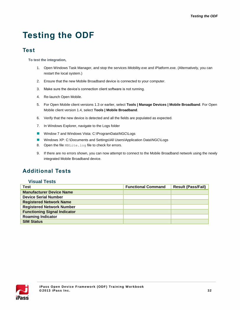
Additional Tests
Visual Tests Test Functional Command Result (Pass/Fail)
Manufacturer Device Name
Device Serial Number
Registered Network Name
Registered Network Number
Functioning Signal Indicator
Roaming Indicator
SIM Status

33
Testing the ODF
iPass Open Device Framework (ODF) Train ing W orkbook
2013 iPass Inc. 33
Functional Tests
Ensure the proper functionality of the following by applying the appropriate SIM if required:
Test Result (Pass/Fail)
Device Arrival/Departure Detection
Device information
Device PIN Management
Enable Pin (PIN 1)
Change PIN to PIN 2
Disable PIN (PIN 2)
Enable PIN (PIN 2)
Change PIN to PIN 1
Disable PIN (PIN 1)
Network information
Network Type
Network Name
Rate Selection
2G
3G
Network Type Display
2G
3G
Connection to 2G Network
Connection to 3G Network
Knowledge Review Questions
1. What is the first step you should take before testing the ODF?
2. What is the name of the ODF log file and where do you find it?
3. What are three things you look for in a visual test?
4. What are three things you look for in a functional test?
34
Uploading and Deploying the ODF
iPass Open Device Framework (ODF) Train ing W orkbook
2013 iPass Inc. 34
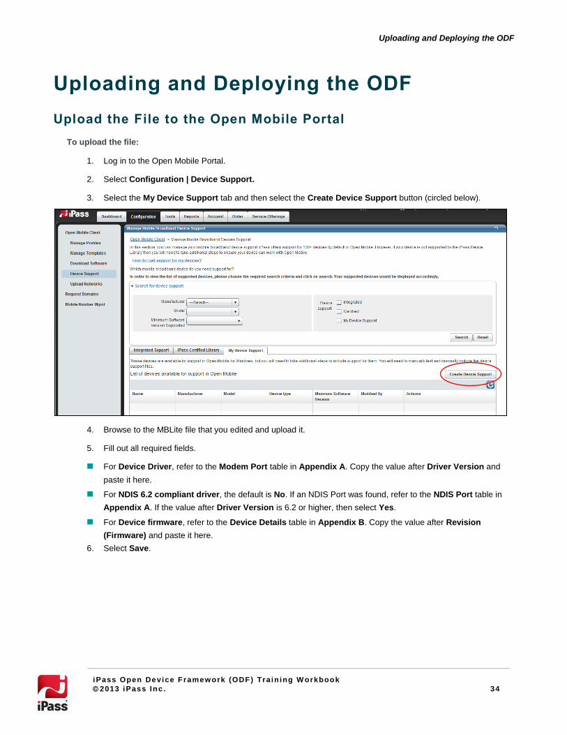
Uploading and Deploying the ODF
Upload the File to the Open Mobile Portal
To upload the file:
1. Log in to the Open Mobile Portal.
2. Select Configuration | Device Support.
3. Select the My Device Support tab and then select the Create Device Support button (circled below).
4. Browse to the MBLite file that you edited and upload it.
5. Fill out all required fields.
For Device Driver, refer to the Modem Port table in Appendix A. Copy the value after Driver Version and
paste it here.
For NDIS 6.2 compliant driver, the default is No. If an NDIS Port was found, refer to the NDIS Port table in
Appendix A. If the value after Driver Version is 6.2 or higher, then select Yes.
For Device firmware, refer to the Device Details table in Appendix B. Copy the value after Revision
(Firmware) and paste it here.
6. Select Save.

35
Uploading and Deploying the ODF
iPass Open Device Framework (ODF) Train ing W orkbook
2013 iPass Inc. 35
Deploy the ODF
To add the ODF integrated device to a profile:
1. Log in to the Open Mobile Portal.
2. Select Configuration | Manage Profiles.
3. Select Manage next to Profile to which you would like to add the device.
4. Next to Networks and Policies, select Configure (circled below).
5. Next to Open Device Framework, select Configure.
6. Select the ODF integrated device you would like to add to the profile.
7. Select Save.
Knowledge Review Questions
1. Under what tab do you find the Create Device Support button?
2. Where do you find the Device Driver?
3. Where do you find out if the NDIS port is 6.2-compliant?
4. Where do you find the Device Firmware?
5. What is the path you take to add the ODF device to a profile?

36
Troubleshooting
iPass Open Device Framework (ODF) Train ing W orkbook
2013 iPass Inc. 36
Troubleshooting
Support
If you are experiencing difficulties integrating the device and you cannot discover any errors in the XML, make sure you
fill out as much information as possible in Appendixes A, B, and C. Attach the completed Appendixes and a copy of your
XML template with any support case sent to Technical Support.
Tips
Produce one device, one definition at a time. The Open Mobile Portal sequences multiple Definitions, Device
ID and OS selections together into a Profile.
Manual Test Sets containing multiple devices must be sequenced by unique Device ID by-hand.
Multi-technology devices, such as GOBI, require a device definition (3001 & 3002) for each technology (GPRS
& CDMA), but only one device can be flagged as InUse in the Admin File, according to the device’s current
Firmware configuration.
Any upgrade of the device driver may necessitate a new ODF integration.
Make sure that the native connection manager is stopped, as it will interfere with Open Mobile.
Always try to integrate with the most up-to-date drivers.
MBLite.log
The MBLite.log records any errors in the ODF integration process. It is only written when there are errors. The log will be
found in the following locations:
Windows 7 and Windows Vista: C:\ProgramData\NGC\Logs
Windows XP: C:\Documents and Settings\All Users\Application Data\NGC\Logs
MBLite. log Fi le Format
Each line logged in MBLite.log file includes the following data:
Date
Time
Thread ID
Log Level
Module
File Name
Line Number
Failure Description
A sample log line is shown here.

37
Troubleshooting
iPass Open Device Framework (ODF) Train ing W orkbook
2013 iPass Inc. 37
09/01/2010 18:28:18.624 2380 ERROR MBLiteGPRS MBLiteGPRS.cpp 183 Failed to load database file
C:\Program Files\iPass\Open Mobile\MBLiteGPRS.xml.
If the text is long, it may be pushed into the next line.
Because Open Mobile may check the same functionality up to 3 times, a single error may include up to three entries in the log file.
Error Messages
These error messages may be encountered during the integration process.
Message Explanation
Failed to load database file C:\Program Files\iPass\Open Mobile\MBLite*.xml.
Check the file’s XML. You can verify it using ODFVerifier.html (see page 31), or simply review the XML in a browser or with an XML editor.
Default implementation of functionality "<Functionality>" has failed. Please try after including the XML block
<Functionality> in MBLiteGPRS.xml file. Please refer to the
User Guide for more information.
The device is not responding to the standard AT command for that functionality. Copy the failed functionality’s entire XML block from the long form MBLiteGPRS.xml and include it within
<DeviceFunctionality> XML node of your ODF template.
Now audit the device and use the device manufacturer’s list of proprietary AT Commands to find an alternate AT command.
Configure the values within <ResponseHeader> and <ResponseParser> XML blocks for the new AT command.
AT command <Command> specified in <Command1> for
functionality <Functionality> has failed. Please try an
alternate AT command. Please refer to the User Guide for more information.
The device is not responding to the standard AT command for that functionality. Copy the failed functionality’s entire XML block from the long form
MBLiteGPRS.xml and include it within
<DeviceFunctionality> XML node of your ODF template.
Now audit the device and use the device manufacturer’s list of proprietary AT Commands to find an alternate AT command.
Configure the values within <ResponseHeader> and <ResponseParser> XML blocks for the new AT command.
In <Functionality> XML element for Hardware Serial
Number functionality, AT command in <Command1> element
is missing. Please enter valid info in MBLite*.xml. Please
refer to the User Guide for more information.
An AT command has not been provided within the AT command node <ATCommand> for the named
functionality.
Check if the XML node <ATCommand> has been included
within the <Command1> XML block. Also check if a valid
AT command has been specified within <ATCommand>
XML node.
In <HwSerialNumber> XML element for Hardware Serial
Number functionality, <Parse1> XML element under
<Command1> is either missing or invalid. Please refer to the
User Guide for more information.
The parsing configuration information for an output item (specified in <Parse1>) for <Command1> in functionality
<HwSerialNumber> has been entered incorrectly (or
not specified at all).
Valid output parsing information specified under
<Command1> of <HwSerialNumber> functionality

38
Troubleshooting
iPass Open Device Framework (ODF) Train ing W orkbook
2013 iPass Inc. 38
follows:
<ResponseParser>
<Parse1 Type="string" Location="0"/>
</ResponseParser>
When copying the entire functionality XML block for an AT Command, make sure that the entire block is copied and nothing is left out. Removing any of the <ParseX>
XML nodes would constitute an invalid parse configuration setting.
Response header string "<string>" specified in
<Header1> XML node (enclosed within <ResponseHeader>
which in turn is enclosed) within <Command1> for
functionality <Functionality> was found to be invalid.
Please specify a valid response header string. In case you are not sure of the valid response header string for an AT
command, <Header1> XML node for an AT command may
be left empty in which case, response header if present in the AT command response string will be clipped off by default. Please refer to the User Guide for more information.
An invalid response header string has been specified for an AT command. While specifying an alternate AT command for one of the functionalities, you might have forgotten to update the response header string.
For few of the AT commands, the output response may contain a header string which corresponds to the issued AT command. This response header string must be removed before extracting the required information from the AT command response string. A valid response header string must be added by parsing the required information.
When a response header string mismatch is found, it is reported as an error and results in a functionality failure.
To determine the correct response header string for the AT command, issue the AT command to the device manually using SerialTerm. The response header string is the substring that appears to the left of the colon in the output response string.
If you are not able to determine the response header string for an AT command, then you can leave the <Header1> XML node empty.
Not all AT commands may return a response containing a header string associated with it. In such cases, the response header string if specified within <Header1> is simply ignored.
Detection Failure
After your integration is complete, your device may not be detected by Open Mobile. There are a number of reasons why
this may be the case.
Log File: Check the MBLite.log for errors that may be causing detection to fail.
Full Functionality: When a device is first connected to the computer or it returns from Standby or Sleep mode, it
may not be fully functional. A device may take a few moments for full functionality. Any queries for device or
network-related information may fail, and these failures are logged in MBLite.log.
Device Drivers: Confirm that the drivers for the device are installed by exiting from Open Mobile and
confirming a successful connection with the native client software.
Native Connection Client: Make sure the native connection client is closed. Open Mobile will not be able to use
the modem port if any native client is running.
XML Node Values: Incorrect values for XML nodes may cause issues.
Alternate Primary Port: The device may fail to respond with the standard modem port, in which case an

39
Troubleshooting
iPass Open Device Framework (ODF) Train ing W orkbook
2013 iPass Inc. 39
alternate AT Command port is to be specified as the primary port by including the < AdditionalPort> XML
node. See the Primary Port section on page 19. This behavior is generally observed in GPRS/GSM devices
belonging to the Sierra family.
Baud Rate: The Modem Port or Additional Port may respond only at a particular baud rate. Baud rate in bits per
second can be specified in the <BaudRate> XML node in MBLite*.xml. Correct Baud rate for a device can
be determined by either the device documentation or trial and error through SerialTerm. See the Primary Port
section on page 19.
HyperTerminal: make sure that HyperTerminal has been closed. Open Mobile cannot communicate with the
COM port if HyperTerminal is already connected to the device on that port.
Restart: make sure you have restarted Open Mobile by exiting the application and then re-launching it.
Resuming from Sleep Mode: In some cases, after resuming from sleep/hibernation, a device that has been ODF integrated with Open Mobile may be incorrectly detected as being fully integrated. Sample ODF files (SampleMBLiteGprs.xml and SampleMBLiteCdma.xml) contain default resume delay of 10 secs. To resolve this, try increasing the resume delay interval in the ODF file to 30 seconds.
Verification Failure
Although the verify*.html files verify the structure of the XML, verification will not determine whether the settings for
a given device is correct.
Functionality Failure
When a manufacturer’s implementation of an AT command differs from a default AT command, Open Mobile may detect
the device, but one or more functionalities may fail. Such failures would be logged and may require additional steps on your
part. Refer to the manufacturer's AT command implementation for the specific functionality.
In a few Huawei devices, when incorrect AT commands are issued, instead of logging an error, the string COMMAND NOT SUPPORTED is returned and displayed in Open Mobile.
To resolve functionality failure,
1. Using an XML editor, open your ODF template.
2. Open the long form MBLite.xml file.
3. Copy the entire XML block corresponding to the AT Command functionality that has failed.
4. Paste the copied functionality XML block with the <DeviceFunctionality> XML node of your ODF
template.
5. Modify the AT command to match the manufacturer's AT command implementation for the specific
functionality.
6. Save the file and close it.
7. Launch VerifyMBLite*.html to ensure that there are no errors in formatting.
8. Start Open Mobile to verify that the functionality works, and check the MBLite.log file for any error
messages.

40
Troubleshooting
iPass Open Device Framework (ODF) Train ing W orkbook
2013 iPass Inc. 40
Knowledge Review Questions
1. How do you create and ODF integration for a multi-technology device (like GOBI)?
2. List three things you may find in the MBLite log file.
3. If you see the error message, Failed to load database file C:\Program Files\iPass\Open
Mobile\MBLite*.xml. what should you do?
4. What are four things that may cause a detection failure?
5. How do you resolve a functionality failure for a particular AT command?

41
Appendix A: Port Details
iPass Open Device Framework (ODF) Train ing W orkbook
2013 iPass Inc. 41
Appendix A: Port Details Please print this Appendix or copy it into a new document so that you can fill it out as you audit the device. When you
have finished the ODF integration please send the completed Appendix to your Help Desk or Sales Engineer.
Modem Port
Detail Value
COM Port
Driver Version
Device description
Device Instance Path
Hardware Ids
NDIS Port (If Found)
Detail Value
Driver Version
Device description
Device Instance Path
Hardware Ids
Additional Port(S) (If Found)
Detail Value
COM Port
Device description
Device Instance Path
Hardware Ids
Detail Value
COM Port
Device description
Device Instance Path
Hardware Ids

42
Appendix B: Audit Information
iPass Open Device Framework (ODF) Train ing W orkbook
2013 iPass Inc. 42
Appendix B: Audit Information Please print this Appendix or copy it into a new document so that you can fill it out as you audit the device. When you
have finished the ODF integration please send the completed Appendix to your Help Desk or Sales Engineer.
Device Information
In the following table please include all of the information you can gather from the box and the Mobile Broadband Card.
Attribute Value
3G Technology
Brand Name
Model
Network (intended for use)
Any other information:
Manufacturer and Model
Use the values in the following table to complete the AdminWWDevices XML file.
Detail AT Command Value
Manufacturer AT+GMI
Model AT+GMM
Device Details
Connect to the Primary Port with SerialTerm and enter ATI to fill out the table below. For any Attribute that does not
appear, use an alternative AT Command (included in the table) to find the Value.
Attribute Alternative AT Command Value
Manufacturer: AT+GMI AT!UDINFO?
Model: AT+GMM
Revision: (Firmware)
AT+GMR
IMEI: AT+CGSN AT+GSN AT!GRELIMEI
Capabilities: AT+GCAP
43
Appendix B: Audit Information
iPass Open Device Framework (ODF) Train ing W orkbook
2013 iPass Inc. 43
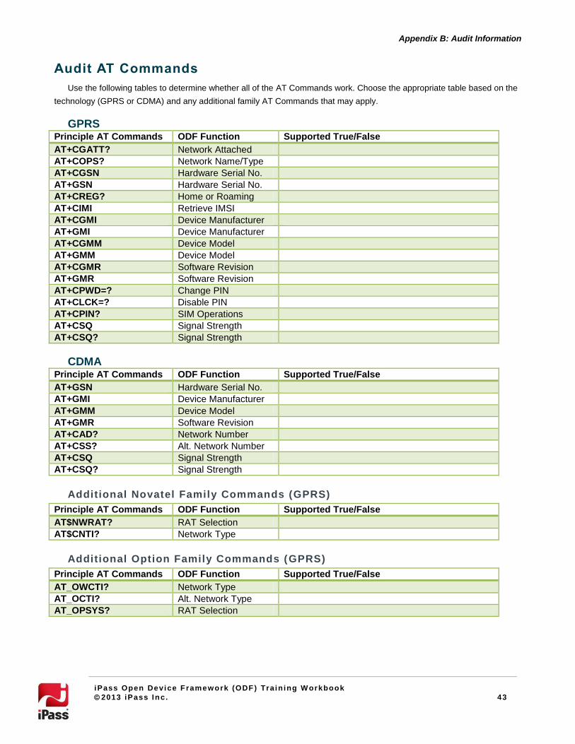
Audit AT Commands
Use the following tables to determine whether all of the AT Commands work. Choose the appropriate table based on the
technology (GPRS or CDMA) and any additional family AT Commands that may apply.
GPRS Principle AT Commands ODF Function Supported True/False
AT+CGATT? Network Attached
AT+COPS? Network Name/Type
AT+CGSN Hardware Serial No.
AT+GSN Hardware Serial No.
AT+CREG? Home or Roaming
AT+CIMI Retrieve IMSI
AT+CGMI Device Manufacturer
AT+GMI Device Manufacturer
AT+CGMM Device Model
AT+GMM Device Model
AT+CGMR Software Revision
AT+GMR Software Revision
AT+CPWD=? Change PIN
AT+CLCK=? Disable PIN
AT+CPIN? SIM Operations
AT+CSQ Signal Strength
AT+CSQ? Signal Strength
CDMA Principle AT Commands ODF Function Supported True/False
AT+GSN Hardware Serial No.
AT+GMI Device Manufacturer
AT+GMM Device Model
AT+GMR Software Revision
AT+CAD? Network Number
AT+CSS? Alt. Network Number
AT+CSQ Signal Strength
AT+CSQ? Signal Strength
Additional Novatel Family Commands (GPRS)
Principle AT Commands ODF Function Supported True/False
AT$NWRAT? RAT Selection
AT$CNTI? Network Type
Additional Option Family Commands (GPRS)
Principle AT Commands ODF Function Supported True/False
AT_OWCTI? Network Type
AT_OCTI? Alt. Network Type
AT_OPSYS? RAT Selection

44
Appendix B: Audit Information
iPass Open Device Framework (ODF) Train ing W orkbook
2013 iPass Inc. 44
Additional Huawei Family Commands (GPRS) Principle AT Commands ODF Function Supported True/False
AT^SYSCFG? RAT Selection
AT^SYSINFO Network Type
Additional Sierra Family Commands (GPRS) Principle AT Commands ODF Function Supported True/False
AT!SELRAT? RAT Selection
AT!GETRAT? CURRENT RAT Mode
Additional Ericsson Family Commands (GPRS) Principle AT Commands ODF Function Supported True/False
AT*ERINFO? Network Type
AT+CFUN=? RAT Selection
AT+CFUN? RAT Selection
List All Commands
Connect to the Primary Port with SerialTerm and issue List All Command. Try AT+CLAC or AT&V (whichever is
supported) to receive a list of all supported AT Commands and record the information in the box below (either paste a
screenshot or enter the result manually).

45
Appendix C: XML Reference
iPass Open Device Framework (ODF) Train ing W orkbook
2013 iPass Inc. 45
Appendix C: XML Reference Please print this Appendix or copy it into a new document so that you can fill it out before you edit the XML files. When
you have finished the ODF integration please send the completed Appendix to your Help Desk or Sales Engineer.
XML Format
Before entering any values in the tables in this appendix, make sure that they are formatted for XML. This means that
ampersands (&) become “&”.
For example: “vid_XXXX&pid_YYYY&mi_ZZ” should be entered as “vid_XXXX&pid_YYYY&mi_ZZ”.
AdminWWDevices
Choose the appropriate template based on the technology (GPRS or CDMA).
XML Tag Description Value
<wwdfdb:Device id="3001"> Device ID (between 3001 and 4000) 3001
<wwdfdb:Mfg> Manufacturer (see pg. 26)
<wwdfdb:Model> Model (see pg. 26)
MBLite: Device ID
XML Tag Description Value
<Device id="3001"> Device ID (between 3001 and 4000) 3001
MBLite: Ports
Modem Port
Before filling out the table below, review the description on page 13.
XML Tag Description Value
<ModemPort PrimaryPort =
"[true/false]">.
Is the Modem Port the Primary Port:
true or false?
<PortName> Device Description (pg. 25)
<PnPEnum> From the Device Instance Path (pg. 25)
<PnPID> From the Device Instance Path (pg. 25)

46
Appendix C: XML Reference
iPass Open Device Framework (ODF) Train ing W orkbook
2013 iPass Inc. 46
Additional Port (AT Command Port, If Found)
Before filling out the table below, review the description on page 14.
XML Tag Description Value
<AdditionalPort PrimaryPort =
"[true/false]">.
Is this the Primary Port: true or false?
<PortName> Device Description (pg. 25)
<PnPEnum> From the Device Instance Path (pg. 25)
<PnPID> From the Device Instance Path (pg. 25)
NDIS Port (If Found)
Before filling out the table below, review the description on page 15.
XML Tag Description Value
<PortName> Device Description (pg. 25)
<PnPEnum> From the Device Instance Path (pg. 25)
<PnPID> From the Device Instance Path (pg. 25)
MBLite: DeviceInfo
Enter the same data here as you entered for AdminWWDevices.
XML Tag Description Value
<Manufacturer> Manufacturer (see pg. 26)
<Model> Model (see pg. 26)
47
Appendix C: XML Reference
iPass Open Device Framework (ODF) Train ing W orkbook
2013 iPass Inc. 47
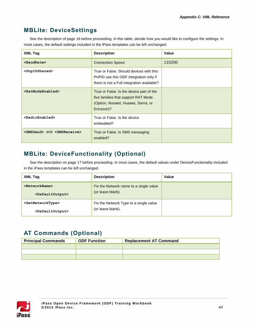
MBLite: DeviceSettings
See the description of page 16 before proceeding. In this table, decide how you would like to configure the settings. In
most cases, the default settings included in the iPass templates can be left unchanged.
XML Tag Description Value
<BaudRate> Connection Speed 115200
<PnpIDShared> True or False. Should devices with this
PnPID use this ODF integration only if
there is not a Full integration available?
<RatModeEnabled> True or False. Is the device part of the
five families that support RAT Mode
(Option, Novatel, Huawei, Sierra, or
Ericsson)?
<RadioEnabled> True or False. Is the device
embedded?
<SMSSend> and <SMSReceive> True or False. Is SMS messaging
enabled?
MBLite: DeviceFunctionality (Optional)
See the description on page 17 before proceeding. In most cases, the default values under DeviceFunctionality included
in the iPass templates can be left unchanged.
XML Tag Description Value
<NetworkName>
<DefaultOutput>
Fix the Network name to a single value
(or leave blank).
<GetNetworkType>
<DefaultOutput>
Fix the Network Type to a single value
(or leave blank).
AT Commands (Optional)
Principal Commands ODF Function Replacement AT Command
48
Appendix D: AT Commands
iPass Open Device Framework (ODF) Train ing W orkbook
2013 iPass Inc. 48
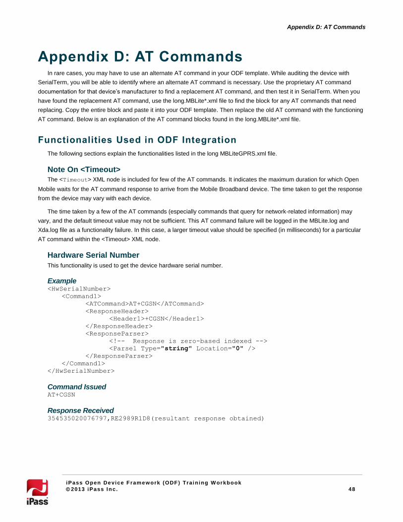
Appendix D: AT Commands In rare cases, you may have to use an alternate AT command in your ODF template. While auditing the device with
SerialTerm, you will be able to identify where an alternate AT command is necessary. Use the proprietary AT command
documentation for that device’s manufacturer to find a replacement AT command, and then test it in SerialTerm. When you
have found the replacement AT command, use the long.MBLite*.xml file to find the block for any AT commands that need
replacing. Copy the entire block and paste it into your ODF template. Then replace the old AT command with the functioning
AT command. Below is an explanation of the AT command blocks found in the long.MBLite*.xml file.
Functionalities Used in ODF Integration
The following sections explain the functionalities listed in the long MBLiteGPRS.xml file.
Note On <Timeout>
The <Timeout> XML node is included for few of the AT commands. It indicates the maximum duration for which Open
Mobile waits for the AT command response to arrive from the Mobile Broadband device. The time taken to get the response
from the device may vary with each device.
The time taken by a few of the AT commands (especially commands that query for network-related information) may
vary, and the default timeout value may not be sufficient. This AT command failure will be logged in the MBLite.log and
Xda.log file as a functionality failure. In this case, a larger timeout value should be specified (in milliseconds) for a particular
AT command within the <Timeout> XML node.
Hardware Serial Number
This functionality is used to get the device hardware serial number.
Example <HwSerialNumber>
<Command1>
<ATCommand>AT+CGSN</ATCommand>
<ResponseHeader>
<Header1>+CGSN</Header1>
</ResponseHeader>
<ResponseParser>
<!-- Response is zero-based indexed -->
<Parse1 Type="string" Location="0" />
</ResponseParser>
</Command1>
</HwSerialNumber>
Command Issued AT+CGSN
Response Received 354535020076797,RE2989R1D8(resultant response obtained)
49
Appendix D: AT Commands
iPass Open Device Framework (ODF) Train ing W orkbook
2013 iPass Inc. 49
Description
If present in the output response string, the header string is removed. The <Parse1> XML node is configured to extract
the 0th item (items are separated by a comma) in the output response string. The extracted item is the string corresponding
to the device Hardware serial number.
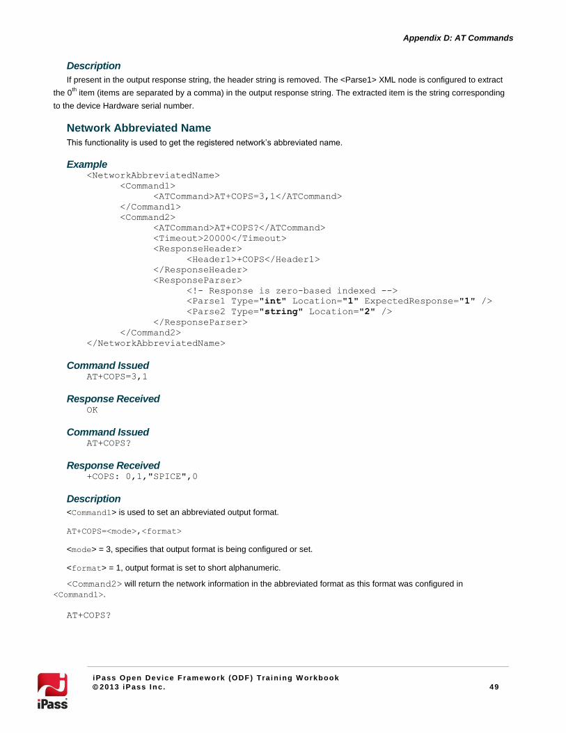
Network Abbreviated Name
This functionality is used to get the registered network’s abbreviated name.
Example <NetworkAbbreviatedName>
<Command1>
<ATCommand>AT+COPS=3,1</ATCommand>
</Command1>
<Command2>
<ATCommand>AT+COPS?</ATCommand>
<Timeout>20000</Timeout>
<ResponseHeader>
<Header1>+COPS</Header1>
</ResponseHeader>
<ResponseParser>
<!- Response is zero-based indexed -->
<Parse1 Type="int" Location="1" ExpectedResponse="1" />
<Parse2 Type="string" Location="2" />
</ResponseParser>
</Command2>
</NetworkAbbreviatedName>
Command Issued AT+COPS=3,1
Response Received OK
Command Issued AT+COPS?
Response Received +COPS: 0,1,"SPICE",0
Description
<Command1> is used to set an abbreviated output format.
AT+COPS=<mode>,<format>
<mode> = 3, specifies that output format is being configured or set.
<format> = 1, output format is set to short alphanumeric.
<Command2> will return the network information in the abbreviated format as this format was configured in
<Command1>.
AT+COPS?
50
Appendix D: AT Commands
iPass Open Device Framework (ODF) Train ing W orkbook
2013 iPass Inc. 50
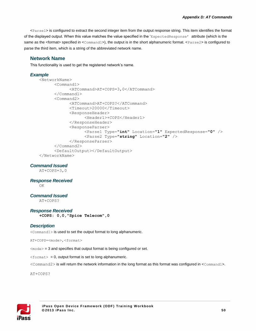
<Parse1> is configured to extract the second integer item from the output response string. This item identifies the format
of the displayed output. When this value matches the value specified in the ‘ExpectedResponse’ attribute (which is the
same as the <format> specified in <Command1>), the output is in the short alphanumeric format. <Parse2> is configured to
parse the third item, which is a string of the abbreviated network name.
Network Name
This functionality is used to get the registered network’s name.
Example <NetworkName>
<Command1>
<ATCommand>AT+COPS=3,0</ATCommand>
</Command1>
<Command2>
<ATCommand>AT+COPS?</ATCommand>
<Timeout>20000</Timeout>
<ResponseHeader>
<Header1>+COPS</Header1>
</ResponseHeader>
<ResponseParser>
<Parse1 Type="int" Location="1" ExpectedResponse="0" />
<Parse2 Type="string" Location="2" />
</ResponseParser>
</Command2>
<DefaultOutput></DefaultOutput>
</NetworkName>
Command Issued AT+COPS=3,0
Response Received OK
Command Issued AT+COPS?
Response Received +COPS: 0,0,"Spice Telecom",0
Description
<Command1> is used to set the output format to long alphanumeric.
AT+COPS=<mode>,<format>
<mode> = 3 and specifies that output format is being configured or set.
<format> = 0, output format is set to long alphanumeric.
<Command2> is will return the network information in the long format as this format was configured in <Command1>.
AT+COPS?

51
Appendix D: AT Commands
iPass Open Device Framework (ODF) Train ing W orkbook
2013 iPass Inc. 51
<Parse1> is configured to extract the second integer item from the output response string. This item identifies the format
of the output. When this value matches the value specified in the ‘ExpectedResponse’ attribute (same as the <format>
specified in <Command1>), the output is the long alphanumeric format. <Parse2> is configured to parse the third item,
which is a string of the network name in long format.
If a device fails to respond to the standard AT command used to query for network name (and if no alternate AT
commands are known), then a string may be specified in the <DefaultOutput> node. The specified string will be
considered the current network name.
Network Number
This functionality is used to get the registered network number.
Example
<NetworkNumber>
<Command1>
<ATCommand>AT+COPS=3,2</ATCommand>
</Command1>
<Command2>
<ATCommand>AT+COPS?</ATCommand>
<Timeout>20000</Timeout>
<ResponseHeader>
<Header1>+COPS</Header1>
</ResponseHeader>
<ResponseParser>
<!- Response is zero-based indexed -->
<Parse1 Type="int" Location="1" ExpectedResponse="2" />
<Parse2 Type="string" Location="2" />
</ResponseParser>
</Command2>
</NetworkNumber>
Command Issued AT+COPS=3,2
Response Received OK
Command Issued AT+COPS?
Response Received +COPS: 0,2,"40444",0
Description
<Command1> sets the output network information to numeric format.
AT+COPS=<mode>,<format>
<mode> = 3 and specifies that output format is being configured/set.
<format> = 2, output format set to numeric.
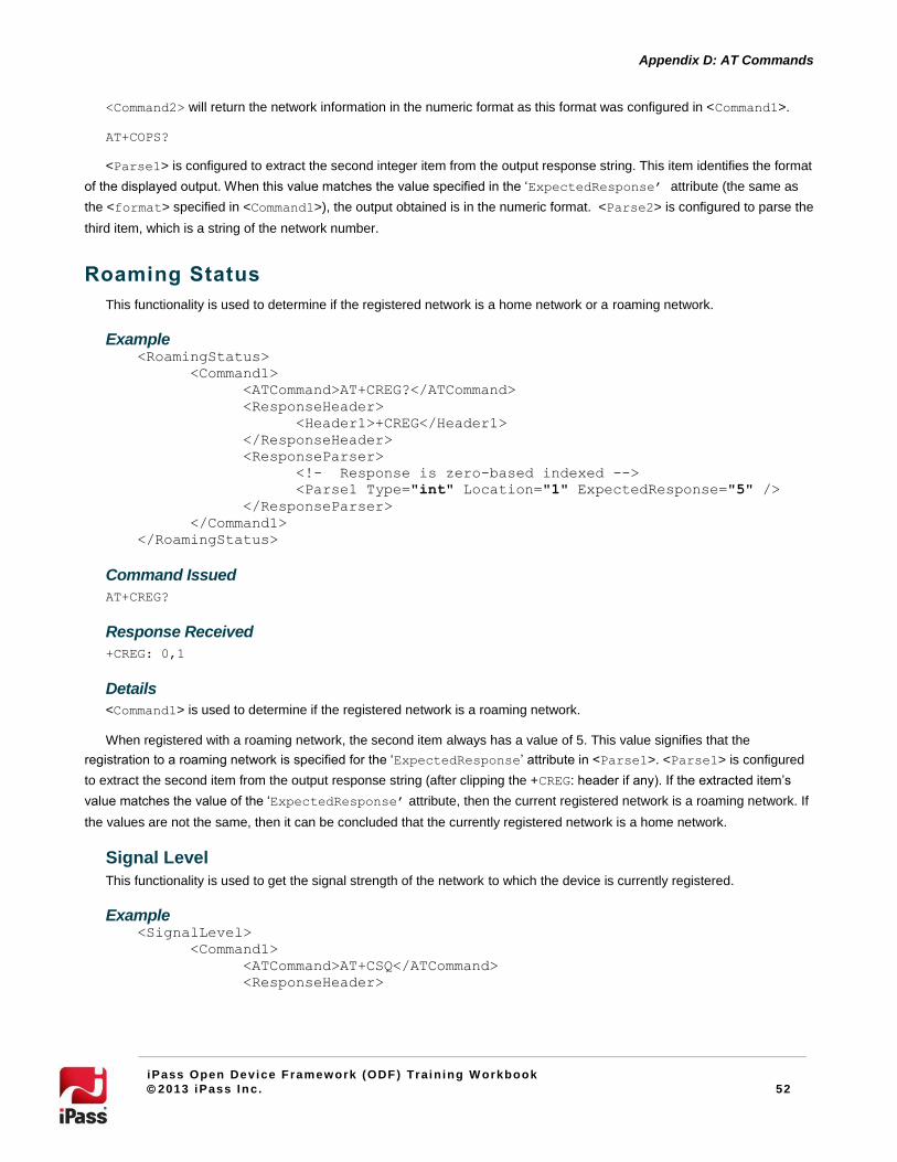
52
Appendix D: AT Commands
iPass Open Device Framework (ODF) Train ing W orkbook
2013 iPass Inc. 52
<Command2> will return the network information in the numeric format as this format was configured in <Command1>.
AT+COPS?
<Parse1> is configured to extract the second integer item from the output response string. This item identifies the format
of the displayed output. When this value matches the value specified in the ‘ExpectedResponse’ attribute (the same as
the <format> specified in <Command1>), the output obtained is in the numeric format. <Parse2> is configured to parse the
third item, which is a string of the network number.
Roaming Status
This functionality is used to determine if the registered network is a home network or a roaming network.
Example <RoamingStatus>
<Command1>
<ATCommand>AT+CREG?</ATCommand>
<ResponseHeader>
<Header1>+CREG</Header1>
</ResponseHeader>
<ResponseParser>
<!- Response is zero-based indexed -->
<Parse1 Type="int" Location="1" ExpectedResponse="5" />
</ResponseParser>
</Command1>
</RoamingStatus>
Command Issued
AT+CREG?
Response Received
+CREG: 0,1
Details
<Command1> is used to determine if the registered network is a roaming network.
When registered with a roaming network, the second item always has a value of 5. This value signifies that the
registration to a roaming network is specified for the ‘ExpectedResponse’ attribute in <Parse1>. <Parse1> is configured
to extract the second item from the output response string (after clipping the +CREG: header if any). If the extracted item’s
value matches the value of the ‘ExpectedResponse’ attribute, then the current registered network is a roaming network. If
the values are not the same, then it can be concluded that the currently registered network is a home network.
Signal Level
This functionality is used to get the signal strength of the network to which the device is currently registered.
Example <SignalLevel>
<Command1>
<ATCommand>AT+CSQ</ATCommand>
<ResponseHeader>
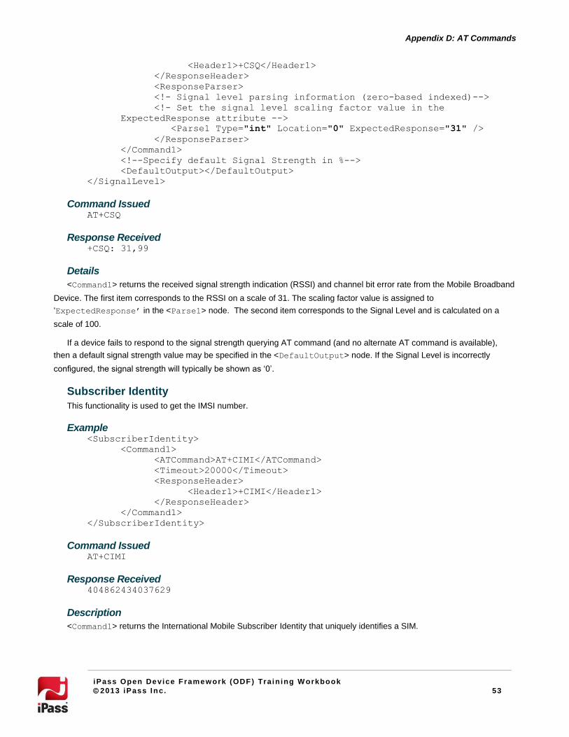
53
Appendix D: AT Commands
iPass Open Device Framework (ODF) Train ing W orkbook
2013 iPass Inc. 53
<Header1>+CSQ</Header1>
</ResponseHeader>
<ResponseParser>
<!- Signal level parsing information (zero-based indexed)-->
<!- Set the signal level scaling factor value in the
ExpectedResponse attribute -->
<Parse1 Type="int" Location="0" ExpectedResponse="31" />
</ResponseParser>
</Command1>
<!--Specify default Signal Strength in %-->
<DefaultOutput></DefaultOutput>
</SignalLevel>
Command Issued AT+CSQ
Response Received +CSQ: 31,99
Details
<Command1> returns the received signal strength indication (RSSI) and channel bit error rate from the Mobile Broadband
Device. The first item corresponds to the RSSI on a scale of 31. The scaling factor value is assigned to
‘ExpectedResponse’ in the <Parse1> node. The second item corresponds to the Signal Level and is calculated on a
scale of 100.
If a device fails to respond to the signal strength querying AT command (and no alternate AT command is available),
then a default signal strength value may be specified in the <DefaultOutput> node. If the Signal Level is incorrectly
configured, the signal strength will typically be shown as ‘0’.
Subscriber Identity
This functionality is used to get the IMSI number.
Example <SubscriberIdentity>
<Command1>
<ATCommand>AT+CIMI</ATCommand>
<Timeout>20000</Timeout>
<ResponseHeader>
<Header1>+CIMI</Header1>
</ResponseHeader>
</Command1>
</SubscriberIdentity>
Command Issued AT+CIMI
Response Received 404862434037629
Description
<Command1> returns the International Mobile Subscriber Identity that uniquely identifies a SIM.
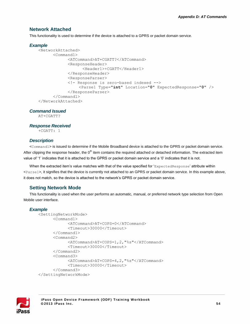
54
Appendix D: AT Commands
iPass Open Device Framework (ODF) Train ing W orkbook
2013 iPass Inc. 54
Network Attached
This functionality is used to determine if the device is attached to a GPRS or packet domain service.
Example <NetworkAttached>
<Command1>
<ATCommand>AT+CGATT?</ATCommand>
<ResponseHeader>
<Header1>+CGATT</Header1>
</ResponseHeader>
<ResponseParser>
<!- Response is zero-based indexed -->
<Parse1 Type="int" Location="0" ExpectedResponse="0" />
</ResponseParser>
</Command1>
</NetworkAttached>
Command Issued AT+CGATT?
Response Received +CGATT: 1
Description
<Command1> is issued to determine if the Mobile Broadband device is attached to the GPRS or packet domain service.
After clipping the response header, the 0th item contains the required attached or detached information. The extracted item
value of ‘1’ indicates that it is attached to the GPRS or packet domain service and a ‘0’ indicates that it is not.
When the extracted item’s value matches with that of the value specified for ‘ExpectedResponse’ attribute within
<Parse1>, it signifies that the device is currently not attached to an GPRS or packet domain service. In this example above,
it does not match, so the device is attached to the network’s GPRS or packet domain service.
Setting Network Mode
This functionality is used when the user performs an automatic, manual, or preferred network type selection from Open
Mobile user interface.
Example <SettingNetworkMode>
<Command1>
<ATCommand>AT+COPS=0</ATCommand>
<Timeout>30000</Timeout>
</Command1>
<Command2>
<ATCommand>AT+COPS=1,2,"%s"</ATCommand>
<Timeout>30000</Timeout>
</Command2>
<Command3>
<ATCommand>AT+COPS=4,2,"%s"</ATCommand>
<Timeout>30000</Timeout>
</Command3>
</SettingNetworkMode>

55
Appendix D: AT Commands
iPass Open Device Framework (ODF) Train ing W orkbook
2013 iPass Inc. 55
Command Issued
When a Hutch network (N/W number 40486) is to be manually selected, the resultant AT command issued to the device
follows:
AT+COPS=1,2,"40486"
Description
<Command1>, <Command2> and <Command3> for functionality <SettingNetworkMode> perform operator selection
operations.
The AT command specified within <Command1> is used to select an operator automatically. The AT command specified
within <Command2> and <Command3> are for the format
AT+COPS=<mode>,<format>,”Network Operator”.
In <Command2>, the <mode> is set to 1 signifying that a network is manually selected. The <format> is set to 2,
indicating that the manually selected network information is specified in numeric format (%s in <Command2> and
<Command3> will be replaced with the manually selected network’s network number).
In <Command3>, the <mode> is set to 4, which indicates that if manual selection fails, automatic mode is entered. The
<format> is set to 2, which implies that the network has to be manually selected and will be replaced by %s within the AT
command, specifying numeric format.
AT commands specified within <Command1> and <Command2> are used to switch between automatic and manually
selected network modes respectively. AT command specified within <Command3> is currently reserved and is never
executed.
Device Manufacturer
This functionality is used to get the device manufacturer.
Example 1 <Manufacturer>
<Command1>
<ATCommand>AT+GMI</ATCommand>
<ResponseHeader>
<Header1>+GMI</Header1>
</ResponseHeader>
</Command1>
</Manufacturer>
Description
<Command1> is queries for the device manufacturer information.
An alternate AT command set used with GPRS devices is given below.
Example 2
<Command1>
<ATCommand>AT+CGMI</ATCommand>
<ResponseHeader>
<Header1>+CGMI</Header1>
</ResponseHeader>
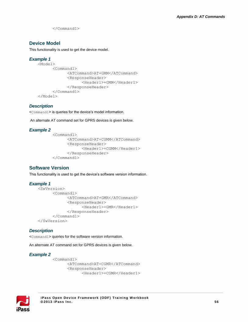
56
Appendix D: AT Commands
iPass Open Device Framework (ODF) Train ing W orkbook
2013 iPass Inc. 56
</Command1>
Device Model
This functionality is used to get the device model.
Example 1 <Model>
<Command1>
<ATCommand>AT+GMM</ATCommand>
<ResponseHeader>
<Header1>+GMM</Header1>
</ResponseHeader>
</Command1>
</Model>
Description
<Command1> is queries for the device’s model information.
An alternate AT command set for GPRS devices is given below.
Example 2 <Command1>
<ATCommand>AT+CGMM</ATCommand>
<ResponseHeader>
<Header1>+CGMM</Header1>
</ResponseHeader>
</Command1>
Software Version
This functionality is used to get the device’s software version information.
Example 1 <SwVersion>
<Command1>
<ATCommand>AT+GMR</ATCommand>
<ResponseHeader>
<Header1>+GMR</Header1>
</ResponseHeader>
</Command1>
</SwVersion>
Description
<Command1> queries for the software version information.
An alternate AT command set for GPRS devices is given below.
Example 2 <Command1>
<ATCommand>AT+CGMR</ATCommand>
<ResponseHeader>
<Header1>+CGMR</Header1>
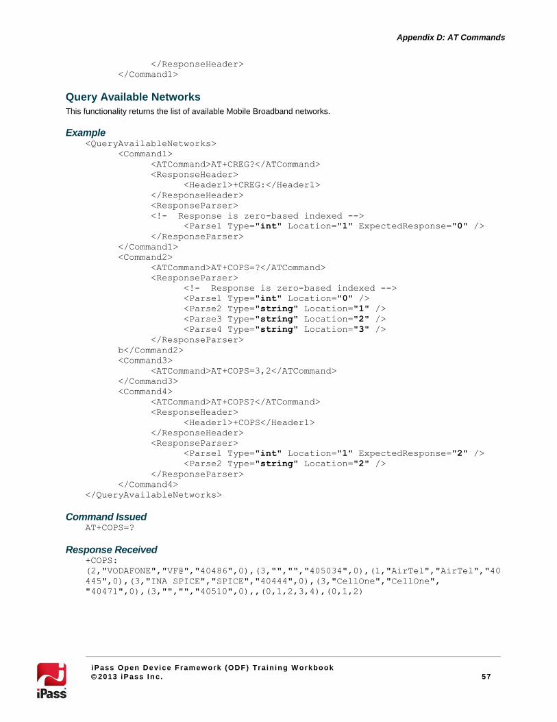
57
Appendix D: AT Commands
iPass Open Device Framework (ODF) Train ing W orkbook
2013 iPass Inc. 57
</ResponseHeader>
</Command1>
Query Available Networks
This functionality returns the list of available Mobile Broadband networks.
Example <QueryAvailableNetworks>
<Command1>
<ATCommand>AT+CREG?</ATCommand>
<ResponseHeader>
<Header1>+CREG:</Header1>
</ResponseHeader>
<ResponseParser>
<!- Response is zero-based indexed -->
<Parse1 Type="int" Location="1" ExpectedResponse="0" />
</ResponseParser>
</Command1>
<Command2>
<ATCommand>AT+COPS=?</ATCommand>
<ResponseParser>
<!- Response is zero-based indexed -->
<Parse1 Type="int" Location="0" />
<Parse2 Type="string" Location="1" />
<Parse3 Type="string" Location="2" />
<Parse4 Type="string" Location="3" />
</ResponseParser>
b</Command2>
<Command3>
<ATCommand>AT+COPS=3,2</ATCommand>
</Command3>
<Command4>
<ATCommand>AT+COPS?</ATCommand>
<ResponseHeader>
<Header1>+COPS</Header1>
</ResponseHeader>
<ResponseParser>
<Parse1 Type="int" Location="1" ExpectedResponse="2" />
<Parse2 Type="string" Location="2" />
</ResponseParser>
</Command4>
</QueryAvailableNetworks>
Command Issued AT+COPS=?
Response Received +COPS:
(2,"VODAFONE","VF@","40486",0),(3,"","","405034",0),(1,"AirTel","AirTel","40
445",0),(3,"INA SPICE","SPICE","40444",0),(3,"CellOne","CellOne",
"40471",0),(3,"","","40510",0),,(0,1,2,3,4),(0,1,2)

58
Appendix D: AT Commands
iPass Open Device Framework (ODF) Train ing W orkbook
2013 iPass Inc. 58
Description
QueryAvailableNetworks functionality returns the list of available Mobile Broadband networks.
The AT command ‘AT+COPS=?’ specified within <Command2> returns the list of available Mobile Broadband networks.
As observed in the example above, each operator’s network information is enclosed in parentheses. One operator’s network
information set (such as: 2,"VODAFONE","VF@","40486",0) is considered at a time. Through the <Parse1> configuration in
<Command2>, the 0th
item (integer type) is extracted and this item contains the network status information. If a network
status is found to be forbidden, then that network is not considered at all.
For all non-forbidden networks, the network name, network abbreviated name, and network number are extracted
through the configuration in <Parse2>, <Parse3> and <Parse4> nodes respectively, and this network is included in the list
of available networks. Then, the next operator’s network information set is considered, and this process is continued until all
the information sets are exhausted.
AT commands specified in <Command3> and <Command4> are executed only when the currently registered network is
not included in the list of available networks. In such a case, the currently registered network information is queried using the
command specified in <Command3> and <Command4> and the required information is extracted (from the output response).
This network (with the extracted information) is added to the available networks list.
AT command specified in <Command1> is executed only for devices for which the flag value of ‘1’ is included.
AT command specified within <Command1> is used to determine if the device is registered to a network or not and this
check is performed before the query for available networks is carried out. When not registered, the registration check is
performed periodically, until the device registers to a Mobile Broadband network, or until the 30-second timeout elapses,
whichever occurs first.
AT Commands for the SIM Card
SIM Status
This functionality returns the current SIM status.
Example <samoIMStatus>
<Command1>
<ATCommand>AT+CPIN?</ATCommand>
<ResponseHeader>
<Header1>+CPIN</Header1>
<!- Header strings below used for comparison with AT
command response to determine the current SIM status -->
<Header2>PIN2</Header2>
<Header3>PIN</Header3>
<Header4>PUK2</Header4>
<Header5>PUK</Header5>
<Header6>READY</Header6>
</ResponseHeader>
</Command1>
</GetSIMStatus>
Command Issued AT+CPIN?

59
Appendix D: AT Commands
iPass Open Device Framework (ODF) Train ing W orkbook
2013 iPass Inc. 59
Response Received +CPIN: SIM PIN (Response when the SIM is PIN Locked)
Description
This functionality determines the device’s SIM status.
The AT command ‘AT+CPIN?’ specified within <ATCommand> node returns the SIM status. After clipping the header
string from the output response string, the output response string is compared with the pre-determined header strings (as
explained below) to determine the SIM status.
If the string specified in <Header2> (‘PIN2’) is not a subset of the output response string and string specified in
<Header3> (‘PIN’) is a subset of the output response string, the current SIM status is PIN Locked.
If the strings specified in <Header4> (‘PUK2’) or in <Header5> (‘PUK’) appear as substrings in the output response
string, the SIM status is PUK Locked.
If the strings specified in <Header6> (‘READY’) or in <Header2> (‘PIN2’) appear as substrings in the output response
string, the SIM status is in the Ready state (it is not in the SIM Locked or PUK Locked state).
Change SIM PIN
This functionality is used to change the PIN of the device’s SIM.
Example <ChangeSIMPin>
<Command1>
<ATCommand>AT+CPWD="SC","%s","%s"</ATCommand>
</Command1>
</ChangeSIMPin>
Command Issued AT+CPWD="SC","0000","1111" (0000 is the current SIM PIN and 1111 is the
newly assigned SIM PIN)
Response Received OK
Description
The <Command1> assigns a new PIN to the device’s SIM. In the AT command ‘AT+CPWD="SC","%s","%s’, the first
placeholder ‘%s’ gets replaced with the current PIN and the last ‘%s’ gets replaced with the newly assigned PIN as illustrated
in the example above.
Once configured successfully, the new PIN will be required to unlock the SIM.
Disable SIM PIN
This functionality disables the PIN for the device’s SIM.
Example <DisableSIMPin>
<Command1>
<ATCommand>AT+CLCK="SC",0,"%s"</ATCommand>
</Command1>

60
Appendix D: AT Commands
iPass Open Device Framework (ODF) Train ing W orkbook
2013 iPass Inc. 60
</DisableSIMPin>
Command Issued AT+CLCK="SC",0,"1111"(‘1111’ is the current SIM PIN)
Response Received OK
Description
The <Command1> disables the PIN. Once disabled, the device’s SIM will no longer prompt for a PIN.
The “SC” in the AT command (1st item) signifies that a PIN Lock related operation is being performed. A value of ‘0’
specified in the second item signifies that the SIM PIN Lock facility is to be disabled. The current PIN replaces the
placeholder identified by ‘%s’ above.
Enable SIM PIN
This functionality enables a PIN for the device’s SIM.
Example <EnableSIMPin>
<Command1>
<ATCommand>AT+CLCK="SC",1,"%s"</ATCommand>
</Command1>
</EnableSIMPin>
Command Issued AT+CLCK="SC",1,"1111"
Response Received OK
Description
The <Command1> enables a PIN for the device’s SIM. The “SC” in the AT command (1st item) signifies that a PIN Lock
related operation is being performed. A value of ‘1’ in the second item signifies that the PIN Lock for the SIM is enabled. The
placeholder string ‘%s’ is replaced by the PIN.
SIM Lock Status
This functionality determines whether or not the PIN Lock is enabled.
Example <SIMLockStatus>
<Command1>
<ATCommand>AT+CLCK="SC",2</ATCommand>
<ResponseHeader>
<Header1>+CLCK</Header1>
</ResponseHeader>
<ResponseParser>
<Parse1 Type="int" Location="0" />
</ResponseParser>
</Command1>
<Command2>
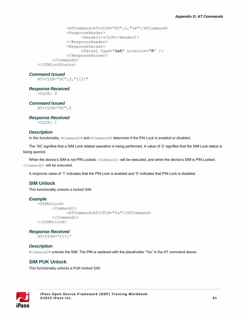
61
Appendix D: AT Commands
iPass Open Device Framework (ODF) Train ing W orkbook
2013 iPass Inc. 61
<ATCommand>AT+CLCK="SC",2,"%s"</ATCommand>
<ResponseHeader>
<Header1>+CLCK</Header1>
</ResponseHeader>
<ResponseParser>
<Parse1 Type="int" Location="0" />
</ResponseParser>
</Command2>
</SIMLockStatus>
Command Issued AT+CLCK="SC",2,"1111"
Response Received +CLCK: 0
Command Issued AT+CLCK="SC",2
Response Received +CLCK: 1
Description
In this functionality, <Command1> and <Command2> determine if the PIN Lock is enabled or disabled.
The “SC signifies that a SIM Lock related operation is being performed. A value of ‘2’ signifies that the SIM Lock status is
being queried.
When the device’s SIM is not PIN Locked, <Command1> will be executed, and when the device’s SIM is PIN Locked,
<Command2> will be executed.
A response value of ‘1’ indicates that the PIN Lock is enabled and ‘0’ indicates that PIN Lock is disabled.
SIM Unlock
This functionality unlocks a locked SIM.
Example <SIMUnlock>
<Command1>
<ATCommand>AT+CPIN="%s"</ATCommand>
</Command1>
</SIMUnlock>
Response Received AT+CPIN=”1111”
Description
<Command1> unlocks the SIM. The PIN is replaced with the placeholder “%s” in the AT command above.
SIM PUK Unlock
This functionality unlocks a PUK-locked SIM.

62
Appendix D: AT Commands
iPass Open Device Framework (ODF) Train ing W orkbook
2013 iPass Inc. 62
Example
<SIMPUKUnlock>
<Command1>
<ATCommand>AT+CPIN="%s","%s"</ATCommand>
</Command1>
</SIMPUKUnlock>
Response Received AT+CPIN="84129909",”1111” (PUK code and the new SIM PIN specified)
Description
<Command1> is called when the SIM is PUK Locked. A PIN enabled SIM enters a PUK Locked state when three
consecutive attempts are made to unlock an SIM with an incorrect PIN. The PUK code (an 8-digit number) is required to
unlock the SIM device, and this code may be provided by the operator.
In the AT command ‘AT+CPIN="%s","%s"’, the first placeholder %s gets replaced with the actual 8-digit PUK code and
the next placeholder %s gets replaced with the newly specified PIN.
SetRat Mode Functionality
SetRatMode is called when a Radio Access Technology (RAT) type is selected. The options available in Open Mobile
are: Automatic, 3G, and 2G. When Automatic is specified, the best available Radio Access Technology is selected.
As there are no generic AT commands for RAT mode selection operation, family-specific AT commands are used. RAT
Mode is currently supported for devices belonging to "Option", "Novatel", "Huawei", "Ericsson" and "Sierra" family only.
For a new device, the <SetRatMode> functionality may fail because the device no longer supports the AT command
(and the current AT command should be used in its place).
The SetRatMode functionality applicable for the selected device family is listed below.
Option Family Of Devices
This XML block included for SetRatMode functionality for devices belonging to Option family only.
Example <SetRatMode Family="Option">
<Command1>
<!--for automatic mode select-->
ATCommand>AT_OPSYS=5,4</ATCommand>
</Command1>
<Command2>
<!--to set mode to 3G mode only-->
<ATCommand>AT_OPSYS=1,4</ATCommand>
</Command2>
<Command3>
<!--to set to 2G mode only-->
<ATCommand>AT_OPSYS=0,4</ATCommand>
</Command3>
<Command4>
<!--for no change in mode-->
<ATCommand>AT_OPSYS=4,4</ATCommand>
</Command4>

63
Appendix D: AT Commands
iPass Open Device Framework (ODF) Train ing W orkbook
2013 iPass Inc. 63
</SetRatMode>
Description
The AT command specified within <Command1>, <Command2>, and <Command3> are used to select Automatic, 3G,
and 2G respectively. The AT command in <Command4> does not change the technology type. This option is reserved and is
not currently available in Open Mobile.
The AT command format is as follows: AT_OPSYS=<mode>,<domain>
Where the value assigned to <mode> determines the technology type selected:
5 for auto
1 for 3G mode
0 for 2G mode
4 for no change in mode
Huawei Family of Devices
This XML block is for Huawei family only.
Example <SetRatMode Family="Huawei">
<Command1>
<!-- for automatic mode select -->
<ATCommand>AT^SYSCFG=2,3,4F80380,2,4</ATCommand>
</Command1>
<Command2>
<!-- to set mode to 3G mode only -->
<ATCommand>AT^SYSCFG=14,3,4F80380,2,4</ATCommand>
</Command2>
<Command3>
<!-- to set to 2G mode only -->
<ATCommand>AT^SYSCFG=13,3,4F80380,2,4</ATCommand>
</Command3>
<Command4>
<!-- for no change in mode -->
<ATCommand>AT^SYSCFG=16,3,4F80380,2,4</ATCommand>
</Command4>
</SetRatMode>
Description
The AT command specified within <Command1>, <Command2>, and <Command3> are used to select Automatic, 3G,
and 2G respectively. The AT command in <Command4> does not change the technology type. This option is reserved and is
not currently available in Open Mobile.
AT command format is as follows: AT^SYSCFG=<mode>,<acqorder>,<band>,<roam>,<srvdomain>
Where the value assigned to <mode> determines the technology type selected:
2 for auto
14 for 3G mode
13 for 2G mode
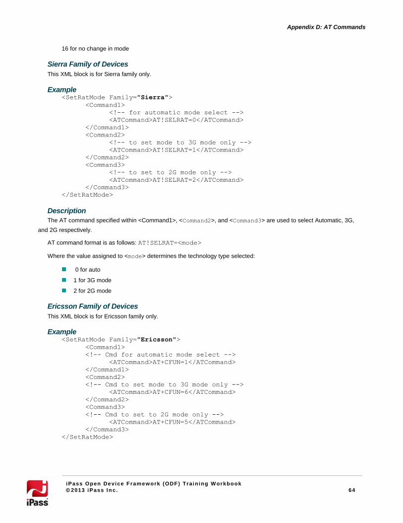
64
Appendix D: AT Commands
iPass Open Device Framework (ODF) Train ing W orkbook
2013 iPass Inc. 64
16 for no change in mode
Sierra Family of Devices
This XML block is for Sierra family only.
Example <SetRatMode Family="Sierra">
<Command1>
<!-- for automatic mode select -->
<ATCommand>AT!SELRAT=0</ATCommand>
</Command1>
<Command2>
<!-- to set mode to 3G mode only -->
<ATCommand>AT!SELRAT=1</ATCommand>
</Command2>
<Command3>
<!-- to set to 2G mode only -->
<ATCommand>AT!SELRAT=2</ATCommand>
</Command3>
</SetRatMode>
Description
The AT command specified within <Command1>, <Command2>, and <Command3> are used to select Automatic, 3G,
and 2G respectively.
AT command format is as follows: AT!SELRAT=<mode>
Where the value assigned to <mode> determines the technology type selected:
0 for auto
1 for 3G mode
2 for 2G mode
Ericsson Family of Devices
This XML block is for Ericsson family only.
Example <SetRatMode Family="Ericsson">
<Command1>
<!-- Cmd for automatic mode select -->
<ATCommand>AT+CFUN=1</ATCommand>
</Command1>
<Command2>
<!-- Cmd to set mode to 3G mode only -->
<ATCommand>AT+CFUN=6</ATCommand>
</Command2>
<Command3>
<!-- Cmd to set to 2G mode only -->
<ATCommand>AT+CFUN=5</ATCommand>
</Command3>
</SetRatMode>

65
Appendix D: AT Commands
iPass Open Device Framework (ODF) Train ing W orkbook
2013 iPass Inc. 65
Description
The AT command specified within <Command1>, <Command2>, and <Command3> are used to select Automatic, 3G,
and 2G respectively.
AT command format is as follows: AT+CFUN= <fun>
Where the value assigned to <fun> determines the technology type selected:
1 for auto
6 for 3G mode
5 for 2G mode
Novatel Family of Devices
This XML block is for Novatel family only.
Example <SetRatMode Family="Novatel">
<Command1>
<!—find current -->
<ATCommand>AT$NWRAT?</ATCommand>
<ResponseHeader>
<Header1>$NWRAT:</Header1>
</ResponseHeader>
<ResponseParser>
<!-- item corresponds to mode -->
<Parse1 Type="int" Location="0" />
<!-- item corresponds to domain -->
<Parse2 Type="int" Location="1" />
<!-- item corresponds to state -->
<Parse3 Type="int" Location="2" />
</ResponseParser>
</Command1>
<Command2>
<!- %i below will be replaced by current domain got by Command1 above
-->
<!-- for automatic mode select -->
<ATCommand>AT$NWRAT=0,%i</ATCommand>
</Command2>
<Command3>
<!-- to set mode to 3G mode only -->
<ATCommand>AT$NWRAT=2,%i</ATCommand>
</Command3>
<Command4>
<!-- to set to 2G mode only -->
<ATCommand>AT$NWRAT=1,%i</ATCommand>
</Command4>
</SetRatMode>
Description
<Command1> determines the current mode, domain, and state. The current domain has to be specified when selecting a
technology type, and in the above AT commands, the placeholder ‘%i’ gets replaced with the current domain from
<Command1>.

66
Appendix D: AT Commands
iPass Open Device Framework (ODF) Train ing W orkbook
2013 iPass Inc. 66
The AT commands specified in <Command2>, <Command3>, and <Command4> select Automatic, 3G, and 2G
respectively.
The AT command format is as follows: AT$NWRAT=<mode>,<domain>
The value assigned to <mode> determines the technology type selected:
0 for auto
2 for 3G mode
1 for 2G mode
Get Network Type Functionality
This functionality determines the network type. As there are no generic AT commands to determine the currently
registered network’s type, family-specific AT commands are used.
GetNetworkType functionality is currently supported for devices belonging to the Option, Novatel, Huawei, and Ericsson
families only.
For a new device, <GetNetworkType> functionality may fail because the device no longer supports old AT commands
(and the current AT command should be used in its place). If any of the AT command fails, then the default GPRS network
type is considered and returned by this functionality and the same will be displayed in Open Mobile.
For devices with no available commands to query for the current network type, the default network type of GPRS is used.
The default GPRS can be overridden by specifying a network type. When a Network Type is specified within
<DefaultOutput>, the specified Network Type is always considered. In such a scenario, AT command implementation of the
GetNetworkType functionality is simply ignored.
Valid network types that can be specified in the <DefaultOutput> for GSM/GPRS devices are: GPRS, EDGE, UMTS,
HSDPA, HSUPA, or HSPA.
Example1 <GetNetworkType>
<DefaultOutput>UMTS</DefaultOutput>
</GetNetworkType>
In Example1, UMTS is returned and displayed in Open Mobile as the current network type.
GetNetworkType functionality applicable for the selected device family is listed below.
Novatel Family of Devices
This XML block for devices belonging to Novatel family only.
Example <GetNetworkType Family="Novatel">
<!-- For Novatel family of devices-->
<Command1>
<ATCommand>AT$CNTI=0</ATCommand>
<ResponseHeader>
<Header1>$CNTI:</Header1>
</ResponseHeader>
<ResponseParser>
<!-- Response is zero-based indexed-->

67
Appendix D: AT Commands
iPass Open Device Framework (ODF) Train ing W orkbook
2013 iPass Inc. 67
<Parse1 Type="string" Location="1"/>
</ResponseParser>
</Command1>
<DefaultOutput></DefaultOutput>
</GetNetworkType>
Description
The above mentioned AT command is issued to the device and the response that is obtained is clipped of its header
string if any. The second item from the left (items are separated by ‘comma’) in the output response string is extracted as
configured in <Parse1>.This extracted item is a string that corresponds to the current network type and is translated to an
equivalent value that is understood by the Mobile Broadband module.
Option Family of Devices
This XML block is for devices belonging to Option family only.
Example <GetNetworkType Family="Option">
<Command1>
<ATCommand>AT+COPS?</ATCommand>
<ResponseHeader>
<Header1>+COPS:</Header1>
</ResponseHeader>
<ResponseParser>
<Parse1 Type="int" Location="3"/>
</ResponseParser>
</Command1>
<Command2>
<ATCommand>AT_OCTI?</ATCommand>
<ResponseHeader>
<Header1>_OCTI:</Header1>
</ResponseHeader>
<ResponseParser>
<!-- Response is zero-based indexed-->
<Parse1 Type="int" Location="0"/>
<Parse2 Type="int" Location="1"/>
</ResponseParser>
</Command2>
<Command3>
<ATCommand>AT+CGATT?</ATCommand>
<ResponseHeader>
<Header1>+CGATT</Header1>
</ResponseHeader>
<ResponseParser>
<Parse1 Type="int" Location="0" ExpectedResponse="0"/>
</ResponseParser>
</Command3>
<Command4>
<ATCommand>AT_OWCTI?</ATCommand>
<ResponseHeader>
<Header1>_OWCTI:</Header1>
</ResponseHeader>
<ResponseParser>

68
Appendix D: AT Commands
iPass Open Device Framework (ODF) Train ing W orkbook
2013 iPass Inc. 68
<Parse1 Type="int" Location="0"/>
</ResponseParser>
</Command4>
<DefaultOutput></DefaultOutput>
</GetNetworkType>
Description
When the AT command in <Command1> is issued, the fourth item in the output response string corresponds to the
current technology type (integer type) and is extracted through the <Parse1> configuration within <Command1>.
If the extracted item (as illustrated above) contains a value of ‘0’ or ‘1’, then it signifies that the current network is a 2G
network, and the AT command specified within <Command2> is executed to determine the 2G network type. The 2nd
item in
the output response string corresponds to the 2G Network Type and the <Parse2> node is configured to extract it. If a valid
2G network type is still not determined from <Command2>, a check is made to confirm that the device is registered to a
network, and if so, GPRS is returned as the current network type. The AT command information for the same is specified
within <Command3>.
However, if the value of the extracted item in <Command1> is ‘2’, then it indicates that the current network is a 3G
network. <Command4> is issued to determine the 3G Network Type. Here the 1st item in the output response string
corresponds to the 3G Network Type and the <Parse1> node is configured to extract the same.
Huawei Family of Devices
This XML block is for Huawei family only.
Example <GetNetworkType Family="Huawei">
<Command1>
<ATCommand>AT^SYSINFO</ATCommand>
<ResponseHeader>
<Header1>^SYSINFO:</Header1>
</ResponseHeader>
<ResponseParser>
<!-- Response is zero-based indexed-->
<Parse1 Type="int" Location="6"/>
</ResponseParser>
</Command1>
<DefaultOutput></DefaultOutput>
</GetNetworkType>
Description
The above mentioned AT command is issued to the device and the response that is obtained is removed of its header
string if any. The seventh item from the left (items are separated by ‘comma’) in the output response string is extracted as
configured in the <Parse1> node above. This extracted item is an integer corresponding to the current network type, and it
is translated to an equivalent value that is understood by the Mobile Broadband module.
Ericsson Family Of Devices
This XML block is to for Ericsson family only.
Example <GetNetworkType Family="Ericsson">

69
Appendix D: AT Commands
iPass Open Device Framework (ODF) Train ing W orkbook
2013 iPass Inc. 69
<Command1>
<ATCommand>AT*ERINFO?</ATCommand>
<ResponseHeader>
<Header1>*ERINFO:</Header1>
</ResponseHeader>
<ResponseParser>
<!-- Response is zero-based indexed-->
<Parse1 Type="int" Location="1"/>
<Parse2 Type="int" Location="2"/>
</ResponseParser>
</Command1>
<DefaultOutput></DefaultOutput>
</GetNetworkType>
Description
The AT command is issued to the device, and the response is clipped of its header string, if any. The second and the
third item from the left (items are separated by a ‘comma’) in the output response string are extracted as configured in
<Parse1> and <Parse2> nodes respectively. These extracted items are integer types. If second item contain a non-zero
value, the current network supports 2G network and this item contains the 2G network type. If the third item contains a non-
zero value, the current network supports 3G network and this item contains the 3G network type. Only when the value of the
third extracted item is 0 is the second item considered.
CDMA
The AT commands for a few of the functionalities are the same for both CDMA and GPRS devices, and they are listed
and explained below.
Hardware Serial Number
This functionality queries the hardware serial number.
Example <HwSerialNumber>
<Command1>
<ATCommand>AT+GSN</ATCommand>
<ResponseHeader>
<Header1>+GSN</Header1>
</ResponseHeader>
<ResponseParser>
<!-- Response is zero-based indexed-->
<Parse1 Type="string" Location="0"/>
</ResponseParser>
</Command1>
</HwSerialNumber>
Command Issued AT+GSN
Response Received +GSN: F559151A

70
Appendix D: AT Commands
iPass Open Device Framework (ODF) Train ing W orkbook
2013 iPass Inc. 70
Description
The header string is removed. The <Parse1> node is configured to extract the 0th
item (items are separated by comma)
in the output response string. The extracted item is the string corresponding to the device Hardware serial number.
Network Name
This functionality queries the current network name.
Example 1 <NetworkName>
<DefaultOutput> </DefaultOutput>
</NetworkName>
Description
Since there is no AT command to query for the network name on CDMA devices, a white space is returned by default.
However, the user may specify any string within the <DefaultOutput> node for this functionality, and the specified string
will be considered as the network name.
Example 2 <NetworkName>
<DefaultOutput>iPass</DefaultOutput>
</NetworkName>
Response Received
‘iPass’ will appear as the network name in the Open Mobile user interface.
Network Type
This functionality queries the current network type.
Example <NetworkType>
<DefaultOutput>1XRTT</DefaultOutput>
</NetworkType>
Description
Since there is no AT command to query for the network type on CDMA devices, 1XRTT is returned as the default
network type. However, the user may specify a valid CDMA network type within the <DefaultOutput> node for, and the
specified values will be considered as the current network type.
Valid network type that can be specified within <DefaultOutput> node for CDMA devices are 1XRTT or EVDO.
Network Number
This functionality queries the currently registered network number.
Example <NetworkNumber>
<Command1>
<ATCommand>AT+CAD?</ATCommand>
<ResponseHeader>
<Header1>+CAD</Header1>
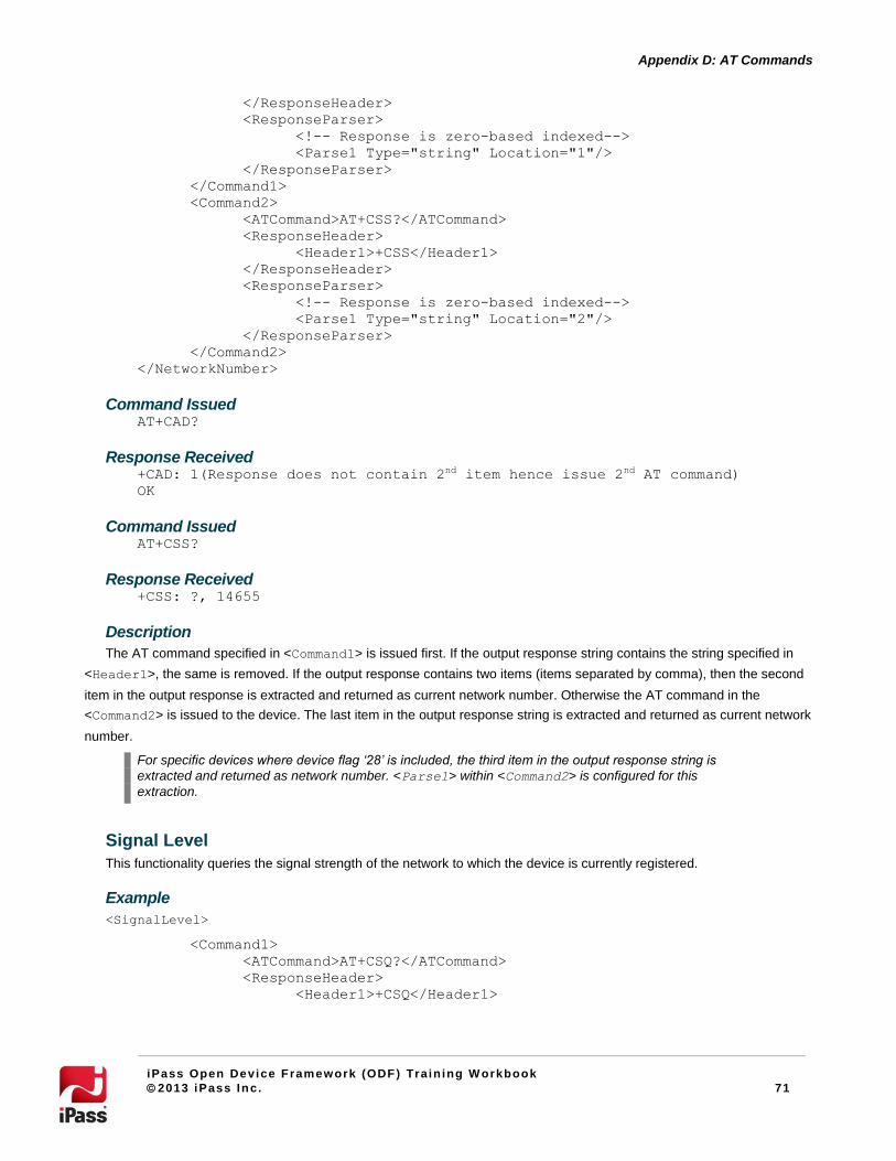
71
Appendix D: AT Commands
iPass Open Device Framework (ODF) Train ing W orkbook
2013 iPass Inc. 71
</ResponseHeader>
<ResponseParser>
<!-- Response is zero-based indexed-->
<Parse1 Type="string" Location="1"/>
</ResponseParser>
</Command1>
<Command2>
<ATCommand>AT+CSS?</ATCommand>
<ResponseHeader>
<Header1>+CSS</Header1>
</ResponseHeader>
<ResponseParser>
<!-- Response is zero-based indexed-->
<Parse1 Type="string" Location="2"/>
</ResponseParser>
</Command2>
</NetworkNumber>
Command Issued AT+CAD?
Response Received +CAD: 1(Response does not contain 2nd item hence issue 2nd AT command)
OK
Command Issued AT+CSS?
Response Received +CSS: ?, 14655
Description
The AT command specified in <Command1> is issued first. If the output response string contains the string specified in
<Header1>, the same is removed. If the output response contains two items (items separated by comma), then the second
item in the output response is extracted and returned as current network number. Otherwise the AT command in the
<Command2> is issued to the device. The last item in the output response string is extracted and returned as current network
number.
For specific devices where device flag ‘28’ is included, the third item in the output response string is
extracted and returned as network number. <Parse1> within <Command2> is configured for this
extraction.
Signal Level
This functionality queries the signal strength of the network to which the device is currently registered.
Example
<SignalLevel>
<Command1>
<ATCommand>AT+CSQ?</ATCommand>
<ResponseHeader>
<Header1>+CSQ</Header1>
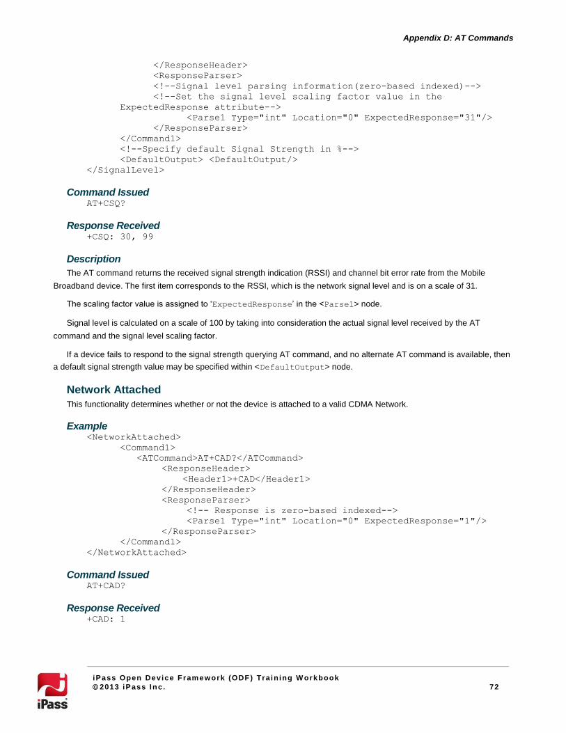
72
Appendix D: AT Commands
iPass Open Device Framework (ODF) Train ing W orkbook
2013 iPass Inc. 72
</ResponseHeader>
<ResponseParser>
<!--Signal level parsing information(zero-based indexed)-->
<!--Set the signal level scaling factor value in the
ExpectedResponse attribute-->
<Parse1 Type="int" Location="0" ExpectedResponse="31"/>
</ResponseParser>
</Command1>
<!--Specify default Signal Strength in %-->
<DefaultOutput> <DefaultOutput/>
</SignalLevel>
Command Issued AT+CSQ?
Response Received +CSQ: 30, 99
Description
The AT command returns the received signal strength indication (RSSI) and channel bit error rate from the Mobile
Broadband device. The first item corresponds to the RSSI, which is the network signal level and is on a scale of 31.
The scaling factor value is assigned to ‘ExpectedResponse’ in the <Parse1> node.
Signal level is calculated on a scale of 100 by taking into consideration the actual signal level received by the AT
command and the signal level scaling factor.
If a device fails to respond to the signal strength querying AT command, and no alternate AT command is available, then
a default signal strength value may be specified within <DefaultOutput> node.
Network Attached
This functionality determines whether or not the device is attached to a valid CDMA Network.
Example <NetworkAttached>
<Command1>
<ATCommand>AT+CAD?</ATCommand>
<ResponseHeader>
<Header1>+CAD</Header1>
</ResponseHeader>
<ResponseParser>
<!-- Response is zero-based indexed-->
<Parse1 Type="int" Location="0" ExpectedResponse="1"/>
</ResponseParser>
</Command1>
</NetworkAttached>
Command Issued AT+CAD?
Response Received +CAD: 1

73
Appendix D: AT Commands
iPass Open Device Framework (ODF) Train ing W orkbook
2013 iPass Inc. 73
Description
<Command1> is issued to determine whether or not the CDMA digital service is available. After clipping the response
header, the 0th
item (the only item) contains the required information. If the extracted item contains a value of ‘1’, it indicates
that CDMA Digital service is available for the current network. When the extracted item’s value matches the value specified
for ‘ExpectedResponse’ attribute in <Parse1> (meaning that CDMA Digital service is available), it implies that the device
is attached to the network.
Device Manufacturer
This functionality queries the device manufacturer information, similarly to the <Manufacturer> functionality specified
for GPRS devices.
Example <Manufacturer>
<Command1>
<ATCommand>AT+GMI</ATCommand>
<ResponseHeader>
<Header1>+GMI</Header1>
</ResponseHeader>
</Command1>
</Manufacturer>
<Command1> queries for the device manufacturer information.
Device Model
This functionality queries the device model, similarly to the <Model> functionality specified for GPRS devices.
Example <Model>
<Command1>
<ATCommand>AT+GMM</ATCommand>
<ResponseHeader>
<Header1>+GMM</Header1>
</ResponseHeader>
</Command1>
</Model>
<Command1> queries for the device model information.
Software Version This functionality queries the device’s software revision information, similarly to the <SwVersion> functionality specified
for GPRS devices.
Example <SwVersion>
<Command1>
<ATCommand>AT+GMR</ATCommand>
<ResponseHeader>
<Header1>+GMR</Header1>
</ResponseHeader>
</Command1>

74
Appendix D: AT Commands
iPass Open Device Framework (ODF) Train ing W orkbook
2013 iPass Inc. 74
</SwVersion>
<Command1> is queries for the software revision information.

75
Appendix E: SMS Configuration
iPass Open Device Framework (ODF) Train ing W orkbook
2013 iPass Inc. 75
Appendix E: SMS Configuration
In Open Mobile 2.2 and later clients, SMS (Simple Messaging Service) functionality is supported in ODF for GPRS
devices.
By default, Open Mobile already includes the standard AT commands to send, receive, and delete SMS messages for a
wide variety of SMS-capable devices. As a result, for SMS-enabled devices that respond to standard AT commands, no
additional configuration is required to configure SMS in ODF integration.
However, for devices that require device-specific AT commands, the configuration procedure described here will be
necessary to enable SMS functionality.
Before Configuring SMS
Before configuring SMS for a device, take a moment to determine that the target device in fact supports SMS.
Use the AT command AT+CSMS. If the response received is TRUE, then SMS is configurable for the device.
For enabling the SMS feature in ODF integration, you must configure one additional port besides the modem
port, and set that additional port as the primary port.
SMS will not be supported for ODF integrated devices if there are no additional ports (other than the modem port) which respond to AT commands. In such cases, <SMSSend> and <SMSReceive> should be set to false.
Configuration Procedure
In order to enable SMS functionality in devices that require device-specific AT commands, you will need to configure
MBliteGprs.xml. You will add an XML block to this file that corresponds to each of the device’s AT commands. In
addition, there are three SMS operations to configure for each AT command: SMS send, SMS receive, and SMS delete.
The configuration procedure is as follows:
1. Consult the device’s AT command documentation, and determine and note the specific commands required for the
device.
2. Launch your XML editor, and open MBLiteGprs.xml. In the <DeviceFunctionality> XML, create an XML
block for the Send SMS operation using the <SendSms> tag.
3. In the new <SendSms> block, create a new XML block for each separate AT command, using the tag <CommandN>,
where N is a sequential number beginning with 1 (that is, <Command1>, <Command2>, and so on). The proper XML tags
for each AT command are shown on page 76.
3. Repeat Steps 2 and 3 for the <ReadSms> and <DeleteSms> blocks.
Sample SendSms XML A complete block of XML for <SendSms>, describing three different AT commands, is shown here.
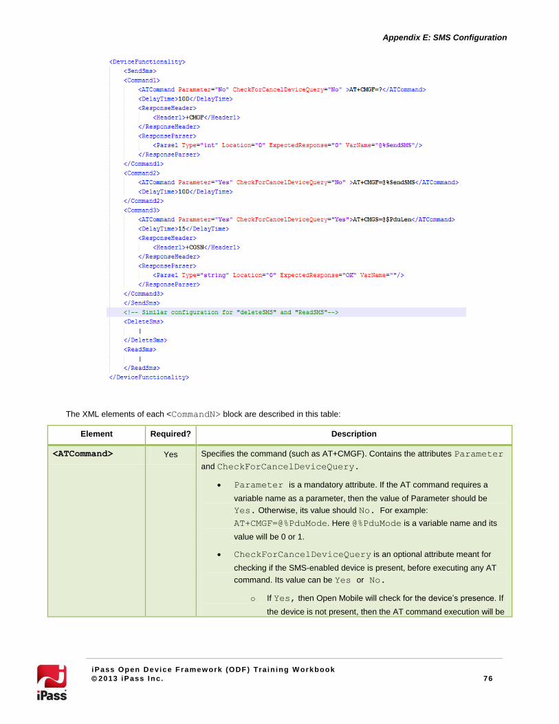
76
Appendix E: SMS Configuration
iPass Open Device Framework (ODF) Train ing W orkbook
2013 iPass Inc. 76
The XML elements of each <CommandN> block are described in this table:
Element Required? Description
<ATCommand> Yes Specifies the command (such as AT+CMGF). Contains the attributes Parameter
and CheckForCancelDeviceQuery.
Parameter is a mandatory attribute. If the AT command requires a
variable name as a parameter, then the value of Parameter should be
Yes. Otherwise, its value should No. For example:
AT+CMGF=@%PduMode. Here @%PduMode is a variable name and its
value will be 0 or 1.
CheckForCancelDeviceQuery is an optional attribute meant for
checking if the SMS-enabled device is present, before executing any AT
command. Its value can be Yes or No.
o If Yes, then Open Mobile will check for the device’s presence. If
the device is not present, then the AT command execution will be
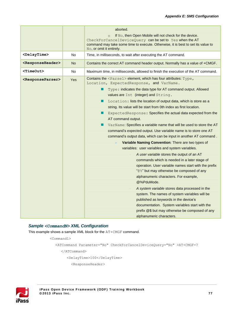
77
Appendix E: SMS Configuration
iPass Open Device Framework (ODF) Train ing W orkbook
2013 iPass Inc. 77
aborted.
o If No, then Open Mobile will not check for the device.
CheckForCancelDeviceQuery can be set to Yes when the AT
command may take some time to execute. Otherwise, it is best to set its value to
No, or omit it entirely.
<DelayTime> No Time, in milliseconds, to wait after executing the AT command.
<ResponseHeader> No Contains the correct AT command header output. Normally has a value of +CMGF.
<TimeOut> No Maximum time, in milliseconds, allowed to finish the execution of the AT command.
<ResponseParser> Yes Contains the <Parse1> element, which has four attributes: Type,
Location, ExpectedResponse, and VarName.
Type: indicates the data type for AT command output. Allowed
values are Int (integer) and String.
Location: lists the location of output data, which is store as a
string. Its value will be start from 0th index as first location.
ExpectedResponse: Specifies the actual data expected from the
AT command output.
VarName: Specifies a variable name that will be used to store the AT
command’s expected output. Use variable name is to store one AT
command’s output data, which can be input in another AT command .
Variable Naming Convention: There are two types of
variables: user variables and system variables.
A user variable stores the output of an AT
commands which is needed in a later stage of
operation. User variable names start with the prefix
“@%” but may otherwise be composed of any
alphanumeric characters. For example,
@%PduMode.
A system variable stores data processed in the
system. The names of system variables will be
published as keywords in the device’s
documentation. System variables start with the
prefix @$ but may otherwise be composed of any
alphanumeric characters.
Sample <CommandN> XML Configuration
This example shows a sample XML block for the AT+CMGF command.
<Command1>
<ATCommand Parameter="No" CheckForCancelDeviceQuery="No" >AT+CMGF=?
</ATCommand>
<DelayTime>100</DelayTime>
<ResponseHeader>

78
Appendix E: SMS Configuration
iPass Open Device Framework (ODF) Train ing W orkbook
2013 iPass Inc. 78
<Header1>+CMGF</Header1>
</ResponseHeader>
<ResponseParser>
<Parse1 Type="int" Location="0" ExpectedResponse="0"
VarName="@%SendSMS"/>
</ResponseParser>
</Command1>

79
Appendix E: SMS Configuration
iPass Open Device Framework (ODF) Train ing W orkbook
2013 iPass Inc. 79
Copyright © 2013, iPass Inc. All rights reserved.
Trademarks
iPass, iPassConnect, ExpressConnect, iPassNet, RoamServer, NetServer, iPass Mobile Office, DeviceID, EPM, iSEEL, iPass Alliance,
Open Mobile, and the iPass logo are trademarks of iPass Inc.
All other brand or product names are trademarks or registered trademarks of their respective companies.
Warranty
No part of this document may be reproduced, disclosed, electronically distributed, or used without the prior consent of the copyright holder.
Use of the software and documentation is governed by the terms and conditions of the iPass Corporate Remote Access Agreement, or
Channel Partner Reseller Agreement.
Information in this guide is subject to change without notice.
Every effort has been made to use fictional companies and locations in this manual. Any actual company names or locations are strictly
coincidental and do not constitute endorsement.