ip office · ip office 15-601085 issue 04f ... center toll fraud intervention hotline at...
TRANSCRIPT

15-601085 Issue 04f - (11 June 2009)
IP DECT Installation
IP Office

IP DECT Installation Page 215-601085 Issue 04f (11 June 2009)IP Office
© 2009 AVAYA All Rights Reserved.
NoticeWhile reasonable efforts were made to ensure that the information in this document was complete and accurate at the time ofprinting, Avaya Inc. can assume no liability for any errors. Changes and corrections to the information in this document may beincorporated in future releases.
Documentation DisclaimerAvaya Inc. is not responsible for any modifications, additions, or deletions to the original published version of thisdocumentation unless such modifications, additions, or deletions were performed by Avaya.
Link DisclaimerAvaya Inc. is not responsible for the contents or reliability of any linked Web sites referenced elsewhere within thisDocumentation, and Avaya does not necessarily endorse the products, services, or information described or offered withinthem. We cannot guarantee that these links will work all of the time and we have no control over the availability of the linkedpages.
LicenseUSE OR INSTALLATION OF THE PRODUCT INDICATES THE END USER’S ACCEPTANCE OF THE TERMS SET FORTHHEREIN AND THE GENERAL LICENSE TERMS AVAILABLE ON THE AVAYA WEBSITE AThttp://support.avaya.com/LicenseInfo/ (“GENERAL LICENSE TERMS”). IF YOU DO NOT WISH TO BE BOUND BY THESETERMS, YOU MUST RETURN THE PRODUCT(S) TO THE POINT OF PURCHASE WITHIN TEN (10) DAYS OF DELIVERYFOR A REFUND OR CREDIT.Avaya grants End User a license within the scope of the license types described below. The applicable number of licenses andunits of capacity for which the license is granted will be one (1), unless a different number of licenses or units of capacity isspecified in the Documentation or other materials available to End User. “Designated Processor” means a single stand-alonecomputing device. “Server” means a Designated Processor that hosts a software application to be accessed by multiple users.“Software” means the computer programs in object code, originally licensed by Avaya and ultimately utilized by End User,whether as stand-alone Products or pre-installed on Hardware. “Hardware” means the standard hardware Products, originallysold by Avaya and ultimately utilized by End User. License Type(s): Designated System(s) License (DS). End User may install and use each copy of the Software on only one Designated Processor, unless a different number ofDesignated Processors is indicated in the Documentation or other materials available to End User. Avaya may require theDesignated Processor(s) to be identified by type, serial number, feature key, location or other specific designation, or to beprovided by End User to Avaya through electronic means established by Avaya specifically for this purpose.Copyright Except where expressly stated otherwise, the Product is protected by copyright and other laws respecting proprietary rights.Unauthorized reproduction, transfer, and or use can be a criminal, as well as a civil, offense under the applicable law.
Third-Party Components Certain software programs or portions thereof included in the Product may contain software distributed under third partyagreements (“Third Party Components”), which may contain terms that expand or limit rights to use certain portions of theProduct (“Third Party Terms”). Information identifying Third Party Components and the Third Party Terms that apply to them isavailable on Avaya’s web site at: http://support.avaya.com/ThirdPartyLicense/
Avaya Fraud Intervention If you suspect that you are being victimized by toll fraud and you need technical assistance or support, call Technical ServiceCenter Toll Fraud Intervention Hotline at +1-800-643-2353 for the United States and Canada. Suspected securityvulnerabilities with Avaya Products should be reported to Avaya by sending mail to: [email protected]. For additional support telephone numbers, see the Avaya Support web site (http://www.avaya.com/support). Trademarks Avaya and the Avaya logo are registered trademarks of Avaya Inc. in the United States of America and other jurisdictions. Unless otherwise provided in this document, marks identified by “®,” “™” and “SM” are registered marks, trademarks andservice marks, respectively, of Avaya Inc. All other trademarks are the property of their respective owners.
Documentation information For the most current versions of documentation, go to the Avaya Support web site (http://www.avaya.com/support) or the IPOffice Knowledge Base (http://marketingtools.avaya.com/knowledgebase/).
Avaya Support Avaya provides a telephone number for you to use to report problems or to ask questions about your contact center. Thesupport telephone number is 1 800 628 2888 in the United States. For additional support telephone numbers, see the AvayaWeb site: http://www.avaya.com/support.

IP DECT Installation Page 315-601085 Issue 04f (11 June 2009)IP Office
Contents
ContentsIP DECT1.
..................................................................... 91.1 Base Stations
..................................................................... 131.2 3701 IP DECT
..................................................................... 141.3 3711 IP DECT
..................................................................... 151.4 Licensing
..................................................................... 161.5 System Capacities
..................................................................... 171.6 Technical Specification
..................................................................... 181.7 IP DECT Software
Site Survey and Planning2...................................................................... 222.1 Base Station Synchronization
..................................................................... 232.2 IP DECT System Planning
Base Station Installation3...................................................................... 303.1 TFTP Server Setup
..................................................................... 313.2 Static Base Station Configuration
..................................................................... 343.3 Using IP Office DHCP
..................................................................... 383.4 Create an IP DECT Line
..................................................................... 403.5 ADMM Setup
..................................................................... 433.6 ADMM Licensing
Handset Installation4...................................................................... 474.1 Upgrading the Phone Firmware
..................................................................... 514.2 Adding Handsets to ADMM
..................................................................... 544.3 IP Office User Creation
ADMM Web Access5...................................................................... 605.1 System Menu
............................................................................ 615.1.1 System | System Settings
............................................................................ 635.1.2 System | User Account
............................................................................ 645.1.3 System | Time Zone
............................................................................ 665.1.4 System | SNMP
............................................................................ 675.1.5 System | Backup
..................................................................... 685.2 IP Regions
..................................................................... 695.3 IP DECT Base Stations
..................................................................... 725.4 IP Trunks
..................................................................... 735.5 IP DECT Handsets
..................................................................... 755.6 System Features
............................................................................ 765.6.1 System Features | Voice Mail
............................................................................ 775.6.2 System Features | Media Server Features
............................................................................ 795.6.3 System Features | Digit Treatment
............................................................................ 805.6.4 System Features | Directory
............................................................................ 835.6.5 System Features | WML
..................................................................... 845.7 ADMM Licensing
..................................................................... 855.8 Restarting the ADMM
Maintenance6...................................................................... 886.1 Phone Maintenance
..................................................................... 906.2 DECT Monitor
..................................................................... 936.3 SMNP
..................................................................... 946.4 Syslog Output
..................................................................... 956.5 Base Station Telnet Interface
Appendix7...................................................................... 987.1 DHCP Server Operation
..................................................................... 997.2 802.1Q VLAN Support
..................................................................... 1017.3 IP Signalling and Media Stream
..................................................................... 1047.4 WML Tags
..................................................................... 1057.5 IP DECT SAP Codes
...............................................................................107Index


IP DECT Installation Page 515-601085 Issue 04f (11 June 2009)IP Office
IP DECT
Chapter 1.


IP DECT Installation Page 715-601085 Issue 04f (11 June 2009)IP Office
IP DECT:
1. IP DECTThe DECT over IP system comprises the following components:
· IP DECT Base StationsThese are connected to the LAN. Up to 32 base stations are supported for IP Office, with each able to host up to 8simultaneous calls. Different models of bases station are available for indoor and outdoor location usage, usingeither mains outlet power or Power over Ethernet (PoE). The base stations use G711, G723.1 and G729ab on theLAN side.
· Avaya DECT Mobility Manager (ADMM)One base station is used as the management interface to the IP DECT network. This base station is referred toas the ADMM. It is managed using network access from a web browser.
· LicensingThe IP DECT system is licensed through entry of a license key into the IP DECT system configuration. Thelicense controls the number of base stations supported.
· IP Office Control UnitThe IP Office, ADMM and the IP Base Stations communicate across the LAN infrastructure. The IP DECT BaseStations and the IP DECT phones communicate wirelessly.
· Voice Compression ChannelsThe control unit must be fitted with voice compression channels. A channel is required for all calls between anIP DECT phone and a non-IP device such as external trunks and non-IP phones. Calls between an IP DECTphone and other IP devices typically only require a channel during call setup. Refer to the IP Office InstallationManual for full details of fitting voice compression channels and when channels are used.
· TFTP ServerWhenever the IP DECT base stations restart, they need to upload IP DECT application software from a TFTPserver. The IP Office Manager application is not supported for this function. An IP Office control unit with anembedded voicemail memory card is only recommended for a small number (3 to 5) of base stations. For highernumbers a 3rd party TFTP server application is required.
· IP DECT PhonesA maximum of 120 IP DECT phones are supported, with up to a maximum of 100 simultaneous calls (subject toavailable base stations and IP Office voice compression channels if required).
· GAP CompatibleIn addition to supported Avaya IP DECT phones, basic call functionality is supported for GAP compatible DECTphones.

IP DECT Installation Page 815-601085 Issue 04f (11 June 2009)IP Office
Additional Components
In addition to the components above, the IP DECT system can utilize the following additional services:
· LDAP or TFTP ServerA directory of telephone numbers can be retrieved from an LDAP or TFTP server and displayed on IP DECThandsets. With IP Office, the IP Office control unit can act as the TFTP server source for its own user numbers andexternal directory numbers.
· SysLog ServerThe IP DECT base stations can output SysLog events to a SysLog server.
· SNMPThe IP DECT base stations support SNMP for system status and alarm event logging.
· SNTP ServerUsed by the IP DECT system to obtain the time and date.
Regional Support
For areas outside North America where IP DECT is available, it is supported on IP Office 3.1 and higher. For NorthAmerica, IP DECT is supported on IP Office 4.0 May 2007 maintenance release and higher. Note however that IP DECTBase stations and phones for different regions are not compatible. Additionally the optional directional beam aerials forthe RFP34 base station are not supported in North America.

IP DECT Installation Page 915-601085 Issue 04f (11 June 2009)IP Office
IP DECT:
1.1 Base StationsWhen used with IP Office, the IP DECT supports up to 32 base stations. One base station is designated during installationas the Avaya DECT Mobility Manager (ADMM) and is used to configure and control the IP DECT system. Note that a basestation is also called a Radio Fixed Part or RFP.
The following types of base station are supported for use with IP Office:
· RFP31: Indoor Base StationNo longer available and not supported in North America. This base station is for indoor use only. It has integralaerials and can be powered by either a mains adapter or by 802.3af Power over Ethernet supply.
· RFP32: Indoor Base StationThis base station is for indoor use only. It has integral aerials and can be powered by either a mains adapter or by802.3af Power over Ethernet supply. For Australia and New Zealand the mains adaptor is not currently supported.
· RFP33: Outdoor Base StationNo longer available and not supported in North America. This base station can be used outdoors or indoors. Theoutdoor IP Base Station can only be powered by 802.3af Power over Ethernet.
· RFP34: Outdoor Base StationThis base station can be used outdoors or indoors. The outdoor IP Base Station can only be powered by 802.3afPower over Ethernet.
Base Station Type RFP31 RFP32 RFP33 RFP34
North America
Rest of World
Indoor
Outdoor
Mains Power OutletAdaptor
Power over Ethernet
Internal Aerials
External Aerials
TNC Aerial Connectors
Encryption
Each base station can handle simultaneous calls for up to 8 DECT phones at any time. Additional phones will connect tothe next nearest base station with sufficient signal strength if it has available capacity.
Groups of IP Base Station are called clusters. Within a Cluster, IP Base Stations are synchronized to enable a seamlesshand over when a user crosses from one IP Base Station’s zone of coverage to another. For synchronization, it is notnecessary for an IP Base Station to communicate directly with all other IP Base Stations in the system. Each IP BaseStation only needs to be able to communicate with the next IP Base Station in the chain. It is preferable for an IP BaseStation to see more than one IP Base Station to guarantee synchronization in the event that one of the IP Base Stationsfails.
Power over Ethernet Support
All the base stations can be used with Power over Ethernet (PoE). They are classified as Class 0 devices. Note that theAvaya 1151 MidSpan Power Unit should not be used to provide power.

IP DECT Installation Page 1015-601085 Issue 04f (11 June 2009)IP Office
Aerials
By default all the base stations are supplied with omni-directional aerials. For the RFP31 and RFP32 base stations theaerials are integral and cannot be changed. For the RFP33 and RF34, the aerials are connected by TNC connectors andcan be replaced with beam or dipole aerials. The use of beam aerials is not supported in North America. The use of third-party aerials is not supported by Avaya.
RFP31
This base station is for indoor use only. It has integral omni-directional aerials and can be powered by either a mainsadapter or by 802.3af Power over Ethernet supply. The RFP31 has a single multi-colour LED that shows the differentstates during startup and operation.
This type of base station is no longer available from Avaya and is not supported in North America.

IP DECT Installation Page 1115-601085 Issue 04f (11 June 2009)IP Office
IP DECT: Base Stations
RFP32
This base station is for indoor use only. It has integral omni-directional aerials and can be powered by either a mainsadapter or by 802.3af Power over Ethernet supply. The RFP32 has 3 separate LEDs in red, orange and green showing thedifferent states during startup and operation.
RFP33
This base station can be used indoors and outdoors. It has two external omni-directional aerials. The base station canonly be powered using an 802.3af Power over Ethernet supply. Connection requires the base station to be opened andthe LAN cable to be connected to an internal IDC punch down connector block.
This type of base station is no longer available from Avaya and is not supported in North America.
RFP34
This base station can be used indoors and outdoors. It has two external omni-directional aerials. The base station canonly be powered using an 802.3af Power over Ethernet supply. Connection requires the base station to be opened andthe LAN cable to be connected to an internal RJ45 or IDC punch down connector block.

IP DECT Installation Page 1215-601085 Issue 04f (11 June 2009)IP Office
The following technical specification is applicable to the currently available IP DECT base stations.
Dimension RFP32 RFP34
Aerials 2 Internal. 2 External. TNC connectors.
Power over Ethernet Class 0. Class 0.
Ambient Temperature -5°C to +45°C/23°F to 113°F. -25°C to +55°C/-13°F to 131°F.
Relative Humidity 5 to 95% non-condensing. 5 to 95% non-condensing.
Current Consumption 120mA. 120mA.
Power 6W. 6W.
Type of Ingress Protection IP20. IP55.
Flame Resistance UL94 V0-5VB. UL94 V0.
Mounting Wall. Wall or mast.
Color Ice grey. Light grey.
Weight * 417g/15 ounces. 970g/ 34 ounces.
Width * 151mm/6 inches. 240mm/9.5 inches.
Height * 101mm/4 inches. 260mm/10.25 inches.
Depth * 32mm/1.26 inches. 60mm/2.4 inches.
*Dimensions exclude aerials (if external) and power supply adaptor is used.

IP DECT Installation Page 1315-601085 Issue 04f (11 June 2009)IP Office
IP DECT: Base Stations
1.2 3701 IP DECTThis IP DECT phone is not supported in North America.
· Listen-only hands free speaker.
· SOS Emergency key for speed dialing an emergency number.
· Information key that can be used for:
· Phone number lists and voice mail indication.
· Information and speaker key flash when active.
· 50 phone book entries in every handset
· 10 possible ring tones with temporary mute.
· 4-level signal strength display.
· Speaker and handset volume, 3-levels and mute capability.
· Manual and automatic key lock (1 minute timer).
· Temporary ring tone muting.
· Silent charging.
· 12 menu languages: Czech, Danish, Dutch, English, Finnish, French, German, Italian, Norwegian, Portuguese,Spanish and Swedish. However, in the Czech and Norwegian language mode some menu items may appear in theEnglish language.
· Illuminated 3-line graphic display (96 x 33 pixels), variable 3-level contrast.
· Stand-by time: up to 100 hours.
· Talk time: up to 10 hours.
· Charge time: max. 6 hours for empty batteries.
· Weight: 138 grammes / 5 ounces including 3 AAA (NiMH) batteries.
· Dimensions (Height x Width X Depth): 146 x 55 x 28 mm / 5.7' x 2.1' x 1.1'.
Optional telephone accessories include:
· Desktop charger.
· An adapter cord for use with headsets.
· Heavy-duty belt clip.

IP DECT Installation Page 1415-601085 Issue 04f (11 June 2009)IP Office
1.3 3711 IP DECT
The 3711 phone supports the same features as the 3701 IP DECT handset but with the following differences:
· Full hands-free speakerphone operation.
· Headset connection (2.5 mm jack).
· Vibrating alarm.
· Personal phone book with 100 entries
· Access to system phone book.
· Voice Mail indication.
· Choice from 30 ring tones.
· Speaker and handset volume, 7-levels and mute capability.
· Automatic call pick-up using a headset.
· 10 menu languages: Danish, Dutch, English, Finnish, French, German, Italian, Portuguese, Spanish and Swedish.
· Illuminated 5-line graphic display, (96 x 60 pixels), variable 7-level contrast.
Optional handset accessories include:
· Desktop charger.
· An adapter cord for use with headsets.
· Heavy-duty belt clip.

IP DECT Installation Page 1515-601085 Issue 04f (11 June 2009)IP Office
IP DECT: 3711 IP DECT
1.4 LicensingThe IP DECT solution requires a license entered into the main base station's (ADMM) configuration in order to operate.This license is based on a number of factors:
· A transaction ID supplied when ordering the IP DECT system.
· A serial number generated from the MAC addresses of some of the base systems within the IP DECT system.
· The number of base station MAC addresses used for this varies with the total number of base stations neededwith the system.
· The base stations used for licensing must remain in the system. If any one should fail or be temporarilyremove, the capacity of the system may be reduced.
The following table summarizes the number of base stations licensed and the number required to validate the license.
Number of BaseStations Licensed
Number of MAC AddressesRequired for Licensing
Minimum Number of LicensedBase Stations to Remain
Operational
1 1 1
2 2 1
3 to 5 3 2
6 to 32 3 2
Plug and Play LicensingFor IP DECT firmware 1.1.9 and higher, a simplified method of licensing is supported using pre-licensed RFP32 and RFP34base station kits. These kits allow easier installation and upgrades by removing the need to separately obtain andlicenses based on the MAC addresses of selected base stations.
For initial installation, a pre-licensed and ready to go two RFP32 base-station kit is available. Additionally pre-licensedbase station upgrade kits (RFP32 and RFP34) are available that can be added to the system. When up to 8 plug and playbase stations are present, the number of bases station supported in total is up to 32).
Both license mechanisms (manually obtained licenses based on base station MAC addresses and 'plug and play') can bemixed.

IP DECT Installation Page 1615-601085 Issue 04f (11 June 2009)IP Office
1.5 System CapacitiesThe maximum number of simultaneous calls is limited by the number of VCM channels of the IP Office and the channelsof the IP Base Stations. The maximum number of simultaneous calls can also be affected by the direct mediaconfiguration in the IP Office Manager.
Base Stations
The IP DECT base stations have the following capacity.
· Up to a maximum of 32 base stations are supported.
· 1 base station must be set as the ADMM. This does not affect the base stations call handling. However this basestation must remain in the system at all time for the IP DECT system to be operational.
· Each base station can support up to 8 simultaneous calls to/from DECT phones.
· Additional calls are only possible if another base station with free capacity and with appropriate signal strength iswithin range.
IP DECT Phones
The IP DECT system supports the following phone capacity when used with IP Office:
· Up to 120 IP DECT phones are supported.
· Up to 100 IP DECT phones can be active simultaneously.
· It is recommended that no more than 50 handsets are active simultaneously if the ADMM base station is also beingused for DECT wireless call connection. If necessary the DECT functions of the ADMM base station can be disabled.
· As detailed above, a maximum of 8 DECT phones can be connected via any single base station at any time.
· The IP DECT system supports GAP compatible DECT handsets. However only basic functions to make and answercalls are supported on these devices.

IP DECT Installation Page 1715-601085 Issue 04f (11 June 2009)IP Office
IP DECT: System Capacities
1.6 Technical Specification
Digital Enhanced Cordless Telecommunication (DECT)
The standard (ETS 300 175) essentially specifies the air interface, known as the radio interface. Voice and data can bothbe transmitted via this interface.
DECT technical characteristics are:
· United States:
· Frequency Range: 1.920 to 1.930 GHz (10MHz bandwidth).
· Carrier Frequencies: 5 (1.728 MHz spacing) with 12 time slots each.
· Transmit Power: 20dBm.
· Maximum transmission power of 4 mW (100 mW peak).
· Europe, Middle East and Asia:
· Frequency Range: 1.880 to 1.900GHz (20MHz bandwidth).
· Carrier Frequencies: 10 (1.728 MHz spacing) with 12 time slots each.
· Transmit Power: 24dBm.
· Maximum transmission power of 10 mW (250 mW peak).
· Doubling the number of time slots using the TDMA process
· Net data rate per channel of 32 kbps for voice transmission using ADPCM.
· Voice coding using the ADPCM method.
Generic Access Profile (GAP)
· The GAP standard (ETS 300 444) is based on the same technology as DECT, but is limited to the most importantbasic features. This standard was created in order to allow phones of different vendors to be used on any type ofDECT system. It thus represents the smallest common denominator of all manufacturer-specific variants of theDECT standard.
· An important limitation in the GAP standard is that external handover is not possible. For this reason connectionhandover is used, which is supported by GAP terminals.
· The operation of GAP-capable phones is comparable to that of analogue terminals. For example, features can becalled up via * and # procedures.

IP DECT Installation Page 1815-601085 Issue 04f (11 June 2009)IP Office
1.7 IP DECT SoftwareThe software for installation of an IP DECT system with IP Office is included on the IP Office Administrator Application CD.The files are located in the folder IPDECT.
The files are as follows (note that the actual file names include version labels which may vary):
File Description
ADM_Configurator.jar This is a configuration tool for the static IP address setup of base stations. It requiresthe PC to have JVM 1.1.4 (Java Virtual Machine) installed. The simplest way to meetthat requirement is to run the configurator on a PC that has had the IP Office SystemStatus Application (SSA) installed.
ADMM_RFP.tftp This is the software file that needs to be uploaded by TFTP to each base stationwhenever it restarts.
DECTNetmonitor.exe This tool can be used to monitor the IP DECT system.
up_avaya_3701.exe This tool is used to upgrade 3701 phones.
up_avaya_3711.exe This tool is used to upgrade 3711 phones.

IP DECT Installation Page 1915-601085 Issue 04f (11 June 2009)IP Office
Site Survey and Planning
Chapter 2.

IP DECT Installation Page 2015-601085 Issue 04f (11 June 2009)IP Office
2. Site Survey and PlanningCoverage In Theory
Given ideal open field conditions, the range between a handset and base station can be up to 600 metres (approximately2000 feet). However where obstacles absorb signal strength and reflected signals giving increased error rates, the rangeis more realistically between 30 metres (98 feet) indoors and 300 metres (984 feet) outdoors.
Coverage In Practice
In practice, no rules or guarantees can be given for base station coverage. Coverage is affected by too many factors thatare unique to each site. The following is a guide to those factors that can affect coverage and should be consideredduring any site survey.
· Obvious causes of signals problems:
· Metal surfaces.
· Concrete thickness greater than 1 metre (3 feet).
· Also beware of:
· Windows with Reflective Film or Specialized Glass. These produce increased signal reflection and reduced signal pass-through.
· Wire Meshes and Grills with Apertures of Less than 4cm (1.5 inches). These block signals as effectively as continuous metal sheet.
· Fire Doors These block the signals. In multi-occupancy building such as hotels the high number of fire-doors may be aproblem.
· Stair Wells In modern office buildings, stair wells frequently combine concrete building supports, fire doors and theintervening floor material, making them a special problem.
· Screened Rooms Typically found in offices involved with TV, video and radio production, but also possible in computer centers.
· Empty Sites Do not perform a survey on a site that is not yet occupied. The survey results will differ from those of thesame site once occupied by the customer business.
· Be Aware of:
· Signal Direction The signal from a base station does not propagate evenly in all directions. The signal typically propagatesstrongest in the horizontal plane. However the ability for a base station to serve callers located on floorsabove or below it should not be ignored. This may allow coverage to be extended to areas not frequently usedand so not meriting a dedicated local base station.
· By default all the base stations are omni-directional. For the RFP33 and RF34, the aerials are connectedby TNC connectors and can be replaced with beam or dipole aerials. The use of beam aerials is notsupported in North America. The use of third-party aerials is not supported by Avaya.
· Radio Signals The ability to receive normal broadcast radio signals in an area is not an indication that DECT signalling will bereceived.

IP DECT Installation Page 2115-601085 Issue 04f (11 June 2009)IP Office
Site Survey and Planning:
Performing a Site Survey
We cannot give precise recommendations for a site survey as every site will vary. However a site survey is a prerequisiteto installation in all cases. The correct and effective placement of base stations will prevent problems and maximizecoverage.
Site survey kits are available from Avaya. These contain a specially adapted base station that is able to operateindependently. The kit also includes handsets and necessary chargers.
· While performing a survey you will require the following information:
· Building Layout Accurate building plans are an essential aid to both the site survey and also for later fault analysis. Ensurethat you have an accurate plan of the customer premises, including the locations of mains power outlets andnetwork connection points.
· The area of coverage required? Which areas within the plans the customer expects to be covered. Do they expect coverage outside thebuilding and or in buildings separate from the main building.
· The number of simultaneous users within different areas? Each base station can support up to 8 simultaneous calls.
· Perform the survey during normal business hours. The movement of large items of machinery such as lifts willthen be observable during the survey.
· Ensure that you have read this documentation and understand the importance of base station clusters and theneed for wireless synchronization between base stations within a cluster, including the need for redundancy.
· As the survey takes place, note whether additional network connection points will be required and or mains poweroutlets. Consider the use of Power over Ethernet, if possible in order to simplify base station installation.
· As a general objective, the signal strength from one base station location to another should not drop below -70dBm.
Using DECT Handsets for a Site Survey
This function puts the phone in the 'site survey mode'. While in this mode the phone can also receive a call to allowaudible checking of the call quality as you move around the survey area. .
1. Press Menu.
2. Enter R***76#.
3. Select Site Survey.
4. Press OK.
5. Press Esc.
6. The phone displays the IP Base Stations and the actual field strength of the receiving signal in dBM.
· RFPIThis line shows the PARK number of the IP DECT system to which the phone is connected.
· FEThis line shows the frame errors detected by the portable part (PP = the phone) and the fixed part (FP = thebase station to which it is connected). Occasional framing errors are acceptable.
· -dBM and RPNThese two lines show the signal strength (-dBm) and the Base Station ID (RPN) of the base station providingeach signal. The Base Station ID's match those shown on the IP DECT Base Station screen when accessing theADMM web configuration. Note that the signal strength is in negative numbers, for example 70 is a weakersignal than 50.
7. To leave site survey mode, switch the phone off and on again.

IP DECT Installation Page 2215-601085 Issue 04f (11 June 2009)IP Office
2.1 Base Station SynchronizationTo allow call handover when a caller moves from the coverage area of one base station to another, the base stationsneed to exchange synchronization signals. They do this using wireless signalling between the base stations. This thereforerequires the base station coverage areas to overlap.
For one IP base station to synchronize to another IP Base Station, the signal strength cannot drop below –70 dBm. Youmust consider this requirement during the site survey.
Within the IP DECT configuration, all base stations in the same physical area with overlapping coverage are configuredwith the same 'cluster' number. During system start-up, these base stations exchange synchronization signals with othersin the same cluster until all base stations are synchronized.
If a base station loses the synchronization signal it will not accept new calls until it is able to synchronize again. If theunsynchronized base station already has active calls, it will delay up to a maximum of 3 minutes before it tries tosynchronize again.
An IP DECT installation is more reliable if each base station can receive the synchronization signals from more than oneother base station in the same cluster. Clusters without multiple synchronization paths can cause problems if a singlebase station loses the synchronization signal from its neighbour or needs to be switched off or restarted duringmaintenance.
Unreliable Installation
With this layout, the loss of synchronizationsignal causes the loss of the base station.None of the base stations have backupredundant signalling to other base stations.Potentially this may cause loss ofsynchronization within the whole cluster.
Reliable Installation
With this layout, each base station hasmultiple synchronization signal paths toother base stations in the cluster. Theinterruption of any signal path does notcause loss of synchronization within thecluster.
Sometimes IP Base Stations do not or cannot be synchronized, for example if they are in different buildings. These basestations should be configured into separate clusters. This is reasonable so long as users are aware that handover of callswill not be possible when they move between areas covered by different clusters.

IP DECT Installation Page 2315-601085 Issue 04f (11 June 2009)IP Office
Site Survey and Planning: Base Station Synchronization
2.2 IP DECT System Planning
Customer Details
Information Details
Site Details
– Address
– Business Hours
– General Telephone Number
Customer
– Name
– Telephone Number
Network Administrator
– Name
– Telephone Number
Survey Date
– Survey Contact
– Installation Date
– Installation Contact

IP DECT Installation Page 2415-601085 Issue 04f (11 June 2009)IP Office
System Details
Information Details Note
System Name
TAN
PARK ID Obtained during installation.
Serial Number Obtained during installation.
License Key Obtained during installation.
TFTP Server IP Address
IP Address Method ¨ Station/ ¨ IP Office DHCP/ ¨ DHCP
IP Office LAN Address
DNS Server IP Address
Domain Name
NTP Server IP Address
Syslog Server IP Address Optional
Syslog Port Optional
VLAN ID Optional

IP DECT Installation Page 2515-601085 Issue 04f (11 June 2009)IP Office
Site Survey and Planning: IP DECT System Planning
Base Stations
Obtain a building plan to use for the site survey and record the locations of the base stations on that plan. Base stationnot using PoE will require a power supply unit and access to a mains power outlet within 1 metre (3 feet) of the basestation.
ID MAC Address IP Address Type Location
Cluster PoE ADMM License
00 : : : : : 31/32/33/34 Yes/No ¨ ¨
01 : : : : : 31/32/33/34 Yes/No – ¨
02 : : : : : 31/32/33/34 Yes/No – ¨
03 : : : : : 31/32/33/34 Yes/No – –
04 : : : : : 31/32/33/34 Yes/No – –
05 : : : : : 31/32/33/34 Yes/No – –
06 : : : : : 31/32/33/34 Yes/No – –
07 : : : : : 31/32/33/34 Yes/No – –
08 : : : : : 31/32/33/34 Yes/No – –
09 : : : : : 31/32/33/34 Yes/No – –
10 : : : : : 31/32/33/34 Yes/No – –
11 : : : : : 31/32/33/34 Yes/No – –
12 : : : : : 31/32/33/34 Yes/No – –
13 : : : : : 31/32/33/34 Yes/No – –
14 : : : : : 31/32/33/34 Yes/No – –
15 : : : : : 31/32/33/34 Yes/No – –
16 : : : : : 31/32/33/34 Yes/No – –
17 : : : : : 31/32/33/34 Yes/No – –
18 : : : : : 31/32/33/34 Yes/No – –
19 : : : : : 31/32/33/34 Yes/No – –
20 : : : : : 31/32/33/34 Yes/No – –
21 : : : : : 31/32/33/34 Yes/No – –
22 : : : : : 31/32/33/34 Yes/No – –
23 : : : : : 31/32/33/34 Yes/No – –
24 : : : : : 31/32/33/34 Yes/No – –
25 : : : : : 31/32/33/34 Yes/No – –
26 : : : : : 31/32/33/34 Yes/No – –
27 : : : : : 31/32/33/34 Yes/No – –
28 : : : : : 31/32/33/34 Yes/No – –
29 : : : : : 31/32/33/34 Yes/No – –
30 : : : : : 31/32/33/34 Yes/No – –
31 : : : : : 31/32/33/34 Yes/No – –

IP DECT Installation Page 2615-601085 Issue 04f (11 June 2009)IP Office
Handsets
The number must be unique and within the requirements and restrictions of the IP Office system. Refer to the IP OfficeManager documentation.
Number Name Type IPEI

IP DECT Installation Page 2715-601085 Issue 04f (11 June 2009)IP Office
Base Station Installation
Chapter 3.

IP DECT Installation Page 2815-601085 Issue 04f (11 June 2009)IP Office
3. Base Station InstallationThis section does not cover the physical installation of the base stations, ie. wall mounting and connection of powersupplies. That should be done in accordance with the information provided with the base stations. This section covers thesoftware configuration of the base stations.
Installation Stages
· TFTP Server SetupRequired to provide software to the IP DECT base stations.
· Base Station IP Address ConfigurationThe basic settings of IP address and location of the TFTP server are input into the base stations using one of thefollowing methods.
· Static IP Addressing
· Dynamic (DHCP) IP Addressing using IP Office
· Dynamic (DHCP) IP Addressing using a 3rd Party DHCP Server
· IP DECT Line CreationAn IP DECT line is required in the IP Office configuration. If the IP Office is providing DHCP support for the basestation, this will have been setup as part of the DHCP configuration above.
· ADMM ConfigurationBasic configuration of the IP DECT system is required in order for the base stations to connect to each other.
· ADMM LicensingOnce basic ADMM configuration has been completed and all the base stations are connected, the system licensecan be obtained and entered.
Prerequisites
· ¨ Site SurveyA site survey must be performed. This may be done as part of the installation or prior to installation. Regardless asite survey is necessary as most DECT problems will center on base station coverage.
· ¨ Product KnowledgeEnsure that you have read this documentation fully before starting installation.
· ¨ Handset ChargingHandset installation, though performed after base station installation, requires the handset to be charged.Therefore while base station installation is being performed, ensure that the IP DECT phones are placed into theircharging cradles and are charging.
Information Required
1.¨ TAN (Transaction ID Number)This number is provided with the IP DECT system when ordered.
2.¨ Base Station MAC AddressesMAC Addresses of the base stations selected for license validation.
3.¨ Licensing Site URLhttp://licence.aastra-detewe.de/Avaya.
4.¨ IP Office DetailsThe IP address of the LAN connection to the IP Office.
5.¨ IP Office LoginService user name and password with Administrator or Manager security group rights for the IP Office. Thoserights are required in order to create new extensions.
6.¨ ADMM DetailsThe IP address and MAC address of the base station acting as the ADMM.
7.¨ Base Station MAC Addresses
8.This is printed on a label on each base station.
9.¨ Base Station Clusters
10.¨ Base Station IP Address DetailsAs follows:
· ¨ IP Address for each base station (Mandatory).
· ¨ Subnet Mask (Mandatory).

IP DECT Installation Page 2915-601085 Issue 04f (11 June 2009)IP Office
Base Station Installation:
· ¨ TFTP Server IP Address (Mandatory).
· ¨ TFTP File Name (Mandatory).
· ¨ ADMM Base Station IP Address (Mandatory).
· ¨ Default Gateway IP Address (Optional).
· ¨ DNS Address (Optional).
· ¨ DNS Domain (Optional).
· ¨ Broadcast Address (Optional).
· ¨ NTP Server Address (Optional).
· ¨ Syslog IP Address (Optional).
· ¨ Syslog Port (Optional).
· ¨ VLAN ID (Optional).
Tools Required
· ¨ IP Office ManagerPC with IP Office Manager.
· ¨ Web Browser The browser used for service access has to be at least Microsoft Internet Explorer 6.0 or Mozilla Firefox 1.0 andmust have frame support, javascript and cookies enabled. If either javascript is missing, or cookies are notallowed, a warning message will be displayed.
· ¨ Internet Web Access

IP DECT Installation Page 3015-601085 Issue 04f (11 June 2009)IP Office
3.1 TFTP Server SetupFollows a base station restart or loss of power, each base station retains only its IP address settings (if it has beenstatically configured). If not statically configured the base station needs to obtain its IP address settings via DHCP.
In either case the base stations then need to upload from a TFTP server the IP DECT base station software before theybecome operational again. Therefore there is a requirement for the IP DECT system to have permanent access to a TFTPserver.
· While the IP Office Manager application can act as a TFTP server it is not recommended for scenarios such as thiswhere it needs to be left running permanently.
· IP Office control units fitted with Embedded Voicemail memory cards can also act as TFTP servers. However due tothe boot time this is only supported for 3 base stations connected to a Small Office Edition or 5 base stationsconnected to an IP406 V2 or IP Office 500 control unit.
· If no existing TFTP server is available, TFTP server software can be downloaded from the Avaya support web siteat http://support.avaya.com.
TFTP Server Setup
1.Check that the PC chosen to run the TFTP server has a fixed IP address.
2.Install and configure the TFTP software as per the software manufacturers instructions.
3.From the IPDECT folder on the IP Office Administrator Applications CD or DVD, copy the file ADMM_RFP_1_1_5.tftp (version number may vary) to the root directory configured for the TFTP server. If using the Avaya providedTFTP server software:
· Select System | Setup and select the Outbound tab.
· Set the Outbound file path to the folder location where you placed the software file.
4.From another PC on the LAN test operation of the TFTP server.
· Select Start and then Run.
· Enter cmd.
· In the command line window enter tftp -i 192.168.42.203 get ADMM_RFP_1_1_5.tftp, substituting the IPaddress of the TFTP server and the file name that matches the .tftp file placed on the TFTP server.
· The response should be Transfer successful. Note: Transfer will fail with can't write to local file if thetransfer file is already present in the folder part from which the command is being executed.
5.Proceed to base station installation.
· If using static IP address installation see Static Base Station Configuration .
· If using dynamic IP address installation see Dynamic Base Station Configuration .
31
34

IP DECT Installation Page 3115-601085 Issue 04f (11 June 2009)IP Office
Base Station Installation: TFTP Server Setup
3.2 Static Base Station ConfigurationThis stage covers configuring the IP address settings of the base stations. This is best done before the base stations aremounted in position.
· This process uses static IP address setup. If DHCP address setup is required see Dynamic Base StationConfiguration .
Prerequisites
· The TFTP Server must be running and tested. See TFTP Server Setup .
Information Required
· ¨ Base station MAC addressThis is printed on a label on each base station.
· ¨ Base Station IP Address DetailsAs follows:
· ¨ IP Address for each base station (Mandatory).
· ¨ Subnet Mask (Mandatory).
· ¨ TFTP Server IP Address (Mandatory).
· ¨ TFTP File Name (Mandatory).
· ¨ ADMM Base Station IP Address (Mandatory).
· ¨ Default Gateway IP Address (Optional).
· ¨ DNS Address (Optional).
· ¨ DNS Domain (Optional).
· ¨ Broadcast Address (Optional).
· ¨ NTP Server Address (Optional).
· ¨ Syslog IP Address (Optional).
· ¨ Syslog Port (Optional).
· ¨ VLAN ID (Optional).
Tools Required
· ¨ IP Office System Status ApplicationPC with IP Office Manager and IP Office System Status Application (SSA) Installed. Installation of this applicationalso installs the necessary Java components to use the ADMM Configurator tool.
· ¨ IP Office Administrator Application CD or DVDThe software tool required is the ADM_Configurator.jar file located in the IPDECT folder. This tools needs JavaRuntime Environment version 1.4 or higher installed on the PC. That can be achieved by installing the IP OfficeSystem Status Application (SSA).
34
30

IP DECT Installation Page 3215-601085 Issue 04f (11 June 2009)IP Office
Process
1.For this process the PC, the base station and TFTP server should all be connected to the same LAN.
2.If the TFTP server provides any view of file requests and transfers, it will be useful to have that view visible duringthis process.
3.Apply power to the base station.
4.Locate the IP DECT folder on the IP Office Administrator Applications CD or DVD.
5.Double-click on the ADM_Configurator_1_1_5.jar file (the version number may vary).
6.This tools needs Java Runtime Environment version 1.4 or higher installed on the PC. That can be achieved byinstalling the IP Office System Status Application (SSA).
7.In the MAC Address field enter the MAC address of the base station.
8.Click List configuration.
9.If the base station has never been statically configured, no settings are shown but the message list ok at thebottom-left confirms that communication occurred.
10.If the base station has previously been statically configured, the previous settings should be displayed.
11.Check that Use local configuration is set to yes. This set the base station to use static addressing rather thanDHCP. To return the base station to DHCP operation, this setting must be changed back to no.
12.Enter the parameters required.
13.The parameters shown above are mandatory.
14.Parameters not shown can be added by clicking Add parameter, selecting the required parameter from the NewParameter list and then clicking Add.
15.The base station assigned the same IP Address as entered for the ADMM IP Address becomes the ADMM basestation. Any base station can be used for this function, however there must only be one ADMM base station.

IP DECT Installation Page 3315-601085 Issue 04f (11 June 2009)IP Office
Base Station Installation: Static Base Station Configuration
16.Click Send Configuration. The response at the bottom left should be send ok. Click Reset Configuration andthen List Configuration to confirm the settings sent to the base station.
17.If the settings are correct, the base station will request the base station software file from the TFTP server.Depending on how long this static configuration has taken, it may be necessary to remove and then reapply powerto the base station in order to trigger the download.
18.Make a note of the base stations MAC address, the IP address assigned to it and which one of the base station IPaddresses was used for the ADMM base station.
19.Repeat this process for any other base stations, ensuring that only one base station is given the same IP addressas the ADMM IP Address.
20.Proceed to Create an IP DECT Line .
38

IP DECT Installation Page 3415-601085 Issue 04f (11 June 2009)IP Office
3.3 Using IP Office DHCPThe IP DECT base stations can be installed using DHCP if a DHCP server is available. This can include using the IP Officeas the DHCP server if no other DHCP is present on the network. The process below covers use of the IP Office. If a 3rdparty DHCP server is to be used, refer to the DHCP Server Operation notes in the appendix.
Prerequisites
· The TFTP Server must be running and tested. See 2. TFTP Server Setup .
Warning
· Adding a line requires the IP Office to be rebooted. That will end any current calls and services on the IP Office.
Information Required
· ¨ IP Office LoginService user name and password with Administrator or Manager security group rights for the IP Office. Thoserights are required in order to create new extensions.
· ¨ ADMM DetailsThe IP address and MAC address of the base station that will act as the ADMM.
· ¨ Base Station DetailsThe MAC addresses of the IP DECT base stations.
Tool Required
· ¨ IP Office ManagerPC with IP Office Manager.
98
30

IP DECT Installation Page 3515-601085 Issue 04f (11 June 2009)IP Office
Base Station Installation: Using IP Office DHCP
DHCP Using IP Office
1.Note that this process require the IP Office to reboot and so will end all currently connected calls and services.
2.Start IP Office Manager and click to receive the configuration from the IP Office system.
3.In the left hand pane select System.
4.On the System tab, ensure that the TFTP Server IP Address is set correctly. Click OK.
· Select either the LAN1 or LAN2 tab, depending on which LAN the IP DECT base stations are to be connected.
· Select the LAN Settings sub-tab.
· The DHCP Mode should be set to Server.
· Set the Number of DHCP IP Addresses as required. The range should be sufficient to allow for all devicesthat will be using DHCP. The dynamic addresses are issued from the IP Address set for the LAN upwards.
· Click OK.
5.Right-click on Line. Select New and then IP DECT Line.
6.The IP DECT Line option is greyed out if the configuration already contains an IP DECT line.
7.An existing IP DECT line is shown with a icon and the Line Type of IP DECT.
8.The Line tab is for information only. All the fields are greyed out and cannot be altered. The information shown onthis tab is described below.
· Line NumberAuto-populated on IP DECT line creation, starting at 240.
· Number Of Channels, Outgoing Channels and Voice Channels -Will change to indicate the number of IP DECT extensions associated with the IP DECT Line.
· Incoming and Outgoing Group ID Auto-populated on IP DECT line creation, starting at 240. This value should NOT be used for outgoing callrouting as trunks calls to an IP DECT line will not be successful.
· ExtensionsShows the DECT extensions created within the IP Office configuration.

IP DECT Installation Page 3615-601085 Issue 04f (11 June 2009)IP Office
9.Click on the Gateway tab.
· In the Gateway IP Address field, enter the IP address that the DHCP server should reserve for the basestation that will act as the ADMM. Ensure that this address is within the range of dynamic addresses the IPOffice can assign.
· The remaining fields should only be changed from their defaults if required. Their functions are describedbelow:
· Compression ModeSelect the compression mode from the drop down list.
· GainThis field allows the audio signal strength for calls between the IP Office and IP DECT extension to beadjusted.
· Silence SuppressionWhen selected, H.323 terminals will not send data if they are silent, this is useful when optimizing datatraffic.
· Allow Direct Media Path When disabled, the media (voice) path always passes through the IP Office Unit. When enabled, theremote end may be told of a new IP address for the media path if, for example, the call is transferred toa H.323 extension. Enabling this option may cause some vendors problems with changing the media pathmid call.
· Auto-Create ExtensionIf enabled, when an IP DECT handset is subscribed to the ADMM, extension and user entries areautomatically created in the IP Office configuration.
· Select Enable DHCP Support.
· In the Boot File field enter the name of the .tftp file copies from the IP DECT folder on the IP OfficeAdministrator Application CD to the TFTP server. The TFTP server IP address is taken from that set on theIP Office's System | System tab. Up to 31 characters can be entered. The location is relative to the TFTPserver root directory.
· In the ADMM MAC Address field enter the MAC address of the base station selected to become theADMM. That base station will then be issued with the IP address set in the Gateway IP Address field.The value should be hexadecimal with comma, dash or period separators.
· If VLAN is being used, enter the VLAN ID that will be used for all the IP DECT base stations. A decimalvalue between 0 and 4095 may be entered. Note that in normal operation a VLAN ID of zero is notsupported by the Base Station.
· The Base Station Address List is used to enter the MAC addresses of all the base stations other thanthe one selected as the ADMM. The values should be hexadecimal with comma, dash or period separators.
10.When completed click OK.
11.Click on to save the configuration back to the IP Office. Note that this will require the IP Office to reboot andso will end all currently connected calls and services.

IP DECT Installation Page 3715-601085 Issue 04f (11 June 2009)IP Office
Base Station Installation: Using IP Office DHCP
12.Depending on which application is performing TFTP, it should show the base stations requesting and downloadingtheir application software.
13.The LED or LED's on the base stations should show their status. Check these. Power cycle the base stations ifnecessary to restart them.
· RED OnWait for link up.
· RED Flashing 0.5 HzLaunching a DHCP request and waiting for a DHCP offer.
· RED Flashing 2.5 HzDownloading the application image.
· ORANGE OnLaunching DHCP request and waiting for DHCP reply.
· GREEN Flashing 0.5 HzIP Base Station initialising its internal components.
· GREEN Flashing 1 HzIP Base Station trying to connect to ADMM.
· GREEN Flashing 2 seconds On, 0.5 seconds OffAttempting configuration and DECT synchronization.
· GREEN OnIP Base Station is up and running.
14.Proceed to ADMM Setup .
40

IP DECT Installation Page 3815-601085 Issue 04f (11 June 2009)IP Office
3.4 Create an IP DECT LineIt is not possible to create more than one IP DECT Line.
Warning
· Adding a line requires the IP Office to be rebooted. That will end any current calls and services on the IP Office.
Information Required
· ¨ IP Office LoginService user name and password with Administrator or Manager security group rights for the IP Office. Thoserights are required in order to create new extensions.
· ¨ ADMM DetailsThe IP address and MAC address of the base station acting as the ADMM.
· ¨ Base Station DetailsThe MAC addresses of the IP DECT base stations.
Tool Required
· ¨ IP Office ManagerPC with IP Office Manager.
Process
1.Start IP Office Manager and click to receive the configuration from the IP Office system.
2.In the left hand pane select Line.
3.Right-click on Line. Select New and then IP DECT Line.
4.The IP DECT Line option is greyed out if the configuration already contains an IP DECT line.
5.An existing IP DECT line is shown with a icon and the Line Type of IP DECT.
6.The Line tab is for information only. All the fields are greyed out and cannot be altered. The information shown onthis tab is described below.
· Line NumberAuto-populated on IP DECT line creation, starting at 240.
· Number Of Channels, Outgoing Channels and Voice ChannelsWill change to indicate the number of IP DECT extensions associated with the IP DECT Line.
· Incoming and Outgoing Group ID Auto-populated on IP DECT line creation, starting at 240. This value should NOT be used for outgoing callrouting as trunks calls to an IP DECT line will not be successful.
· ExtensionsShows the DECT extensions created within the IP Office configuration.

IP DECT Installation Page 3915-601085 Issue 04f (11 June 2009)IP Office
Base Station Installation: Create an IP DECT Line
7.Click on the Gateway tab.
· In the Gateway IP Address field, enter the IP address of the ADMM base station.
· The remaining fields should only be changed from their defaults if required. Their functions are describedbelow:
· Compression ModeSelect the compression mode from the drop down list.
· GainThis field allows the audio signal strength for calls between the IP Office and IP DECT extension to beadjusted.
· Silence SuppressionWhen selected, H.323 terminals will not send data if they are silent, this is useful when optimizing datatraffic.
· Allow Direct Media Path When disabled, the media (voice) path always passes through the IP Office Unit. When enabled, theremote end may be told of a new IP address for the media path if, for example, the call is transferred toa H.323 extension. Enabling this option may cause some vendors problems with changing the media pathmid call.
· Auto-Create ExtensionIf enabled, when an IP DECT handset is subscribed to the ADMM, extension and user entries areautomatically created in the IP Office configuration.
· Enable DHCP SupportThe IP Office can be used to provide DHCP. If that is the case for a customer network, the IP Office canalso provide DHCP support for IP DECT base stations.
8.When completed click OK.
9.Click on to save the configuration back to the IP Office. Note that this will require the IP Office to reboot and sowill end all currently connected calls and services.
10.Proceed to ADMM Setup .
40

IP DECT Installation Page 4015-601085 Issue 04f (11 June 2009)IP Office
3.5 ADMM SetupThis sequence is applicable only to a simple IP DECT system with all base stations in the same IP region and the samecluster.
Information Required
· ¨ Base Station DetailsThe base station MAC addresses and the clusters.
· ¨ IP Office DetailsThe IP address of the LAN connection to the IP Office.
Tools Required
· ¨ Web BrowserUsed for web access to the ADMM configuration.
Process
1.Start the web browser.
2.Enter http:// followed by the IP address of the ADMM base station.
3.Enter the User Name and Password for the ADMM base station. The default user name and password are craftand crftpw.
4.If login is successful the ADMM configuration Home menu is displayed. You can return to this menu from any sub-menu by clicking on Home.
5.Select System and then System Settings.
· Enter a System Name that describes the system's location.
· Change the Regulatory Domain from None to either EMEA (ETSI) or US (FCC/IC) as appropriate.
· Adjust the Local Time and Local Date. The time zone cannot be changed at this point but not adjusting thedate will cause an error message.
· Click OK.

IP DECT Installation Page 4115-601085 Issue 04f (11 June 2009)IP Office
Base Station Installation: ADMM Setup
6.Click IP Regions.
· Click New.
· Set the ID to 1.
· Enter a Name such as IP Office.
· Select the correct Time Zone.
· Click OK.
7.Select IP DECT Base Stations.
· Click New.
· Add the MAC Address of the base station.
· In Location enter a note of its physical location.
· Set the IP Region to match the ID of the one just created, for example 1.
· Select the tick box next to DECT Settings.
· Enter the cluster number for the DECT cluster, for example 1.
· Click OK.
· It may take up to 5 minutes but the Active and Synchronous settings of the base station should change togreen.
· Repeat this part of the process for the other base stations. Ensure that the cluster settings accurately reflectthe groupings of the base stations that can synchronize with each other.
8.Select IP Trunks.
· Click New.
· Enter a Name for the trunk, for example IP Office.
· In CS IP Address enter the IP address of the IP Office LAN to which the IP DECT system is connected (LAN1or LAN2).
· In IP Region enter the IP region ID previously set, for example 1.
9.Select System Features.
· Select Voice Mail.
· For the Voice Mail Number enter *17 (or the matching IP Office system short code if it has been changedfrom this default).
· Click OK.
10.Select MSSF or Media Server System Features.
· Select those features that you want active for users and enter the matching system short codes configured onthe IP Office. The following are the default IP Office system short codes.
· Call Pickup: *30
· Directed Call Pickup: *32*
· Send All Calls Enable: *08
· Send All Calls Cancel: *09
· Call Forward All: *01
· Call Forward Busy/No Reply: *03 or *05
· Call Forward Cancel: *00
· Call Unpark: *38*
· Transfer: Not supported by short code.
· Enquiry: Not supported by short code.
· Conference: *47
· Call Park: *37*
· Click OK.
11.Select Directory.
· Set the Type to TFTP.

IP DECT Installation Page 4215-601085 Issue 04f (11 June 2009)IP Office
· For Server Name enter the IP address of the IP Office LAN to which the IP DECT system is connected (LAN1or LAN2).
· For Internal List enter nasystem/user_list7.
· For Extenal List enter nasystem/dir_list.
· Click OK.
12.Select System and then System Settings.
· The Time Zone should now reflect that selected for the IP Region.
· Set the Local Time and the Locale Date correctly.
13.Click OK.
14.For most systems that completes the general setup.
15.Proceed to ADMM Licensing .
43

IP DECT Installation Page 4315-601085 Issue 04f (11 June 2009)IP Office
Base Station Installation: ADMM Setup
3.6 ADMM LicensingThis process enters the license key required by the ADMM to enable IP DECT operation. It used the web server interfaceof the ADMM.
Information Required
· ¨ TAN (Transaction ID Number)This number is provided with the IP DECT system when ordered.
· ¨ Base Station MAC AddressesMAC Addresses of the base stations selected for license validation.
· ¨ Licensing Site URLhttp://licence.aastra-detewe.de/Avaya. This is not necessary if using "Plug and Play" RFP32 and RFP34 basestations.
Tools Required
· ¨ Web Browser The browser used for service access has to be at least Microsoft Internet Explorer 6.0 or Mozilla Firefox 1.0 andmust have frame support, javascript and cookies enabled. If either javascript is missing, or cookies are notallowed, a warning message will be displayed.
· ¨ Internet Web Access
Process
1.Start the web browser.
2.Enter http:// followed by the IP address of the ADMM base station.
3.Enter the User Name and Password for the ADMM base station. The default user name and password are craftand crftpw.
4.If login is successful the ADMM configuration Home menu is displayed. You can return to this menu from any sub-menu by clicking on Home.
5.Click on Missing License.

IP DECT Installation Page 4415-601085 Issue 04f (11 June 2009)IP Office
6.Under 1st Step, click New.
· Enter the MAC address or addresses of the base stations chosen for licensing.
· Click OK. The MAC address should be listed with a green tick indicating that the base station is connected tothe ADMM.
7.The menu now contains a Serial Number. Using this serial number and the TAN transaction ID number from theIP DECT delivery note you will now be able to obtain a license key for the IP DECT system from http://licence.aastra-detewe.de/Avaya.
8.When the license key has been obtained, under the 3rd Step, click New.
9.Enter the License Key and PARK provided and click OK.
10.If the License Key and PARK are correct, the ADMM base station will restart.
11.Login to the ADMM again and return to the Licensing page. The system name and the number of supported basestations should be listed.
12.You can now proceed to the C. Handset Installation .
46

IP DECT Installation Page 4515-601085 Issue 04f (11 June 2009)IP Office
Handset Installation
Chapter 4.

IP DECT Installation Page 4615-601085 Issue 04f (11 June 2009)IP Office
4. Handset InstallationThis section is divided into the following sections:
· Upgrade the Phone Firmware.It may be necessary to upgrade the existing firmware on the supplied IP DECT handsets to match the softwarebeing used by the IP DECT base stations. The necessary software to do this firmware upgrade are included on theIP Office Administrator Applications CD or DVD. A special serial or USB cable is required for the PC to handsetconnection required during the firmware upgrade.
· Add Handset to the ADMMDetails of the handset need to be added to the ADMM configuration before the handsets can subscribe to the IPDECT system.
· IP Office User CreationIf the auto-create extension facility has been enabled (on the IP Office IP DECT line), this stage is only required forediting the IP Office user entries if required.
Information Required
· ¨ Handset User DetailsUser extension numbers and name.
· ¨ ADMM DetailsIP address, name and password for ADMM web access.
· ¨ IP Office LoginService user name and password with Administrator or Manager security group rights for the IP Office. Thoserights are required in order to create new extensions.
Tools Required
· ¨ IP Office ManagerPC running the IP Office Manager application.
· ¨ PC Web BrowserUsed for web access to the ADMM base station.
· ¨ IP DECT Phone Upgrade CableTwo types of cable are available, serial and USB. For North America only the USB cable is available.
· ¨ IP DECT Phone Upgrade Serial CableThis is a serial cable that plugs into the side of the 3701 and 3711 phone being upgraded.
· ¨ IP DECT Phone Upgrade USB CableThe is a USB cable that plugs into the side of the 3711 phone being upgraded.
· ¨ IP Office Administrator Applications CD or DVDContains the software required for this process.
47
51
54

IP DECT Installation Page 4715-601085 Issue 04f (11 June 2009)IP Office
Handset Installation:
4.1 Upgrading the Phone FirmwareThe firmware on the 3701 and 3711 phones can be upgraded. This is done by connecting a special serial or USB cable tothe phone.
You should upgrade the firmware on all phones to that provided on the same IP Office Administrator Applications CD orDVD from which the software for the IP DECT base stations was also taken.
Tools Required:
· ¨ IP DECT Phone Upgrade CableTwo types of cable are available, serial and USB. For North America only the USB cable is available.
· IP DECT Phone Upgrade Serial CableThis is a serial cable that plugs into the side of the 3701 and 3711 phone being upgraded.
· IP DECT Phone Upgrade USB CableThe is a USB cable that plugs into the side of the 3711 phone being upgraded.
· ¨ PCA PC with a serial (COM) port or USB port as appropriate to the type of cable being used.
· ¨ IP Office Administrator Applications CD or DVDContains the software required for this process.
Checking the Phone Firmware Version
1.Press Menu.
2.Enter R***76#.
3.Select Version Number.
4.Press OK.
5.The display will show the software and the hardware level of the phone.
6.Press OK.
7.Press Esc twice.
IP DECT Installation Page 4815-601085 Issue 04f (11 June 2009)IP Office
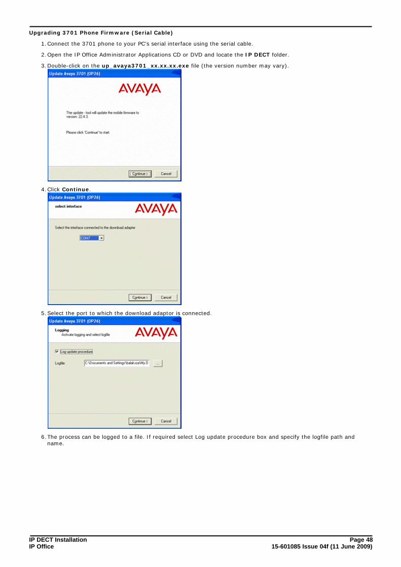
Upgrading 3701 Phone Firmware (Serial Cable)
1.Connect the 3701 phone to your PC’s serial interface using the serial cable.
2.Open the IP Office Administrator Applications CD or DVD and locate the IP DECT folder.
3.Double-click on the up_avaya3701_xx.xx.xx.exe file (the version number may vary).
4.Click Continue.
5.Select the port to which the download adaptor is connected.
6.The process can be logged to a file. If required select Log update procedure box and specify the logfile path andname.

IP DECT Installation Page 4915-601085 Issue 04f (11 June 2009)IP Office
Handset Installation: Upgrading the Phone Firmware
7.Click Continue.
8.When the update has completed, either exit the program or insert the next phone that requires upgrading to thecradle and restart the upgrade process.

IP DECT Installation Page 5015-601085 Issue 04f (11 June 2009)IP Office
Upgrading 3711 Phone Firmware (Serial Cable)
1.Connect the 3711 phone to your PC’s serial interface using the serial cable.
2.Open the IP Office Administrator Applications CD or DVD and locate the IP DECT folder.
3.Double-click on the up_avaya3711_v3_and_v2_xx.xx.xx.exe file (the version number may vary).
4.Click Next. The application will search for the phone and then display its details.
5.If the connected 3711 is identified by the Installer, the 3711 is switched off.
6.Press c-key and the up part of the key.
7.When the update has completed, either exit the program or insert the next phone that requires upgrading to thecradle and restart the upgrade process.

IP DECT Installation Page 5115-601085 Issue 04f (11 June 2009)IP Office
Handset Installation: Upgrading the Phone Firmware
4.2 Adding Handsets to ADMMThis process below is divided into a number of stages. These are:
1.Obtaining the unique IPEI serial number of an IP DECT handset.
2.Creating an entry for the handset in the ADMM configuration.
3.Enabling handset subscription on the ADMM.
4.Subscribing handsets.
5.Disabling further handset subscription on the ADMM.
Pre-Requisites
1. ¨ Base Station InstallationThe processes detailed in Section B: Base Station Installation should be completed.
2. ¨ Handsets ChargedThe handsets must be charged before starting this process.
Information Required
1. ¨ User DetailsUser extension numbers and name. These must be unique and should not overlap with any existing IP Officeextensions.
2. ¨ ADMM DetailsIP address, name and password for ADMM web access.
Tools Required
1. ¨ PC Web BrowserUsed for web access to the ADMM base station.

IP DECT Installation Page 5215-601085 Issue 04f (11 June 2009)IP Office
Process
1. Stage 1: Obtaining the Handset IPEIThe IPEI is a serial number unique to each handset. An entry for the handset with the matching IPEI must exist inthe ADMM configuration before the handset can subscribe to the IP DECT system. For 3701 and 3711 handsets theIPEI can be obtained as follows:
1.1. Power on the handset.
1.2. Press Menu.
1.3. Select System | Subscription | IPEI. Note the number displayed.
1.4. Press Esc to return the phone to the normal standby menu.
2. Stage 2: Adding Handset Details to the ADMM ConfigurationAn entry must be created that matches the IP Office extension and user
2.1. Using a web browser connect to the ADMM base station.
2.2. Select IP DECT Handsets.
2.3. Select New.
2.3.1.For 3701 and 3711 handsets leave the Type as Auto.
2.3.2.Enter the Name for the user as set in the IP Office configuration.
2.3.3.Enter the Number that matches the extension number set in the IP Office configuration.
2.3.4.Enter the IPEI number as it is shown on the handset.
2.3.5.The Authentication Code is used during the subscription of the phone to the IP DECT system.
2.3.6.Ensure that you have a note of the Name, Number, IPEI and Authentication Code.
2.3.7.Click OK.
2.4. Repeat the above steps for any other handsets being added.
3. Stage 3: Enabling Handset Subscription on the IP DECT system.This stage of the process enables phone subscription:
3.1. Click Subscribe. A green tick mark icon is displayed while handset subscription is enabled.
4. Stage 4: Subscribing HandsetsThis stage describes the sequence for 3701 and 3711 phones. For other GAP compatible phone types to subscriberefer to the phone manufacturers documentation.
4.1. On the 3701/3711 phone press Menu.
4.2. Select System and press OK. No Subscription is displayed.
4.3. Press New.
4.4. Enter the PARK number of the IP DECT system and then press go on.
4.5. Enter the authentication code enter for the handset in the ADMM configuration.
4.6. Press OK.
4.7. If subscription is successful, the name and number as set in the ADMM configuration are displayed.
4.8. It should be possible to make test calls between the handset and other IP Office extensions.
4.9. Repeat for another other phones that need to be subscribed.

IP DECT Installation Page 5315-601085 Issue 04f (11 June 2009)IP Office
Handset Installation: Adding Handsets to ADMM
5. Stage 5: Disable Phone SubscriptionWe recommend that you disable the subscription of further phones.
5.1. Using the web browser to access the ADMM configuration, on the IP DECT Handset page the subscribed handsetsshould now be listed.
5.2. Click Stop to disable further subscriptions.
5.3. Logout of the ADMM configuration.
6. If the Auto-create extension option was selected for the IP DECT line in the IP Office configuration, the aboveactions will have automatically created new extension and user entries within the IP Office configuration. Thoseentries can be edited as per any normal IP Office user. If Auto-create extension was not enabled, proceed to 4. IPOffice User Creation in order to manually create entries for the IP DECT handsets within the IP Officeconfiguration.
54

IP DECT Installation Page 5415-601085 Issue 04f (11 June 2009)IP Office
4.3 IP Office User CreationFor each IP DECT handset, matching extensions have to be created within both the IP Office configuration and the ADMMconfiguration. This section covers the creation of IP DECT extensions (and their associated users) within the IP Officeconfiguration.
The DECT Extension menu will only be active if at least one IP DECT Line has been configured. Up to 120 IP DECTextensions may be created.
· Important: Auto-Create ExtensionIf Auto-create extension is enabled on the IP DECT line settings, much of this process can be ignored. The IPOffice will automatically create an extension and user entry when the handset configured in the ADMM issubscribed. The user entry can then be configured as per any normal IP Office user.
Warning
1.Adding extensions to the IP Office configuration manually requires the IP Office to be rebooted. This will end anycurrent calls and services on the IP Office.
Information Required
· ¨ Handset User DetailsUser extension numbers and name.
· ¨ IP Office LoginService user name and password with Administrator or Manager security group rights for the IP Office. Thoserights are required in order to create new extensions.
Tools Required
· ¨ IP Office ManagerPC running the IP Office Manager application.
Process
1.Start IP Office Manager and click to receive the configuration from the IP Office system.
2.In the left hand pane click on Extension.
3.Right-click on Extension and select New and then IP DECT Extension.
4.The extension details are shown in the main right-hand pane.
5.In Base Extension enter the extension number that the IP DECT extension should use. This must be a uniquenumber not used by any other IP Office extension or hunt group. Allowable numbers are up to 9 digits. Refer tothe IP Office Manager help for full details on number ranges usable.
6.The remaining fields on the Extn tab are for information only.

IP DECT Installation Page 5515-601085 Issue 04f (11 June 2009)IP Office
Handset Installation: IP Office User Creation
7.Select the IP DECT tab.
· The DECT Line ID should already show the ADMM base station IP address.
· Select the Message Waiting Lamp Indication Type to either On or None.
· Click OK.
8.If the extension number is new, IP Office Manager will prompt Do you wish to create an associated user?.Select Yes.
9.Manager will automatically jump to the User entries section and show the details for the new user.
10.On the User tab, the following fields must be set:
· NameEnter a short (less than 15 characters) name. This name must match that which will be entered for the sameextension in the ADMM configuration.
· Full NameEnter a full name of up to 32 characters for the user. This is the main name that will be seen in most IP Officeapplications and on phone displays.
· ExtensionThis should match the extension number of the extension just added to the IP Office configuration.
· Other settings can be adjust as normal for any IP Office user. Note that IP DECT phones do not supportbutton programming so entries made there will not be used.
· Click OK.
11.Repeat this process for any other IP DECT extensions that need to be added.
12.Click on to save the configuration back to the IP Office. Note that this will require the IP Office to reboot andso will end all currently connected calls and services.


IP DECT Installation Page 5715-601085 Issue 04f (11 June 2009)IP Office
ADMM Web Access
Chapter 5.

IP DECT Installation Page 5815-601085 Issue 04f (11 June 2009)IP Office
5. ADMM Web AccessThe ADMM base station acts as an HTTP web server. This allows it to be accessed and configured across the networkusing a web browser.
· The web server uses the ADMM's IP address and port 80.
· Access is restricted to one active session at a time with an idle time out (5 minutes).
· The browser used for service access has to be at least Microsoft Internet Explorer 6.0 or Mozilla Firefox 1.0 andmust have frame support, javascript and cookies enabled. If either javascript is missing, or cookies are notallowed, a warning message will be displayed.
Logging on to the ADMM Web Server
1.Start the web browser.
2.Enter http:// followed by the IP address of the ADMM base station. If necessary add : followed by the portnumber that has been configured.
3.Enter the User Name and Password for the ADMM base station. The default user name and password are craftand crftpw.
4.The ADMM only allows one user access at a time to configure the system. If the ADMM configuration is alreadybeing accessed you will receive the message "ADMM Locked The Avaya IP Dect Mobility Manager is alreadyin use by another user".
5.Once logged in the user name and password can be changed through the System | User Account menu.63

IP DECT Installation Page 5915-601085 Issue 04f (11 June 2009)IP Office
ADMM Web Access:
6.If login is successful the ADMM configuration Home menu is displayed. You can return to this menu from any sub-menu by clicking on Home.
7.If this interface is idle for 5 minutes you will be automatically logged off.
8.To exit the system manually, click Logout.
· If the browser is closed without logging out first, the service access will be blocked for 5 minutes.

IP DECT Installation Page 6015-601085 Issue 04f (11 June 2009)IP Office
5.1 System MenuThis option is used to access a series of menus for various system settings.
1.Using a web browser login to the ADMM base station.
2.From the Home menu select System.
3.Select the required sub-menu.

IP DECT Installation Page 6115-601085 Issue 04f (11 June 2009)IP Office
ADMM Web Access: System Menu
5.1.1 System | System SettingsThe system settings cover global settings of the ADMM such as the system name.
1.Using a web browser login to the ADMM base station.
2.From the Home menu select System.
3.Select System Settings.
· RestartThis command allows you to restart the ADMM base stations and also to erase the current configuration ifrequired. See Restarting .
· General Settings
· System NameThis is an information field that can be useful to identify system when comparing configuration filesoffline.
· Authentication Code
· DECT Settings
· EncryptionThis option can only be used on systems consisting of RFP32 and or RFP34 base stations. If encryption isenabled and an RFP31 or RFP33 base station is present, its DECT wireless interface will not be activated.Note that enabling/disabling encryption causes all base stations to restart.
· DECT MonitorThis check box is used to enable or disable output of information to the DECT Monitor application. Thisoption should only be enable when required as DECT Monitor imposes a load on the ADMM base station.See Maintenance | DECT Monitor .
· Regulatory DomainTo define where the IP DECT is used the parameter regulatory domain has to be configured. Existinginstallations are updated to the default value “EMEA (ETSI)”. To setup an FCC compliant installation thevalue has to be set to “US (FCC/CI)”. ETSI compliant IP Base Stations are inactive and can not beactivated if the regulatory domain is set to “US (FCC/CI)” and vice versa.
85
90

IP DECT Installation Page 6215-601085 Issue 04f (11 June 2009)IP Office
· SyslogThe IP DECT base stations can output RFC 3164 syslog messages. Those messages can be viewed usingstandard Syslog tools (not part of the IP Office or IP DECT software suite).
· IP AddressEnter the IP address of the Syslog server.
· PortEnter the port on which the Syslog server is configured to receive Syslog messages.
· Date and TimeThe time and date are shown on the display of 3711 phones when idle. If SNTP is not being used to obtain thedate and time, the current values can be entered through this menu. The date and time has to be configuredafter every restart of the ADMM base station.
· Time ZoneThe time zone is shown here but is configured through the IP Regions menu.
· Local TimeEnter the current time.
· Locale DateEnter the current date.

IP DECT Installation Page 6315-601085 Issue 04f (11 June 2009)IP Office
ADMM Web Access: System Menu
5.1.2 System | User AccountThis menu is used to set the name and password used for web access to the ADMM.
1.Using a web browser login to the ADMM base station.
2.From the Home menu select System.
3.Select User Account.
4.Enter the User Name and Password required. Note that the values are case sensitive.

IP DECT Installation Page 6415-601085 Issue 04f (11 June 2009)IP Office
5.1.3 System | Time ZoneThe local time and date displayed on the 3711 phone, depend on the IP region the IP DECT phones are located in. EachIP region is configured to a certain time zone. Based on this, the local time can be calculated individually (depending onthe current date and the daylight savings time rule).
In the time zone section, the ADMM provides all available time zones. They are set per default with their known daylightsavings time rules adjusted to the Universal Coordinated Time (UTC). The difference to the UTC time is shown in the“UTC Difference” column. In case of a daylight savings time rule, this is also marked for each time zone.
It is possible to change the time zone rules for up to five time zones.
1.Using a web browser login to the ADMM base station.
2.From the Home menu select System.
3.Select Time Zones.
4.The Default button sets all time zones back to the default values and deletes the changed time zone rules in theconfiguration file.
5.The standard time and the daylight savings time (DST) settings of a time zone can be changed. Changed rules aremarked with a bold time zone name in the table. The changes are saved in the configuration file and are restoredafter each ADMM boot up.
6.Locate the time zone that needs to be adjusted.
7.Click on the icon to the left.
8.Edit the time zone as required.

IP DECT Installation Page 6515-601085 Issue 04f (11 June 2009)IP Office
ADMM Web Access: System Menu
9.If the time zone has no DST only the UTC difference can be configured. For the DST, both points of time (begin ofstandard time and begin of daylight savings time) have to be specified exactly. A certain day in the month or acertain week day in a month can be used, as shown in the following figure:
10.Click OK.

IP DECT Installation Page 6615-601085 Issue 04f (11 June 2009)IP Office
5.1.4 System | SNMPEach base station can act as an SNMP agent. If SNMP is enabled through the ADMM, the base stations will give alarminformation to an SNMP server at the specified address and allows SNMP management software such as HP OpenView toview the network.
The base station SNMP agent supports SNMPv1 and SNMPv2c. The agent does not support MIB-II write access, SNMPv2-MIB read/write access, NET-SNMP-MIB read/write access, NET-SNMP-AGENT-MIB read/write access and SNMPv3. Forfurther details see SNMP in the Maintenance section.
1.Using a web browser login to the ADMM base station.
2.From the Home menu select System.
3.Select SNMP.
· General Settings
· Read-only communityThe SNMP management software must belong to the same community in order to be able to view the IPDECT base stations.
· System ContactThis is a general information field.
· Trap HandlingSelecting this option enables the base station to send SNMP alarms.
· Trap CommunityThe SNMP community name that must be matched by the SNMP server.
· Trap Host IP AddressThe IP address to which base stations should send SNMP alarm events if Trap Handling is enabled.
4.Click OK.
93

IP DECT Installation Page 6715-601085 Issue 04f (11 June 2009)IP Office
ADMM Web Access: System Menu
5.1.5 System | BackupThe ADMM web interface allows copies of the configuration to be save and loaded to the browser PC.
1.Using a web browser login to the ADMM base station.
2.From the Home menu select System.
3.Select Backup.
· SaveThis option will start a dialogue to save a copy of the current configuration to a file on the browser PC.
· Restore ConfigurationRestoring a previously saved configuration. Use of this option causes the ADMM base station to restart. Thefirst field is used to locate the configuration file to upload to the ADMM base station.
· RestoreClicking this button uploads the indicted file and resets the ADMM.

IP DECT Installation Page 6815-601085 Issue 04f (11 June 2009)IP Office
5.2 IP RegionsAn IP Region is used to define a relation between a IP Base Station and the IP Trunks which have to be used tocommunicate with the Avaya communication server. For IP Office only one IP region should be created. The IP regionmust be created before IP DECT base stations or an IP trunk can be added.
1.Using a web browser login to the ADMM base station.
2.From the Home menu select IP Regions.
· To view the settings of an existing region click on the icon.
· To delete a region click on the icon.
· A crossed-out icon indicates that the IP region contains IP trunks and base stations. All related IP trunksand base stations must be deleted before an IP region can be deleted.
3.To add a region click New.
4.The IP Region settings shown when editing or adding a region appear in a separate window.
· The National CPN Prefix and International CPN Prefix fields are not supported for IP Office

IP DECT Installation Page 6915-601085 Issue 04f (11 June 2009)IP Office
ADMM Web Access: IP Regions
5.3 IP DECT Base StationsThis menu lists all configured IP DECT base stations including the ADMM base station.
· ClustersTo ensure the hand over of a phone between base stations during a call, all base in a physical area need tosynchronize with each other by exchanging wireless signals. See Base Station Synchronization . This is achievedby placing the IP Base Stations sufficiently close to each other that each base station is in range of at least oneother base station. There may be cases where the base stations on one part of the LAN network are not insynchronization range of the other base stations. Each group of base stations needs to be given a cluster number.The ADMM will then not try to synchronize groups of base stations that are not within range of each other.
1.Using a web browser login to the ADMM base station.
2.From the Home menu select IP DECT Base Stations
3.The base stations are grouped into their configured clusters and sorted by their Ethernet addresses.
· The IP DECT Station running ADMM is displayed in bold font.
· Each IP Base Station is identified by its Ethernet address (6 byte hex format, colon separated). The Ethernetaddress is unique and can be found on the back of the chassis.
· The icon indicates a base stations whose MAC address has been entered into the Licensing menu aspart of the IP DECT systems licensing. Removal or loss of communication with such a base station will affectoperation of the whole IP DECT system.
· The Active and Synchronous fields are used to indicate the state of operation of base stations. See thetable below.
4.A base station can be deleted by pressing the trash icon . However, the IP Base Station running ADMM cannotbe deleted. Caution should be taken not to delete base stations that have been used as part of the systemslicensing or which are providing a synchronization signal to another base station that does not have a alternatebase station with which to synchronize.
5.New base stations are added by clicking on New. Similarly existing base stations can be edited by clicking on the
icon. Note that base stations cannot be added until the IP Regions have been added to the configuration.
· MAC AddressThis is normally printed on a label on the base station. The MAC address of existing connected base stationscannot be changed.
· LocationThis is used for information only. It allows you to note where the base station is physically located. The stringbe up to 20 characters.
22
84
68

IP DECT Installation Page 7015-601085 Issue 04f (11 June 2009)IP Office
· IP RegionThe IP region with which the base station operates. The regions need to be created before the base stationcan be assigned.
· DECT SettingsThis option can be used to disable the DECT service of a base station. This option is used chiefly for the ADMMbase station. If the ADMM is used for DECT, up to 50 simultaneous calls are supported on the IP DECTsystem. If the ADMM base station is not providing DECT, up to 100 simultaneous calls are supported on the IPDECT system.
· DECT ClusterThis is the physical area cluster to which the base station belongs. All the base station in the cluster should begiven the same number. The ADMM base station uses this value to determine which base station shouldsynchronize with each other.
6.Click OK.

IP DECT Installation Page 7115-601085 Issue 04f (11 June 2009)IP Office
ADMM Web Access: IP DECT Base Stations
IP DECT Base Station States
For each IP Base Station the state of the DECT subsystem is displayed. The states are:
· SynchronousThe IP Base Station is up and running. The IP Base Station recognises and is recognised by other IP Base Stationsin its cluster through its air interface and delivers a synchronous clock signal to the phones.
· Asynchronous but activeThe IP DECT Base Station has not been able to synchronize to its neighbours yet. No DECT communication ispossible, nevertheless the IP Base Station has already been able to connect the ADMM. This phase should only lastfor a few seconds after starting up the IP Base Station or the ADMM. If this state lasts longer, it maybe anindication of a hardware or network failure.
· SearchingThe IP Base Station has lost synchronization to its neighbours. No DECT communication is possible. This phaseshould only last for a few seconds after starting up the IP Base Station or the ADMM. If this state lasts longer or isre-entered after being in a synchronous state, it maybe an indication of a bad location of the IP Base Station.
· InactiveThe IP Base Station is connected to the ADMM but the air interface has not been switched on yet. For any IP BaseStation with activated DECT functionality, this phase should last only for a few seconds after starting up the IPBase Station. If this state lasts longer, it may indicate a hardware failure.
· Not connectedThe IP Base Station was configured but has not connected to the ADMM yet.
The IP address column displays the current IP address of an IP Base Station.
ADMM/Base Station Software Version Check
All base stations within the IP DECT system must run the same version of software as the ADMM base station. When theBase Stations connect to the ADMM they submit their software version. If this version differs from the ADMM softwareversion the Base Station connection attempt is rejected.
This could happen when using several DHCP servers with different IP DECT software versions. In this case the BaseStation is marked with an error message. Moreover a global error message is displayed on the IP Base Station list webpage if at least one version mismatch has been found.
Upgrading the ADMM\Base Station Software
The latest version of the software can be found on the Administration CD.
1.Backup the ADMM configuration using the System | Backup menu.
2.Install the upgrade software on the TFTP server.
3.If using DHCP amend the DHCP settings to match the new software file name. If the base stations were staticallyconfigured, use the ADMM Configurator tool to amend the file name stored by each base station.
4.Restart the ADMM. The TFTP server will upgrade the ADMM at startup.
5.Restart any existing IP Base Stations.
6.Through the IP DECT Base Stations menu check that there are no software version conflicts.
67

IP DECT Installation Page 7215-601085 Issue 04f (11 June 2009)IP Office
5.4 IP TrunksAn IP trunk must be defined for the signalling between the ADMM base station and the IP Office. The same trunk is alsodefined in the IP Office configuration. Only one trunk is supported for IP DECT with IP Office.
IP trunks can be added to the system by clicking New. A pop up window appears, providing the configuration of a newtrunk. Before a trunk can be added, the associated IP region has to be already configured.
· NameEnter a name that will help identify the connection.
· ADMM Port.For IP Office operation this is 1720.
· CS IP AddressThis is the IP address of the H.323 Gatekeeper. For IP Office operation this is the LAN1 or LAN2 IP address of theIP Office.
· CS PortFor IP Office operation this is 1720.
· IP RegionEnter the number assigned for the IP Region.
The same pop up window can be opened for an existing IP Trunk by pressing the tool icon of the appropriate trunk.
An IP trunk can be deleted by pressing the trash icon . A similar pop up window asks for confirmation showing thecurrent configuration of this IP Trunk.

IP DECT Installation Page 7315-601085 Issue 04f (11 June 2009)IP Office
ADMM Web Access: IP Trunks
5.5 IP DECT HandsetsThis page shows all the know IP DECT extensions and allows subscription of those phones to the system.
· NewThis option is used to add the details of a new handset prior to its subscription, see below.
· SubscribeClick this option to allow the subscription of currently unsubscribed handsets. When that action is no longerrequired click Stop to disable any further subscriptions.
· If the Auto-create extension option is enabled on the IP DECT line in the IP Office configuration, subscribinga new handset will create new extension and user entries in the IP Office configuration.
· SearchDisplays a menu that allows you to search for a particular handset in the list of handset by using either its numberor IPEI.
· UpdateTo force an update of date/time, voicemail number or the changes to Media Server System Features (MSSF) itemsimmediately on handsets, click Update.
51

IP DECT Installation Page 7415-601085 Issue 04f (11 June 2009)IP Office
A new phone can be added to the system by pressing New. The following pop up window appears allowing theconfiguration of a new phone:
· TypeThe type of phone will be automatically detected (in the case of the 3701 and 3711 phones). If the type of phonecannot be detected, it will automatically be set to WT9620.
· If the type (WT9620, 20DT, GAP) of phone is configured before subscription and the type cannot be detectedthen the configured type will be used.
· NameThis name is displayed on the handset when idle. This field is optional. If the handset is subscribed, changes to thephone will not take effect until the phone is subscribed again.
· NumberThis is the extension number to assign to the handset. The number used must conform to the dialing plan rulesrequired by the IP Office.
· IPEIThis is a serial number unique to the handset. For 3701 and 3711 it can be displayed as follows. For other types ofDECT handsets refer to the manufacturers instructions. Enter the number including spaces, as shown on thephone.
· Power on the handset.
· Press Menu.
· Select System | Subscription | IPEI. Note the number displayed.
· Press Esc to return the phone to the normal standby menu.
· Authentication CodeThis code is used during handset subscription. It is optional. If not set, when the Authentication Code is requestedon the handset press OK without entering a code. The Authentication Code can only be changed if the phone is notsubscribed.
A similar pop up window appears when configuring an existing phone by pressing the tool icon . The only difference isthe delete subscription checkbox. If this option is selected, the phone will be un-subscribed.
Deleting a phone can be done by pressing the trash icon. A pop up window appears and asks for confirmation. Whenan IP DECT handset is deleted from ADMM web interface, the subscription should also be removed from the phone at thesame time, otherwise the phone may appear to be subscribed and have an extension number when that is not the case.

IP DECT Installation Page 7515-601085 Issue 04f (11 June 2009)IP Office
ADMM Web Access: IP DECT Handsets
5.6 System FeaturesThis set of menus provide options that may need to be changed to maximize IP DECT system feature interaction with thetelephone system, in this case IP Office.
1.Using a web browser login to the ADMM base station.
2.From the Home menu select System Features.
3.Select the required sub-menu.
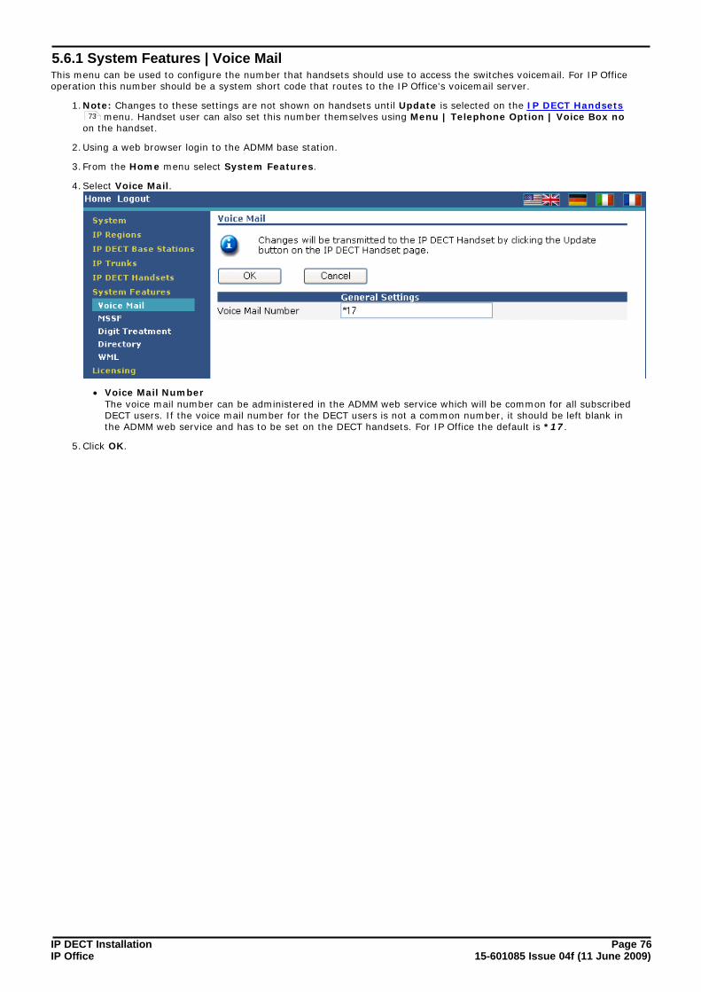
IP DECT Installation Page 7615-601085 Issue 04f (11 June 2009)IP Office
5.6.1 System Features | Voice MailThis menu can be used to configure the number that handsets should use to access the switches voicemail. For IP Officeoperation this number should be a system short code that routes to the IP Office's voicemail server.
1.Note: Changes to these settings are not shown on handsets until Update is selected on the IP DECT Handsets menu. Handset user can also set this number themselves using Menu | Telephone Option | Voice Box no
on the handset.
2.Using a web browser login to the ADMM base station.
3.From the Home menu select System Features.
4.Select Voice Mail.
· Voice Mail NumberThe voice mail number can be administered in the ADMM web service which will be common for all subscribedDECT users. If the voice mail number for the DECT users is not a common number, it should be left blank inthe ADMM web service and has to be set on the DECT handsets. For IP Office the default is *17.
5.Click OK.
73

IP DECT Installation Page 7715-601085 Issue 04f (11 June 2009)IP Office
ADMM Web Access: System Features
5.6.2 System Features | Media Server FeaturesThis menu allows you to configure the media server feature available to the IP DECT phones and the associated signallingto the media server (IP Office) necessary for those features. The settings are is sub-divided into those available to thephone when idle and those available when active.
These are features available through the display menus on the phones. The use of normal DTMF dialing to activate IPOffice user and system short codes is not affected by this menu.
On the phone the options configured on this menu and set as Active are accessed as follows. Press either Menu in idlestate or Option in active state to show menu items on the display. Features are not configured and set as Active are notdisplayed.
1.Note: Changes to these settings are not shown on handsets until Update is selected on the IP DECT Handsets menu.
2.Using a web browser login to the ADMM base station.
3.From the Home menu select System Features.
4.Select Media Server System Features.
· ActiveFor items where a Feature Access Code has been configured, this control enables or disables display of thefeature on IP DECT phones.
· MuteFor some features, select this option if it is required to mute the phone when the feature is being used.
· Feature Access CodeThe active flag for a feature can only be set if the Feature Access Code field is configured. The field shouldbe configured with the appropriate digits (0 to 9, * and #) necessary to active the feature on the IP Office.These should match the system short code for the feature.
· When configuring the Media Server System Features, the ADMM options may not be the same as theMedia Server. For example; the Call Forward Busy/No reply has a combined option in the ADMM. OnIP Office, this is two separate options. You can choose either option by entering the relevant FeatureAccess Code.
· The following are the default IP Office system short codes.
· Call Pickup: *30
· Directed Call Pickup: *32*
· Send All Calls Enable: *08
· Send All Calls Cancel: *09
73

IP DECT Installation Page 7815-601085 Issue 04f (11 June 2009)IP Office
· Call Forward All: *01
· Call Forward Busy/No Reply: *03 or *05
· Call Forward Cancel: *00
· Call Unpark: *38*
· Transfer: Not supported by short code.
· Enquiry: Not supported by short code.
· Conference: *47
· Call Park: *37*
5.Click OK.

IP DECT Installation Page 7915-601085 Issue 04f (11 June 2009)IP Office
ADMM Web Access: System Features
5.6.3 System Features | Digit TreatmentThis menu allows you to configure the IP DECT system to alter the dialing resulting from numbers received via thedirectory and WML features. The digit treatment takes place before the number is transmitted to the handset menu. Thedigits are treated in two steps:
· First all invalid characters like space or hyphens are removed from the number. For example +49 (30) 6104 4492will be substituted by +493061044492.
· Next the best match is searched for within the prefixes listed in the Digit Treatment table. When a match is found,the prefix is substituted by the indicated substitute from the table. For example, if the best match for +493061044492 is the prefix +49306104 with the substitute ' ' (blank); the result is 4492.
For IP Office installations this menu is unlikely to be required, necessary digit translation being performed for all types ofphones by the IP Office.
1.Using a web browser login to the ADMM base station.
2.From the Home menu select System Features.
3.Select Digit Treatment.
4.To delete an existing entry click on the icon next to the entry.
5.To edit an existing entry click on the icon next to the entry.
6.To add an entry click on New.
· Up to 128 entries.
· Each prefix may be composed of the digits 0 to 9 and the characters * and #. In conformance to LDAPstandards the first character of prefixes may be +. Up to 15 digits per prefix are possible. Spaces are notallowed.
· Each substitute may be composed of the digits 0 to 9 and the characters * and #.
· Entries may be valid for several regions. The region numbers have to be separated by , (comma), forexample 1,2,3 or may be defined as range by - (hyphen), for example 1-3.

IP DECT Installation Page 8015-601085 Issue 04f (11 June 2009)IP Office
5.6.4 System Features | DirectoryThe IP DECT system can provide the IP DECT phones with access to a directory of numbers, obtained either using TFTPor LDAP.
For IP Office installations, the desirable option is to configure TFTP access to obtain the directory of IP Office users andthe IP Office external number directory.
1.Note: Changes to these settings are not shown on handsets until Update is selected on the IP DECT Handsetsmenu.
2.Using a web browser login to the ADMM base station.
3.From the Home menu select System Features.
4.Select Directory.
5.The Type setting indicates the method to be used to obtain the directory. The options are None (no directory),TFTP or LDAP. The other settings available will adjust according to the selected Type.
73

IP DECT Installation Page 8115-601085 Issue 04f (11 June 2009)IP Office
ADMM Web Access: System Features
TFTP Based Directory
The following fields for obtaining a TFTP based directory can be edited, if the Type is set as TFTP.
· Server NameSet this to the IP address of the IP Office control unit.
· Server Port: Default = 69.The default is the port on which the IP Office control unit listens for TFTP requests.
· Internal List: Default = nasystem/user_list7This is the path and file. It can be up to 127 characters. The default is the IP Office user list (nasystem/user_list7).
· If a source other than the IP Office is selected, the expected format for each line is User Name, ExtensionNumber, Full Name.
· External List: Default = nasystem/dir_listThis is the path and file. It can be up to 127 characters. The default is the IP Office directory (nasystem/dir_list).If a source other than the IP Office is selected, the expected format for each line is Name, Number with entriesseparated by \n.
· Update IntervalThis sets the frequency with which the lists are requested from the server. A value of zero indicates not to updatethe lists after the first update. Clicking the OK and then Update initiates an immediate reading from server.

IP DECT Installation Page 8215-601085 Issue 04f (11 June 2009)IP Office
LDAP Based Directory
The following fields for obtaining an LDAP based directory can be edited, if the Type is set as LDAP.
· Server Name and PortThe LDAP server name or IP address.
· Server Port: Default 389.The LDAP port on that server. Note SSL is not supported.
· Search BaseThe LDAP query string to retrieve the names from the company database and store the information on the ADMMbase station. For example ou=people,o=avaya.com.
· User Name and PasswordA user name and password if required. The default blank entries assume anonymous binding.
· Search Type: Default = First NameThe search attribute, select from either Surname (sn) and First Name (default) or Full Name (cn).
· Display Attributes: Default = First NameYou can select from either Surname (sn) and First Name (default) or Full Name (cn).
· Server Search Timeout: Default = 10 secondsThe set time in the range 1 to 99 seconds, at which the search will be terminated.

IP DECT Installation Page 8315-601085 Issue 04f (11 June 2009)IP Office
ADMM Web Access: System Features
5.6.5 System Features | WMLThe 3711 phone supports WAP WML web site browsing. This menu can be used to enable WML support and to add up to9 pre-set WML web site URL's to the phone's directory.
1.Note: Changes to these settings are not shown on handsets until Update is selected on the IP DECT Handsetsmenu.
2.Using a web browser login to the ADMM base station.
3.From the Home menu select System Features.
4.Select WML.
5.The WML active option is used to enable or disable all WML support. The default is disabled.
6.To delete an existing entry click on the icon next to the entry.
7.To edit an existing entry click on the icon next to the entry.
8.To add an entry click on New.
9.Each pre-configured URLs is administered by filling the following fields:
· NameThis is the name to be shown in the phone menu.
· URLThe URL of the WAP WML web site. http//172.17.4.64/waptest.
· Active FlagThis control can be used to enable/disable the entry. The default is disabled.
10.Click OK.
11.Click OK.
73

IP DECT Installation Page 8415-601085 Issue 04f (11 June 2009)IP Office
5.7 ADMM LicensingThe ADMM web interface can be used to view and manage the IP DECT system licenses. The license is both based on andcontrols the number of base stations supported
1.Note: Making changes to the license settings causes the IP DECT system to restart and disconnects all calls inprogress.
2.Using a web browser login to the ADMM base station.
3.From the Home menu select Licensing. This screen shows the status of the licenses entered with the ADMMconfiguration.
· The red cross means that one of the base stations whose MAC address is being used for licensing is notcommunicating with the ADMM base station. Check that the base station is running and the ADMM's IPaddress is correct.
· A green tick indicates that the base station being used for licensing is communicating with the ADMM basestation.

IP DECT Installation Page 8515-601085 Issue 04f (11 June 2009)IP Office
ADMM Web Access: ADMM Licensing
5.8 Restarting the ADMMThis menu can be used to manually restart the ADMM if required. Doing this will terminate all current calls on the IP DECTsystem.
1.From the Home menu select System.
2.Select System Settings
3.Click Restart.
4.The Discard All Settings option can be used to reset the configuration. Only select this option if absolutelynecessary.
5.Click OK.
6.The following message is displayed:
7.The ADMM web login page is displayed after the ADMM restarts.


IP DECT Installation Page 8715-601085 Issue 04f (11 June 2009)IP Office
Maintenance
Chapter 6.

IP DECT Installation Page 8815-601085 Issue 04f (11 June 2009)IP Office
6. Maintenance6.1 Phone MaintenanceThe IP DECT 3701 and 3711 handsets provide a number of maintenance and diagnostics functions. These are accessedby pressing Menu and then dialing the sequence R***76#.
Checking the 3701 Phone Firmware Version
1.Press Menu.
2.Enter R***76#.
3.Select Version Number.
4.Press OK.
5.The display will show the software and the hardware level of the phone.
6.To stop the test, switch the phone off and on again.
3711 Phone Auto Call Test Mode
In this mode, the phone calls a specified number cyclically. You can use this feature to generate traffic for test purposes.This mode is also active if the phone is on the charger.
1.Press Menu.
2.Enter R***76#.
3.Select Auto Call Test and press OK.
4.Enter the phone number to call and press OK.
5.Enter a number of seconds between two calls and press OK.
6.Enter a number of seconds a call shall be active and press OK. The test will be started automatically.
7.To stop the test, switch the phone off and on again.
3711 Phone Auto Answer Test Mode
In this mode, the phone answers incoming calls automatically. You can use this feature for test purposes. This mode isalso active if the phone is on the charger.
1.Press Menu.
2.Enter R***76#.
3.Select Auto Answer and press OK.
4.Enter a number of seconds the phone shall ring before it will answer the call and press OK.
5.Enter a number of seconds a call shall be active and press OK. The test will be started automatically.
6.To stop the test, switch the phone off and on again.
Phone Master Reset
Erase all the phone settings.
1.Press Menu.
2.Enter R***76#.
3.Select Master Reset and press OK.
4.Press OK again.

IP DECT Installation Page 8915-601085 Issue 04f (11 June 2009)IP Office
Maintenance: Phone Maintenance
Change the Phone Security PIN
1.Press Menu.
2.Enter R***76#.
3.Select Change PIN and press OK.
4.Enter the new PIN and press OK.
5.Enter the new PIN again and press OK.
Site Survey Mode
This function puts the phone in the 'site survey mode'. While in this mode the phone can also receive a call to allowaudible checking of the call quality as you move around the survey area. .
1.Press Menu.
2.Enter R***76#.
3.Select Site Survey.
4.Press OK.
5.Press Esc.
6.The phone displays the IP Base Stations and the actual field strength of the receiving signal in dBM.
· RFPIThis line shows the PARK number of the IP DECT system to which the phone is connected.
· FEThis line shows the frame errors detected by the portable part (PP = the phone) and the fixed part (FP = thebase station to which it is connected). Occasional framing errors are acceptable.
· -dBM and RPNThese two lines show the signal strength (-dBm) and the Base Station ID (RPN) of the base station providingeach signal. The Base Station ID's match those shown on the IP DECT Base Station screen when accessing theADMM web configuration. Note that the signal strength is in negative numbers, for example 70 is a weakersignal than 50.
7.To leave site survey mode, switch the phone off and on again.

IP DECT Installation Page 9015-601085 Issue 04f (11 June 2009)IP Office
6.2 DECT MonitorDECT Monitor is an Windows program that gives a real time overview of the IP DECT system including the operation ofphones and base stations.
This tool imposes a processing load on the ADMM and so should only be used when absolutely required. It operation isenabled/disabled though the DECT monitor setting within the ADMM configuration.
DECT Monitor Software
1. The DECT Monitor software (DECTNetmonitor.exe) is located in the IPDECT folder on the IP Office AdministrationApplications CD and DVD. The files does not need to be installed.
Enabling Use of DECT Monitor
1.Using a web browser login to the ADMM base station.
2.From the Home menu select System.
3.Select System Settings.
4.Select DECT Monitor in order to allow use of the DECT Monitor application.
· Important Only enable this option when required and always disable it after monitoring is complete. The outputting ofinformation for the DECT monitor application imposes a processing load on the ADMM.
Running DECT Monitor
1.Enable DECT Monitor in the ADMM configuration as described above.
2.Double-click on DECTNetmonitor.exe.
3.Click OK.
4.Enter the IP address of the ADMM base station and click OK.

IP DECT Installation Page 9115-601085 Issue 04f (11 June 2009)IP Office
Maintenance: DECT Monitor
5.On DECT monitor has established communication with the ADMM base station, information about the IP DECTsystem is displayed. The level of detail can be adjusted and details can be recorded to a log file is required.
6.When use of DECT Monitor is completed, close the application.
7.Disable the DECT Monitor setting within the ADMM base station configuration.

IP DECT Installation Page 9215-601085 Issue 04f (11 June 2009)IP Office
DECT Monitor Notes
When all links have been established, the DECT data of the system are automatically read out and entered in the tables RFP-Table and PP-Table. This procedure is called Config Request.
Next, the defined trace options (Event Mask) are sent to the ADMM. The options which are sent to the ADMM are alwaysthose which were active the last time the program was exited.
If the trace option Transaction establish/release is activated, the ADMM will deliver all existing transactions.
The ADMM system delivers the desired trace data. The user can either communicate with the program interactively (seebelow) or activate a log file in which to record the data.
Following this initialization, the user can carry out the following modifications:
· The trace settings can be modified using the menu item Options-Event Mask. Transmission to the ADMM takesplace after confirmation of the settings with OK.
· A Config Request can be sent again to the ADMM.
· A log file can be activated.
· By means of various dialogues, the configuration data of the PPs, RFPs and control modules can be displayed andstored in ASCII files.
The following information is displayed dynamically in the tables:
· Transactions between PP and PABX system. These are displayed in both tables. Simple transactions are displayedin black on a white background; during hand over, both transactions involved are displayed in white on a redbackground.
· The Location Registration and Detach events are displayed in the tables for approximately 1-2s after theiroccurrence (light green background), if possible. There is no display in the FP table if there is no column free fordisplay. If the event has already been displayed, it can be overwritten at any time. The events are not displayed ifthey occur during an on-going transaction. Irrelevant of whether the events are displayed in the tables, they arealways entered in the FP/PP-events window and in the log file (provided that this is open).
The following colour scheme is used for display of the RFP in the RFP table:
· RFP grey-blue RFP is not active (not connected or disturbance).
· RFP black RFP is active.
The data of an RFP is displayed in a dialogue box after clicking on the respective RFP field in the RFP table. The statisticsdata of the RFP can be called up from this dialogue box.
The following colour scheme is used for display of the PP in the PP table:
· PP black PP is enrolled. It is assumed that the PP can be reached.
· PP blue PP can presumably not be reached. Detach was received, or when an attempt was made to reach a PP, the PP didnot answer.
· PP grey-blue PP not enrolled.
The data of a PP is displayed in a dialogue box after clicking on the respective PP field in the PP table.
The Sync Info child window contains all IP Base Stations and shows their synchronization and relation states to eachother. Selecting the IP Base Stations with the right mouse button the user can change visibility views and can even forcea re-synchronization of an IP Base Station.
There are several optional child windows selectable. They are all listed below and give some more information about theIP DECT systems. Mostly they are statistics and for internal use only.

IP DECT Installation Page 9315-601085 Issue 04f (11 June 2009)IP Office
Maintenance: DECT Monitor
6.3 SMNPIn order to manage a large network of IP DECT Base Stations, an SNMP agent is offered in each IP DECT Base Station.
· The SNMP agent responds to SNMPv1 and SNMPv2c read requests for the standard MIB-II objects.
· The agent supports both SNMPv1 and SNMPv2c traps ('coldStart', 'nsNotifyShutdown', 'authenticationFailure’ and'nsNotifyRestart').
· Decoding SNMP messages with your network management system or MIB browser always requires the publiclyavailable IETF MIB definitions which can be downloaded.
SNMP Management Information
The SNMP agent responds to SNMPv1 and SNMPv2c read requests for the standard MIB-II objects. The MIB-II contains11 object groups, see MIB_II.
· sysLocation corresponds to the location configured via web service. If this location is not configured sysLocation isset to “Location”.
· sysName is composed of MAC address and “IP Base Station” or “ADMM IP DECT Base Station” if the ADMM isrunning on this IP Base Station.
· sysUpTime - This value indicates the running time of the IP Base Station application software. It does not indicatethe running time of the operating system which does not correspond to the operational IP Base Station state. Thisvalue does not make a statement about the DECT network.
SNMP Traps
The agent supports both SNMPv1 and SNMPv2c traps.
· It sends a 'coldStart' trap when it first starts up.
· It sends an enterprise-specific trap 'nsNotifyShutdown' when it stops.
· It send an 'authenticationFailure' trap when it receives an SNMP request using an unknown community name.
· It send an enterprise-specific trap 'nsNotifyRestart' after being reconfigured. This is instead of the standard'coldStart' or 'warmStart' traps.
Decoding SNMP messages with your network management system or MIB browser always requires the publicly availableIETF MIB definitions.
· RFC1213-MIB
· RFC1212-MIB
· RFC1155-SMI
· SNMPv2-MIB
· SNMPv2-CONF
· SNMPv2-TC
· SNMPv2-SMI.
Enterprise-specific traps can be decoded using the definitions in:
· NET-SNMP-MIB
· NET-SNMP-AGENT-MIB.

IP DECT Installation Page 9415-601085 Issue 04f (11 June 2009)IP Office
6.4 Syslog OutputThe ADMM and the IP Base Stations are capable of propagating syslog messages conforming to RFC 3164. This featuretogether with the IP address of a host collecting these messages can be configured.
The output of Syslog events is enabled using one of the following methods:
· DHCP using public option 227 and 228.
· Local configuration via the ADMM Configurator tool.
· Setting syslog daemon server and port via ADMM base station web access.
Setting Syslog via DHCP or ADMM Configurator has the advantage that Syslog output is available in earlier states of IPBase Station start up.
The level of syslog messages in the default state allows the user, to have information on the general state of the systemand major failures. To increase the level for diagnostic reasons, it can be done via telnet user shell by increasing the SPYlevel of subsystems.
You can also read syslogs if you type the command logread within Telnet user shell.

IP DECT Installation Page 9515-601085 Issue 04f (11 June 2009)IP Office
Maintenance: Syslog Output
6.5 Base Station Telnet InterfaceEach IP Base Station, including the ADMM, can be accessed using Telnet. This allows for diagnostics and various actionswhen OMM is not available.
General Telnet Access
1.Open a Telnet session to the IP Base Station.
2.Username is iprfp.
3.Password is crftpw.
Welcome to IP RFP OpenMobility Avaya Version x.y.zFr Apr 29 12:34:06 CEST 2005Release(BUILD 0)172.30.111.232 login: iprfpPassword:Welcome to the system usershell!172.030.111.232 > help
4.Type help to get a command overview.
Checking the IP DECT Base Station Booter Version
You can display the version information of the IP Base Station booter using the base station telnet interface.
1. Start a Telnet session using the IP address of the IP Base Station.
2. Enter login: iprfp and password: crftpw.
3. Enter flash.
4. The display will show the software and the hardware level of the IP Base Station:> flashversion of initial booter : 2.0.12Version of booter 1 : 3.2.8Version of booter 2 : 3.2.8Hardware Revision : 51MAC address : 00:30:42:08:31:A4>
Manually Updating an IP Base Station Booter
If automatically updating the booter is not possible you can update the IP Base Station booter manually.
1. Start a telnet session using the IP address of the IP Base Station.
2. Enter login: iprfp and password: crftpw
3. Enter flash_update.
4. Enter flash_update a second time for two booters.
Checking the Local Configuration
You can display the local configuration settings of the IP Base Station, using the telnet interface of an IP Base Station.
1.Start a telnet session using the IP address of the IP Base Station.
2.Enter login: root and password: avaya12.
3. Enter local_db.
4.The display will show the local configuration settings of the IP Base Station:
>local_dbuse_local_cfg=1ip=172.30.111.234subnet=255.255.0.0siaddr=172.30.206.20boot_file=/omm_avaya.tftpommip=172.30.111.234

IP DECT Installation Page 9615-601085 Issue 04f (11 June 2009)IP Office
Removing the Local Configuration
You can remove the local configuration settings of the IP Base Station using the telnet interface of an IP Base Station.
1.Start a telnet session using the IP address of the IP Base Station.
2.Enter login: root and password: avaya12.
3.Enter local_db -c.
4.All local network settings are removed.
> local_db -c> local_db

IP DECT Installation Page 9715-601085 Issue 04f (11 June 2009)IP Office
Appendix
Chapter 7.

IP DECT Installation Page 9815-601085 Issue 04f (11 June 2009)IP Office
7. Appendix7.1 DHCP Server OperationA third-party DHCP server can be used to provide the IP address information required by the IP DECT base stations. Thetable below indicates the information that can be provided through DHCP.
Option Usage Notes
– IP Address Mandatory The IP address is taken from the yiaddr field in the DHCPmessage.
– Netmask Mandatory The IP netmask is taken from the subnet mask option (code 1).
– Gateway Mandatory The default gateway is taken from the router option (code 3).
– Boot file name Mandatory The boot image filename is taken from the file field in the DHCPmessage. If this field is empty, the default filename iprfp.bin isused.
– TFTP server Mandatory The TFTP server IP address is taken from the siaddr field in theDHCP message.
6 Domain Name Server Optional This option specifies the Domain Name System Servers availableto the client in order of preference. The minimum length for thisoption is 4 octets, and the length must always be a multiple of 4.
15 Domain Name Optional This option specifies the domain name that the client should usewhen resolving hostnames via the Domain Name System. Theminimum length is 1.
42 Network Time ProtocolServer
Optional This option specifies by IP address the NTP servers available tothe client in order of preference. The minimum length is 4 octetsand the length must always be a multiple of 4.
224 Magic String Mandatory The value of this option must be OpenMobility.
225 VLAN ID Optional Public option 225 (code 225) with a length of 2 bytes isinterpreted as VLAN ID. If this option is present the booter willstart over with releasing the current lease and issuing a newDHCP REQUEST, now using VLAN.
226 ADMM IP Address Mandatory The value is interpreted as ADMM IP address; the length must be4 bytes.
227 Syslog Server IP Address Optional The value is interpreted as the IP address of the syslog server,the length must be 4 bytes.
228 Syslog Server Port Optional The value is interpreted as the port the syslog server ismonitoring. The length must be 2 bytes.
The DHCP client request its own IP address using code 50. The DHCP client will select the DHCP server that offers thecurrently used IP address. Additionally, the mandatory options must be offered otherwise the DHCP OFFER is ignored bythe DHCP client.
The DHCP client selects the DHCP server according to the following rules:
· The public option (224) has a value equal to the string OpenMobility.
or
· The file field in the DHCP message has a sub string equal to ip_rfp.cnt.
If no matching reply is received, the DHCP client resends the request twice more after 1 second. The DHCP client will waitfor 1 minute before resending 3 requests again. If the DHCP client cannot accept a DHCP offer within 3 minutes, the IPDECT Base Station reboots.
Each application software comes with the latest released booter software. The application software will update the booterautomatically as long as the major release number of the booter software has not changed, e.g. booter software 2.1.2will not be automatically updated by booter SW 3.x.y, but booter software 3.0.0 will be automatically updated by bootersoftware 3.1.0.
The booter update of booters with major release number change, will be performed automatically when the DHCP clientin the application receives an DHCP OFFER with the public option 254 with a value UPDATE. This feature is currently notsupported by the IP Office DHCP server.

IP DECT Installation Page 9915-601085 Issue 04f (11 June 2009)IP Office
Appendix: DHCP Server Operation
7.2 802.1Q VLAN SupportThe IP Base Stations support VLANs according to IEEE 802.1Q.
VLAN can be administered either:
· On a per port basis of the LAN switch assuming that the IP Base Stations are connected to a single port of aswitched Ethernet environment.
or
· By setting a VLAN ID on the IP Base Station corresponding to the VLAN they should be operating in. In this caseVLAN tagging has to be set to the IP DECT base station. The following sections refer to this case only.
The benefit of VLAN tagging by the IP DECT Base Station, is to set 802.1p priority within Ethernet frames. The scope ofthe following description comprises VLAN tagging and obtaining the VLAN ID. Quality of Service mechanisms like 802.1ppriority and DiffServ are not covered in this section.
· IP DECT base stations are not be able to support VLAN ID 0 as described later in this section. Any other validVLAN ID can be configured.
· If 802.1Q tagging is enabled and a VLAN ID is configured, all traffic from an IP Base Station will be tagged withthis VLAN ID.
· Once a VLAN ID is set on the IP Base Station, incoming frames are only accepted if they are tagged as well.Therefore the switch port has to be configured as a tagged trunk for this VLAN.
· VLAN configuration can be done using DHCP or via OM Configurator.
· The usage of VLAN does influence the boot up process of the IP Base Station because VLAN configuration takesplace during the boot phase.
802.1Q VLAN tagging is enabled if the VLAN ID is set, either through Public Option 225 is using DHCP or through theADMM Configurator tool if using static addressing. If no VLAN ID is set, 802.1Q is disabled.
VLAN ID 0 means that the IP Base Station’s traffic belongs on the port/native VLAN. The Ethernet switch port to whichthe IP Base Station is connected must be configured to accept 802.1Q tagging for this to work, and the switch mustinterpret VLAN ID 0 as the port/native VLAN ID, as per the IEEE 802.1Q standard.
The packets from the IP Base Station are tagged with VLAN ID 0 and the packets send to the IP Base Station are taggedwith the port/native VLAN ID. This scenario does not work, because the IP Base Station supports only one VLANID in both directions. That means the VLAN ID in the receive direction must be the same as the senddirection.

IP DECT Installation Page 10015-601085 Issue 04f (11 June 2009)IP Office
VLAN and the Boot Phase of an IP Base Station
DHCP
Because the IP Base Station is not VLAN active during the beginning the start up two DHCP scopes are required (Thisprocedure applies regardless of the Ethernet switch being used):
The following scenario with arbitrary VLAN IDs details the steps an IP Base Station would go through in a typical dual-VLAN implementation.
Step A. DHCP scope within the native VLAN:
1.IP Base Station boots up and obtains an address on the native VLAN.
2.The data VLAN DHCP Public option 225 directs the IP Base Station to go to voice VLAN.
Step B. DHCP scope within the voice VLAN:
1.IP DECT Base Station releases the data VLAN address and obtains an address on the voice VLAN and all otherparameters.
2.The voice VLAN does not have the DHCP Public option 225, because an IP Base Station already on the voice VLANdoes not need to be directed to go there.
3. IP Base Station is operational on the voice VLAN.
If a reboot or power cycle occurs, the IP DECT Base Station returns to step A.
If an IP Base Station cannot obtain an address on the voice VLAN, due to network or DHCP problems, it falls backautomatically to untagged frames (native VLAN).
· Note: The IP Office DHCP server cannot be used for VLAN environments, only for native VLAN. Therefore, it canonly be used for step A, not step B.
Local Configuration of the IP DECT Base Stations
The ADMM Configurator has to be a member of the native VLAN for the first configuration.

IP DECT Installation Page 10115-601085 Issue 04f (11 June 2009)IP Office
Appendix: 802.1Q VLAN Support
7.3 IP Signalling and Media StreamTo establish a call between an IP phone and a DECT phone, the following IP streams must be established:
1.A signalling channel to and from the IP phone.
2.A signalling channel to and from the ADMM.
3.A control interface between the ADMM and the IP Base Station that has a connection to the DECT phone (known asthe primary IP Base Station).
4.A Real Time Protocol (RTP)/Real Time Control Protocol (RTCP) connection between the IP phone and the IP Officeand then a RTP/RTCP connection between the IP Office and the IP Base Station.
· If Direct Media is active for the IP Office IP DECT line configuration, RTP/RTCP connection is directly betweenthe IP phone and the IP Base Station.

IP DECT Installation Page 10215-601085 Issue 04f (11 June 2009)IP Office
To establish a call between two DECT phones, the same IP streams must be established as in the scenario before, exceptthe IP phone is not involved. If Direct Media is active, the RTP/RTCP connection is directly between that IP Base Station.The following figure illustrates this scenario:
A call from one DECT phone to another that resides on the same IP Base Station will loop back within the IP Base Station,if no IP Office is involved. So the call will not pass through to the local area network (LAN). Although the voice packetswill not impact LAN traffic, signal packets will.

IP DECT Installation Page 10315-601085 Issue 04f (11 June 2009)IP Office
Appendix: IP Signalling and Media Stream
If the DECT phone user is moving, the phone detects that another IP Base Station has a better signal strength and startsthe handover process. The media stream from the IP phone cannot move to the secondary IP Base Station, so theprimary uses the LAN to direct the voice to the secondary IP Base Station, as shown in the following figure.
As the phone user moves into the next IP Base Station zone of coverage, the phone detects that the IP Base Station hasa better signal strength. The media stream from the IP phone cannot move to the secondary IP Base Station, so theprimary IP Base Station uses the LAN to direct the voice to the new secondary IP Base Station, as shown below.

IP DECT Installation Page 10415-601085 Issue 04f (11 June 2009)IP Office
7.4 WML TagsThe ADMM and 3711 supports WML version 1.1 with the following major exceptions:
· WML images.
· The “multiple” attribute for the <select> tag.
· Softkeys, given the small display of the 3711 phone.
· WTAI click-to-dial applications are supported using the <a>, <anchor>, <onevent> and <do> tag.
The following are the WML tags and tag attributes supported for IP DECT usage.
Tag Attributes
<a> href, title, id
<anchor> Title, id
<br> id
<card> newcontext, onenterbackward, onenterforward. ontimer, ordered, title, id
<do> label, name, optional, type (except x-*), id
<go> accept-charset, href, method, sendreferer, id
<input> emptyok, format, maxlength, name, title, type, value, id
<onevent> id
<p> align, id
<prev> id
<select> ivalue, name, title, value, id
<setvar> name, value, id
<template> onenterbackward, onenterforward, ontimer, id
<timer> name, value, id
<wml> id

IP DECT Installation Page 10515-601085 Issue 04f (11 June 2009)IP Office
Appendix: WML Tags
7.5 IP DECT SAP CodesThis is not a definitive listing. The availability and support for particular items must be confirmed with the local Avayadistributor or reseller. In addition various IP DECT bundles may be available in different locales.
IP DECT Handsets and Handset Accessories
Handsets are supplied with 3 AAA rechargeable batteries and a charger. Region specific power adaptor for the chargermust be ordered separately.
Item Region SAP Code
IP DECT 3701 Handset EMEA 700346802
IP DECT 3711 Handset EMEA 700346810
North America 700430267
Belt Clip 700346885
Phone Charger for 3701/3711
Requires power adaptor below.
Global 700346828
Power Adaptor for Charger European 700346836
United Kingdom 700346844
Australia 700378318
North America 700430309
Rack mount 8-phone charger
Requires power adaptor below.
Global 700346851
Power Adaptor for Rack Mount Charger
Require region specific IEC60320 C13/C14 power cord ordered separately.
Global 700346869
Power Cord IEC60320 C13 Europe 700289762
United Kingdom 700289747
North America 700289770
IP DECT Phone Firmware Upgrade RS232 Serial Cable EMEA 700379688
IP DECT Phone Firmware Upgrade USB Cable North America 700436603
Leather Case for 3711 Global 700436629
IP DECT Headset for 3701/3711 Global 700346950

IP DECT Installation Page 10615-601085 Issue 04f (11 June 2009)IP Office
IP DECT Base Stations
Item Region SAP Code
RFP32 Indoor Base Station
Requires power adaptor or PoE. Note: These are not pre-licensed 'plug andplay' base stations, see below for those items.
North America 700430275
EMEA 700420789
Power Adaptor for RFP32 North America 700430291
Europe 700346901
United Kingdom 700346919
Australia 700378326
RFP34 Outdoor Base Station
PoE only. Note: These are not pre-licensed 'plug and play' base stations,see below for those items.
North America 700430283
EMEA 700420797
Outdoor Base Station Wall Mounting Kit Global 700378334
Outdoor Base Station Mast Mounting Kit (65mm) Global 700347156
Outdoor Base Station Mast Mounting Kit (>65mm) Global 700347172
External Dipole Aerial (pair) EMEA 700346935
External Beam Aerial (pair) EMEA 700346943
Mounting Kit for External Aerials EMEA 700347149
External Aerial Connection Cable (0.5m) EMEA 700347115
Plug and Play IP DECT Kits
Item Region SAP Code
IP DECT Starter Kit
Includes 2 RFP32 base stations.
North America 700436538
EMEA 700378995
RFP32 Upgrade Kit North America 700436579
EMEA 700436561
RFP34 Upgrade Kit North America 700436595
EMEA 700436587
IP DECT Site Survey Kits
Item Region SAP Code
IP DECT Survey Kit with Tripod
Includes custom RFP, 2 handsets, charger, charger power adaptor andtripod.
North America 700436512
IP DECT Survey Kit without Tripod
Includes custom RFP, 2 handsets, charger, charger power adaptor.
Europe 700378284
United Kingdom 700378292
Tripod for IP DECT Survey Kit Global 700378300
IP DECT Licenses
Item Region SAP Code
IP DECT License for 1 RFP All 700379027
IP DECT License for 2 RFP's All 700379035
IP DECT License for 3 to 5 RFP's All 700379043
IP DECT License for 6+ RFP's All 700379050
IP DECT License for upgrade from 1 to 2 RFP's All 700379068
IP DECT License for upgrade from 2 to 3-5 RFP's All 700379076
IP DECT License for Upgrade to 6+ RFP's All 700379084
IP DECT License Conversion from IP Office to CM All 700379167

IP DECT Installation Page 10715-601085 Issue 04f (11 June 2009)IP Office
Index
Index8802.1Q VLAN Support 99
AAbout
IP DECT Base Stations 9
IP DECT Wireless Solution 7
Adding Handsets 51
ADMM 51
Restarting 85
ADMM Licensing 43, 84
ADMM Setup 40Attributes Supported 104
BBackup 67
Base Station Coverage 20
Base Station Telnet Interface 95
CCreate
IP DECT Line 38
DDECT Monitor 90DHCP Server Operation 98
Digit Treatment 79
Directory 80
HHandsets
Adding 51
IIn
Logging 58
Installation Requirements 28IP 101
IP Base Station Synchronization 22
IP DECT 13, 14
IP DECT Base Station Configuration 69
IP DECT Base Stations About 9
IP DECT Handsets 73
IP DECT Licensing 15IP DECT Line
Create 38
IP DECT SAP Codes 105
IP DECT Software 18
IP DECT System Planning 23IP DECT Wireless Solution
About 7
IP Office User Creation 54IP Regions 68
IP Trunks 72
LLogging
In 58
MMedia Server Features 77Media stream 101
PPhone Firmware
Upgrading 47
Phone Maintenance 88
RRestarting
ADMM 85
SSMNP 93SNMP 66
Static Base Static Address Configuration 31
Syslog Output 94System 63, 64, 66, 67
System Capacities 16
System Features 75, 76, 77, 79, 80, 83
System Menu 60
System Settings 61
TTechnical Specification 17
TFTP Server Setup 30
Time Zones 64
UUpgrading
Phone Firmware 47
User Account 63
Using IP Office DHCP 34
VVoice Mail 76
WWML 83
WML Tags 104


IP DECT Installation Page 10915-601085 Issue 04f (11 June 2009)IP Office

IP DECT Installation Page 11015-601085 Issue 04f (11 June 2009)IP Office
Performance figures and data quoted in this document are typical, and must bespecifically confirmed in writing by Avaya before they become applicable to anyparticular order or contract. The company reserves the right to make alterationsor amendments to the detailed specifications at its discretion. The publication of
information in this document does not imply freedom from patent or otherprotective rights of Avaya or others.
Intellectual property related to this product (including trademarks) and registeredto Lucent Technologies have been transferred or licensed to Avaya.
All trademarks identified by the ® or ™ are registered trademarks or trademarks,respectively, of Avaya Inc. All other trademarks are the property of their
respective owners.
This document contains proprietary information of Avaya and is not to bedisclosed or used except in accordance with applicable agreements.
Any comments or suggestions regarding this document should be sent to
© 2009 Avaya Inc. All rights reserved.Avaya
Unit 1, Sterling Court15 - 21 Mundells
Welwyn Garden CityHertfordshire
AL7 1LZEngland.
Tel: +44 (0) 1707 392200Fax: +44 (0) 1707 376933
Web: http://marketingtools.avaya.com/knowledgebase