ip-centric methodology and specification language … · ip-centric methodology and specification...
TRANSCRIPT

IP-CENTRIC METHODOLOGY AND SPECIFICATION LANGUAGE
System Level Design of Embedded Systems
Daniel D. Gajski, Rainer Domer and Jianwen Zhu Department of Information and Computer Science
University of California, Irvine Irvine, California, USA
In this paper, we demonstrate the application of the specify-explore-refine (SER) paradigm for an IP-centric codesign of embedded systems. We describe the necessary design tasks required to map an abstract executable specification of the system to the architectural implementation model. We also describe the final and intermediate models generated as a result of these design tasks. The executable specification and its refinements should support easy insertion and reuse of IPs. Although several languages are currently used for system design, none of them completely meets the unique requirements of system modelling with support for IP reuse. This paper discusses the requirements and objectives for system languages and describes a C-based language called SpecC, which precisely covers these requirements in an orthogonal manner. Finally, we describe the design environment which is based on our codesign methodology.
1. Introduction
New technologies allow designers to generate chips with more than 10 million transistors on a single chip. The main problem at this complexity is designer productivity. Although the chip complexity measured in number of transistors per chip has increased at the rate of 60 percent per year in the past, the productivity measured in number of transistors designed per day by a single designer has increased only at the rate of 20 percent. This growing gap between the complexity and productivity rates may have the catastrophic effect of slowing down semiconductor industry.
One of the main solutions for solving this problem is increasing the level of abstraction in design of complex chips. The abstraction level increase should be reflected in descriptions, components, tools, and design methodology.
F. J. Rammig (ed.), Distributed and Parallel Embedded Systems© Springer Science+Business Media New York 1999
4 Methodology and Design with SpecC
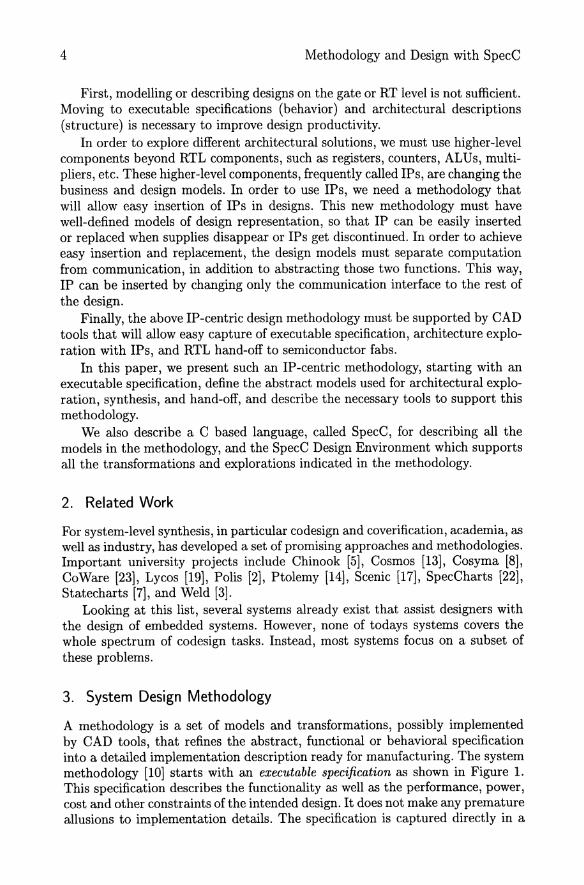
First, modelling or describing designs on the gate or RT level is not sufficient. Moving to executable specifications (behavior) and architectural descriptions (structure) is necessary to improve design productivity.
In order to explore different architectural solutions, we must use higher-level components beyond RTL components, such as registers, counters, ALUs, multipliers, etc. These higher-level components, frequently called IPs, are changing the business and design models. In order to use IPs, we need a methodology that will allow easy insertion of IPs in designs. This new methodology must have well-defined models of design representation, so that IP can be easily inserted or replaced when supplies disappear or IPs get discontinued. In order to achieve easy insertion and replacement, the design models must separate computation from communication, in addition to abstracting those two functions. This way, IP can be inserted by changing only the communication interface to the rest of the design.
Finally, the above IP-centric design methodology must be supported by CAD tools that will allow easy capture of executable specification, architecture exploration with IPs, and RTL hand-off to semiconductor fabs.
In this paper, we present such an IP-centric methodology, starting with an executable specification, define the abstract models used for architectural exploration, synthesis, and hand-off, and describe the necessary tools to support this methodology.
We also describe a C based language, called SpecC, for describing all the models in the methodology, and the SpecC Design Environment which supports all the transformations and explorations indicated in the methodology.
2. Related Work
For system-level synthesis, in particular codesign and coverification, academia, as well as industry, has developed a set of promising approaches and methodologies. Important university projects include Chinook [5], Cosmos [13], Cosyma [8], CoWare [23], Lycos [19], Polis [2], Ptolemy [14], Scenic [17], SpecCharts [22], Statecharts [7], and Weld [3].
Looking at this list, several systems already exist that assist designers with the design of embedded systems. However, none of todays systems covers the whole spectrum of codesign tasks. Instead, most systems focus on a subset of these problems.
3. System Design Methodology
A methodology is a set of models and transformations, possibly implemented by CAD tools, that refines the abstract, functional or behavioral specification into a detailed implementation description ready for manufacturing. The system methodology [10] starts with an executable specification as shown in Figure l. This specification describes the functionality as well as the performance, power, cost and other constraints of the intended design. It does not make any premature allusions to implementation details. The specification is captured directly in a

Methodology and Design with SpecC
-------- -----------------1
Synthesis flow 1
Architecture exploration
Behavior partitioning
Channel partitioning
Variable partitioning
1
1
Analysis and validation flow
Validation of algOrithm and functionality
Estimation
1
I 1
1
1
1
1
1
1
1
Validation of )------+-+----,---1 functionality and
1
1
1
1
Communication synthesis
1
I 1
1
1
1
1
1
1
1 1 ______ -
1
1
1
1
I I I 1
I I I 1
1
1
I I 1
Protocol selection
Transducer synthesis
Protocol in lining
Manufacturing
--------1
1
1
1
1
1
I
I
I 1
I I I I I 1
I
synchronization
Estimation
Validation of functionality and
performance
Estimation
Validation of timing and
performance
Estimation
5
--------1 1
1
1
L ______________________ J L ______________________ J
Figure 1. The codesign methodology in the Spece Design Environment
formal specification language such as SpecC (see Section 4.3), that supports different models in the methodology.
Since designers do not like to learn the syntax and semantics of a new language, the executable specification can be captured with a graphical editor that generates the specification from well-known graphical forms, such as block diagrams, connectivity tables, communication channels, timing diagrams, bubble

6 Methodology and Design with SpecC
charts, hierarchical trees, scheduling charts, and others. Such a graphical editor must also provide support for manual transformations of one model to another in the methodology.
As shown in Figure 1, the synthesis flow of the codesign process consists of a series of well-defined design steps which will eventually map the executable specification to the target architecture. In this methodology, we distinguish two major system level tasks, namely architecture exploration and communication synthesis.
Architecture exploration includes the design steps of allocation and partitioning of behaviors, channels and variables. Allocation determines the number and the types of the system components, such as processors, ASICs and busses, which will be used to implement the system behavior. Allocation includes the reuse of intellectual property (IP), when IP components are selected from the component library.
Then, behavior partitioning distributes the behaviors (or processes) that comprise the system functionality amongst the allocated processing elements, whereas variable partitioning assigns variables to memories and channel partitioning assigns communication channels to busses. Scheduling is used to determine the order of execution of the behaviors assigned to the processors.
Architecture exploration is an iterative process whose final result is the definition of the system architecture. In each iteration, estimators are used to evaluate the satisfaction of the design constraints. As long as any constraints are not met, component and connectivity reallocation is performed and a new architecture with different components, connectivity, partitions, schedules or protocols is evaluated.
After the architecture model is defined, communication synthesis is performed in order to obtain a design model with refined communication. The task of communication synthesis includes the selection of communication protocols, synthesis of interfaces and transducers, and inlining of protocols into synthesizable components. Thus, communication synthesis refines the abstract communications between behaviors into an implementation.
It should be noted that the design decisions in each of the tasks can be made manually by the designer, e. g. by using an interactive graphical user interface, as well as by automatic synthesis tools.
The result of the synthesis flow is handed-off to the backend tools, shown in the lower part of Figure 1. The software part of the hand-off model consists of C code and the hardware part consists of behavioral VHDL or C code. The backend tools include compilers, a high-level synthesis tool and an interface synthesizer. The compilers are used to compile the software C code for the processor on which the code is mapped. The high-level synthesis tool is used to synthesize the functionality mapped to custom hardware. The interface synthesizer is used to implement the functionality of interfaces needed to connect different processors, memories and IPs.
During each design step, the design model is statically analyzed to estimate certain quality metrics such as performance, cost and power consumption. This design model is also used in simulation to verify the correctness of the design at the corresponding step. For example, at the specification stage, the simulation
Methodology and Design with SpecC 7
model is used to verify the functional correctness of the intended design. After architecture exploration, the simulation model will verify the synchronization between behaviors on different processing elements (PEs). After communication synthesis, the simulation model is used to verify the performance of the system including computation and communication.
At any stage, if the verification fails, a debugger can be used to locate and fix the errors. Usually, standard software debuggers can be used which provide the ability to set break points anywhere in the source code and allow detailed state inspection at any time.
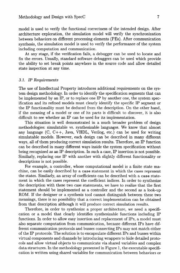
3.1. IP Requirements
The use of Intellectual Property introduces additional requirements on the system design methodology. In order to identify the specification segments that can be implemented by an IP, or to replace one IP by another one, the system specification and its refined models must clearly identify the specific IP segment or the IP functionality must be deduced from the description. On the other hand, if the meaning of a model or one of its parts is difficult to discover, it is also difficult to see whether an IP can be used for its implementation.
This situation is well demonstrated in a much broader problem of design methodologies: simulatable vs. synthesizable languages. We know that almost any language (C, C++, Java, VHDL, Verilog, etc.) can be used for writing simulatable models. However, each design can be described in many different ways, all of them producing correct simulation results. Therefore, an IP function can be described in many different ways inside the system specification without being recognized as an IP description. In such a case, IP insertion is not possible. Similarly, replacing one IP with another with slightly different functionality or descriptions is not possible.
For example, a controller, whose computational model is a finite state machine, can be easily described by a case statement in which the cases represent the states. Similarly, an array of coefficients can be described with a case statement in which the cases represent the coefficient indices. In order to synthesize the description with these two case statements, we have to realize that the first statement should be implemented as a controller and the second as a look-up ROM. If the designer or a synthesis tool cannot distinguish between these two meanings, there is no possibility that a correct implementation can be obtained from that description although it will produce correct simulation results.
Therefore, in order to synthesize a proper architecture, we need a specification or a model that clearly identifies synthesizable functions including IP functions. In order to allow easy insertion and replacement of IPs, a model must also separate computation from communication, because different IPs have different communication protocols and busses connecting IPs may not match either of the IP protocols. The solution is to encapsulate different IPs and busses within virtual components and channels by introducing wrappers to hide detailed protocols and allow virtual objects to communicate via shared variables and complex data structures. In the methodology presented in Figure 1, the executable specification is written using shared variables for communication between behaviors or

8 Methodology and Design with SpecC
processes, while models used for architecture exploration use virtual components and channels for easy insertion and replacement of IPs. The final communication model exposes the protocols and uses again shared variables to describe individual wires and busses used in communication. Thus, the architecture exploration is performed on the model that clearly separates computations (behaviors) from communication (channels) and allows a plug-and-play approach for IPs.
(a)
(b)
(e) rE<1~C I>I(CtE I ~ DT~ G
Figure 2. Channel inlining: (a) two synthesizable behaviors connected by a channel, (b) synthesizable behavior connected to an IP, (c) a synthesizable behavior connected to an IP through an incompatible channel.
However, there is a difference between functions defined in a channel and functions in a behavior. While the functions of a behavior specify its own functionality, the functions of a channel specify the functionality of the caller, in other words, when the system is implemented, they will get inlined into the connected behaviors or into transducers between the behaviors. When a channel is inlined, the encapsulated variables are exposed serving as communication media, and the functions become part of the caller. This is shown in Figure 2(a) where the

Methodology and Design with SpecC 9
channel C connecting behaviors A and B is inlined, assuming that A and B will be implemented as custom hardware parts. In such custom parts, the computation and communication will be realized by the same datapath and controlled by one controller.
The situation is different when a behavior is not synthesizable, such as in a processor core with a fixed protocol. This can be modelled using a wrapper which is a channel encapsulating a fixed behavior while providing higher-level communication functions that deal with the specific protocol of the internal component. For example, a MPEG decoder component with a wrapper can be used by other behaviors simply by calling the decode function provided by the wrapper. Figure 2(b) shows the inlining of the wrapper in component A allowing the communication between A and IP to use the IP protocol. On the other hand, whenever two channels (or wrappers) encapsulating incompatible protocols need to be connected, as shown in Figure 2(c), an interface component or transducer has to be inserted into which the channel functions will be inlined during communication refinement.
4. The Language
With this generic methodology in mind, Section 4.1 discusses the requirements and goals for system description languages and Section 4.2 compares traditional languages with these requirements. Since none of the languages supports all concepts a new modelling language called SpecC is proposed and presented in Section 4.3.
4.1. Modelling Language Requirements
For the codesign methodology presented above, it is desirable that one language is used for all models at all stages. Such a methodology is called homogeneous in contrast to heterogeneous approaches [14, 23], where a system is specified in one language and then is transformed into another, or is represented by a mixture of several languages at the same time.
This homogeneous methodology does not suffer from simulator interfacing problems or cumbersome translations between languages with different semantics. Instead one set of tools can be used for all models and synthesis tasks are merely transformations from one program into a more detailed one using the same language. This is also important for reuse, because design models in the library can be used in the system without modification (''plug-and-play'') and a new design can be used directly as a library component.
System design places unique requirements on the specification and modelling language being used. In particular the language must be
1. executable, 2. modular and 3. complete.
1. Executability of the language is of crucial importance for simulation. The system specification must be validated to assure that exactly the intended

10 Methodology and Design with SpecC
functionality is captured. Simulation is also necessary for the intermediate design models whose functionality must be equivalent to the behavior of the model before the refinement.
2. Modularity is required to clearly separate functionality from communication, which is necessary in a model at a high level of abstraction. It also enables the decomposition of a system into a hierarchical network of components. Behavioral hierarchy is used to decompose a system's behavior into sequential or concurrent subbehaviors, whereas structural hierarchy decomposes a system into a set of interconnected components. Modularity is also required to support design reuse and the incorporation of intellectual property. During refinement, modularity helps to keep changes in the system description local so that other parts of the design are not affected. For example, communication refinement should only replace abstract channels with more detailed ones without modifying the components using these channels. The locality of changes makes refinement tools simpler and the generated results more understandable.
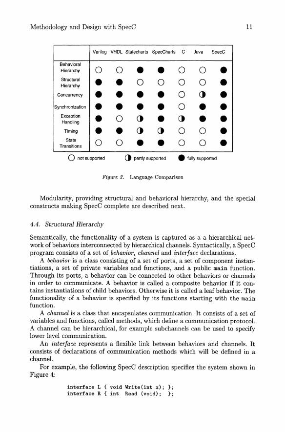
3. Completeness is obviously a requirement. A system language must cover all concepts commonly found in embedded systems. In addition to (a) behavioral and (b) structural hierarchy this includes (c) concurrency, (d) synchronization, (e) exception handling and (f) timing, as discussed in detail in [9]. For explicit modelling of Mealy and Moore type finite state machines, (g) state transitions have to be supported. Furthermore, it is desirable that these concepts are organized orthogonally (independent from each other) so that the language can be minimal. In addition to these requirements, the language should be easy to understand and easy to learn.
4.2. Traditionallanguages
Most traditional languages lack one or more of the requirements discussed in Section 4.1 and therefore cannot be used for system modelling without problems. Figure 3 lists examples of current languages [25, 12, 7, 22, 27, 1, 29] and shows which requirements they support and which are missing.
Because the traditional languages are not sufficient, a new language must be developed, either from scratch or as an extension of an existing language. The SpecC language [6] represents the latter approach as it is built on top of C.
4.3. The SpecC language
This section introduces the SpecC language and shows how SpecC covers all the requirements discussed before. SpecC is a superset of ANSI-C. C was selected because of its high acceptance in software development and its large library of already existing code.
A SpecC program can be executed after compilation with the SpecC compiler which first generates an intermediate C++ model of the program that is then compiled by a standard compiler for execution on the host machine.
Methodology and Design with SpecC 11
Verilog VHDL Statecharts SpecCharts C Java SpecC
Behavioral Hierarchy 0 0 • • 0 0 • Structural • • 0 0 0 0 • Hierarchy
Concurrency • • • • 0 () • Synchronization • • • • 0 • •
Exception • 0 () • () • • Handling
Timing • • () () 0 0 • State 0 0 • • 0 0 • Transitions
o not supported () partly supported • fully supported
Figure 3. Language Comparison
Modularity, providing structural and behavioral hierarchy, and the special constructs making SpecC complete are described next.
4.4. Structural Hierarchy
Semantically, the functionality of a system is captured as a a hierarchical network of behaviors interconnected by hierarchical channels. Syntactically, a SpecC program consists of a set of behavior, channel and interface declarations.
A behavior is a class consisting of a set of ports, a set of component instantiations, a set of private variables and functions, and a public main function. Through its ports, a behavior can be connected to other behaviors or channels in order to communicate. A behavior is called a composite behavior if it contains instantiations of child behaviors. Otherwise it is called a leaf behavior. The functionality of a behavior is specified by its functions starting with the main function.
A channel is a class that encapsulates communication. It consists of a set of variables and functions, called methods, which define a communication protocol. A channel can be hierarchical, for example subchannels can be used to specify lower level communication.
An interface represents a flexible link between behaviors and channels. It consists of declarations of communication methods which will be defined in a channel.
For example, the following SpecC description specifies the system shown in Figure 4.:
interface L { void Write(int x); }; interface R {int Read (void); };

12 Methodology and Design with SpecC
12 :zi
riJ I~ [:; ~
B p1 c2 p2
/ " c1 l'... ~
IZ~ [:;~ 12~ [:;~ [:;~ [:;~
p1 p2 p3 p1 p2 p3
b1 b2
Figure 4. Basic Structure of a SpecC Model
channel C implements L, R {
int Data: bool Valid:
void Write(int x) { Data = x: Valid = true: }
int Read(void)
};
{ while(! Valid) waitfor(10): return(Data): }
behavior Bl(in int pl, L p2, in int p3) { void main(void)
{ /* '" */ p2.Write(pl): } }:
behavior B2(out int pl, R p2, out int p3) {
void main(void) { /* ... */ p3 = p2.Read(): }
}:
behavior B(in int pl, out int p2) {
int cl: C c2: Bl bl(pl, c2, cl): B2 b2(cl, c2, p2):
void main(void) { par { bl.main(): b2.main(): } }
}:
The example system specifies a behavior B consisting of two subbehaviors b1

Methodology and Design with SpecC 13
Sequential Concurrent Pipelined
x x x
CJ ---------
LJ ---------
CJ (8) (b) (c)
Figure 5. Behavioral Hierarchy
and b2 which execute in parallel and communicate via integer cl and channel c2. Thus structural hierarchy is specified by the tree of child behavior instantiations and the interconnection of their ports via variables and channels. Behaviors define functionality, and the time of communication, whereas channels define how the communication is performed.
4.5. Behavioral Hierarchy
The composition of child behaviors in time is called behavioral hierarchy. Child behaviors can either be executed sequentially or concurrently. Sequential execution can be specified by standard imperative statements or as a finite state machine with explicit state transitions. Concurrent execution is either parallel or pipelined.
For example, we can specify a behavior being the sequential composition of the child behaviors using sequential statements, as shown in Figure 5(a), where X finishes when the last behavior C finishes. Second, we can use the parallel composition using the par construct, as shown in Figure 5(b), where X finishes when all its child behaviors A, B and C are finished. Also, pipelined composition is supported using the pipe construct, as shown in Figure 5(c), where X starts again when the slowest behavior finishes.
Syntactically, behavioral hierarchy is specified in the main function of a composite behavior. For example, with a, b, and c being instantiated child behaviors, the sequence of calls
a.main(); b.main(); c.main();
simply specifies sequential execution of a, b, c. The par and pipe statements specify concurrent execution. For example,
par { a.main(); b.main(); c.main(); }

14 Methodology and Design with SpecC
executes a, b, c in parallel, whereas
pipe { a.main(); b.main(); c . main(); }
specifies execution in a pipelined fashion (a in the first iteration, a and b in the second, ... ). The par statement completes when its last statement finishes, the pipe statement implicitly specifies an endless loop.
SpecC also supports explicit specification of state transitions. For example
fsm { a: { if (x > 0) break; if (x <= 0) goto b; }
b : { if (y > 0) goto a; if (y == 0) goto b; }
c: { break; } }
specifies the state transitions of a finite state machine model with three behaviors a, b, c. Implicitly the first label in the fsm statement specifies the initial state (a). The FSM exits when a break statement is executed.
In summary, behavioral hierarchy is captured by the tree of function calls to the behavior main methods.
4.6. Synchronization
Concurrent behaviors usually must be synchronized in order to be cooperative. In SpecC, a built-in type event serves as the basic unit of synchronization. Events can only be used as arguments to wait and notify statements (or with exceptions as explained in Section 4.7). A wait statement suspends the current behavior from execution until one of the specified events is notified by another behavior. The notify statement triggers all specified events so that all behaviors waiting on one of these events can resume their execution.
(a)
interface ILeft ( void write( int val ); };
interface IRight ( int read( void ); );
channel CShared( void) implements I Left, IRight (
(b)
int storage; bool valid; event wakeup; void write( int val ) {
storage = val; valid = true; notify( wakeup); )
int read( void) { while ( !valid )
waitt wakeup ); valid = false; return storage; } };
Figure 6. Example for simple Shared Memory Channel
For example, Figure 6 shows a simple shared memory channel CShared that, in addition to a valid bit, uses the event wakeup to allow only synchronized

Methodology and Design with SpecC
e1
void main( void) { try { x.mainO; }
e2
trap( e1 ) { y.mainO; } trap( e2 ) { z.mainO; } }
(a)
e1
void main( void) { try { x.mainO; }
e2
interrupt( e1 ) { y.mainO; } interrupt( e2 ) { z.mainO; } }
(b)
Figure 7. Exception handling: (a) abortion, (b) interrupt.
15
accesses to its storage. With this channel, it is assured that a consumer will always get valid data.
4.7. Exception Handling
SpecC provides support for two types of exceptions, namely abortion (or trap) and interrupt, as shown in Figure 7.
The try-trap construct, illustrated in Figure 7(a), aborts behavior x immediately when one of the events el, e2 occurs. The execution of behavior x (and all its child behaviors) is terminated without completing its computation and control is transferred to behavior y in case of ei, to behavior z in case of e2. This type of exception usually is used to model the reset of a system.
On the other hand, the try-interrupt construct, as shown in Figure 7(b), can be used to model interrupts. Here again, execution of behavior x is stopped immediately for events el and e2, and behavior y or z, respectively, is started to service the interrupt. After completion of interrupt handlers y and z control is transferred back to behavior x and execution is resumed right at the point where it was stopped.
For both types of exceptions, in case two or more events happen at the same time, priority is given to the first listed event.
It should be noted that interrupt and abortion type exceptions can be mixed in SpecC. For example, the following code specifies a behavior B with a resetable child behavior bl and an interrupt handler b2.
behavior B (in event IRQ, in event RST) {
B_sub bi, b2;
void main(void) { try { bi.main(); }
16
};
4.8. Timing
Methodology and Design with SpecC
interrupt IRQ { b2.main(); } trap RST { b1.main(); }
}
In the design of embedded systems the notion of real time is an important issue. However, in traditional imperative languages such as C, only the ordering among statements is specified, the exact information on when these statements are executed, is irrelevant. While these languages are suitable for specifying functionality, they are insufficient in modeling embedded systems because of the lack of timing information. Hardware description languages such as VHDL overcome this problem by introducing the notion of time: statements are executed at discrete points in time and their execution delay is zero. While VHDL gives an exact definition of timing for each statement, such a treatment often leads to over-specification.
One obvious over-specification is the case when VHDL is used to specify functional behavior. The timing of functional behaviors is unknown until they are synthesized. The assumption of zero execution time is too optimistic and there are chances to miss design errors during specification validation. Other cases of over-specification are timing constraints and timing delays, where events have to happen, or, are guaranteed to happen in a time range, instead of at a fixed point in time, as restricted by VHDL.
SpecC overcomes this problem by differentiating between two types of timing information, exact timing and timing ranges. Exact timing is used when the timing is known, for example the execution delay of an already synthesized component. This is specified with a waitfor statement which suspends the execution of the current behavior for a specified time. The time is measured in real time units such as nanoseconds. Simulation time is only increased by wai tf or statements, other statements are always executed in zero time.
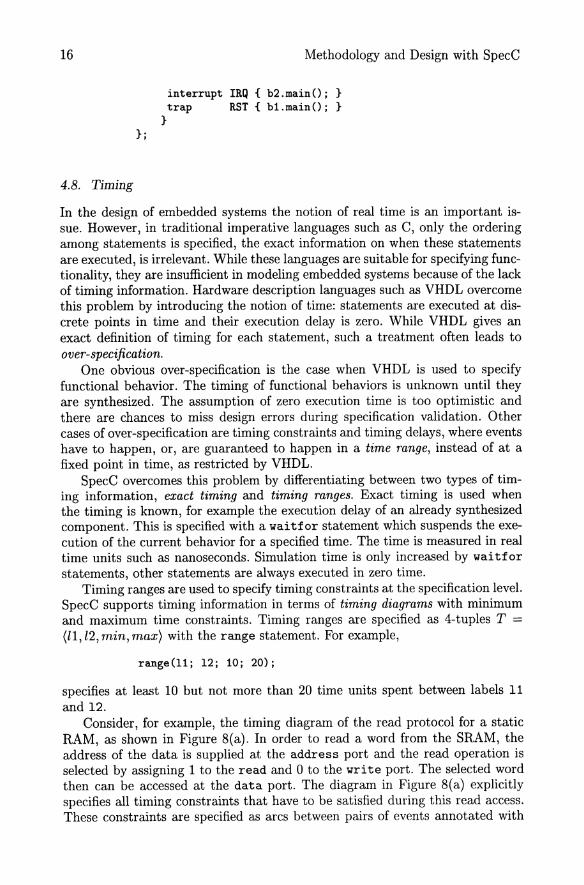
Timing ranges are used to specify timing constraints at the specification level. SpecC supports timing information in terms of timing diagrams with minimum and maximum time constraints. Timing ranges are specified as 4-tuples T = (ll, l2, min, max) with the range statement. For example,
range(11; 12; 10; 20);
specifies at least 10 but not more than 20 time units spent between labels 11 and 12.
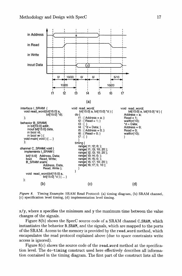
Consider, for example, the timing diagram of the read protocol for a static RAM, as shown in Figure 8(a). In order to read a word from the SRAM, the address of the data is supplied at the address port and the read operation is selected by assigning 1 to the read and 0 to the write port. The selected word then can be accessed at the data port. The diagram in Figure 8(a) explicitly specifies all timing constraints that have to be satisfied during this read access. These constraints are specified as arcs between pairs of events annotated with
Methodology and Design with SpecC 17
I I I I I I I
I I I I I I I
I I I I
~ a , I , in Address I I I , , I , I I I , , I , I I I , , I , I
~ I , , , , , I , , , , , , , in Read
, , , , , , , , , , , , , , , , , , , , , , , , , , , , in Write , , , , , , , , , , , , , , , , , , , , , , , ,
Cd) ,
, , , , inout Data , , , , , , , , , , , , , , , ,
: S/10 : , 01 , 10/20 , 01 01 , : .. "," ".- .. :- .. : ~ , , I , , , , , ,
10120 , ,
10120 , , , , , , .. ... ,
. - • , , , , , t1 t2 tS t4 tS tEl t7
(a)
interface I_SRAM ( void read_word ( void read_word( void read_word(bit[1S:0) a,
bit[1S:0) *d); };
behavior B_SRAM( in bit[1S:0) addr, inout bit[1S:0) data, in bool rd, in bool wr) (
void main( void) { ... } };
channel C_SRAM( void) implements LSRAM (
};
bit[1S:0) Address, Data; bool Read, Write; B_SRAM sram(
Address, Data, Read, Write);
void read_word(bit[1S:0) a, bit[1S:0) *d ) { ... }
(b)
bit[1S:0) a, bit[1S:0) *d ) { dol
t1 : { Address = a; } t2 : { Read = 1; } t3: { } t4 : { *d = Data; } tS : { Address = 0; } t6 : { Read = 0; } t7: { } }
timing ( range( t1; t2; 0; ); range( t1 ; t3; 10; 20 ); rangel t2; t3; 10; 20 ); range t3; t4; 0; ); range t4· ts· o· ). range( tS; t7; 10; '20); range( t6; t7; S; 10); }
(c)
bit[1S:0] a, bit[1S:0) *d ) ( Address = a; Read = 1; waitfor(10); *d = Data; Address = 0; Read = 0; waitfor( 10); }
(d)
Figure 8. Timing Example: SRAM Read Protocol: (a) timing diagram, (b) SRAM channel, (c) specification level timing, (d) implementation level timing.
x/y, where x specifies the minimum and y the maximum time between the value changes of the signals.
Figure 8(b) shows the SpecC source code of a SRAM channel C.BRAM, which instantiates the behavior B_SRAM, and the signals, which are mapped to the ports of the SRAM. Access to the memory is provided by the read_word method, which encapsulates the read protocol explained above (due to space constraints write access is ignored).
Figure 8(c) shows the source code of the read_word method at the specification level. The do-timing construct used here effectively describes all information contained in the timing diagram. The first part of the construct lists all the
18 Methodology and Design with SpecC
events of the diagram, which are specified as a label and its associated piece of code, which describes the changes of signal values. The second part is a list of range statements, which specify the timing constraints between the events, as explained above.
In order to implement the protocol, scheduling has to be performed for each do-timing statement. Figure 8(d) shows the implementation of the read_word method after an ASAP scheduling is performed. All timing constraints are replaced by delays, which are specified using the waitfor construct.
4.9. Additional features
In addition to the concepts explained in the last sections, the SpecC language supports further constructs that are necessary for system-level design. First, SpecC provides explicit support for Boolean (bool) and bitvector (bi t [ : ] ) types, in addition to all types provided by ANSI-C.
Also, constructs for binary import of pre-compiled SpecC code and support of persistent annotation for objects in the language are provided. Since these constructs are beyond the scope of this paper, please refer to [6] for further details.
In conclusion, the Sections 4.4 to 4.8 show that the SpecC language satisfies the requirements of executability, modularity and completeness, as discussed in Section 4.l.
It has to be emphasized, that the advantage of SpecC lies in its orthogonal constructs which implement orthogonal concepts. All SpecC constructs are independent of each other, unlike for example signals in VHDL, which are used for synchronization, communication and timing. The SpecC language covers the complete set of system concepts with a minimal set of constructs. Therefore it is easy to learn and easy to understand.
5. The System
We have developed the SpecC Environment as shown in Figure 9. The design is specified with the help of the SpecC Editor which provides a graphical user interface (GUI). The SpecC Editor is also used for displaying the system models at different design stages and allows the designer to execute transformations on the models in an interactive or automatic manner. Different aspects of the design model are displayed in separate windows. For example, the structural hierarchy of the system under design is displayed in a hierarchy browser, whereas the mapping of ports and variables is shown in a connectivity window. All windows support interactive modification of the design.
In analogy to the methodology described in Section 3, the SpecC synthesis system consists of a set of tools, such as the Estimator, the Allocator and Partitioner, the Scheduler, and the Communication Synthesizer, which operate on the SIR, the SpecC Intermediate Representation. A SIR file can be obtained initially by compiling SpecC source code using the SpecC Compiler. It contains the symbol table and the abstract syntax tree of the corresponding SpecC code.

Methodology and Design with SpecC
EstImator
Allocator Par111000er
Scheduler
Communrcatlon SynthesIZer
Figure g. The SpecC Environment (SCE)
19
It also contains explicit information such as the type of each expression which is implicit in the source.
The SpecC compiler can also automatically generate simulation code in the form of C++, which can then be compiled and linked with a set of predefined libraries in order to generate an executable.
The Simulation Library implements a discrete event simulator by maintaining a time wheel which schedules concurrent threads. The Type Library provides an implementation of data types such as bitvector and multi-valued logic. The G UI Library helps to visualize signal waveforms and supports graphical entry of stimuli.
A standard source-level debugger can be used to debug the executable. The HW /SW Code Generator exports the implementation level SIR into C or HDL code.
6. Conclusion
With the background of a specify-explore-refine paradigm, an IP-centric methodology for the codesign of embedded systems was presented. The methodology consists of a set of well-defined tasks and design models which allow the easy insertion and reuse of intellectual property.
In particular, the design methodology starts with an executable specification of the system under design and eventually creates an implementation architecture ready for manufacturing. The intermediate tasks of allocation, partitioning,

20 Methodology and Design with SpecC
scheduling, and communication synthesis are performed by the designer interactively, either manually or with the help of automatic tools. In other words, for architecture exploration the designer is in the loop.
In order to incorporate IP components and allow "plug-and-play", protocol encapsulation and separation of communication and computation is necessary. A wrapper concept is used to hide details of communication protocols and replace these details with an abstract high-level interface.
For this system design methodology, the language being used is important. Since none of the traditional languages meets all the requirements for system level design, the SpecC language was presented. SpecC precisely satisfies all requirements for codesign languages and explicitly supports structural and behavioral hierarchy, concurrency, state transitions, exception handling, timing and synchronization in an orthogonal way. SpecC encourages reuse and supports integration of IP. Since SpecC is a superset of C, a large library of already existing algorithms can directly be used. SpecC is easy to learn and easy to understand.
Finally, the SpecC Environment was presented. The system is based on the described methodology and the SpecC language.
Acknowledgements
We would like to acknowledge the support of the various granting agencies who have contributed research funding, without which this work would not have been possible. This work was supported in part by grants from: Hitachi, Grant #H22003; Toshiba, Grant #-TC-20881; SRC, Grant #-97-DJ-146; and Rockwell, Grant #-RSS-24141.
References
1. K. Arnold, J. Gosling; The Java Programming Language; Addison-Wesley, 1996. 2. F. Balarin, P. Giusto, A. Jurecska, C. Passerone, E. Sentovich, B. Tabbara, M. Chiodo,
H. Hsieh, L. Lavagno, A. Sangiovanni-Vincentelli, K. Suzuki. Hardware-Software CoDesign of Embedded Systems, The POLIS approach. Kluwer Academic Publishers, April 1997.
3. F. Chan, M. Spiller, R. Newton. "WELD - An Environment for Web-Based Electronic Design". In Proceedings of the Design Automation Conference, San Francisco, 1998.
4. M. Chiodo, P. Giusto, H. Hsieh, A. Jurecska, L. Lavagno, A. Sangiovanni-Vincentelli. "A Formal Specification Model for Hardware/Software Codesign". In Proceedings of International Workshop on Hardware-Software Codesign, Oct. 1993.
5. P. Chou, R. Ortega, G. Borriello. "The Chinook Hardware/Software Co-Synthesis Systern". In International Symposium on System Synthesis, Cannes, France, Sept. 1995.
6. R. Domer, J. Zhu, D. Gajski. The SpecC Language Reference Manual. University of California, Irvine, Technical Report ICS-TR-98-13, March 1998.
7. D. Drusinsky and D. Hare!' "Using Statecharts for hardware description and synthesis". In IEEE Transactions on Computer Aided Design, 1989.
8. R. Ernst, et. a!. "The COSYMA Environment for Hardware-Software Cosynthesis of Small Embedded Systems". In Microprocessors and Microsystems, Vo!. 20, No.3, May 1996.
9. D. Gajski, F. Vahid, S. Narayan, J. Gong. Specification and Design of Embedded Systems. Prentice Hall, New Jersey, 1994.
10. D. Gajski, J. Zhu, R. Domer. "Essential Issues in Codesign". In Hardware/Software CoDesign: Principles and Practice, edited by J. Staunstrup, W. Wolf. Kluwer Academic Publishers, 1997.

Methodology and Design with SpecC 21
11. R. Gupta, C. Coelho., G. De Micheli. "Synthesis and simulation of digital systems containing interacting hardware and software components". In Proceedings of the 29th A CM, IEEE Design Automation Conference, 1992.
12. IEEE Inc., N.Y. IEEE Standard VHDL Language Reference Manual, 1998. 13. T. Ismail, M. Abid, A. Jerraya. "COSMOS: A Codesign Approach for Communicating
Systems". In Proceedings of the International Workshop on Hardware- Software Codesign. IEEE CS Press, 1994.
14. A. Kalavade, E. Lee. "A Hardware/Software Codesign Methodology for DSP Applications". In IEEE Design and Test, Sept. 1993.
15. G. Koch, U. Kebschull, W. Rosenstiel. "A prototyping architecture for hardware/software codesign in the COBRA project". In Proceedings of the third International Workshop on Hardware/Software Codesign, IEEE Computer Society Press, 1994.
16. D. Ku, G. De Micheli. "HardwareC - A Language for Hardware Design, Version 2.0". Tech. Rep. CSL-TR-90-419, Stanford University, April 1990.
17. S. Liao, S. Tjiang, R. Gupta. "An Efficient Implementation of Reactivity for Modeling Hardware in the Scenic Design Environment". In Proceedings of the 34th Design Automation Conference, Anaheim, California, USA, 1997.
18. C. Liem, F. Nacabal, C. Valderrama, P. Paulin, A. Jerraya. "System-on-a-chip cosimulation and compilation". In IEEE Design fj Test of Computers, 1997.
19. J. Madsen, J. Grode, P. Knudsen. "Hardware/Software Partitioning using the LYCOS System". In Hardware/Software Co-Design: Principles and Practice, edited by J. Staunstrup, W. Wolf. Kluwer Academic Publishers, 1997.
20. P. Marwedel, G. Goossens. Code Generation for Embedded Processors. Kluwer Academic Publishers, 1995.
21. G. De Micheli. Synthesis and Optimization of Digital Circuits. McGraw Hill, 1994. 22. S. Narayan, F. Vahid, D. Gajski. "System Specification and Synthesis with the SpecCharts
Language". In Proceedings of the International Conference on Computer Aided Design, 1991.
23. K. Rompaey, D. Verkest, I. Bolsens, H. De Man. "CoWare - A design environment for heterogeneous hardware/software systems". In Proceedings of the European Design Automation Conference, 1996.
24. B. Stroustrup. The C++ Programming Language, third edition. Addison-Wesley, 1997. 25. D. Thomas, P. Moorby. The Verilog Hardware Description Language. Kluwer Academic
Publishers, 1991. 26. J. Staunstrup, W. Wolf, et. al. Hardware/Software Co-Design: Principles and Practice,
Kluwer Academic Publishers, 1997. 27. X3 Secretariat. The C Language. X3Jl1/90-013, ISO Standard ISO/IEC 9899. Computer
and Business Equipment Manufacturers Association, Washington, DC, USA, 1990. 28. T. Yen, W. Wolf. Hardware-software Co-synthesis of Distributed Embedded Systems.
Kluwer Academic Publishers, 1997. 29. J. Zhu, R. Domer, D. Gajski. "Syntax and Semantics of the SpecC Language". In Pro
ceedings of the Synthesis and System Integration of Mixed Technologies, Osaka, Japan, Dec. 1997.