a data-centric design methodology for business processessu/papers/2008/bpm-handbook-chapter.pdf ·...
TRANSCRIPT
- 1 -
A Data-Centric Design Methodology for Business Processes
Kamal Bhattacharya Richard Hull Jianwen Su IBM T.J. Watson IBM T.J. Watson UC Santa Barbara
Abstract
This chapter describes a design methodology for business processes and workflows that focuses first on “business artifacts”, which represent key (real or conceptual) business entities, including both the business-relevant data about them and their macro-level lifecycles. Individual workflow services (a.k.a. tasks) are then incorporated, by specifying how they operate on the artifacts and fit into their lifecycles. The resulting workflow is specified in a particular artifact-centric workflow model, which is introduced using an extended example. At the logical level this workflow model is largely declarative, in contrast with most traditional workflow models which are procedural and/or graph-based. The chapter includes a discussion of how the declarative, artifact-centric workflow specification can be mapped into an optimized physical realization.
1. INTRODUCTION Most traditional workflow models are based on a procedural and/or graph-based paradigm for specifying how a business process or workflow is supposed to operate, and methodologies to design workflows in those models are typically founded on a process-centric perspective. This chapter describes a fundamentally different approach to workflow design, which is founded on a data-centric perspective, and which is especially useful for designing the detailed operation of business processes for enterprises in the modern era. The first major step in this data-centric approach is to identify the “business artifacts”, which correspond to key (real or conceptual) business entities that are to be managed by the workflow. Examples include sales invoices, insurance claims, shipments, financing “deals”, and customers. A business artifact includes both business-relevant data about the business entity, along with information about the macro-level lifecycle that the entity moves through, including the key stages of the processing of the entity and how they are or might be sequenced. The second major step is to develop a detailed logical specification of the data needed about each class of artifacts, the services (a.k.a. tasks) that will operate on the artifacts, and the associations between the services and the artifacts. In contrast with most workflow models used in industry today, the services and associations are described in a declarative manner, using pre-conditions and conditional effects for the services and Event-Condition-Action (ECA) rules for the associations. The third and final major step is to map the declarative workflow specification into a more procedural specification, which can be optimized and then mapped into a physical implementation. In addition to describing the data-centric design methodology, this chapter describes an artifact-centric workflow model which can be used as the target for data-centric workflow design activities. A business process is a set of (typically linked) activities executed by various stakeholders to provide value to a customer without exposing the customer to the costs and risks involved in delivering value. With enterprises of today shifting their business strategies from the more traditional product focus to a customer focus, it is important to be specific about how to organize business operations to deliver business value and enable growth. Business processes are a means
- 2 -
to operationalize a business strategy and have become an important aspect of gaining the leading edge in the market place over competitors. Business processes are thereby a key element of an enterprise’s “survival kit” and a lever to ensure growth and most importantly, outperform competitors. Business process modeling is the act of representing a business process in a format (often a graphical representation) that can be used to communicate the intent of a process to different business stakeholders. The level of detail included in a business process model is determined by how the model is being used. For example, providing guidance about process execution may only require a step-by-step description whereas using a business process model as a driver for implementing a complete workflow may require a much greater level of detail. Using process models as a driver for implementing workflow systems that will support business process execution poses significant design challenges. In most current approaches, activity-flows are designed to specify the how processing is organized. Data is incorporated, but usually at a limited level that focuses on the inputs and outputs of individual services. As a result, it is hard to obtain an understanding of the overall possible effects of the overall sequence of processing steps on key business entities. In contrast, data modeling is a crucial aspect of virtually all software design approaches. The emerging “business artifact” paradigm described in this chapter gives data a foundational role in the context of business process design. In particular, the notion of business artifact introduces data as a first-class modeling primitive that will drive the process modeling. A business artifact holds all of the business-relevant data and lifecycle information of concerning a key business entity. A business artifact-centered modeling approach first identifies these artifacts and specifies their information models (i.e., database schemas) and their macro-level lifecycles. For example, a withdrawal request in a bank can serve as the basis for an artifact, which specifies all the information required for a certain bank transaction. The lifecycle describes the various steps for how a withdrawal request artifact might be processed (from initially filling out the form to make the request to close of transaction). The data in the withdrawal request artifact should be necessary and sufficient to execute all the processing steps without any ambiguity. The completion of each service (task) that works on the withdrawal request can be viewed as a milestone of the overall end-to-end transaction. This chapter is focused primarily on business artifacts and how these can be used to provide core elements of an overall design methodology for business operations. As such, many important aspects of business process management are not discussed here. For example, while the notion of business artifact is an extremely useful conceptualization for business process designers, the chapter does not discuss user interfaces or tools to help the designers with documenting or viewing a design. Similarly, user interfaces and their automatic generation for performing individual services (tasks) managed by the workflow are not considered. The important area of exceptions is not discussed. Support for monitoring business processes, including the tracking of key performance indicators (KPIs) and creating “dashboards” for high-level managers, is not covered. Management of the overall lifecycle of business processes, including the evolution of the business process designs is not addressed. And the use of “business rules”, which might express high-level goals and constraints on the business operations, and might be specified using the SBVR standard, are not discussed. In all of these cases, and for many other aspects of business process, we believe that the design methodology and constructs described here provide a natural and robust foundation for their incorporation. In this chapter, we present a data-centric methodology for business process design. In Section
- 3 -
BOM(artifacts, semantic services, ECA rules)
Conceptual Flow(artifacts, service behaviors, choreography)
Workflow(artifacts, executable services, messaging)
Specification
Optimization
Execution
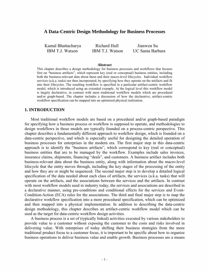
Figure 1: Three Logical Levels of BPM
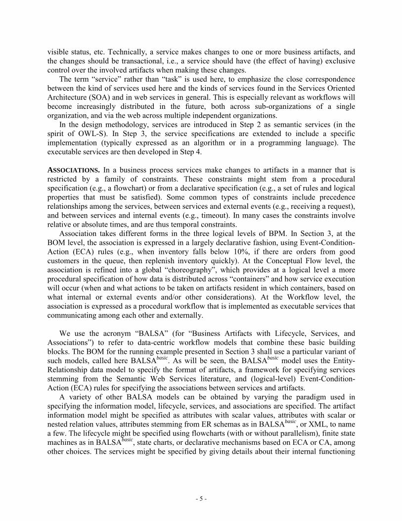
2, the methodology is outlined in brief. Section 3 demonstrates the key design steps and techniques of this methodology using an example application. Section 4 briefly discusses the benefits of using a data-centric methodology and workflow model. Section 5 offers a summary and conclusions. 2. THE DATA-CENTRIC DESIGN METHODOLOGY This section provides an overview of the data-centric design methodology. This methodology is based on a three-level framework, which is provides the structure for how high-level declarative business process models can be mapped faithfully into implemented, procedural workflows. In Section 2.1, a rich family of possible artifact-centric workflow models is described. In Section 2.2, the design methodology itself is outlined. At the core of the data-centric design methodology is a three-level framework for business processes (Figure 1). At the top level, a Business Operations Model (BOM) provides a detailed logical specification of business process execution. In the running example used in this chapter, in addition to business artifacts, the BOM includes services specified in terms of their semantics (including pre-conditions and conditional effects), and ECA rules. At the bottom level is the operational workflow system in which executable services communicate with each other through messages and manipulate artifacts. At the middle is the conceptual workflow that captures essentially the BOM in a procedural manner, while hiding implementation details. This level is suitable for optimization since it allows for efficient reasoning in the context of the physical requirements for implementation, including possibly legacy systems and distribution of the workflow across organizations. 2.1. A family of possible artifact-centric business process models There are many ways that the central notion of business artifact can be used as the basis for a workflow model. Although the chapter is focused on a specific artifact-centric workflow model, this section provides a more general overview of possible artifact-centric workflow models. There are four key elements in an artifact-centric workflow model: business artifact information model, business artifact macro-level lifecycle, services (tasks), and the association of services to business artifacts. We use the term ‘association’ here to indicate that the association might be specified in a largely declarative way using rules or a much more procedural manner using a flowchart or conventional workflow model. When it is clear from the context, we sometimes use the term ‘artifact’ to mean ‘business artifact.’ In the following, we give a brief explanation of these four concepts, while noting that the concepts may take different (syntactic and semantic) forms in different steps of design. BUSINESS ARTIFACT INORMATION MODEL. The information model (or database schema) of a
- 4 -
business artifact is intended to hold all of the information needed in completing business process execution in connection with a given business entity. The artifact data should incorporate the information needed to (i) capture business process goals, and (ii) allow for evaluating how thoroughly these goals are achieved. Example data found in artifacts include data that are received during the business process execution from the external world, data that are produced by the execution, and data that record the decisions taken in the execution. A business artifact has an identity and can be tracked as it progresses through the workflow. It can have a set of attributes to store the data needed for the workflow execution; in the general setting, both attributes and their values can be created, updated, or deleted by the services in the workflow. The attributes may be simple scalars or richly nested data structures. A good approach to modeling artifacts is to make them self-contained, in that all data needed by the artifact is present in the artifact. A subtlety arises when one artifact needs to refer to another one. For example, an order artifact typically refers to a customer, which may also be represented by an artifact. While it is appropriate to use the customer ID as a way to refer to a given customer, specific order-relevant data such as the shipping address of the customer, at the time the order was made, should be stored (either physically or virtually) as a part of the order. In business terms, an artifact represents the explicit knowledge concerning progress toward a business operational goal at any instant. Operational goals, such as processing a customer order, are measurable results that individually and in the aggregate satisfy the purpose of the business. The information contained in the set of artifacts records all the information about the business operation. Hence, at any time of execution, the “runtime state” of a business process is determined by the snapshot of all artifacts. BUSINESS ARTIFACT (MACRO-LEVEL) LIFECYCLE. In the data-centric methodology, business artifacts combine, at a fundamental level, the information model for key business entities along with their macro-level lifecycle. In most cases the business stakeholders can describe this macro-level lifecycle in terms of stages in the possible evolution of the artifact, from inception to final disposition and archiving. In the artifact-centric workflow model presented in Section 3, the macro-level lifecycle of a given class of artifacts is represented using a variant of finite state machines, where each state of the machine corresponds to a possible stage in the life-cycle of an artifact from this class. In this variant of state machines, little or nothing is indicated about why or how an artifact might move from one stage to another, although conditions may be attached to transitions in the machine. Artifacts may have differing “life expectancies.” In some cases the artifact is relatively short-lived (e.g., a customer order), in other cases relatively long-lived (e.g., a customer, including an ongoing log of services to a customer, their preference level for the enterprise, their perceived level of satisfaction), and in yet other cases the artifact is essentially permanent (e.g., an artifact which holds the information about a product type, including product description, availability, and purchasing trends). SERVICES. A service in an artifact-centric business process encapsulates a unit of work meaningful to the whole business process in at least two aspects. First, the potential changes made by the service should reflect a measurable step (or steps) of progress towards the business goal. Second, the division of the business process into some collection of services should be able to accommodate (expected) administrative organization structures, IT infrastructures, customer-
- 5 -
visible status, etc. Technically, a service makes changes to one or more business artifacts, and the changes should be transactional, i.e., a service should have (the effect of having) exclusive control over the involved artifacts when making these changes. The term “service” rather than “task” is used here, to emphasize the close correspondence between the kind of services used here and the kinds of services found in the Services Oriented Architecture (SOA) and in web services in general. This is especially relevant as workflows will become increasingly distributed in the future, both across sub-organizations of a single organization, and via the web across multiple independent organizations. In the design methodology, services are introduced in Step 2 as semantic services (in the spirit of OWL-S). In Step 3, the service specifications are extended to include a specific implementation (typically expressed as an algorithm or in a programming language). The executable services are then developed in Step 4. ASSOCIATIONS. In a business process services make changes to artifacts in a manner that is restricted by a family of constraints. These constraints might stem from a procedural specification (e.g., a flowchart) or from a declarative specification (e.g., a set of rules and logical properties that must be satisfied). Some common types of constraints include precedence relationships among the services, between services and external events (e.g., receiving a request), and between services and internal events (e.g., timeout). In many cases the constraints involve relative or absolute times, and are thus temporal constraints. Association takes different forms in the three logical levels of BPM. In Section 3, at the BOM level, the association is expressed in a largely declarative fashion, using Event-Condition-Action (ECA) rules (e.g., when inventory falls below 10%, if there are orders from good customers in the queue, then replenish inventory quickly). At the Conceptual Flow level, the association is refined into a global “choreography”, which provides at a logical level a more procedural specification of how data is distributed across “containers” and how service execution will occur (when and what actions to be taken on artifacts resident in which containers, based on what internal or external events and/or other considerations). At the Workflow level, the association is expressed as a procedural workflow that is implemented as executable services that communicating among each other and externally. We use the acronym “BALSA” (for “Business Artifacts with Lifecycle, Services, and Associations”) to refer to data-centric workflow models that combine these basic building blocks. The BOM for the running example presented in Section 3 shall use a particular variant of such models, called here BALSAbasic. As will be seen, the BALSAbasic model uses the Entity-Relationship data model to specify the format of artifacts, a framework for specifying services stemming from the Semantic Web Services literature, and (logical-level) Event-Condition-Action (ECA) rules for specifying the associations between services and artifacts. A variety of other BALSA models can be obtained by varying the paradigm used in specifying the information model, lifecycle, services, and associations are specified. The artifact information model might be specified as attributes with scalar values, attributes with scalar or nested relation values, attributes stemming from ER schemas as in BALSAbasic, or XML, to name a few. The lifecycle might be specified using flowcharts (with or without parallelism), finite state machines as in BALSAbasic, state charts, or declarative mechanisms based on ECA or CA, among other choices. The services might be specified by giving details about their internal functioning
- 6 -
(e.g., using flowcharts, state machines, BPEL), or in a more black-box manner by specifying only their I/O properties, or in a gray-box manner―as in BALSAbasic―using I/O and also pre- and post-conditions, among other possibilities. There is a fuzzy boundary between the paradigm used for specifying lifecycles and the paradigm used for specifying associations. For example, generalization of BALSAbasic could be obtained by using ECA rules to specify the lifecycles, and letting the designer decide whether to use a state machine paradigm or something else for lifecycle of artifacts in a particular BOM. Further, the distinction between lifecycle and association is fuzzy―in some variations of BALSA the lifecycle might be extremely detailed, in essence encompassing all aspects of the association level. The choice among the different paradigms in constructing a BALSA workflow model will depend on the intended areas of application.
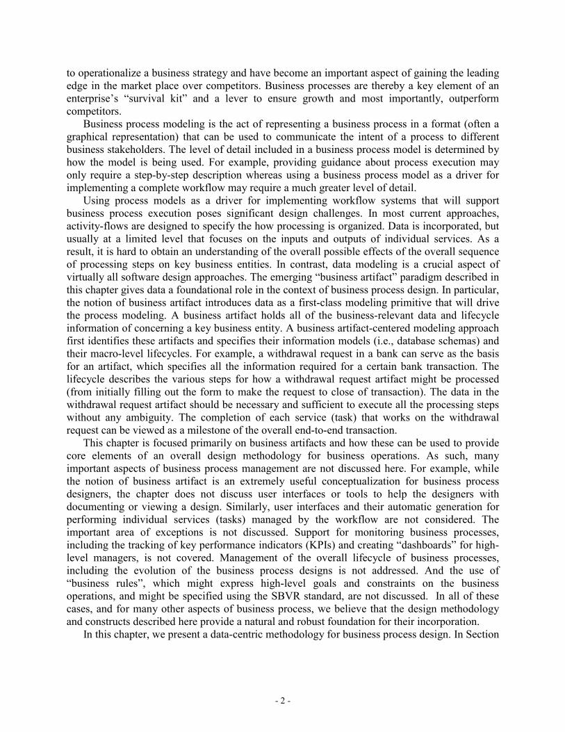
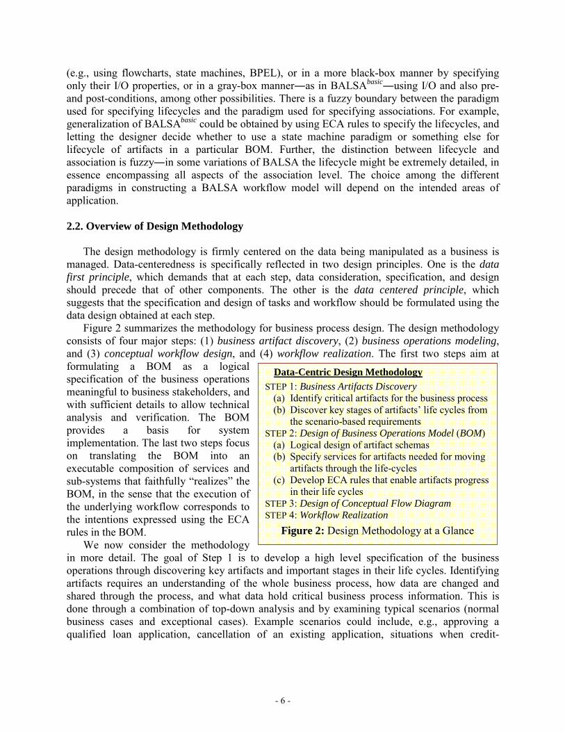
2.2. Overview of Design Methodology The design methodology is firmly centered on the data being manipulated as a business is managed. Data-centeredness is specifically reflected in two design principles. One is the data first principle, which demands that at each step, data consideration, specification, and design should precede that of other components. The other is the data centered principle, which suggests that the specification and design of tasks and workflow should be formulated using the data design obtained at each step. Figure 2 summarizes the methodology for business process design. The design methodology consists of four major steps: (1) business artifact discovery, (2) business operations modeling, and (3) conceptual workflow design, and (4) workflow realization. The first two steps aim at formulating a BOM as a logical specification of the business operations meaningful to business stakeholders, and with sufficient details to allow technical analysis and verification. The BOM provides a basis for system implementation. The last two steps focus on translating the BOM into an executable composition of services and sub-systems that faithfully “realizes” the BOM, in the sense that the execution of the underlying workflow corresponds to the intentions expressed using the ECA rules in the BOM. We now consider the methodology in more detail. The goal of Step 1 is to develop a high level specification of the business operations through discovering key artifacts and important stages in their life cycles. Identifying artifacts requires an understanding of the whole business process, how data are changed and shared through the process, and what data hold critical business process information. This is done through a combination of top-down analysis and by examining typical scenarios (normal business cases and exceptional cases). Example scenarios could include, e.g., approving a qualified loan application, cancellation of an existing application, situations when credit-
Data-Centric Design Methodology STEP 1: Business Artifacts Discovery
(a) Identify critical artifacts for the business process (b) Discover key stages of artifacts’ life cycles from
the scenario-based requirements STEP 2: Design of Business Operations Model (BOM)
(a) Logical design of artifact schemas (b) Specify services for artifacts needed for moving
artifacts through the life-cycles (c) Develop ECA rules that enable artifacts progress
in their life cycles STEP 3: Design of Conceptual Flow Diagram STEP 4: Workflow Realization
Figure 2: Design Methodology at a Glance
- 7 -
checking is unnecessary. A scenario does not have to be complete. Scenarios are useful as they are concrete examples of what should happen under some circumstance and how. Step 1(b) is to discover and develop scenarios. Based on the top-down analysis and scenarios, in Step 1(b) important business stages are formulated and then the processing constraints on artifacts from the scenarios are synthesized to form an artifact life cycle representing possible ways for artifacts to complete in the business process. One possible form of representing an artifact life cycle is a directed graph with nodes representing stages and edges reflecting the sequencing requirements. Each graph defines a life cycle state machine. It is interesting to note that the machine is in many cases an abstraction of business processes in which hardcopy documents move between places. In Step 2, the preliminary design produced in Step 1 provides the basic skeleton around which the BOM can be constructed. In particular, Step 2(a) focuses on data design of artifacts; in particular, the details of the artifact schemas are specified using ER diagrams, which provide a natural framework for specifying these designs at an appropriate level of detail. In Step 2(b), the business activities are examined with respect to the logical artifact schemas. Using the life cycle state machines to provide a macro-structure, abstract services are developed for the various business activities which operate on the artifacts. Finally in step 2(c) the associations between the services and the artifacts are specified. Steps 3 and 4 start from the BOM developed in Step 2 with the goal of obtaining an operational workflow system. This chapter is focused on workflow realizations for which there is a lack of central control, with components (artifacts and services) distributed both geographically and administratively. This is motivated by the increasing trend for outsourcing and globalization as enabled by the internet. For this context, a conceptual flow diagram is first developed in Step 3 that describes globally how different data and service components should be coordinated to fulfill the business operational requirements as specified in the BOM. The conceptual flow diagram can be viewed as another variant of the BALSA framework, in which the associations between services and artifacts are procedural in nature. In the methodology, the conceptual flow diagram is further modified to satisfy the service behavioral constraints, and optimized according to performance metrics. In Step 4, individual components as well as the workflow are turned into software systems with less or clear dependency. 3. ILLUSTRATION OF THE DESIGN METHODOLOGY This section will illustrate the key elements of the data-centric design methodology using an example from the IT service provider business, called Distributed Enterprise Services (DES). First the example is described, after which three subsections discuss steps 1, 2, and 3 (respectively) of the data-centric design methodology outlined in Section 2. The DES example focuses on an IT service provider that provides IT services to one or more enterprises, each of which comprise a large number of geographically distributed “small sites”. To avoid confusion, when it is not clear from the context we shall refer to the IT services in the DES example as ‘DES services’, and refer to the services used to manage the business operations of the IT service provider as ‘BOM services’. In the DES example, provided DES services include IT provisioning, installation, and maintenance as well as general support. Typical examples for small sites are individual hotels that are part of a larger chain, or fast food restaurants that are part of a franchise. The IT service
- 8 -
Configuration Artifacts
ExecutionArtifacts
Offered DESService
Generic Task
Schedule (for Offered DES Service)
VendorTask
1
n
1
n
1 n
1 n
Customer
Site
1
n
Background Artifacts
Vendorn m
1 n
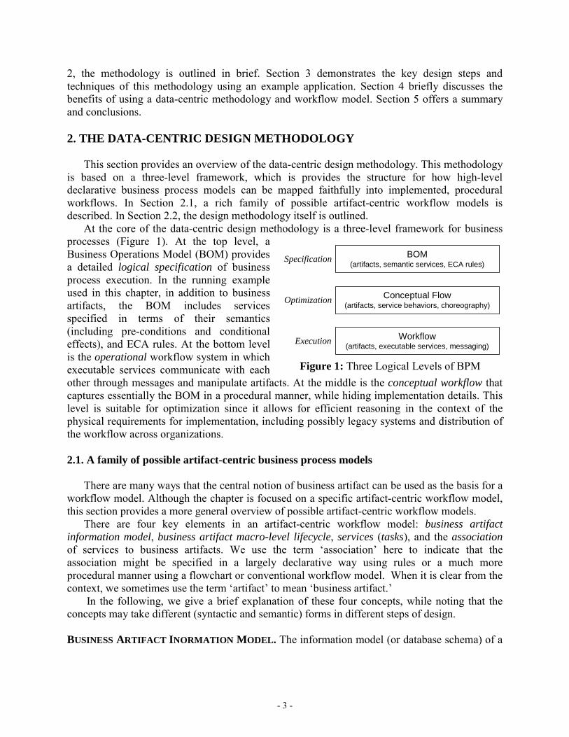
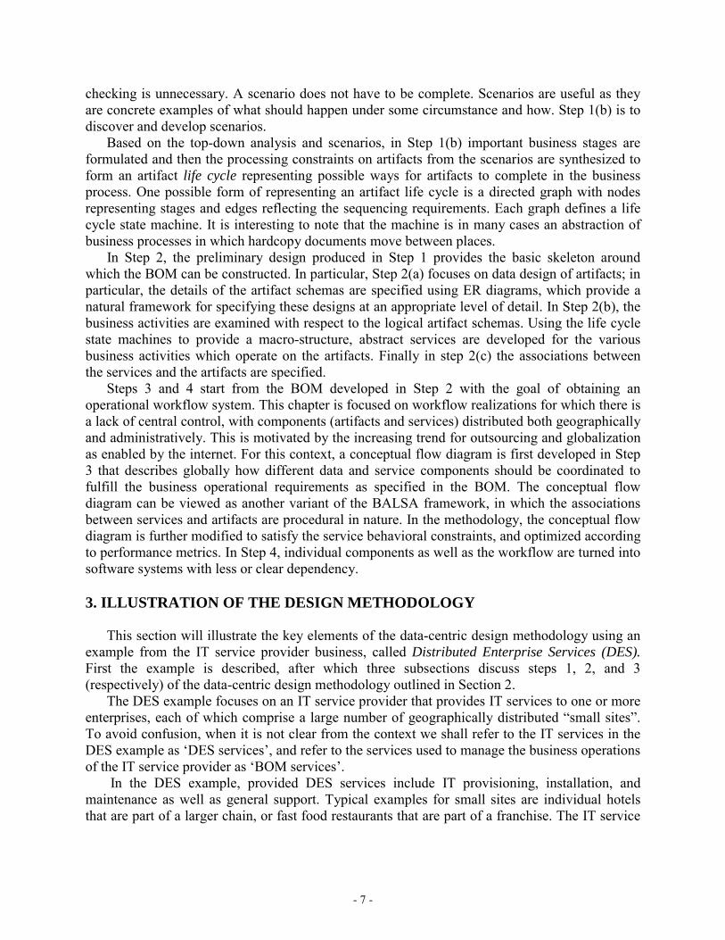
Figure 3: Key artifacts for DES example, and primary relationships between them
provider typically signs a contract with a given chain or franchise corporation, which determines the service level agreements (SLAs) for each request for a given DES service. For example, a hotel corporation might sign a contract with the IT service provider that allows the provider to perform any kind of IT systems-related services at individual hotel sites. The DES services provided at the sites may be performed by the IT service provider themselves or by one or more sub-contracted vendors, the latter being rather typical due to the highly distributed nature of the problem. 3.1. Business Artifact Discovery for DES
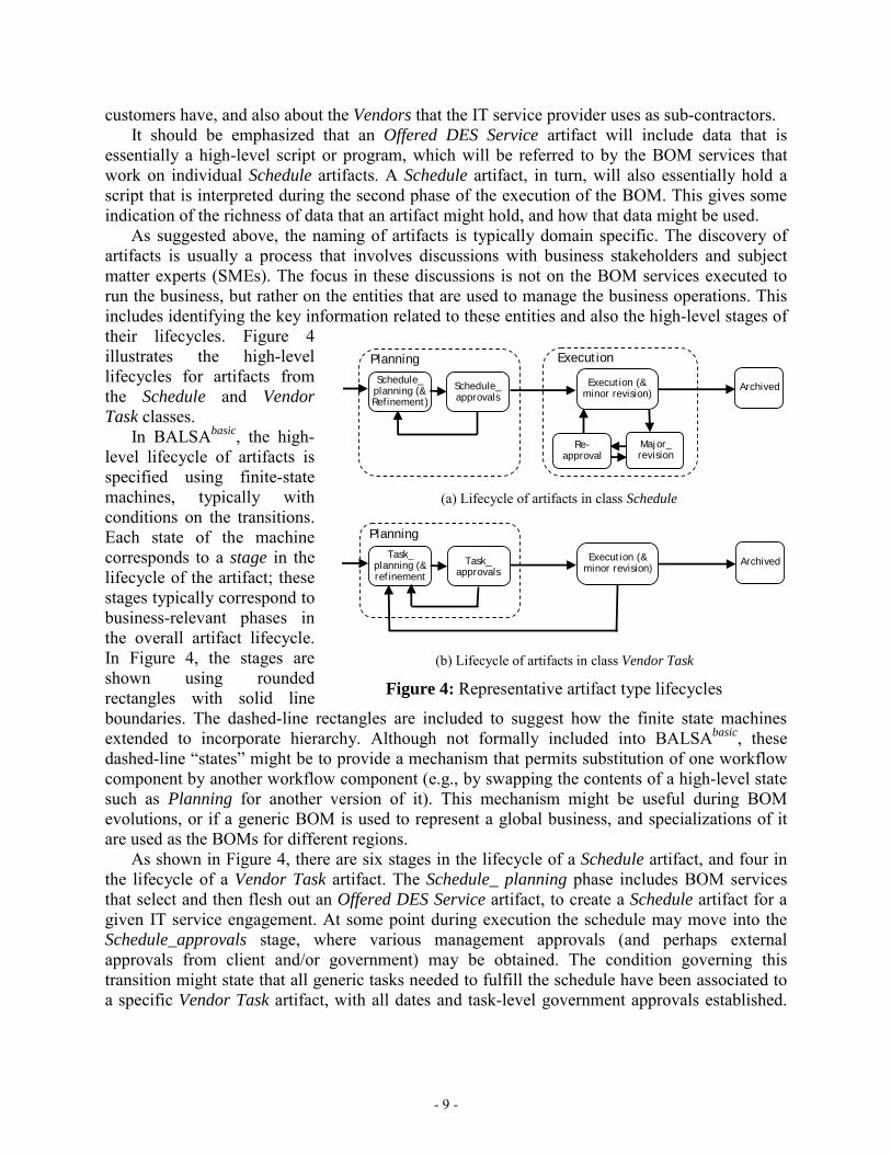
In managing the business operations of an IT service provider of Distributed Enterprise Services, the artifact-centered approach focuses on the key business entities that keep track of how the business (in this case the IT service provider) reaches its operational goals. The first step of the design methodology is to identify, at a high level, these entities, along with the key stages of their life-cycle. The process used is typically a combination of top-down consideration along with scenario-based requirements gathering. Scenarios are often easy for the business stake-holders to create and understand, and should include both “sunny day” and exceptional cases. The main operational goal in DES is the completion of a (possibly complex) DES service or installation at a site. The key kind of artifact that measures progress towards the operation goal for this case is called a Schedule artifact. It contains the planned and actual content of the installation project plan, including any mid-stream modifications to the plan and the working documents transferred between tasks as part of the execution. Note that the term “schedule” for this business case was derived from the fact that an outline project plan is generally attached as a schedule to the contract statement of work (SOW). A second important class of artifacts is called Vendor Task. Each artifact in this class corresponds to an individual (DES) task to be performed, by the IT service provider or one of its sub-contractors, as part of an overall schedule. In general a single Schedule artifact will refer to several Vendor Task artifacts. Figure 3 shows at a high level the key artifacts for the DES example. Shown on the right-hand side are the two artifacts already described, which are used primarily during the “execution” of DES services. In the middle of the diagram are two artifact classes used during the “configuration” or set-up of a DES service. Specifically, the Offered DES Service artifact class holds templates for the different kinds of DES services that can be provided. In general, an actual Schedule artifact will be created by starting with an Offered DES Service artifact and then instantiating various components of it. Similarly, the Generic Task artifact class holds descriptions of (DES) tasks that are available to the IT service provider, including information on the vendors that provide them and the geographic regions for which they are available. Finally, on the left-hand side are some key artifact classes that provide on-going background information, including about the Customers of the IT service provider, along with the Sites that those
- 9 -
ArchivedExecution (& minor revision)
Schedule_ planning (& Refinement)
Schedule_ approvals
ExecutionPlanning
ArchivedExecution (& minor revision)
Task_ planning (& refinement
Task_ approvals
Planning
(a) Lifecycle of artifacts in class Schedule
(b) Lifecycle of artifacts in class Vendor Task
Re-approval
Major_ revision
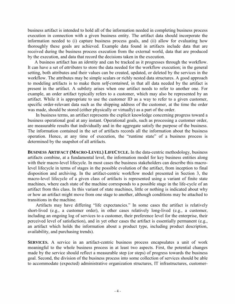
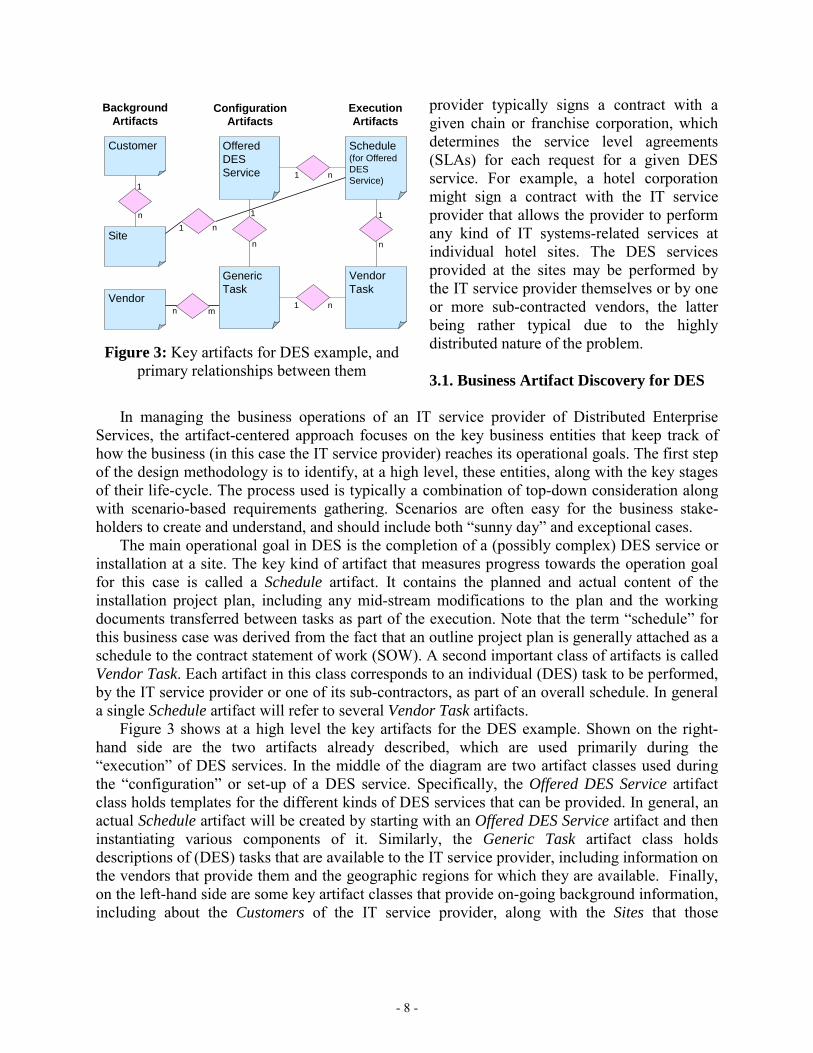
Figure 4: Representative artifact type lifecycles
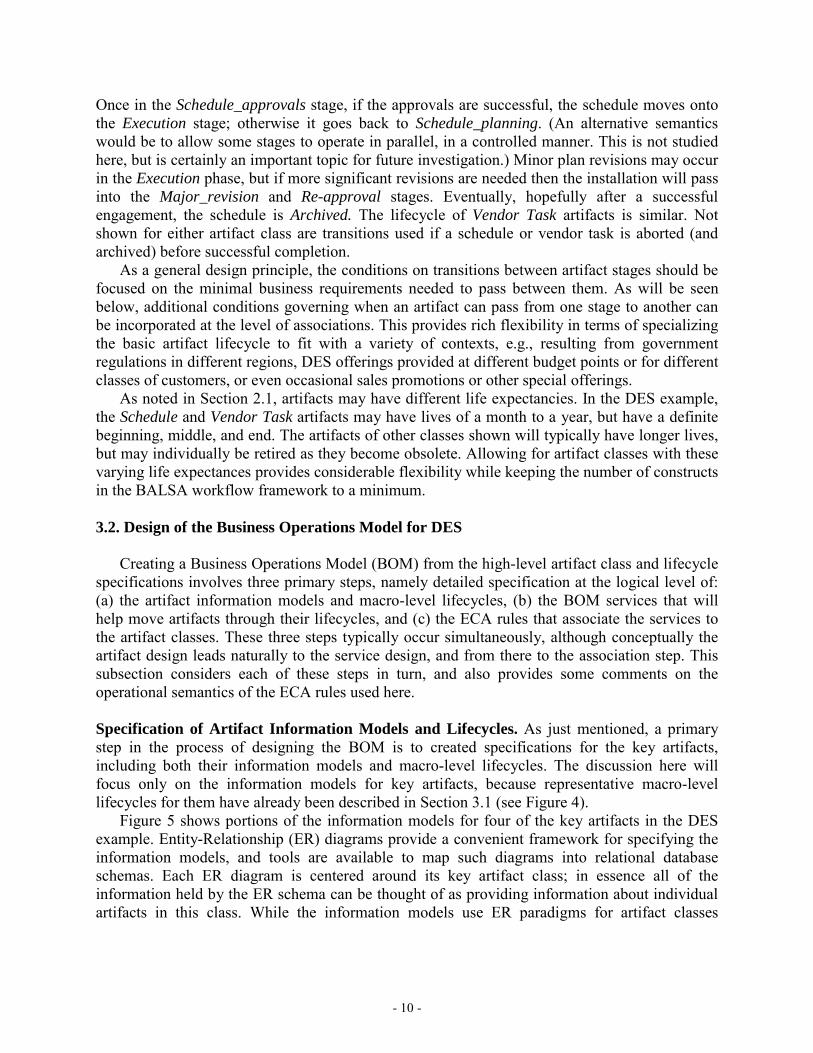
customers have, and also about the Vendors that the IT service provider uses as sub-contractors. It should be emphasized that an Offered DES Service artifact will include data that is essentially a high-level script or program, which will be referred to by the BOM services that work on individual Schedule artifacts. A Schedule artifact, in turn, will also essentially hold a script that is interpreted during the second phase of the execution of the BOM. This gives some indication of the richness of data that an artifact might hold, and how that data might be used. As suggested above, the naming of artifacts is typically domain specific. The discovery of artifacts is usually a process that involves discussions with business stakeholders and subject matter experts (SMEs). The focus in these discussions is not on the BOM services executed to run the business, but rather on the entities that are used to manage the business operations. This includes identifying the key information related to these entities and also the high-level stages of their lifecycles. Figure 4 illustrates the high-level lifecycles for artifacts from the Schedule and Vendor Task classes. In BALSAbasic, the high-level lifecycle of artifacts is specified using finite-state machines, typically with conditions on the transitions. Each state of the machine corresponds to a stage in the lifecycle of the artifact; these stages typically correspond to business-relevant phases in the overall artifact lifecycle. In Figure 4, the stages are shown using rounded rectangles with solid line boundaries. The dashed-line rectangles are included to suggest how the finite state machines extended to incorporate hierarchy. Although not formally included into BALSAbasic, these dashed-line “states” might be to provide a mechanism that permits substitution of one workflow component by another workflow component (e.g., by swapping the contents of a high-level state such as Planning for another version of it). This mechanism might be useful during BOM evolutions, or if a generic BOM is used to represent a global business, and specializations of it are used as the BOMs for different regions. As shown in Figure 4, there are six stages in the lifecycle of a Schedule artifact, and four in the lifecycle of a Vendor Task artifact. The Schedule_ planning phase includes BOM services that select and then flesh out an Offered DES Service artifact, to create a Schedule artifact for a given IT service engagement. At some point during execution the schedule may move into the Schedule_approvals stage, where various management approvals (and perhaps external approvals from client and/or government) may be obtained. The condition governing this transition might state that all generic tasks needed to fulfill the schedule have been associated to a specific Vendor Task artifact, with all dates and task-level government approvals established.
- 10 -
Once in the Schedule_approvals stage, if the approvals are successful, the schedule moves onto the Execution stage; otherwise it goes back to Schedule_planning. (An alternative semantics would be to allow some stages to operate in parallel, in a controlled manner. This is not studied here, but is certainly an important topic for future investigation.) Minor plan revisions may occur in the Execution phase, but if more significant revisions are needed then the installation will pass into the Major_revision and Re-approval stages. Eventually, hopefully after a successful engagement, the schedule is Archived. The lifecycle of Vendor Task artifacts is similar. Not shown for either artifact class are transitions used if a schedule or vendor task is aborted (and archived) before successful completion. As a general design principle, the conditions on transitions between artifact stages should be focused on the minimal business requirements needed to pass between them. As will be seen below, additional conditions governing when an artifact can pass from one stage to another can be incorporated at the level of associations. This provides rich flexibility in terms of specializing the basic artifact lifecycle to fit with a variety of contexts, e.g., resulting from government regulations in different regions, DES offerings provided at different budget points or for different classes of customers, or even occasional sales promotions or other special offerings. As noted in Section 2.1, artifacts may have different life expectancies. In the DES example, the Schedule and Vendor Task artifacts may have lives of a month to a year, but have a definite beginning, middle, and end. The artifacts of other classes shown will typically have longer lives, but may individually be retired as they become obsolete. Allowing for artifact classes with these varying life expectances provides considerable flexibility while keeping the number of constructs in the BALSA workflow framework to a minimum. 3.2. Design of the Business Operations Model for DES Creating a Business Operations Model (BOM) from the high-level artifact class and lifecycle specifications involves three primary steps, namely detailed specification at the logical level of: (a) the artifact information models and macro-level lifecycles, (b) the BOM services that will help move artifacts through their lifecycles, and (c) the ECA rules that associate the services to the artifact classes. These three steps typically occur simultaneously, although conceptually the artifact design leads naturally to the service design, and from there to the association step. This subsection considers each of these steps in turn, and also provides some comments on the operational semantics of the ECA rules used here.
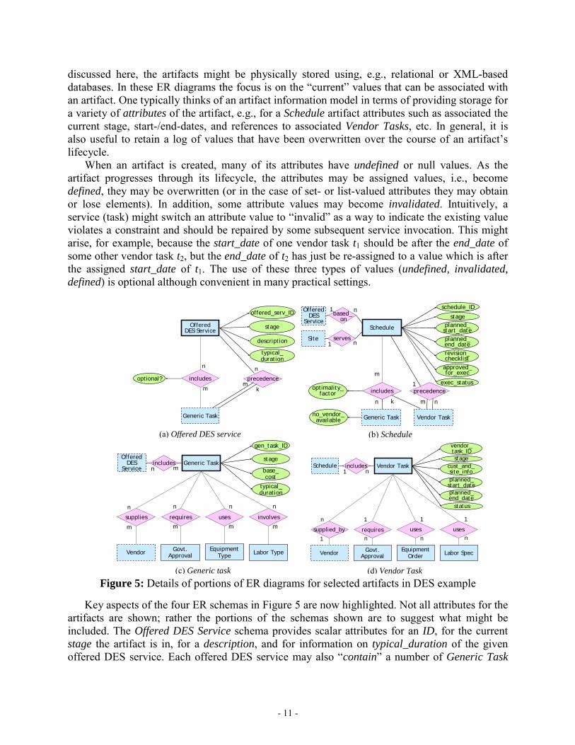
Specification of Artifact Information Models and Lifecycles. As just mentioned, a primary step in the process of designing the BOM is to created specifications for the key artifacts, including both their information models and macro-level lifecycles. The discussion here will focus only on the information models for key artifacts, because representative macro-level lifecycles for them have already been described in Section 3.1 (see Figure 4). Figure 5 shows portions of the information models for four of the key artifacts in the DES example. Entity-Relationship (ER) diagrams provide a convenient framework for specifying the information models, and tools are available to map such diagrams into relational database schemas. Each ER diagram is centered around its key artifact class; in essence all of the information held by the ER schema can be thought of as providing information about individual artifacts in this class. While the information models use ER paradigms for artifact classes
- 11 -
discussed here, the artifacts might be physically stored using, e.g., relational or XML-based databases. In these ER diagrams the focus is on the “current” values that can be associated with an artifact. One typically thinks of an artifact information model in terms of providing storage for a variety of attributes of the artifact, e.g., for a Schedule artifact attributes such as associated the current stage, start-/end-dates, and references to associated Vendor Tasks, etc. In general, it is also useful to retain a log of values that have been overwritten over the course of an artifact’s lifecycle. When an artifact is created, many of its attributes have undefined or null values. As the artifact progresses through its lifecycle, the attributes may be assigned values, i.e., become defined, they may be overwritten (or in the case of set- or list-valued attributes they may obtain or lose elements). In addition, some attribute values may become invalidated. Intuitively, a service (task) might switch an attribute value to “invalid” as a way to indicate the existing value violates a constraint and should be repaired by some subsequent service invocation. This might arise, for example, because the start_date of one vendor task t1 should be after the end_date of some other vendor task t2, but the end_date of t2 has just be re-assigned to a value which is after the assigned start_date of t1. The use of these three types of values (undefined, invalidated, defined) is optional although convenient in many practical settings.
(a) Offered DES service
includes
n
m
OfferedDES Service
Generic Task
precedenceoptional?
offered_serv_ID
description
typical_ duration
n
mk
stage
(b) Schedule
includes
Schedule
Vendor Task
schedule_ID
planned_ start_dateplanned_ end_date
Site serves
Generic Task
optimality_factor
no_vendor_available
exec_status
approved_ for_exec
OfferedDES
Servicebased_
on
revision_ checklist
precedence1
m n
m
n k
1 n
1 n
stage
(c) Generic task
requires
n
m
Generic Task
Govt. Approval
gen_task_ID
Labor TypeEquipmentType
uses involves
n
m
n
m
typical_ duration
base_ cost
supplies
Vendor
n
m
OfferedDES
Serviceincludes
mnstage
(d) Vendor Task
requires
1
n
Vendor Task
Govt. Approval
vendor_task_ID
Labor SpecEquipmentOrder
uses uses
1
n
1
n
planned_ end_date
planned_ start_date
supplied_by
Vendor
n
1
Schedule includes cust_and_site_info
status
1 n
stage
Figure 5: Details of portions of ER diagrams for selected artifacts in DES example
Key aspects of the four ER schemas in Figure 5 are now highlighted. Not all attributes for the artifacts are shown; rather the portions of the schemas shown are to suggest what might be included. The Offered DES Service schema provides scalar attributes for an ID, for the current stage the artifact is in, for a description, and for information on typical_duration of the given offered DES service. Each offered DES service may also “contain” a number of Generic Task
- 12 -
artifacts – these would correspond to the individual tasks that must be performed during the course of the offered service. The rectangle enclosing Generic Task here is shown as dashed, to indicate that this entity type is defined elsewhere (namely in the schema for the Generic Task artifact class). The Boolean attribute optional? can be used to indicate some level of possible variation between instances (i.e., schedules) of an Offered DES Service. Precedence between the generic tasks is also included. For the example described here, a simple notion of precedence is used, based on start- and end-dates of the tasks, but richer forms of precedence could be used. The Schedule schema includes various scalar attributes. The revision_checklist provides a structured value that is used to keep track of the revisions of the schedule that must be performed; this is useful as individual vendor tasks get modified, which may have impact that ripples to other, already planned vendor tasks. A schedule also has specific scalar values for approved_for_exec(ution) and exec(ution)_status, which can be used both to record how an artifact is progressing, and in the events and conditions of ECA rules. The includes relationship is used to connect a schedule to the generic tasks which must be performed, and as the planning process progresses, the specific vendor tasks that will be used to instantiate those generic tasks. The schemas for Generic Task and Vendor Task should be self-explanatory. In those schemas several of the subordinate entity types are shown with solid rectangles, since in this example artifact classes are not associated with them. There are two primary considerations in designing the artifact schemas. The first is driven by the basic axiom of the data-driven approach to workflow, specifically that an artifact A should hold, at any given time, all of the business-relevant information about A. The second consideration is that the logs of artifact instance histories should enable rich and flexible monitoring of current workflow performance, and analysis of past workflow performance. The artifact-centric approach lends itself to this, because the artifact life-cycles typically cross multiple sub-organizations (or organizations, in the case of out-sourcing). Even if the data for an artifact is physically stored in different places, the artifact schemas provide a unifying view against which to define Key Performance Indicators and dashboards, and to perform both systematic and ad hoc data mining and reporting. Although not at the same level as the artifact attributes included into the business operations model, it may be useful to incorporate into the artifact schemas additional attributes to store information about the provenance of the artifacts, that is, how and why they evolved as they did. This could include information about which services were used and details about how and why they were invoked.
Specification of BOM services. The discussion now turns to the second main activity in specifying a BOM: the specification of the BOM services that will help move artifacts through their life-cycles. If the artifact schemas are defined well, it should be relatively straightforward to identify BOM services that correspond to both (a) natural business activities, and (b) update coherent groups of artifacts and attributes. In the discussion here, each BOM service is associated with a primary artifact class; the action of the service will be focused on a single artifact of this class (including possibly creation of a new artifact of this class), and the service might read or write attributes of other artifacts (from the same and/or other artifact classes).
Recall that in the BALSAbasic workflow model, the family of BOM services for an application domain is typically specified in a manner largely independent of the anticipated sequencing of those services. In general, one might have a large library, or “soup”, of BOM services associated with a family of artifact class schemas. For different realizations of an
- 13 -
application domain (e.g., for different IT service providers offering DES) one might associate different subsets of this library to the artifact classes. This permits considerably more flexibility than is typical in workflow frameworks that specify the sequencing of services using exclusively procedural and/or graph-based formalisms. To illustrate key points about BOM services and their specification the Schedule and Vendor Task classes are used. In the DES example there could be over 50 BOM services centered around the processing of artifacts in these classes. The focus here is on the group of BOM services that are relevant when a schedule is in the Schedule_planning stage (although some of them might also be used in the Execution and Major_revisions stages). A small but representative subset of these BOM services is listed below. create_schedule (Offered DES Service: o, Customer: c, Site: si): This service has the effect of
creating a schedule artifact for o, c, and si (where si is a site of c). create_vendor_task (Schedule: sch, Generic Task: g): This service has the effect of creating a
vendor task artifact that will be associated with g in sch. adjust_task_general (Vendor task: t, Vender: v, Schedule: sch, list[Task, start_date,
end_date]): This service is used to revise any and all aspects of a vendor task t during the Task_planning stage. The vendor task serves as the primary artifact for this service and the following ones; the other artifacts that are used as input are all reachable from the primary artifact. The list of tasks with start- and end-dates is intended to hold all tasks that are immediate successors of t according to sch.
adjust_task_date (Vendor task: t, Vender: v, Schedule: sch, list[Task, start_date, end_date]): This service is used to revise the date-related attributes of vendor task t (and possibly touch other artifacts that are impacted, e.g., by invalidating attributes of dependent vendor tasks and updating the revision_checklist attribute of the schedule sch that t belongs to). This service and the next two, while somewhat redundant with adjust_task_general, are included to illustrate how services might overlap in their function. Also, these three services might be executed in parallel, whereas if adjust_task_general is working on a vendor task t, it will typically block the other services from manipulating t.
request_govt_approval (Vendor task: t, Vender: v, Schedule: sch): This service is used to create and transmit a request for one or several government approvals for a vendor task.
adjust_task_govt (Vendor task: t, Vender: v, Schedule: sch, list[Task, start_date, end_date]): This service is used for manipulation of a task when information is received about pending government approvals.
In the BALSAbasic workflow model, at the level of the Business Operations Model, BOM services are specified using four key properties, namely,
• Input artifacts and attributes, • Output artifacts and attributes, • Pre-conditions, and • (Conditional) Effects.
These combine to form the IOPE (pronounced I-O-P-E) specification of the service. The focus here on the logical properties of a service allows for a significant separation of concerns―at the BOM level the focus is on the logical properties and effects of invoking a service, whereas at the Realization level the focus can be on the more procedural and implementation aspects of a
- 14 -
service. This follows the spirit of research in the past few years on OWL-S and more generally, Semantic Web Services. It allows for rich forms of automation in the specification and realization of workflows. For example, synthesis algorithms have been developed for specialized settings, to automatically create compositions of services that satisfy high-level business goals (expressed using logical formulas) and government regulations (also expressed as logical formulas). Also, analysis algorithms, which can verify properties of workflows such as reachability or constraint satisfaction, are sometimes developed more easily if services and other components are specified using high-level logical properties rather than lower-level procedural ones. The use of logical specification of BOM services can also be viewed as providing a partition of specification information: analysis of a BOM at the macro level uses the logical specification of the BOM services, and then analysis of individual BOM services to check whether their detailed specification complies with the IOPE specification can occur separately. In an IOPE specification of a BOM service, the input and output artifacts and attributes identify, respectively, the data values that will be read and that may be updated by the service. The pre-conditions must be satisfied before the service can be invoked. As a design guideline it is generally recommended to keep the pre-conditions as minimal as possible, focusing primarily on conditions needed by the service in connection with the specific artifacts. Additional information about when the service can be applied, which is specific to a given BOM design context, may be incorporated by the ECA rules for that domain. Finally, the conditional effects provide information about the possible effects that applying the service will have. The IOPE specifications are now described for two of the BOM services, namely, create_schedule and adjust_vendor_task. The descriptions are provided in English, although in practice a formal notation would be used. The create_schedule service has an IOPE specification with the following properties.
• Inputs: o An Offered DES Service artifact o, and specifically the listing of used Generic Tasks,
along with whether they are optional, and information about the Precedence relationships between them.
o A Customer artifact c, and specifically information about specific requirements for c, e.g., levels of quality and service to be followed; implications around government regulations; etc.
o A Site artifact si for c, and specifically information about specific requirements for si, including government-related issues based on location, municipality, state; information useful in determining vendor availability, shipping costs, etc.
• Outputs: o A new Schedule artifact sch. The data written will include attributes schedule_ID,
stage, planned_start_date, and the Generic Task portion of the includes relationship. (The concrete Vendor Task values will be filled in by executions of the assign_vendor_task service.)
o The Site artifact si is updated to record the fact that a new Schedule artifact has been created for si.
• Pre-conditions o Offered DES Service artifact o must be compatible with the infrastructure and needs of
site si.
- 15 -
• Conditional effect o If true, then sch is in stage Schedule_planning. o If true, then sch holds a schedule skeleton (i.e., appropriate portions of the relationship
includes are filled in). o If true, the Site artifact si is updated to reflect the creation of sch. o If true, then for each Generic Task artifact g that is required to accomplish o for si for
which there is not at least one qualified Vendor serving the region of the Site, then the no_available_vendor flag is set for g.
The IOPE specification for adjust_task_dates has the following properties:
• Inputs: o A Vendor Task artifact t, information about specific requirements for the customer and
site associated with t’s schedule, and about the current status of various steps (government approvals, equipment availability, etc.).
o A Vendor artifact v, and specifically information about v’s availability, about the cost for re-scheduling the task, etc., for the vendor assigned to perform t.
o A Schedule artifact sch, and specifically information about immediate predecessors and successors of t in sch.
o A list T of triples of form (Task, date, date). • Outputs: o Updates to start and/or end dates of t. o (Possibly) updates to the revision_checklist of sch. o (Possibly) updates to the status fields of each Vendor Task artifact t′ that is a successor
of t in sch, if the modification to t impacts t′, and invalidating the dates of each such artifact.
• Pre-condition o Vendor task t is assigned to supplier v. o Vendor task t occurs in Schedule sch. o T is the list of tuples (t′, st′, et′), where t′ is a task that succeeds t in sch according to the
Precedence relationship, and st′, et′ are the start- and end-times of t′, respectively. • Conditional effects o If true, then the start and/or end dates of t may have been overwritten o If the start date of t is overwritten, then it is after the end date of each predecessor of t. o If the start or end date of t is overwritten and this impacts the timing of any successor t′
of t (i.e., any task occurring in T), then the dates for t′ are invalidated and the revision_checklist of sch is updated accordingly.
There is a circumscription condition on the semantics associated with conditional effects. Specifically, in the application of a BOM service each attribute that is not mentioned in the consequent part of a conditional effect with condition that evaluates to true must not change its value, and likewise, the state of an artifact must not change unless that is specifically called for by a conditional effect with condition that evaluates to true. One might expect that the adjust_task_dates should include in the pre-condition a restriction permitting the service to run only if a vendor task’s schedule is in stage schedule_planning,
- 16 -
execution, or major_revision, since those are the stages where schedules might be modified. However, in the overall design of the BOM presented here, this restriction is incorporated into the ECA rule that governs when adjust_task_dates can be invoked. In general, there are trade-offs concerning whether conditions are included into the pre-condition for a service or the ECA rules that govern when it can be invoked. One advantage of keeping a service’s pre-condition minimal is that it allows the service to be used in a broader variety of application domains and contexts.
Specification of ECA rules. The discussion now turns to the third major phase of specifying a BOM in BALSAbasic, namely, the specification of how services are associated to artifacts, or in other words, the specification of the “micro-level” of artifact lifecycles. The model uses Event-Condition-Action (ECA) rules. In general these rules have the form “if some event occurs, and if a condition is true about the objects that witness the event occurrence, then take a particular action.” In some cases there are also “CA” rules in which the event portion is not specified; this means that the rule can be applied at essentially any time. The ECA rules used in BALSAbasic are focused at the conceptual level of the model; in particular the events are specified in terms of the BOM services being invoked or terminating; artifacts being created or modified, or changing stage; and operations-level external messages being received into the workflow system. The ECA paradigm has been used in workflow (and other) contexts for several decades, and provides a very flexible mechanism for specifying system behaviors. On the one hand, it can be used to faithfully simulate flow-charts and other highly procedural styles of behavior specification. At the other extreme, by exclusively using CA rules the paradigm can take on a very declarative style reminiscent of logic programming and deductive database systems. Between these extremes, ECA can be used to simulate the paradigms of expert systems and production rule systems. Different “macros” can be constructed on top of an ECA basis to make it easy for ruleset creators and business users to think in terms of the various paradigms just mentioned. Further, a “hybrid” framework can be constructed on top of the ECA basis, combining for example a flowchart specification for certain stages of an artifact class and a much more free-form, declarative specification for some other stages of the class. BALSAbasic focuses on ECA because it provides a minimal set of constructs that can form the basis for this rich family of variations for associating services to artifacts in the data-centric workflow setting. In the example ECA rules presented here, a fourth field is included. This “By” field is used to list the properties and qualifications of the people who may perform the associated action. These “performers” might include customer service representatives, clerks, managers, etc. This field is included here primarily to provide a brief illustration of how information about the process users and their participation can be associated to artifact lifecycles. In a full solution, it will be useful to include a substantial meta-model for representing all of the people that might be involved with a BOM, and the ways that they might interact with it. In addition to the actual performers, it will be useful to model teams of users, experts that provide consulting advice to the people actually performing the BOM services, etc. The basic building blocks for the ECA rules used here are as follows.
Events:
• An attribute value just assigned • An attribute value just assigned and satisfies a predicate involving other current artifacts
- 17 -
and attribute values • An artifact has just moved into a stage • A service has been launched or completed on an artifact • An incoming message (e.g., from a government agency) • A performer request
Conditions
• Formulas written in first-order logic (or, more-or-less equivalently, a relational database query language). Typically the conditions come from a targeted subset of first-order logic, such as the quantifier-free fragment, or the fragment which does not permit quantifier alternations.
Actions
• Invoke a service • Move an artifact to a stage
By
• Roles and qualifications needed by the performer of the action A small family of representative ECA rules for the DES example is now presented, followed by a discussion of the semantics associated with ECA rules.
R1: Initiate schedule
event request by performer p to create a schedule instance for Offered DES Service artifact o, Customer artifact c, and Site artifact si
condition the appropriate non-disclosure agreements (NDAs) are in place for c action invoke create_schedule(o, c, si) by performer p where offer_manager in role(p) and qualification(p, o, region:
si.region) ≥ 5
The above rule is used to create a new schedule. It is triggered when a performer requests this. Note that the request includes the offered DES service, the customer, and the customer site where the service will be given. The qualification function is used in this rule and below as a mechanism for indicating the skill set needed by the performer that will actually perform the service being invoked. For these examples the values of qualification range from 1 (not very qualified) to 10 (a guru). The input argument si.region illustrates how we use the “.” notation to navigate through one or more artifacts to find values of interest. This in-place function is viewed as being polymorphic–depending on the number and types of the input arguments it will evaluate appropriately. This function could be supported by a family of relational database tables.
R2: Initiate vendor task
condition for Schedule artifact sch and Generic task artifact g contained in sch, each predecessor of g in sch has an associated vendor task artifact with defined start and end dates; sch is in stage Schedule_planning or Major_revision; and g does not have an associated vendor task.
- 18 -
action invoke create_vendor_task(s,g) by performer p where qualification(p, sch.offered_service, g) ≥ 2 and
qualification(p, g, sch.customer.site.region) ≥ 6.
Note that this rule has no triggering event, which means that the rule can be fired at essentially any time that the condition becomes true. In practice, the rule might be triggered when the final predecessor of g in sch obtains defined start- and end-dates. In the example, the create_vendor_task will, among other things, set the intended start and end dates for the created vendor task. This is why the predecessor tasks of g in sch must already have dates assigned. Here the performer must be somewhat knowledgeable about the overall offered DES service that underlies schedule sch, and also well-qualified on the generic task g for the region where sch will be installed. There may be other rules that enable invocation of create_vendor_task, e.g., if a performer requests it.
R3: Adjust vendor task dates
condition for Vendor Task artifact t occurring in Schedule artifact sch, sch is in stage Schedule_planning, Execution or Major_revision; the start- and/or end-date of t is invalid; and each predecessor of t in schedule sch (according to the precedence relationship in sch) has defined start and end dates.
action invoke adjust_task_dates(t, v, sch, T), where v is the vendor supplying t, and T is a list of triples holding, for each task t’ that succeeds t in sch, the triple (t’, s, e) where s, e are the start- and end-times of t’, respectively.
by performer p where qualification(p, o, g) ≥ 4, where o is the offered DES service associated with sch, and qualification(p, g, region: sch.customer.site.region) ≥ 8.
Performing the service adjust_task_dates under this rule requires more qualifications than performing create_vendor_task. This rule can be fired whenever the dates of a vendor task are invalid.
R4: Request task government approval condition for Vendor task artifact t occurring in schedule sch, sch is in stage
Schedule_approvals or Re_approval; if government approval is needed for t and not yet requested; and the required values for t are defined.
action invoke request_govt_approval(t, v, sch), where v is the vendor providing t. by performer p where qualification(p, sch.offered_service, g) ≥ 2 and
qualification(p, g, t.schedule.customer.site.region, aspect: “government”) ≥ 6.
R5: Modify task government information
event receive government response to a request approval of Vendor task artifact t which is owned by schedule sch.
condition sch is in stage Schedule_approvals or Re_approval. action invoke adjust_task_govt(t, v, sch, T), where v is the vendor supplying t,
sch is the schedule that t participates in, and T is a list of triples holding,
- 19 -
for each task t′ that succeeds t in sch, the triple (t′, s, e) where s, e are the start- and end-times of t′, respectively.
by performer p where qualification(p, sch.offered_service, g) ≥ 2 and and qualification(p, g, region: t.schedule.customer.site.region, aspect: “government”) ≥ 6.
The above two rules focus on government approvals for vendor tasks.
R6: Launch schedule approval condition for Schedule artifact sch, sch is in stage Schedule_planning;
sch.revision_checklist is empty; and for each Generic task artifact g of sch, g has an associated Vendor task artifact t which has t.status = ready_for_execution.
action move_to(sch, Schedule_approvals) by automatic
The above rule permits a schedule to move from the Schedule_planning stage to the Schedule_approvals stage. This illustrates how the set of ECA rules associated with an application domain can specialize the conditions about stage transitions that are incorporated into the finite state machine for the macro-level life-cycle of an artifact. Note the use of a universal quantification (“for each Generic task artifact g …), which in this case is “bounded” to range over artifacts associated with sch.
R7: Launch schedule execution
event for Schedule artifact sch, sch.approved_for_exec := true condition true action move_to(sch, Execution) by automatic
The final example rule permits a schedule to move to the Execution stage. This is triggered when the attribute approved_for_exec is set to true. This illustrates that there can be a close relationship between attribute values and stages in the macro-level lifecycle. Indeed, in a formal sense the state machine for stages can be simulated by extra attributes and some ECA rules. However, the stages and state machine are explicitly incorporated into the model to make BALSAbasic BOMs more readily understood by business managers, and to permit the specification of an intuitive structure for lifecycles at the macro level.
Execution Semantics of ECA rules. A simple, representative, logical execution semantics for ECA-based rules is now described. We emphasize that these are at the logical rather than implementation level – many optimizations can be incorporated when implementing a given ruleset while nevertheless obeying the logical semantics. The logical semantics is based on the following concepts. 1) Non-determinism: In the semantics presented here, non-determinism is permitted in two ways. The first concerns the order that eligible rules are fired. Thus, if more then one rule is
- 20 -
triggered by the same event, or more generally, if more than one rule is eligible for firing at a given point, then the system will pick one of them non-deterministically for execution. This kind of assumption is common in declarative frameworks; once a designer is used to the non-determinism it can provide more flexibility in the design of an ECA ruleset. Alternatively, an ECA ruleset might incorporate mechanisms that restrict the non-determinism by requiring that rules happen in a more deterministic fashion (e.g., by adding conditions that help to narrow the set of rules eligible at any given point in time). The non-determinism offers many opportunities for optimization in the implementation. Importantly, an implementation that enables any one of the non-deterministically specified executions of the ECA ruleset is considered to be valid; the implementation does not itself have to support the non-determinism nor enable all possible valid execution sequences. The assumption of non-determinism is also quite useful in connection with formal verification and automated construction of ECA rulesets. The second form of non-determinism is discussed in item (3) below. 2) Rule triggering: This applies to rules with explicitly specified event. Such a rule is triggered if the event becomes true for some particular binding (assignment) β of the variables occurring in the event. The rule can be triggered only once for a given event and binding. 3) Rule firing: A rule is considered to be eligible for a given variable binding β if its event has been triggered with binding β, or if it has no event (in which case β is empty). The rule firing for an eligible rule has two phases. First, the condition of the rule is tested. The condition is considered to be true if there is some binding β’ which extends β to the unbound variables occurring in the condition, so that the condition is true under β’. This choice of β’ is the second form of non-determinism in the logical semantics for ECA ruleset execution. For a given eligible rule only one of the bindings β’ that makes the condition true is considered when firing the rule. If an appropriate performer is not available to perform the action, then the action is parked until a performer becomes available. 4) Heap of eligible rules: As suggested in point (1) above, an unordered heap is maintained that holds eligible rules. Each time a rule event for some binding, the rule with binding is placed on the heap. Also, whenever a rule without event has a binding for which the condition is true, it is put on the heap with that binding. At any point in time a rule with binding in the heap can be selected and fired. 5) No starvation: The actual processing of the rules cannot indefinitely “starve” an eligible rule from firing. 6) Serializability: While the actual processing of the rules and their action might be interleaved and/or parallel, the net effect of the firing of rules must be equivalent to some serial firing of the rules with the same bindings. (This is analogous to the serializability requirement typically placed on sets of updates to a database.) With any ECA-based semantics there are several issues that must be considered. At the logical level, these include the following. Reachability: Given a set of rules, is a given predicate (e.g., a certain stage in the macro
lifecycle, an attribute reaching a given value, etc.) reachable through firings of the rules? Deadlock: Can the system reach a deadlock? How can all deadlocks be prevented? Termination: For each artifact type with a bounded lifecycle, does each execution of the
rules for artifacts of this type end in a finite number of steps?
- 21 -
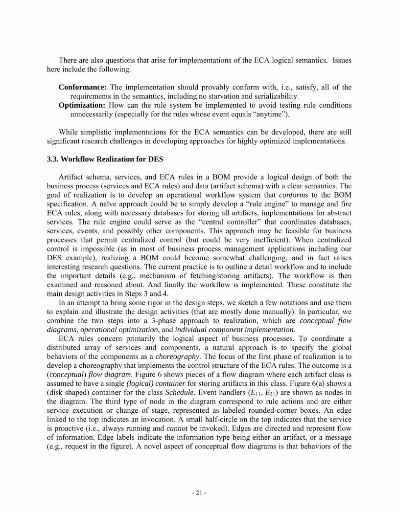
There are also questions that arise for implementations of the ECA logical semantics. Issues here include the following.
Conformance: The implementation should provably conform with, i.e., satisfy, all of the
requirements in the semantics, including no starvation and serializability. Optimization: How can the rule system be implemented to avoid testing rule conditions
unnecessarily (especially for the rules whose event equals “anytime”).
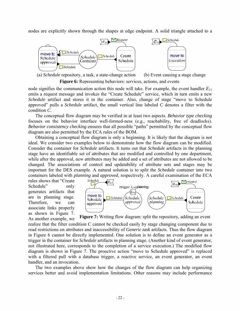
While simplistic implementations for the ECA semantics can be developed, there are still significant research challenges in developing approaches for highly optimized implementations. 3.3. Workflow Realization for DES Artifact schema, services, and ECA rules in a BOM provide a logical design of both the business process (services and ECA rules) and data (artifact schema) with a clear semantics. The goal of realization is to develop an operational workflow system that conforms to the BOM specification. A naïve approach could be to simply develop a “rule engine” to manage and fire ECA rules, along with necessary databases for storing all artifacts, implementations for abstract services. The rule engine could serve as the “central controller” that coordinates databases, services, events, and possibly other components. This approach may be feasible for business processes that permit centralized control (but could be very inefficient). When centralized control is impossible (as in most of business process management applications including our DES example), realizing a BOM could become somewhat challenging, and in fact raises interesting research questions. The current practice is to outline a detail workflow and to include the important details (e.g., mechanism of fetching/storing artifacts). The workflow is then examined and reasoned about. And finally the workflow is implemented. These constitute the main design activities in Steps 3 and 4. In an attempt to bring some rigor in the design steps, we sketch a few notations and use them to explain and illustrate the design activities (that are mostly done manually). In particular, we combine the two steps into a 3-phase approach to realization, which are conceptual flow diagrams, operational optimization, and individual component implementation. ECA rules concern primarily the logical aspect of business processes. To coordinate a distributed array of services and components, a natural approach is to specify the global behaviors of the components as a choreography. The focus of the first phase of realization is to develop a choreography that implements the control structure of the ECA rules. The outcome is a (conceptual) flow diagram. Figure 6 shows pieces of a flow diagram where each artifact class is assumed to have a single (logical) container for storing artifacts in this class. Figure 6(a) shows a (disk shaped) container for the class Schedule. Event handlers (E11, E31) are shown as nodes in the diagram. The third type of node in the diagram correspond to rule actions and are either service execution or change of stage, represented as labeled rounded-corner boxes. An edge linked to the top indicates an invocation. A small half-circle on the top indicates that the service is proactive (i.e., always running and cannot be invoked). Edges are directed and represent flow of information. Edge labels indicate the information type being either an artifact, or a message (e.g., request in the figure). A novel aspect of conceptual flow diagrams is that behaviors of the
- 22 -
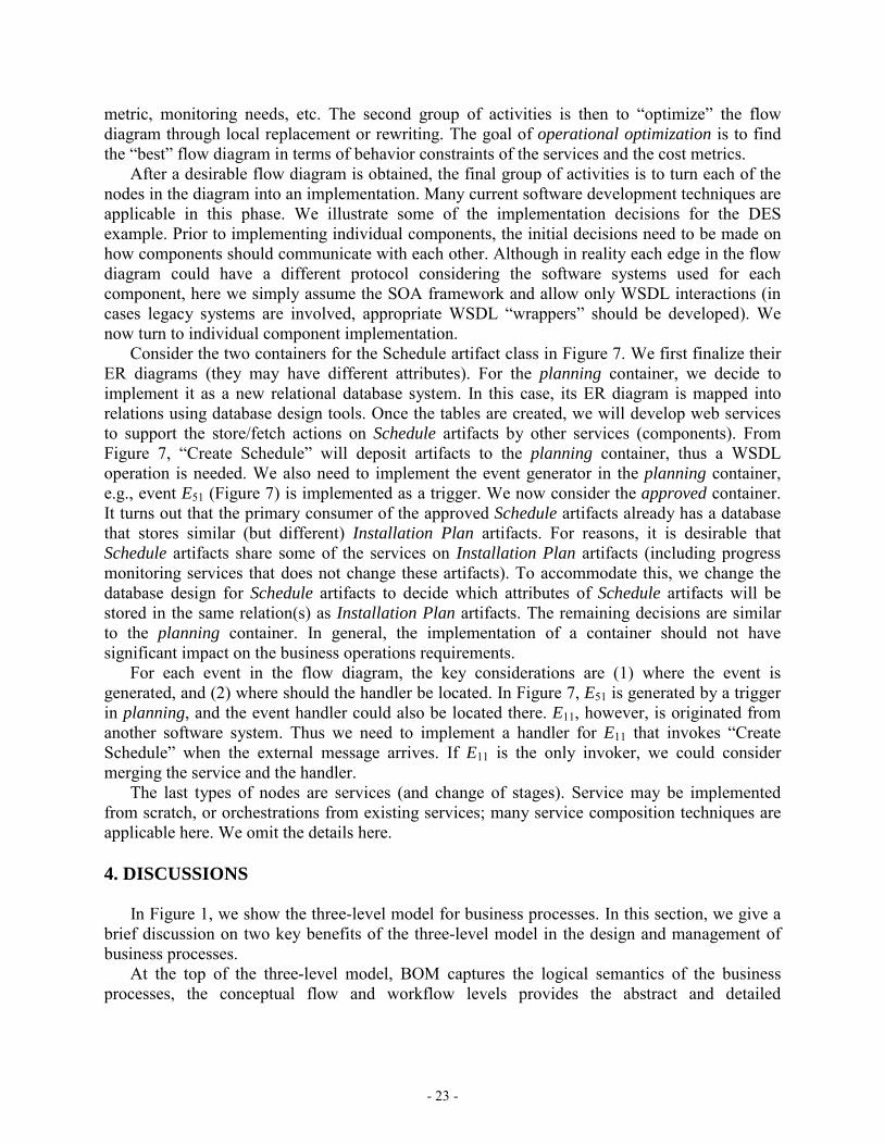
Figure 7: Writing flow diagram: split the repository, adding an event
nodes are explicitly shown through the shapes at edge endpoint. A solid triangle attached to a
node signifies the communication action this node will take. For example, the event handler E11 emits a request message and invokes the “Create Schedule” service, which in turn emits a new Schedule artifact and stores it in the container. Also, change of stage “move to Schedule approved” pulls a Schedule artifact, the small vertical line labeled C denotes a filter with the condition C. The conceptual flow diagram may be verified in at least two aspects. Behavior type checking focuses on the behavior interface well-formed-ness (e.g., reachability, free of deadlocks). Behavior consistency checking ensures that all possible “paths” permitted by the conceptual flow diagram are also permitted by the ECA rules of the BOM. Obtaining a conceptual flow diagram is only a beginning. It is likely that the diagram is not ideal. We consider two examples below to demonstrate how the flow diagram can be modified. Consider the container for Schedule artifacts. It turns out that Schedule artifacts in the planning stage have an identifiable set of attributes that are modified and controlled by one department, while after the approval, new attributes may be added and a set of attributes are not allowed to be changed. The associations of control and updatability of attribute sets and stages may be important for the DES example. A natural solution is to split the Schedule container into two containers labeled with planning and approved, respectively. A careful examination of the ECA rules shows that “Create Schedule” only generates artifacts that are in planning stage. Therefore, we can associate links properly as shown in Figure 7. As another example, we realize that the filter condition C cannot be checked easily by stage changing component due to read restrictions on attributes and inaccessibility of Generic task artifacts. Thus the flow diagram in Figure 6 cannot be directly implemented. One solution is to define an event generator as a trigger in the container for Schedule artifacts in planning stage. (Another kind of event generator, not illustrated here, corresponds to the completion of a service execution.) The modified flow diagram is shown in Figure 7. The proactive action “move to Schedule approved” is replaced with a filtered pull with a database trigger, a reactive service, an event generator, an event handler, and an invocation. The two examples above show how the changes of the flow diagram can help organizing services better and avoid implementation limitations. Other reasons may include performance
(a) Schedule repository, a task, a state-change action (b) Event causing a stage change
Figure 6: Representing behaviors: services, actions, and events
- 23 -
metric, monitoring needs, etc. The second group of activities is then to “optimize” the flow diagram through local replacement or rewriting. The goal of operational optimization is to find the “best” flow diagram in terms of behavior constraints of the services and the cost metrics. After a desirable flow diagram is obtained, the final group of activities is to turn each of the nodes in the diagram into an implementation. Many current software development techniques are applicable in this phase. We illustrate some of the implementation decisions for the DES example. Prior to implementing individual components, the initial decisions need to be made on how components should communicate with each other. Although in reality each edge in the flow diagram could have a different protocol considering the software systems used for each component, here we simply assume the SOA framework and allow only WSDL interactions (in cases legacy systems are involved, appropriate WSDL “wrappers” should be developed). We now turn to individual component implementation. Consider the two containers for the Schedule artifact class in Figure 7. We first finalize their ER diagrams (they may have different attributes). For the planning container, we decide to implement it as a new relational database system. In this case, its ER diagram is mapped into relations using database design tools. Once the tables are created, we will develop web services to support the store/fetch actions on Schedule artifacts by other services (components). From Figure 7, “Create Schedule” will deposit artifacts to the planning container, thus a WSDL operation is needed. We also need to implement the event generator in the planning container, e.g., event E51 (Figure 7) is implemented as a trigger. We now consider the approved container. It turns out that the primary consumer of the approved Schedule artifacts already has a database that stores similar (but different) Installation Plan artifacts. For reasons, it is desirable that Schedule artifacts share some of the services on Installation Plan artifacts (including progress monitoring services that does not change these artifacts). To accommodate this, we change the database design for Schedule artifacts to decide which attributes of Schedule artifacts will be stored in the same relation(s) as Installation Plan artifacts. The remaining decisions are similar to the planning container. In general, the implementation of a container should not have significant impact on the business operations requirements. For each event in the flow diagram, the key considerations are (1) where the event is generated, and (2) where should the handler be located. In Figure 7, E51 is generated by a trigger in planning, and the event handler could also be located there. E11, however, is originated from another software system. Thus we need to implement a handler for E11 that invokes “Create Schedule” when the external message arrives. If E11 is the only invoker, we could consider merging the service and the handler. The last types of nodes are services (and change of stages). Service may be implemented from scratch, or orchestrations from existing services; many service composition techniques are applicable here. We omit the details here. 4. DISCUSSIONS In Figure 1, we show the three-level model for business processes. In this section, we give a brief discussion on two key benefits of the three-level model in the design and management of business processes. At the top of the three-level model, BOM captures the logical semantics of the business processes, the conceptual flow and workflow levels provides the abstract and detailed
- 24 -
(respectively) system design that preserves the BOM semantics. An important property is realization independence that permits changes to the conceptual flow and business workflow implementation (e.g., change of data management tools, software/hardware, service providers, etc.) while preserving the same BOM. Such a freedom to make changes allows improvements and optimization to the business processes. Considers a situation where the current service for Schedule planning is replaced with an outsourced service. In this case, there is no change in the BOM since the new service is just a logically equivalent replacement. However, changes must be made on the conceptual flow diagram since the new service may not have the exact same behaviors. For example, the new service will not be able to access the (internal) database that stores the Schedule artifacts. A solution is then to create another container which will be maintained by the out-sourced service provider. We then need to examine all other control (invocation) and artifact transmission edges in the flow diagram and make necessary changes. When the new conceptual flow diagram is obtained, we can identify current components (events, actions invoked by rules) and make change to those that affected. In this case, the conceptual flow diagrams provide a better tool to reason about the potential service replace. Separation into three levels can also make it easier to manage mappings between the levels and reduce the complexity of making changes at the BOM level. Consider as an example in DES where some vendor tasks require government approval. Suppose that a new rule became effective that requires the approval to be obtained before the start date for selected types of tasks. To reflect this change, rule R3 needs to be adjusted to include in its condition the approval status and the task types. Considering the complaints that the approval process took too long, the government relaxed the rule by allowing a task to start if the approval does not arrive 7 days after the submission was received. Assuming the government always sends an acknowledgement for a request, in DES each acknowledgement causes an event E. The event E will start a 7-day countdown event E1; when E1 happens, the Vendor task artifact needs to record that dates cannot be adjusted if the approval is not received (otherwise, E1 is ignored). It is easy to see that the use of ECA rules allows the changes to be made easily. 5. CONCLUSIONS One of the key challenges to business process management is to enable business managers to understand, design and easily make changes to their business operations, with confidence that their goals are accurately reflected in the underlying IT-level workflows. This chapter presents a promising modeling framework and methodology for addressing this challenge, which is fundamentally centered around data rather than activity flows. More specifically, the framework is based on the notion of “business artifact,” which is used to capture both the information models and the lifecycles of key business entities. The artifact-centric approach has been successfully applied in business process design. We expect that the multi-leveled modeling framework for business workflows described here will further expand the usefulness of the artifact-centric approach to support business process design and evolution. Many aspects of the modeling approach need further study. For example, one area of interest is to develop techniques and tools to aid the design process, specifically, static and dynamic analysis and verification tools. A related topic concerns monitoring workflow executions, in particular, it is desirable to automatically generate monitoring mechanisms from desired metrics given as input. Another area focuses on tools that help to automate design and modification of
- 25 -
workflows. While full automation in the most general case is not achievable, we expect that substantial progress can be achieved in constrained but well-motivated settings. SUGGESTED ADDITIONAL READING The design methodology presented in this chapter is based on earlier work in several different areas, in particular, artifact-centric business process modeling, active databases and other ECA systems, and semantics web services. The concept of business artifact and the idea of modeling business processes in terms of artifact lifecycles were first articulated by Nigam and Caswell in their seminal paper [22]. This paper formed the basis of a substantial effort at IBM Research, which resulted in the “Model-Driven Business Transformation (MDBT)” method and toolkit [15]. This was subsequently incorporated as the “Business Entity Lifecycle Analysis (BELA)” [24] capability pattern into IBM’s Service-Oriented Method and Architecture (SOMA) [1]. The meta-models of [22] and of MDBT [15, 24] can be viewed as lying within the BALSA framework. Reference [22] uses an information model based on (possibly nested) attribute-value pairs, while [15, 24] use ER diagrams for the artifact information model. Both meta-models use detailed finite state machines for the artifact lifecycles. In MDBT, the states of these machines correspond to business-relevant conditions that an artifact can arrive into, and the transitions are annotated with the BOM services that can move the artifact from one state to another one. (This differs from the state machines used in the BALSAbasic meta-model described in the current chapter, where the states correspond to stages of an artifact’s lifecycle, within which numerous BOM services might be applied.) Although the design methodology presented in the current chapter creates BOMs in an ECA-based meta-model, it is nevertheless largely inspired by the methods developed in the MDBT and BELA work. Also, several aspects of the meta-model in reference [22] are used in the Conceptual Flow level (see Section 3.3) of the design methodology presented here. The MDBT modeling technique was applied to enable business transformation in several application contexts involving customer engagements in the areas of finance, supply chain, retail, banking, and pharmaceutical research. Experiences from some of these efforts are reported in [4, 6, 24]. The business managers and subject matter experts involved in these transformations said that the use of artifacts as the basic modeling primitive gave them a kind of “bird’s eye” of their operations that they were not obtaining from the traditional activity-flow based approaches, and that it enabled substantially improved communication between the various stakeholders. Reference [2] describes how IBM’s Component Business Modeling approach, used to develop a partitioning of business functions into clusters appropriate for organizing the operations and assigning accountability, can be enhanced by using an artifact-centric perspective to guide the partitioning into components. References [15, 17, 28] develop approaches for showing correspondences between process-centric views and artifact-centric views of a workflow model. The BALSA framework presented here offers a new perspective on the meta-models developed in [15, 22, 24], by permitting the study of a broad number of meta-models based on the underlying premise of making business artifacts the starting point of business operations modeling. The IBM Research teams behind [2], [22] and the MDBT and BELA work have now joined with others to form Project ArtiFactTM, which is focused on creating a next-generation
- 26 -
artifact-centric meta-model, that can better address emerging challenges such as enabling rich flexibility within a BOM, gracefully handling numerous BOM versions as a business evolves, enabling the coherent specification of a generic BOM with many specializations (as might arise in a global organization with regional variations), and incorporating rich capabilities for representing how people are involved with business operations. The ECA approach for specifying system behavior first appeared in [7, 12], where it was used to specify the behavior of “active” database management systems. Reference [11] provides a general framework for specifying a variety of execution semantics for ECA and other kinds of active database systems. A variety of ECA workflow systems have been developed; for example, reference [21] describes how ECA rules can be used to enable rich flexibility in dynamic adaptability for workflows. Unlike the meta-model presented here, however, none of these previous works place a strong focus on business artifacts as a key construct in their meta-model. Reference [27] describes a highly declarative approach for specifying constraints on how tasks in a workflow should be sequenced. This work is based on Linear Temporal Logic rather than ECA. It will be useful to explore a combination of this declarative approach with the artifact-centric paradigm. Describing the semantics of services with input, output, precondition, and effects is formulated in the OWL-S [19, 20]; in fact OWL-S permits preconditions and effects to refer to an underlying “real world”. More details on semantic web services and compositions can be found in [14]. Reference [25] discusses several choreography languages as well as research issues concerning service choreography. The artifact-centric paradigm provides a natural setting for applying semantic web service perspectives and techniques to business process management, where the artifact information models can be viewed as an underlying “real world.” Work on formally analyzing artifact-centric business process models were recently reported in [5, 9, 10]. Properties investigated in these studies include reachability [9, 10], general temporal constraints [9], and existence of complete execution or dead-end [5]. It was shown that in the general case, the verification problems are undecidable. Decidability results were obtained when rather severe restrictions are placed, e.g., an upper bound on the number of artifacts used during the entire execution. The Vortex model of [13] shares some key notions with the artifact-centric framework presented here. In particular, the focus of processing in Vortex is on “objects”, which correspond closely to artifacts, and the flow of control is governed essentially by condition-action (CA) rules. Unlike the BALSA models, Vortex does not have an explicit concept of an object’s macro-level lifecycle, and Vortex requires attribute assignment to be monotonic and acyclic. Reference [8] develops optimization techniques for Vortex, with an emphasis on data-intensive Vortex workflows. ACKNOWLEDGEMENTS The authors are grateful to all of the IBM Research community that is working on the artifact-centric approach, for conducting the research that forms the basis for this chapter and providing an environment for continued research. The authors thank Nanjangud C. Narendra, Mark Linehan, and two anonymous reviewers for detailed suggestions on the presentation of this chapter. Hull and Su are also grateful for partial support by NSF grants IIS-0415195, CNS-0613998, and IIS-0812578 for the development of this chapter.
- 27 -
REFERENCES 1. A. Arsanjani, S. Ghosh, A. Allam, T. Abdollah, S. Ganapathy, and K. Holley. SOMA: A
method for developing service-oriented solutions. IBM Systems Journal, 47(3):377-396, 2008 2. A. Bercovici, A. Fisher, F. Fournier, G. Rackham, N. Razinkov, and I. Skarbovsky. A
method for service center architecture based on industry standards. In Proc. IEEE Intl. Conf. on Services Computing (SCC), 2008
3. S. Battle, et al. Semantic Web Services Ontology (SWSO), W3C Member Submission, September 2005, http://www.w3.org/Submission/SWSF-SWSO/
4. K. Bhattacharya, N. S. Caswell, S. Kumaran, A. Nigam, and F. Y. Wu. Artifact-centered operational modeling: Lessons from customer engagements. IBM Systems Journal, 46(4):703-721, 2007
5. K. Bhattacharya, C. E. Gerede, R. Hull, R. Liu, and J. Su. Towards formal analysis of artifact-centric business process models. In Proc. 5th Int. Conf. on Business Process Management (BPM), 2007, pp. 288-304
6. K. Bhattacharya, R. Guttman, K. Lyman, F. F. Heath III, S. Kumaran, P. Nandi, F. Wu, P. Athma, C. Freiberg, L. Johannsen, and A. Staudt. A model-driven approach to industrializing discovery processes in pharmaceutical research. IBM Systems Journal, 44(1):145-162, 2005
7. U. Dayal. Active Database Management Systems. In Proc. 3rd Int. Conf. on Data and Knowledge Bases: Improving Usability and Responsiveness, June 1988, Jerusalem, Israel. Morgan Kaufmann, 1988, pp. 150-169
8. G. Dong, R. Hull, B. Kumar, J. Su, and G. Zhou. A Framework for Optimizing Distributed Workflow Executions. In Proc. Int. Workshop on Database Programming Languages (DBPL), 1999, pp. 152-167
9. C. E. Gerede and J. Su. Specification and verification of artifact behaviors in business process models. In Proc. Int. Conf. on Service Oriented Computing (ICSOC), 2007, pp. 181-192
10. C. E. Gerede, K. Bhattacharya, and J. Su. Static analysis of business artifact-centric operational models. In Proc. IEEE Int. Conf. on Service-Oriented Computing and Applications (SOCA), 2007, pp. 133-140
11. S. Ghandeharizadeh, R. Hull, and D. Jacobs. Heraclitus: Elevating deltas to be first-class citizens in a database programming languages. ACM Trans. Database Syst., 21(3):370-426, 1996
12. M. Hsu, R. Ladin, and D. R. McCarthy. An execution model for active data base management systems. In Proc. 3rd Int. Conf. on Data and Knowledge Bases: Improving Usability and Responsiveness, June 1988, Jerusalem, Israel. Morgan Kaufmann, 1988, pp. 171-179
13. R. Hull, F. Llirbat, E. Simon, J. Su, G. Dong, B. Kumar, and G. Zhou. Declarative workflows that support easy modification and dynamic browsing. In Proc. Int. Joint Conf. on Work Activities Coordination and Collaboration, 1999, pp. 69-78
14. R. Hull and J. Su. Tools for composite web services: a short overview. SIGMOD Record 34(2): 86-95, 2005
15. S. Kumaran. Model-driven enterprise. In Proc. Global Enterprise Application Integration (EAI) Summit 2004, Banff, Canada, 2004, pp. 166-180
- 28 -
16. S. Kumaran, R. Liu, and F. Y. Wu. On the duality of information-centric and activity-centric models of business processes. In Proc. Int. Conf. on Advanced Information Systems Engineering, June 2008
17. J. Kűster, K. Ryndina, and H. Gall. Generation of BPM for object life cycle compliance. In Proc. 5th Intl. Conf. on Business Process Management (BPM), 2007
18. R. Liu, K. Bhattacharya, and F. Y. Wu. Modeling business contexture and behavior using business artifacts. In Proc. Int. Conf. on Advanced Information Systems Engineering (CAiSE), 2007
19. D. Martin, et al. OWL-S: Semantic Markup for Web Services, W3C Member Submission. Nov. 2004, http://www.w3.org/Submission/OWL-S/
20. S. A. McIlraith, T. C. Son, and H. Zeng. Semantic web services. In IEEE Intelligent Systems, March/April 2001
21. R. Műller, U. Greiner, E. Rahm. AGENTWORK: A workflow system supporting rule-basede workflow adaptation. Data and Knowledge Engineering 51(2): 223-256, 2004
22. A. Nigam and N. S. Caswell. Business artifacts: An approach to operational specification. IBM Systems Journal, 42(3):428-445, 2003
23. T. Kobayashi, S. Ogoshi, and N. Komoda. A business process design method for applying workflow tools. In Proc. IEEE Int. Conf. on Systems, Man, and Cybernetics, Computational Cybernetics and Simulation, 1997
24. J. K. Strosnider, P. Nandi, S. Kumaran, S. Ghosh, and A. Arsanjani, Model-driven synthesis of SOA solutions. IBM Systems Journal, 47(3): 415-432, 2008.
25. J. Su, T. Bultan, X. Fu, X. Zhao. Towards a theory of web service choreographies. In Proc. Workshop on Web Services and Formal Methods (WS-FM), 2007, pp. 1-16
26. W. M. P. van der Aalst, Business process management demystified: A tutorial on models, systems and standards for workflow management. Lectures on Concurrency and Petri Nets, 2004
27. W. M. P. van der Aalst and M. Pesic. DecSerFlow: Towards a Truly Declarative Service Flow Language. In The Role of Business Processes in Service Oriented Architectures. (Dagstuhl Seminar Proceedings). Published by Internationales Begegnungs- und Forschungszentrum fuer Informatik (IBFI), Schloss Dagstuhl, Germany. See http://drops.dagstuhl.de/opus/volltexte/2006/829/
28. K. Wahler and J. M. Küster. Predicting Coupling of Object-Centric Business Process Implementations. In Proc. 6th Int. Conf. on Business Process Management (BPM), 2008