ion acceleration by laser plasma interaction from...
TRANSCRIPT

Ion Acceleration by Laser Plasma Interaction from Cryogenic Microjets∗
Adrienne Propp†
Harvard College ’17Applied Mathematics
(SULI 2015 at SLAC National Accelerator Laboratory)(Dated: August 16, 2015)
Processes that occur in extreme conditions, such as in the center of stars and large planets, can besimulated in the laboratory using facilities such as SLAC National Accelerator Laboratory and theJupiter Laser Facility (JLF) at Lawrence Livermore National Laboratory (LLNL). These facilitiesallow scientists to investigate the properties of matter by observing their interactions with highpower lasers. Ion acceleration from laser plasma interaction is gaining greater attention today dueto its widespread potential applications, including proton beam cancer therapy and fast ignition forenergy production. Typically, ion acceleration is achieved by focusing a high power laser on thin foiltargets through a mechanism called Target Normal Sheath Acceleration. However, this mechanismis not ideal for creating the high-energy proton beams needed for future applications. Based onresearch and recent experiments, we hypothesized that a pure liquid cryogenic jet would be an idealtarget for exploring new regimes of ion acceleration. Furthermore, it would provide a continuous,pure target, unlike metal foils which are consumed in the interaction and easily contaminated. Inan effort to test this hypothesis, we used the 527 nm split beam, frequency-doubled TITAN laserat JLF. Data from the cryogenic jets was limited due to the flow of current up the jet into thenozzle during the interaction, heating the jet and damaging the orifice. However, we achieved apure proton beam with evidence of a monoenergetic feature. Furthermore, data from gold andcarbon wires showed surprising and interesting results. Preliminary analysis of data from twoion emission diagnostics, Thomson parabola spectrometers (TPs) and radio chromic films (RCFs),suggests that shockwave acceleration occurred rather than target normal sheath acceleration, thestandard mechanism of ion acceleration. Upon completion of the experiment at TITAN, I researchedthe possibility of transforming our liquid cryogenic jets into droplet streams. This type of targetshould solve our problems with the jet as it will prevent the flow of exocurrent into the nozzle. Itis also highly effective as it is even more mass-limited than standard cryogenic jets. Furthermore,jets break up spontaneously anyway. If we can control the breakup, we can synchronize the dropletemission with the laser pulses. In order to assist the team prepare for an experiment later thisyear, I familiarized myself with the physics and theory of droplet formation, calculated values forthe required parameters, and ordered the required materials for modification of the jet. Futureexperiments will test these droplet streams and continue towards the goal of ion acceleration usingcryogenic targets.
CONTENTS
I. Introduction 1
II. TITAN Experiment 2A. Methods 2
1. Laser Specifications 22. Setup 33. Targets 34. Diagnostics 3
B. Results 4C. Analysis 5
III. Piezos 5A. Motivation and Theory 5B. Physical Parameters 6C. Calculations and Next Steps 6
∗ SULI 2015† [email protected]
IV. Conclusions 7
V. Acknowledgements 7
References 7
I. INTRODUCTION
Recent advancements in laser technology have con-tributed to increased interest in ion-beam acceleration bylaser-plasma interaction. With high energy and charge,ion beams have widespread potential applications, in-cluding cancer therapy, fast ignition for energy produc-tion, injectors for accelerators, and simulations of stellarmatter conditions[8]. Scientists are hopeful that furtherinvestigation of ion acceleration will lead to greater un-derstanding of the mechanisms behind it, allowing it toultimately be used for these exciting applications.
Ion acceleration is usually accomplished by focusingthe laser pulse onto a solid density foil target. However,this method is not necessarily the most effective. Basedon recent experiments, we proposed that a pure liquid

2
near-critical density jet would be an ideal target for thisinteraction. Capable of producing the highest proton en-ergies possible with todays laser technologies, it will en-able us to investigate new, more efficient regimes of ionacceleration. Furthermore, it would provide a pure, con-tinuous, mass-limited target that will not be subject toproblems like energy spread or contamination.
This summer I was fortunate enough to participatein an experimental campaign intended to investigatethis proposal. It took place at the Jupiter Laser Fa-cility (JLF) at Lawrence Livermore National Laboratory(LLNL). We used the Titan laser to explore ion accel-eration in high intensity laser plasma interactions. Themajority of the team members were SLAC employees inSiegfried Glenzer’s group, but there were also scientistsfrom LLNL and other institutions.
The goal of this experimental campaign was to accel-erate protons in high intensity laser plasma interactionfrom liquid hydrogen and deuterium targets, and subse-quently characterize the acceleration mechanism. Specif-ically, we wanted to create a pure proton beam, monoen-ergetic features, and high energy protons. While we hadsuccess in many areas, the jet targets were not as suc-cessful as we had hoped they would be. Nevertheless, wecame away from Titan with novel and interesting data,as well greater knowledge about the jet.
Although we experienced obstacles with the jet, we arestill hopeful that this type of target will yield importantresults in the future. Since one of the main problemswith the jet is instability and breakup caused by the flowof current up the jet into the nozzle, one avenue worthexploring is controlled droplet breakup. Upon returningto SLAC, I spent my time investigating this possibility. Iresearched the theory behind Rayleigh breakup in liquidjets, and looked into how we could drive this process withthe piezoelectric effect. My research yielded some goodtheoretical considerations and starting points, but as Idiscovered, piezo-driven droplet breakup leaves much upto trial and error.
In this piece I will first outline the experiment at Ti-tan, the methods and diagnostics we used, as well as somepreliminary results. I go on to describe my findings re-garding piezo-driven jet breakup. I conclude with a fewreflections on what I have learned in my time at SLACand LLNL.
II. TITAN EXPERIMENT
The three goals of this experiment were, specifically, tocreate a pure proton beam, monoenergetic features, andhigh energy protons. We were interested in investigat-ing methods of ion acceleration other than the standardmechanism, Target Normal Sheath Acceleration (TNSA).This mechanism does not provide the purity, narrow en-ergy spectrum, or high energy levels that are requiredfor exciting applications of ion acceleration. For this rea-son, we want to investigate a method called Collisionless
FIG. 1. (Left) This is an example of the energy spectrumgiven by TNSA. Note the low energy cutoff and continuousdecrease in energy. (Right) This is simulation data of CSWA.Note the high energies and peaks in number of ions at specificenergies.
FIG. 2. This is a top-down drawing of the Titan target cham-ber setup. Note the target chamber center and location of thediagnostics.
Shockwave Acceleration (CSWA), that, based on simu-lations, is believed to be better than TNSA in each ofthese respects. See Figure 1.
A. Methods
1. Laser Specifications
We used the west beam laser at Titan, a short pulse,split-beam laser with a pulse duration of about 1 picosec-ond. The diameter of the beam at best focus was 10-15microns due to shot-to-shot fluctuations. This variancealso translated into the energy on target varying between40 and 65 joules. The peak intensity was about 5e19W/cm2. The wavelength was 2w or 527 nm, which meansthat it was a frequency-doubled laser. This is important

3
because it allowed us to achieve good contrast below 1e-9intensity (below the diagnostic detection limit) meaningthere was almost no prepulse before the laser actuallyhit the target. Since we were using thin targets for someshots, this was crucial in ensuring that the target wouldnot be destroyed before the shot even took place.
2. Setup
The experimental setup was rather involved, and wasin fact one of the more complicated to have been usedat the Titan facility. The large target chamber hasseven side ports, three of which we fitted with Thom-son parabolas, a type of ion energy spectrometer. Abovethe target chamber we mounted the cryostat, connectedto a large vat of liquid helium. Several breadboards sur-rounding the target chamber were fitted with various op-tics and streak cameras. Inside the chamber were moreoptics (mirrors, irises, lenses, etc.), RCF mounts, objec-tives near the target chamber center, as well as variousinstallments for viewing and stabilizing the jet. See Fig-ure 2.
3. Targets
An experiment in a facility such as Titan consists ofsetting up a target inside the target chamber, hitting itwith a laser, and measuring various aspects of the inter-action. Therefore, one of the most crucial aspects of anexperiment is the target.
We had three categories of targets for this experiment.The most exciting and novel targets were the hydrogenand deuterium jets (see Figure 3). I was very involvedwith setting these up, and learned that it is very tech-nical and detail-oriented work. It involves cooling thecryostat with liquid helium, liquefying the hydrogen ordeuterium gas by passing the line through a dewar of liq-uid nitrogen, and pumping this liquid into the cryostat.Ideally this creates a pure, steady, continuous stream ofcryogenic material that flows but has a nearly solid outersheath. Then, one must align the jet to the target cham-ber center so it can interact with the laser during a shot.The cryostat was mounted on one of the top ports ofthe chamber, at an angle of 30 degrees from the verticaland 27.29 degrees from target normal in the laser plane.Unfortunately we had many issues with these jets, in-cluding clogged nozzles, instability, and problems withalignment. Despite the team’s experience with jets, wewere only able to successfully hit a jet three times.
We also brought gold and carbon wire targets of var-ious thicknesses for use in this experiment. We thoughtwire would be useful because it mimics the cylindricalshape of the jet. However, the data from the wire provedto be interesting in itself.
Finally, we brought 50 micron CH and CD foil targetsas backups.
FIG. 3. This is a photo of the successful hydrogen jet fromthe Titan experiment.
4. Diagnostics
Thomson parabola spectrometers were one of the suc-cessful diagnostics we used, and another aspect of the ex-periment that I was very involved with. There were threeTPs, each attached to the exterior of the target cham-ber by gate valves so that they could be independentlyvented and pumped down to vacuum. They were locatedat A, B, and G positions, corresponding to laser axis, tar-get normal forward, and target normal backward. In eachchamber was a b field, an e field, and an image plate (SeeFigure 4). The b field deflects vertically based on energy;faster particles spend less time in the field, so are less de-flected, therefore hitting the image plate towards the top.The e field deflects sideways based on charge-to-mass ra-tio; higher charged particles are less deflected, hitting theimage plate close to the center. The image plates thuscapture useful information about the interaction, includ-ing the species accelerated, the energies reached, and theconcentration of ions at each energy. They are scanned,erased, and replaced between shots.
FIG. 4. This is drawing of how a Thomson parabola spec-trometer works.
The other successful diagnostics that I worked withwere radio chromic films. These are stacks of film placedin a strategic location in order to give a rough 2D image
4
of the emission spectrum in that direction. This is not aterribly precise diagnostic, but it is simple, informative,and reliable. The two main types of information theyprovide are the level of energy of the ions (dependingon how many layers are affected) and the quantity ofions (depending on how dark the layers are more opaquemeans more ions). They are affected by both electronsand protons, but the effect of the electrons is less intenseand differs less between layers than the effect of protons.
FIG. 5. This is drawing of the windmill setup of the RCFs.
We used two main setups for this diagnostic. We used awindmill in the target normal forward direction (see Fig-ure 5). Six stacks of RCFs were attached to this, meaningwe could perform six shots before needing to vent the tar-get chamber. These RCF stacks each had a hole in thecenter, through which the ions could pass . This wasto prevent the RCF from interfering with the TP diag-nostic in the target normal forward direction. Towardsthe end of the experiment we used a cylindrical drumarrangement (see Figure 6). This only allowed one stackof RCFs to be loaded at a time, meaning we could onlyperform one shot before venting the chamber. Further-more, the RCF surrounded the target chamber center,meaning that no other diagnostics would yield data forthat shot. However, it gave very useful information sinceit captured the emission spectra in nearly every direction(other than the direction from which the laser came).
B. Results
The data from this experiment has not yet been fullyanalyzed, but we can tentatively say that we found veryinteresting results. The jet was not as successful as wehad hoped, unfortunately. We were able to get two good
FIG. 6. This is drawing of the drum setup of the RCFs.
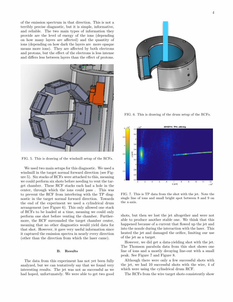
FIG. 7. This is TP data from the shot with the jet. Note thesingle line of ions and small bright spot between 8 and 9 onthe x-axis.
shots, but then we lost the jet altogether and were notable to produce another stable one. We think that thishappened because of a current that flowed up the jet andinto the nozzle during the interaction with the laser. Thisheated the jet and damaged the orifice, limiting our useof the jet as a target.
However, we did get a data-yielding shot with the jet.The Thomson parabola data from this shot shows oneline of ions and a mostly decaying line-out with a smallpeak. See Figure 7 and Figure 8.
Although there were only a few successful shots withthe jet, we had 10 successful shots with the wire, 4 ofwhich were using the cylindrical drum RCF.
The RCFs from the wire target shots consistently show

5
FIG. 8. This is TP line-out data from the shot with the jet.Note the small peak around 1.1 MeV.
horizontal banding relative to the vertical orientation ofthe wire. They appear to show two lines of protons aboveand below the interaction point, which is visible in theRCF. With the data from the cylindrical drum RCF, wesaw quenching in the center and a concentration of elec-trons on the left side. Furthermore, on the RCFs fromthe cylindrical drum, we can see a circular disturbancethat seems to correspond to where the laser would havepassed through. We also see a dark region on the side,interrupting the expected symmetry of a cylindrical tar-get. See Figure 9 for an example of RCF data from thecylindrical drum.
C. Analysis
The data from this experiment is still undergoing anal-ysis, but a few things are evident. For example, it is clearfrom the single line on the TP data that we accelerateda pure proton beam with no contaminants.
Furthermore, although target normal sheath accelera-tion (TNSA) is the standard method of ion acceleration,from our data it appears that this did not occur withthe cylindrical targets. If TNSA had occurred, we wouldhave seen uniform blobs on the RCFs. Instead we sawbanding and modulations in the RCF, as well as peaksin brightness on the image plate data (and correspond-ing small peaks in the line-out readings). These featuresindicate that we were close to achieving something likeshockwave acceleration. We therefore made progress to-wards our goal of creating monoenergetic features anddemonstrating new regimes of ion acceleration.
Furthermore, the RCFs from the wire suggest thatthe interaction may have created a strong magnetic fieldaround the target, caused by electrons traveling up thetarget. In the case of the jet, this high intensity currentwas able to travel up the jet into the nozzle, destroying
FIG. 9. This is RCF data from shot 46 with 10 micron gold.Here are the first four layers of the RCF stack, the first beingthe top image. This layer is darkest so it had the most ionspass through it. However, the lower layers had higher energyions pass through them. Note the horizontal banding, mod-ulations, circular disturbance near the center, and darknesson the left side. These features are consistent throughout theRCF drum data.
the jet and damaging the orifice when intensity was highenough. This is likely the source of our difficulties withthe jet. We were able to get one or two good shots, butthen the jet stopped working altogether.
Unfortunately, we did not see the high levels of energywe were hoping for. Hopefully future experiments withfewer technical difficulties will be able to acheive this.
III. PIEZOS
A. Motivation and Theory
In order to address the problems we had with the jet,we think that a cryogenic droplet stream might be aneven better target for this interaction than a jet. This isbecause the droplets are separated from each other andfrom the nozzle so that exocurrent will not be a problem.
Droplets are also good targets in other ways. Likejets, they are pure and continuous. However, they are

6
FIG. 10. This is an example of high-quality argon (a) andhydrogen (b) droplet streams, courtesy of Costa Fraga et al.Note the regular distance between droplets and lack of threadsor satellite droplets.
even more mass-limited than jets are, which might leadto higher energy density. See Figure 10 for an exampleof a high-quality droplet stream.
We will induce breakup of the cryogenic jet intodroplets with a piezo ceramic component. Piezos workthrough piezoelectricity when an electric current is ap-plied to a piezoelectric material, the material is deformed,contracting and expanding at a certain frequency [1]. Wewill place this piezo ceramic piece behind the nozzle andconnect it to a power supply with an adjustable frequencyin order to transmit vibrations to the jet. According tofluid dynamics, any disturbance in a jet with a wave-length greater than the jets diameter will lead to breakupinto droplets [3]. Therefore, based on the other parame-ters governing droplet breakup and the size of the orificewe want to use, we should be able to control the dropletformation to the point where we can produce a nice, or-derly droplet stream.
B. Physical Parameters
The physics of droplet breakup is largely governed byfluid mechanics and is covered extensively in Eggers andVillermaux. As they explain, surface tension effects andcohesive forces are largely responsible for the sponta-neous breakup of jets into droplet streams[3].
There are several parameters involved in the breakupof droplets, but the most important ones are drivingamplitude, A; Weber number, We; reduced wavenum-ber, x; Ohnesorge number, Oh; and Reynolds number,Re[4]. These depend on the properties of the fluid, in-cluding surface tension, liquid density and dynamic vis-cosity. Adjusting the jet diameter, jet velocity, and driv-ing frequency will allow us to balance these parametersin order to produce the best possible jet. See Figure 11for the relevant equations.
Reduced wavenumber, x, relates the diameter of thejet to the wavelength of the perturbations, or distancebetween the droplets after breakup. When x is close to0.7, this results in the optimum wavelength at which theperturbations in the jet grow fastest. However, x doesnot need to be exactly 0.7 in order to have a nice dropletstream.
Reynolds number, Re, relates to laminarity and is
FIG. 11. These are three of the most important parametersgoverning jet breakup.
inversely related to viscosity: lower Reynolds numbermeans more laminarity, and greater viscosity leads tolower Reynolds number[6]. We would like the flow tobe laminar so that the breakup is more controlled andthe droplets are of higher quality. When Re <2000, wecan be sure that flow is laminar. This will give us anupper limit on jet velocity.
Webers number, We, relates kinematic energy and sur-face energy. We would like the kinetic energy to behigh enough so that the droplets are jetted rather thandripped, but not so high that they are sprayed. Jetteddroplets provide the best target. Therefore, we wouldlike 0.2 <We <4, which further refines the velocity rangeof the jet.
C. Calculations and Next Steps
By balancing the various parameters involved based onthe qualities of the doplets we desire, we have been ableto determine what type of piezo and power supply weneed to buy.
Based on my calculations, as well as the fact that weexpect to use a hydrogen jet with an orifice between 2 and10 microns, I found that the upper bounds for the velocitywill be 66 m/s for a 10 micron orifice, and 330 m/s for a 2micron orifice. The optimal wavelength will be between9 and 45 microns. The frequency should therefore bebetween 1 MHz and 36 MHz.
However, other groups using similar setups have notdriven breakup at anywhere near 36 MHz. This is likelydue to the fact that they had limitations that we do nothave in terms of parameters for the droplets. However,there is also the risk of the coalescence effect as frequencyincreases. We do not want the wavelength to be so smallthat the droplets run into each other. Rather, we want toavoid satellite droplets and threads. We decided to ordera piezo that works at frequencies up to 2 MHz and apower supply that can drive at frequencies up to 10 MHz.This should give us the flexibility we need to adjust thedriving based on what gives us the best droplet stream.Although we have calculated the parameters generally, itis impossible to know what will work best in our specificconditions until we test out the piezo.
The next steps will be setting up the jet source withthe piezo and power supply, and subsequently testing itto make sure we can get a nice droplet strain. We expectthat we will be able to use it in experiments later this

7
year.
IV. CONCLUSIONS
Overall, this internship has been the most intenselyfascinating learning experience I have ever had. I donot come from a strong physics background, so althoughthere was a steep learning curve, I ended up learning farmore than I would have in a situation in which I werewithin my comfort zone. I learned so many physics con-cepts just by doing things for the experiment and askingquestions. I feel that I came away with a solid under-standing of many complicated topics that I have neverbeen exposed to and probably would never have been ex-posed to if not for this internship. Furthermore, I learneda lot about how a team works together during an experi-ment such as the one at Titan, and I was able to learn alot about what it is like to be a scientist by talking withthe other experimentalists. For all of these things, I amextremely grateful to the DOE and the SULI program.
As far as the experiment goes, it was a success in manyrespects. Though the jet was not as easy to set up aswe had hoped, it did produce useful data, showing thatwe created a pure proton beam with some evidence ofa monoenergetic feature. We learned a lot about howthe jet works and what might have caused the problemswith it, and we came away with a strong sense of howwe can improve upon the experimental setup for futureexperiments.
The data we collected from the RCF and TP diagnos-tics with the wire targets turned out to be much moreinteresting and exciting than we expected. We witnessedthings in this experiment that have not been described inprevious literature. It was an amazing experience for meto be part of a real experiment that produced meaningful,
relevant, and impactful results.The time I spent researching piezos was also a great
experience. I learned a lot about how setup for an exper-iment works, as well as how much time it takes to figureout whether or not something is likely to be successful. Ilearned how important it is to pay close attention to de-tail and not jump to conclusions. Furthermore, I learnedabout piezoelectricity and fluid dynamics. Hopefully theresearch I did will be helpful for the team in preparingthe jet source for the next experiment.
V. ACKNOWLEDGEMENTS
I would like to thank Dr. Siegfried Glenzer and hisgroup for welcoming me into their lab for eight weeks de-spite the fact that I had little prior experience or knowl-edge to contribute. I appreciate the fact that they put somuch time into teaching me all that they did in these pastfew weeks and thoroughly involving me in a complicatedexperiment.
Dr. Jongjin Kim, my mentor, was an excellent teacher.He was patient and took a sincere interest in me enjoyingmy work and having something productive to do. It wasa pleasure to be his minion for eight weeks.
Maxence and Christian were also particularly instruc-tive and helpful. They taught me many complicated top-ics and helped me prepare my presentation.
Dr. Enrique Cuellar, Maria Mastrokyriakos, andNancy Qatsha were critical in organizing this internshipand making it so unique. I really appreciate all that theydid to make sure that we not only worked hard, but alsobroadened our horizons and had a good time this sum-mer.
Finally, Id like to thank SLAC National AcceleratorLaboratory and the Department of Energy for giving methis opportunity and making this internship possible.
[1] Wijshoff, Herman The dynamics of the piezo inkjet print-head operation. Physics Reports, 2010.
[2] Xu, Qi and Basaran, Osman a. Computational analysis ofdrop-on-demand drop formation. Physics of Fluids, 2007.
[3] Eggers, Jens and Villermaux, Emmanuel Physics of liq-uid jets. Reports on Progress in Physics, 2008.
[4] van Hoeve, Wim Gekle, Stephan Snoeijer, Jacco H. Ver-sluis, Michel Brenner, Michael P. Lohse, Detlef Breakupof diminutive Rayleigh jets. Physics of Fluids, 2010.
[5] Fraga, R. a Costa Kalinin, A. Khnel, M. Hochhaus,D. C. Schottelius, A. Polz, J. Kaluza, M. C. Neu-mayer, P. Grisenti, R. E.Compact cryogenic source ofperiodic hydrogen and argon droplet beams for relativis-
tic laser-plasma generation. Review of Scientific Instru-ments, 2012.
[6] Nordhage, Li, Z. K. Fridn, C. J. Norman, G. Wiedner,U. On the behavior of micro-spheres in a hydrogen pel-let target. Nuclear Instruments and Methods in PhysicsResearch, Section A: Accelerators, Spectrometers, De-tectors and Associated Equipment, 2005.
[7] Raman THermometry Measurements of Free Evapora-tion from Liquid Water Droplets.
[8] Gauthier, Maxence Etude exp erimentale du pouvoir darr et des ions dans la mati ‘ ere ti ‘ ede et dense : mesurede la distribution des etats de charges d un faisceau dions emergeant de la mati ‘ ere ti ‘ ede et dense. 2013.