io-link interface and system specification · in no event shall the io-link community be liable for...
TRANSCRIPT

IO-Link Interface and
System
Specification
Version 1.1.2 July 2013
Order No: 10.002
IO-Link Interface and System Specification Version 1.1.2 _________________________________________________________________________________________________________
_________________________________________________________________________________________________________ © Copyright IO-Link Community 2013 - All Rights Reserved Page 2 of 262
File name: IOL-Interface-Spec_10002_V112_Jul13 Prepared, approved and released by the IO-Link Community. The IO-Link technology is currently going to be standardized as IEC 61131-9 (FDIS published) based on this document. The IO-Link Community is a D-Liaison member in the corresponding IEC working group. This document covers all Change Requests within the IO-Link CR database up to ID 50.
Any comments, proposals, requests on this document are appreciated through the IO-Link CR database www.io-link-projects.com. Please provide name and email address. Login: IO-Link-V112 Password: Report
Important notes:
NOTE 1 The IO-Link Community Rules shall be observed prior to the development and marketing of IO-Link products. The document can be downloaded from the www.io-link.com portal.
NOTE 2 Any IO-Link device shall provide an associated IODD file. Easy access to the file and potential updates shall be possible. It is the responsibility of the IO-Link device manufacturer to test the IODD file with the help of the IODD-Checker tool available per download from www.io-link.com.
NOTE 3 Any IO-Link devices shall provide an associated manufacturer declaration on the conformity of the device with this specification, its related IODD, and test documents, available per download from www.io-link.com.
Disclaimer:
The attention of adopters is directed to the possibility that compliance with or adoption of IO-Link Community specifications may require use of an invention covered by patent rights. The IO-Link Community shall not be responsible for identifying patents for which a license may be required by any IO-Link Community specification, or for conducting legal inquiries into the legal validity or scope of those patents that are brought to its attention. IO-Link Community specifications are prospective and advisory only. Prospective users are responsible for protecting themselves against liability for infringement of patents.
The information contained in this document is subject to change without notice. The material in this document details an IO-Link Community specification in accordance with the license and notices set forth on this page. This document does not represent a commitment to implement any portion of this specification in any company's products.
WHILE THE INFORMATION IN THIS PUBLICATION IS BELIEVED TO BE ACCURATE, THE IO-LINK COMMUNITY MAKES NO WARRANTY OF ANY KIND, EXPRESS OR IMPLIED, WITH REGARD TO THIS MATERIAL INCLUDING, BUT NOT LIMITED TO ANY WARRANTY OF TITLE OR OWNERSHIP, IMPLIED WARRANTY OF MERCHANTABILITY OR WARRANTY OF FITNESS FOR PARTICULAR PURPOSE OR USE.
In no event shall the IO-Link Community be liable for errors contained herein or for indirect, incidental, special, consequential, reliance or cover damages, including loss of profits, revenue, data or use, incurred by any user or any third party. Compliance with this specification does not absolve manufacturers of IO-Link equipment, from the requirements of safety and regulatory agencies (TÜV, BIA, UL, CSA, etc.).
® is registered trade mark. The use is restricted for members of the IO-Link Community. More detailed terms for the use can be found in the IO-Link Community Rules on www.io-link.com.
Conventions:
In this specification the following key words (in bold text) will be used: may: indicates flexibility of choice with no implied preference. should: indicates flexibility of choice with a strongly preferred implementation. shall: indicates a mandatory requirement. Designers shall implement such mandatory requirements to ensure
interoperability and to claim conformity with this specification. Publisher: IO-Link Community Haid-und-Neu-Str. 7 76131 Karlsruhe Germany Phone: +49 721 / 96 58 590 Fax: +49 721 / 96 58 589 E-mail: [email protected] Web site: www.io-link.com © No part of this publication may be reproduced or utilized in any form or by any means, electronic or mechanical, including photocopying and microfilm, without permission in writing from the publisher.
IO-Link Interface and System © IO-Link – 3 – Version 1.1.2
CONTENTS
FOREWORD ......................................................................................................................... 19 INTRODUCTION ................................................................................................................... 21 1 Scope ............................................................................................................................. 23 2 Normative references ..................................................................................................... 23 3 Terms, definitions, symbols, abbreviated terms and conventions .................................... 24
3.1 Terms and definitions ............................................................................................ 24 3.2 Symbols and abbreviated terms............................................................................. 28 3.3 Conventions .......................................................................................................... 30
3.3.1 General ..................................................................................................... 30 3.3.2 Service parameters ................................................................................... 30 3.3.3 Service procedures .................................................................................... 31 3.3.4 Service attributes ...................................................................................... 31 3.3.5 Figures ...................................................................................................... 31 3.3.6 Transmission octet order ........................................................................... 32 3.3.7 Behavioral descriptions ............................................................................. 32
4 Overview of SDCI (IO-LinkTM) ......................................................................................... 32 4.1 Purpose of technology ........................................................................................... 32 4.2 Positioning within the automation hierarchy ........................................................... 33 4.3 Wiring, connectors and power ............................................................................... 34 4.4 Communication features of SDCI ........................................................................... 34 4.5 Role of a Master .................................................................................................... 36 4.6 SDCI configuration ................................................................................................ 37 4.7 Mapping to fieldbuses ........................................................................................... 37 4.8 Standard structure ................................................................................................. 37
5 Physical Layer (PL) ........................................................................................................ 38 5.1 General ................................................................................................................. 38
5.1.1 Basics ....................................................................................................... 38 5.1.2 Topology ................................................................................................... 38
5.2 Physical layer services .......................................................................................... 39 5.2.1 Overview ................................................................................................... 39 5.2.2 PL services ................................................................................................ 40
5.3 Transmitter/Receiver ............................................................................................. 41 5.3.1 Description method .................................................................................... 41 5.3.2 Electrical requirements .............................................................................. 42 5.3.3 Timing requirements .................................................................................. 46
5.4 Power supply ......................................................................................................... 50 5.4.1 Power supply options ................................................................................ 50 5.4.2 Power-on requirements.............................................................................. 50
5.5 Medium ................................................................................................................. 51 5.5.1 Connectors ................................................................................................ 51 5.5.2 Cable......................................................................................................... 52
6 Standard Input and Output (SIO) .................................................................................... 53 7 Data link layer (DL) ........................................................................................................ 53
7.1 General ................................................................................................................. 53

Version 1.1.2 – 4 – IO-Link Interface and System © IO-Link
7.2 Data link layer services ......................................................................................... 55 7.2.1 DL-B services ............................................................................................ 55 7.2.2 DL-A services ............................................................................................ 66
7.3 Data link layer protocol .......................................................................................... 71 7.3.1 Overview ................................................................................................... 71 7.3.2 DL-mode handler ....................................................................................... 71 7.3.3 Message handler ....................................................................................... 79 7.3.4 Process Data handler ................................................................................ 87 7.3.5 On-request Data handler ........................................................................... 90 7.3.6 ISDU handler ............................................................................................. 93 7.3.7 Command handler ..................................................................................... 97 7.3.8 Event handler ............................................................................................ 99
8 Application layer (AL) ................................................................................................... 102 8.1 General ............................................................................................................... 102 8.2 Application layer services .................................................................................... 103
8.2.1 AL services within Master and Device ...................................................... 103 8.2.2 AL Services ............................................................................................. 104
8.3 Application layer protocol .................................................................................... 112 8.3.1 Overview ................................................................................................. 112 8.3.2 On-request Data transfer ......................................................................... 112 8.3.3 Event processing ..................................................................................... 118 8.3.4 Process Data cycles ................................................................................ 121
9 System management (SM) ........................................................................................... 122 9.1 General ............................................................................................................... 122 9.2 System management of the Master ..................................................................... 122
9.2.1 Overview ................................................................................................. 122 9.2.2 SM Master services ................................................................................. 124 9.2.3 SM Master protocol ................................................................................. 129
9.3 System management of the Device ..................................................................... 136 9.3.1 Overview ................................................................................................. 136 9.3.2 SM Device services ................................................................................. 138 9.3.3 SM Device protocol ................................................................................. 144
10 Device .......................................................................................................................... 151 10.1 Overview ............................................................................................................. 151 10.2 Process Data Exchange (PDE) ............................................................................ 152 10.3 Parameter Manager (PM) .................................................................................... 152
10.3.1 General ................................................................................................... 152 10.3.2 Parameter manager state machine .......................................................... 152 10.3.3 Dynamic parameter ................................................................................. 154 10.3.4 Single parameter ..................................................................................... 155 10.3.5 Block parameter ...................................................................................... 156 10.3.6 Concurrent parameterization access ........................................................ 158 10.3.7 Command handling .................................................................................. 158
10.4 Data Storage (DS) ............................................................................................... 158 10.4.1 General ................................................................................................... 158 10.4.2 Data Storage state machine .................................................................... 158 10.4.3 DS configuration ...................................................................................... 160 10.4.4 DS memory space ................................................................................... 160 10.4.5 DS Index_List .......................................................................................... 161

IO-Link Interface and System © IO-Link – 5 – Version 1.1.2
10.4.6 DS parameter availability ......................................................................... 161 10.4.7 DS without ISDU ...................................................................................... 161 10.4.8 DS parameter change indication .............................................................. 161
10.5 Event Dispatcher (ED) ......................................................................................... 161 10.6 Device features ................................................................................................... 161
10.6.1 General ................................................................................................... 161 10.6.2 Device backward compatibility ................................................................. 161 10.6.3 Protocol revision compatibility ................................................................. 162 10.6.4 Factory settings ....................................................................................... 162 10.6.5 Application reset ...................................................................................... 162 10.6.6 Device reset ............................................................................................ 162 10.6.7 Visual SDCI indication ............................................................................. 162 10.6.8 Parameter access locking ........................................................................ 163 10.6.9 Data Storage locking ............................................................................... 163 10.6.10 Device parameter locking ........................................................................ 163 10.6.11 Device user interface locking ................................................................... 163 10.6.12 Offset time ............................................................................................... 163 10.6.13 Data Storage concept .............................................................................. 164 10.6.14 Block Parameter ...................................................................................... 164
10.7 Device design rules and constraints .................................................................... 164 10.7.1 General ................................................................................................... 164 10.7.2 Process Data ........................................................................................... 164 10.7.3 Communication loss ................................................................................ 164 10.7.4 Direct Parameter ..................................................................................... 164 10.7.5 ISDU communication channel .................................................................. 165 10.7.6 DeviceID rules related to Device variants ................................................ 165 10.7.7 Protocol constants ................................................................................... 165
10.8 IO Device description (IODD) .............................................................................. 166 10.9 Device diagnosis ................................................................................................. 166
10.9.1 Concepts ................................................................................................. 166 10.9.2 Events ..................................................................................................... 167 10.9.3 Visual indicators ...................................................................................... 168
10.10 Device connectivity ............................................................................................. 169 11 Master .......................................................................................................................... 169
11.1 Overview ............................................................................................................. 169 11.1.1 Generic model for the system integration of a Master .............................. 169 11.1.2 Structure and services of a Master .......................................................... 169
11.2 Configuration Manager (CM) ............................................................................... 172 11.2.1 General ................................................................................................... 172 11.2.2 Configuration parameter .......................................................................... 173 11.2.3 State machine of the Configuration Manager ........................................... 175
11.3 Data Storage (DS) ............................................................................................... 177 11.3.1 Overview ................................................................................................. 177 11.3.2 DS data object ......................................................................................... 177 11.3.3 DS state machine .................................................................................... 177 11.3.4 Parameter selection for Data Storage ...................................................... 183
11.4 On-Request Data exchange (ODE) ...................................................................... 183 11.5 Diagnosis Unit (DU) ............................................................................................. 184 11.6 PD Exchange (PDE) ............................................................................................ 185

Version 1.1.2 – 6 – IO-Link Interface and System © IO-Link
11.6.1 General ................................................................................................... 185 11.6.2 Process Data mapping............................................................................. 185 11.6.3 Process Data invalid/valid qualifier status ................................................ 186
11.7 Port and Device configuration tool (PDCT) .......................................................... 187 11.7.1 General ................................................................................................... 187 11.7.2 Basic layout examples ............................................................................. 187
11.8 Gateway application ............................................................................................ 188 11.8.1 General ................................................................................................... 188 11.8.2 Changing Device configuration including Data Storage ............................ 188 11.8.3 Parameter server and recipe control ........................................................ 188 11.8.4 Anonymous parameters ........................................................................... 188 11.8.5 Virtual port mode DIwithSDCI .................................................................. 189
Annex A (normative) Codings, timing constraints, and errors ............................................. 192 A.1 General structure and encoding of M-sequences ................................................. 192
A.1.1 Overview ................................................................................................. 192 A.1.2 M-sequence control (MC) ........................................................................ 192 A.1.3 Checksum / M-sequence type (CKT) ........................................................ 193 A.1.4 User data (PD or OD) .............................................................................. 193 A.1.5 Checksum / status (CKS) ......................................................................... 194 A.1.6 Calculation of the checksum .................................................................... 194
A.2 M-sequence types ............................................................................................... 195 A.2.1 Overview ................................................................................................. 195 A.2.2 M-sequence TYPE_0 ............................................................................... 195 A.2.3 M-sequence TYPE_1_x ........................................................................... 196 A.2.4 M-sequence TYPE_2_x ........................................................................... 197 A.2.5 M-sequence type 3 .................................................................................. 200 A.2.6 M-sequence type usage for STARTUP, PREOPERATE and
OPERATE modes .................................................................................... 200 A.3 Timing constraints ............................................................................................... 201
A.3.1 General ................................................................................................... 201 A.3.2 Bit time .................................................................................................... 201 A.3.3 UART frame transmission delay of Master (ports) .................................... 202 A.3.4 UART frame transmission delay of Devices ............................................. 202 A.3.5 Response time of Devices ....................................................................... 202 A.3.6 M-sequence time ..................................................................................... 202 A.3.7 Cycle time ............................................................................................... 202 A.3.8 Idle time .................................................................................................. 203 A.3.9 Recovery time ......................................................................................... 203
A.4 Errors and remedies ............................................................................................ 203 A.4.1 UART errors ............................................................................................ 203 A.4.2 Wake-up errors ........................................................................................ 204 A.4.3 Transmission errors ................................................................................. 204 A.4.4 Protocol errors ......................................................................................... 204
A.5 General structure and encoding of ISDUs ............................................................ 204 A.5.1 Overview ................................................................................................. 204 A.5.2 I-Service .................................................................................................. 204 A.5.3 Extended length (ExtLength) ................................................................... 205 A.5.4 Index and Subindex ................................................................................. 206 A.5.5 Data ........................................................................................................ 206

IO-Link Interface and System © IO-Link – 7 – Version 1.1.2
A.5.6 Check ISDU (CHKPDU) ........................................................................... 206 A.5.7 ISDU examples ........................................................................................ 207
A.6 General structure and encoding of Events ........................................................... 209 A.6.1 General ................................................................................................... 209 A.6.2 StatusCode type 1 (no details) ................................................................. 209 A.6.3 StatusCode type 2 (with details) .............................................................. 210 A.6.4 EventQualifier .......................................................................................... 211 A.6.5 EventCode............................................................................................... 212
Annex B (normative) Parameter and commands ................................................................ 213 B.1 Direct Parameter page 1 and 2 ............................................................................ 213
B.1.1 Overview ................................................................................................. 213 B.1.2 MasterCommand ..................................................................................... 214 B.1.3 MasterCycleTime and MinCycleTime ....................................................... 215 B.1.4 M-sequence Capability ............................................................................ 216 B.1.5 RevisionID (RID) ..................................................................................... 216 B.1.6 ProcessDataIn ......................................................................................... 217 B.1.7 ProcessDataOut ...................................................................................... 218 B.1.8 VendorID (VID) ........................................................................................ 218 B.1.9 DeviceID (DID) ........................................................................................ 218 B.1.10 FunctionID (FID) ...................................................................................... 218 B.1.11 SystemCommand .................................................................................... 218 B.1.12 Device specific Direct Parameter page 2 ................................................. 218
B.2 Predefined Device parameters ............................................................................ 218 B.2.1 Overview ................................................................................................. 218 B.2.2 SystemCommand .................................................................................... 221 B.2.3 Data Storage Index .................................................................................. 222 B.2.4 Device Access Locks ............................................................................... 223 B.2.5 Profile Characteristic ............................................................................... 224 B.2.6 PD Input Descriptor ................................................................................. 225 B.2.7 PD Output Descriptor .............................................................................. 225 B.2.8 Vendor Name .......................................................................................... 225 B.2.9 Vendor Text ............................................................................................. 225 B.2.10 Product Name ......................................................................................... 225 B.2.11 Product ID ............................................................................................... 225 B.2.12 Product Text ............................................................................................ 225 B.2.13 SerialNumber .......................................................................................... 225 B.2.14 Hardware Revision .................................................................................. 225 B.2.15 Firmware Revision ................................................................................... 226 B.2.16 Application Specific Tag .......................................................................... 226 B.2.17 Error Count .............................................................................................. 226 B.2.18 Device Status .......................................................................................... 226 B.2.19 Detailed Device Status ............................................................................ 227 B.2.20 ProcessDataInput .................................................................................... 227 B.2.21 ProcessDataOutput ................................................................................. 228 B.2.22 Offset Time .............................................................................................. 228 B.2.23 Profile Parameter (reserved).................................................................... 228 B.2.24 Preferred Index........................................................................................ 228 B.2.25 Extended Index ....................................................................................... 229 B.2.26 Profile specific Index (reserved) .............................................................. 229

Version 1.1.2 – 8 – IO-Link Interface and System © IO-Link
Annex C (normative) ErrorTypes (ISDU errors) .................................................................. 230 C.1 General ............................................................................................................... 230 C.2 Application related ErrorTypes ............................................................................ 230
C.2.1 Overview ................................................................................................. 230 C.2.2 Device application error – no details ........................................................ 231 C.2.3 Index not available .................................................................................. 231 C.2.4 Subindex not available ............................................................................ 231 C.2.5 Service temporarily not available ............................................................. 231 C.2.6 Service temporarily not available – local control ...................................... 231 C.2.7 Service temporarily not available – device control ................................... 231 C.2.8 Access denied ......................................................................................... 231 C.2.9 Parameter value out of range .................................................................. 231 C.2.10 Parameter value above limit .................................................................... 232 C.2.11 Parameter value below limit ..................................................................... 232 C.2.12 Parameter length overrun ........................................................................ 232 C.2.13 Parameter length underrun ...................................................................... 232 C.2.14 Function not available.............................................................................. 232 C.2.15 Function temporarily unavailable ............................................................. 232 C.2.16 Invalid parameter set ............................................................................... 232 C.2.17 Inconsistent parameter set ...................................................................... 232 C.2.18 Application not ready ............................................................................... 232 C.2.19 Vendor specific ........................................................................................ 232
C.3 Derived ErrorTypes ............................................................................................. 233 C.3.1 Overview ................................................................................................. 233 C.3.2 Master – Communication error ................................................................. 233 C.3.3 Master – ISDU timeout ............................................................................ 233 C.3.4 Device Event – ISDU error ....................................................................... 233 C.3.5 Device Event – ISDU illegal service primitive ........................................... 233 C.3.6 Master – ISDU checksum error ................................................................ 233 C.3.7 Master – ISDU illegal service primitive ..................................................... 234 C.3.8 Device Event – ISDU buffer overflow ....................................................... 234
Annex D (normative) EventCodes (diagnosis information) .................................................. 235 D.1 General ............................................................................................................... 235 D.2 EventCodes for Devices ...................................................................................... 235
Annex E (normative) Data types ........................................................................................ 238 E.1 General ............................................................................................................... 238 E.2 Basic data types .................................................................................................. 238
E.2.1 General ................................................................................................... 238 E.2.2 BooleanT ................................................................................................. 238 E.2.3 UIntegerT ................................................................................................ 238 E.2.4 IntegerT ................................................................................................... 239 E.2.5 Float32T .................................................................................................. 241 E.2.6 StringT .................................................................................................... 242 E.2.7 OctetStringT ............................................................................................ 242 E.2.8 TimeT ...................................................................................................... 243 E.2.9 TimeSpanT .............................................................................................. 244
E.3 Composite data types .......................................................................................... 245 E.3.1 General ................................................................................................... 245 E.3.2 ArrayT ..................................................................................................... 245

IO-Link Interface and System © IO-Link – 9 – Version 1.1.2
E.3.3 RecordT .................................................................................................. 245 Annex F (normative) Structure of the Data Storage data object .......................................... 249 Annex G (normative) Master and Device conformity ........................................................... 250
G.1 Electromagnetic compatibility requirements (EMC) .............................................. 250 G.1.1 General ................................................................................................... 250 G.1.2 Operating conditions ................................................................................ 250 G.1.3 Performance criteria ................................................................................ 250 G.1.4 Required immunity tests .......................................................................... 251 G.1.5 Required emission tests .......................................................................... 251 G.1.6 Test configurations for Master ................................................................. 252 G.1.7 Test configurations for Devices ................................................................ 253
G.2 Test strategies for conformity .............................................................................. 255 G.2.1 Test of a Device ...................................................................................... 255 G.2.2 Test of a Master ...................................................................................... 255
Annex H (informative) Residual error probabilities ............................................................. 256 H.1 Residual error probability of the SDCI data integrity mechanism .......................... 256 H.2 Derivation of EMC test conditions ........................................................................ 256
Annex I (informative) Example sequence of an ISDU transmission ..................................... 258 Annex J (informative) Recommended methods for detecting parameter changes ............... 260
J.1 CRC signature ..................................................................................................... 260 J.2 Revision counter ................................................................................................. 260
Bibliography ........................................................................................................................ 261 Figure 1 – Example of a confirmed service ........................................................................... 32 Figure 2 – Memory storage and transmission order for WORD based data types .................. 32 Figure 3 – SDCI compatibility with IEC 61131-2 .................................................................... 33 Figure 4 – Domain of the SDCI technology within the automation hierarchy .......................... 33 Figure 5 – Generic Device model for SDCI (Master's view) ................................................... 34 Figure 6 – Relationship between nature of data and transmission types ................................ 35 Figure 7 – Object transfer at the application layer level (AL) ................................................. 36 Figure 8 – Logical structure of Master and Device................................................................. 37 Figure 9 – Three wire connection system .............................................................................. 38 Figure 10 – Topology of SDCI ............................................................................................... 39 Figure 11 – Physical layer (Master) ....................................................................................... 39 Figure 12 – Physical layer (Device) ....................................................................................... 40 Figure 13 – Line driver reference schematics ........................................................................ 42 Figure 14 – Receiver reference schematics .......................................................................... 42 Figure 15 – Reference schematics for SDCI 3-wire connection system ................................. 43 Figure 16 – Voltage level definitions ..................................................................................... 43 Figure 17 – Switching thresholds .......................................................................................... 44 Figure 18 – Format of an SDCI UART frame ......................................................................... 46 Figure 19 – Eye diagram for the 'H' and 'L' detection ............................................................ 47 Figure 20 – Eye diagram for the correct detection of a UART frame ...................................... 47 Figure 21 – Wake-up request ................................................................................................ 49 Figure 22 – Power-on timing for Power1 ............................................................................... 50

Version 1.1.2 – 10 – IO-Link Interface and System © IO-Link
Figure 23 – Pin layout front view ........................................................................................... 51 Figure 24 – Class A and B port definitions ............................................................................ 52 Figure 25 – Reference schematic for effective line capacitance and loop resistance ............. 52 Figure 26 – Structure and services of the data link layer (Master) ......................................... 54 Figure 27 – Structure and services of the data link layer (Device) ......................................... 54 Figure 28 – State machines of the data link layer .................................................................. 71 Figure 29 – Example of an attempt to establish communication ............................................ 72 Figure 30 – Failed attempt to establish communication ......................................................... 72 Figure 31 – Retry strategy to establish communication ......................................................... 73 Figure 32 – Fallback procedure ............................................................................................. 74 Figure 33 – State machine of the Master DL-mode handler ................................................... 74 Figure 34 – Submachine 1 to establish communication ......................................................... 75 Figure 35 – State machine of the Device DL-mode handler ................................................... 78 Figure 36 – SDCI message sequences ................................................................................. 80 Figure 37 – Overview of M-sequence types ........................................................................... 81 Figure 38 – State machine of the Master message handler ................................................... 82 Figure 39 – Submachine "Response 3" of the message handler ............................................ 83 Figure 40 – Submachine "Response 8" of the message handler ............................................ 83 Figure 41 – Submachine "Response 15" of the message handler .......................................... 83 Figure 42 – State machine of the Device message handler ................................................... 86 Figure 43 – Interleave mode for the segmented transmission of Process Data ...................... 88 Figure 44 – State machine of the Master Process Data handler ............................................ 88 Figure 45 – State machine of the Device Process Data handler ............................................ 89 Figure 46 – State machine of the Master On-request Data handler ....................................... 91 Figure 47 – State machine of the Device On-request Data handler ....................................... 92 Figure 48 – Structure of the ISDU ......................................................................................... 93 Figure 49 – State machine of the Master ISDU handler ......................................................... 94 Figure 50 – State machine of the Device ISDU handler ......................................................... 96 Figure 51 – State machine of the Master command handler .................................................. 97 Figure 52 – State machine of the Device command handler .................................................. 98 Figure 53 – State machine of the Master Event handler ...................................................... 100 Figure 54 – State machine of the Device Event handler ...................................................... 101 Figure 55 – Structure and services of the application layer (Master) ................................... 103 Figure 56 – Structure and services of the application layer (Device) ................................... 103 Figure 57 – OD state machine of the Master AL .................................................................. 113 Figure 58 – OD state machine of the Device AL .................................................................. 114 Figure 59 – Sequence diagram for the transmission of On-request Data ............................. 116 Figure 60 – Sequence diagram for On-request Data in case of errors ................................. 117 Figure 61 – Sequence diagram for On-request Data in case of timeout ............................... 117 Figure 62 – Event state machine of the Master AL .............................................................. 118 Figure 63 – Event state machine of the Device AL .............................................................. 119 Figure 64 – Single Event scheduling ................................................................................... 120 Figure 65 – Sequence diagram for output Process Data...................................................... 121

IO-Link Interface and System © IO-Link – 11 – Version 1.1.2
Figure 66 – Sequence diagram for input Process Data ........................................................ 122 Figure 67 – Structure and services of the Master system management ............................... 123 Figure 68 – Sequence chart of the use case "port x setup" ................................................. 124 Figure 69 – Main state machine of the Master system management .................................... 130 Figure 70 – SM Master submachine CheckCompatibility_1 ................................................. 132 Figure 71 – Activity for state "CheckVxy" ............................................................................ 133 Figure 72 – Activity for state "CheckCompV10" ................................................................... 134 Figure 73 – Activity for state "CheckComp" ......................................................................... 134 Figure 74 – Activity (write parameter) in state "RestartDevice" ............................................ 135 Figure 75 – SM Master submachine CheckSerNum_3 ......................................................... 135 Figure 76 – Activity (check SerialNumber) for state CheckSerNum_3 .................................. 136 Figure 77 – Structure and services of the system management (Device) ............................. 137 Figure 78 – Sequence chart of the use case "INACTIVE – SIO – SDCI – SIO" .................... 138 Figure 79 – State machine of the Device system management ............................................ 145 Figure 80 – Sequence chart of a regular Device startup ...................................................... 148 Figure 81 – Sequence chart of a Device startup in compatibility mode ................................ 149 Figure 82 – Sequence chart of a Device startup when compatibility fails ............................. 150 Figure 83 – Structure and services of a Device ................................................................... 151 Figure 84 – The Parameter Manager (PM) state machine ................................................... 153 Figure 85 – Positive and negative parameter checking result .............................................. 155 Figure 86 – Positive block parameter download with Data Storage request ......................... 156 Figure 87 – Negative block parameter download ................................................................. 157 Figure 88 – The Data Storage (DS) state machine .............................................................. 159 Figure 89 – Data Storage request message sequence ........................................................ 160 Figure 90 – Cycle timing ..................................................................................................... 163 Figure 91 – Event flow in case of successive errors ............................................................ 168 Figure 92 – Device LED indicator timing ............................................................................. 168 Figure 93 – Generic relationship of SDCI technology and fieldbus technology .................... 169 Figure 94 – Structure and services of a Master ................................................................... 170 Figure 95 – Relationship of the common Master applications .............................................. 171 Figure 96 – Sequence diagram of configuration manager actions ........................................ 172 Figure 97 – Ports in MessageSync mode ............................................................................ 174 Figure 98 – State machine of the Configuration Manager .................................................... 175 Figure 99 – Main state machine of the Data Storage mechanism ........................................ 177 Figure 100 – Submachine "UpDownload_2" of the Data Storage mechanism ...................... 178 Figure 101 – Data Storage submachine "Upload_7" ............................................................ 179 Figure 102 – Data Storage upload sequence diagram ......................................................... 179 Figure 103 – Data Storage submachine "Download_10" ...................................................... 180 Figure 104 – Data Storage download sequence diagram ..................................................... 180 Figure 105 – State machine of the On-request Data Exchange ........................................... 183 Figure 106 – System overview of SDCI diagnosis information propagation via Events ........ 185 Figure 107 – Process Data mapping from ports to the gateway data stream........................ 186 Figure 108 – Propagation of PD qualifier status between Master and Device ...................... 186

Version 1.1.2 – 12 – IO-Link Interface and System © IO-Link
Figure 109 – Example 1 of a PDCT display layout ............................................................... 187 Figure 110 – Example 2 of a PDCT display layout ............................................................... 188 Figure 111 – Alternative Device configuration ..................................................................... 189 Figure 112 – Virtual port mode "DIwithSDCI" ...................................................................... 190 Figure A.1 – M-sequence control ........................................................................................ 192 Figure A.2 – Checksum/M-sequence type octet .................................................................. 193 Figure A.3 – Checksum/status octet .................................................................................... 194 Figure A.4 – Principle of the checksum calculation and compression .................................. 195 Figure A.5 – M-sequence TYPE_0 ...................................................................................... 196 Figure A.6 – M-sequence TYPE_1_1 .................................................................................. 196 Figure A.7 – M-sequence TYPE_1_2 .................................................................................. 196 Figure A.8 – M-sequence TYPE_1_V .................................................................................. 197 Figure A.9 – M-sequence TYPE_2_1 .................................................................................. 197 Figure A.10 – M-sequence TYPE_2_2 ................................................................................ 198 Figure A.11 – M-sequence TYPE_2_3 ................................................................................ 198 Figure A.12 – M-sequence TYPE_2_4 ................................................................................ 198 Figure A.13 – M-sequence TYPE_2_5 ................................................................................ 199 Figure A.14 – M-sequence TYPE_2_6 ................................................................................ 199 Figure A.15 – M-sequence TYPE_2_V ................................................................................ 199 Figure A.16 – M-sequence timing ........................................................................................ 202 Figure A.17 – I-Service octet .............................................................................................. 204 Figure A.18 – Check of ISDU integrity via CHKPDU ............................................................ 207 Figure A.19 – Examples of request formats for ISDUs ......................................................... 207 Figure A.20 – Examples of response ISDUs ........................................................................ 208 Figure A.21 – Examples of read and write request ISDUs ................................................... 209 Figure A.22 – Structure of StatusCode type 1 ..................................................................... 209 Figure A.23 – Structure of StatusCode type 2 ..................................................................... 210 Figure A.24 – Indication of activated Events ....................................................................... 210 Figure A.25 – Structure of the EventQualifier ...................................................................... 211 Figure B.1 – Classification and mapping of Direct Parameters ............................................ 213 Figure B.2 – MinCycleTime ................................................................................................. 215 Figure B.3 – M-sequence Capability ................................................................................... 216 Figure B.4 – RevisionID ...................................................................................................... 217 Figure B.5 – ProcessDataIn ................................................................................................ 217 Figure B.6 – Index space for ISDU data objects .................................................................. 219 Figure B.7 – Structure of the Offset Time ............................................................................ 228 Figure E.1 – Coding examples of UIntegerT ........................................................................ 239 Figure E.2 – Coding examples of IntegerT .......................................................................... 241 Figure E.3 – Singular access of StringT .............................................................................. 242 Figure E.4 – Coding example of OctetStringT ..................................................................... 243 Figure E.5 – Definition of TimeT ......................................................................................... 243 Figure E.6 – Example of an ArrayT data structure ............................................................... 245 Figure E.7 – Example 2 of a RecordT structure ................................................................... 247
IO-Link Interface and System © IO-Link – 13 – Version 1.1.2
Figure E.8 – Example 3 of a RecordT structure ................................................................... 247 Figure E.9 – Write requests for example 3 .......................................................................... 248 Figure G.1 – Test setup for electrostatic discharge (Master) ............................................... 252 Figure G.2 – Test setup for RF electromagnetic field (Master) ............................................ 252 Figure G.3 – Test setup for fast transients (Master) ............................................................ 253 Figure G.4 – Test setup for RF common mode (Master) ...................................................... 253 Figure G.5 – Test setup for electrostatic discharges (Device) ............................................. 254 Figure G.6 – Test setup for RF electromagnetic field (Device) ............................................ 254 Figure G.7 – Test setup for fast transients (Device) ............................................................ 254 Figure G.8 – Test setup for RF common mode (Device) ...................................................... 255 Figure H.1 – Residual error probability for the SDCI data integrity mechanism .................... 256 Figure I.1 – Example for ISDU transmissions (1 of 2) .......................................................... 258 Table 1 – Service assignments of Master and Device ........................................................... 40 Table 2 – PL_SetMode ......................................................................................................... 40 Table 3 – PL_WakeUp .......................................................................................................... 41 Table 4 – PL_Transfer .......................................................................................................... 41 Table 5 – Electric characteristics of a receiver ...................................................................... 44 Table 6 – Electric characteristics of a Master port ................................................................. 44 Table 7 – Electric characteristics of a Device ........................................................................ 45 Table 8 – Dynamic characteristics of the transmission .......................................................... 48 Table 9 – Wake-up request characteristics ........................................................................... 49 Table 10 – Power-on timing .................................................................................................. 50 Table 11 – Pin assignments .................................................................................................. 51 Table 12 – Cable characteristics ........................................................................................... 52 Table 13 – Cable conductor assignments .............................................................................. 52 Table 14 – Service assignments within Master and Device ................................................... 55 Table 15 – DL_ReadParam ................................................................................................... 55 Table 16 – DL_WriteParam ................................................................................................... 56 Table 17 – DL_Read ............................................................................................................. 57 Table 18 – DL_Write ............................................................................................................. 58 Table 19 – DL_ISDUTransport .............................................................................................. 58 Table 20 – DL_ISDUAbort ..................................................................................................... 60 Table 21 – DL_PDOutputUpdate ........................................................................................... 60 Table 22 – DL_PDOutputTransport ....................................................................................... 61 Table 23 – DL_PDInputUpdate ............................................................................................. 61 Table 24 – DL_PDInputTransport .......................................................................................... 62 Table 25 – DL_PDCycle ........................................................................................................ 62 Table 26 – DL_SetMode ....................................................................................................... 62 Table 27 – DL_Mode ............................................................................................................. 63 Table 28 – DL_Event ............................................................................................................ 64 Table 29 – DL_EventConf ..................................................................................................... 65 Table 30 – DL_EventTrigger ................................................................................................. 65

Version 1.1.2 – 14 – IO-Link Interface and System © IO-Link
Table 31 – DL_Control .......................................................................................................... 65 Table 32 – DL-A services within Master and Device .............................................................. 66 Table 33 – OD ...................................................................................................................... 66 Table 34 – PD ....................................................................................................................... 68 Table 35 – EventFlag ............................................................................................................ 69 Table 36 – PDInStatus .......................................................................................................... 69 Table 37 – MHInfo ................................................................................................................ 70 Table 38 – ODTrig ................................................................................................................ 70 Table 39 – PDTrig ................................................................................................................. 70 Table 40 – Wake-up procedure and retry characteristics ....................................................... 73 Table 41 – Fallback timing characteristics ............................................................................. 74 Table 42 – State transition tables of the Master DL-mode handler ........................................ 75 Table 43 – State transition tables of the Device DL-mode handler ........................................ 78 Table 44 – State transition table of the Master message handler .......................................... 83 Table 45 – State transition tables of the Device message handler ......................................... 87 Table 46 – State transition tables of the Master Process Data handler .................................. 89 Table 47 – State transition tables of the Device Process Data handler .................................. 90 Table 48 – State transition tables of the Master On-request Data handler ............................. 91 Table 49 – State transition tables of the Device On-request Data handler ............................. 92 Table 50 – FlowCTRL definitions .......................................................................................... 94 Table 51 – State transition tables of the Master ISDU handler .............................................. 95 Table 52 – State transition tables of the Device ISDU handler .............................................. 96 Table 53 – Control codes ...................................................................................................... 97 Table 54 – State transition tables of the Master command handler ........................................ 98 Table 55 – State transition tables of the Device command handler ........................................ 99 Table 56 – Event memory ..................................................................................................... 99 Table 57 – State transition tables of the Master Event handler ............................................ 101 Table 58 – State transition tables of the Device Event handler ............................................ 102 Table 59 – AL services within Master and Device ............................................................... 104 Table 60 – AL_Read ........................................................................................................... 104 Table 61 – AL_Write ........................................................................................................... 105 Table 62 – AL_Abort ........................................................................................................... 107 Table 63 – AL_GetInput ...................................................................................................... 107 Table 64 – AL_NewInput ..................................................................................................... 108 Table 65 – AL_SetInput ...................................................................................................... 108 Table 66 – AL_PDCycle ...................................................................................................... 109 Table 67 – AL_GetOutput ................................................................................................... 109 Table 68 – AL_NewOutput .................................................................................................. 110 Table 69 – AL_SetOutput .................................................................................................... 110 Table 70 – AL_Event .......................................................................................................... 111 Table 71 – AL_Control ........................................................................................................ 112 Table 72 – States and transitions for the OD state machine of the Master AL ..................... 113 Table 73 – States and transitions for the OD state machine of the Device AL ..................... 115

IO-Link Interface and System © IO-Link – 15 – Version 1.1.2
Table 74 – State and transitions of the Event state machine of the Master AL..................... 118 Table 75 – State and transitions of the Event state machine of the Device AL..................... 119 Table 76 – SM services within the Master ........................................................................... 125 Table 77 – SM_SetPortConfig ............................................................................................. 125 Table 78 – Definition of the InspectionLevel (IL) ................................................................. 126 Table 79 – Definitions of the Target Modes ......................................................................... 127 Table 80 – SM_GetPortConfig ............................................................................................ 127 Table 81 – SM_PortMode ................................................................................................... 128 Table 82 – SM_Operate ...................................................................................................... 129 Table 83 – State transition tables of the Master system management ................................. 130 Table 84 – State transition tables of the Master submachine CheckCompatibility_1 ............ 132 Table 85 – State transition tables of the Master submachine CheckSerNum_3.................... 135 Table 86 – SM services within the Device ........................................................................... 138 Table 87 – SM_SetDeviceCom ........................................................................................... 139 Table 88 – SM_GetDeviceCom ........................................................................................... 140 Table 89 – SM_SetDeviceIdent ........................................................................................... 141 Table 90 – SM_GetDeviceIdent .......................................................................................... 142 Table 91 – SM_SetDeviceMode .......................................................................................... 143 Table 92 – SM_DeviceMode ............................................................................................... 144 Table 93 – State transition tables of the Device system management ................................. 145 Table 94 – State transition tables of the PM state machine ................................................. 153 Table 95 – Definitions of parameter checks ........................................................................ 155 Table 96 – State transition table of the Data Storage state machine ................................... 159 Table 97 – Overview of the protocol constants for Devices ................................................. 165 Table 98 – Classification of Device diagnosis incidents ....................................................... 166 Table 99 – Timing for LED indicators .................................................................................. 168 Table 100 – Internal variables and Events to control the common Master applications ........ 171 Table 101 – State transition tables of the Configuration Manager ........................................ 176 Table 102 – States and transitions of the Data Storage state machines .............................. 181 Table 103 – State transition table of the ODE state machine ............................................... 183 Table 104 – State transitions of the state machine "DIwithSDCI" ........................................ 190 Table A.1 – Values of communication channel .................................................................... 192 Table A.2 – Values of R/W .................................................................................................. 192 Table A.3 – Values of M-sequence types ............................................................................ 193 Table A.4 – Data types for user data ................................................................................... 193 Table A.5 – Values of PD status ......................................................................................... 194 Table A.6 – Values of the Event flag ................................................................................... 194 Table A.7 – M-sequence types for the STARTUP mode ...................................................... 200 Table A.8 – M-sequence types for the PREOPERATE mode ............................................... 200 Table A.9 – M-sequence types for the OPERATE mode (legacy protocol) ........................... 200 Table A.10 – M-sequence types for the OPERATE mode .................................................... 201 Table A.11 – Recommended MinCycleTimes ...................................................................... 203 Table A.12 – Definition of the nibble "I-Service" .................................................................. 205

Version 1.1.2 – 16 – IO-Link Interface and System © IO-Link
Table A.13 – ISDU syntax ................................................................................................... 205 Table A.14 – Definition of nibble Length and octet ExtLength .............................................. 206 Table A.15 – Use of Index formats ...................................................................................... 206 Table A.16 – Mapping of EventCodes (type 1) .................................................................... 210 Table A.17 – Values of INSTANCE ..................................................................................... 211 Table A.18 – Values of SOURCE ........................................................................................ 211 Table A.19 – Values of TYPE .............................................................................................. 211 Table A.20 – Values of MODE ............................................................................................ 212 Table B.1 – Direct Parameter page 1 and 2 ........................................................................ 214 Table B.2 – Types of MasterCommands .............................................................................. 215 Table B.3 – Possible values of MasterCycleTime and MinCycleTime .................................. 216 Table B.4 – Values of ISDU ................................................................................................ 216 Table B.5 – Values of SIO................................................................................................... 217 Table B.6 – Permitted combinations of BYTE and Length ................................................... 217 Table B.7 – Implementation rules for parameters and commands ........................................ 219 Table B.8 – Index assignment of data objects (Device parameter) ...................................... 220 Table B.9 – Coding of SystemCommand (ISDU) ................................................................. 221 Table B.10 – Data Storage Index assignments .................................................................... 222 Table B.11 – Structure of Index_List ................................................................................... 223 Table B.12 – Device locking possibilities............................................................................. 224 Table B.13 – Device status parameter ................................................................................ 226 Table B.14 – Detailed Device Status (Index 0x0025) ........................................................... 227 Table B.15 – Time base coding and values of Offset Time .................................................. 228 Table C.1 – ErrorTypes ....................................................................................................... 230 Table C.2 – Derived ErrorTypes .......................................................................................... 233 Table D.1 – EventCodes ..................................................................................................... 235 Table D.2 – Basic SDCI EventCodes .................................................................................. 236 Table E.1 – BooleanT ......................................................................................................... 238 Table E.2 – BooleanT coding .............................................................................................. 238 Table E.3 – UIntegerT ......................................................................................................... 239 Table E.4 – IntegerT ........................................................................................................... 239 Table E.5 – IntegerT coding (8 octets) ................................................................................ 240 Table E.6 – IntegerT coding (4 octets) ................................................................................ 240 Table E.7 – IntegerT coding (2 octets) ................................................................................ 240 Table E.8 – IntegerT coding (1 octet) .................................................................................. 240 Table E.9 – Float32T .......................................................................................................... 241 Table E.10 – Coding of Float32T ........................................................................................ 241 Table E.11 – StringT ........................................................................................................... 242 Table E.12 – OctetStringT................................................................................................... 242 Table E.13 – TimeT ............................................................................................................ 243 Table E.14 – Coding of TimeT ............................................................................................ 244 Table E.15 – TimeSpanT .................................................................................................... 244 Table E.16 – Coding of TimeSpanT .................................................................................... 244
IO-Link Interface and System © IO-Link – 17 – Version 1.1.2
Table E.17 – Structuring rules for ArrayT ............................................................................ 245 Table E.18 – Example for the access of an ArrayT .............................................................. 245 Table E.19 – Structuring rules for RecordT ......................................................................... 246 Table E.20 – Example 1 for the access of a RecordT .......................................................... 246 Table E.21 – Example 2 for the access of a RecordT .......................................................... 246 Table E.22 – Example 3 for the access of a RecordT .......................................................... 247 Table F.1 – Structure of the stored DS data object .............................................................. 249 Table F.2 – Associated header information for stored DS data objects ................................ 249 Table G.1 – EMC test conditions for SDCI .......................................................................... 250 Table G.2 – EMC test levels ............................................................................................... 251 Table J.1 – Proper CRC generator polynomials................................................................... 260


IO-Link Interface and System © IO-Link – 19 – Version 1.1.2
INTERNATIONAL ELECTROTECHNICAL COMMISSION 1
____________ 2
3 PROGRAMMABLE CONTROLLERS — 4
5 Part 9: Single-drop digital communication interface 6
for small sensors and actuators (SDCI) 7 8
FOREWORD 9
1) The International Electrotechnical Commission (IEC) is a worldwide organization for standardization comprising 10 all national electrotechnical committees (IEC National Committees). The object of IEC is to promote 11 international co-operation on all questions concerning standardization in the electrical and electronic fields. To 12 this end and in addition to other activities, IEC publishes International Standards, Technical Specifications, 13 Technical Reports, Publicly Available Specifications (PAS) and Guides (hereafter referred to as “IEC 14 Publication(s)”). Their preparation is entrusted to technical committees; any IEC National Committee interested 15 in the subject dealt with may participate in this preparatory work. International, governmental and non-16 governmental organizations liaising with the IEC also participate in this preparation. IEC collaborates closely 17 with the International Organization for Standardization (ISO) in accordance with conditions determined by 18 agreement between the two organizations. 19
2) The formal decisions or agreements of IEC on technical matters express, as nearly as possible, an international 20 consensus of opinion on the relevant subjects since each technical committee has representation from all 21 interested IEC National Committees. 22
3) IEC Publications have the form of recommendations for international use and are accepted by IEC National 23 Committees in that sense. While all reasonable efforts are made to ensure that the technical content of IEC 24 Publications is accurate, IEC cannot be held responsible for the way in which they are used or for any 25 misinterpretation by any end user. 26
4) In order to promote international uniformity, IEC National Committees undertake to apply IEC Publications 27 transparently to the maximum extent possible in their national and regional publications. Any divergence 28 between any IEC Publication and the corresponding national or regional publication shall be clearly indicated in 29 the latter. 30
5) IEC itself does not provide any attestation of conformity. Independent certification bodies provide conformity 31 assessment services and, in some areas, access to IEC marks of conformity. IEC is not responsible for any 32 services carried out by independent certification bodies. 33
6) All users should ensure that they have the latest edition of this publication. 34 7) No liability shall attach to IEC or its directors, employees, servants or agents including individual experts and 35
members of its technical committees and IEC National Committees for any personal injury, property damage or 36 other damage of any nature whatsoever, whether direct or indirect, or for costs (including legal fees) and 37 expenses arising out of the publication, use of, or reliance upon, this IEC Publication or any other IEC 38 Publications. 39
8) Attention is drawn to the Normative references cited in this publication. Use of the referenced publications is 40 indispensable for the correct application of this publication. 41
International Standard IEC 61131-9 has been prepared by subcommittee 65B: Measurement 42 and control devices, in collaboration with subcommittee 65C: Industrial networks, of IEC 43 technical committee 65: Industrial-process measurement, control and automation. 44
The text of this standard is based on the following documents: 45
CDV Report on voting
65B/815/CDV 65B/833/RVC
46 Full information on the voting for the approval of this standard can be found in the report on 47 voting indicated in the above table. 48
This publication has been drafted in accordance with the ISO/IEC Directives, Part 2. 49
A list of all the parts in the IEC 61131 series, published under the general title Programmable 50 controllers, can be found on the IEC website. 51
Version 1.1.2 – 20 – IO-Link Interface and System © IO-Link
The committee has decided that the contents of this publication will remain unchanged until 52 the stability date indicated on the IEC web site under "http://webstore.iec.ch" in the data 53 related to the specific publication. At this date, the publication will be 54
• reconfirmed, 55 • withdrawn, 56 • replaced by a revised edition, or 57 • amended. 58
59
The National Committees are requested to note that for this publication the stability date 60 is 2016. 61
THIS TEXT IS INCLUDED FOR THE INFORMATION OF THE NATIONAL COMMITTEES AND WILL BE 62 DELETED AT THE PUBLICATION STAGE. 63
IMPORTANT – The 'colour inside' logo on the cover page of this publication indicates 64 that it contains colours which are considered to be useful for the correct understanding 65 of its contents. Users should therefore print this document using a colour printer. 66
67
68
69

IO-Link Interface and System © IO-Link – 21 – Version 1.1.2
INTRODUCTION 70
0.1 General 71
IEC 61131-9 is part of a series of standards on programmable controllers and the associated 72 peripherals and should be read in conjunction with the other parts of the series. 73
Where a conflict exists between this and other IEC standards (except basic safety standards), 74 the provisions of this standard should be considered to govern in the area of programmable 75 controllers and their associated peripherals. 76
The increased use of micro-controllers embedded in low-cost sensors and actuators has 77 provided opportunities for adding diagnosis and configuration data to support increasing 78 application requirements. 79
The driving force for the SDCI (IO-Link™1)) technology is the need of these low-cost sensors 80 and actuators to exchange this diagnosis and configuration data with a controller (PC or PLC) 81 using a low-cost, digital communication technology while maintaining backward compatibility 82 with the current DI/DO signals. 83
In fieldbus concepts, the SDCI technology defines a generic interface for connecting sensors 84 and actuators to a Master unit, which may be combined with gateway capabilities to become a 85 fieldbus remote I/O node. 86
Any SDCI compliant Device can be attached to any available interface port of the Master. 87 SDCI compliant Devices perform physical to digital conversion in the Device, and then 88 communicate the result directly in a standard format using "coded switching" of the 24 V I/O 89 signalling line, thus removing the need for different DI, DO, AI, AO modules and a variety of 90 cables. 91
Physical topology is point-to-point from each Device to the Master using 3 wires over 92 distances up to 20 m. The SDCI physical interface is backward compatible with the usual 93 24 V I/O signalling specified in IEC 61131-2. Transmission rates of 4,8 kbit/s, 38,4 kbit/s and 94 230,4 kbit/s are supported. 95
The Master of the SDCI interface detects, identifies and manages Devices plugged into its 96 ports. 97
Tools allow the association of Devices with their corresponding electronic I/O Device Des-98 criptions (IODD) and their subsequent configuration to match the application requirements. 99
The SDCI technology specifies three different levels of diagnostic capabilities: for immediate 100 response by automated needs during the production phase, for medium term response by 101 operator intervention, or for longer term commissioning and maintenance via extended 102 diagnosis information. 103
The structure of this standard is described in 4.8. 104
Conformity with IEC 61131-9 cannot be claimed unless the requirements of Annex G are met. 105
Terms of general use are defined in IEC 61131-1 or in the IEC 60050 series. More specific 106 terms are defined in each part. 107
————————— 1 IO-LinkTM is a trade name of the "IO-Link Community". This information is given for the convenience of users of
this international Standard and does not constitute an endorsement by IEC of the trade name holder or any of its products. Compliance to this standard does not require use of the registered logos for IO-LinkTM. Use of the registered logos for IO-LinkTM requires permission of the "IO-Link Community".

Version 1.1.2 – 22 – IO-Link Interface and System © IO-Link
0.2 Patent declaration 108
The International Electrotechnical Commission (IEC) draws attention to the fact that it is 109 claimed that compliance with this document may involve the use of patents concerning the 110 point-to-point serial communication interface for small sensors and actuators as follows, 111 where the [xx] notation indicates the holder of the patent right: 112
DE 10030845B4 EP 1168271B1 US 6889282B2
[AB] Fieldbus connecting system for actuators or sensors
EP 1203933 B1 [FE] Sensor device for measuring at least one variable
DE 102004035831-A1 [SI] Operational status of a computer system is checked by comparison of actual parameters with reference values and modification to software if needed
DE 102 119 39 A1 US 2003/0200323 A1
[SK] Coupling apparatus for the coupling of devices to a bus system
113 IEC takes no position concerning the evidence, validity and scope of these patent rights. 114
The holders of these patents rights have assured the IEC that they are willing to negotiate 115 licences either free of charge or under reasonable and non-discriminatory terms and 116 conditions with applicants throughout the world. In this respect, the statements of the holders 117 of these patent rights are registered with IEC. 118
Information may be obtained from: 119
[AB] ABB AG Heidelberg Germany
[FE] Festo AG Esslingen Germany
[SI] Siemens AG Otto-Hahn-Ring 6 81739 Munich Germany
[SK] Sick AG Waldkirch Germany
120 Attention is drawn to the possibility that some of the elements of this document may be the 121 subject of patent rights other than those identified above. IEC shall not be held responsible for 122 identifying any or all such patent rights. 123
ISO (www.iso.org/patents) and IEC (http://patents.iec.ch) maintain on-line data bases of 124 patents relevant to their standards. Users are encouraged to consult the databases for the 125 most up to date information concerning patents. 126
127

IO-Link Interface and System © IO-Link – 23 – Version 1.1.2
PROGRAMMABLE CONTROLLERS — 128 129
Part 9: Single-drop digital communication interface 130 for small sensors and actuators (SDCI) 131
132 133 134
1 Scope 135
This part of IEC 61131 specifies a single-drop digital communication interface technology for 136 small sensors and actuators SDCI (commonly known as IO-Link™2), which extends the 137 traditional digital input and digital output interfaces as defined in IEC 61131-2 towards a point-138 to-point communication link. This technology enables the transfer of parameters to Devices 139 and the delivery of diagnostic information from the Devices to the automation system. 140
This technology is mainly intended for use with simple sensors and actuators in factory 141 automation, which include small and cost-effective microcontrollers. 142
This part specifies the SDCI communication services and protocol (physical layer, data link 143 layer and application layer in accordance with the ISO/OSI reference model) for both SDCI 144 Masters and Devices. 145
This part also includes EMC test requirements. 146
This part does not cover communication interfaces or systems incorporating multiple point or 147 multiple drop linkages, or integration of SDCI into higher level systems such as fieldbuses. 148
2 Normative references 149
The following documents, in whole or in part, are normatively referenced in this document and 150 are indispensable for its application. For dated references, only the edition cited applies. For 151 undated references, the latest edition of the referenced document (including any 152 amendments) applies. 153
IEC 60947-5-2, Low-voltage switchgear and controlgear – Part 5-2: Control circuit devices 154 and switching elements – Proximity switches 155
IEC 61000-4-2, Electromagnetic compatibility (EMC) – Part 4-2: Testing and measurement 156 techniques – Electrostatic discharge immunity test 157
IEC 61000-4-3, Electromagnetic compatibility (EMC) – Part 4-3: Testing and measurement 158 techniques – Radiated, radio-frequency, electromagnetic field immunity test 159
IEC 61000-4-4, Electromagnetic compatibility (EMC) – Part 4-4: Testing and measurement 160 techniques – Electrical fast transient/burst immunity test 161
IEC 61000-4-5, Electromagnetic compatibility (EMC) – Part 4-5: Testing and measurement 162 techniques – Surge immunity test 163
————————— 2 IO-LinkTM is a trade name of the "IO-Link Community". This information is given for the convenience of users of
this international Standard and does not constitute an endorsement by IEC of the trade name holder or any of its products. Compliance to this standard does not require use of the registered logos for IO-LinkTM. Use of the registered logos for IO-LinkTM requires permission of the "IO-Link Community".
Version 1.1.2 – 24 – IO-Link Interface and System © IO-Link
IEC 61000-4-6, Electromagnetic compatibility (EMC) – Part 4-6: Testing and measurement 164 techniques – Immunity to conducted disturbances, induced by radio-frequency fields 165
IEC 61000-4-11, Electromagnetic compatibility (EMC) – Part 4-11: Testing and measurement 166 techniques – Voltage dips, short interruptions and voltage variations immunity tests 167
IEC 61000-6-2, Electromagnetic compatibility (EMC) – Part 6-2: Generic standards – 168 Immunity for industrial environments 169
IEC 61000-6-4, Electromagnetic compatibility (EMC) – Part 6-4: Generic standards – 170 Emission standard for industrial environments 171
IEC 61076-2-101, Connectors for electronic equipment – Product requirements – Part 2-101: 172 Circular connectors – Detail specification for M12 connectors with screw-locking 173
IEC 61131-1, Programmable controllers – Part 1: General information 174
IEC 61131-2, Programmable controllers – Part 2: Equipment requirements and tests 175
IEC/TR 62390, Common automation device – Profile guideline 176
ISO/IEC 646:1991, Information technology – ISO 7-bit coded character set for information 177 interchange 178
ISO/IEC 2022, Information technology – Character code structure and extension techniques 179
ISO/IEC 10646, Information technology – Universal Multiple-Octet Coded Character Set 180 (UCS) 181
ISO/IEC 10731, Information technology – Open Systems Interconnection – Basic Reference 182 Model – Conventions for the definition of OSI services 183
ISO/IEC 19505 (all parts), Information technology – Object Management Group Unified 184 Modeling Language (OMG UML) 185
ISO 1177, Information processing – Character structure for start/stop and synchronous 186 character oriented transmission 187
ANSI/IEEE Std 754-1985, IEEE Standard for Floating-Point Arithmetic 188
Internet Engineering Task Force (IETF): RFC 1305 – Network Time Protocol Version 4: 189 Specification, Implementation and Analysis; available at < www.ietf.org > 190
191
3 Terms, definitions, symbols, abbreviated terms and conventions 192
3.1 Terms and definitions 193
For the purposes of this document, the terms and definitions given in IEC 61131-1 and 194 IEC 61131-2, as well as the following apply. 195

IO-Link Interface and System © IO-Link – 25 – Version 1.1.2
3.1.1 196 address 197 part of the M-sequence control to reference data within data categories of a communication 198 channel 199
3.1.2 200 application layer 201 AL 202 <SDCI> part of the protocol responsible for the transmission of Process Data objects and On-203 Request Data objects 204
3.1.3 205 block parameter 206 consistent parameter access via multiple Indices or Subindices 207
3.1.4 208 checksum 209 <SDCI> complementary part of the overall data integrity measures in the data link layer in 210 addition to the UART parity bit 211
3.1.5 212 CHKPDU 213 integrity protection data within an ISDU communication channel generated through XOR 214 processing the octets of a request or response 215
3.1.6 216 coded switching 217 SDCI communication, based on the standard binary signal levels of IEC 61131-2 218
3.1.7 219 COM1 220 SDCI communication mode with transmission rate of 4,8 kbit/s 221
3.1.8 222 COM2 223 SDCI communication mode with transmission rate of 38,4 kbit/s 224
3.1.9 225 COM3 226 SDCI communication mode with transmission rate of 230,4 kbit/s 227
3.1.10 228 COMx 229 one out of three possible SDCI communication modes COM1, COM2, or COM3 230
3.1.11 231 communication channel 232 logical connection between Master and Device 233
Note 1 to entry: Four communication channels are defined: process channel, page and ISDU channel (for 234 parameters), and diagnosis channel. 235
3.1.12 236 communication error 237 unexpected disturbance of the SDCI transmission protocol 238

Version 1.1.2 – 26 – IO-Link Interface and System © IO-Link
3.1.13 239 cycle time 240 time to transmit an M-sequence between a Master and its Device including the following idle 241 time 242
3.1.14 243 Device 244 single passive peer to a Master such as a sensor or actuator 245
Note 1 to entry: Uppercase "Device" is used for SDCI equipment, while lowercase "device" is used in a generic 246 manner. 247
3.1.15 248 Direct Parameters 249 directly (page) addressed parameters transferred acyclically via the page communication 250 channel without acknowledgement 251
3.1.16 252 dynamic parameter 253 part of a Device's parameter set defined by on-board user interfaces such as teach-in buttons 254 or control panels in addition to the static parameters 255
3.1.17 256 Event 257 instance of a change of conditions in a Device 258
Note 1 to entry: Uppercase "Event" is used for SDCI Events, while lowercase "event" is used in a generic manner. 259
Note 2 to entry: An Event is indicated via the Event flag within the Device's status cyclic information, then acyclic 260 transfer of Event data (typically diagnosis information) is conveyed through the diagnosis communication channel. 261
3.1.18 262 fallback 263 transition of a port from coded switching to switching signal mode 264
3.1.19 265 inspection level 266 degree of verification for the Device identity 267
3.1.20 268 interleave 269 segmented cyclic data exchange for Process Data with more than 2 octets through 270 subsequent cycles 271
3.1.21 272 ISDU 273 indexed service data unit used for acyclic acknowledged transmission of parameters that can 274 be segmented in a number of M-sequences 275
3.1.22 276 legacy (Device or Master) 277 Device or Master designed in accordance with [8]3 278
3.1.23 279 M-sequence 280 sequence of two messages comprising a Master message and its subsequent Device 281 message 282
————————— 3 Numbers in square brackets refer to the Bibliography.

IO-Link Interface and System © IO-Link – 27 – Version 1.1.2
3.1.24 283 M-sequence control 284 first octet in a Master message indicating the read/write operation, the type of the 285 communication channel, and the address, for example offset or flow control 286
3.1.25 287 M-sequence error 288 unexpected or wrong message content, or no response 289
3.1.26 290 M-sequence type 291 one particular M-sequence format out of a set of specified M-sequence formats 292
3.1.27 293 Master 294 active peer connected through ports to one up to n Devices and which provides an interface 295 to the gateway to the upper level communication systems or PLCs 296
Note 1 to entry: Uppercase "Master" is used for SDCI equipment, while lowercase "master" is used in a generic 297 manner. 298
3.1.28 299 message 300 <SDCI> sequence of UART frames transferred either from a Master to its Device or vice versa 301 following the rules of the SDCI protocol 302
3.1.29 303 On-request Data 304 acyclically transmitted data upon request of the Master application consisting of parameters 305 or Event data 306
3.1.30 307 physical layer 308 first layer of the ISO-OSI reference model, which provides the mechanical, electrical, 309 functional and procedural means to activate, maintain, and de-activate physical connections 310 for bit transmission between data-link entities 311
Note 1 to entry: Physical layer also provides means for wake-up and fallback procedures. 312 [SOURCE: ISO/IEC 7498-1, 7.7.2, modified — text extracted from subclause, note added] 313
3.1.31 314 port 315 communication medium interface of the Master to one Device 316
3.1.32 317 port operating mode 318 state of a Master's port that can be either INACTIVE, DO, DI, FIXEDMODE, or SCANMODE 319
3.1.33 320 Process Data 321 input or output values from or to a discrete or continuous automation process cyclically 322 transferred with high priority and in a configured schedule automatically after start-up of a 323 Master 324
3.1.34 325 Process Data cycle 326 complete transfer of all Process Data from or to an individual Device that may comprise 327 several cycles in case of segmentation (interleave) 328

Version 1.1.2 – 28 – IO-Link Interface and System © IO-Link
3.1.35 329 single parameter 330 independent parameter access via one single Index or Subindex 331
3.1.36 332 SIO 333 port operation mode in accordance with digital input and output defined in IEC 61131-2 that is 334 established after power-up or fallback or unsuccessful communication attempts 335
3.1.37 336 static parameter 337 part of a Device's parameter set to be saved in a Master for the case of replacement without 338 engineering tools 339
3.1.38 340 switching signal 341 binary signal from or to a Device when in SIO mode (as opposed to the "coded switching" 342 SDCI communication) 343
3.1.39 344 system management 345 SM 346 <SDCI> means to control and coordinate the internal communication layers and the 347 exceptions within the Master and its ports, and within each Device 348
3.1.40 349 UART frame 350 <SDCI> bit sequence starting with a start bit, followed by eight bits carrying a data octet, 351 followed by an even parity bit and ending with one stop bit 352
3.1.41 353 wake-up 354 procedure for causing a Device to change its mode from SIO to SDCI 355
3.1.42 356 wake-up request 357 WURQ 358 physical layer service used by the Master to initiate wake-up of a Device, and put it in a 359 receive ready state 360
3.2 Symbols and abbreviated terms 361
∆fDTRM permissible deviation from data transfer rate (measured in %)
∆VS power supply ripple (measured in V)
AL application layer
BEP bit error probability
C/Q connection for communication (C) or switching (Q) signal (SIO)
CLeff effective total cable capacity (measured in nF)
CQ input capacity at C/Q connection (measured in nF)
DI digital input
DL data link layer
DO digital output
fDTR data transfer rate (measured in bit/s)
H/L high/low signal at receiver output

IO-Link Interface and System © IO-Link – 29 – Version 1.1.2
I/O input / output
ILL input load current at input C/Q to V0 (measured in A)
IODD IO Device Description (see 10.8)
IQ driver current in saturated operating status ON (measured in A)
IQH driver current on high-side driver in saturated operating status ON (measured in A)
IQL driver current on low-side driver in saturated operating status ON (measured in A)
IQPK maximum driver current in unsaturated operating status ON (measured in A)
IQPKH maximum driver current on high-side driver in unsaturated operating status ON (measured in A)
IQPKL maximum driver current on low-side driver in unsaturated operating status ON (measured in A)
IQQ quiescent current at input C/Q to V0 with inactive output drivers (measured in A)
IQWU amplitude of Master’s wake-up request current (measured in A)
IS supply current at V+ (measured in A)
ISIR current pulse supply capability at V+ (measured in A)
LED light emitting diode
L- power supply (-)
L+ power supply (+)
N24 24 V extra power supply (-)
nWU wake-up retry count
On/Off driver’s ON/OFF switching signal
OD On-request Data
OVD signal overload detect
P24 24 V extra power supply (+)
PD Process Data
PDCT port and Device configuration tool
PL physical layer
PLC programmable logic controller
PS power supply (measured in V)
r time to reach a stable level with reference to the beginning of the start bit (measured in TBIT)
RLeff loop resistance of cable (measured in Ω)
s time to exit a stable level with reference to the beginning of the start bit (measured in TBIT)
SDCI single-drop digital communication interface
SIO standard input output (digital switching mode) [IEC 61131-2]
SM system management
t1 UART frame transfer delay on Master (measured in TBIT)
t2 UART frame transfer delay on Device (measured in TBIT)
tA response delay on Device (measured in TBIT)
TBIT bit time (measured in s) tCYC cycle time on M-sequence level (measured in s) tDF fall time (measured in s) TDMT delay time while establishing Master port communication (measured in TBIT)
TDR rise time (measured in s) TDSIO delay time on Device for transition to SIO mode following wake-up request (measured in s) TDWU wake-up retry delay (measured in s)

Version 1.1.2 – 30 – IO-Link Interface and System © IO-Link
tM-sequence M-sequence duration (measured in TBIT)
tidle idle time between two M-sequences (measured in s) tH detection time for high level (measured in s) tL detection time for low level (measured in s) tND noise suppression time (measured in s) TRDL wake-up readiness following power ON (measured in s) TREN receive enable (measured in s) TSD device detect time (measured in s) TWU pulse duration of wake-up request (measured in s)
UART universal asynchronous receiver transmitter
UML Unified Modelling Language [ISO/IEC 19505]
V+ voltage at L+
V0 voltage at L-
VD+L voltage drop on the line between the L+ connections on Master and Device (measured in V) VD0L voltage drop on the line between the L- connections on Master and Device (measured in V) VDQL voltage drop on the line between the C/Q connections on Master and Device (measured in V)
VHYS hysteresis of receiver threshold voltage (measured in V)
VI input voltage at connection C/Q with reference to V0 (measured in V)
VIH input voltage range at connection C/Q for high signal (measured in V)
VIL input voltage range at connection C/Q for low signal (measured in V)
VRQ residual voltage on driver in saturated operating status ON (measured in V)
VRQH residual voltage on high-side driver in operating status ON (measured in V)
VRQL residual voltage on low-side driver in saturated operating status ON (measured in V)
VTH threshold voltage of receiver with reference to V0 (measured in V)
VTHH threshold voltage of receiver for safe detection of a high signal (measured in V)
VTHL threshold voltage of receiver for safe detection of a low signal (measured in V)
WURQ wake-up request pulse
362
3.3 Conventions 363
3.3.1 General 364
The service model, service primitives, and the diagrams shown in this standard are entirely 365 abstract descriptions. The implementation of the services may reflect individual issues and 366 can be different. 367
3.3.2 Service parameters 368
Service primitives are used to represent service provider/consumer interactions 369 (ISO/IEC 10731). They convey parameters which indicate the information available in the 370 provider/ consumer interaction. In any particular interface, not each and every parameter 371 needs to be explicitly stated. 372
The service specification in this standard uses a tabular format to describe the component 373 parameters of the service primitives. The parameters which apply to each group of service 374 primitives are set out in tables. Each table consists of up to five columns: 375
1) parameter name; 376 2) request primitive (.req); 377

IO-Link Interface and System © IO-Link – 31 – Version 1.1.2
3) indication primitive (.ind); 378 4) response primitive (.rsp); and 379 5) confirmation primitive (.cnf). 380
One parameter (or component of it) is listed in each row of each table. Under the appropriate 381 service primitive columns, a code is used to specify the type of usage of the parameter on the 382 primitive specified in the column. 383
M Parameter is mandatory for the primitive. 384 U Parameter is a user option and can or cannot be provided depending on dynamic 385
usage of the service user. When not provided a default value for the parameter is 386 assumed. 387
C Parameter is conditional upon other parameters or upon the environment of the service 388 user. 389
– Parameter is never present. 390 S Parameter is a selected item. 391
Some entries are further qualified by items in brackets. These may be: 392
a) a parameter-specific constraint "(=)" indicates that the parameter is semantically equiva-393 lent to the parameter in the service primitive to its immediate left in the table; 394
b) an indication that some note applies to the entry "(n)" indicates that the following note "n" 395 contains additional information related to the parameter and its use. 396
3.3.3 Service procedures 397
The procedures are defined in terms of: 398
• the interactions between application entities through the exchange of protocol data units; 399 and 400
• the interactions between a communication layer service provider and a communication 401 layer service consumer in the same system through the invocation of service primitives. 402
These procedures are applicable to instances of communication between systems which 403 support time-constrained communications services within the communication layers. 404
3.3.4 Service attributes 405
The nature of the different (Master and Device) services is characterized by attributes. All 406 services are defined from the view of the affected layer towards the layer above. 407
I Initiator of a service (towards the layer above) 408 R Receiver (responder) of a service (from the layer above) 409
3.3.5 Figures 410
For figures that show the structure and services of protocol layers, the following conventions 411 are used: 412
• an arrow with just a service name represents both a request and the corresponding 413 confirmation, with the request being in the direction of the arrow; 414
• a request without confirmation, as well as all indications and responses are labelled as 415 such (i.e. service.req, service.ind, service.rsp). 416
Figure 1 shows the example of a confirmed service. 417

Version 1.1.2 – 32 – IO-Link Interface and System © IO-Link
Service.reqService.ind
Service.rspService.cnf
Initiator Responder
418
Figure 1 – Example of a confirmed service 419
3.3.6 Transmission octet order 420
Figure 2 shows how WORD based data types are transferred from memory to transmission 421 medium and vice versa (i.e. most significant octet transmitted first, see 7.3.3.2 and 7.3.6.1). 422
0 Transmission time t
MSO LSO
MSO
LSOn + 1
n
Transmission
LSO
MSO n + 1
n
"Big endian" "Little endian"Depending on the architecture of the microcontroller in use
Memoryaddresses
Memoryaddresses
423
Key 424
MSO = Most significant octet 425 LSO = Least significant octet 426
Figure 2 – Memory storage and transmission order for WORD based data types 427
3.3.7 Behavioral descriptions 428
For the behavioral descriptions, the notations of UML 2 (ISO/IEC 19505) are used (e.g. state, 429 sequence, activity, timing diagrams, guard conditions). The layout of the associated state-430 transition tables is following IEC/TR 62390. 431
Due to design tool restrictions the following exceptions apply. For state diagrams, a service 432 parameter (in capital letters) is attached to the service name via an underscore character, 433 such as for example in DL_SetMode_INACTIVE. For sequence diagrams, the service 434 primitive is attached via an underscore character instead of a dot, and the service parameter 435 is added in parenthesis, such as for example in DL_Event_ind (OPERATE). Timing 436 constraints are labelled "tm(time in ms)". 437
Asynchronously received service calls are not modelled in detail within state diagrams. 438
4 Overview of SDCI (IO-LinkTM 4) 439
4.1 Purpose of technology 440
Figure 3 shows the basic concept of SDCI. 441 ————————— 4 IO-LinkTM is a trade name of the "IO-Link Community". This information is given for the convenience of users of
this international Standard and does not constitute an endorsement by IEC of the trade name holder or any of its products. Compliance to this standard does not require use of the registered logos for IO-LinkTM. Use of the registered logos for IO-LinkTM requires permission of the "IO-Link Community".

IO-Link Interface and System © IO-Link – 33 – Version 1.1.2
14
3
2
L-
C/Q
L+
IEC 60947-5-2
SIO
COMx 4,8 / 38,4 / 230,4 kbit/s
Pin Signal Definition Standard
1 L+ 24 V IEC 61131-2
2 I/Q Not connected, DI, or DO
IEC 61131-2
3 L- 0 V IEC 61131-2
4 Q "Switching signal" DI(SIO)
IEC 61131-2
C "Coded switching" (COM1, COM2, COM3)
IEC 61131-9
442
Figure 3 – SDCI compatibility with IEC 61131-2 443
The single-drop digital communication interface technology for small sensors and actuators 444 SDCI (commonly known as IO-LinkTM) defines a migration path from the existing digital input 445 and digital output interfaces for switching 24 V Devices as defined in IEC 61131-2 towards a 446 point-to-point communication link. Thus, for example, digital I/O modules in existing fieldbus 447 peripherals can be replaced by SDCI Master modules providing both classic DI/DO interfaces 448 and SDCI. Analog transmission technology can be replaced by SDCI combining its robust-449 ness, parameterization, and diagnostic features with the saving of digital/analog and 450 analog/digital conversion efforts. 451
4.2 Positioning within the automation hierarchy 452
Figure 4 shows the domain of the SDCI technology within the automation hierarchy. 453
Device
Application
Device
Application
Device
Application
Fieldbus interface
Data storage
Parameter server
SDCI
PLC / Host
Fieldbusintegration
Device description
Port 2
Engineering:configuration,parameterization,diagnosis,identification &maintenance
Port 1 Port n
Fieldbus controller
Gateway application
Master
454
Figure 4 – Domain of the SDCI technology within the automation hierarchy 455
The SDCI technology defines a generic interface for connecting sensors and actuators to a 456 Master unit, which may be combined with gateway capabilities to become a fieldbus remote 457 I/O node. 458
Starting point for the design of SDCI is the classic 24 V digital input (DI) defined in 459 IEC 61131-2 and output interface (DO) specified in Table 6. Thus, SDCI offers connectivity of 460 classic 24 V sensors ("switching signals") as a default operational mode. Additional connec-461 tivity is provided for actuators when a port has been configured into "single-drop 462 communication mode". 463

Version 1.1.2 – 34 – IO-Link Interface and System © IO-Link
Many sensors and actuators nowadays are already equipped with microcontrollers offering a 464 UART interface that can be extended by addition of a few hardware components and protocol 465 software to support SDCI communication. This second operational mode uses "coded 466 switching" of the 24 V I/O signalling line. Once activated, the SDCI mode supports 467 parameterization, cyclic data exchange, diagnosis reporting, identification & maintenance 468 information, and external parameter storage for Device backup and fast reload of replacement 469 devices. Sensors and actuators with SDCI capability are referred to as "Devices" in this 470 standard. To improve start-up performance these Devices usually provide non-volatile storage 471 for parameters. 472
NOTE Configuration and parameterization of Devices is supported through an XML-based device description (see 473 [6]), which is not part of this standard. 474
4.3 Wiring, connectors and power 475
The default connection (port class A) comprises 4 pins (see Figure 3). The default wiring for 476 port class A complies with IEC 60947-5-2 and uses only three wires for 24 V, 0 V, and a 477 signal line. The fourth wire may be used as an additional signal line complying with 478 IEC 61131-2. 479
Five pins connections (port class B) are specified for Devices requiring additional power from 480 an independant 24 V power supply. 481
NOTE A port class A Device using the fourth wire is not compatible with a port class B Master. 482
Maximum length of cables is 20 m, shielding is not required. 483
4.4 Communication features of SDCI 484
The generic Device model is shown in Figure 5 and explained in the following paragraphs. 485
Process data
0...32 octetsout
0...32 octetsin 0232
Index 0...65535,232 octets/indexmaximum
0232Subindex 0 entire record
Parameter andcommands
0...32 octets
Event memory(diagnosis)
......
...
0x00
Subindex 1...255 selective
0xFFFF
Direct Parameterpage 1+2
015
51 10 5
486
Figure 5 – Generic Device model for SDCI (Master's view) 487
A Device may receive Process Data (out) to control a discrete or continuous automation 488 process or send Process Data (in) representing its current state or measurement values. The 489 Device usually provides parameters enabling the user to configure its functions to satisfy 490 particular needs. To support this case a large parameter space is defined with access via an 491 Index (0 to 65535; with a predefined organization) and a Subindex (0 to 255). 492

IO-Link Interface and System © IO-Link – 35 – Version 1.1.2
The first two index entries 0 and 1 are reserved for the Direct Parameter page 1 and 2 with a 493 maximum of 16 octets each. Parameter page 1 is mainly dedicated to Master commands such 494 as Device startup and fallback, retrieval of Device specific operational and identification 495 information. Parameter page 2 allows for a maximum of 16 octets of Device specific 496 parameters. 497
The other indices (2 to 65535) each allow access to one record having a maximum size of 232 498 octets. Subindex 0 specifies transmission of the complete record addressed by the Index, 499 other subindices specify transfer of selected data items within the record. 500
Within a record, individual data items may start on any bit offset, and their length may range 501 from 1 bit to 232 octets, but the total number of data items in the record cannot exceed 255. 502 The organization of data items within a record is specified in the IO Device Description 503 (IODD). 504
All changes of Device condition that require reporting or intervention are stored within an 505 Event memory before transmission. An Event flag is then set in the cyclic data exchange to 506 indicate the existence of an Event. 507
Communication between a Master and a Device is point-to-point and is based on the principle 508 of a Master first sending a request message and then a Device sending a response message 509 (see Figure 36). Both messages together are called an M-sequence. Several M-sequence 510 types are defined to support user requirements for data transmission (see Figure 37). 511
Data of various categories are transmitted through separate communication channels within 512 the data link layer, as shown in Figure 6. 513
• Operational data such as Device inputs and outputs is transmitted through a process 514 channel using cyclic transfer. Operational data may also be associated with qualifiers such 515 as valid/invalid. 516
• Configuration and maintenance parameters are transmitted using acyclic transfers. A page 517 channel is provided for direct access to parameter pages 1 and 2, and an ISDU channel is 518 used for accessing additional parameters and commands. 519
• Device events are transmitted using acyclic transfers through a diagnostic channel. Device 520 events are reported using 3 severity levels, error, warning, and notification. 521
Cyclic (default)Cyclic (default)
On-request (acyclic)On-request (acyclic)
Nature of Data
OperationOperation ProcessProcess
CommunicationChannel
Configuration/maintenanceConfiguration/maintenance
EventsEvents
ErrorsErrors
WarningsWarnings
NotificationsNotifications
Direct Parameter(Page 1 or 2)Direct Parameter(Page 1 or 2)
Transmission Type
PagePage
DiagnosisDiagnosis
Parameter(Index >1)Parameter(Index >1) ISDUISDU
Data Categories
Input, OutputInput, Output
Valid, InvalidValid, Invalid
522
Figure 6 – Relationship between nature of data and transmission types 523

Version 1.1.2 – 36 – IO-Link Interface and System © IO-Link
The first octet of a Master message controls the data transfer direction (read/write) and the 524 type of communication channel. 525
Figure 7 shows each port of a Master has its own data link layer which interfaces to a 526 common master application layer. Within the application layer, the services of the data link 527 layer are translated into actions on Process Data objects (input/output), On-request Data 528 objects (read/write), and events. Master applications include a Configuration Manager (CM), 529 Data Storage mechanism (DS), Diagnosis Unit (DU), On-request Data Exchange (ODE), and a 530 Process Data Exchange (PDE). 531
System management checks identification of the connected Devices and adjusts ports and 532 Devices to match the chosen configuration and the properties of the connected Devices. It 533 controls the state machines in the application (AL) and data link layers (DL), for example at 534 start-up. 535
Sys
tem
man
agem
ent
Sys
tem
man
agem
ent
DLDL
Input
Output
Read Write
Device technologyDevice technology
Cycliccommunicationchannel(process data)
Acycliccommunication
channels(on-request)
Sys
tem
man
agem
ent
Sys
tem
man
agem
ent
... ...
Input
Output
Read Write
DLDL
PortPort
DLDL
PortPort
DLDL
PortPort
Applicationlayer (AL)
Data linklayer (DL)Physicallayer (PL)
Master applications
Process data objectsOn-request data objects
Process data objectsOn-request data objects
Events
Events
536
Figure 7 – Object transfer at the application layer level (AL) 537
4.5 Role of a Master 538
A Master accommodates 1 to n ports and their associated data link layers. During start-up it 539 changes the ports to the user-selected port modes, which can be INACTIVE, DI, DO, 540 FIXEDMODE, or SCANMODE. If communication is requested, the Master uses a special 541 wake-up current pulse to initiate communication with the Device. The Master then auto-542 adjusts the transmission rate to COM1, COM2, or COM3 (see Table 8) and checks the 543 "personality" of the connected Device, i.e. its VendorID, DeviceID, and communication 544 properties. 545
If there is a mismatch between the Device parameters and the stored parameter set within the 546 Master, the parameters in the Device are overwritten (see 11.3) or the stored parameters 547 within the master are updated depending on configuration. 548

IO-Link Interface and System © IO-Link – 37 – Version 1.1.2
It is also possible to start a device in DI mode, switch to SDCI communication for 549 configuration and parameterization and then use the fallback command (see 11.8.5) to switch 550 back to DI mode for normal operation. 551
Coordination of the ports is also a task of the Master which the user can configure through the 552 selection of port cycle modes. In "FreeRunning" mode, each port defines its own cycle based 553 on the properties of the connected Device. In "MessageSync" mode, messages sent on the 554 connected ports start at the same time or in a defined staggered manner. In "FixedValue" 555 mode, each port uses a user-defined fixed cycle time (see 11.2.2.2). 556
The Master is responsible for the assembling and disassembling of all data from or to the 557 Devices (see Clause 11). 558
The Master provides a Data Storage area of at least 2 048 octets per Device for backup of 559 Device data (see 11.3). The Master may combine this Device data together with all other 560 relevant data for its own operation, and make this data available for higher level applications 561 for Master backup purpose or recipe control (see 11.8.3). 562
4.6 SDCI configuration 563
Engineering support for a Master is usually provided by a Port and Device Configuration Tool 564 (PDCT). The PDCT configures both port properties and Device properties (see parameters 565 shown in Figure 5). It combines both an interpreter of the I/O Device Description (IODD) and a 566 configurator (see 11.7). The IODD provides all the necessary properties to establish 567 communication and the necessary parameters and their boundaries to establish the desired 568 function of a sensor or actuator. The PDCT also supports the compilation of the Process Data 569 for propagation on the fieldbus and vice versa. 570
4.7 Mapping to fieldbuses 571
Integration of a Master within a fieldbus system, i.e. the definition of gateway functions for 572 exchanging data with higher level entities on a fieldbus, is out of the scope of this standard. 573
EXAMPLE These functions include mapping of the Process Data exchange, realization of program-controlled 574 parameterization or a remote parameter server, or the propagation of diagnosis information. 575
The integration of a PDCT into engineering tools of a particular fieldbus is out of the scope of 576 this standard. 577
4.8 Standard structure 578
Figure 8 shows the logical structure of the Master and Device. Clause 5 specifies the Physical 579 Layer (PL) of SDCI, Clause 6 specifies details of the SIO mode. Clause 7 specifies Data Link 580 Layer (DL) services, protocol, wake-up, M-sequences, and the DL layer handlers. Clause 8 581 specifies the services and the protocol of the Application Layer (AL) and Clause 9 the System 582 Management responsibilities (SM). 583
Master Device
AL
DL
PL
DL
PL
DL
PL
...
...
DL
PL
DL
PL
DL
PL
DL
PL
DL
PL
DL
PL
...
...
...
...
SM
AL
DL
PL
AL
DL
PL
DL
PL
SIO
Medium
SIO SM
CM DS ODE DU PDE PM DS ED PDEPM DS ED PDE
584
Figure 8 – Logical structure of Master and Device 585

Version 1.1.2 – 38 – IO-Link Interface and System © IO-Link
Clause 10 specifies Device applications and features. These include Process Data Exchange 586 (PDE), Parameter Management (PM), Data Storage (DS), and Event Dispatcher (ED). 587 Technology specific applications are not part of this standard. They may be specified in 588 profiles for particular Device families. 589
Clause 11 specifies Master applications and features. These include Process Data Exchange 590 (PDE), On-request Data Exchange (ODE), Configuration Management (CM), Data Storage 591 (DS) and Diagnosis Unit (DU). 592
Several normative and informative annexes are included. Annex A defines the available M-593 sequence types. Annex B describes the parameters of the Direct Parameter page and the 594 fixed Device parameters. Annex C lists the error types in case of acyclic transmissions and 595 Annex D the EventCodes (diagnosis information of Devices). Annex E specifies the available 596 basic and composite data types. Annex F defines the structure of Data Storage objects. 597 Annex G deals with conformity and electromagnetic compatibility test requirements and 598 Annex H provides graphs of residual error probabilities, demonstrating the level of SDCI's 599 data integrity. The informative Annex I provides an example of the sequence of acyclic data 600 transmissions. The informative Annex J explains two recommended methods for detecting 601 parameter changes in the context of Data Storage. 602
5 Physical Layer (PL) 603
5.1 General 604
5.1.1 Basics 605
The 3-wire connection system of SDCI is based on the specifications in IEC 60947-5-2. The 606 three lines are used as follows: (L+) for the 24 V power supply, (L-) for the ground line, and 607 (C/Q) for the switching signal (Q) or SDCI communication (C), as shown in Figure 9. 608
Master Device
L+
C/Q
L- 609
Figure 9 – Three wire connection system 610
NOTE Binary sensors compliant with IEC 60947-5-2 are compatible with the SDCI 3-wire connection system 611 (including from a power consumption point of view). 612
Support of the SDCI 3-wire connection system is mandatory for Master. Ports with this 613 characteristic are called port class A. 614
Port class A uses a four pin connector. The fourth wire may be used as an additional signal 615 line complying with IEC 61131-2. Its support is optional in both Masters and Devices. 616
Five wire connections (port class B) are specified for Devices requiring additional power from 617 an independant 24 V power supply (see 5.5.1). 618
NOTE A port class A Device using the fourth wire is not compatible with a port class B Master. 619
5.1.2 Topology 620
The SDCI system topology uses point-to-point links between a Master and its Devices as 621 shown in Figure 10. The Master may have multiple ports for the connection of Devices. Only 622 one Device shall be connected to each port. 623

IO-Link Interface and System © IO-Link – 39 – Version 1.1.2
Master
1 2 3 ... n
1 2 3 n
SDCI links
Devices
Ports
624
Figure 10 – Topology of SDCI 625
5.2 Physical layer services 626
5.2.1 Overview 627
Figure 11 shows an overview of the Master's physical layer and its service primitives. 628
System Management
PL-Transfer.req PL-Transfer.indPL-WakeUp.req
SIODI / DO
PL-SetMode.req
Port x handlerMaster
DL-mode handler Message handler
Wake-up Switching signalCoded switchingInactive
Data Link Layer
Mode switch
Physical Layer (port)
NC/DI / DO
Option
Medium 629
Figure 11 – Physical layer (Master) 630
The physical layer specifies the operation of the C/Q line in Figure 3 and the associated line 631 driver (transmitter) and receiver of a particular port. The Master operates this line in three 632 main modes (see Figure 11): inactive, "Switching signal" (DI/DO), or "Coded switching" 633 (COMx). The service PL-SetMode.req is responsible for switching into one of these modes. 634
If the port is in inactive mode, the C/Q line shall be high impedance (floating). In SIO mode, 635 the port can be used as a standard input or output interface according to the definitions of 636 IEC 61131-2 or in Table 6 respectively. The communication layers of SDCI are bypassed as 637 shown in Figure 11; the signals are directly processed within the Master application. In SDCI 638 mode, the service PL_WakeUp.req creates a special signal pattern (current pulse) that can be 639 detected by an SDCI enabled Device connected to this port (see 5.3.3.3). 640
Figure 12 shows an overview of the Device's physical layer and its service primitives. 641
The physical layer of a Device according to Figure 12 follows the same principle, except that 642 there is no inactive state. By default at power on or cable reconnection, the Device shall 643 operate in the SIO mode, as a digital input (from a Master's point of view). The Device shall 644 always be able to detect a wake-up current pulse (wake-up request). The service 645 PL_WakeUp.ind reports successful detection of the wake-up request (usually a 646 microcontroller interrupt), which is required for the Device to switch to the SDCI mode. 647
A special MasterCommand (fallback) sent via SDCI causes the Device to switch back to SIO 648 mode. 649
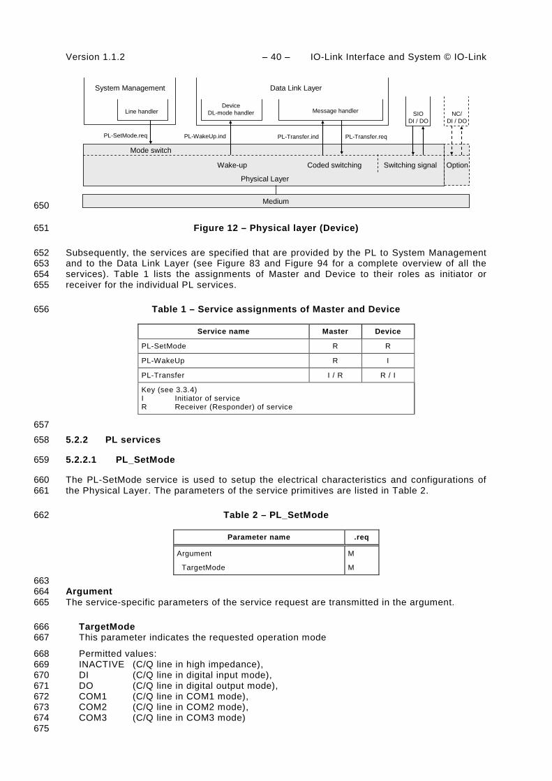
Version 1.1.2 – 40 – IO-Link Interface and System © IO-Link
System Management
PL-Transfer.ind PL-Transfer.reqPL-WakeUp.ind
SIODI / DO
PL-SetMode.req
Line handlerDevice
DL-mode handler Message handler
Wake-up Switching signalCoded switching
Data Link Layer
Physical Layer
Mode switch
NC/DI / DO
Option
Medium 650
Figure 12 – Physical layer (Device) 651
Subsequently, the services are specified that are provided by the PL to System Management 652 and to the Data Link Layer (see Figure 83 and Figure 94 for a complete overview of all the 653 services). Table 1 lists the assignments of Master and Device to their roles as initiator or 654 receiver for the individual PL services. 655
Table 1 – Service assignments of Master and Device 656
Service name Master Device
PL-SetMode R R
PL-WakeUp R I
PL-Transfer I / R R / I
Key (see 3.3.4) I Initiator of service R Receiver (Responder) of service
657 5.2.2 PL services 658
5.2.2.1 PL_SetMode 659
The PL-SetMode service is used to setup the electrical characteristics and configurations of 660 the Physical Layer. The parameters of the service primitives are listed in Table 2. 661
Table 2 – PL_SetMode 662
Parameter name .req
Argument M
TargetMode M
663 Argument 664 The service-specific parameters of the service request are transmitted in the argument. 665
TargetMode 666 This parameter indicates the requested operation mode 667
Permitted values: 668 INACTIVE (C/Q line in high impedance), 669 DI (C/Q line in digital input mode), 670 DO (C/Q line in digital output mode), 671 COM1 (C/Q line in COM1 mode), 672 COM2 (C/Q line in COM2 mode), 673 COM3 (C/Q line in COM3 mode) 674 675

IO-Link Interface and System © IO-Link – 41 – Version 1.1.2
5.2.2.2 PL_WakeUp 676
The PL-WakeUp service initiates or indicates a specific sequence which prepares the 677 Physical Layer to send and receive communication requests (see 5.3.3.3). This unconfirmed 678 service has no parameters. Its success can only be verified by a Master by attempting to 679 communicate with the Device. The service primitives are listed in Table 3. 680
Table 3 – PL_WakeUp 681
Parameter name .req .ind
<none>
682 5.2.2.3 PL_Transfer 683
The PL-Transfer service is used to exchange the SDCI data between Data Link Layer and 684 Physical Layer. The parameters of the service primitives are listed in Table 4. 685
Table 4 – PL_Transfer 686
Parameter name .req ind.
Argument
Data
M M
Result (+) S
Result (-) S
Status M
687 Argument 688 The service-specific parameters of the service request are transmitted in the argument. 689
Data 690 This parameter contains the data value which is transferred over the SDCI interface. 691
Permitted values: 0…255 692
Result (+): 693 This selection parameter indicates that the service request has been executed successfully. 694
Result (-): 695 This selection parameter indicates that the service request failed. 696
Status 697 This parameter contains supplementary information on the transfer status. 698
Permitted values: 699 PARITY_ERROR (UART detected a parity error), 700 FRAMING_ERROR (invalid UART stop bit detected), 701 OVERRUN (octet collision within the UART) 702 703
5.3 Transmitter/Receiver 704
5.3.1 Description method 705
The physical layer is specified by means of electrical and timing requirements. Electrical 706 requirements specify signal levels and currents separately for Master and Device in the form 707

Version 1.1.2 – 42 – IO-Link Interface and System © IO-Link
of reference schematics. Timing requirements specify the signal transmission process 708 (specifically the receiver) and a special signal detection function. 709
5.3.2 Electrical requirements 710
5.3.2.1 General 711
The line driver is specified by a reference schematic corresponding to Figure 13. On the 712 Master side, a transmitter comprises a combination of two line drivers and one current sink. 713 On the Device side, in its simplest form, the transmitter takes the form of a p-switching driver. 714 As an option there can be an additional n-switching or non-switching driver (this also allows 715 the option of push-pull output operation). 716
In operating status ON the descriptive variables are the residual voltage VRQ, the standard 717 driver current IQ, and the peak current IQPK. The source is controlled by the On/Off signal. 718 An overload current event is indicated at the “Overload” output (OVD). This feature can be 719 used for the current pulse detection (wake-up). 720
VRQIQIQPK
On/Off
Overload
VRQIQIQPK
On/Off
Overload 721
Figure 13 – Line driver reference schematics 722
The receiver is specified by a reference schematic according to Figure 14. It performs the 723 function of a comparator and is specified by its switching thresholds VTH and a hysteresis 724 VHYS between the switching thresholds. The output indicates the logic level (High or Low) at 725 the receiver input. 726
V0
VTHVHYS
VIH/L
V0
VTHVHYS
VIH/L
727
Figure 14 – Receiver reference schematics 728
Figure 15 shows the reference schematics for the interconnection of Master and Device for 729 the SDCI 3-wire connection system. 730

IO-Link Interface and System © IO-Link – 43 – Version 1.1.2
Master
VSM
VID
V+M
V0M
VRQLMIQLMIQPKLM
VRQHMIQHMIQPKHM
ILLM
L+
L-
C/Q
Line
ISM
VD+L
VDQL
VD0L
VIM
OVD
VRQHDIQHDIQPKHD
On/Off
On/Off
On/Off
OVD
VRQLDIQLDIQPKLD
On/Off
CQD
H/LH/L
VSD
L-
C/Q
L+
Device
optional 1)
ISD
V+D
V0D
CQM
731
1) Optional: low-side driver (push-pull only) 732
Figure 15 – Reference schematics for SDCI 3-wire connection system 733
The subsequent illustrations and parameter tables refer to the voltage level definitions in 734 Figure 16. The parameter indices refer to the Master (M), Device (D) or line (L). The voltage 735 drops on the line VD+L, VDQL and VD0L are implicitely specified in 5.5 through cable 736 parameters. 737
Device MasterLine
VRQHD
VRQLD
VSD VSM
VRQHM
VRQLM
VIM
VID
VD+L
VDQL
VD0L
V+M
V0M
V+D
V0DOutput Input
OutputInput 738
Figure 16 – Voltage level definitions 739
5.3.2.2 Receiver 740
The voltage range and switching threshold definitions are the same for Master and Device. 741 The definitions in Table 5 apply. 742

Version 1.1.2 – 44 – IO-Link Interface and System © IO-Link
Table 5 – Electric characteristics of a receiver 743
Property Designation Minimum Typical Maximum Unit Remark
VTHHD,M Input threshold 'H' 10,5 n/a 13 V See NOTE 1
VTHLD,M Input threshold 'L' 8 n/a 11,5 V See NOTE 1
VHYSD,M Hysteresis between input thresholds 'H' and 'L'
0 n/a n/a V Shall not be negative
See NOTE 2
VILD,M
Permissible voltage range 'L'
V0D -1,0
V0M
n/a n/a V With reference to relevant negative supply voltage
See NOTE 3
VIHD,M
Permissible voltage range 'H'
n/a n/a V+D + 1,0
V+M
V With reference to relevant positive supply voltage.
See NOTE 3
NOTE 1 Thresholds are compatible with the definitions of type 1 digital inputs in IEC 61131-2.
NOTE 2 Hysteresis voltage VHYS = VTHH – VTHL
NOTE 3 Due to 5.4.1 the Master receiver signals VIM are always within permitted supply ranges.
744 Figure 17 demonstrates the switching thresholds for the detection of Low and High signals. 745
VID,M
V0
V+
VTHHMIN
VTHHMAX
Voltage range'H'
Voltage range'L'
Threshold 'L'Threshold 'H'
VTHLMAX
VTHLMIN
746
Figure 17 – Switching thresholds 747
5.3.2.3 Master port 748
The definitions in Table 6 are valid for the electric characteristics of a Master port. 749
Table 6 – Electric characteristics of a Master port 750
Property Designation Minimum Typical Maximum Unit Remark
VSM Supply voltage for Devices
20 24 30 V See Figure 16
ISM Supply current for Devices
200 n/a n/a mA External supply required for > 200 mA

IO-Link Interface and System © IO-Link – 45 – Version 1.1.2
Property Designation Minimum Typical Maximum Unit Remark
ISIRM Current pulse capability for Devices
400 n/a n/a mA Master supply current capability for a minimum of 50 ms at 18 V after power-on of the port supply
ILLM Load or discharge current for 0 V < VIM < 5 V 5 V < VIM < 15 V 15 V< VIM < 30 V
0 5 5
n/a n/a n/a
15 15 15
mA mA mA
See NOTE 1
VRQHM Residual voltage 'H'
n/a n/a 3 V Voltage drop relating to V+M at maximum driver current IQHM
VRQLM Residual voltage 'L' n/a n/a 3 V Voltage drop relating to V0M at maximum driver current IQLM
IQHM DC driver current 'H'
100 n/a n/a mA
IQPKHM Output peak current 'H'
500 n/a n/a mA Absolute value See NOTE 2
IQLM DC driver current 'L'
100 n/a n/a mA
IQPKLM Output peak current 'L'
500 n/a n/a mA Absolute value See NOTE 2
CQM Input capacitance n/a n/a 1,0 nF f=0 MHz to 4 MHz
NOTE 1 Currents are compatible with the definition of type 1 digital inputs in IEC 61131-2. However, for the range 5 V < VIM < 15 V, the minimum current is 5 mA instead of 2 mA in order to achieve short enough slew rates for pure p-switching Devices.
NOTE 2 Wake-up request current (5.3.3.3).
751 5.3.2.4 Device 752
The definitions in Table 7 are valid for the electric characteristics of a Device. 753
Table 7 – Electric characteristics of a Device 754
Property Designation Minimum Typical Maximum Unit Remark
VSD Supply voltage 18 24 30 V See Figure 16
∆VSD Ripple n/a n/a 1,3 Vpp Peak-to-peak absolute value limits shall not be exceeded. fripple = DC to 100 kHz
VRQHD Residual voltage 'H'
n/a n/a 3 V Voltage drop compared with V+D (IEC 60947-5-2)
VRQLD Residual voltage 'L'
n/a n/a 3 V Voltage drop compared with V0D
IQHD DC driver current
P-switching output ("On" state)
50 n/a minimum (IQPKLM)
mA Minimum value due to fallback to digital input in accordance with IEC 61131-2,

Version 1.1.2 – 46 – IO-Link Interface and System © IO-Link
Property Designation Minimum Typical Maximum Unit Remark type 2
IQLD DC driver current
N-switching output ("On" state)
0 n/a minimum (IQPKHM)
mA Only for push-pull output stages
IQQD Quiescent current to V0D ("Off" state)
0 n/a 15 mA Pull-down or residual current with deactivated output driver stages
CQD Input capacitance 0 n/a 1,0 nF Effective capacitance between C/Q and L+ or L- of Device in receive state
755 The value of 1 nF is applicable for a transmission rate of 230,4 kbit/s. Input capacitance CQD 756 may be relaxed to a maximum of 10 nF in the case of push-pull stage design when operating 757 at lower transmission rates, provided that all dynamic parameter requirements in 5.3.3.2 are 758 met. 759
5.3.3 Timing requirements 760
5.3.3.1 Transmission method 761
The “Non Return to Zero” (NRZ) modulation is used for the bit-by-bit coding. A logic value “1” 762 corresponds to a voltage difference of 0 V between the C/Q line and L- line. A logic value "0" 763 corresponds to a voltage difference of +24 V between the C/Q line and L- line. 764
The open-circuit level on the C/Q line is 0 V with reference to L-. A start bit has logic value 765 “0”, i.e. +24 V with reference to L-. 766
A UART frame is used for the "data octet"-by-"data octet" coding. The format of the SDCI 767 UART frame is a bit string structured as shown in Figure 18. 768
769
Key: 770 lsb least significant bit 771 msb most significant bit 772
Figure 18 – Format of an SDCI UART frame 773
The definition of the UART frame format is based on ISO 1177 and ISO/IEC 2022. 774

IO-Link Interface and System © IO-Link – 47 – Version 1.1.2
5.3.3.2 Transmission characteristics 775
The timing characteristics of transmission are demonstrated in the form of an eye diagram 776 with the permissible signal ranges (see Figure 19). These ranges are applicable for receiver 777 in both the Master and the Device. 778
Regardless of boundary conditions, the transmitter shall generate a voltage characteristic on 779 the receiver's C/Q connection that is within the permissible range of the eye diagram. 780
The receiver shall detect bits as a valid signal shape within the permissible range of the eye 781 diagram on the C/Q connection. Signal shapes in the “no detection” areas (below VTHLMAX or 782 above VTHHMIN and within tND) shall not lead to invalid bits. 783
VTHHMAX
V0D,M
VTHLMIN
tDR tDF
TBIT TBIT
VIHD,M MAX
Detection 'L'
VTHLMAX
VTHHMIN
tND tND
V+D,M
VILD,M MIN
2)
tH
1)
tL
VRQLD,M MAX
VRQHD,M MAX
Detection 'H'
784
NOTE In the figure, 1) = no detection 'L'; and 2) = no detection 'H' 785
Figure 19 – Eye diagram for the 'H' and 'L' detection 786
In order for a UART frame to be detected correctly, a signal characteristic as demonstrated in 787 Figure 20 is required on the receiver side. The signal delay time between the C/Q signal and 788 the UART input shall be taken into account. Time TBIT always indicates the receiver's bit rate. 789
Bit n=1 Bit n=2
(1-s)TBIT
Bit n=11Bit n=10Bit n=3 Bit n=9Start Stop
VTHH
VTHL
TBIT
(2-s)TBIT (3-s)TBIT (10-s)TBIT (11-s)TBIT
(2-r)TBIT (3-r)TBIT (10-r)TBIT (11-r)TBIT
TBIT
790
Figure 20 – Eye diagram for the correct detection of a UART frame 791

Version 1.1.2 – 48 – IO-Link Interface and System © IO-Link
For every bit n in the bit sequence (n =1…11) of a UART frame, the time (n-r)TBIT (see Table 792 8 for values of r) designates the time at the end of which a correct level shall be reached in 793 the 'H' or 'L' ranges as demonstrated in the eye diagram in Figure 19. The time (n-s) TBIT (see 794 Table 8 for values of s) describes the time, which shall elapse before the level changes. 795 Reference shall always be made to the eye diagram in Figure 19, where signal characteristics 796 within a bit time are concerned. 797
This representation permits a variable weighting of the influence parameters "transmission 798 rate accuracy", "bit-width distortion", and "slew rate" of the receiver. 799
Table 8 specifies the dynamic characteristics of the transmission. 800
Table 8 – Dynamic characteristics of the transmission 801
Property Designation Minimum Typical Maximum Unit Remark
fDTR transmission rate n/a 4,8 38,4 230,4
n/a kbit/s COM1 COM2 COM3
TBIT Bit time at 4,8 kbit/s at 38,4 kbit/s at 230,4 kbit/s
208,33 26,04 4,34
μs µs µs
ΔfDTRM Master transmis-sion rate accuracy at 4,8 kbit/s at 38,4 kbit/s at 230,4 kbit/s
-0,1 -0,1 -0,1
n/a n/a n/a
+0,1 +0,1 +0,1
% % %
Tolerance of the transmission rate of the Master
∆TBIT/TBIT
r Start of detection time within a bit with reference to the raising edge of the start bit
0,65
n/a
n/a - Calculated in each case from the end of a bit at a UART sampling rate of 8
s End of detection time within a bit with reference to the raising edge of the start bit
n/a
n/a
0,22
- Calculated in each case from the end of a bit at a UART sampling rate of 8
TDR Rise time
at 4,8 kbit/s at 38,4 kbit/s at 230,4 kbit/s
0
0 0 0
n/a
n/a n/a n/a
0,20
41,7 5,2 869
TBIT
μs μs ns
With reference to the bit time unit
tDF Fall time
at 4,8 kbit/s at 38,4 kbit/s at 230,4 kbit/s
0
0 0 0
n/a
n/a n/a n/a
0,20
41,7 5,2 869
TBIT
μs μs ns
With reference to the bit time unit
tND Noise suppression time
n/a
n/a
1/16
TBIT Permissible duration of a receive signal above/below the detection threshold without detection taking place
tH Detection time High
1/16
n/a
n/a TBIT Duration of a receive signal above the detection threshold for 'H' level
tL Detection time Low
1/16
n/a
n/a TBIT Duration of a receive signal below the detection threshold for 'H' level
802

IO-Link Interface and System © IO-Link – 49 – Version 1.1.2
The parameters ‘r’ and ‘s’ apply to the respective Master or Device receiver side. This 803 definition allows for a more flexible definition of oscillator accuracy, bit distortion and slewrate 804 on the Device side. The over-all bit-width distortion on the last bit of the UART frame shall 805 provide a correct level in the range of Figure 20. 806
5.3.3.3 Wake-up current pulse 807
The wake-up feature is used to request that a Device goes to the COMx mode. 808
A service call (PL_WakeUp.req) from the DL initiates the wake-up process (see 5.2.2.2). 809
The wake-up request (WURQ) starts with a current pulse induced by the Master (port) for a 810 time TWU. The wake-up request comprises the following phases (see Figure 21): 811
a) Injection of a current IQWU by the Master depending on the level of the C/Q connection. 812 For an input signal equivalent to logic “1” this is a current source; for an input signal 813 equivalent to logic “0” this is a current sink. 814
b) Delay time of the Device until it is ready to receive. 815
The wake-up request pulse can be detected by the Device through a voltage change on the 816 C/Q line or evaluation of the current of the respective driver element within the time TWU. 817 Figure 21 shows examples for Devices with low output power. 818
TWU
TREN
t
undefined
SIO Mode
Device output
Wake-up request
Q = low
Q = high
a) b)
Ready to communicate
High impedance, low level
High impedance, low level undefined
V
819
Figure 21 – Wake-up request 820
Table 9 specifies the current and timing properties associated with the wake-up request. See 821 Table 6 for values of IQPKLM and IQPKHM. 822
Table 9 – Wake-up request characteristics 823
Property Designation Minimum Typical Maximum Unit Remark
IQWU Amplitude of Master’s wake-up current pulse
IQPKLM or
IQPKHM
n/a n/a mA Current pulse followed by switching status of Device
TWU Duration of Master's wake-up current pulse
75 n/a 85 μs Master property
TREN Receive enable delay
n/a n/a 500 μs Device property
824

Version 1.1.2 – 50 – IO-Link Interface and System © IO-Link
5.4 Power supply 825
5.4.1 Power supply options 826
The SDCI connection system provides dedicated power lines in addition to the signal line. The 827 communication section of a Device shall always be powered by the Master using the power 828 lines defined in the 3-wire connection system (Power1). 829
The maximum supply current available from a Master port is specified in Table 6. 830
The application part of the device may be powered in one of three ways: 831
• via the power lines of the SDCI 3-wire connection system (class A ports), using Power1 832
• via the extra power lines of the SDCI 5-wire connection system (class B ports), using an 833 extra power supply at the Master (Power2) 834
• via a local power supply at the Device (design specific). 835
Port class A allows power consumption of up to 200 mA, as specified in Table 6. Maximum 836 power consumption on port class B depends on the selected connection method. M12 only 837 allows up to an extra 3,5 A. 838
5.4.2 Power-on requirements 839
Figure 22 shows how the power-on behavior of a Device is defined by the ramp-up time of the 840 Power1 supply and by the Device internal time to get ready for the wake-up operation. 841
VS
VSD,M min
TRDL
Ready for wake-up
t
842
Figure 22 – Power-on timing for Power1 843
Upon power-on it is mandatory for a Device to reach the wake-up ready state within the time 844 limits specified in Table 10. 845
Table 10 – Power-on timing 846
Property Designation Minimum Typical Maximum Unit Remark
TRDL
Wake-up readiness following power-on
n/a n/a 300 ms Device ramp-up time until it is ready for wake-up signal detection (See NOTE)
NOTE Equivalent to the time delay before availability in IEC 60947-5-2.
847
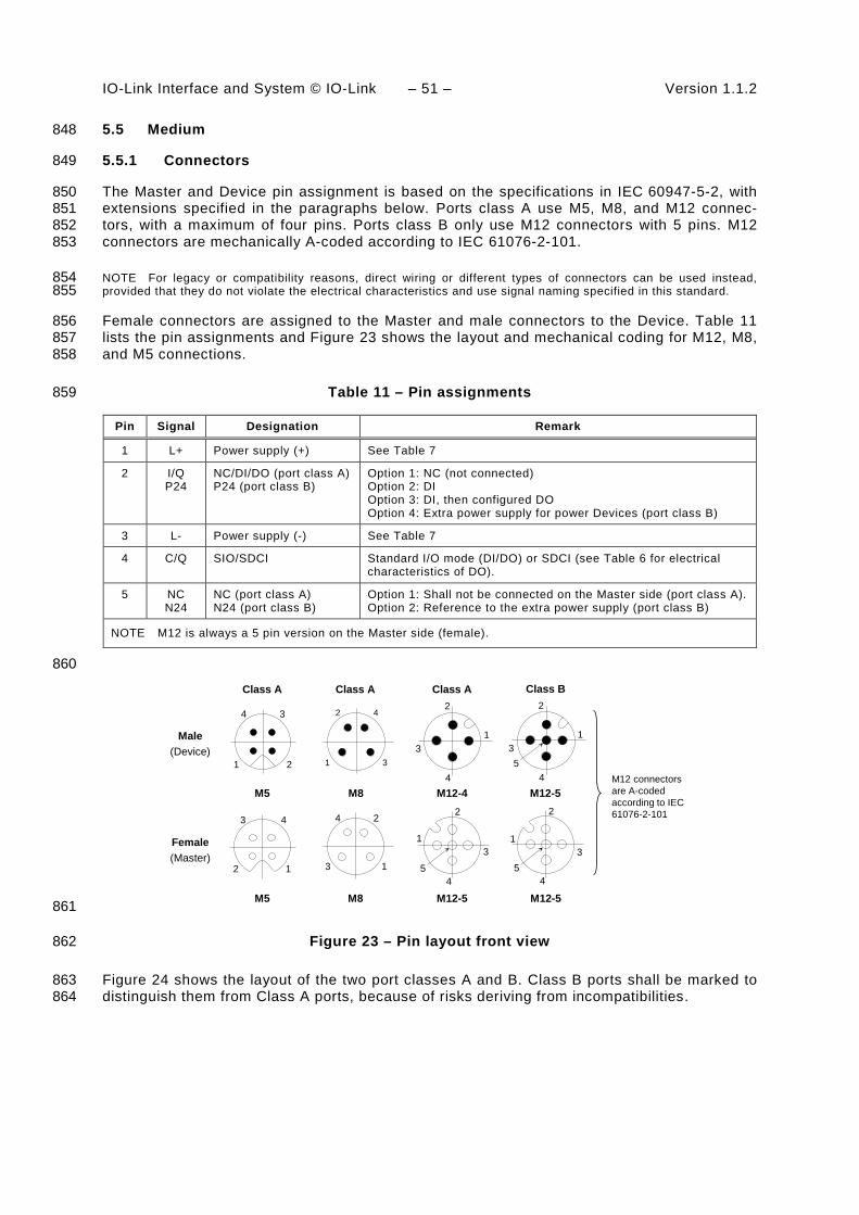
IO-Link Interface and System © IO-Link – 51 – Version 1.1.2
5.5 Medium 848
5.5.1 Connectors 849
The Master and Device pin assignment is based on the specifications in IEC 60947-5-2, with 850 extensions specified in the paragraphs below. Ports class A use M5, M8, and M12 connec-851 tors, with a maximum of four pins. Ports class B only use M12 connectors with 5 pins. M12 852 connectors are mechanically A-coded according to IEC 61076-2-101. 853
NOTE For legacy or compatibility reasons, direct wiring or different types of connectors can be used instead, 854 provided that they do not violate the electrical characteristics and use signal naming specified in this standard. 855
Female connectors are assigned to the Master and male connectors to the Device. Table 11 856 lists the pin assignments and Figure 23 shows the layout and mechanical coding for M12, M8, 857 and M5 connections. 858
Table 11 – Pin assignments 859
Pin Signal Designation Remark
1 L+ Power supply (+) See Table 7
2 I/Q P24
NC/DI/DO (port class A) P24 (port class B)
Option 1: NC (not connected) Option 2: DI Option 3: DI, then configured DO Option 4: Extra power supply for power Devices (port class B)
3 L- Power supply (-) See Table 7
4 C/Q SIO/SDCI Standard I/O mode (DI/DO) or SDCI (see Table 6 for electrical characteristics of DO).
5 NC N24
NC (port class A) N24 (port class B)
Option 1: Shall not be connected on the Master side (port class A). Option 2: Reference to the extra power supply (port class B)
NOTE M12 is always a 5 pin version on the Master side (female).
860
Male(Device)
Female(Master)
Class A Class A Class A
1
2
3
451
2
3
4
12
3 4
1
2
3
41
2
3
4
1 2
34
Class B
1
2
3
45
1
2
3
45
M12-4 M12-5
M12-5 M12-5
M12 connectors are A-coded according to IEC 61076-2-101
M8
M8
M5
M5 861
Figure 23 – Pin layout front view 862
Figure 24 shows the layout of the two port classes A and B. Class B ports shall be marked to 863 distinguish them from Class A ports, because of risks deriving from incompatibilities. 864

Version 1.1.2 – 52 – IO-Link Interface and System © IO-Link
1
2
4
3
5
1
2
4
3
5
I/Q
Power 1power supply
Port Class A (M12)
Port Class B (M12)
Power 1power supply
Power 2extrapowersupply
P24 (Act)
N24 (Act)
PIN 2:
PIN 5:PIN 4:
Option 1: NC (not connected)Option 2: DIOption 3: DI configured DONCDI; COMx; DO
Protection
PIN 2:
PIN 5:PIN 4:
P24 (extra power supply for power Devices, current is manufacturer dependent)
N24 DI; COMx; DO
C/Q
C/Q
865
Figure 24 – Class A and B port definitions 866
5.5.2 Cable 867
The transmission medium for SDCI communication is a multi-wired cable with 3 or more wires. 868 The definitions in the following paragraphs implicitly cover the static voltage definitions in 869 Table 5 and Figure 16. To ensure functional reliability, the cable properties shall comply with 870 Table 12. 871
Table 12 – Cable characteristics 872
Property Minimum Typical Maximum Unit
Length 0 n/a 20 m
Overall loop resistance RLeff n/a n/a 6,0 Ω
Effective line capacitance CLeff n/a n/a 3,0 nF (<1 MHz)
873 The loop resistance RLeff and the effective line capacitance CLeff may be measured as 874 demonstrated in Figure 25. 875
L+
L-C/Q
RLeff
CLeff
L 876
Figure 25 – Reference schematic for effective line capacitance and loop resistance 877
Table 13 shows the cable conductors and their assigned color codes. 878
Table 13 – Cable conductor assignments 879
Signal Designation Color Remark
L- Power supply (-) Bluea SDCI 3-wire connection system

IO-Link Interface and System © IO-Link – 53 – Version 1.1.2
Signal Designation Color Remark
C/Q Communication signal Blacka SDCI 3-wire connection system
L+ Power supply (+) Browna SDCI 3-wire connection system
I/Q DI or DO Whitea Optional
P24 Extra power supply (+) Any other Optional
N24 Extra power supply (-) Any other Optional
a Corresponding to IEC 60947-5-2
880
6 Standard Input and Output (SIO) 881
Figure 83 and Figure 94 demonstrate how the SIO mode allows a Device to bypass the SDCI 882 communication layers and to map the DI or DO signal directly into the data exchange mes-883 sage of the higher level fieldbus or system. Changing between the SDCI and SIO mode is 884 defined by the user configuration or implicitly by the services of the Master applications. The 885 system management takes care of the corresponding initialization or deactivation of the SDCI 886 communication layers and the physical layer (mode switch). The characteristics of the 887 interfaces for the DI and DO signals are derived from the caracteristics specified in 888 IEC 61131-2 for type 1. 889
7 Data link layer (DL) 890
7.1 General 891
The data link layers of SDCI are concerned with the delivery of messages between a Master 892 and a Device across the physical link. It uses several M-sequence ("message sequence") 893 types for different data categories. 894
A set of DL-services is available to the application layer (AL) for the exchange of Process 895 Data (PD) and On-request Data (OD). Another set of DL-services is available to system 896 management (SM) for the retrieval of Device identification parameters and the setting of state 897 machines within the DL. The DL uses PL-Services for controlling the physical layer (PL) and 898 for exchanging UART frames. The DL takes care of the error detection of messages (whether 899 internal or reported from the PL) and the appropriate remedial measures (e.g. retry). 900
The data link layers are structured due to the nature of the data categories into Process Data 901 handlers and On-request Data handlers which are in turn using a message handler to deal 902 with the requested transmission of messages. The special modes of Master ports such as 903 wake-up, COMx, and SIO (disable communication) require a dedicated DL-mode handler 904 within the Master DL. The special wake-up signal modulation requires signal detection on the 905 Device side and thus a DL-mode handler within the Device DL. Each handler comprises its 906 own state machine. 907
The data link layer is subdivided in a DL-A section with its own internal services and a DL-B 908 section with the external services. 909
The DL uses additional internal administrative calls between the handlers which are defined in 910 the "internal items" section of the associated state-transition tables. 911
Figure 26 shows an overview of the structure and the services of the Master's data link layer. 912
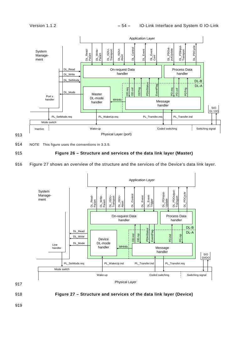
Version 1.1.2 – 54 – IO-Link Interface and System © IO-Link
MasterDL-modehandler Message
handler
DL_SetMode
DL_Mode
DL_Read
DL_Write
SystemManage-ment
Application Layer
On-request Datahandler
Process Datahandler
DL-BDL-A
PL_Transfer.req PL_Transfer.ind
PD
.req
PD
.cnf
DL_
Eve
nt
DL_
PD
Out
-pu
tUpd
ate
DL_
PD
Inpu
t-Tr
ansp
ort
DL_
Rea
d-P
aram
DL_
Writ
e-P
aram
DL_
ISD
U-
Tran
spor
t
DL_
Con
trol
DL_
PD
Cyc
le
PL_WakeUp.req
Port xhandler
Physical Layer (port)
Wake-up Switching signalCoded switchingInactive
PL_SetMode.req
OD
.req
OD
.cnf
Eve
ntFl
ag
SIODI / DO
Mode switch
PD
InS
tatu
sD
L_E
vent
Con
f
DL_
ISD
U-
Abo
rt
MHInfo
OD
Trig
PD
Trig
913
NOTE This figure uses the conventions in 3.3.5. 914
Figure 26 – Structure and services of the data link layer (Master) 915
Figure 27 shows an overview of the structure and the services of the Device's data link layer. 916
DeviceDL-modehandler Message
handler
DL_Mode
SystemManage-ment
Application Layer
On-request Datahandler
Process Datahandler
DL-BDL-A
PD
.ind
PD
.rsp
DL_
Eve
nt
DL_
PD
Inpu
t-U
pdat
e
DL_
PD
Out
put-
Tran
spor
t
DL_
Rea
d-P
aram
DL_
Writ
e-P
aram
DL_
ISD
U-
Tran
spor
t
DL_
Con
trol
DL_
PD
Cyc
le
DL_
Eve
nt-
Trig
ger
DL_Read
DL_Write
Physical Layer
PL_Transfer.ind PL_Transfer.reqPL_WakeUp.indPL_SetMode.req
Wake-up Coded switching
SIODI/DO
OD
.rsp
OD
.ind
Eve
ntFl
ag
Switching signal
Mode switch
Linehandler
PD
InS
tatu
s
DL_
ISD
U-
Abo
rt
MHInfo
917
Figure 27 – Structure and services of the data link layer (Device) 918
919

IO-Link Interface and System © IO-Link – 55 – Version 1.1.2
7.2 Data link layer services 920
7.2.1 DL-B services 921
7.2.1.1 Overview of services within Master and Device 922
This clause defines the services of the data link layer to be provided to the application layer 923 and system management via its external interfaces. Table 14 lists the assignments of Master 924 and Device to their roles as initiator or receiver for the individual DL services. Empty fields 925 indicate no availability of this service on Master or Device. 926
Table 14 – Service assignments within Master and Device 927
Service name Master Device
DL_ReadParam R I
DL_WriteParam R I
DL_ISDUTransport R I
DL_ISDUAbort R I
DL_PDOutputUpdate R
DL_PDOutputTransport I
DL_PDInputUpdate R
DL_PDInputTransport I
DL_PDCycle I I
DL_SetMode R
DL_Mode I I
DL_Event I R
DL_EventConf R
DL_EventTrigger R
DL_Control I / R R / I
DL_Read R I
DL_Write R I
Key (see 3.3.4) I Initiator of service R Receiver (responder) of service
928 See 3.3 for conventions and how to read the service descriptions in 7.2, 8.2, 9.2.2, and 9.3.2. 929
7.2.1.2 DL_ReadParam 930
The DL_ReadParam service is used by the AL to read a parameter value from the Device via 931 the page communication channel. The parameters of the service primitives are listed in Table 932 15. 933
Table 15 – DL_ReadParam 934
Parameter name .req .cnf .ind
Argument M M
Address M M
Result (+) S
Value M

Version 1.1.2 – 56 – IO-Link Interface and System © IO-Link
Parameter name .req .cnf .ind
Result (-) S
ErrorInfo M
935 Argument 936 The service-specific parameters are transmitted in the argument. 937
Address 938 This parameter contains the address of the requested Device parameter, i.e. the Device 939 parameter addresses within the page communication channel (see Table B.1). 940
Permitted values: 0 to 31 941
Result (+): 942 This selection parameter indicates that the service has been executed successfully. 943
Value 944 This parameter contains read Device parameter values. 945
Result (-): 946 This selection parameter indicates that the service failed. 947
ErrorInfo 948 This parameter contains error information. 949
Permitted values: 950 NO_COMM (no communication available), 951 STATE_CONFLICT (service unavailable within current state) 952
953
7.2.1.3 DL_WriteParam 954
The DL_WriteParam service is used by the AL to write a parameter value to the Device via 955 the page communication channel. The parameters of the service primitives are listed in Table 956 16. 957
Table 16 – DL_WriteParam 958
Parameter name .req .cnf .ind
Argument M M
Address M M
Value M M
Result (+) S
Result (-) S
ErrorInfo M
959 Argument 960 The service-specific parameters are transmitted in the argument. 961
Address 962 This parameter contains the address of the requested Device parameter, i.e. the Device 963 parameter addresses within the page communication channel. 964
Permitted values: 16 to 31, in accordance with Device parameter access rights 965
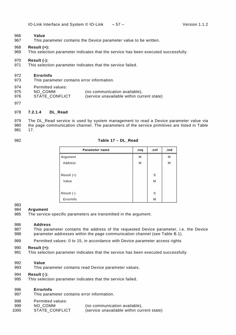
IO-Link Interface and System © IO-Link – 57 – Version 1.1.2
Value 966 This parameter contains the Device parameter value to be written. 967
Result (+): 968 This selection parameter indicates that the service has been executed successfully. 969
Result (-): 970 This selection parameter indicates that the service failed. 971
ErrorInfo 972 This parameter contains error information. 973
Permitted values: 974 NO_COMM (no communication available), 975 STATE_CONFLICT (service unavailable within current state) 976
977
7.2.1.4 DL_Read 978
The DL_Read service is used by system management to read a Device parameter value via 979 the page communication channel. The parameters of the service primitives are listed in Table 980 17. 981
Table 17 – DL_Read 982
Parameter name .req .cnf .ind
Argument M M
Address M M
Result (+) S
Value M
Result (-) S
ErrorInfo M
983 Argument 984 The service-specific parameters are transmitted in the argument. 985
Address 986 This parameter contains the address of the requested Device parameter, i.e. the Device 987 parameter addresses within the page communication channel (see Table B.1). 988
Permitted values: 0 to 15, in accordance with Device parameter access rights 989
Result (+): 990 This selection parameter indicates that the service has been executed successfully. 991
Value 992 This parameter contains read Device parameter values. 993
Result (-): 994 This selection parameter indicates that the service failed. 995
ErrorInfo 996 This parameter contains error information. 997
Permitted values: 998 NO_COMM (no communication available), 999 STATE_CONFLICT (service unavailable within current state) 1000

Version 1.1.2 – 58 – IO-Link Interface and System © IO-Link
7.2.1.5 DL_Write 1001
The DL_Write service is used by system management to write a Device parameter value to 1002 the Device via the page communication channel. The parameters of the service primitives are 1003 listed in Table 18. 1004
Table 18 – DL_Write 1005
Parameter name .req .cnf .ind
Argument M M
Address M M
Value M M
Result (+) S
Result (-) S
ErrorInfo M
1006 Argument 1007 The service-specific parameters are transmitted in the argument. 1008
Address 1009 This parameter contains the address of the requested Device parameter, i.e. the Device 1010 parameter addresses within the page communication channel. 1011
Permitted values: 0 to 15, in accordance with parameter access rights 1012
Value 1013 This parameter contains the Device parameter value to be written. 1014
Result (+): 1015 This selection parameter indicates that the service has been executed successfully. 1016
Result (-): 1017 This selection parameter indicates that the service failed. 1018
ErrorInfo 1019 This parameter contains error information. 1020
Permitted values: 1021 NO_COMM (no communication available), 1022 STATE_CONFLICT (service unavailable within current state) 1023
1024
7.2.1.6 DL_ISDUTransport 1025
The DL_ISDUTransport service is used to transport an ISDU. This service is used by the 1026 Master to send a service request from the Master application layer to the Device. It is used by 1027 the Device to send a service response to the Master from the Device application layer. The 1028 parameters of the service primitives are listed in Table 19. 1029
Table 19 – DL_ISDUTransport 1030
Parameter name .req .ind .cnf .res
Argument M M
ValueList M M

IO-Link Interface and System © IO-Link – 59 – Version 1.1.2
Parameter name .req .ind .cnf .res
Result (+) S S
Data C C
Qualifier M M
Result (-) S S
ISDUTransportErrorInfo M M
1031 Argument 1032 The service-specific parameters are transmitted in the argument. 1033
ValueList 1034 This parameter contains the relevant operating parameters 1035
Parameter type: Record 1036
Index 1037 Permitted values: 2 to 65535 (See B.2.1 for constraints) 1038 1039 Subindex 1040 Permitted values: 0 to 255 1041 1042 Data 1043 Parameter type: Octet string 1044 1045 Direction 1046 Permitted values: 1047 READ (Read operation), 1048 WRITE (Write operation) 1049 1050
Result (+): 1051 This selection parameter indicates that the service has been executed successfully. 1052
Data 1053 Parameter type: Octet string 1054 1055 Qualifier 1056 Permitted values: an I-Service Device response according to Table A.12 1057 1058 1059
Result (-): 1060 This selection parameter indicates that the service failed. 1061
ISDUTransportErrorInfo 1062 This parameter contains error information. 1063
Permitted values: 1064 NO_COMM (no communication available), 1065 STATE_CONFLICT (service unavailable within current state), 1066 ISDU_TIMEOUT (ISDU acknowledgement time elapsed, see Table 97), 1067 ISDU_NOT_SUPPORTED (ISDU not implemented), 1068 VALUE_OUT_OF_RANGE (Service parameter value violates range definitions) 1069
1070
7.2.1.7 DL_ISDUAbort 1071
The DL_ISDUAbort service aborts the current ISDU transmission. This service has no 1072 parameters. The service primitives are listed in Table 20. 1073

Version 1.1.2 – 60 – IO-Link Interface and System © IO-Link
Table 20 – DL_ISDUAbort 1074
Parameter name .req .cnf
<none>
1075
The service returns with the confirmation after abortion of the ISDU transmission. 1076
1077
7.2.1.8 DL_PDOutputUpdate 1078
The Master’s application layer uses the DL_PDOutputUpdate service to update the output 1079 data (Process Data from Master to Device) on the data link layer. The parameters of the 1080 service primitives are listed in Table 21. 1081
Table 21 – DL_PDOutputUpdate 1082
Parameter name .req .cnf
Argument M
OutputData M
Result (+) S
TransportStatus M
Result (-) S
ErrorInfo M
1083 Argument 1084 The service-specific parameters are transmitted in the argument. 1085
OutputData 1086 This parameter contains the Process Data provided by the application layer. 1087
Parameter type: Octet string 1088
Result (+): 1089 This selection parameter indicates that the service has been executed successfully. 1090
TransportStatus 1091 This parameter indicates whether the data link layer is in a state permitting data to be 1092 transferred to the communication partner(s). 1093
Permitted values: 1094 YES (data transmission permitted), 1095 NO (data transmission not permitted), 1096
Result (-): 1097 This selection parameter indicates that the service failed. 1098
ErrorInfo 1099 This parameter contains error information. 1100
Permitted values: 1101 NO_COMM (no communication available), 1102 STATE_CONFLICT (service unavailable within current state) 1103
1104

IO-Link Interface and System © IO-Link – 61 – Version 1.1.2
7.2.1.9 DL_PDOutputTransport 1105
The data link layer on the Device uses the DL_PDOutputTransport service to transfer the 1106 content of output Process Data to the application layer (from Master to Device). The 1107 parameters of the service primitives are listed in Table 22. 1108
Table 22 – DL_PDOutputTransport 1109
Parameter name .ind
Argument M
OutputData M
1110 Argument 1111 The service-specific parameters are transmitted in the argument. 1112
OutputData 1113 This parameter contains the Process Data to be transmitted to the application layer. 1114
Parameter type: Octet string 1115
1116
7.2.1.10 DL_PDInputUpdate 1117
The Device's application layer uses the DL_PDInputUpdate service to update the input data 1118 (Process Data from Device to Master) on the data link layer. The parameters of the service 1119 primitives are listed in Table 23. 1120
Table 23 – DL_PDInputUpdate 1121
Parameter name .req .cnf
Argument M
InputData M
Result (+) S
TransportStatus M
Result (-) S
ErrorInfo M
1122 Argument 1123 The service-specific parameters are transmitted in the argument. 1124
InputData 1125 This parameter contains the Process Data provided by the application layer. 1126
Result (+): 1127 This selection parameter indicates that the service has been executed successfully. 1128
TransportStatus 1129 This parameter indicates whether the data link layer is in a state permitting data to be 1130 transferred to the communication partner(s). 1131
Permitted values: 1132 YES (data transmission permitted), 1133 NO (data transmission not permitted), 1134
Result (-): 1135 This selection parameter indicates that the service failed. 1136

Version 1.1.2 – 62 – IO-Link Interface and System © IO-Link
ErrorInfo 1137 This parameter contains error information. 1138
Permitted values: 1139 NO_COMM (no communication available), 1140 STATE_CONFLICT (service unavailable within current state) 1141
1142
7.2.1.11 DL_PDInputTransport 1143
The data link layer on the Master uses the DL_PDInputTransport service to transfer the 1144 content of input data (Process Data from Device to Master) to the application layer. The 1145 parameters of the service primitives are listed in Table 24. 1146
Table 24 – DL_PDInputTransport 1147
Parameter name .ind
Argument M
InputData M
1148 Argument 1149 The service-specific parameters are transmitted in the argument. 1150
InputData 1151 This parameter contains the Process Data to be transmitted to the application layer. 1152
Parameter type: Octet string 1153
1154
7.2.1.12 DL_PDCycle 1155
The data link layer uses the DL_PDCycle service to indicate the end of a Process Data cycle 1156 to the application layer. This service has no parameters. The service primitives are listed in 1157 Table 25. 1158
Table 25 – DL_PDCycle 1159
Parameter name .ind
<none>
1160
7.2.1.13 DL_SetMode 1161
The DL_SetMode service is used by system management to set up the data link layer's state 1162 machines and to send the characteristic values required for operation to the data link layer. 1163 The parameters of the service primitives are listed in Table 26. 1164
Table 26 – DL_SetMode 1165
Parameter name .req .cnf
Argument M
Mode M
ValueList U
Result (+) S

IO-Link Interface and System © IO-Link – 63 – Version 1.1.2
Parameter name .req .cnf
Result (-) S
ErrorInfo M
1166 Argument 1167 The service-specific parameters are transmitted in the argument. 1168
Mode 1169 This parameter indicates the requested mode of the Master's DL on an individual port. 1170
Permitted values: 1171 INACTIVE (handler shall change to the INACTIVE state), 1172 STARTUP (handler shall change to STARTUP state), 1173 PREOPERATE (handler shall change to PREOPERATE state), 1174 OPERATE (handler shall change to OPERATE state) 1175
ValueList 1176 This parameter contains the relevant operating parameters. 1177
Data structure: record 1178
M-sequenceTime: (to be propagated to message handler) 1179 1180 M-sequenceType: (to be propagated to message handler) 1181 Permitted values: 1182 TYPE_0, 1183 TYPE_1_1, TYPE_1_2, TYPE_1_V, 1184 TYPE_2_1, TYPE_2_2, TYPE_2_3, TYPE_2_4, TYPE_2_5, TYPE_2_6, TYPE_2_V 1185 (TYPE_1_1 forces interleave mode of Process and On-request Data transmission, 1186 see 7.3.4.2) 1187 PDInputLength: (to be propagated to message handler) 1188 1189 PDOutputLength: (to be propagated to message handler) 1190 1191 OnReqDataLengthPerMessage: (to be propagated to message handler) 1192 1193
Result (+): 1194 This selection parameter indicates that the service has been executed successfully. 1195
Result (-): 1196 This selection parameter indicates that the service failed. 1197
ErrorInfo 1198 This parameter contains error information. 1199
Permitted values: 1200 STATE_CONFLICT (service unavailable within current state), 1201 PARAMETER_CONFLICT (consistency of parameter set violated) 1202
1203
7.2.1.14 DL_Mode 1204
The DL uses the DL_Mode service to report to system management that a certain operating 1205 status has been reached. The parameters of the service primitives are listed in Table 27. 1206
Table 27 – DL_Mode 1207
Parameter name .ind
Argument M
RealMode M

Version 1.1.2 – 64 – IO-Link Interface and System © IO-Link
1208 Argument 1209 The service-specific parameters are transmitted in the argument. 1210
RealMode 1211 This parameter indicates the status of the DL-mode handler. 1212
Permitted values: 1213 INACTIVE (Handler changed to the INACTIVE state) 1214 COM1 (COM1 mode established) 1215 COM2 (COM2 mode established) 1216 COM3 (COM3 mode established) 1217 COMLOST (Lost communication) 1218 ESTABCOM (Handler changed to the EstablishCom state) 1219 STARTUP (Handler changed to the STARTUP state) 1220 PREOPERATE (Handler changed to the PREOPERATE state) 1221 OPERATE (Handler changed to the OPERATE state) 1222
1223
7.2.1.15 DL_Event 1224
The service DL_Event indicates a pending status or error information. The cause for an Event 1225 is located in a Device and the Device application triggers the Event transfer. The parameters 1226 of the service primitives are listed in Table 28. 1227
Table 28 – DL_Event 1228
Parameter name .req .ind
Argument M M
Instance M M
Type M M
Mode M M
EventCode M M
EventsLeft M
1229 Argument 1230 The service-specific parameters are transmitted in the argument. 1231
Instance 1232 This parameter indicates the Event source. 1233
Permitted values: Application (see Table A.17) 1234
Type 1235 This parameter indicates the Event category. 1236
Permitted values: ERROR, WARNING, NOTIFICATION (see Table A.19) 1237
Mode 1238 This parameter indicates the Event mode. 1239
Permitted values: SINGLESHOT, APPEARS, DISAPPEARS (see Table A.20) 1240
EventCode 1241 This parameter contains a code identifying a certain Event (see Table D.1). 1242
Parameter type: 16 bit unsigned integer 1243
EventsLeft 1244 This parameter indicates the number of unprocessed Events. 1245

IO-Link Interface and System © IO-Link – 65 – Version 1.1.2
1246
7.2.1.16 DL_EventConf 1247
The DL_EventConf service confirms the transmitted Events via the Event handler. This 1248 service has no parameters. The service primitives are listed in Table 29. 1249
Table 29 – DL_EventConf 1250
Parameter name .req .cnf
<none>
1251
7.2.1.17 DL_EventTrigger 1252
The DL_EventTrigger request starts the Event signaling (see Event flag in Figure A.3) and 1253 freezes the Event memory within the DL. The confirmation is returned after the activated 1254 Events have been processed. Additional DL_EventTrigger requests are ignored until the 1255 previous one has been confirmed (see 7.3.8, 8.3.3 and Figure 64). This service has no 1256 parameters. The service primitives are listed in Table 30. 1257
Table 30 – DL_EventTrigger 1258
Parameter name .req .cnf
<none>
1259
7.2.1.18 DL_Control 1260
The Master uses the DL_Control service to convey control information via the 1261 MasterCommand mechanism to the corresponding technology specific Device application and 1262 to get control information via the PD status flag mechanism (see A.1.5) and the PDInStatus 1263 service (see 7.2.2.5). The parameters of the service primitives are listed in Table 31. 1264
Table 31 – DL_Control 1265
Parameter name .req .ind
Argument M M
ControlCode M M(=)
1266 Argument 1267 The service-specific parameters are transmitted in the argument. 1268
ControlCode 1269 This parameter indicates the qualifier status of the Process Data (PD) 1270
Permitted values: 1271 VALID (Input Process Data valid; see 7.2.2.5, 8.2.2.12) 1272 INVALID (Input Process Data invalid) 1273 PDOUTVALID (Output Process Data valid; see 7.3.7.1) 1274 PDOUTINVALID (Output Process Data invalid or missing) 1275
1276

Version 1.1.2 – 66 – IO-Link Interface and System © IO-Link
7.2.2 DL-A services 1277
7.2.2.1 Overview 1278
According to 7.1 the data link layer is split into the upper layer DL-B and the lower layer DL-A. 1279 The layer DL-A comprises the message handler as shown in Figure 26 and Figure 27. 1280
The Master message handler encodes commands and data into messages and sends these to 1281 the connected Device via the physical layer. It receives messages from the Device via the 1282 physical layer and forwards their content to the corresponding handlers in the form of a 1283 confirmation. When the "Event flag" is set in a Device message (see A.1.5), the Master 1284 message handler invokes an EventFlag service to prompt the Event handler. 1285
The Master message handler shall employ a retry strategy following a corrupted message, i.e. 1286 upon receiving an incorrect checksum from a Device, or no checksum at all. In these cases 1287 the Master shall repeat the Master message two times (see Table 97). If the retries are not 1288 successful, a negative confirmation shall be provided and the Master shall re-initiate the 1289 communication via the Port-x handler beginning with a wake-up. 1290
After a start-up phase the message handler performs cyclic operation with the M-sequence 1291 type and cycle time provided by the DL_SetMode service. 1292
Table 32 lists the assignment of Master and Device to their roles as initiator (I) or receiver (R) 1293 in the context of the execution of their individual DL-A services. 1294
Table 32 – DL-A services within Master and Device 1295
Service name Master Device
OD R I
PD R I
EventFlag I R
PDInStatus I R
MHInfo I I
ODTrig I
PDTrig I
1296
7.2.2.2 OD 1297
The OD service is used to set up the On-request Data for the next message to be sent. In 1298 turn, the confirmation of the service contains the data from the receiver. The parameters of 1299 the service primitives are listed in Table 33. 1300
Table 33 – OD 1301
Parameter name .req .ind .rsp .cnf
Argument M M
RWDirection M M
ComChannel M M
AddressCtrl M M
Length M M
Data C C

IO-Link Interface and System © IO-Link – 67 – Version 1.1.2
Parameter name .req .ind .rsp .cnf
Result (+) S S
Data C C(=)
Length M M
Result (-) S S
ErrorInfo M M(=)
1302 Argument 1303 The service-specific parameters are transmitted in the argument. 1304
RWDirection 1305 This parameter indicates the read or write direction. 1306
Permitted values: 1307 READ (Read operation), 1308 WRITE (Write operation) 1309
ComChannel 1310 This parameter indicates the selected communication channel for the transmission. 1311
Permitted values: DIAGNOSIS, PAGE, ISDU (see Table A.1) 1312
AddressCtrl 1313 This parameter contains the address or flow control value (see A.1.2). 1314
Permitted values: 0 to 31 1315
Length 1316 This parameter contains the length of data to transmit. 1317
Permitted values: 0 to 32 1318
Data 1319 This parameter contains the data to transmit. 1320
Data type: Octet string 1321
Result (+): 1322 This selection parameter indicates that the service has been executed successfully. 1323
Data 1324 This parameter contains the read data values. 1325
Length 1326 This parameter contains the length of the received data package. 1327
Permitted values: 0 to 32 1328
Result (-): 1329 This selection parameter indicates that the service failed. 1330
ErrorInfo 1331 This parameter contains error information. 1332
Permitted values: 1333 NO_COMM (no communication available), 1334 STATE_CONFLICT (service unavailable within current state) 1335
1336

Version 1.1.2 – 68 – IO-Link Interface and System © IO-Link
7.2.2.3 PD 1337
The PD service is used to setup the Process Data to be sent through the process 1338 communication channel. The confirmation of the service contains the data from the receiver. 1339 The parameters of the service primitives are listed in Table 34. 1340
Table 34 – PD 1341
Parameter name .req .ind .rsp .cnf
Argument M M
PDInAddress C C(=)
PDInLength C C(=)
PDOut C C(=)
PDOutAddress C C(=)
PDOutLength C C(=)
Result (+) S S
PDIn C C(=)
Result (-) S S
ErrorInfo M M(=)
1342 Argument 1343 The service-specific parameters are transmitted in the argument. 1344
PDInAddress 1345 This parameter contains the address of the requested input Process Data (see 7.3.4.2). 1346
PDInLength 1347 This parameter contains the length of the requested input Process Data. 1348
Permitted values: 0 to 32 1349
PDOut 1350 This parameter contains the Process Data to be transferred from Master to Device. 1351
Data type: Octet string 1352
PDOutAddress 1353 This parameter contains the address of the transmitted output Process Data (see 7.3.4.2). 1354
PDOutLength 1355 This parameter contains the length of the transmitted output Process Data. 1356
Permitted values: 0 to 32 1357
Result (+) 1358
This selection parameter indicates that the service has been executed successfully. 1359
PDIn 1360 This parameter contains the Process Data to be transferred from Device to Master. 1361
Data type: Octet string 1362
Result (-) 1363
This selection parameter indicates that the service failed. 1364
ErrorInfo 1365

IO-Link Interface and System © IO-Link – 69 – Version 1.1.2
This parameter contains error information. 1366
Permitted values: 1367 NO_COMM (no communication available), 1368 STATE_CONFLICT (service unavailable within current state) 1369
1370
7.2.2.4 EventFlag 1371
The EventFlag service sets or signals the status of the "Event flag" (see A.1.5) during cyclic 1372 communication. The parameters of the service primitives are listed in Table 35. 1373
Table 35 – EventFlag 1374
Parameter name .ind .req
Argument
Flag M M
1375 Argument 1376 The service-specific parameters are transmitted in the argument. 1377
Flag 1378 This parameter contains the value of the "Event flag". 1379
Permitted values: 1380 TRUE ("Event flag" = 1) 1381 FALSE ("Event flag" = 0) 1382 1383
7.2.2.5 PDInStatus 1384
The service PDInStatus sets and signals the validity qualifier of the input Process Data. The 1385 parameters of the service primitives are listed in Table 36. 1386
Table 36 – PDInStatus 1387
Parameter name .req .ind
Argument
Status M M
1388 Argument 1389 The service-specific parameters are transmitted in the argument. 1390
Status 1391 This parameter contains the validity indication of the transmitted input Process Data. 1392
Permitted values: 1393 VALID (Input Process Data valid based on PD status flag (see A.1.5); see 7.2.1.18) 1394 INVALID (Input Process Data invalid) 1395
1396
7.2.2.6 MHInfo 1397
The service MHInfo signals an exceptional operation within the message handler. The 1398 parameters of the service are listed in Table 37. 1399

Version 1.1.2 – 70 – IO-Link Interface and System © IO-Link
Table 37 – MHInfo 1400
Parameter name .ind
Argument
MHInfo M
1401 Argument 1402 The service-specific parameters are transmitted in the argument. 1403
MHInfo 1404 This parameter contains the exception indication of the message handler. 1405
Permitted values: 1406 COMLOST (lost communication), 1407 ILLEGAL_MESSAGETYPE (unexpected M-sequence type detected) 1408 CHECKSUM_MISMATCH (Checksum error detected) 1409
1410
7.2.2.7 ODTrig 1411
The service ODTrig is only available on the Master. The service triggers the On-request Data 1412 handler and the ISDU, Command, or Event handler currently in charge to provide the On-1413 request Data (via the OD service) for the next Master message. The parameters of the service 1414 are listed in Table 38. 1415
Table 38 – ODTrig 1416
Parameter name .ind
Argument
DataLength M
1417 Argument 1418 The service-specific parameters are transmitted in the argument. 1419
DataLength 1420 This parameter contains the available space for On-request Data (OD) per message. 1421
1422
7.2.2.8 PDTrig 1423
The service PDTrig is only available on the Master. The service triggers the Process Data 1424 handler to provide the Process Data (PD) for the next Master message. 1425
The parameters of the service are listed in Table 39. 1426
Table 39 – PDTrig 1427
Parameter name .ind
Argument
DataLength M
1428 Argument 1429 The service-specific parameters are transmitted in the argument. 1430
DataLength 1431 This parameter contains the available space for Process Data (PD) per message. 1432

IO-Link Interface and System © IO-Link – 71 – Version 1.1.2
7.3 Data link layer protocol 1433
7.3.1 Overview 1434
Figure 26 and Figure 27 are showing the structure of the data link layer and its components; a 1435 DL-mode handler, a message handler, a Process Data handler, and an On-request Data 1436 handler to provide the specified services. Subclauses 7.3.2 to 7.3.8 define the behaviour 1437 (dynamics) of these handlers by means of UML state machines and transition tables. 1438
The On-request Data handler supports three independent types of data: ISDU, command and 1439 Event. Therefore, three additional state machines are working together with the On-request 1440 Data handler state machine as shown in Figure 28. Supplementary sequence or activity 1441 diagrams are demonstrating certain use cases. See IEC/TR 62390 and ISO/IEC 19505. 1442
The elements each handler is dealing with, such as messages, wake-up procedures, 1443 interleave mode, ISDU (Indexed Service Data Units), and Events are defined within the 1444 context of the respective handler. 1445
State machine:Message handlerState machine:
Message handlerState machine:
DL-mode handlerState machine:
DL-mode handler
State machine:On-request Data handler
State machine:On-request Data handler
State machine:ISDU handler
State machine:ISDU handler
State machine:Command handler
State machine:Command handler
State machine:Event handlerState machine:Event handler
State machine:Process Data handler
State machine:Process Data handler
1446
Figure 28 – State machines of the data link layer 1447
7.3.2 DL-mode handler 1448
7.3.2.1 General 1449
The Master DL-mode handler shown in Figure 26 is responsible to setup the SDCI 1450 communication using services of the Physical Layer (PL) and internal administrative calls to 1451 control and monitor the message handler as well as the states of other handlers. 1452
The Device DL-mode handler shown in Figure 27 is responsible to detect a wake-up request 1453 and to establish communication. It receives MasterCommands to synchronize with the Master 1454 DL-mode handler states STARTUP, PREOPERATE, and OPERATE and manages the 1455 activation and de-activation of handlers as appropriate. 1456
7.3.2.2 Wake-up procedures and Device conformity rules 1457
System management triggers the following actions on the data link layer with the help of the 1458 DL_SetMode service (requested mode = STARTUP). 1459
The Master DL-mode handler tries to establish communication via a wake-up request 1460 (PL_WakeUp.req) followed by a test message with M-sequence TYPE_0 (read 1461 "MinCycleTime") according to the sequence shown in Figure 29. 1462

Version 1.1.2 – 72 – IO-Link Interface and System © IO-Link
TREN
TDMT TDMT
1 2 3
SIO
4COM3 COM2 COM1
Masterstart-up
Devicestart-up
WURQ
Master
Device
TDMT
1463
Figure 29 – Example of an attempt to establish communication 1464
After the wake-up request (WURQ), specified in 5.3.3.3, the DL-mode handler requests the 1465 message handler to send the first test message after a time TREN (see Table 9) and TDMT 1466 (see Table 40). The specified transmission rates of COM1, COM2, and COM3 are used in 1467 descending order until a response is obtained, as shown in the example of Figure 29: 1468
Step : Master message with transmission rate of COM3 (see Table 8). 1469 Step : Master message with transmission rate of COM2 (see Table 8). 1470 Step : Master message with transmission rate of COM1 (see Table 8). 1471 Step : Device response message with transmission rate of COM1. 1472
Before initiating a (new) message, the DL-mode handler shall wait at least for a time of TDMT. 1473 TDMT is specified in Table 40. 1474
The following conformity rule applies for Devices regarding support of transmission rates: 1475
• a Device shall support only one of the transmission rates of COM1, COM2, or COM3. 1476
If an attempt to establish communication fails, the Master DL-mode handler shall not start a 1477 new retry wake-up procedure until after a time TDWU as shown in Figure 30 and specified in 1478 Table 40. 1479
SIO
COM3 COM2 COM1
No response
WURQ
Master
Device
WURQ
TDWU 1480
Figure 30 – Failed attempt to establish communication 1481
The Master shall make up to nWU+1 successive wake-up requests as shown in Figure 31. If 1482 this initial wake-up retry sequence fails, the Device shall reset its C/Q line to SIO mode after a 1483 time TDSIO (TDSIO is retrigged in the Device after each detected WURQ). The Master shall not 1484 trigger a new wake-up retry sequence until after a time TSD. 1485

IO-Link Interface and System © IO-Link – 73 – Version 1.1.2
SIO
Master
TSD
TDSIO
Wake-up retry sequence
TDSIO
TDSIO
Device
1486
Figure 31 – Retry strategy to establish communication 1487
The DL of the Master shall request the PL to go to SIO mode after a failed wake-up retry 1488 sequence. 1489
The values for the timings of the wake-up procedures and retries are specified in Table 9 and 1490 Table 40. They are defined from a Master's point of view. 1491
Table 40 – Wake-up procedure and retry characteristics 1492
Property Designation Minimum Typical Maximum Unit Remark
TDMT Master message delay
27 n/a 37 TBIT Bit time of subsequent data transmission rate
TDSIO Standard IO delay
60 n/a 300 ms After TDSIO the Device falls back to SIO mode (if supported)
TDWU Wake-up retry delay
30 n/a 50 ms After TDWU the Master repeats the wake-up request
nWU Wake-up retry count
2 2 2 Number of wake-up request retries
TSD Device detection time
0,5 n/a 1 s Time between 2 wake-up request sequences. (See NOTE)
NOTE Characteristic of the Master.
1493 The Master’s data link layer shall stop the establishing communication procedure once it finds 1494 a communicating Device, and shall report the detected COMx-Mode to system management 1495 using a DL_Mode indication. If the procedure fails, a corresponding error is reported using the 1496 same service. 1497
7.3.2.3 Fallback procedure 1498
System management induces the following actions on the data link layer with the help of the 1499 DL_SetMode service (mode = INACTIVE): 1500
• A MasterCommand "Fallback" (see Table B.2) forces the Device to change to the SIO 1501 mode. 1502
• The Device shall accomplish the transition to the SIO mode after 3 MasterCycleTimes 1503 and/or within 500 ms after the MasterCommand "Fallback". This allows for possible retries 1504 if the MasterCommand failed indicated through a negative Device response. 1505
Figure 32 shows the fallback procedure and its retry and timing constraints. 1506

Version 1.1.2 – 74 – IO-Link Interface and System © IO-Link
Master
TFBD
MasterCommand "Fallback"
SIO
Device
MasterCycleTime
Possible retries
1507
Figure 32 – Fallback procedure 1508
Table 41 specifies the fallback timing characteristics. See A.2.6 for details. 1509
Table 41 – Fallback timing characteristics 1510
Property Designation Minimum Typical Maximum Unit Remark
TFBD Fallback delay
3 MasterCycle-Times (OPERATE)
or
3 Tinitcyc (PREOPERATE)
n/a 500 ms After a time TFBD the Device shall be switched to SIO mode (see Figure 32)
1511
7.3.2.4 State machine of the Master DL-mode handler 1512
Figure 33 shows the state machine of the Master DL-mode handler. 1513
Idle_0
/Initialization
DL_SetMode_STARTUP/T1
EstablishCom_1
Submachine 1"WakeUp"
enex_3enex_2enex_1
enex_4
[Retry = 3]/T5DL_SetMode_STARTUP/
T1
[Retry = 3]/T5
Startup_2
[Response COM3]/T2
[Response COM2]/T3
[Response COM1]/T4
[Response COM3]/T2
[Response COM2]/T3
[Response COM1]/T4
DL_SetMode_STARTUP/T7
PreOperate_3
DL_SetMode_PREOPERATE/T6
MHInfo_COMLOST/T9
DL_SetMode_INACTIVE/T8
DL_SetMode_STARTUP/T7
DL_SetMode_PREOPERATE/T6
MHInfo_COMLOST/T9
DL_SetMode_INACTIVE/T8
DL_SetMode_OPERATE/T10
Operate_4
DL_SetMode_OPERATE/T10
DL_SetMode_OPERATE/T11
DL_SetMode_STARTUP/T12
MHInfo_COMLOST/T14
DL_SetMode_INACTIVE/T13
DL_SetMode_OPERATE/T11
DL_SetMode_STARTUP/T12
MHInfo_COMLOST/T14
DL_SetMode_INACTIVE/T13
1514
Figure 33 – State machine of the Master DL-mode handler 1515

IO-Link Interface and System © IO-Link – 75 – Version 1.1.2
NOTE The conventions of the UML diagram types are defined in 3.3.7. 1516
After reception of the service DL_SetMode_STARTUP from system management, the DL-1517 mode handler shall first create a wake-up current pulse via the PL_WakeUp service and then 1518 establish communication. This procedure is specified in submachine 1 in Figure 34. 1519
The purpose of state "Startup_2" is to check a Device's identity via the data of the Direct 1520 Parameter page (see Figure 5). In state "PreOperate_3", the Master assigns parameters to 1521 the Device using ISDUs. Cyclic exchange of Process Data is performed in state "Operate". 1522 Within this state additional On-request Data such as ISDUs, commands, and Events can be 1523 transmitted using appropriate M-sequence types (see Figure 37). 1524
In state PreOperate_3 and Operate_4 different sets of handlers within the Master are 1525 activated. 1526
EstablishCom_1
WURQ_5
ComRequestCOM3_6
tm(Tdmt)/T15
ComRequestCOM2_7
tm(Tdmt)[No Response]/T16
ComRequestCOM1_8
tm(Tdmt)[No Response]/T17
Retry_9
tm(Tdmt)[No Response]/T18
tm(Tdwu)[Retries < 3]/T19
enex_3
[Response COM1]/T4
enex_2
[Response COM2]/T3
enex_1
[Response COM3]/T2
enex_4
[Retry =3]/T5
tm(Tdmt)/T15
tm(Tdmt)[No Response]/T16
tm(Tdmt)[No Response]/T17
tm(Tdmt)[No Response]/T18
tm(Tdwu)[Retries < 3]/T19
[Response COM1]/T4
[Response COM2]/T3
[Response COM3]/T2
[Retry =3]/T5
1527
Figure 34 – Submachine 1 to establish communication 1528
Table 42 shows the state transition tables of the Master DL-mode handler. 1529
Table 42 – State transition tables of the Master DL-mode handler 1530
STATE NAME STATE DESCRIPTION
Idle_0 Waiting on wakeup request from System Management (SM): DL_SetMode (STARTUP)
EstablishComm_1 Perform wakeup procedure (submachine 1)
Startup_2 System Management uses the STARTUP state for Device identification, check, and communication configuration (see Figure 69)
Preoperate_3 On-request Data exchange (parameter, commands, Events) without Process Data

Version 1.1.2 – 76 – IO-Link Interface and System © IO-Link
STATE NAME STATE DESCRIPTION
Operate_4 Process Data and On-request Data exchange (parameter, commands, Events)
SM: WURQ_5 Create wakeup current pulse: Invoke service PL-Wake-Up (see Figure 11 and 5.3.3.3) and wait TDMT (see Table 40).
SM: ComRequestCOM3_6 Try test message with transmission rate of COM3 via the message handler: Call MH_Conf_COMx (see Figure 38) and wait TDMT (see Table 40).
SM: ComRequestCOM2_7 Try test message with transmission rate of COM2 via the message handler: Call MH_Conf_COMx (see Figure 38) and wait TDMT (see Table 40).
SM: ComRequestCOM1_8 Try test message with transmission rate of COM1 via the message handler: Call MH_Conf_COMx (see Figure 38) and wait TDMT (see Table 40).
SM: Retry_9 Check number of Retries 1531
TRANSITION SOURCE STATE
TARGET STATE
ACTION
T1 0 1 Set Retry = 0.
T2 1 2 Transmission rate of COM3 successful. Message handler activated and configured to COM3 (see Figure 38, Transition T2). Activate command handler (call CH_Conf_ACTIVE in Figure 51). Return DL_Mode.ind (STARTUP) and DL_Mode.ind (COM3) to SM.
T3 1 2 Transmission rate of COM2 successful. Message handler activated and configured to COM2 (see Figure 38, Transition T2). Activate command handler (call CH_Conf_ACTIVE in Figure 51). Return DL_Mode.ind (STARTUP) and DL_Mode.ind (COM2) to SM.
T4 1 2 Transmission rate of COM1 successful. Message handler activated and configured to COM1 (see Figure 38, Transition T2). Activate command handler (call CH_Conf_ACTIVE in Figure 51). Return DL_Mode.ind (STARTUP) and DL_Mode.ind (COM1) to SM.
T5 1 0 Return DL_Mode.ind (INACTIVE) to SM.
T6 2 3 SM requested the PREOPERATE state. Activate On-request Data (call OH_Conf_ACTIVE in Figure 46), ISDU (call IH_Conf_ACTIVE in Figure 49), and Event handler (call EH_Conf_ACTIVE in Figure 53). Change message handler state to PREOPERATE (call MH_Conf_PREOPERATE in Figure 38). Return DL_Mode.ind (PREOPERATE) to SM.
T7 3 2 SM requested the STARTUP state. Change message handler state to STARTUP (call MH_Conf_STARTUP in Figure 38). Deactivate On-request Data (call OH_Conf_INACTIVE in Figure 46), ISDU (call IH_Conf_INACTIVE in Figure 49), command (call CH_Conf_INACTIVE in Figure 51) and Event handler (call EH_Conf_INACTIVE in Figure 53). Return DL_Mode.ind (STARTUP) to SM.
T8 3 0 SM requested the SIO mode. Deactivate all handlers (call xx_Conf_INACTIVE). Return DL_Mode.ind (INACTIVE) to SM. See 7.3.2.3.
T9 3 0 Message handler informs about lost communication via the DL-A service MHInfo (COMLOST). Deactivate all handlers (call xx_Conf_INACTIVE). Return DL_Mode.ind (COMLOST) to SM.
T10 3 4 SM requested the OPERATE state. Activate the Process Data handler (call PD_Conf_SINGLE if M-sequence type = TYPE_2_x, or PD_Conf_INTERLEAVE if M-sequence type = TYPE_1_1 in Figure 44). Change message handler state to OPERATE (call MH_Conf_OPERATE in Figure 38). Return DL_Mode.ind (OPERATE) to SM.
T11 2 4 SM requested the OPERATE state. Activate the Process Data handler (call PD_Conf_SINGLE or PD_Conf_INTERLEAVE in Figure 44 according to the Master port configuration). Activate On-request Data (call OH_Conf_ACTIVE in Figure 46), ISDU (call IH_Conf_ACTIVE in Figure 49), and Event handler (call EH_Conf_ACTIVE in Figure 53). Change message handler state to OPERATE (call MH_Conf_OPERATE in Figure 38). Return DL_Mode.ind (OPERATE) to SM.
T12 4 2 SM requested the STARTUP state. Change message handler state to STARTUP (call MH_Conf_STARTUP in Figure 38). Deactivate Process Data (call PD_Conf_INACTIVE in Figure 44), On-request Data (call OH_Conf_INACTIVE in Figure 46), ISDU (call IH_Conf_INACTIVE in Figure 49), and Event handler (call EH_Conf_INACTIVE in Figure 53). Return DL_Mode.ind (STARTUP) to SM.

IO-Link Interface and System © IO-Link – 77 – Version 1.1.2
TRANSITION SOURCE STATE
TARGET STATE
ACTION
T13 4 0 SM requested the SIO state. Deactivate all handlers (call xx_Conf_INACTIVE). Return DL_Mode.ind (INACTIVE) to SM. See 7.3.2.3.
T14 4 0 Message handler informs about lost communication via the DL-A service MHInfo (COMLOST). Deactivate all handlers (call xx_Conf_INACTIVE). Return DL_Mode.ind (COMLOST) to SM.
T15 5 6 Set transmission rate of COM3 mode.
T16 6 7 Set transmission rate of COM2 mode.
T17 7 8 Set transmission rate of COM1 mode.
T18 8 9 Increment Retry
T19 9 5 - 1532
INTERNAL ITEMS TYPE DEFINITION
MH_Conf_COMx Call This call causes the message handler to send a message with the requested transmission rate of COMx and with M-sequence TYPE_0 (see Table 44).
MH_Conf_STARTUP Call This call causes the message handler to switch to the STARTUP state (see Figure 38)
MH_Conf_PREOPERATE Call This call causes the message handler to switch to the PREOPERATE state (see Figure 38)
MH_Conf_OPERATE Call This call causes the message handler to switch to the OPERATE state (see Figure 38)
xx_Conf_ACTIVE Call This call activates the respective handler. xx is substitute for MH (message handler), OH (On-request Data handler), IH (ISDU handler), CH (Command handler), and/or EH (Event handler)
xx_Conf_INACTIVE Call This call deactivates the message handler. xx is substitute for MH (message handler), OH (On-request Data handler), IH (ISDU handler), CH (Command handler), and/or EH (Eventhandler)
Retry Variable Number of retries to establish communication
1533
7.3.2.5 State machine of the Device DL-mode handler 1534
Figure 35 shows the state machine of the Device DL-mode handler. In state PreOperate_3 1535 and Operate_4 different sets of handlers within the Device are activated. 1536

Version 1.1.2 – 78 – IO-Link Interface and System © IO-Link
Idle_0
/Initialization
PL_WakeUp/T1
EstablishCom_1
PL_WakeUp/T1
tm(Tdsio)/T10tm(Tdsio)/T10
[Successful COMx]/T2
Startup_2
[Successful COMx]/T2
[MCmd_PREOPERATE]/T3
PreOperate_3
[MCmd_PREOPERATE]/T3
[MCmd_STARTUP]/T6
[MCmd_FALLBACK]/T8
MHInfo_ILLEGAL_MESSAGETYPE/T12
[MCmd_STARTUP]/T6
[MCmd_FALLBACK]/T8
MHInfo_ILLEGAL_MESSAGETYPE/T12
[MCmd_OPERATE]/T4
Operate_4
[MCmd_OPERATE]/T4
[MCmd_OPERATE]/T5
[MCmd_STARTUP]/T7
[MCmd_FALLBACK]/T9
MHInfo_ILLEGAL_MESSAGETYPE/T11
[MCmd_OPERATE]/T5
[MCmd_STARTUP]/T7
[MCmd_FALLBACK]/T9
MHInfo_ILLEGAL_MESSAGETYPE/T11
1537
Figure 35 – State machine of the Device DL-mode handler 1538
The Master uses MasterCommands (see Table 42) to change the Device to SIO, STARTUP, 1539 PREOPERATE, and OPERATE states. Whenever the message handler detects illegal 1540 (unexpected) M-sequence types, it will cause the DL-mode handler to change to the 1541 STARTUP state and to indicate this state to its system mangement (see 9.3.3.2) for the 1542 purpose of synchronization of Master and Device. 1543
Table 43 shows the state transition tables of the Device DL-mode handler. 1544
Table 43 – State transition tables of the Device DL-mode handler 1545
STATE NAME STATE DESCRIPTION
Idle_0 Waiting on a detected wakeup current pulse (PL_WakeUp.ind).
EstablishComm_1 Message handler activated and waiting for the COMx test messages (see Table 42)
Startup_2 Compatibility check (see 9.2.3.3)
Preoperate_3 On-request Data exchange (parameter, commands, Events) without Process Data
Operate_4 Process Data (PD) and On-request Data exchange (parameter, commands, Events) 1546
TRANSITION SOURCE STATE
TARGET STATE
ACTION
T1 0 1 Wakeup current pulse detected. Activate message handler (call MH_Conf_ACTIVE in Figure 42). Indicate state via service DL_Mode.ind (ESTABCOM) to SM.
T2 1 2 One out of the three transmission rates of COM3, COM2, or COM1 mode established. Activate On-request Data (call OH_Conf_ACTIVE in Figure 47) and command handler (call CH_Conf_ACTIVE in Figure 52). Indicate state via service DL_Mode.ind (COM1, COM2, or COM3) to SM.
T3 2 3 Device command handler received MasterCommand (MCmd_PREOPERATE). Activate ISDU (call IH_Conf_ACTIVE in Figure 50) and Event handler (call EH_Conf_ACTIVE in Figure 54). Indicate state via service DL_Mode.ind (PREOPERATE) to SM.
T4 3 4 Device command handler received MasterCommand (MCmd_OPERATE). Activate Process Data handler (call PD_Conf_ACTIVE in Figure 45).

IO-Link Interface and System © IO-Link – 79 – Version 1.1.2
TRANSITION SOURCE STATE
TARGET STATE
ACTION
Indicate state via service DL_Mode.ind (OPERATE) to SM.
T5 2 4 Device command handler received MasterCommand (MCmd_OPERATE). Activate Process Data handler (call PD_Conf_ACTIVE in Figure 45), ISDU (call IH_Conf_ACTIVE in Figure 50), and Event handler (call EH_Conf_ACTIVE in Figure 54). Indicate state via service DL_Mode.ind (OPERATE) to SM.
T6 3 2 Device command handler received MasterCommand (MCmd_STARTUP). Deactivate ISDU (call IH_Conf_INACTIVE in Figure 50) and Event handler (call EH_Conf_INACTIVE in Figure 54). Indicate state via service DL_Mode.ind (STARTUP) to SM.
T7 4 2 Device command handler received MasterCommand (MCmd_STARTUP). Deactivate Process Data handler (call PD_Conf_INACTIVE in Figure 45), ISDU (call IH_Conf_INACTIVE in Figure 50), and Event handler (call EH_Conf_INACTIVE in Figure 54). Indicate state via service DL_Mode.ind (STARTUP) to SM.
T8 3 0 Device command handler received MasterCommand (MCmd_FALLBACK). Wait until TFBD elapsed, and then deactivate all handlers (call xx_Conf_INACTIVE). Indicate state via service DL_Mode.ind (INACTIVE) to SM (see Figure 79 and Table 93).
T9 4 0 Device command handler received MasterCommand (MCmd_FALLBACK). Wait until TFBD elapsed, and then deactivate all handlers (call xx_Conf_INACTIVE). Indicate state via service DL_Mode.ind (INACTIVE) to SM (see Figure 79 and Table 93).
T10 1 0 After unsuccessful wakeup procedures (see Figure 30) the Device establishes the configured SIO mode after an elapsed time TDSIO (see Figure 31). Deactivate all handlers (call xx_Conf_INACTIVE). Indicate state via service DL_Mode.ind (INACTIVE) to SM.
T11 4 2 Message handler detected an illegal M-sequence type. Deactivate Process Data (call PD_Conf_INACTIVE in Figure 45), ISDU (call IH_Conf_INACTIVE in Figure 50), and Event handler (call EH_Conf_INACTIVE in Figure 54). Indicate state via service DL_Mode.ind (STARTUP) to SM (see Figure 79 and Table 93).
T12 3 2 Message handler detected an illegal M-sequence type. Deactivate ISDU (call IH_Conf_INACTIVE in Figure 50) and Event handler (call EH_Conf_INACTIVE in Figure 54). Indicate state via service DL_Mode.ind (STARTUP) to SM (see Figure 79 and Table 93).
1547 INTERNAL ITEMS TYPE DEFINITION
TFBD Time See Table 41.
TDSIO Time See Figure 31
MCmd_XXXXXXX Call Any MasterCommand received by the Device command handler (see Table 42 and Figure 52, state "CommandHandler_2")
1548
7.3.3 Message handler 1549
7.3.3.1 General 1550
The role of the message handler is specified in 7.1 and 7.2.2.1. This subclause specifies the 1551 structure and types of M-sequences and the behaviour (dynamics) of the message handler. 1552
7.3.3.2 M-sequences 1553
A Master and its Device exchange data by means of a sequence of messages (M-sequence). 1554 An M-sequence comprises a message from the Master followed by a message from the 1555 Device as shown in Figure 36. Each message consists of UART frames. 1556

Version 1.1.2 – 80 – IO-Link Interface and System © IO-Link
M-sequence ("Message sequence")
...
...M-sequence type
UARTframe
UARTframe
UARTframe
Master message
Device message
UARTframe
UARTframe
1557
Figure 36 – SDCI message sequences 1558
All the multi-octet data types shall be transmitted as a big-endian sequence, i.e. the most 1559 significant octet (MSO) shall be sent first, followed by less significant octets in descending 1560 order, with the least significant octet (LSO) being sent last, as shown in Figure 2. 1561
The Master message starts with the "M-sequence Control" (MC) octet, followed by the 1562 "CHECK/TYPE" (CKT) octet, and optionally followed by either "Process Data" (PD) and/or 1563 "On-request Data" (OD) octets. The Device message in turn starts optionally with "Process 1564 Data" (PD) octets and/or "On-request Data" (OD) octets, followed by the "CHECK/STAT" 1565 (CKS) octet. 1566
Various M-sequence types can be selected to meet the particular needs of an actuator or 1567 sensor (scan rate, amount of Process Data). The length of Master and Device messages may 1568 vary depending on the type of messages and the data transmission direction, see Figure 36. 1569
Figure 37 presents an overview of the defined M-sequence types. Parts within dotted lines 1570 depend on the read or write direction within the M-sequence control octet. 1571
The fixed M-sequence types consist of TYPE_0, TYPE_1_1, TYPE_1_2, and TYPE_2_1 1572 through TYPE_2_6. The variable M-sequence types consist of TYPE_1_V and TYPE_2_V. 1573
The different M-sequence types meet the various requirements of sensors and actuators 1574 regarding their Process Data width and respective conditions. See A.2 for details of M-1575 sequence types. See A.3 for the timing constraints with M-sequences. 1576

IO-Link Interface and System © IO-Link – 81 – Version 1.1.2
MC CKTOD
CKS
MC CKTPD0 PD1 CKS
MC CKTOD0 OD1 CKS
MC CKTOD
PD CKS
MC CKTOD
PD0 PD1 CKS
TYPE_0
TYPE_1_1
TYPE_1_2
TYPE_2_1
TYPE_2_2
MC CKT PD
CKS
MC CKT PD0 PD1 ODCKS
TYPE_2_3
TYPE_2_4
TYPE_2_5
OD
MC CKT PDOD
PD CKS
WR
RD
MC CKTOD0 ODn CKS
TYPE_1_V
TYPE_2_6
MC CKTOD0 ODm-1 PD0
TYPE_2_V
MC CKT PD0 PD1 ODPD0 PD1 CKS
PD0 PDn-1
PDk-1 CKS 1577
Figure 37 – Overview of M-sequence types 1578
7.3.3.3 MasterCycleTime constraints 1579
Within state STARTUP and PREOPERATE a Device is able to communicate in an acyclic 1580 manner. In order to detect the disconnecting of Devices it is highly recommended for the 1581 Master to perform from this point on a periodic communication ("keep-alive message") via 1582 acyclic M-sequences through the data link layer. The minimum recovery times for acyclic 1583 communication specified in A.2.6 shall be considered. 1584
After these phases, cyclic Process Data communication can be started by the Master via the 1585 DL_SetMode (OPERATE) service. M-sequence types for the cyclic data exchange shall be 1586 used in this communication phase to exchange Process Data (PD) and On-request Data with 1587 a Device (see Table A.9 and Table A.10). 1588
The Master shall use for time tCYC the value indicated in the Device parameter 1589 "MasterCycleTime" (see Table B.1) with a relative tolerance of 0 % to +10 % (including jitter). 1590
In cases, where a Device has to be switched back to SIO mode after parameterization, the 1591 Master shall send a command "Fallback" (see Table B.2), which is followed by a confirmation 1592 from the Device. 1593

Version 1.1.2 – 82 – IO-Link Interface and System © IO-Link
7.3.3.4 State machine of the Master message handler 1594
Figure 38 shows the Master state machine of the Master message handler. Three 1595 submachines describing reactions on communication errors are shown in Figure 39, Figure 1596 40, and Figure 41. 1597
The message handler takes care of the special communication requirements within the states 1598 "EstablishCom", "Startup", "PreOperate", and "Operate" of the DL-Mode handler. 1599
An internal administrative call MH_Conf_COMx in state "Inactive_0" causes the message 1600 handler to send "test" messages with M-sequence TYPE_0 and different transmission rates of 1601 COM3, COM2, or COM1 during the establish communication sequence. 1602
Inactive_0
/Initialization
Operate_12
MH_Conf_INACTIVE/T35MH_Conf_INACTIVE/T35
[Tcyc]/T27
GetPD_13
[Tcyc]/T27
Response_8
enex_3
[Retry = MaxRetry]/T22
enex_4
[Retry = MaxRetry]/T22
MH_Conf_COMx/T1
AwaitReply_1
MH_Conf_COMx/T1
tm(TM-sequence)/T4
[Response not OK]/T3
tm(TM-sequence)/T4
[Response not OK]/T3
PD/T28
GetOD_14
PD/T28
OD[Tinitcyc]/T18
GetOD_7
OD[Tinitcyc]/T18
Preoperate_6
DL_ReadParam/T13
MH_Conf_OPERATE/T26
MH_Conf_INACTIVE/T36
DL_WriteParam/T14
DL_ISDUTransport/T15
EventFlag/T16
DL_Write_DEVICEMODE/T17
DL_ReadParam/T13
MH_Conf_OPERATE/T26
MH_Conf_INACTIVE/T36
DL_WriteParam/T14
DL_ISDUTransport/T15
EventFlag/T16
DL_Write_DEVICEMODE/T17
Response_3
enex_1
[Retry = MaxRetry]/T11
enex_2
[Retry = MaxRetry]/T11
CheckHandler_11
[No error]/T23
[Idle]/T25
[Not idle]/T24
[No error]/T23
[Idle]/T25
[Not idle]/T24
[Response OK]/T2
Startup_2
[Response OK]/T2
[No error]/T10
MH_Conf_PREOPERATE/T12
DL_Read/T5
DL_Write/T6
MH_Conf_Startup/T37
MH_Conf_Startup/T38
MH_Conf_OPERATE/T39
[No error]/T10
MH_Conf_PREOPERATE/T12
DL_Read/T5
DL_Write/T6
MH_Conf_Startup/T37
MH_Conf_Startup/T38
MH_Conf_OPERATE/T39
OD/T29
Response_15
enex_6
[No error]/T34
enex_5
[Retry = MaxRetry]/T33
OD/T29
[No error]/T34
[Retry = MaxRetry]/T33
1603
Figure 38 – State machine of the Master message handler 1604
The state "Startup_2" provides all the communication means to support the identity checks of 1605 system management with the help of DL_Read and DL_Write services. The message handler 1606 waits on the occurrence of these services to send and receive messages (acyclic 1607 communication). 1608
The state "Preoperate_6" is the checkpoint for all On-request Data activities such as ISDUs, 1609 commands, and Events for parameterization of the Device. The message handler waits on the 1610 occurrence of the services shown in Figure 38 to send and receive messages (acyclic 1611 communication). 1612
The state "Operate_12" is the checkpoint for cyclic Process Data exchange. Depending on the 1613 M-sequence type the message handler generates Master messages with Process Data 1614 acquired from the Process Data handler via the PD service and optionally On-request Data 1615 acquired from the On-request Data handler via the OD service. 1616
Figure 39 shows the submachine of state "Response 3". 1617

IO-Link Interface and System © IO-Link – 83 – Version 1.1.2
Response_3
AwaitReply_4 Errorhandling_5
tm(TM-sequence)/T7
[Response not OK]/T8
tm(Tinitcyc)[Retry < MaxRetry]/T9 (Re-send)
enex_2enex_1tm(TM-sequence)/
T7
[Response not OK]/T8
tm(Tinitcyc)[Retry < MaxRetry]/T9 (Re-send)
1618
Figure 39 – Submachine "Response 3" of the message handler 1619
Figure 40 shows the submachine of state "Response 8". 1620
Response_8
AwaitReply_9 ErrorHandling_10
tm(TM-sequence)/T19
[Response not OK]/T20
tm(Tinitcyc)[Retry < MaxRetry]/T21 (Re-send)
enex_3enex_4
tm(TM-sequence)/T19
[Response not OK]/T20
tm(Tinitcyc)[Retry < MaxRetry]/T21 (Re-send)
1621
Figure 40 – Submachine "Response 8" of the message handler 1622
Figure 41shows the submachine of state "Response 15". 1623
Response_15
AwaitReply_16 Errorhandling_17tm(TM-sequence)/T30
[Response not OK]/T31
tm(Tcyc)[Retry < MaxRetry]/T32 (Re-send)
enex_6enex_5
tm(TM-sequence)/T30
[Response not OK]/T31
tm(Tcyc)[Retry < MaxRetry]/T32 (Re-send)
1624
Figure 41 – Submachine "Response 15" of the message handler 1625
Table 44 shows the state transition tables of the Master message handler. 1626
Table 44 – State transition table of the Master message handler 1627 1628
STATE NAME STATE DESCRIPTION
Inactive_0 Waiting on demand for a "test" message via MH_Conf_COMx call (see Figure 34 and Table 42) from DL-mode handler.
AwaitReply_1 Waiting on response from the Device to the "test" message. Return to Inactive_0 state

Version 1.1.2 – 84 – IO-Link Interface and System © IO-Link
STATE NAME STATE DESCRIPTION whenever the time TM-sequence elapsed without response from the Device or the response to the "test" message could not be decoded. In case of a correct response from the Device, the message handler changes to the Startup_2 state.
Startup_2 When entered via transition T2, this state is responsible to control acyclic On-request Data exchange according to conditions specified in Table A.7. Any service DL_Write or DL_Read from system management causes a transition.
Response_3 The OD service caused the message handler to send a corresponding message.The submachine in this pseudo state waits on the response and checks its correctness.
SM: AwaitReply_4 This state checks whether the time TM-sequence elapsed and the response is correct.
SM: ErrorHandling_5 In case of an incorrect response the message handler will re-send the message after a waiting time Tinitcyc. After too many retries the message handler will change to the Inactive_0 state.
Preoperate_6 Upon reception of a call MH_Conf_PREOPERATE the message handler changed to this state. The message handler is now responsible to control acyclic On-request Data exchange according to conditions specified in Table A.8. Any service DL_ReadParam, DL_WriteParam, DL_ISDUTransport, DL_Write, or EventFlag causes a transition.
GetOD_7 The message handler used the ODTrig service to aquire OD from the On-request Data handler. The message handler waits on the OD service to send a message after a time Tinitcyc.
Response_8 The OD service caused the message handler to send a corresponding message.The submachine in this pseudo state waits on the response and checks its correctness.
SM: AwaitReply_9 This state checks whether the time TM-sequence elapsed and the response is correct.
SM: ErrorHandling_10 In case of an incorrect response the message handler will re-send the message after a waiting time Tinitcyc. After too many retries the message handler will change to the Inactive_0 state.
CheckHandler_11 Some services require several OD acquisition cycles to exchange the OD. Whenever the affected OD, ISDU, or Event handler returned to the idle state, the message handler can leave the OD acquisition loop.
Operate_12 Upon reception of a call MH_Conf_OPERATE the message handler changed to this state and after an initial time Tinitcyc, it is responsible to control cyclic Process Data and On-request Data exchange according to conditions specified in Table A.9 and Table A.10. The message handler restarts on its own a new message cycle after the time tCYC elapsed.
GetPD_13 The message handler used the PDTrig service to aquire PD from the Process Data handler. The message handler waits on the PD service and then changes to state GetOD_14.
GetOD_14 The message handler used the ODTrig service to aquire OD from the On-request Data handler. The message handler waits on the OD service to complement the already acquired PD and to send a message with the acquired PD/OD.
Response_15 The message handler sent a message with the acquired PD/OD.The submachine in this pseudo state waits on the response and checks its correctness.
SM: AwaitReply_16 This state checks whether the time TM-sequence elapsed and the response is correct.
SM: ErrorHandling_17 In case of an incorrect response the message handler will re-send the message after a waiting time tCYC. After too many retries the message handler will change to the Inactive_0 state.
1629 TRANSITION SOURCE
STATE TARGET STATE
ACTION
T1 0 1 Send a message with the requested transmission rate of COMx and with M-sequence TYPE_0: Read Direct Parameter page 1, address 0x02 ("MinCycleTime"), compiling into an M-sequence control MC = 0xA2 (see A.1.2). Start timer with TM-sequence.
T2 1 2 Return value of "MinCycleTime" via DL_Read service confirmation.
T3 1 0 Reset timer (TM-sequence).
T4 1 0 Reset timer (TM-sequence).
T5 2 3 Send message using the established transmission rate, the page communication channel, and the read access option (see A.1.2). Start
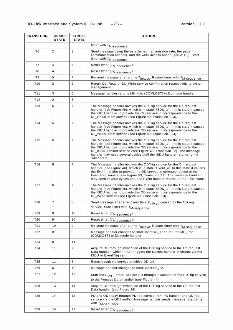
IO-Link Interface and System © IO-Link – 85 – Version 1.1.2
TRANSITION SOURCE STATE
TARGET STATE
ACTION
timer with TM-sequence.
T6 2 3 Send message using the established transmission rate, the page communication channel, and the write access option (see A.1.2). Start timer with TM-sequence.
T7 4 5 Reset timer (TM-sequence).
T8 4 5 Reset timer (TM-sequence).
T9 5 4 Re-send message after a time Tinitcyc. Restart timer with TM-sequence.
T10 3 2 Return DL_Read or DL_Write service confirmation respectively to system management.
T11 3 0 Message handler returns MH_Info (COMLOST) to DL-mode handler.
T12 2 6 -
T13 6 7 The Message handler invokes the ODTrig service for the On-request handler (see Figure 46), which is in state "ISDU_1". In this state it causes the ISDU handler to provide the OD service in correspondence to the DL_ReadParam service (see Figure 49, Transition T13).
T14 6 7 The Message handler invokes the ODTrig service for the On-request handler (see Figure 46), which is in state "ISDU_1". In this state it causes the ISDU handler to provide the OD service in correspondence to the DL_WriteParam service (see Figure 49, Transition T13).
T15 6 7 The Message handler invokes the ODTrig service for the On-request handler (see Figure 46), which is in state "ISDU_1". In this state it causes the ISDU handler to provide the OD service in correspondence to the DL_ISDUTransort service (see Figure 49, Transition T2). The message handler may need several cycles until the ISDU handler returns to the "idle" state.
T16 6 7 The Message handler invokes the ODTrig service for the On-request handler (see Figure 46), which is in state "Event_4". In this state it causes the Event handler to provide the OD service in correspondence to the EventFlag service (see Figure 53, Transition T2). The message handler may need several cycles until the Event handler returns to the "idle" state.
T17 6 7 The Message handler invokes the ODTrig service for the On-request handler (see Figure 46), which is in state "ISDU_1". In this state it causes the ISDU handler to provide the OD service in correspondence to the DL_Write service (see Figure 49, Transition T13).
T18 7 8 Send message after a recovery time Tinitcyc caused by the OD.req service. Start timer with TM-sequence.
T19 9 10 Reset timer (TM-sequence).
T20 9 10 Reset timer (TM-sequence).
T21 10 9 Re-send message after a time Tinitcyc. Restart timer with TM-sequence.
T22 8 0 Message handler changes to state Inactive_0 and returns MH_Info (COMLOST) to DL-mode handler.
T23 8 11 -
T24 11 7 Acquire OD through invocation of the ODTrig service to the On-request Data handler, which in turn triggers the current handler in charge via the ISDU or EventTrig call.
T25 11 6 Return result via service primitive OD.cnf
T26 6 12 Message handler changes to state Operate_12.
T27 12 13 Start the tCYC -timer. Acquire PD through invocation of the PDTrig service to the Process Data handler (see Figure 44).
T28 13 14 Acquire OD through invocation of the ODTrig service to the On-request Data handler (see Figure 46).
T29 14 15 PD and OD ready through PD.req service from PD handler and OD.req service via the OD handler. Message handler sends message. Start timer with TM-sequence.
T30 16 17 Reset timer (TM-sequence).

Version 1.1.2 – 86 – IO-Link Interface and System © IO-Link
TRANSITION SOURCE STATE
TARGET STATE
ACTION
T31 16 17 Reset timer (TM-sequence).
T32 17 16 Re-send message after a time tCYC. Restart timer with TM-sequence.
T33 15 0 Message handler changes to state Inactive_0 and returns MH_Info (COMLOST) to DL-mode handler.
T34 15 12 Device response message is correct. Return PD via service PD.cnf and via call PDTrig to the PD handler (see Table 46). Return OD via service OD.cnf and via call ODTrig to the On-request Data hander, which redirects it to the ISDU (see Table 51), Command (see Table 54), or Event handler (see Table 57) in charge.
T35 12 0 Message handler changes to state Inactive_0 and returns MH_Info (COMLOST) to the DL-mode handler.
T36 6 0 Message handler changes to state Inactive_0 and returns MH_Info (COMLOST) to the DL-mode handler.
T37 6 2 -
T38 12 2 -
T39 2 12 - 1630
INTERNAL ITEMS TYPE DEFINITION
Retry Variable Retry counter
MaxRetry Constant MaxRetry = 2, see Table 97
tM-sequence Time See equation (A.6)
tCYC Time The DL_SetMode service provides this value with its parameter "M-sequenceTime". See equation (A.7)
tinitcyc Time See A.2.6
MH_Conf_xxx Call See Table 42
1631
7.3.3.5 State machine of the Device message handler 1632
Figure 42 shows the state machine of the Device message handler. 1633
Idle_1
tm(MaxCycleTime)/T10tm(MaxCycleTime)/T10
PL_Transfer/T2
GetMessage_2
tm(MaxUARTframeTime)/T9
PL_Transfer/T3
PL_Transfer/T2
tm(MaxUARTframeTime)/T9
PL_Transfer/T3
CheckMessage_3
[ChecksumError]/T7
[Completed]/T4
[TypeError]/T8
[ChecksumError]/T7
[Completed]/T4
[TypeError]/T8
[Ready]/T6 (send)
CreateMessage_4
[Ready]/T6 (send)
[No error]/T5[No error]/T5
Inactive_0
/Initialization
MH_Conf_ACTIVE/T1
MH_Conf_INACTIVE/T11
MH_Conf_ACTIVE/T1
MH_Conf_INACTIVE/T11
1634
Figure 42 – State machine of the Device message handler 1635
Table 45 shows the state transition tables of the Device message handler. 1636
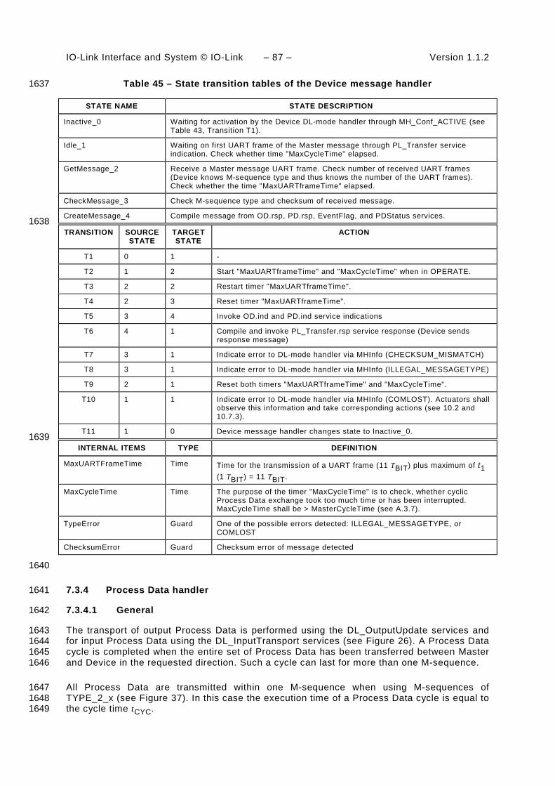
IO-Link Interface and System © IO-Link – 87 – Version 1.1.2
Table 45 – State transition tables of the Device message handler 1637
STATE NAME STATE DESCRIPTION
Inactive_0 Waiting for activation by the Device DL-mode handler through MH_Conf_ACTIVE (see Table 43, Transition T1).
Idle_1 Waiting on first UART frame of the Master message through PL_Transfer service indication. Check whether time "MaxCycleTime" elapsed.
GetMessage_2 Receive a Master message UART frame. Check number of received UART frames (Device knows M-sequence type and thus knows the number of the UART frames). Check whether the time "MaxUARTframeTime" elapsed.
CheckMessage_3 Check M-sequence type and checksum of received message.
CreateMessage_4 Compile message from OD.rsp, PD.rsp, EventFlag, and PDStatus services. 1638
TRANSITION SOURCE STATE
TARGET STATE
ACTION
T1 0 1 -
T2 1 2 Start "MaxUARTframeTime" and "MaxCycleTime" when in OPERATE.
T3 2 2 Restart timer "MaxUARTframeTime".
T4 2 3 Reset timer "MaxUARTframeTime".
T5 3 4 Invoke OD.ind and PD.ind service indications
T6 4 1 Compile and invoke PL_Transfer.rsp service response (Device sends response message)
T7 3 1 Indicate error to DL-mode handler via MHInfo (CHECKSUM_MISMATCH)
T8 3 1 Indicate error to DL-mode handler via MHInfo (ILLEGAL_MESSAGETYPE)
T9 2 1 Reset both timers "MaxUARTframeTime" and "MaxCycleTime".
T10 1 1 Indicate error to DL-mode handler via MHInfo (COMLOST). Actuators shall observe this information and take corresponding actions (see 10.2 and 10.7.3).
T11 1 0 Device message handler changes state to Inactive_0. 1639
INTERNAL ITEMS TYPE DEFINITION
MaxUARTFrameTime Time Time for the transmission of a UART frame (11 TBIT) plus maximum of t1 (1 TBIT) = 11 TBIT.
MaxCycleTime Time The purpose of the timer "MaxCycleTime" is to check, whether cyclic Process Data exchange took too much time or has been interrupted. MaxCycleTime shall be > MasterCycleTime (see A.3.7).
TypeError Guard One of the possible errors detected: ILLEGAL_MESSAGETYPE, or COMLOST
ChecksumError Guard Checksum error of message detected
1640
7.3.4 Process Data handler 1641
7.3.4.1 General 1642
The transport of output Process Data is performed using the DL_OutputUpdate services and 1643 for input Process Data using the DL_InputTransport services (see Figure 26). A Process Data 1644 cycle is completed when the entire set of Process Data has been transferred between Master 1645 and Device in the requested direction. Such a cycle can last for more than one M-sequence. 1646
All Process Data are transmitted within one M-sequence when using M-sequences of 1647 TYPE_2_x (see Figure 37). In this case the execution time of a Process Data cycle is equal to 1648 the cycle time tCYC. 1649
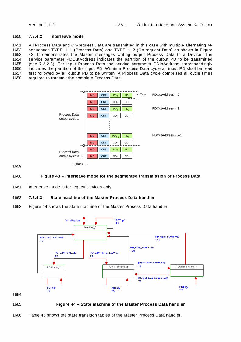
Version 1.1.2 – 88 – IO-Link Interface and System © IO-Link
7.3.4.2 Interleave mode 1650
All Process Data and On-request Data are transmitted in this case with multiple alternating M-1651 sequences TYPE_1_1 (Process Data) and TYPE_1_2 (On-request Data) as shown in Figure 1652 43. It demonstrates the Master messages writing output Process Data to a Device. The 1653 service parameter PDOutAddress indicates the partition of the output PD to be transmitted 1654 (see 7.2.2.3). For input Process Data the service parameter PDInAddress correspondingly 1655 indicates the partition of the input PD. Within a Process Data cycle all input PD shall be read 1656 first followed by all output PD to be written. A Process Data cycle comprises all cycle times 1657 required to transmit the complete Process Data. 1658
MC CKT PD0 PD1
MC CKT OD0 OD1
MC CKT PD2 PD3
MC CKT OD0 OD1
MC CKT PDx-1 PDx
MC CKT OD0 OD1
MC CKT PD0 PD1
MC CKT OD0 OD1
Process Dataoutput cycle n
Process Dataoutput cycle n+1
TCYC
t (time)
PDOutAddress = 0
PDOutAddress = 2
PDOutAddress = x-1
1659
Figure 43 – Interleave mode for the segmented transmission of Process Data 1660
Interleave mode is for legacy Devices only. 1661
7.3.4.3 State machine of the Master Process Data handler 1662
Figure 44 shows the state machine of the Master Process Data handler. 1663
/initialization
Inactive_0
PDTrig/T1PDTrig/T1
PD_Conf_SINGLE/T2
PDSingle_1
PDTrig/T3
PD_Conf_INACTIVE/T9
PD_Conf_SINGLE/T2
PDTrig/T3
PD_Conf_INACTIVE/T9
PD_Conf_INTERLEAVE/T4
PDInInterleave_2
PD_Conf_INTERLEAVE/T4
PD_Conf_INACTIVE/T10
PDTrig/T5
PD_Conf_INACTIVE/T10
PDTrig/T5
[Input Data Completed]/T6 PDOutInterleave_3
[Input Data Completed]/T6
[Output Data Completed]/T8
PDTrig/T7
PD_Conf_INACTIVE/T11
[Output Data Completed]/T8
PDTrig/T7
PD_Conf_INACTIVE/T11
1664
Figure 44 – State machine of the Master Process Data handler 1665
Table 46 shows the state transition tables of the Master Process Data handler. 1666

IO-Link Interface and System © IO-Link – 89 – Version 1.1.2
Table 46 – State transition tables of the Master Process Data handler 1667
STATE NAME STATE DESCRIPTION
Inactive_0 Waiting for activation
PDSingle_1 Process Data communication within one single M-sequence
PDInInterleave_2 Input Process Data communication in interleave mode
PDOutInterleave_3 Output Process Data communication in interleave mode 1668
TRANSITION SOURCE STATE
TARGET STATE
ACTION
T1 0 0 Invoke PD.req with no Process Data
T2 0 1 NOTE The DL-mode handler configured the Process Data handler for single PD transmission (see Table 42, T10 or T11).
T3 1 1 Take data from DL_PDOutputUpdate service and invoke PD.req to propagate output PD to the message handler. Take data from PD.cnf and invoke DL_PDInputTransport.ind and DL_PDCycle.ind to propagate input PD to the AL.
T4 0 2 NOTE Configured for interleave PD transmission (see Table 42, T10 or T11).
T5 2 2 Invoke PD.req and use PD.cnf to prepare DL_PDInputTransport.ind.
T6 2 3 Invoke DL_PDInputTransport.ind and DL_PDCycle.ind to propagate input PD to the AL (see 7.2.1.11).
T7 3 3 Take data from DL_PDOutputUpdate service and invoke PD.req to propagate output PD to the message handler.
T8 3 2 Invoke DL_PDCycle.ind to indicate end of Process Data cycle to the AL (see 7.2.1.12).
T9 1 0 -
T10 2 0 -
T11 3 0 - 1669
INTERNAL ITEMS TYPE DEFINITION
<None>
1670
7.3.4.4 State machine of the Device Process Data handler 1671
Figure 45 shows the state machine of the Device Process Data handler. 1672
Inactive_0
PD_ind/T1
/initializationPD_ind/T1
PD_Conf_ACTIVE/T2
PDActive_1
PD_Conf_INACTIVE/T8
DL_PDInputUpdate/T3
PD_Conf_ACTIVE/T2
PD_Conf_INACTIVE/T8
DL_PDInputUpdate/T3
PD_ind/T4 HandlePD_2
PD_ind/T4
[PD incomplete]/T5
[PD complete]/T6
[Cycle complete]/T7
[PD incomplete]/T5
[PD complete]/T6
[Cycle complete]/T7
1673
Figure 45 – State machine of the Device Process Data handler 1674

Version 1.1.2 – 90 – IO-Link Interface and System © IO-Link
See sequence diagrams in Figure 65 and Figure 66 for context. 1675
Table 47 shows the state transition tables of the Device Process Data handler 1676
Table 47 – State transition tables of the Device Process Data handler 1677
STATE NAME STATE DESCRIPTION
Inactive_0 Waiting on activation
PDActive_1 Handler active and waiting on next message handler demand via PD service or DL_PDInputUpdate service from AL.
HandlePD_2 Check Process Data for completeness in interleave mode 1678
TRANSITION SOURCE STATE
TARGET STATE
ACTION
T1 0 0 Ignore Process Data
T2 0 1 -
T3 1 1 Prepare input Process Data for PD.rsp for next message handler demand
T4 1 2 Message handler demands input PD via a PD.ind service and delivers output PD or segment of output PD. Invoke PD.rsp with input Process Data when in non-interleave mode (see 7.2.2.3).
T5 2 1 -
T6 2 1 Invoke DL_PDOutputTransport.ind (see 7.2.1.9)
T7 2 1 Invoke DL_PDCycle.ind (see 7.2.1.12)
T8 1 0 - 1679
INTERNAL ITEMS TYPE DEFINITION
PD_ind Label Invocation of service PD.ind occurred from message handler
1680
7.3.5 On-request Data handler 1681
7.3.5.1 General 1682
The Master On-request Data handler is a subordinate state machine active in the "Startup_2", 1683 "PreOperate_3", and "Operate_4" state of the DL-mode handler (see Figure 33). It controls 1684 three other state machines, the so-called ISDU handler, the command handler, and the Event 1685 handler. It always starts with the ISDU handler by default. 1686
Whenever an EventFlag.ind is received, the state machine will change to the Event handler. 1687 After the complete readout of the Event information it will return to the ISDU handler state. 1688
Whenever a DL_Control.req or PDInStatus.ind service is received while in the ISDU handler 1689 or in the Event handler, the state machine will change to the command handler. Once the 1690 command has been served, the state machine will return to the previously active state (ISDU 1691 or Event). 1692
7.3.5.2 State machine of the Master On-request Data handler 1693
Figure 46 shows the Master state machine of the On-request Data handler. 1694
The On-request Data handler redirects the ODTrig.ind service primitive for the next message 1695 content to the currently active subsidiary handler (ISDU, command, or Event). This is 1696 performed through one of the ISDUTrig, CommandTrig, or EventTrig calls. 1697

IO-Link Interface and System © IO-Link – 91 – Version 1.1.2
ODTrig/T2
ISDU_1
ODTrig/T2
DL_Control/T3
Command_2
[Done & Not EventActive]/T4
ODTrig/T9
DL_Control/T3
[Done & Not EventActive]/T4
ODTrig/T9
EventFlag/T5
Event_3
EventFlag/T5
[Done]/T6
DL_Control/T7
[Done & EventActive]/T8
ODTrig/T10
[Done]/T6
DL_Control/T7
[Done & EventActive]/T8
ODTrig/T10
Inactive_0
OH_Conf_ACTIVE/T1
OH_Conf_INACTIVE/T13
OH_Conf_INACTIVE/T12
OH_Conf_INACTIVE/T11
/initialization
OH_Conf_ACTIVE/T1
OH_Conf_INACTIVE/T13
OH_Conf_INACTIVE/T12
OH_Conf_INACTIVE/T11
1698
Figure 46 – State machine of the Master On-request Data handler 1699
Table 48 shows the state transition tables of the Master On-request Data handler. 1700
Table 48 – State transition tables of the Master On-request Data handler 1701
STATE NAME STATE DESCRIPTION
Inactive_0 Waiting on activation
ISDU_1 Default state of the on-request handler (lowest priority)
Command_2 State to control the Device via commands with highest priority
Event_3 State to convey Event information (errors, warnings, notifications) with higher priority 1702
TRANSITION SOURCE STATE
TARGET STATE
ACTION
T1 0 1 -
T2 1 1 On-request Data handler propagates the ODTrig.ind service now named ISDUTrig to the ISDU handler (see Figure 49). In case of DL_Read, DL_Write, DL_ReadParam, or DL_WriteParam services, the ISDU handler will use a separate transition (see Figure 49, T13).
T3 1 2 -
T4 2 1 -
T5 1 3 EventActive = TRUE
T6 3 1 EventActive = FALSE
T7 3 2 -
T8 2 3 -
T9 2 2 On-request Data handler propagates the ODTrig.ind service now named CommandTrig to the command handler (see Figure 51)
T10 3 3 On-request Data handler propagates the ODTrig.ind service now named EventTrig to the Event handler (see Figure 53)
T11 2 0 -
T12 3 0 -
T13 1 0 - 1703
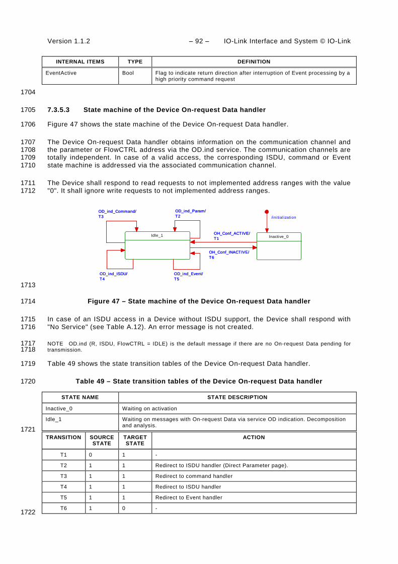
Version 1.1.2 – 92 – IO-Link Interface and System © IO-Link
INTERNAL ITEMS TYPE DEFINITION
EventActive Bool Flag to indicate return direction after interruption of Event processing by a high priority command request
1704
7.3.5.3 State machine of the Device On-request Data handler 1705
Figure 47 shows the state machine of the Device On-request Data handler. 1706
The Device On-request Data handler obtains information on the communication channel and 1707 the parameter or FlowCTRL address via the OD.ind service. The communication channels are 1708 totally independent. In case of a valid access, the corresponding ISDU, command or Event 1709 state machine is addressed via the associated communication channel. 1710
The Device shall respond to read requests to not implemented address ranges with the value 1711 "0". It shall ignore write requests to not implemented address ranges. 1712
Idle_1
OD_ind_Command/T3
OD_ind_Param/T2
OD_ind_ISDU/T4
OD_ind_Event/T5
OD_ind_Command/T3
OD_ind_Param/T2
OD_ind_ISDU/T4
OD_ind_Event/T5
/initialization
Inactive_0OH_Conf_ACTIVE/T1
OH_Conf_INACTIVE/T6
OH_Conf_ACTIVE/T1
OH_Conf_INACTIVE/T6
1713
Figure 47 – State machine of the Device On-request Data handler 1714
In case of an ISDU access in a Device without ISDU support, the Device shall respond with 1715 "No Service" (see Table A.12). An error message is not created. 1716
NOTE OD.ind (R, ISDU, FlowCTRL = IDLE) is the default message if there are no On-request Data pending for 1717 transmission. 1718
Table 49 shows the state transition tables of the Device On-request Data handler. 1719
Table 49 – State transition tables of the Device On-request Data handler 1720
STATE NAME STATE DESCRIPTION
Inactive_0 Waiting on activation
Idle_1 Waiting on messages with On-request Data via service OD indication. Decomposition and analysis.
1721 TRANSITION SOURCE
STATE TARGET STATE
ACTION
T1 0 1 -
T2 1 1 Redirect to ISDU handler (Direct Parameter page).
T3 1 1 Redirect to command handler
T4 1 1 Redirect to ISDU handler
T5 1 1 Redirect to Event handler
T6 1 0 - 1722

IO-Link Interface and System © IO-Link – 93 – Version 1.1.2
INTERNAL ITEMS TYPE DEFINITION
OD_ind_Param Service Alias for Service OD.ind (R/W, PAGE, 16 to 31, Data) in case of DL_ReadParam or DL_WriteParam
OD_ind_Command Service Alias for Service OD.ind (W, PAGE, 0, MasterCommand)
OD_ind_ISDU Service Alias for Service OD.ind (R/W, ISDU, FlowCtrl, Data)
OD_ind_Event Service Alias for Service OD.ind (R/W, DIAGNOSIS, n, Data)
1723
7.3.6 ISDU handler 1724
7.3.6.1 Indexed Service Data Unit (ISDU) 1725
The general structure of an ISDU is demonstrated in Figure 48 and specified in detail in 1726 Clause A.5. 1727
I-Service
ExtLength
Index
Subindex
Data 1
...
Length
Data n
CHKPDU = Checksum
I-Service
ExtLength
Index
Subindex
Data 1
...
Length
Data n
CHKPDU = Checksum 1728
Figure 48 – Structure of the ISDU 1729
The sequence of the elements corresponds to the transmission sequence. The elements of an 1730 ISDU can take various forms depending on the type of I-Service (see A.5.2 and Table A.12). 1731
The ISDU allows accessing data objects (parameters and commands) to be transmitted (see 1732 Figure 5). The data objects shall be addressed by the “Index” element. 1733
All multi-octet data types shall be transmitted as a big-endian sequence, i.e. the most 1734 significant octet (MSO) shall be sent first, followed by less significant octets in descending 1735 order, with the least significant octet (LSO) being sent last, as shown in Figure 2. 1736
7.3.6.2 Transmission of ISDUs 1737
An ISDU is transmitted via the ISDU communication channel (see Figure 7 and A.1.2). A 1738 number of messages are typically required to perform this transmission (segmentation). The 1739 Master transfers an ISDU by sending an I-Service (Read/Write) request to the Device via the 1740 ISDU communication channel. It then receives the Device’s response via the same channel. 1741
In the ISDU communication channel, the "Address" element within the M-sequence control 1742 octet accommodates a counter (= FlowCTRL). FlowCTRL is controlling the segmented data 1743 flow (see A.1.2) by counting the M-sequences necessary to transmit an ISDU. 1744
The Master uses the "Length" element of the ISDU and FlowCTRL to check the 1745 accomplishment of the complete transmission. 1746

Version 1.1.2 – 94 – IO-Link Interface and System © IO-Link
Permissible values for FlowCTRL are specified in Table 50. 1747
Table 50 – FlowCTRL definitions 1748
FlowCTRL Definition
0x00 to 0x0F COUNT M-sequence counter within an ISDU. Increments beginning with 1 after an ISDU START. Jumps back from 15 to 0 in the Event of an overflow.
0x10 START Start of an ISDU I-Service, i.e., start of a request or a response. For the start of a request, any previously incomplete services may be rejected. For a start request associated with a response, a Device shall send “No Service” until its application returns response data (see Table A.12).
0x11 IDLE 1 No request for ISDU transmission.
0x12 IDLE 2: Reserved for future use No request for ISDU transmission.
0x13 to 0x1E Reserved
0x1F ABORT Abort entire service. The Master responds by rejecting received response data. The Device responds by rejecting received request data and may generate an abort.
1749 In state Idle_1, values 0x12 to 0x1F shall not lead to a communication error. 1750
7.3.6.3 State machine of the Master ISDU handler 1751
Figure 49 shows the state machine of the Master ISDU handler. 1752
Inactive_0
/Initialization
Idle_1
ISDUTrig[ ParamRequest]/T13
ISDUTrig/T14
IH_Conf_ACTIVE/T1
IH_Conf_INACTIVE/T16
ISDUTrig[ ParamRequest]/T13
ISDUTrig/T14
IH_Conf_ACTIVE/T1
IH_Conf_INACTIVE/T16
ISDUTrig[ DL_ISDUTransport]/T2 ISDURequest_2
ISDUTrig[ DL_ISDUTransport]/T2
ISDUTrig/T3ISDUTrig/T3
ISDUWait_3
ISDUTrig/T5
[Data written]/T4
ISDUTrig/T5
[Data written]/T4
DL_Mode_COMLOST/T12
ISDUError_4
DL_Mode_COMLOST/T12
[Error]/T9
ISDUTrig/T11IH_Conf_INACTIVE/
T15
DL_ISDUAbort/T17
DL_ISDUAbort/T19
[Error]/T9
ISDUTrig/T11IH_Conf_INACTIVE/
T15
DL_ISDUAbort/T17
DL_ISDUAbort/T19
ISDUResponse_5
[ResponseStart]/T6[Error]/
T10
ISDUTrig[ Transmission completed]/T8
ISDUTrig/T7
DL_ISDUAbort/T18
[ResponseStart]/T6[Error]/
T10
ISDUTrig[ Transmission completed]/T8
ISDUTrig/T7
DL_ISDUAbort/T18
1753
Figure 49 – State machine of the Master ISDU handler 1754
Table 51 shows the state transition tables of the Master ISDU handler. 1755

IO-Link Interface and System © IO-Link – 95 – Version 1.1.2
Table 51 – State transition tables of the Master ISDU handler 1756
STATE NAME STATE DESCRIPTION
Inactive_0 Waiting on activation
Idle_1 Waiting on transmission of next On-request Data
ISDURequest_2 Transmission of ISDU request data
ISDUWait_3 Waiting on response from Device. Observe ISDUTime
ISDUError_4 Error handling after detected errors: Invoke negative DL_ISDU_Transport response with ISDUTransportErrorInfo
ISDUResponse_5 Get response data from Device 1757
TRANSITION SOURCE STATE
TARGET STATE
ACTION
T1 0 1 -
T2 1 2 Invoke OD.req with ISDU write start condition: OD.req (W, ISDU, flowCtrl = START, data)
T3 2 2 Invoke OD.req with ISDU data write and FlowCTRL under conditions of Table 50
T4 2 3 Start timer (ISDUTime)
T5 3 3 Invoke OD.req with ISDU read start condition: OD.req (R, ISDU, flowCtrl = START)
T6 3 5 Stop timer (ISDUTime)
T7 5 5 Invoke OD.req with ISDU data read and FlowCTRL under conditions of Table 50
T8 5 1 Invoke positive DL_ ISDUTransport confirmation
T9 3 4 -
T10 5 4 -
T11 4 1 Invoke OD.req with ISDU abortion: OD.req (R, ISDU, flowCtrl = ABORT). Invoke negative DL_ ISDUTransport confirmation
T12 2 4 -
T13 1 1 Invoke OD.req with appropriate data. Invoke positive DL_ReadParam/DL_WriteParam confirmation
T14 1 1 Invoke OD.req with idle message: OD.req (R, ISDU, flowCtrl = IDLE)
T15 4 1 In case of lost communication the message handler informs the DL_Mode handler which in turn uses the administrative call IH_Conf_INACTIVE. No actions during this transition required.
T16 1 0 -
T17 3 4 -
T18 5 4 -
T19 2 4 - 1758
INTERNAL ITEMS TYPE DEFINITION
ISDUTime Time Measurement of Device response time (watchdog, see Table 97)
ResponseStart Service OD.cnf (data different from ISDU_BUSY)
ParamRequest Service DL_ReadParam or DL_WriteParam
Error Variable Any detectable error within the ISDU transmission or DL_ISDUAbort requests, or any violation of the ISDU acknowledgement time (see Table 97)
1759
7.3.6.4 State machine of the Device ISDU handler 1760
Figure 50 shows the state machine of the Device ISDU handler. 1761

Version 1.1.2 – 96 – IO-Link Interface and System © IO-Link
Idle_1
ISDURead/T14ISDURead/T14
ISDURequest_2
ISDUStart/T2
ISDUAbort/T9
ISDUWrite/T3
[ISDUError]/T13
ISDUStart/T2
ISDUAbort/T9
ISDUWrite/T3
[ISDUError]/T13
ISDUResponse_4
ISDURead/T7
ISDUAbort/T11
[ISDUSendComplete]/T8
ISDURead/T7
ISDUAbort/T11
[ISDUSendComplete]/T8
ISDUWait_3
[ISDURecComplete]/T4ISDUAbort/
T10
ISDURespStart/T6
ISDURead/T5
[ISDURecComplete]/T4ISDUAbort/
T10
ISDURespStart/T6
ISDURead/T5
Inactive_0
IH_Conf_ACTIVE/T1
IH_Conf_INACTIVE/T12
/Initialization
IH_Conf_ACTIVE/T1
IH_Conf_INACTIVE/T12
1762
Figure 50 – State machine of the Device ISDU handler 1763
Table 52 shows the state transition tables of the Device ISDU handler. 1764
Table 52 – State transition tables of the Device ISDU handler 1765
STATE NAME STATE DESCRIPTION
Inactive_0 Waiting on activation
Idle_1 Waiting on next ISDU transmission
ISDURequest_2 Reception of ISDU request
ISDUWait_3 Waiting on data from application layer to transmit (see DL_ISDUTransport)
ISDUResponse_4 Transmission of ISDU response data 1766
TRANSITION SOURCE STATE
TARGET STATE
ACTION
T1 0 1 -
T2 1 2 Start receiving of ISDU request data
T3 2 2 Receive ISDU request data
T4 2 3 Invoke DL_ ISDUTransport.ind to AL (see 7.2.1.6)
T5 3 3 Invoke OD.rsp with "busy" indication (see Table A.14)
T6 3 4 -
T7 4 4 Invoke OD.rsp with ISDU response data
T8 4 1 -
T9 2 1 -
T10 3 1 Invoke DL_ ISDUAbort
T11 4 1 Invoke DL_ ISDUAbort
T12 1 0 -
T13 2 1 -
T14 1 1 Invoke OD.rsp with "no service" indication (see Table A.12 and Table A.14)
1767 INTERNAL ITEMS TYPE DEFINITION
ISDUStart Service OD.ind(W, ISDU, Start, Data)
ISDUWrite Service OD.ind(W, ISDU, FlowCtrl, Data)
ISDURecComplete Guard If OD.ind(R, ISDU, Start, ...) received

IO-Link Interface and System © IO-Link – 97 – Version 1.1.2
INTERNAL ITEMS TYPE DEFINITION
ISDURespStart Service DL_ ISDUTransport.rsp()
ISDURead Service OD.ind(R, ISDU, Start or FlowCtrl, ...)
ISDUSendComplete Guard If OD.ind(R, ISDU, IDLE, ...) received
ISDUAbort Service OD.ind(R/W, ISDU, Abort, ...)
ISDUError Guard If ISDU structure is incorrect
1768
7.3.7 Command handler 1769
7.3.7.1 General 1770
The command handler passes the control code (PDOUTVALID or PDOUTINVALID) contained 1771 in the DL_Control.req service primitive to the cyclically operating message handler via the 1772 OD.req service and MasterCommands. The message handler uses the page communication 1773 channel. 1774
The permissible control codes for output Process Data are listed in Table 53. 1775
Table 53 – Control codes 1776
Control code MasterCommand Description
PDOUTVALID ProcessDataOutputOperate Output Process Data valid
PDOUTINVALID DeviceOperate Output Process Data invalid or missing
1777 The command handler receives input Process Data status information via the PDInStatus 1778 service and propagates it within a DL_Control.ind service primitive. 1779
In addition, the command handler translates Device mode change requests from system 1780 management into corresponding MasterCommands (see Table B.2). 1781
7.3.7.2 State machine of the Master command handler 1782
Figure 51 shows the state machine of the Master command handler. 1783
Inactive_0
/Initialization
Idle_1
PDInStatus/T2
CH_Conf_ACTIVE/T1
CH_Conf_INACTIVE/T6
PDInStatus/T2
CH_Conf_ACTIVE/T1
CH_Conf_INACTIVE/T6
MasterCommand_2DL_Write_DEVICEMODE/T4
CommandTrig/T5
DL_Control_PDOUT/T3
DL_Write_DEVICEMODE/T4
CommandTrig/T5
DL_Control_PDOUT/T3
1784
Figure 51 – State machine of the Master command handler 1785
Table 54 shows the state transition tables of the Master command handler. 1786
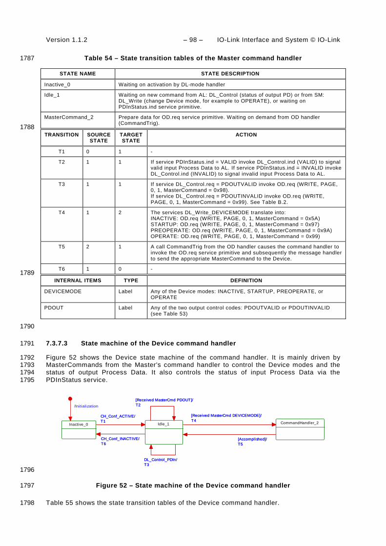
Version 1.1.2 – 98 – IO-Link Interface and System © IO-Link
Table 54 – State transition tables of the Master command handler 1787
STATE NAME STATE DESCRIPTION
Inactive_0 Waiting on activation by DL-mode handler
Idle_1 Waiting on new command from AL: DL_Control (status of output PD) or from SM: DL_Write (change Device mode, for example to OPERATE), or waiting on PDInStatus.ind service primitive.
MasterCommand_2 Prepare data for OD.req service primitive. Waiting on demand from OD handler (CommandTrig).
1788 TRANSITION SOURCE
STATE TARGET STATE
ACTION
T1 0 1 -
T2 1 1 If service PDInStatus.ind = VALID invoke DL_Control.ind (VALID) to signal valid input Process Data to AL. If service PDInStatus.ind = INVALID invoke DL_Control.ind (INVALID) to signal invalid input Process Data to AL.
T3 1 1 If service DL_Control.req = PDOUTVALID invoke OD.req (WRITE, PAGE, 0, 1, MasterCommand = 0x98). If service DL_Control.req = PDOUTINVALID invoke OD.req (WRITE, PAGE, 0, 1, MasterCommand = 0x99). See Table B.2.
T4 1 2 The services DL_Write_DEVICEMODE translate into: INACTIVE: OD.req (WRITE, PAGE, 0, 1, MasterCommand = 0x5A) STARTUP: OD.req (WRITE, PAGE, 0, 1, MasterCommand = 0x97) PREOPERATE: OD.req (WRITE, PAGE, 0, 1, MasterCommand = 0x9A) OPERATE: OD.req (WRITE, PAGE, 0, 1, MasterCommand = 0x99)
T5 2 1 A call CommandTrig from the OD handler causes the command handler to invoke the OD.req service primitive and subsequently the message handler to send the appropriate MasterCommand to the Device.
T6 1 0 - 1789
INTERNAL ITEMS TYPE DEFINITION
DEVICEMODE Label Any of the Device modes: INACTIVE, STARTUP, PREOPERATE, or OPERATE
PDOUT Label Any of the two output control codes: PDOUTVALID or PDOUTINVALID (see Table 53)
1790
7.3.7.3 State machine of the Device command handler 1791
Figure 52 shows the Device state machine of the command handler. It is mainly driven by 1792 MasterCommands from the Master's command handler to control the Device modes and the 1793 status of output Process Data. It also controls the status of input Process Data via the 1794 PDInStatus service. 1795
Idle_1
[Received MasterCmd PDOUT]/T2
DL_Control_PDIn/T3
[Received MasterCmd PDOUT]/T2
DL_Control_PDIn/T3
[Accomplished]/T5
CommandHandler_2
[Accomplished]/T5
[Received MasterCmd DEVICEMODE]/T4[Received MasterCmd DEVICEMODE]/T4
Inactive_0
CH_Conf_ACTIVE/T1
CH_Conf_INACTIVE/T6
/Initialization
CH_Conf_ACTIVE/T1
CH_Conf_INACTIVE/T6
1796
Figure 52 – State machine of the Device command handler 1797
Table 55 shows the state transition tables of the Device command handler. 1798

IO-Link Interface and System © IO-Link – 99 – Version 1.1.2
Table 55 – State transition tables of the Device command handler 1799
STATE NAME STATE DESCRIPTION
Inactive_0 Waiting on activation
Idle_1 Waiting on next MasterCommand
CommandHandler_2 Decompose MasterCommand and invoke specific actions (see B.1.2): If MasterCommand = 0x5A then change Device state to INACTIVE. If MasterCommand = 0x97 then change Device state to STARTUP. If MasterCommand = 0x9A then change Device state to PREOPERATE. If MasterCommand = 0x99 then change Device state to OPERATE.
1800 TRANSITION SOURCE
STATE TARGET STATE
ACTION
T1 0 1 -
T2 1 1 Invoke DL_Control.ind (PDOUTVALID) if received MasterCommand = 0x98. Invoke DL_Control.ind (PDOUTINVALID) if received MasterCommand = 0x99.
T3 1 1 If service DL_Control.req (VALID) then invoke PDInStatus.req (VALID). If service DL_Control.req (INVALID) then invoke PDInStatus.req (INVALID). Message handler uses PDInStatus service to set/reset the PD status flag (see A.1.5)
T4 1 2 -
T5 2 1 -
T6 1 0 - 1801
INTERNAL ITEMS TYPE DEFINITION
<none>
1802
7.3.8 Event handler 1803
7.3.8.1 Events 1804
There are two types of Events, one without details, and another one with details. Events 1805 without details may have been implemented in legacy Devices, but they shall not be used for 1806 Devices in accordance with this standard. However, all Masters shall support processing of 1807 both Events with details and Events without details. 1808
The general structure and coding of Events is specified in A.6. Event codes without details 1809 are specified in Table A.16. EventCodes with details are specified in Annex D. The structure 1810 of the Event memory for EventCodes with details within a Device is specified in Table 56. 1811
Table 56 – Event memory 1812
Address Event slot number
Parameter Name Description
0x00 StatusCode Summary of status and error information. Also used to control read access for individual messages.
0x01 1 EventQualifier 1 Type, mode and source of the Event
0x02 EventCode 1 16-bit EventCode of the Event
0x03
0x04 2 EventQualifier 2 Type, mode and source of the Event
0x05 EventCode 2 16-bit EventCode of the Event
0x06
…
0x10 6 EventQualifier 6 Type, mode and source of the Event

Version 1.1.2 – 100 – IO-Link Interface and System © IO-Link
Address Event slot number
Parameter Name Description
0x11 EventCode 6 16-bit EventCode of the Event
0x12
0x13 to 0x1F Reserved for future use
1813
7.3.8.2 Event processing 1814
The Device AL writes an Event to the Event memory and then sets the "Event flag" bit, which 1815 is sent to the Master in the next message within the CKS octet (see 7.3.3.2 and A.1.5). 1816
Upon reception of a Device reply message with the "Event flag" bit = 1, the Master shall 1817 switch from the ISDU handler to the Event handler. The Event handler starts reading the 1818 StatusCode. 1819
If the "Event Details" bit is set (see Figure A.23), the Master shall read the Event details of 1820 the Events indicated in the StatusCode from the Event memory. Once it has read an Event 1821 detail, it shall invoke the service DL_Event.ind. After reception of the service DL_EventConf, 1822 the Master shall write any data to the StatusCode to reset the "Event flag" bit. The Event 1823 handling on the Master shall be completed regardless of the contents of the Event data 1824 received (EventQualifier, EventCode). 1825
If the "Event Details" bit is not set (see Figure A.22) the Master Event handler shall generate 1826 the standardized Events according to Table A.16 beginning with the most significant bit in the 1827 EventCode. 1828
Write access to the StatusCode indicates the end of Event processing to the Device. The 1829 Device shall ignore the data of this Master Write access. The Device then resets the "Event 1830 flag" bit and may now change the content of the fields in the Event memory. 1831
7.3.8.3 State machine of the Master Event handler 1832
Figure 53 shows the Master state machine of the Event handler. 1833
Inactive_0
/Initialization
Idle_1
EH_Conf_ACTIVE/T1
EH_Conf_INACTIVE/T10
EH_Conf_ACTIVE/T1
EH_Conf_INACTIVE/T10
EventTrig/T2
ReadEvent_2EventTrig/T2
DL_Mode_COMLOST/T6
EventTrig/T3
DL_Mode_COMLOST/T6
EventTrig/T3
[Events completed]/T4
SignalEvent_3
[Events completed]/T4
[Events reported]/T5[Events reported]/T5
DL_EventConf/T7EventConfirmation_4
EventTrig/T8
DL_Mode_COMLOST/T9
DL_EventConf/T7
EventTrig/T8
DL_Mode_COMLOST/T9
1834
Figure 53 – State machine of the Master Event handler 1835
Table 57 shows the state transition tables of the Master Event handler. 1836

IO-Link Interface and System © IO-Link – 101 – Version 1.1.2
Table 57 – State transition tables of the Master Event handler 1837
STATE NAME STATE DESCRIPTION
Inactive_0 Waiting on activation
Idle_1 Waiting on next Event indication ("EventTrig" through On-request Data handler) or Event confirmation through service DL_EventConf from Master AL.
ReadEvent_2 Read Event data set from Device message by message through Event memory address. Check StatusCode for number of activated Events (see Table 56).
SignalEvent_3 Analyze Event data and invoke DL_Event indication to Master AL (see 7.2.1.15) for each available Event.
EventConfirmation_4 Waiting on Event confirmation transmission via service OD.req to the Device 1838
TRANSITION SOURCE STATE
TARGET STATE
ACTION
T1 0 1 -
T2 1 2 Read Event StatusCode octet via service OD.req (R, DIAGNOSIS, Event memory address = 0, 1)
T3 2 2 Read octets from Event memory via service OD.req (R, DIAGNOSIS, incremented Event memory address, 1)
T4 2 3 -
T5 3 1 -
T6 2 0 -
T7 1 4 -
T8 4 1 Invoke OD.req (W, DIAGNOSIS, 0, 1, any data) with Write access to "StatusCode" (see Table 56) to confirm Event readout to Device
T9 4 0 -
T10 1 0 - 1839
INTERNAL ITEMS TYPE DEFINITION
<None>
1840
7.3.8.4 State machine of the Device Event handler 1841
Figure 54 shows the state machine of the Device Event handler. 1842
Idle_1
DL_Event /T2
EventRead/T6
DL_Event /T2
EventRead/T6
FreezeEventMemory_2DL_EventTrigger/T3
EventConf /T5
EventRead/T4
DL_EventTrigger/T3
EventConf /T5
EventRead/T4
Inactive_0
/InitializationEH_Conf_ACTIVE/T1
EH_Conf_INACTIVE/T7
EH_Conf ig_INACTIVE/T8
EH_Conf_ACTIVE/T1
EH_Conf_INACTIVE/T7
EH_Conf ig_INACTIVE/T8
1843
Figure 54 – State machine of the Device Event handler 1844
Table 58 shows the state transition tables of the Device Event handler. 1845

Version 1.1.2 – 102 – IO-Link Interface and System © IO-Link
Table 58 – State transition tables of the Device Event handler 1846
STATE NAME STATE DESCRIPTION
Inactive_0 Waiting on activation
Idle_1 Waiting on DL-Event service from AL providing Event data and the DL_EventTrigger service to fire the "Event flag" bit (see A.1.5)
FreezeEventMemory_2 Waiting on readout of the Event memory and on Event memory readout confirmation through write access to the StatusCode
1847 TRANSITION SOURCE
STATE TARGET STATE
ACTION
T1 0 1 -
T2 1 1 Change Event memory entries with new Event data (see Table 56)
T3 1 2 Invoke service EventFlag.req (Flag = TRUE) to indicate Event activation to the Master via the "Event flag" bit. Mark all Event slots in memory as not changeable.
T4 2 2 Master requests Event memory data via EventRead (= OD.ind). Send Event data by invoking OD.rsp with Event data of the requested Event memory address.
T5 2 1 Invoke service EventFlag.req (Flag = FALSE) to indicate Event deactivation to the Master via the "Event flag" bit. Mark all Event slots in memory as invalid according to A.6.3.
T6 1 1 Send contents of Event memory by invoking OD.rsp with Event data
T7 1 0 -
T8 2 0 Discard Event memory data 1848
INTERNAL ITEMS TYPE DEFINITION
EventRead Service OD.ind (R, DIAGNOSIS, Event memory address, length, data)
EventConf Service OD.ind (W, DIAGNOSIS, address = 0, data = don't care)
1849
8 Application layer (AL) 1850
8.1 General 1851
Figure 55 shows an overview of the structure and services of the Master application layer 1852 (AL). 1853

IO-Link Interface and System © IO-Link – 103 – Version 1.1.2
Systemmanagement
DL_
Eve
nt
DL_
PD
Out
-pu
tUpd
ate
DL_
PD
Inpu
t -Tr
ansp
ort
DL_
Rea
d-P
aram
DL_
Writ
e-P
aram
DL_
ISD
U-
Tran
spor
t
DL_
Con
trol
DL_
PD
Cyc
le
SM
_Set
Por
tCon
fig
SM
_Por
tMod
e
SM
_Get
Por
tCon
fig
SM
_Ope
rate
Application Layer
Data Link Layer
SIODI / DO
DL_SetMode
DL_Read
DL_Write
Process Dataobjects
On-request Dataobjects AL
AL_
Rea
d
AL_
Writ
e
AL_
Abo
rt
AL_
Con
trol
AL_
Eve
nt
AL_
Get
Inpu
t
AL_
New
Inpu
t
AL_
Set
Out
put
AL_
PD
Cyc
le
Port xHandler
Coordination On-request data handler Process data handler
Master applications
Gateway application (configuration, parameterization, diagnosis, on-request, and process data)
AL_Read
DL_
ISD
U-
Abo
rt
DL_
Eve
nt-
Con
f
Data Storage Process Data ExchangeConfiguration Manager Diagnosis UnitOn-request Data Exchange
1854
Figure 55 – Structure and services of the application layer (Master) 1855
1856
Figure 56 shows an overview of the structure and services of the Device application layer 1857 (AL). 1858
DL_
Eve
nt
DL_
PD
Inpu
t-U
pdat
e
DL_
PD
Out
put -
Tran
spor
t
DL_
Rea
d-P
aram
DL_
Writ
e -P
aram
DL_
ISD
U-
Tran
spor
t
DL_
Con
trol
DL_
PD
Cyc
le
DL_
Eve
nt-
Trig
ger
Systemmanage-ment
SM
_Set
Dev
iceI
dent
SM
_Get
Dev
iceC
omm
SM
_Dev
iceM
ode
SM
_Set
Dev
iceC
omm
SM
_Get
Dev
iceI
dent
SM
_Set
Dev
iceM
ode
Linehandler
Application LayerProcess Data
objectsOn-request Data
objects AL
AL_
Rea
d
AL_
Writ
e
AL_
Abo
rt
AL_
Con
trol
AL_
Eve
nt
AL_
Set
Inpu
t
AL_
Get
Out
put
AL_
New
Out
put
AL_
PD
Cyc
le
SIODI / DOOn-request data handler Process data handler
Data Link Layer
Data Storage (DS)
Device applications
Process Data Exchange (PDE)
Technology specific application (technology parameter, diagnosis, process data)
Parameter Manager (PM) Event Dispatcher (ED)
DL_
ISD
U-
Abo
rt
1859
Figure 56 – Structure and services of the application layer (Device) 1860
8.2 Application layer services 1861
8.2.1 AL services within Master and Device 1862
This clause defines the services of the application layer (AL) to be provided to the Master and 1863 Device applications and system management via its external interfaces. Table 59 lists the 1864

Version 1.1.2 – 104 – IO-Link Interface and System © IO-Link
assignments of Master and Device to their roles as initiator or receiver for the individual AL 1865 services. Empty fields indicate no availability of this service on Master or Device. 1866
Table 59 – AL services within Master and Device 1867
Service name Master Device
AL_Read R I
AL_Write R I
AL_Abort R I
AL_GetInput R
AL_NewInput I
AL_SetInput R
AL_PDCycle I I
AL_GetOutput R
AL_NewOutput I
AL_SetOutput R
AL_Event I / R R
AL_Control I / R I / R
Key (see 3.3.4) I Initiator of service R Receiver (Responder) of service
1868
8.2.2 AL Services 1869
8.2.2.1 AL_Read 1870
The AL_Read service is used to read On-request Data from a Device connected to a specific 1871 port. The parameters of the service primitives are listed in Table 60. 1872
Table 60 – AL_Read 1873
Parameter name .req .ind .rsp .cnf
Argument M M
Port M
Index M M
Subindex M M
Result (+) S S(=)
Port M
Data M M(=)
Result (-) S S(=)
Port M
ErrorInfo M M(=)
1874 Argument 1875 The service-specific parameters are transmitted in the argument. 1876
Port 1877 This parameter contains the port number for the On-request Data to be read. 1878

IO-Link Interface and System © IO-Link – 105 – Version 1.1.2
Parameter type: Unsigned8 1879
Index 1880 This parameter indicates the address of On-request Data objects to be read from the 1881 Device. Index 0 in conjunction with Subindex 0 addresses the entire set of Direct 1882 Parameters from 0 to 15 (see Direct Parameter page 1 in Table B.1) or in conjunction with 1883 Subindices 1 to 16 the individual parameters from 0 to 15. Index 1 in conjunction with 1884 Subindex 0 addresses the entire set of Direct Parameters from addresses 16 to 31 (see 1885 Direct Parameter page 2 in Table B.1) or in conjunction with Subindices 1 to 16 the 1886 individual parameters from 16 to 31. It uses the page communication channel (see Figure 1887 6) for both and always returns a positive result. For all the other indices (see B.2) the ISDU 1888 communication channel is used. 1889
Permitted values: 0 to 65535 (See B.2.1 for constraints) 1890
Subindex 1891 This parameter indicates the element number within a structured On-request Data object. A 1892 value of 0 indicates the entire set of elements. 1893
Permitted values: 0 to 255 1894
Result (+): 1895 This selection parameter indicates that the service has been executed successfully. 1896
Port 1897 This parameter contains the port number of the requested On-request Data. 1898
Data 1899 This parameter contains the read values of the On-request Data. 1900
Parameter type: Octet string 1901
Result (-): 1902 This selection parameter indicates that the service failed. 1903
Port 1904 This parameter contains the port number for the requested On-request Data. 1905
ErrorInfo 1906 This parameter contains error information. 1907
Permitted values: see Annex C 1908 1909 NOTE The AL maps DL ErrorInfos into its own AL ErrorInfos using Annex C. 1910 1911
8.2.2.2 AL_Write 1912
The AL_Write service is used to write On-request Data to a Device connected to a specific 1913 port. The parameters of the service primitives are listed in Table 61. 1914
Table 61 – AL_Write 1915
Parameter name .req .ind .rsp .cnf
Argument M M
Port M
Index M M
Subindex M M
Data M M(=)
Result (+) S S(=)

Version 1.1.2 – 106 – IO-Link Interface and System © IO-Link
Parameter name .req .ind .rsp .cnf
Port M
Result (-) S S(=)
Port M
ErrorInfo M M(=)
1916 Argument 1917 The service-specific parameters are transmitted in the argument. 1918
Port 1919 This parameter contains the port number for the On-request Data to be written. 1920
Parameter type: Unsigned8 1921
Index 1922 This parameter indicates the address of On-request Data objects to be written to the 1923 Device. Index 0 always returns a negative result. Index 1 in conjunction with Subindex 0 1924 addresses the entire set of Direct Parameters from addresses 16 to 31 (see Direct 1925 Parameter page 2 in Table B.1) or in conjunction with subindices 1 to 16 the individual 1926 parameters from 16 to 31. It uses the page communication channel (see Figure 6) in case 1927 of Index 1 and always returns a positive result. For all the other Indices (see B.2) the ISDU 1928 communication channel is used. 1929
Permitted values: 1 to 65535 (see Table 97) 1930
Subindex 1931 This parameter indicates the element number within a structured On-request Data object. A 1932 value of 0 indicates the entire set of elements. 1933
Permitted values: 0 to 255 1934
Data 1935 This parameter contains the values of the On-request Data. 1936
Parameter type: Octet string 1937
Result (+): 1938 This selection parameter indicates that the service has been executed successfully. 1939
Port 1940 This parameter contains the port number of the On-request Data. 1941
Result (-): 1942 This selection parameter indicates that the service failed. 1943
Port 1944 This parameter contains the port number of the On-request Data. 1945
ErrorInfo 1946 This parameter contains error information. 1947
Permitted values: see Annex C 1948 1949
8.2.2.3 AL_Abort 1950
The AL_Abort service is used to abort a current AL_Read or AL_Write service on a specific 1951 port. Invocation of this service abandons the response to an AL_Read or AL_Write service in 1952 progress on the Master. The parameters of the service primitives are listed in Table 62. 1953

IO-Link Interface and System © IO-Link – 107 – Version 1.1.2
Table 62 – AL_Abort 1954
Parameter name .req .ind
Argument M M
Port M
1955 Argument 1956 The service-specific parameter is transmitted in the argument. 1957
Port 1958 This parameter contains the port number of the service to be abandoned. 1959
1960
8.2.2.4 AL_GetInput 1961
The AL_GetInput service reads the input data within the Process Data provided by the data 1962 link layer of a Device connected to a specific port. The parameters of the service primitives 1963 are listed in Table 63. 1964
Table 63 – AL_GetInput 1965
Parameter name .req .cnf
Argument M
Port M
Result (+) S
Port M
InputData M
Result (-) S
Port M
ErrorInfo M
1966 Argument 1967 The service-specific parameters are transmitted in the argument. 1968
Port 1969 This parameter contains the port number for the Process Data to be read. 1970
Result (+): 1971 This selection parameter indicates that the service has been executed successfully. 1972
Port 1973 This parameter contains the port number for the Process Data. 1974
InputData 1975 This parameter contains the values of the requested process input data of the specified 1976 port. 1977
Parameter type: Octet string 1978
Result (-): 1979 This selection parameter indicates that the service failed. 1980
Port 1981 This parameter contains the port number for the Process Data. 1982

Version 1.1.2 – 108 – IO-Link Interface and System © IO-Link
ErrorInfo 1983 This parameter contains error information. 1984
Permitted values: 1985 NO_DATA (DL did not provide Process Data) 1986 1987
8.2.2.5 AL_NewInput 1988
The AL_NewInput local service indicates the receipt of updated input data within the Process 1989 Data of a Device connected to a specific port. The parameters of the service primitives are 1990 listed in Table 64. 1991
Table 64 – AL_NewInput 1992
Parameter name .ind
Argument M
Port M
1993 Argument 1994 The service-specific parameter is transmitted in the argument. 1995
Port 1996 This parameter specifies the port number of the received Process Data. 1997
1998
8.2.2.6 AL_SetInput 1999
The AL_SetInput local service updates the input data within the Process Data of a Device. 2000 The parameters of the service primitives are listed in Table 65. 2001
Table 65 – AL_SetInput 2002
Parameter name .req .cnf
Argument M
InputData M
Result (+) S
Result (-) S
ErrorInfo M
2003 2004 Argument 2005 The service-specific parameters are transmitted in the argument. 2006
InputData 2007 This parameter contains the Process Data values of the input data to be transmitted. 2008
Parameter type: Octet string 2009
Result (+): 2010 This selection parameter indicates that the service has been executed successfully. 2011
Result (-): 2012 This selection parameter indicates that the service failed. 2013

IO-Link Interface and System © IO-Link – 109 – Version 1.1.2
ErrorInfo 2014 This parameter contains error information. 2015
Permitted values: 2016 STATE_CONFLICT (Service unavailable within current state) 2017 2018
8.2.2.7 AL_PDCycle 2019
The AL_PDCycle local service indicates the end of a Process Data cycle. The Device 2020 application can use this service to transmit new input data to the application layer via 2021 AL_SetInput. The parameters of the service primitives are listed in Table 66. 2022
Table 66 – AL_PDCycle 2023
Parameter name .ind
Argument
Port O
2024 Argument 2025 The service-specific parameter is transmitted in the argument. 2026
Port 2027 This parameter contains the port number of the received new Process Data (Master only). 2028
2029
8.2.2.8 AL_GetOutput 2030
The AL_GetOutput service reads the output data within the Process Data provided by the data 2031 link layer of the Device. The parameters of the service primitives are listed in Table 67. 2032
Table 67 – AL_GetOutput 2033
Parameter name .req .cnf
Argument M
Result (+) S
OutputData M
Result (-) S
ErrorInfo M
2034 Argument 2035 The service-specific parameters are transmitted in the argument. 2036
Result (+): 2037 This selection parameter indicates that the service has been executed successfully. 2038
OutputData 2039 This parameter contains the Process Data values of the requested output data. 2040
Parameter type: Octet string 2041
Result (-): 2042 This selection parameter indicates that the service failed. 2043
ErrorInfo 2044 This parameter contains error information. 2045
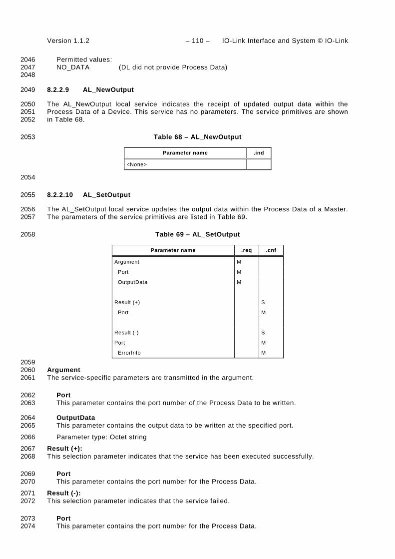
Version 1.1.2 – 110 – IO-Link Interface and System © IO-Link
Permitted values: 2046 NO_DATA (DL did not provide Process Data) 2047 2048
8.2.2.9 AL_NewOutput 2049
The AL_NewOutput local service indicates the receipt of updated output data within the 2050 Process Data of a Device. This service has no parameters. The service primitives are shown 2051 in Table 68. 2052
Table 68 – AL_NewOutput 2053
Parameter name .ind
<None>
2054
8.2.2.10 AL_SetOutput 2055
The AL_SetOutput local service updates the output data within the Process Data of a Master. 2056 The parameters of the service primitives are listed in Table 69. 2057
Table 69 – AL_SetOutput 2058
Parameter name .req .cnf
Argument M
Port M
OutputData M
Result (+) S
Port M
Result (-) S
Port M
ErrorInfo M
2059 Argument 2060 The service-specific parameters are transmitted in the argument. 2061
Port 2062 This parameter contains the port number of the Process Data to be written. 2063
OutputData 2064 This parameter contains the output data to be written at the specified port. 2065
Parameter type: Octet string 2066
Result (+): 2067 This selection parameter indicates that the service has been executed successfully. 2068
Port 2069 This parameter contains the port number for the Process Data. 2070
Result (-): 2071 This selection parameter indicates that the service failed. 2072
Port 2073 This parameter contains the port number for the Process Data. 2074

IO-Link Interface and System © IO-Link – 111 – Version 1.1.2
ErrorInfo 2075 This parameter contains error information. 2076
Permitted values: 2077 STATE_CONFLICT (Service unavailable within current state) 2078
2079
8.2.2.11 AL_Event 2080
The AL_Event service indicates up to 6 pending status or error messages. The source of one 2081 Event can be local (Master) or remote (Device). The Event can be triggered by a 2082 communication layer or by an application. The parameters of the service primitives are listed 2083 in Table 70. 2084
Table 70 – AL_Event 2085
Parameter name .req .ind .rsp .cnf
Argument M M M M
Port M M M
EventCount M M
Event(1) Instance M M
Mode M M
Type M M
Origin M
EventCode M M
…
Event(n) Instance M M
Mode M M
Type M M
Origin M
EventCode M M
2086 Argument 2087 The service-specific parameters are transmitted in the argument. 2088
Port 2089 This parameter contains the port number of the Event data. 2090
EventCount 2091 This parameter indicates the number n (1 to 6) of Events in the Event memory. 2092
Event(x) 2093 Depending on EventCount this parameter exists n times. Each instance contains the 2094 following elements. 2095
Instance 2096 This parameter indicates the Event source. 2097 Permitted values: Application (see Table A.17) 2098 Mode 2099 This parameter indicates the Event mode. 2100 Permitted values: SINGLESHOT, APPEARS, DISAPPEARS (see Table A.20) 2101 Type 2102 This parameter indicates the Event category. 2103 Permitted values: ERROR, WARNING, NOTIFICATION (see Table A.19) 2104

Version 1.1.2 – 112 – IO-Link Interface and System © IO-Link
Origin 2105 This parameter indicates whether the Event was generated in the local communi-2106 cation section or remotely (in the Device). 2107 Permitted values: LOCAL, REMOTE 2108 EventCode 2109 This parameter contains a code identifying a certain Event. 2110 Permitted values: see Annex D 2111 2112
8.2.2.12 AL_Control 2113
The AL_Control service contains the Process Data qualifier status information transmitted to 2114 and from the Device application. The parameters of the service primitives are listed in Table 2115 71. 2116
Table 71 – AL_Control 2117
Parameter name .req .ind
Argument M M
Port C C
ControlCode M M
2118 Argument 2119 The service-specific parameters are transmitted in the argument. 2120
Port 2121 This parameter contains the number of the related port. 2122
ControlCode 2123 This parameter contains the qualifier status of the Process Data (PD). 2124
Permitted values: 2125 VALID (Input Process Data valid) 2126 INVALID (Input Process Data invalid) 2127 PDOUTVALID (Output Process Data valid, see Table 53) 2128 PDOUTINVALID (Output Process Data invalid, see Table 53) 2129
2130
8.3 Application layer protocol 2131
8.3.1 Overview 2132
Figure 7 shows that the application layer offers services for data objects which are 2133 transformed into the special communication channels of the data link layer. 2134
The application layer manages the data transfer with all its assigned ports. That means, AL 2135 service calls need to identify the particular port they are related to. 2136
8.3.2 On-request Data transfer 2137
8.3.2.1 OD state machine of the Master AL 2138
Figure 57 shows the state machine for the handling of On-request Data (OD) within the 2139 application layer. 2140
"AL_Service" represents any AL service in Table 59 related to OD. "Portx" indicates a 2141 particular port number. 2142

IO-Link Interface and System © IO-Link – 113 – Version 1.1.2
/Initialization
OnReq_Idle_0AL_Abort_Portx/T17AL_Abort_Portx/T17
Build_DL_Service_1
AL_Service_Portx/T1AL_Service_Portx/T1
Await_DL_Param_cnf_2
AL_Read[ Index <=1]/T3
AL_Write[ Index =1]/T4
AL_Write[ Index = 2 &Not_ISDU_flag]/T5
DL_RWParam[ Octets_left]/T10
AL_Service/T8
AL_Read[ Index <=1]/T3
AL_Write[ Index =1]/T4
AL_Write[ Index = 2 &Not_ISDU_flag]/T5
DL_RWParam[ Octets_left]/T10
AL_Service/T8
Await_DL_ISDU_cnf_3
AL_Read[ Index >=2 & ISDU_flag]/T6
AL_Service/T12
AL_Write[ Index >=2 &ISDU_flag]/T7
AL_Read[ Index >=2 & ISDU_flag]/T6
AL_Service/T12
AL_Write[ Index >=2 &ISDU_flag]/T7
[Argument_Error]/T2
Build_AL_cnf_4
DL_ReadParam_cnf[Completed]/T13
AL_Abort/T9
DL_WriteParam_cnf[Completed]/T14
AL_Abort/T11
DL_ISDUTransport_cnf/T15
AL_Service_Portx/T16
[Argument_Error]/T2
DL_ReadParam_cnf[Completed]/T13
AL_Abort/T9
DL_WriteParam_cnf[Completed]/T14
AL_Abort/T11
DL_ISDUTransport_cnf/T15
AL_Service_Portx/T16
2143
Figure 57 – OD state machine of the Master AL 2144
Table 72 shows the states and transitions for the OD state machine of the Master AL. 2145
Table 72 – States and transitions for the OD state machine of the Master AL 2146
STATE NAME STATE DESCRIPTION
OnReq_Idle_0 AL service invocations from the Master applications or from the SM Portx handler (see Figure 55) can be accepted within this state.
Build_DL_Service_1 Within this state AL service calls are checked and corresponding DL services are created within the subsequent states. In case of an error in the arguments of the AL service a negative AL confirmation is created and returned.
Await_DL_Param_cnf_2 Within this state the AL service call is transformed in a sequence of as many DL_ReadParam or DL_WriteParam calls as needed (Direct Parameter page access; see page communication channel in Figure 6). All asynchronously occurred AL service invocations except AL_Abort are rejected (see 3.3.7).
Await_DL_ISDU_cnf_3 Within this state the AL service call is transformed in a DL_ISDUTransport service call (see ISDU communication channel in Figure 6). All asynchronously occurred AL service invocations except AL_Abort are rejected (see 3.3.7).
Build_AL_cnf_4 Within this state an AL service confirmation is created depending on an argument error, the DL service confirmation, or an AL_Abort.
2147 TRANSITION SOURCE
STATE TARGET STATE
ACTION
T1 0 1 Memorize the port number "Portx".
T2 1 4 Prepare negative AL service confirmation.
T3 1 2 Prepare DL_ReadParam for Index 0 or 1.
T4 1 2 Prepare DL_WriteParam for Index 1.

Version 1.1.2 – 114 – IO-Link Interface and System © IO-Link
TRANSITION SOURCE STATE
TARGET STATE
ACTION
T5 1 2 Prepare DL_WriteParam for Index 2 if the Device does not support ISDU.
T6 1 3 Prepare DL_ ISDUTransport(read)
T7 1 3 Prepare DL_ ISDUTransport(write)
T8 2 2 Return negative AL service confirmation on this asynchronous service call.
T9 2 4 All current DL service actions are abandoned and a negative AL service confirmation is prepared.
T10 2 2 Call next DL_ReadParam or DL_WriteParam service if not all OD are transferred.
T11 3 4 All current DL service actions are abandoned and a negative AL service confirmation is prepared.
T12 3 3 Return negative AL service confirmation on this asynchronous service call.
T13 2 4 Prepare positive AL service confirmation.
T14 2 4 Prepare positive AL service confirmation.
T15 3 4 Prepare positive AL service confirmation.
T16 4 0 Return positive AL service confirmation with port number "Portx".
T17 0 0 Return negative AL service confirmation with port number "Portx". 2148
INTERNAL ITEMS TYPE DEFINITION
Argument_Error Bool Illegal values within the service body, for example "Port number or Index out of range"
DL_RWParam Label "DL_RWParam": DL_WriteParam_cnf or DL_ReadParam_cnf
Completed Bool No more OD left for transfer
Octets_left Bool More OD for transfer
Portx Variable Service body variable indicating the port number
ISDU_Flag Bool Device supports ISDU
AL_Service Label "AL_Service" represents any AL service in Table 59 related to OD
2149
8.3.2.2 OD state machine of the Device AL 2150
Figure 58 shows the state machine for the handling of On-request Data (OD) within the 2151 application layer of a Device. 2152
/Initialization
Idle_0
AL_Abort/T11AL_Abort/T11
DL_WriteParam_ind/T1Await_AL_Write_rsp_1
AL_Write_rsp/T2
DL_WriteParam_ind/T1
AL_Write_rsp/T2
Await_AL_Read_rsp_2
DL_ReadParam_ind/T3
AL_Read_rsp/T4
DL_ReadParam_ind/T3
AL_Read_rsp/T4
AL_Read_rsp/T7
Await_AL_RW_rsp_3
AL_Write_rsp/T8
AL_Abort/T9
DL_ISDUAbort/T10
DL_ISDUTransport_ind[DirRead]/T5
DL_ISDUTransport_ind[DirWrite]/T6
AL_Read_rsp/T7
AL_Write_rsp/T8
AL_Abort/T9
DL_ISDUAbort/T10
DL_ISDUTransport_ind[DirRead]/T5
DL_ISDUTransport_ind[DirWrite]/T6
2153
Figure 58 – OD state machine of the Device AL 2154

IO-Link Interface and System © IO-Link – 115 – Version 1.1.2
Table 73 shows the states and transitions for the OD state machine of the Device AL. 2155
Table 73 – States and transitions for the OD state machine of the Device AL 2156
STATE NAME STATE DESCRIPTION
Idle_0 The Device AL is waiting on subordinated DL service calls triggered by Master messages.
Await_AL_Write_rsp_1 The Device AL is waiting on a response from the technology specific application (write access to Direct Parameter page).
Await_AL_Read_rsp_2 The Device AL is waiting on a response from the technology specific application (read access to Direct Parameter page).
Await_AL_RW_rsp_3 The Device AL is waiting on a response from the technology specific application (read or write access via ISDU).
2157 TRANSITION SOURCE
STATE TARGET STATE
ACTION
T1 0 1 Invoke AL_Write.
T2 1 0 Invoke DL_WriteParam (16 to 31).
T3 0 2 Invoke AL_Read.
T4 2 0 Invoke DL_ReadParam (0 to 31).
T5 0 3 Invoke AL_Read.
T6 0 3 Invoke AL_Write.
T7 3 0 Invoke DL_ ISDUTransport(read)
T8 3 0 Invoke DL_ ISDUTransport(write)
T9 3 0 Current AL_Read or AL_Write abandoned upon this asynchronous AL_Abort service call. Return negative DL_ ISDUTransport (see 3.3.7).
T10 3 0 Current waiting on AL_Read or AL_Write abandoned.
T11 0 0 Current DL_ ISDUTransport abandoned. All OD are set to "0". 2158
INTERNAL ITEMS TYPE DEFINITION
DirRead Bool Access direction: DL_ ISDUTransport(read) causes an AL_Read
DirWrite Bool Access direction: DL_ ISDUTransport(write) causes an AL_Read
2159
8.3.2.3 Sequence diagrams for On-request Data 2160
Figure 59 through Figure 61 demonstrate complete interactions between Master and Device 2161 for several On-request Data exchange use cases. 2162
Figure 59 demonstrates two examples for the exchange of On-request Data. For Indices > 1 2163 this is performed with the help of ISDUs and corresponding DL services (ISDU communication 2164 channel according to Figure 6). Access to Direct Parameter pages 0 and 1 uses different DL 2165 services (page communication channel according to Figure 6) 2166

Version 1.1.2 – 116 – IO-Link Interface and System © IO-Link
MasterApp
MasterAL
AL_Read_req(Index <= 1)
AL_Read_req(Index > 1)
AL_Read_cnf()
AL_Read_cnf()
AL_Read_req(Index <= 1)
AL_Read_req(Index > 1)
AL_Read_cnf()
AL_Read_cnf()
MasterDL
Portx
DL_ReadParam_req()
DL_ISDUTransport_req()
DL_ReadParam_cnf()
DL_ISDUTransport_cnf()
DL_ReadParam_req()
DL_ISDUTransport_req()
DL_ReadParam_cnf()
DL_ISDUTransport_cnf()
DeviceDL
Message()
Message()
Message()
Message()
Message()
Message()
Message()
Message()
DL_ReadParam_rsp()
DeviceAL
DL_ISDUTranspot_rsp()
DL_ReadParam_ind()
DL_ISDUTransport_ind()
DL_ReadParam_rsp()
DL_ISDUTranspot_rsp()
DL_ReadParam_ind()
DL_ISDUTransport_ind()
AL_Read_rsp()
DeviceApp
AL_Read_rsp()
AL_Read_ind(Index <=1)
AL_Read_rsp()
AL_Read_ind()
AL_Read_ind(Index <=1)
AL_Read_rsp()
AL_Read_ind()
Read Direct Parameter page 0 or 1
Read Parameter via ISDU
2167
Figure 59 – Sequence diagram for the transmission of On-request Data 2168
Figure 60 demonstrates the behaviour of On-request Data exchange in case of an error such 2169 as requested Index not available (see Table C.1). 2170
Another possible error occurs when the Master application (gateway) tries to read an Index > 2171 1 from a Device, which does not support ISDU. The Master AL would respond immediately 2172 with "NO_ISDU_SUPPORTED" as the features of the Device are acquired during start-up 2173 through reading the Direct Parameter page 1 via the parameter "M-sequence Capability" (see 2174 Table B.1). 2175
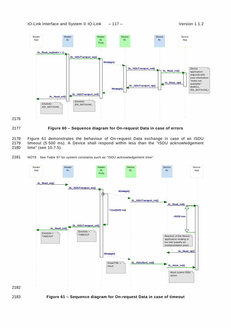
IO-Link Interface and System © IO-Link – 117 – Version 1.1.2
MasterApp
MasterAL
AL_Read_cnf()
AL_Read_req(Index > 1)
AL_Read_cnf()
AL_Read_req(Index > 1)
MasterDL
Portx
DL_ISDUTransport_req()
DL_ISDUTransport_cnf()
DL_ISDUTransport_req()
DL_ISDUTransport_cnf()
DeviceDL
Message()
Message()
Message()
Message()
DeviceAL
DL_ISDUTransport_ind()
DL_ISDUTransport_rsp()
DL_ISDUTransport_ind()
DL_ISDUTransport_rsp()
AL_Read_ind()
DeviceApp
AL_Read_ind()
AL_Read_rsp()AL_Read_rsp()
ErrorInfo:IDX_NOTAVAILErrorInfo:
IDX_NOTAVAIL
Device application responds with error information"Index not available" (0x8011, IDX_NOTAVAIL)
2176
Figure 60 – Sequence diagram for On-request Data in case of errors 2177
Figure 61 demonstrates the behaviour of On-request Data exchange in case of an ISDU 2178 timeout (5 500 ms). A Device shall respond within less than the "ISDU acknowledgement 2179 time" (see 10.7.5). 2180
NOTE See Table 97 for system constants such as "ISDU acknowledgement time". 2181
MasterApp
MasterAL
AL_Read_cnf()
AL_Read_req()
AL_Read_cnf()
AL_Read_req()
DL_ISDUTransport_cnf()
MasterDL
Portx
DL_ISDUTransport_req()
Time(5500 ms)
DL_ISDUTransport_cnf()
DL_ISDUTransport_req()
Time(5500 ms)
DeviceDL
Message()
Message()
Message()
Message()
DL_ISDUTransport_ind()
DeviceAL
DL_ISDUTransport_ind()
DL_ISDUAbort_ind()DL_ISDUAbort_ind()
AL_Read_ind()
DeviceApp
AL_Abort_ind()
AL_Read_rsp()
<5000 ms>
AL_Read_ind()
AL_Abort_ind()
AL_Read_rsp()
<5000 ms>
FlowCTRL = Abort
ErrorInfo =TIMEOUTErrorInfo =
TIMEOUT Reaction of the Device application missing or too late (usually an implementation error)
Abort current ISDU action
2182
Figure 61 – Sequence diagram for On-request Data in case of timeout 2183

Version 1.1.2 – 118 – IO-Link Interface and System © IO-Link
8.3.3 Event processing 2184
8.3.3.1 Event state machine of the Master AL 2185
Figure 62 shows the Event state machine of the Master application layer. 2186
/Initialization
Event_inactive_0
Activate/T1
Event_idle_1
Activate/T1
Deactivate/T2
AL_Event_req/T7
Deactivate/T2
AL_Event_req/T7
Read_Event_Set_2
DL_Event_ind[Diag_Portx]/T3
DL_Event_ind[Events_left]/T4
DL_Event_ind[Diag_Portx]/T3
DL_Event_ind[Events_left]/T4
DU_Event_handling_3
AL_Event_rsp/T6
DL_Event_ind[Events_done]/T5
AL_Event_rsp/T6
DL_Event_ind[Events_done]/T5
2187
Figure 62 – Event state machine of the Master AL 2188
Table 74 specifies the states and transitions of the Event state machine of the Master 2189 application layer. 2190
Table 74 – State and transitions of the Event state machine of the Master AL 2191
STATE NAME STATE DESCRIPTION
Event_inactive_0 The AL Event handling of the Master is inactive.
Event_idle_1 The Master AL is ready to accept DL_Events (diagnosis information) from the DL.
Read_Event_Set_2 The Master AL received a DL_Event_ind with diagnosis information. After this first DL_Event.ind, the AL collects the complete set (1 to 6) of DL_Events of the current EventTrigger (see 11.5).
DU_Event_handling_3 The Master AL remains in this state as long as the Diagnosis Unit (see 11.5) did not acknowledge the AL_Event.ind.
2192 TRANSITION SOURCE
STATE TARGET STATE
ACTION
T1 0 1 -
T2 1 0 -
T3 1 2 -
T4 2 2 -
T5 2 3 AL_Event.ind
T6 3 1 DL_EventConf.req
T7 1 1 AL_Event.ind

IO-Link Interface and System © IO-Link – 119 – Version 1.1.2
2193 INTERNAL ITEMS TYPE DEFINITION
Diag_Portx Bool Event set contains diagnosis information with details.
Events_done Bool Event set is processed.
Events_left Bool Event set not yet completed.
2194
8.3.3.2 Event state machine of the Device AL 2195
Figure 63 shows the Event state machine of the Device application layer 2196
/Initialization
Event_inactive_0
Activate/T1
Event_idle_1
Activate/T1
Deactivate/T2Deactivate/T2
Await_Event_response_2
AL_Event_req/T3
DL_EventTrigger_cnf/T4
AL_Event_req/T3
DL_EventTrigger_cnf/T4
2197
Figure 63 – Event state machine of the Device AL 2198
Table 75 specifies the states and transitions of the Event state machine of the Device appli-2199 cation layer. 2200
Table 75 – State and transitions of the Event state machine of the Device AL 2201
STATE NAME STATE DESCRIPTION
Event_inactive_0 The AL Event handling of the Device is inactive.
Event_idle_1 The Device AL is ready to accept AL_Events (diagnosis information) from the technology specific Device applications for the transfer to the DL. The Device applications can create new Events during this time.
Await_event_response_2 The Device AL propagated an AL_Event with diagnosis information and waits on a DL_EventTrigger confirmation of the DL. The Device AL shall not accept any new AL_Event during this time.
2202 TRANSITION SOURCE
STATE TARGET STATE
ACTION
T1 0 1 -
T2 1 0 -
T3 1 2 An AL_Event request triggers a DL_Event and the corresponding DL_EventTrigger service. The DL_Event carries the diagnosis information from AL to DL. The DL_EventTrigger sets the Event flag within the cyclic data exchange (see A.1.5)
T4 2 1 A DL_EventTrigger confirmation triggers an AL_Event confirmation. 2203
INTERNAL ITEMS TYPE DEFINITION
none

Version 1.1.2 – 120 – IO-Link Interface and System © IO-Link
8.3.3.3 Single Event scheduling 2204
Figure 64 shows how a single Event from a Device is processed, in accordance with the 2205 relevant state machines. 2206
• The Device application creates an Event request (Step 1), which is passed from the AL to 2207 the DL and buffered within the Event memory (see Table 56). 2208
• The Device AL activates the EventTrigger service to raise the Event flag, which causes 2209 the Master to read the Event from the Event memory. 2210
• The Master then propagates this Event to the gateway application (Step 2), and waits for 2211 an Event acknowledgement. 2212
• Once the Event acknowledgement is received (Step 3), it is indicated to the Device by 2213 writing to the StatusCode (Step 4). 2214
• The Device confirms the original Event request to its application (Step 5), which may now 2215 initiate a new Event request. 2216
MasterDiagnosis
Unit
MasterAL
AL_Event_ind()
AL_Event_rsp()
AL_Event_ind()
AL_Event_rsp()DL_EventConf_req()
MasterDL
Portx
DL_EventConf_req()
DL_Event_ind()
OD_req()
OD_req()
DL_Event_ind()
OD_req()
OD_req()
DeviceDL
Message()
Message()
OD_ind()
OD_ind()
Message()
Message()
Message()
Message()
OD_ind()
OD_ind()
Message()
Message()
DL_EventTrigger_req()
DeviceAL
DL_EventTrigger_req()
DL_EventTrigger_cnf()
DL_Event_req()
DL_Event_req()
DL_EventTrigger_req()
DL_EventTrigger_cnf()
DL_Event_req()
DL_Event_req()
DL_EventTrigger_req()
DeviceApp
AL_Event_req()
AL_Event_cnf()
AL_Event_req()
AL_Event_req()
AL_Event_cnf()
AL_Event_req()
Step 1: Event x occurs
Step 2: Event propagated to the gateway application
Step 3: Event acknowledged by thegateway application
Step 4: Event acknowledged to Device application
Step 5: Event x+1 occurs
Master reads event via event handler
Master writes to "StatusCode"
Event flag is set
2217
Figure 64 – Single Event scheduling 2218
8.3.3.4 Multi Event transport (legacy Devices only) 2219
Besides the method specified in 8.3.3.3 in which each single Event is conveyed through the 2220 layers and acknowledged by the gateway application, all Masters shall support a so-called 2221 "multi Event transport" which allows up to 6 Events to be transferred at a time. The Master AL 2222
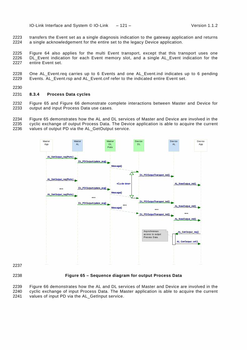
IO-Link Interface and System © IO-Link – 121 – Version 1.1.2
transfers the Event set as a single diagnosis indication to the gateway application and returns 2223 a single acknowledgement for the entire set to the legacy Device application. 2224
Figure 64 also applies for the multi Event transport, except that this transport uses one 2225 DL_Event indication for each Event memory slot, and a single AL_Event indication for the 2226 entire Event set. 2227
One AL_Event.req carries up to 6 Events and one AL_Event.ind indicates up to 6 pending 2228 Events. AL_Event.rsp and AL_Event.cnf refer to the indicated entire Event set. 2229
2230 8.3.4 Process Data cycles 2231
Figure 65 and Figure 66 demonstrate complete interactions between Master and Device for 2232 output and input Process Data use cases. 2233
Figure 65 demonstrates how the AL and DL services of Master and Device are involved in the 2234 cyclic exchange of output Process Data. The Device application is able to acquire the current 2235 values of output PD via the AL_GetOutput service. 2236
MasterApp
MasterAL
AL_SetOutput_req(Portx)
AL_SetOutput_req(Portx)
AL_SetOutput_req(Portx)
AL_SetOutput_req(Portx)
AL_SetOutput_req(Portx)
AL_SetOutput_req(Portx)
MasterDL
Portx
DL_PDOutputUpdate_req()
DL_PDOutputUpdate_req()
DL_PDOutputUpdate_req()
DL_PDOutputUpdate_req()
DL_PDOutputUpdate_req()
DL_PDOutputUpdate_req()
Message()
Dev iceDL
Message()
<Cy cle time>
Message()
Message()
Message()
<Cy cle time>
Message()
DL_PDOutputTransport_ind()
Dev iceAL
DL_PDOutputTransport_ind()
DL_PDOutputTransport_ind()
DL_PDOutputTransport_ind()
DL_PDOutputTransport_ind()
DL_PDOutputTransport_ind()
AL_NewOutput_ind()
Dev iceApp
AL_NewOutput_ind()
AL_NewOutput_ind()
AL_GetOutput_req()
AL_GetOutput_cnf ()
AL_NewOutput_ind()
AL_NewOutput_ind()
AL_NewOutput_ind()
AL_GetOutput_req()
AL_GetOutput_cnf ()
...
......
...
...
Asynchronous access to output Process Data
2237
Figure 65 – Sequence diagram for output Process Data 2238
Figure 66 demonstrates how the AL and DL services of Master and Device are involved in the 2239 cyclic exchange of input Process Data. The Master application is able to acquire the current 2240 values of input PD via the AL_GetInput service. 2241

Version 1.1.2 – 122 – IO-Link Interface and System © IO-Link
MasterApp
MasterAL
AL_NewInput_ind()
AL_NewInput_ind()
AL_GetInput_req()
AL_GetInput_cnf()
AL_NewInput_ind()
AL_NewInput_ind()
AL_NewInput_ind()
AL_GetInput_req()
AL_GetInput_cnf()
AL_NewInput_ind()
MasterDL
Portx
DL_PDInputTransport_req()
DL_PDInputTransport_req()
<Cycle time>
DL_PDInputTransport_req()
DL_PDInputTransport_req()
DL_PDInputTransport_req()
<Cycle time>
DL_PDInputTransport_req()
Message()
DeviceDL
Message()
Message()
Message()
Message()
Message()
DeviceAL
DL_PDInputUpdate_req()
DL_PDInputUpdate_cnf()
DL_PDCycle_ind()
DL_PDCycle_ind()
DL_PDCycle_ind()
DL_PDInputUpdate_req()
DL_PDInputUpdate_cnf()
DL_PDCycle_ind()
DL_PDCycle_ind()
DL_PDCycle_ind()
DeviceApp
AL_SetInput_req()
AL_SetInput_cnf()
AL_PDCycle_ind()
AL_PDCycle_ind()
AL_PDCycle_ind()
AL_SetInput_req()
AL_SetInput_cnf()
AL_PDCycle_ind()
AL_PDCycle_ind()
AL_PDCycle_ind()
... ...
......
...
Asynchronous access to input Process Data
Device application sets input Process Data for cyclic transmission by the message handler
2242
Figure 66 – Sequence diagram for input Process Data 2243
9 System management (SM) 2244
9.1 General 2245
The SDCI system management is responsible for the coordinated startup of the ports within 2246 the Master and the corresponding operations within the connected Devices. The difference 2247 between the SM of the Master and the Device is more significant than with the other layers. 2248 Consequently, the structure of this clause separates the services and protocols of Master and 2249 Device. 2250
9.2 System management of the Master 2251
9.2.1 Overview 2252
The Master system management services are used to set up the Master ports and the system 2253 for all possible operational modes. 2254
The Master SM adjusts ports through 2255
• establishing the required communication protocol revision 2256
• checking the Device compatibility (actual Device identifications match expected values) 2257
• adjusting adequate Master M-sequence types and MasterCycleTimes 2258

IO-Link Interface and System © IO-Link – 123 – Version 1.1.2
For this it uses the following services shown in Figure 67: 2259
• SM_SetPortConfig transfers the necessary Device parameters (configuration data) from 2260 Configuration Management (CM) to System Mangement (SM). The port is then started 2261 implicitly. 2262
• SM_PortMode reports the positive result of the port setup back to CM in case of correct 2263 port setup and inspection. It reports the negative result back to CM via corresponding 2264 "errors" in case of mismatching revisions and incompatible Devices. 2265
• SM_GetPortConfig reads the actual and effective parameters. 2266
• SM_Operate switches the ports into the "OPERATE" mode. 2267
Figure 67 provides an overview of the structure and services of the Master system 2268 management. 2269
The Master system management needs one application layer service (AL_Read) to acquire 2270 data (identification parameter) from special Indices for inspection. 2271
SystemManagement
Coordi-nation
SM
_Set
-P
ortC
onfig
SM
_Por
t-M
ode
SM
_Get
-P
ortC
onfig
SM
_Ope
rate
Port xHandler
MasterDL-modehandler
Messagehandler
DL_SetMode
DL_Mode
DL_Read
DL_Write
On-request Datahandler
Process Datahandler
DL-B
DL-A
PD
.req
PD
.cnf
DL_
Eve
nt
DL_
PD
Out
-pu
tUpd
ate
DL_
PD
Inpu
t-Tr
ansp
ort
DL_
Rea
d -P
aram
DL_
Writ
eP
aram
DL_
ISD
U-
Tran
spor
t
DL_
Con
trol
DL_
PD
Cyc
le
Application Layer
OD
.req
OD
.cnf
Eve
ntFl
ag
PL_Transfer.req PL_Transfer.indPL_WakeUp.req
Physical Layer (port)
Wake-up Switching signalCoded switchingInactive
PL_SetMode.req
SIODI / DO
Mode switch
AL_Read
Master applications
Gateway application (configuration, parameterization, diagnosis, on-request, and process data)
DL_
ISD
U-
Abo
rt
DL_
Eve
nt-
Con
f
MHInfo
PD
Sta
tus
Data Storage Process Data ExchangeConfiguration Manager Diagnosis UnitOn-request Data Exchange
PD
Trig
OD
Trig
2272
Figure 67 – Structure and services of the Master system management 2273
Figure 68 demonstrates the actions between the layers Master application (Master App), 2274 Configuration Management (CM), System Management (SM), Data Link (DL) and Application 2275 Layer (AL) for the startup use case of a particular port. 2276
This particular use case is characterized by the following statements: 2277
• The Device for the available configuration is connected and inspection is successful 2278
• The Device uses the correct protocol version according to this specification 2279
• The configured InspectionLevel is "type compatible" (SerialNumber is read out of the 2280 Device and not checked). 2281
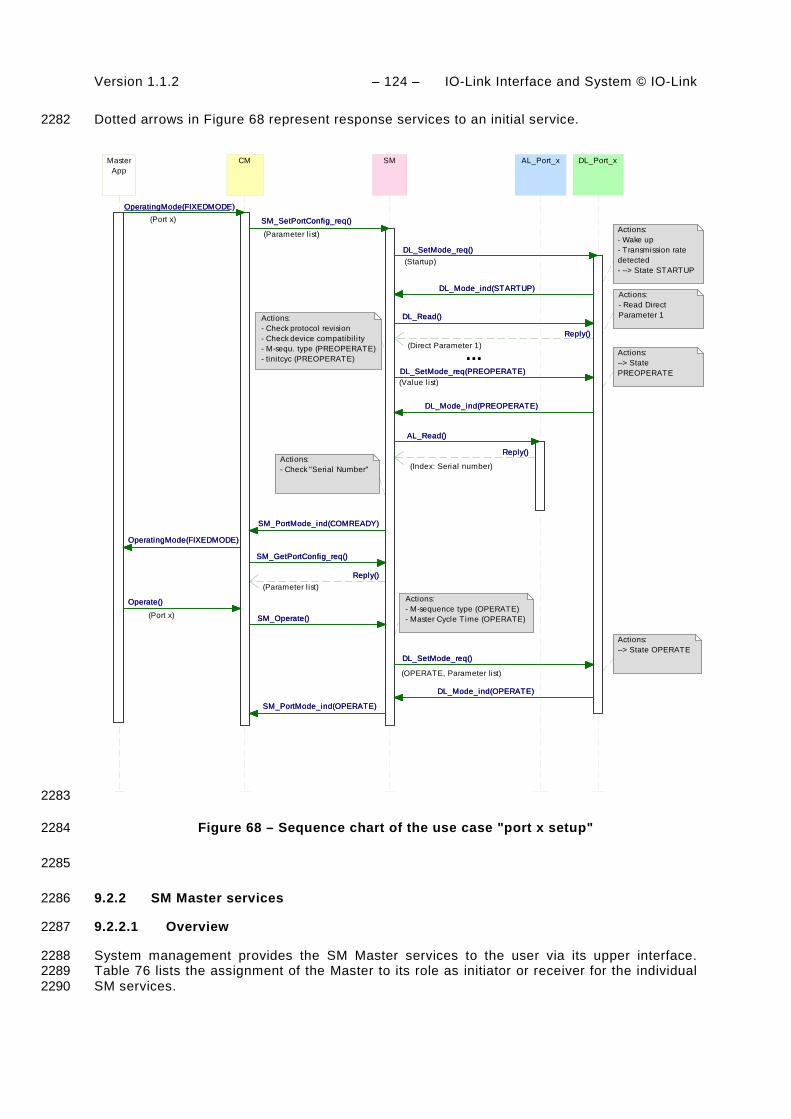
Version 1.1.2 – 124 – IO-Link Interface and System © IO-Link
Dotted arrows in Figure 68 represent response services to an initial service. 2282
CM SM
SM_GetPortConfig_req()
SM_PortMode_ind(COMREADY)
Reply()
SM_SetPortConfig_req()
SM_PortMode_ind(OPERATE)
SM_Operate()
SM_GetPortConfig_req()
SM_PortMode_ind(COMREADY)
Reply()
SM_SetPortConfig_req()
SM_PortMode_ind(OPERATE)
SM_Operate()
DL_SetMode_req()
DL_Port_x
DL_Mode_ind(STARTUP)
DL_SetMode_req()
DL_Read()
DL_Mode_ind(OPERATE)
DL_Mode_ind(PREOPERATE)
DL_SetMode_req(PREOPERATE)
Reply()
DL_SetMode_req()
DL_Mode_ind(STARTUP)
DL_SetMode_req()
DL_Read()
DL_Mode_ind(OPERATE)
DL_Mode_ind(PREOPERATE)
DL_SetMode_req(PREOPERATE)
Reply()
AL_Read()
AL_Port_x
Reply()
AL_Read()
Reply()
MasterApp
OperatingMode(FIXEDMODE)
OperatingMode(FIXEDMODE)
Operate()
OperatingMode(FIXEDMODE)
OperatingMode(FIXEDMODE)
Operate()
Actions:- Wake up- Transmission rate detected- --> State STARTUP
Actions:- Check protocol revision- Check device compatibil ity- M-sequ. type (PREOPERATE)- tinitcyc (PREOPERATE)
Actions:--> State PREOPERATE
(Startup)
(Parameter l ist)
(Value list)
(Index: Serial number)Actions:- Check "Serial Number"
(Parameter l ist)
(Port x)
Actions:- M-sequence type (OPERATE)- Master Cycle Time (OPERATE)
Actions:--> State OPERATE
(Port x)
(Direct Parameter 1)
Actions:- Read Direct Parameter 1
(OPERATE, Parameter l ist)
...
2283
Figure 68 – Sequence chart of the use case "port x setup" 2284
2285
9.2.2 SM Master services 2286
9.2.2.1 Overview 2287
System management provides the SM Master services to the user via its upper interface. 2288 Table 76 lists the assignment of the Master to its role as initiator or receiver for the individual 2289 SM services. 2290

IO-Link Interface and System © IO-Link – 125 – Version 1.1.2
Table 76 – SM services within the Master 2291
Service name Master
SM_SetPortConfig R
SM_GetPortConfig R
SM_PortMode I
SM_Operate R
Key (see 3.3.4) I Initiator of service R Receiver (Responder) of service
2292
9.2.2.2 SM_SetPortConfig 2293
The SM_SetPortConfig service is used to set up the requested Device configuration. The 2294 parameters of the service primitives are listed in Table 77. 2295
Table 77 – SM_SetPortConfig 2296
Parameter name .req .cnf
Argument M
ParameterList M
Result (+) S
Port Number M
Result (-) S
Port Number M
ErrorInfo M
2297 Argument 2298 The service-specific parameters are transmitted in the argument. 2299
ParameterList 2300 This parameter contains the configured port and Device parameters of a Master port. 2301
Parameter type: Record 2302
Record Elements: 2303
Port Number 2304 This parameter contains the port number 2305 ConfiguredCycleTime 2306 This parameter contains the requested cycle time for the OPERATE mode 2307 Permitted values: 2308 0 (FreeRunning) 2309 Time (see Table B.3) 2310 TargetMode 2311 This parameter indicates the requested operational mode of the port 2312 Permitted values: INACTIVE, DI, DO, CFGCOM, AUTOCOM (see Table 79) 2313 ConfiguredBaudrate: 2314 This parameter indicates the requested transmission rate 2315 2316

Version 1.1.2 – 126 – IO-Link Interface and System © IO-Link
Permitted values : 2317 AUTO (Master accepts transmission rate found during "ESTABLISHCOM") 2318 COM1 (transmission rate of COM1) 2319 COM2 (transmission rate of COM2) 2320 COM3 (transmission rate of COM3) 2321 ConfiguredRevisionID (CRID): 2322 Data length: 1 octet for the protocol version (see B.1.5) 2323 InspectionLevel: 2324 Permitted values: NO_CHECK, TYPE_COMP, IDENTICAL (see Table 78) 2325 ConfiguredVendorID (CVID) 2326 Data length: 2 octets 2327
NOTE VendorIDs are assigned by the IO-Link community 2328 ConfiguredDeviceID (CDID) 2329 Data length: 3 octets 2330 ConfiguredFunctionID (CFID) 2331 Data length: 2 octets 2332 ConfiguredSerialNumber (CSN) 2333 Data length: up to 16 octets 2334 2335
Result (+): 2336 This selection parameter indicates that the service has been executed successfully 2337
Port Number 2338 This parameter contains the port number 2339
Result (-): 2340 This selection parameter indicates that the service failed 2341
Port Number 2342 This parameter contains the port number 2343
ErrorInfo 2344 This parameter contains error information 2345
Permitted values: 2346 PARAMETER_CONFLICT (consistency of parameter set violated) 2347
2348 Table 78 specifies the coding of the different inspection levels (values of the InspectionLevel 2349 parameter) (see 9.2.3.2 and 11.8.5). 2350
Table 78 – Definition of the InspectionLevel (IL) 2351
Parameter InspectionLevel (IL)
NO_CHECK TYPE_COMP IDENTICAL
DeviceID (DID) (compatible)
- Yes (RDID=CDID) Yes (RDID=CDID)
VendorID (VID) - Yes (RVID=CVID) Yes (RVID=CVID)
SerialNumber (SN) - - Yes (RSN = CSN)
2352
Table 79 specifies the coding of the different Target Modes. 2353
2354
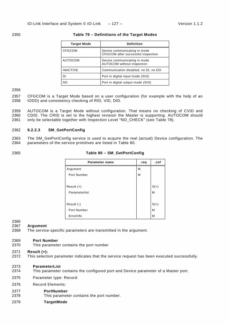
IO-Link Interface and System © IO-Link – 127 – Version 1.1.2
Table 79 – Definitions of the Target Modes 2355
Target Mode Definition
CFGCOM
Device communicating in mode CFGCOM after successful inspection
AUTOCOM Device communicating in mode AUTOCOM without inspection
INACTIVE Communication disabled, no DI, no DO
DI Port in digital input mode (SIO)
DO Port in digital output mode (SIO)
2356 CFGCOM is a Target Mode based on a user configuration (for example with the help of an 2357 IODD) and consistency checking of RID, VID, DID. 2358
AUTOCOM is a Target Mode without configuration. That means no checking of CVID and 2359 CDID. The CRID is set to the highest revision the Master is supporting. AUTOCOM should 2360 only be selectable together with Inspection Level "NO_CHECK" (see Table 78). 2361
9.2.2.3 SM_GetPortConfig 2362
The SM_GetPortConfig service is used to acquire the real (actual) Device configuration. The 2363 parameters of the service primitives are listed in Table 80. 2364
Table 80 – SM_GetPortConfig 2365
Parameter name .req .cnf
Argument M
Port Number M
Result (+) S(=)
Parameterlist M
Result (-) S(=)
Port Number M
ErrorInfo M
2366 Argument 2367 The service-specific parameters are transmitted in the argument. 2368
Port Number 2369 This parameter contains the port number 2370
Result (+): 2371 This selection parameter indicates that the service request has been executed successfully. 2372
ParameterList 2373 This parameter contains the configured port and Device parameter of a Master port. 2374
Parameter type: Record 2375
Record Elements: 2376
PortNumber 2377 This parameter contains the port number. 2378 TargetMode 2379

Version 1.1.2 – 128 – IO-Link Interface and System © IO-Link
This parameter indicates the operational mode 2380 Permitted values: INACTIVE, DI, DO, CFGCOM, AUTOCOM (see Table 79) 2381 RealBaudrate 2382 This parameter indicates the actual transmission rate 2383 Permitted values: 2384 COM1 (transmission rate of COM1) 2385 COM2 (transmission rate of COM2) 2386 COM3 (transmission rate of COM3) 2387 RealCycleTime 2388 This parameter contains the real (actual) cycle time 2389 RealRevision (RRID) 2390 Data length: 1 octet for the protocol version (see B.1.5) 2391 RealVendorID (RVID) 2392 Data length: 2 octets 2393
NOTE VendorIDs are assigned by the IO-Link community 2394 RealDeviceID (RDID) 2395 Data length: 3 octets 2396 RealFunctionID (RFID) 2397 Data length: 2 octets 2398 RealSerialNumber (RSN) 2399 Data length: up to 16 octets 2400
Result (-): 2401 This selection parameter indicates that the service failed 2402
Port Number 2403 This parameter contains the port number 2404
ErrorInfo 2405 This parameter contains error information 2406
Permitted values: 2407 PARAMETER_CONFLICT (consistency of parameter set violated) 2408
All parameters shall be set to "0" if there is no information available. 2409
9.2.2.4 SM_PortMode 2410
The SM_PortMode service is used to indicate changes or faults of the local communication 2411 mode. These shall be reported to the Master application. The parameters of the service 2412 primitives are listed in Table 81. 2413
Table 81 – SM_PortMode 2414
Parameter name .ind
Argument M
Port Number M
Mode M
2415 Argument 2416 The service-specific parameters are transmitted in the argument. 2417
Port Number 2418 This parameter contains the port number 2419
Mode 2420

IO-Link Interface and System © IO-Link – 129 – Version 1.1.2
Permitted values: 2421 INACTIVE (Communication disabled, no DI, no DO) 2422 DI (Port in digital input mode (SIO)) 2423 DO (Port in digital output mode (SIO)) 2424 COMREADY (Communication established and inspection successful) 2425 SM_OPERATE (Port is ready to exchange Process Data) 2426 COMLOST (Communication failed, new wake-up procedure required) 2427 REVISION_FAULT (Incompatible protocol revision) 2428 COMP_FAULT (Incompatible Device or Legacy-Device according to the 2429 InspectionLevel) 2430 SERNUM_FAULT (Mismatching SerialNumber according to the InspectionLevel) 2431
2432
9.2.2.5 SM_Operate 2433
The SM_Operate service prompts system management to calculate the MasterCycleTimes of 2434 the ports when they are acknowledged positively with Result (+). This service is effective on 2435 all the ports. The parameters of the service primitives are listed in Table 82. 2436
Table 82 – SM_Operate 2437
Parameter name .req .cnf
Result (+) S
Result (-) S
ErrorInfo M
2438 Result (+): 2439 This selection parameter indicates that the service has been executed successfully. 2440
Result (-): 2441 This selection parameter indicates that the service failed. 2442
ErrorInfo 2443 This parameter contains error information. 2444
Permitted values: 2445 TIMING_CONFLICT (the requested combination of cycle times for the activated ports 2446 is not possible) 2447
2448
9.2.3 SM Master protocol 2449
9.2.3.1 Overview 2450
Due to the comprehensive configuration, parameterization, and operational features of SDCI 2451 the description of the behavior with the help of state diagrams becomes rather complex. 2452 Similar to the DL state machines 9.2.3 uses the possibility of submachines within the main 2453 state machines. 2454
Comprehensive compatibility check methods are performed within the submachine states. 2455 These methods are indicated by "do method" fields within the state graphs, for example in 2456 Figure 70. 2457
The corresponding decision logic is demonstrated via activity diagrams (see Figure 71, Figure 2458 72, Figure 73, and Figure 76). 2459

Version 1.1.2 – 130 – IO-Link Interface and System © IO-Link
9.2.3.2 SM Master state machine 2460
Figure 69 shows the main state machine of the System Mangement Master. Two submachines 2461 for the compatibility and serial number check are specified in subsequent sections. In case of 2462 communication disruption the system management is informed via the service DL_Mode 2463 (COMLOST). Only the SM_SetPortConfig service allows reconfiguration of a port. The service 2464 SM_Operate (effective on all ports) causes no effect in any state except in state "wait_4". 2465
PortInactive_0
/Inialization
DL_Mode_STARTUP/T1
checkCompatibil ity_1 enex_6
enex_4enex_3enex_5 enex_2
enex_1
DL_Mode_STARTUP/T1
[CompOK]/T2
waitonDLPreoperate_2
[CompOK]/T2
checkSerNum_3enex_12 enex_10
enex_11
DL_Mode_PREOPERATE/T8DL_Mode_PREOPERATE/T8
[SerNumOK]/T10
wait_4
[SerNumOK]/T10
SM_Operate/T12
SMOperate_5
SM_Operate/T12
DL_Mode_OPERATE/T13DL_Mode_OPERATE/T13
waitonDLOperate_7
[V10CompOK]/T4
DL_Mode_OPERATE/T9
[V10CompOK]/T4
DL_Mode_OPERATE/T9
InspectionFault_6
[CompFault]/T7
[RevisionFault]/T6
[V10CompFault]/T5
[SerNumFault]/T11
[CompFault]/T7
[RevisionFault]/T6
[V10CompFault]/T5
[SerNumFault]/T11 DIDO_8
DL_Mode_COMLOST/T3DL_Mode_COMLOST/T3
JoinPseudoState_9
SM_SetPortConfig[INACTIVE]/T14
SM_SetPortConfig[CFGCOM or AUTOCOM]/T15
SM_SetPortConfig[DI or DO]/T16
SM_SetPortConfig[INACTIVE]/T14
SM_SetPortConfig[CFGCOM or AUTOCOM]/T15
SM_SetPortConfig[DI or DO]/T16
2466
Figure 69 – Main state machine of the Master system management 2467
Table 83 shows the state transition tables of the Master system management. 2468
Table 83 – State transition tables of the Master system management 2469
STATE NAME STATE DESCRIPTION
PortInactive_0 No communication
CheckCompatibility_1 Port is started and revision and Device compatibility is checked. See Figure 70.
waitonDLPreoperate_2 Wait until the PREOPERATE state is established and all the On-Request handlers are started. Port is ready to communicate.
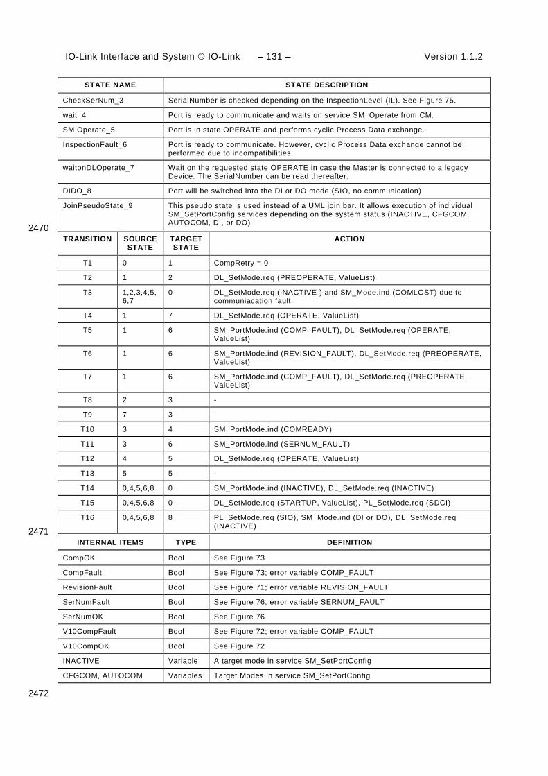
IO-Link Interface and System © IO-Link – 131 – Version 1.1.2
STATE NAME STATE DESCRIPTION
CheckSerNum_3 SerialNumber is checked depending on the InspectionLevel (IL). See Figure 75.
wait_4 Port is ready to communicate and waits on service SM_Operate from CM.
SM Operate_5 Port is in state OPERATE and performs cyclic Process Data exchange.
InspectionFault_6 Port is ready to communicate. However, cyclic Process Data exchange cannot be performed due to incompatibilities.
waitonDLOperate_7 Wait on the requested state OPERATE in case the Master is connected to a legacy Device. The SerialNumber can be read thereafter.
DIDO_8 Port will be switched into the DI or DO mode (SIO, no communication)
JoinPseudoState_9 This pseudo state is used instead of a UML join bar. It allows execution of individual SM_SetPortConfig services depending on the system status (INACTIVE, CFGCOM, AUTOCOM, DI, or DO)
2470 TRANSITION SOURCE
STATE TARGET STATE
ACTION
T1 0 1 CompRetry = 0
T2 1 2 DL_SetMode.req (PREOPERATE, ValueList)
T3 1,2,3,4,5,6,7
0 DL_SetMode.req (INACTIVE ) and SM_Mode.ind (COMLOST) due to communiacation fault
T4 1 7 DL_SetMode.req (OPERATE, ValueList)
T5 1 6 SM_PortMode.ind (COMP_FAULT), DL_SetMode.req (OPERATE, ValueList)
T6 1 6 SM_PortMode.ind (REVISION_FAULT), DL_SetMode.req (PREOPERATE, ValueList)
T7 1 6 SM_PortMode.ind (COMP_FAULT), DL_SetMode.req (PREOPERATE, ValueList)
T8 2 3 -
T9 7 3 -
T10 3 4 SM_PortMode.ind (COMREADY)
T11 3 6 SM_PortMode.ind (SERNUM_FAULT)
T12 4 5 DL_SetMode.req (OPERATE, ValueList)
T13 5 5 -
T14 0,4,5,6,8 0 SM_PortMode.ind (INACTIVE), DL_SetMode.req (INACTIVE)
T15 0,4,5,6,8 0 DL_SetMode.req (STARTUP, ValueList), PL_SetMode.req (SDCI)
T16 0,4,5,6,8 8 PL_SetMode.req (SIO), SM_Mode.ind (DI or DO), DL_SetMode.req (INACTIVE)
2471 INTERNAL ITEMS TYPE DEFINITION
CompOK Bool See Figure 73
CompFault Bool See Figure 73; error variable COMP_FAULT
RevisionFault Bool See Figure 71; error variable REVISION_FAULT
SerNumFault Bool See Figure 76; error variable SERNUM_FAULT
SerNumOK Bool See Figure 76
V10CompFault Bool See Figure 72; error variable COMP_FAULT
V10CompOK Bool See Figure 72
INACTIVE Variable A target mode in service SM_SetPortConfig
CFGCOM, AUTOCOM Variables Target Modes in service SM_SetPortConfig
2472

Version 1.1.2 – 132 – IO-Link Interface and System © IO-Link
9.2.3.3 SM Master submachine "Check Compatibility" 2473
Figure 70 shows the SM Master submachine checkCompatibility_1. 2474
checkCompatibil ity_1
CheckCompV10_21
do check comp V10
CheckComp_23
do check comp
RestartDevice_24
do write parameter
[RetryStartup]/T23
JoinPseudoState_25
ReadComParameter_20
[V10]/T20
[WriteDone]/T24
CheckVxy_22
do check revision
[<>V10]/T21
[RetryStartup]/T25
[RevisionOK]/T22
enex_6
[V10CompFault]/T5
enex_5
[V10CompOK]/T4
enex_4
[RevisionFault]/T6
enex_2
[CompOK]/T2
enex_3
[CompFault]/T7
enex_1DL_Mode_COMLOST/T3
[RetryStartup]/T23
[V10]/T20
[WriteDone]/T24
[<>V10]/T21
[RetryStartup]/T25
[RevisionOK]/T22
[V10CompFault]/T5
[V10CompOK]/T4
[RevisionFault]/T6
[CompOK]/T2
[CompFault]/T7
DL_Mode_COMLOST/T3
2475
Figure 70 – SM Master submachine CheckCompatibility_1 2476
Table 84 shows the state transition tables of the Master submachine checkCompatibility_1. 2477
Table 84 – State transition tables of the Master submachine CheckCompatibility_1 2478
STATE NAME STATE DESCRIPTION
ReadComParameter_20 Acquires communication parameters from Direct Parameter Page 1 (0x02 to 0x06) via service DL_Read (see Table B.1).
CheckCompV10_21 Acquires identification parameters from Direct Parameter Page 1 (0x07 to 0x0D) via service DL_Read (see Table B.1). The configured InspectionLevel (IL) defines the decision logic of the subsequent compatibility check "CheckCompV10" with parameters RVID, RDID, and RFID according to Figure 72.
CheckVxy_22 A check is performed whether the configured revision (CRID) matches the real (actual) revision (RRID) according to Figure 71.
CheckComp_23 Acquires identification parameters from Direct Parameter Page 1 (0x07 to 0x0D) via service DL_Read (see Table B.1). The configured InspectionLevel (IL) defines the deci-sion logic of the subsequent compatibility check "CheckComp" according to Figure 73.
RestartDevice_24 Writes the compatibility parameters configured protocol revision (CRID) and configured DeviceID (CDID) into the Device depending on the Target Mode of communication CFGCOM or AUTOCOM (see Table 79) according to Figure 74.
JoinPseudoState_25 This pseudo state is used instead of a UML join bar. No guards involved. 2479
TRANSITION SOURCE STATE
TARGET STATE
ACTION
T20 20 21 -
T21 20 22 DL_Write (0x00, MCmd_MASTERIDENT), see Table B.2
T22 22 23 -
T23 23 24 -

IO-Link Interface and System © IO-Link – 133 – Version 1.1.2
TRANSITION SOURCE STATE
TARGET STATE
ACTION
T24 24 20 -
T25 22 24 CompRetry = CompRetry +1 2480
INTERNAL ITEMS TYPE DEFINITION
CompOK Bool See Figure 73
CompFault Bool See Figure 73; error variable COMP_FAULT
RevisionFault Bool See Figure 71; error variable REVISION_FAULT
RevisionOK Bool See Figure 71
SerNumFault Bool See Figure 76; error variable SERNUM_FAULT
SerNumOK Bool See Figure 76
V10 Bool Real protocol revision of connected Device is a legacy version (V1.0, see B.1.5)
<>V10 Bool Real protocol revision of connected Device is in accordance with this standard
V10CompFault Bool See Figure 72; error variable COMP_FAULT
V10CompOK Bool See Figure 72
RetryStartup Bool See Figure 71 and Figure 73
CompRetry Variable Internal counter
WriteDone Bool Finalization of the restart service sequence
MCmd_XXXXXXX Call See Table 43
2481 Some states contain complex logic to deal with the compatibility and validity checks. Figure 2482 71 to Figure 74 are demonstrating the context. 2483
Figure 71 shows the decision logic for the protocol revision check in state "CheckVxy". In 2484 case of configured Devices the following rule applies: if the configured revision (CRID) and 2485 the real revision (RRID) do not match, the CRID will be transmitted to the Device. If the 2486 Device does not accept, the Master returns an indication via the SM_Mode service with 2487 REV_FAULT. 2488
In case of not configured Devices the operational mode AUTOCOM shall be used. See 9.2.2.2 2489 and 9.2.2.3 for the parameter name abbreviations. 2490
D1[RRID = CRID]
RevisionOK (T22)[RRID = CRID]
D2
[RRID <> CRID][RRID <> CRID]
RetryStartup (T25)[CompRetry = 0][CompRetry = 0]
[CompRetry = 1]RevisionFault (T6)
[CompRetry = 1]
2491
Figure 71 – Activity for state "CheckVxy" 2492

Version 1.1.2 – 134 – IO-Link Interface and System © IO-Link
Figure 72 shows the decision logic for the legacy compatibility check in state 2493 "CheckCompV10". 2494
V10CompOK (T4)
V10CompOK (T4)
V10CompFault (T5)
D3[IL: NO_CHECK][IL: NO_CHECK]
D4[CVID = RVID and CDID = RDID]
[IL: TYPE_COMP or IDENTICAL]
[CVID <> RVID or CDID <> RDID]
[CVID = RVID and CDID = RDID]
[IL: TYPE_COMP or IDENTICAL]
[CVID <> RVID or CDID <> RDID]
2495
Key: 2496 IL = Inspection level 2497
Figure 72 – Activity for state "CheckCompV10" 2498
2499
Figure 73 shows the decision logic for the compatibility check in state "CheckComp". 2500
CompOK (T2)
CompFault (T7)
RetryStartup (T23)
D5[IL: NO_CHECK][IL: NO_CHECK]
D6[CVID <> RVID]
[IL: TYPE_COMP or IDENTICAL]
[CVID <> RVID]
[IL: TYPE_COMP or IDENTICAL]
Device starts
Incompatible --> Error
D7[CompRetry = 0 and CDID <> RDID]
[CVID = RVID]
[CompRetry = 0 and CDID <> RDID]
[CVID = RVID]
Device restart withRVID, RDID
[CompRetry = 1 and CDID <> RDID]CompFault (T7)
[CompRetry = 1 and CDID <> RDID]Incompatible --> Error
2501
Key: 2502 IL = Inspection level 2503
Figure 73 – Activity for state "CheckComp" 2504
2505
Figure 74 shows the activity (write parameter) in state "RestartDevice". 2506

IO-Link Interface and System © IO-Link – 135 – Version 1.1.2
D8
WriteDone =FALSE
DL_Write (0x04, CRID)DL_Write (0x09…0x0B, CDID)DL_Write (0x00,0x96, "DeviceIdent")DL_Read (0x02) (dummy cycle)
[CFGCOM][CFGCOM]
[OK]
WriteDone = TRUE
[OK]
DL_Write (0x04, CRID)DL_Write (0x00,0x96, "DeviceIdent")DL_Read (0x02) (dummy cycle)
[AUTOCOM]
[OK]
[AUTOCOM]
[OK]
[CommError]
DL_Mode_COMLOST (T3)
[CommError][CommError]
DL_Mode_COMLOST (T3)
[CommError]
(T24)
2507
Figure 74 – Activity (write parameter) in state "RestartDevice" 2508
2509 9.2.3.4 SM Master submachine "Check serial number" 2510
Figure 75 shows the SM Master submachine "checkSerNum_3". This check is mandatory. 2511
checkSerNum_3
ReadSerNum_30
CheckSerNum_31
do check serial number
[SRead-]/T30
[SReadOK]/T31
enex_10
[SerNumFault]/T11
enex_11
[SerNumOK]/T10
enex_12DL_Mode_COMLOST/T3
[SRead-]/T30
[SReadOK]/T31
[SerNumFault]/T11
[SerNumOK]/T10
DL_Mode_COMLOST/T3
2512
Figure 75 – SM Master submachine CheckSerNum_3 2513
Table 85 shows the state transition tables of the Master submachine CheckSerNum_3 2514
Table 85 – State transition tables of the Master submachine CheckSerNum_3 2515
STATE NAME STATE DESCRIPTION
ReadSerNum_30 Acquires the SerialNumber from the Device via AL_Read.req (Index: 0x0015). A positive response (AL_Read(+)) leads to SReadOK = true. A negative response (AL_Read(-)) leads to SRead- = true.
CheckSerNum_31 The configured (CSN) and the real (RSN) SerialNumber are checked depending on the InspectionLevel (IL) according to Figure 76.
2516

Version 1.1.2 – 136 – IO-Link Interface and System © IO-Link
TRANSITION SOURCE STATE
TARGET STATE
ACTION
T30 40 41
T31 40 41 2517
INTERNAL ITEMS TYPE DEFINITION
SRead- Bool Negative response of service AL_Read (Index 0x0015)
SReadOK Bool SerialNumber read correctly
SERNumOK Bool See Figure 76
SERNumFault Bool See Figure 76
2518
Figure 76 shows the decision logic (activity) for the state CheckSerNum_3. 2519
SerNumOK (T10)
SerNumFault (T11)
SerNumFault (T11)
SerNumOK (T10)
D9[IL: not IDENTICAL][IL: not IDENTICAL]
D10[SRead-]
[IL: IDENTICAL]
[SRead-]
[IL: IDENTICAL]
D11[CSN <> RSN]
[SReadOK]
[CSN = RSN]
[CSN <> RSN]
[SReadOK]
[CSN = RSN]
2520
Figure 76 – Activity (check SerialNumber) for state CheckSerNum_3 2521
9.2.3.5 Rules for the usage of M-sequence types 2522
The System management is responsible for setting up the correct M-sequence types. This 2523 occurs after the check compatibility actions (transition to PREOPERATE) and before the 2524 transition to OPERATE. 2525
Different M-sequence types shall be used within the different operational states (see A.2.6). 2526 For example, when switching to the OPERATE state the M-sequence type relevant for cyclic 2527 operation shall be used. The M-sequence type to be used in operational state OPERATE is 2528 determined by the size of the input and output Process Data. The available M-sequence types 2529 in the three modes STARTUP, PREOPERATE, and OPERATE and the corresponding coding 2530 of the parameter M-sequence Capability are specified in A.2.6. The input and output data 2531 formats shall be acquired from the connected Device in order to adjust the M-sequence type. 2532 It is mandatory for a Master to implement all the specified M-sequence types in A.2.6. 2533
9.3 System management of the Device 2534
9.3.1 Overview 2535
Figure 77 provides an overview of the structure and services of the Device system 2536 management. 2537

IO-Link Interface and System © IO-Link – 137 – Version 1.1.2
DeviceDL-modehandler Message
handler
DL_Mode
Physical Layer
Application Layer
On-request Datahandler
Process Datahandler
DL-BDL-A
PL_Transfer.ind PL_Transfer.req
PD
.ind
PD
.rsp
DL_
Eve
nt
DL_
PD
Inpu
t-U
pdat
e
DL_
PD
Out
put-
Tran
spor
t
DL_
Rea
d-P
aram
DL_
Writ
e-P
aram
DL_
ISD
U-
Tran
spor
t
DL_
Con
trol
DL_
PD
Cyc
le
PL_WakeUp.indD
L_E
vent
-Tr
igge
rE
vent
Flag
DL_Read
DL_Write
PL_SetMode.req
Wake-up Switching signalCoded switching
OD
.rsp
OD
.ind
SystemManage-ment
SM
_Set
Dev
cice
Iden
t
SM
_Get
Dev
iceC
om
SM
_Dev
iceM
ode
SM
_Set
Dev
iceC
om
SM
_Get
Dev
iceI
dent
SM
_Set
Dev
iceM
ode
LineHandler
SIODI / DO
Mode switch
Data Storage (DS)
Device applications
Process Data Exchange (PDE)
Technology specific application (technology parameter, diagnosis, process data)
Parameter Manager (PM) Event Dispatcher (ED)
DL_
ISD
U-
Abo
rt
PD
InS
tatu
s
MHInfo
2538
Figure 77 – Structure and services of the system management (Device) 2539
The System Management (SM) of the Device provides the central controlling instance via the 2540 Line Handler through all the phases of initialization, default state (SIO), communication 2541 startup, communication, and fall-back to SIO mode. 2542
The Device SM interacts with the PL to establish the necessary line driver and receiver 2543 adjustments (see Figure 15), with the DL to get the necessary information from the Master 2544 (wake-up, transmission rates, a.o.) and with the Device applications to ensure the Device 2545 identity and compatibility (identification parameters). 2546
The transitions between the line handler states (see Figure 79) are initiated by the Master 2547 port activities (wake-up and communication) and triggered through the Device Data Link Layer 2548 via the DL_Mode indications and DL_Write requests (commands). 2549
The SM provides the Device identification parameters through the Device applications 2550 interface. 2551
The sequence chart in Figure 78 demonstrates a typical Device sequence from initialization to 2552 default SIO mode and via wake-up request from the Master to final communication. The 2553 sequence chart is complemented by the use case of a communication error such as TDSIO ex-2554 pired, or communication fault, or a request from Master such as Fallback (caused by Event). 2555

Version 1.1.2 – 138 – IO-Link Interface and System © IO-Link
SMDL
DL_Mode(INACTIVE)
DL_Mode(ESTABCOM)
DL_Mode(INACTIVE)
DL_Mode(ESTABCOM)
DeviceApp
SM_DeviceMode(ESTABCOM)
SM_DeviceMode(SIO)
SM_DeviceMode(IDLE)
SM_SetDeviceIdent(Initial parameter)
SM_DeviceMode(IDLE)
SM_SetDeviceIdent(Initial parameter)
SM_SetDeviceMode(SIO)
SM_SetDeviceCOM(Initial parameter)
SM_SetDeviceCom(Initial parameter)
SM_SetDeviceMode(SIO)
SM_SetDeviceMode(IDLE)
SM_DeviceMode(SIO)
PL
PL_WakeUp_ind()
PL_SetMode(DI | DO | INACTIVE)
PL_SetMode(INACTIVE)
PL_SetMode(DI | DO | INACTIVE)
PL_SetMode(COMx)
PL_SetMode(INACTIVE)
PL_WakeUp_ind()
PL_SetMode(DI | DO | INACTIVE)
PL_SetMode(INACTIVE)
PL_SetMode(DI | DO | INACTIVE)
PL_SetMode(COMx)
PL_SetMode(INACTIVE)
Device defaultcommunicationand identificationparameter
SIO mode active
WakeUp request from master
Communication startup and data exchange
Errors /events- Tdsio expired- Fallback
SIO mode active
2556
Figure 78 – Sequence chart of the use case "INACTIVE – SIO – SDCI – SIO" 2557
The SM services shown in Figure 78 are specified in 9.3.2. 2558
9.3.2 SM Device services 2559
9.3.2.1 Overview 2560
Subclause 9.3.2 describes the services the Device system management provides to its 2561 applications as shown in Figure 77. 2562
Table 86 lists the assignment of the Device to its role as initiator or receiver for the individual 2563 system management service. 2564
Table 86 – SM services within the Device 2565
Service name Device
SM_SetDeviceCom R
SM_GetDeviceCom R
SM_SetDeviceIdent R

IO-Link Interface and System © IO-Link – 139 – Version 1.1.2
Service name Device
SM_GetDeviceIdent R
SM_SetDeviceMode R
SM_DeviceMode I
Key (see 3.3.4) I Initiator of service R Receiver (Responder) of service
2566 9.3.2.2 SM_SetDeviceCom 2567
The SM_SetDeviceCom service is used to configure the communication properties supported 2568 by the Device in the system management. The parameters of the service primitives are listed 2569 in Table 87. 2570
Table 87 – SM_SetDeviceCom 2571
Parameter name .req .cnf
Argument M
ParameterList M
Result (+) S
Result (-) S
ErrorInfo M
2572 Argument 2573 The service-specific parameters are transmitted in the argument. 2574
ParameterList 2575 This parameter contains the configured communication parameters for a Device. 2576
Parameter type: Record 2577
Record Elements: 2578
SupportedSIOMode 2579 This parameter indicates the SIO mode supported by the Device. 2580 Permitted values: 2581 INACTIVE (C/Q line in high impedance), 2582 DI (C/Q line in digital input mode), 2583 DO (C/Q line in digital output mode), 2584 SupportedTransmissionrate 2585 This parameter indicates the transmission rates supported by the Device. 2586 Permitted values: 2587 COM1 (transmission rate of COM1) 2588 COM2 (transmission rate of COM2) 2589 COM3 (transmission rate of COM3) 2590 MinCycleTime 2591 This parameter contains the minimum cycle time supported by the Device (see 2592 B.1.3). 2593 M-sequence Capability 2594 This parameter indicates the capabilities supported by the Device (see B.1.4): 2595 - ISDU support 2596 - OPERATE M-sequence types 2597 - PREOPERATE M-sequence types 2598

Version 1.1.2 – 140 – IO-Link Interface and System © IO-Link
RevisionID (RID) 2599 This parameter contains the protocol revision (see B.1.5) supported by the Device. 2600 ProcessDataIn 2601 This parameter contains the length of PD to be sent to the Master (see B.1.6). 2602 ProcessDataOut 2603 This parameter contains the length of PD to be sent by the Master (see B.1.7). 2604 2605
Result (+): 2606 This selection parameter indicates that the service has been executed successfully. 2607
2608 Result (-): 2609 This selection parameter indicates that the service failed. 2610
ErrorInfo 2611 This parameter contains error information. 2612
Permitted values: 2613 PARAMETER_CONFLICT (consistency of parameter set violated) 2614 2615
9.3.2.3 SM_GetDeviceCom 2616
The SM_GetDeviceCom service is used to read the current communication properties from 2617 the system management. The parameters of the service primitives are listed in Table 88. 2618
Table 88 – SM_GetDeviceCom 2619
Parameter name .req .cnf
Argument M
Result (+) S
ParameterList M
Result (-) S
ErrorInfo M
2620 Argument 2621 The service-specific parameters are transmitted in the argument. 2622
Result (+): 2623 This selection parameter indicates that the service has been executed successfully. 2624
ParameterList 2625 This parameter contains the configured communication parameter for a Device. 2626
Parameter type: Record 2627
Record Elements: 2628
CurrentMode 2629 This parameter indicates the current SIO or Communication Mode by the Device. 2630 Permitted values: 2631 INACTIVE (C/Q line in high impedance) 2632 DI (C/Q line in digital input mode) 2633 DO (C/Q line in digital output mode) 2634 COM1 (transmission rate of COM1) 2635

IO-Link Interface and System © IO-Link – 141 – Version 1.1.2
COM2 (transmission rate of COM2) 2636 COM3 (transmission rate of COM3) 2637 MasterCycleTime 2638 This parameter contains the MasterCycleTime to be set by the Master system 2639 management (see B.1.3). This parameter is only valid in the state SM_Operate. 2640 M-sequence Capability 2641 This parameter indicates the current M-sequence capabilities configured in the 2642 system management of the Device (see B.1.4). 2643 - ISDU support 2644 - OPERATE M-sequence types 2645 - PREOPERATE M-sequence types 2646 RevisionID (RID) 2647 This parameter contains the current protocol revision (see B.1.5) within the system 2648 management of the Device. 2649 ProcessDataIn 2650 This parameter contains the current length of PD to be sent to the Master (see 2651 B.1.6). 2652 ProcessDataOut 2653 This parameter contains the current length of PD to be sent by the Master (see 2654 B.1.7). 2655 2656
Result (-): 2657 This selection parameter indicates that the service failed. 2658
ErrorInfo 2659 This parameter contains error information. 2660
Permitted values: 2661 STATE_CONFLICT (service unavailable within current state) 2662 2663
9.3.2.4 SM_SetDeviceIdent 2664
The SM_SetDeviceIdent service is used to configure the Device identification data in the 2665 system management. The parameters of the service primitives are listed in Table 89. 2666
Table 89 – SM_SetDeviceIdent 2667
Parameter name .req .cnf
Argument M
ParameterList M
Result (+) S
Result (-) S
ErrorInfo M
2668 Argument 2669 The service-specific parameters are transmitted in the argument. 2670
ParameterList 2671 This parameter contains the configured identification parameter for a Device. 2672
Parameter type: Record 2673
Record Elements: 2674

Version 1.1.2 – 142 – IO-Link Interface and System © IO-Link
VendorID (VID) 2675 This parameter contains the VendorID assigned to a Device (see B.1.8) 2676 Data length: 2 octets 2677 DeviceID (DID) 2678 This parameter contains one of the assigned DeviceIDs (see B.1.9) 2679 Data length: 3 octets 2680 FunctionID (FID) 2681 This parameter contains one of the assigned FunctionIDs (see B.1.10). 2682 Data length: 2 octets 2683 2684
Result (+): 2685 This selection parameter indicates that the service has been executed successfully. 2686
Result (-): 2687 This selection parameter indicates that the service failed. 2688
ErrorInfo 2689 This parameter contains error information. 2690
Permitted values: 2691 STATE_CONFLICT (service unavailable within current state) 2692 PARAMETER_CONFLICT (consistency of parameter set violated) 2693 2694
9.3.2.5 SM_GetDeviceIdent 2695
The SM_GetDeviceIdent service is used to read the Device identification parameter from the 2696 system management. The parameters of the service primitives are listed in Table 90. 2697
Table 90 – SM_GetDeviceIdent 2698
Parameter name .req .cnf
Argument M
Result (+) S
ParameterList M
Result (-) S
ErrorInfo M
2699 Argument 2700 The service-specific parameters are transmitted in the argument. 2701
Result (+): 2702 This selection parameter indicates that the service has been executed successfully. 2703
ParameterList 2704 This parameter contains the configured communication parameters of the Device. 2705
Parameter type: Record 2706
Record Elements: 2707
VendorID (VID) 2708 This parameter contains the actual VendorID of the Device (see B.1.8) 2709 Data length: 2 octets 2710

IO-Link Interface and System © IO-Link – 143 – Version 1.1.2
DeviceID (DID) 2711 This parameter contains the actual DeviceID of the Device (see B.1.9) 2712 Data length: 3 octets 2713 FunctionID (FID) 2714 This parameter contains the actual FunctionID of the Device (see B.1.10). 2715 Data length: 2 octets 2716
2717 Result (-): 2718 This selection parameter indicates that the service failed. 2719
ErrorInfo 2720 This parameter contains error information. 2721
Permitted values: 2722 STATE_CONFLICT (service unavailable within current state) 2723 2724
9.3.2.6 SM_SetDeviceMode 2725
The SM_SetDeviceMode service is used to set the Device into a defined operational state 2726 during initialization. The parameters of the service primitives are listed in Table 91. 2727
Table 91 – SM_SetDeviceMode 2728
Parameter name .req .cnf
Argument M
Mode M
Result (+) S
Result (-) S
ErrorInfo M
2729 Argument 2730 The service-specific parameters are transmitted in the argument. 2731
Mode 2732 Permitted values: 2733 IDLE (Device changes to waiting for configuration) 2734 SIO (Device changes to the mode defined in service "SM_SetDeviceCom") 2735
Result (+): 2736 This selection parameter indicates that the service has been executed successfully. 2737
Result (-): 2738 This selection parameter indicates that the service failed. 2739
ErrorInfo 2740 This parameter contains error information. 2741
Permitted values: 2742 STATE_CONFLICT (service unavailable within current state) 2743 2744

Version 1.1.2 – 144 – IO-Link Interface and System © IO-Link
9.3.2.7 SM_DeviceMode 2745
The SM_DeviceMode service is used to indicate changes of communication states to the 2746 Device application. The parameters of the service primitives are listed in Table 92. 2747
Table 92 – SM_DeviceMode 2748
Parameter name .ind
Argument M
Mode M
2749 Argument 2750 The service-specific parameters are transmitted in the argument. 2751
Mode 2752 Permitted values: 2753 IDLE (Device changed to waiting for configuration) 2754 SIO (Device changed to the mode defined in service "SM_SetDeviceCom") 2755 ESTABCOM (Device changed to the SM mode "SM_ComEstablish") 2756 COM1 (Device changed to the COM1 mode) 2757 COM2 (Device changed to the COM2 mode) 2758 COM3 (Device changed to the COM3 mode) 2759 STARTUP (Device changed to the STARTUP mode) 2760 IDENT_STARTUP (Device changed to the SM mode "SM_IdentStartup") 2761 IDENT_CHANGE (Device changed to the SM mode "SM_IdentCheck") 2762 PREOPERATE (Device changed to the PREOPERATE mode) 2763 OPERATE (Device changed to the OPERATE mode) 2764
2765
9.3.3 SM Device protocol 2766
9.3.3.1 Overview 2767
The behaviour of the Device is mainly driven by Master messages. 2768
9.3.3.2 SM Device state machine 2769
Figure 79 shows the SM line handler state machine of the Device. It is triggered by the 2770 DL_Mode handler and the Device application. It evaluates the different communication phases 2771 during startup and controls the line state of the Device. 2772
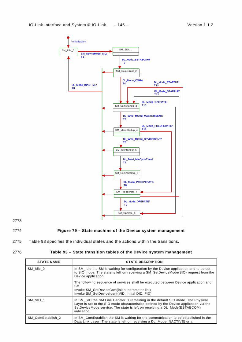
IO-Link Interface and System © IO-Link – 145 – Version 1.1.2
/Initialization
SM_Idle_0SM_DeviceMode_SIO/T1
SM_SIO_1
SM_DeviceMode_SIO/T1
SM_ComEstabl_2
DL_Mode_ESTABCOM/T2DL_Mode_ESTABCOM/T2
SM_ComStartup_3
DL_Mode_COMx/T4DL_Mode_COMx/T4
DL_Write_MCmd_MASTERIDENT/T5
SM_IdentStartup_4
DL_Write_MCmd_MASTERIDENT/T5
SM_IdentCheck_5
DL_Write_MCmd_DEVICEIDENT/T6DL_Write_MCmd_DEVICEIDENT/T6
SM_CompStartup_6
DL_Read_MinCycleTime/T7DL_Read_MinCycleTime/T7
SM_Preoperate_7
DL_Mode_PREOPERATE/T8
DL_Mode_PREOPERATE/T10
DL_Mode_STARTUP/T12
DL_Mode_PREOPERATE/T8
DL_Mode_PREOPERATE/T10
DL_Mode_STARTUP/T12
DL_Mode_OPERATE/T9
SM_Operate_8
DL_Mode_OPERATE/T9
DL_Mode_OPERATE/T11
DL_Mode_STARTUP/T13
DL_Mode_OPERATE/T11
DL_Mode_STARTUP/T13DL_Mode_INACTIVE/
T3DL_Mode_INACTIVE/T3
2773
Figure 79 – State machine of the Device system management 2774
Table 93 specifies the individual states and the actions within the transitions. 2775
Table 93 – State transition tables of the Device system management 2776
STATE NAME STATE DESCRIPTION
SM_Idle_0 In SM_Idle the SM is waiting for configuration by the Device application and to be set to SIO mode. The state is left on receiving a SM_SetDeviceMode(SIO) request from the Device application
The following sequence of services shall be executed between Device application and SM. Invoke SM_SetDeviceCom(initial parameter list) Invoke SM_SetDeviceIdent(VID, initial DID, FID)
SM_SIO_1 In SM_SIO the SM Line Handler is remaining in the default SIO mode. The Physical Layer is set to the SIO mode characteristics defined by the Device application via the SetDeviceMode service. The state is left on receiving a DL_Mode(ESTABCOM) indication.
SM_ComEstablish_2 In SM_ComEstablish the SM is waiting for the communication to be established in the Data Link Layer. The state is left on receiving a DL_Mode(INACTIVE) or a

Version 1.1.2 – 146 – IO-Link Interface and System © IO-Link
STATE NAME STATE DESCRIPTION DL_Mode(COMx) indication, where COMx may be any of COM1, COM2 or COM3.
SM_ComStartup_3 In SM_ComStartup the communication parameter (Direct Parameter page 1, addresses 0x02 to 0x06) are read by the Master SM via DL_Read requests. The state is left upon reception of a DL_Mode(INACTIVE), a DL_Mode(OPERATE) indication (legacy Master only), or a DL_Write(MCmd_MASTERIDENT) request (Master in accordance with this standard).
SM_IdentStartup_4 In SM_IdentStartup the identification data (VID, DID, FID) are read and verified by the Master. In case of incompatibilities the Master SM writes the supported SDCI Revision (RID) and configured DeviceID (DID) to the Device. The state is left upon reception of a DL_Mode(INACTIVE), a DL_Mode(PREOPERATE) indication (compatibility check passed), or a DL_Write(MCmd_DEVICEIDENT) request (new compatibility requested).
SM_IdentCheck_5 In SM_IdentCheck the SM waits for new initialization of communication and identification parameters. The state is left on receiving a DL_Mode(INACTIVE) indication or a DL_Read(Direct Parameter page 1, addresses 0x02 = "MinCycleTime") request.
Within this state the Device application shall check the RID and DID parameters from the SM and set these data to the supported values. Therefore the following sequence of services shall be executed between Device application and SM. Invoke SM_GetDeviceCom(configured RID, parameter list) Invoke SM_GetDeviceIdent(configured DID, parameter list) Invoke Device application checks and provides compatibility function and parameters Invoke SM_SetDeviceCom(new supported RID, new parameter list) Invoke SM_SetDeviceIdent(new supported DID, parameter list)
SM_CompStartup_6 In SM_CompatStartup the communication and identification data are reread and verified by the Master SM. The state is left on receiving a DL_Mode(INACTIVE) or a DL_Mode(PREOPERATE) indication.
SM_Preoperate_7 During SM_Preoperate the the SerialNumber can be read and verified by the Master SM, as well as Data Storage and Device parameterization may be executed. The state is left on receiving a DL_Mode(INACTIVE), a DL_Mode(STARTUP) or a DL_Mode(OPERATE) indication.
SM_Operate_8 During SM_Operate the cyclic Process Data exchange and acyclic On-request Data transfer are active. The state is left on receiving a DL_Mode(INACTIVE) or a DL_Mode(STARTUP) indication.
2777 TRANSITION SOURCE
STATE TARGET STATE
ACTION
T1 0 1 The Device is switched to the configured SIO mode by receiving the trigger SM_SetDeviceMode.req(SIO). Invoke PL_SetMode(DI|DO|INACTIVE) Invoke SM_DeviceMode(SIO)
T2 1 2 The Device is switched to the communication mode by receiving the trigger DL_Mode.ind(ESTABCOM). Invoke PL_SetMode(COMx) Invoke SM_DeviceMode(ESTABCOM)
T3 2,3,4,5,6,7,8
0 The Device is switched to SM_Idle mode by receiving the trigger DL_Mode.ind(INACTIVE) . Invoke PL_SetMode(INACTIVE) Invoke SM_DeviceMode(IDLE)
T4 2 3 The Device application receives an indication on the baudrate with which the communication has been established in the DL triggered by DL_Mode.ind(COMx). Invoke SM_DeviceMode(COMx)
T5 3 4 The Device identification phase is entered by receiving the trigger DL_Write.ind(MCmd_MASTERIDENT). Invoke SM_DeviceMode(IDENTSTARTUP)
T6 4 5 The Device identity check phase is entered by receiving the trigger DL_Write.ind(MCmd_DEVICEIDENT). Invoke SM_DeviceMode(IDENTCHANGE)
T7 5 6 The Device compatibility startup phase is entered by receiving the trigger DL_Read.ind( Direct Parameter page 1, address 0x02 = "MinCycleTime").
T8 6 7 The Device's preoperate phase is entered by receiving the trigger DL_Mode.ind(PREOPERATE). Invoke SM_DeviceMode(PREOPERATE)

IO-Link Interface and System © IO-Link – 147 – Version 1.1.2
TRANSITION SOURCE STATE
TARGET STATE
ACTION
T9 7 8 The Device's operate phase is entered by receiving the trigger DL_Mode.ind(OPERATE). Invoke SM_DeviceMode(OPERATE)
T10 4 7 The Device's preoperate phase is entered by receiving the trigger DL_Mode.ind(PREOPERATE). Invoke SM_DeviceMode(PREOPERATE)
T11 3 8 The Device's operate phase is entered by receiving the trigger DL_Mode.ind(OPERATE). Invoke SM_DeviceMode(OPERATE)
T12 7 3 The Device's communication startup phase is entered by receiving the trigger DL_Mode.ind(STARTUP). Invoke SM_DeviceMode(STARTUP)
T13 8 3 The Device's communication startup phase is entered by receiving the trigger DL_Mode.ind(STARTUP). Invoke SM_DeviceMode(STARTUP)
2778 INTERNAL ITEMS TYPE DEFINITION
COMx Variable Any of COM1, COM2, or COM3 transmission rates
DL_Write_MCmd_xxx Service DL Service writes MasterCommands (xxx = values out of Table B.2)
2779
Figure 80 shows a typical sequence chart for the SM communication startup of a Device 2780 matching the Master port configuration settings (regular startup). 2781

Version 1.1.2 – 148 – IO-Link Interface and System © IO-Link
SMAL DeviceApp
AL_Read()
SM_DeviceMode(COMx)
SM_DeviceMode(IDENTSTARTUP)
SM_DeviceMode(OPERATE)
SM_DeviceMode(PREOPERATE)
AL_Read()
AL_Read()
SM_DeviceMode(COMx)
SM_DeviceMode(IDENTSTARTUP)
SM_DeviceMode(OPERATE)
SM_DeviceMode(PREOPERATE)
AL_Read()
DL
DL_Write(0x00, MCmd_MASTERIDENT)
DL_ISDUTransport()
DL_Mode(COMx)
DL_Write(0x01, "MasterCycleTime")
DL_Read(Direct Parameter 1)
DL_Write(0x00, MCmd_OPERATE)
DL_Write(0x00, MCmd_PREOPERATE)
DL_ISDUTransport()
DL_Read(Direct Parameter 1)
DL_Write(0x00, MCmd_MASTERIDENT)
DL_ISDUTransport()
DL_Mode(COMx)
DL_Write(0x01, "MasterCycleTime")
DL_Read(Direct Parameter 1)
DL_Write(0x00, MCmd_OPERATE)
DL_Write(0x00, MCmd_PREOPERATE)
DL_ISDUTransport()
DL_Read(Direct Parameter 1)
From now on:PREOPERATEstate
Master actions (optional):- Check RID, VID, DID,FID(Use case assumes: check OK)
(MinCycleTime, MSeqCapability, RID,PDin length, PDout length)
(VID,DID,FID)
From now on:OPERATE state
Master actions (optional):- Read Serial Number- Data Storage- User parameteri- zation
(As many AL_Read and AL_Write as needed)
(As many as needed)
......
2782
Figure 80 – Sequence chart of a regular Device startup 2783
Figure 81 shows a typical sequence chart for the SM communication startup of a Device not 2784 matching the Master port configuration settings (compatibility mode). In this mode, the Master 2785 tries to overwrite the Device's identification parameters to achieve a compatible and a 2786 workable mode. 2787
The sequence chart in Figure 81 shows only the actions until the PREOPERATE state. The 2788 remaining actions until the OPERATE state can be taken from Figure 80. 2789
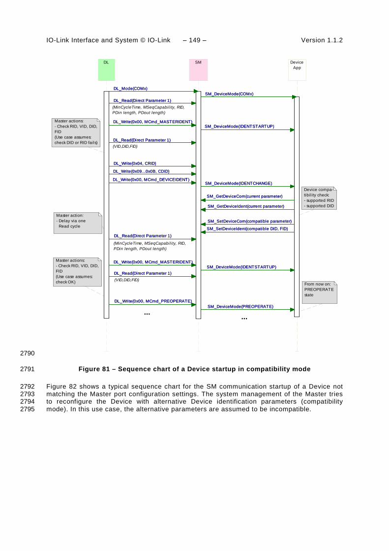
IO-Link Interface and System © IO-Link – 149 – Version 1.1.2
SM DeviceApp
SM_SetDeviceIdent(compatible DID, FID)
SM_DeviceMode(IDENTCHANGE)
SM_DeviceMode(IDENTSTARTUP)
SM_DeviceMode(PREOPERATE)
SM_DeviceMode(IDENTSTARTUP)
SM_SetDeviceCom(compatible parameter)
SM_DeviceMode(COMx)
SM_GetDeviceIdent(current parameter)
SM_GetDeviceCom(current parameter)
SM_SetDeviceIdent(compatible DID, FID)
SM_DeviceMode(IDENTCHANGE)
SM_DeviceMode(IDENTSTARTUP)
SM_DeviceMode(PREOPERATE)
SM_DeviceMode(IDENTSTARTUP)
SM_SetDeviceCom(compatible parameter)
SM_DeviceMode(COMx)
SM_GetDeviceIdent(current parameter)
SM_GetDeviceCom(current parameter)
DL
DL_Read(Direct Parameter 1)
DL_Write(0x00, MCmd_MASTERIDENT)
DL_Read(Direct Parameter 1)
DL_Write(0x09...0x0B, CDID)
DL_Mode(COMx)
DL_Read(Direct Parameter 1)
DL_Write(0x00, MCmd_MASTERIDENT)
DL_Write(0x00, MCmd_DEVICEIDENT)
DL_Write(0x00, MCmd_PREOPERATE)
DL_Write(0x04, CRID)
DL_Read(Direct Parameter 1)
DL_Read(Direct Parameter 1)
DL_Write(0x00, MCmd_MASTERIDENT)
DL_Read(Direct Parameter 1)
DL_Write(0x09...0x0B, CDID)
DL_Mode(COMx)
DL_Read(Direct Parameter 1)
DL_Write(0x00, MCmd_MASTERIDENT)
DL_Write(0x00, MCmd_DEVICEIDENT)
DL_Write(0x00, MCmd_PREOPERATE)
DL_Write(0x04, CRID)
DL_Read(Direct Parameter 1)
Device compa-tibil ity check:- supported RID- supported DID
Master actions:- Check RID, VID, DID,FID(Use case assumes: check DID or RID fails)
(MinCycleTime, MSeqCapability, RID,PDin length, PDout length)
(VID,DID,FID)
From now on:PREOPERATEstate
Master action:- Delay via one Read cycle
(MinCycleTime, MSeqCapability, RID,PDin length, PDout length)
(VID,DID,FID)
Master actions:- Check RID, VID, DID,FID(Use case assumes: check OK)
... ...
2790
Figure 81 – Sequence chart of a Device startup in compatibility mode 2791
Figure 82 shows a typical sequence chart for the SM communication startup of a Device not 2792 matching the Master port configuration settings. The system management of the Master tries 2793 to reconfigure the Device with alternative Device identification parameters (compatibility 2794 mode). In this use case, the alternative parameters are assumed to be incompatible. 2795

Version 1.1.2 – 150 – IO-Link Interface and System © IO-Link
SM DeviceApp
SM_SetDeviceCom(supported parameter)
SM_DeviceMode(COMx)
SM_DeviceMode(IDENTSTARTUP)
SM_DeviceMode(IDENTCHANGE)
SM_GetDeviceCom(current parameter)
SM_GetDeviceIdent(current parameter)
SM_DeviceMode(IDENTSTARTUP)
SM_SetDeviceIdent(supported DID, FID)
SM_SetDeviceCom(supported parameter)
SM_DeviceMode(COMx)
SM_DeviceMode(IDENTSTARTUP)
SM_DeviceMode(IDENTCHANGE)
SM_GetDeviceCom(current parameter)
SM_GetDeviceIdent(current parameter)
SM_DeviceMode(IDENTSTARTUP)
SM_SetDeviceIdent(supported DID, FID)
DL
DL_Read(Direct Parameter page 1)
DL_Write(0x00, MCmd_MASTERIDENT)
DL_Write(0x00, MCmd_DEVICEIDENT)
DL_Mode(COMx)
DL_Read(Direct Parameter page 1)
DL_Write(0x04, CRID)
DL_Write(0x09...0x0B, CDID)
DL_Read(Direct Parameter page 1)
DL_Write(0x00, MCmd_MASTERIDENT)
DL_Read(Direct Parameter page 1)
DL_Read(Direct Parameter page 1)
DL_Write(0x00, MCmd_MASTERIDENT)
DL_Write(0x00, MCmd_DEVICEIDENT)
DL_Mode(COMx)
DL_Read(Direct Parameter page 1)
DL_Write(0x04, CRID)
DL_Write(0x09...0x0B, CDID)
DL_Read(Direct Parameter page 1)
DL_Write(0x00, MCmd_MASTERIDENT)
DL_Read(Direct Parameter page 1)
Device compa-tibil ity check:- not supported RID- not supported DID
Master actions:- Check RID, VID, DID,FID(Use case assumes: check DID or RID fails)
(MinCycleTime, MSeqCapability, RID,PDin length, PDout length)
(VID,DID,FID)
Master action:- Delay via one Read cycle
(MinCycleTime, MSeqCapability, RID,PDin length, PDout length)
(VID,DID,FID)
Master actions:- Check RID, VID, DID,FID(Use case assumes: check DID or RID fails)
... ...
2796
Figure 82 – Sequence chart of a Device startup when compatibility fails 2797
2798
2799

IO-Link Interface and System © IO-Link – 151 – Version 1.1.2
10 Device 2800
10.1 Overview 2801
Figure 83 provides an overview of the complete structure and services of a Device. 2802
DeviceDL-modehandler Message
handler
DL_Mode
On-request Datahandler
Process Datahandler
DL-BDL-A
PL_Transfer.ind PL_Transfer.req
PD
.ind
PD
.rsp
DL_
Eve
nt
DL_
PD
Inpu
t-U
pdat
e
DL_
PD
Out
put-
Tran
spor
t
DL_
Rea
d-P
aram
DL_
Writ
e-P
aram
DL_
ISD
U-
Tran
spor
t
DL_
Con
trol
DL_
PD
Cyc
le
PL_WakeUp.ind
DL_
Eve
nt-
Trig
ger
DL_Read
DL_Write
Systemmanage-ment
SM
_Set
Dev
cice
Iden
t
SM
_Get
Dev
iceC
om
SM
_Dev
iceM
ode
SM
_Set
Dev
iceC
om
SM
_Get
Dev
iceI
dent
PL_SetMode.req
SM
_Set
Dev
iceM
ode
LineHandler
Wake-up Switching signalCoded switching
Mode switch
Physical layer
SIO:DI / DO
SIO:DI / DO
Eve
ntFl
ag
OD
.rsp
OD
.ind
Application LayerProcess Data
objectsOn-request Data
objects AL
AL_
Rea
d
AL_
Writ
e
AL_
Abo
rt
AL_
Con
trol
AL_
Eve
nt
AL_
Set
Inpu
t
AL_
Get
Out
put
AL_
New
Out
put
AL_
PD
Cyc
le
Data Storage (DS)
Device applications
Process Data Exchange (PDE)
Technology specific application (technology parameter, diagnosis, process data)
Parameter Manager (PM) Event Dispatcher (ED)
DL_
ISD
U-
Abo
rt
PD
InS
tatu
s
MHInfo
2803
Figure 83 – Structure and services of a Device 2804
The Device applications comprise first the technology specific application consisting of the 2805 transducer with its technology parameters, its diagnosis information, and its Process Data. 2806 The common Device applications comprise: 2807
• Parameter Manager (PM), dealing with compatibility and correctness checking of complete 2808 sets of technology (vendor) specific and common system parameters (see 10.3); 2809
• Data Storage (DS) mechanism, which optionally uploads or downloads parameters to the 2810 Master (see 10.4); 2811
• Event Dispatcher (ED), supervising states and conveying diagnosis information such as 2812 notifications, warnings, errors, and Device requests as peripheral initiatives (see 10.5); 2813
• Process Data Exchange (PDE) unit, conditioning the data structures for transmission in 2814 case of a sensor or preparing the received data structures for signal generation. It also 2815 controls the operational states to ensure the validity of Process Data (see 10.2). 2816
These Device applications provide standard methods/functions and parameters common to all 2817 Devices, and Device specific functions and parameters, all specified within Clause 10. 2818

Version 1.1.2 – 152 – IO-Link Interface and System © IO-Link
10.2 Process Data Exchange (PDE) 2819
The Process Data Exchange unit cyclically transmits and receives Process Data without 2820 interference from the On-request Data (parameters, commands, and Events). 2821
An actuator (output Process Data) shall observe the cyclic transmission and enter a default 2822 appropriate state, for example keep last value, stop, or de-energize, whenever the data 2823 transmission is interrupted (see 7.3.3.5 and 10.7.3). The actuator shall wait on the 2824 MasterCommand "ProcessDataOutputOperate" (see Table B.2, output Process Data "valid") 2825 prior to regular operation after restart in case of an interruption. 2826
Within cyclic data exchange, an actuator (output Process Data) receives a Master-Command 2827 "DeviceOperate", whenever the output Process Data are invalid and a Master-Command 2828 "ProcessDataOutputOperate", whenever they become valid again (see Table B.2). 2829
There is no need for a sensor Device (input Process Data) to monitor the cyclic data 2830 exchange. However, if the Device is not able to guarantee valid Process Data, the PD status 2831 "Process Data invalid" (see A.1.5) shall be signaled to the Master application. 2832
10.3 Parameter Manager (PM) 2833
10.3.1 General 2834
A Device can be parameterized via two basic methods using the Direct Parameters or the 2835 Index memory space accessible with the help of ISDUs (see Figure 5). 2836
Mandatory for all Devices are the so-called Direct Parameters in page 1. This page 1 contains 2837 common communication and identification parameters (see B.1). 2838
Direct Parameter page 2 optionally offers space for a maximum of 16 octets of technology 2839 (vendor) specific parameters for Devices requiring not more than this limited number and with 2840 small system footprint (ISDU communication not implemented, easier fieldbus handling 2841 possible but with less comfort). Access to the Direct Parameter page 2 is performed via 2842 AL_Read and AL_Write (see 10.7.5). 2843
The transmission of parameters to and from the spacious Index memory can be performed in 2844 two ways: single parameter by single parameter or as a block of parameters. Single 2845 parameter transmission as specified in 10.3.4 is secured via several checks and confirmation 2846 of the transmitted parameter. A negative acknowledgement contains an appropriate error 2847 description and the parameter is not activated. Block parameter transmission as specified in 2848 10.3.5 defers parameter consistency checking and activation until after the complete 2849 transmission. The Device performs the checks upon reception of a special command and 2850 returns a confirmation or a negative acknowledgement with an appropriate error description. 2851 In this case the transmitted parameters shall be rejected and a roll back to the previous 2852 parameter set shall be performed to ensure proper functionality of the Device. 2853
10.3.2 Parameter manager state machine 2854
The Device can be parameterized using ISDU mechanisms whenever the PM is active. The 2855 main functions of the PM are the transmission of parameters to the Master ("Upload"), to the 2856 Device ("Download"), and the consistency and validity checking within the Device 2857 ("ValidityCheck") as demonstrated in Figure 84. 2858
The PM is driven by command messages of the Master (see Table B.9). For example the 2859 guard [UploadStart] corresponds to the reception of the SystemCommand 2860 "ParamUploadStart" and [UploadEnd] to the reception of the SystemCommand 2861 "ParamUploadEnd". 2862

IO-Link Interface and System © IO-Link – 153 – Version 1.1.2
NOTE 1 Following a communication interruption, the Master system management uses the service 2863 SM_DeviceMode with the variable "INACTIVE" to stop the upload process and to return to the "IDLE" state. 2864
Any new "ParamUploadStart" or "ParamDownloadStart" while another sequence is pending, 2865 for example due to an unexpected shut-down of a vendor parameterization tool, will abort the 2866 pending sequence. The corresponding parameter changes will be discarded. 2867
NOTE 2 A PLC user program and a parameterization tool can conflict (multiple access), for example if during 2868 commissioning, the user did not disable accesses from the PLC program while changing parameters via the tool. 2869
The parameter manager mechanism in a Device is always active and the DS_ParUpload.req 2870 in transition T4 is used to trigger the Data Storage (DS) mechanism in 10.4.2. 2871
Idle_0
/Initialization
[Single Parameter]/T1
ValidityCheck_1
[Single Parameter]/T1
[DownloadStore]/T2
[Local Parameter]/T3
[DataValid & StoreRequest]/T4
[DataValid & NotStoreRequest]/T5
[DataInvalid]/T6
[DownloadStore]/T2
[Local Parameter]/T3
[DataValid & StoreRequest]/T4
[DataValid & NotStoreRequest]/T5
[DataInvalid]/T6
[DownloadStart]/T7
Download_2[DownloadBreak]/T8
SM_DeviceMode_IDLE/T9
[DownloadEnd]/T13
[DownloadStore]/T14
[DownloadStart]/T16
[DownloadStart]/T7
[DownloadBreak]/T8
SM_DeviceMode_IDLE/T9
[DownloadEnd]/T13
[DownloadStore]/T14
[DownloadStart]/T16
[UploadStart]/T10
Upload_3
SM_DeviceMode_IDLE/T12
[UploadEnd]/T11
[UploadStart]/T15
[UploadStart]/T10SM_DeviceMode_IDLE/
T12[UploadEnd]/T11
[UploadStart]/T15
2872
Figure 84 – The Parameter Manager (PM) state machine 2873
Table 94 shows the state transition tables of the Device Parameter Manager (PM) state 2874 machine. 2875
Table 94 – State transition tables of the PM state machine 2876
STATE NAME STATE DESCRIPTION
Idle_0 Waiting on parameter transmission
ValidityCheck_1 Check of consistency and validity of current parameter set.
Download_2 Parameter download active; local parameterization locked (e.g. teach-in)
Upload_3 Parameter upload active; parameterization globally locked; all write accesses for parameter changes via tools shall be rejected (ISDU ErrorCode "Service temporarily not available – Device control")
2877 TRANSITION SOURCE
STATE TARGET STATE
ACTION
T1 0 1 -
T2 0 1 Set "StoreRequest" (= TRUE)
T3 0 1 Set "StoreRequest" (= TRUE)
T4 1 0 Mark parameter set as valid; invoke DS_ParUpload.req to DS; enable

Version 1.1.2 – 154 – IO-Link Interface and System © IO-Link
TRANSITION SOURCE STATE
TARGET STATE
ACTION
positive acknowledge of transmission; reset "StoreRequest" (= FALSE)
T5 1 0 Mark parameter set as valid; enable positive acknowledge of transmission
T6 1 0 Mark parameter set as invalid; enable negative acknowledge of transmission; reset "StoreRequest" (= FALSE); discard parameter buffer
T7 0 2 Lock local parameter access
T8 2 0 Unlock local parameter access; discard parameter buffer
T9 2 0 Unlock local parameter access; discard parameter buffer
T10 0 3 Lock local parameter access
T11 3 0 Unlock local parameter access
T12 3 0 Unlock local parameter access
T13 2 1 Unlock local parameter access
T14 2 1 Unlock local parameter access; set "StoreRequest" (= TRUE)
T15 3 3 Lock local parameter access
T16 2 2 Discard parameter buffer, so that a possible second start will not be blocked.
2878 INTERNAL ITEMS TYPE DEFINITION
DownloadStore Bool SystemCommand "ParamDownloadStore" received, see Table B.9
DataValid Bool Positive result of conformity and validity checking
DataInvalid Bool Negative result of conformity and validity checking
DownloadStart Bool SystemCommand "ParamDownloadStart" received, see Table B.9
DownloadBreak Bool SystemCommand "ParamBreak" or "ParamUploadStart" received
DownloadEnd Bool SystemCommand "ParamDownloadEnd" received, see Table B.9
StoreRequest Bool Flag for a requested Data Storage sequence, i.e. SystemCommand "ParamDownloadStore" received (= TRUE)
NotStoreRequest Bool Inverted value of StoreRequest
UploadStart Bool SystemCommand "ParamUploadStart" received, see Table B.9
UploadEnd Bool SystemCommand "ParamUploadEnd" received, see Table B.9
Single Parameter Bool In case of "single parameter" as specified in 10.3.4
Local Parameter Bool In case of "local parameter" as specified in 10.3.3
2879
The Parameter Manager (PM) supports handling of "single parameter" (Index and Subindex) 2880 transfers as well as "block parameter" transmission (entire parameter set). 2881
10.3.3 Dynamic parameter 2882
Parameters accessible through SDCI read or write services may also be changed via on-2883 board control elements (for example teach-in button) or the human machine interface of a 2884 Device. These changes shall undergo the same validity checks as a single parameter access. 2885 Thus, in case of a positive result "DataValid" in Figure 84, the "StoreRequest" flag shall be 2886 applied in order to achieve Data Storage consistency. In case of a negative result 2887 "InvalidData", the previous values of the corresponding parameters shall be restored ("roll 2888 back"). In addition, a Device specific indication on the human machine interface is 2889 recommended as a positive or negative feedback to the user. 2890
It is recommended to avoid concurrent access to a parameter via local control elements and 2891 SDCI write services at the same point in time. 2892

IO-Link Interface and System © IO-Link – 155 – Version 1.1.2
10.3.4 Single parameter 2893
Sample sequence charts for valid and invalid single parameter changes are specified in 2894 Figure 85. 2895
Positive result
Negative result
MasterApp
AL_Write_req(Parameter)
MasterAL
AL_Write_req(Parameter)
AL_Write_cnf(+)
AL_Write_req(Parameter)
AL_Write_cnf(-)
AL_Write_cnf(+)
AL_Write_req(Parameter)
AL_Write_cnf(-)
DeviceAL
SDCI_Message()
SDCI_Message()
SDCI_Message()
SDCI_Message()
SDCI_Message()
SDCI_Message()
SDCI_Message()
SDCI_Message()
AL_Write_res(+)
DeviceApp
AL_Write_res(+)
AL_Write_ind(Parameter)
AL_Write_ind(Parameter)
AL_Write_res(-)
AL_Write_ind(Parameter)
AL_Write_ind(Parameter)
AL_Write_res(-)
Parametercheck result = OK
Parametercheck failed
2896
Figure 85 – Positive and negative parameter checking result 2897
If single parameterization is performed via ISDU objects, the Device shall check the access, 2898 structure, consistency and validity (see Table 95) of the transmitted data within the context of 2899 the entire parameter set and return the result in the confirmation. The negative confirmation 2900 carries one of the error indications of Table C.2 in Annex C. 2901
Table 95 – Definitions of parameter checks 2902
Parameter check Definition Error indication
Access Check for valid access rights for this Index / Subindex, independent from data content (Index / Subindex permanent or temporarily unavailable; write access on read only Index)
See C.2.3 to C.2.8
Consistency Check for valid data content of the entire parameter set, testing for interference or correlations between parameters
See C.2.16 and C.2.17
Structure Check for valid data structure like data size, only complete data structures can be written, for example 2 octets to an UInteger16 data type
See C.2.12 and C.2.13
Validity Check for valid data content of single parameters, testing for data limits
See C.2.9 to C.2.11, C.2.14, C.2.15
2903

Version 1.1.2 – 156 – IO-Link Interface and System © IO-Link
10.3.5 Block parameter 2904
User applications such as function blocks within PLCs and parameterization tool software can 2905 use start and end commands to indicate the begin and end of a block parameter transmission. 2906 For the duration of the block parameter transmission the Device application shall inhibit all the 2907 parameter changes originating from other sources, for example local parameterization, teach-2908 in, etc. 2909
A sample sequence chart for valid block parameter changes with an optional Data Storage 2910 request is demonstrated in Figure 86. 2911
MasterApp
MasterAL
AL_Write_cnf(+)
AL_Write_cnf(+)
AL_Write_req(SysCommand)
AL_Write_req(SysCommand)
AL_Write_req(Parameter)
AL_Write_cnf(+)
AL_Write_cnf(+)
AL_Write_cnf(+)
AL_Write_req(SysCommand)
AL_Write_req(SysCommand)
AL_Write_req(Parameter)
AL_Write_cnf(+)
SDCI_Message()
DeviceAL
SDCI_Message()
SDCI_Message()
SDCI_Message()
SDCI_Message()
SDCI_Message()
SDCI_Message()
SDCI_Message()
SDCI_Message()
SDCI_Message()
SDCI_Message()
SDCI_Message()
AL_Write_ind(SysCommand)
DeviceApp
AL_Write_res(+)
AL_Write_ind(Parameter)
AL_Write_res(+)
AL_Write_ind(SysCommand)
AL_Write_res(+)
DS_ParUpload_req()
AL_Write_ind(SysCommand)
AL_Write_res(+)
AL_Write_ind(Parameter)
AL_Write_res(+)
AL_Write_ind(SysCommand)
AL_Write_res(+)
DS_ParUpload_req()
(ParamDownloadStart)
(ParamDownloadStart)
More parameter sequences as needed
(ParamDownloadStore)
(ParamDownloadStore)Parametercheck result = OK
Option:Data storageupload request
2912
Figure 86 – Positive block parameter download with Data Storage request 2913
A sample sequence chart for invalid block parameter changes is demonstrated in Figure 87. 2914
The "ParamDownloadStart" command (see Table B.9) indicates the beginning of the block 2915 parameter transmission in download direction (from user application to the Device). The 2916 SystemCommand "ParamDownloadEnd" or "ParamDownloadStore" terminates this sequence. 2917 Both functions are similar. However, in addition the SystemCommand "ParamDownloadStore" 2918

IO-Link Interface and System © IO-Link – 157 – Version 1.1.2
causes the Data Storage (DS) mechanism to upload the parameter set through the 2919 DS_UPLOAD_REQ Event (see 10.4.2). 2920
MasterApp
AL_Write_req(SysCommand)
MasterAL
AL_Write_req(SysCommand)
AL_Write_req(SysCommand)
AL_Write_cnf(-)
AL_Write_cnf(+)
AL_Write_cnf(+)
AL_Write_req(Parameter)
AL_Write_req(SysCommand)
AL_Write_cnf(-)
AL_Write_cnf(+)
AL_Write_cnf(+)
AL_Write_req(Parameter)
DeviceAL
SDCI_Message()
SDCI_Message()
SDCI_Message()
SDCI_Message()
SDCI_Message()
SDCI_Message()
SDCI_Message()
SDCI_Message()
SDCI_Message()
SDCI_Message()
SDCI_Message()
SDCI_Message()
DeviceApp
AL_Write_ind(SysCommand)
AL_Write_ind(SysCommand)
AL_Write_res(+)
AL_Write_ind(Parameter)
AL_Write_res(+)
AL_Write_res(-)
AL_Write_ind(SysCommand)
AL_Write_ind(SysCommand)
AL_Write_res(+)
AL_Write_ind(Parameter)
AL_Write_res(+)
AL_Write_res(-)
(ParamDownloadStart)
More parameter sequences as needed
(ParamDownloadEnd orParamDownloadStore)
Parametercheck failed(ParamDownloadEnd or
ParamDownloadStore)
(ParamDownloadStart)
2921
Figure 87 – Negative block parameter download 2922
During block parameter download the consistency checking for single transferred parameters 2923 shall be disabled and the parameters are not activated. With the "ParamDownloadEnd" 2924 command, the Device checks the entire parameter set and indicates the result to the 2925 originator of the block parameter transmission within the ISDU acknowledgement in return to 2926 the command. 2927
During the block parameter download the access and structure checks are always performed 2928 (see Table 95). Optionally, validity checks may also be performed. The parameter manager 2929 shall not exit from the block transfer mode in case of invalid accesses or structure violations. 2930
In case of an invalid parameter set the changed parameters shall be discarded and a rollback 2931 to the previous parameter set shall be performed. The corresponding negative confirmation 2932 shall contain one of the error indications from Table C.2. With a negative confirmation of the 2933 SystemCommand "ParamDownloadStore", the Data Storage upload request is omitted. 2934

Version 1.1.2 – 158 – IO-Link Interface and System © IO-Link
The "ParamUploadStart" command (see Table B.9) indicates the beginning of the block 2935 parameter transmission in upload direction (from the Device to the user application). The 2936 SystemCommand "ParamUploadEnd" terminates this sequence and indicates the end of 2937 transmission. 2938
A block parameter transmission is aborted if the parameter manager receives a 2939 SystemCommand "ParamBreak". In this case the block transmission quits without any 2940 changes in parameter settings. 2941
10.3.6 Concurrent parameterization access 2942
There is no mechanism to secure parameter consistency within the Device in case of 2943 concurrent accesses from different user applications above Master level. This shall be 2944 ensured or blocked on user level. 2945
10.3.7 Command handling 2946
Application commands such as teach-in or restore factory settings are conveyed in form of 2947 parameters. An application command is confirmed with a positive service response – 2948 AL_Write.res(+). A negative service response – AL_Write.res(-) – shall indicate the failed 2949 execution of the application command. In both cases the ISDU timeout limit shall be 2950 considered (see Table 97). 2951
10.4 Data Storage (DS) 2952
10.4.1 General 2953
The Data Storage (DS) mechanism enables the consistent and up-to-date buffering of the 2954 Device parameters on upper levels like PLC programs or fieldbus parameter server. Data 2955 Storage between Masters and Devices is specified within this standard, whereas the adjacent 2956 upper data storage mechanisms depend on the individual fieldbus or system. The Device 2957 holds a standardized set of objects providing information about parameters for Data Storage 2958 such as memory size requirements, control and state information of the Data Storage 2959 mechanism (see Table B.10). Revisions of Data Storage parameter sets are identified via a 2960 Parameter Checksum. 2961
The implementation of the DS mechanism specified in this standard is highly recommended 2962 for Devices. If this mechanism is not supported it is the responsibility of the Device vendor to 2963 describe how parameterization of a Device after replacement can be ensured in a system 2964 conform manner without tools. 2965
10.4.2 Data Storage state machine 2966
Any changed set of valid parameters leads to a new Data Storage upload. The upload is 2967 initiated by the Device by raising a "DS_UPLOAD_REQ" Event (see Table D.2). The Device 2968 shall store the internal state "Data Storage Upload" in non-volatile memory (see Table B.10, 2969 State Property), until it receives a Data Storage command "DS_UploadEnd" or 2970 "DS_DownloadEnd". 2971
The Device shall generate an Event "DS_UPLOAD_REQ" (see Table D.2) only if the 2972 parameter set is valid and 2973
• parameters assigned for Data Storage have been changed locally on the Device (for 2974 example teach-in, human machine interface, etc.), or 2975
• the Device receives a SystemCommand "ParamDownloadStore" 2976
With this Event information the Data Storage mechanism of the Master is triggered and 2977 initiates a Data Storage upload sequence. 2978
The state machine in Figure 88 specifies the Device Data Storage mechanism. 2979
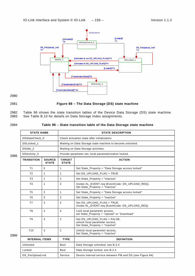
IO-Link Interface and System © IO-Link – 159 – Version 1.1.2
DSStateCheck_0
/Inialization
DSIdle_2
DS_ParUpload_ind/T7
[Unlocked]/T6
DS_ParUpload_ind/T7
[Unlocked]/T6
DSLocked_1
[Locked]/T1
[Unlocked & DS_UPLOAD_FLAG]/T4
DS_ParUpload_ind/T2
[Unlocked & not DS_UPLOAD_FLAG]/T3
[Locked]/T5
[Locked]/T1
[Unlocked & DS_UPLOAD_FLAG]/T4
DS_ParUpload_ind/T2
[Unlocked & not DS_UPLOAD_FLAG]/T3
[Locked]/T5
[TransmissionStart]/T8
DSActivity_3[TransmissionEnd]/T9
[TranmissionBreak]/T10
[TransmissionStart]/T8
[TransmissionEnd]/T9
[TranmissionBreak]/T10
2980
Figure 88 – The Data Storage (DS) state machine 2981
Table 96 shows the state transition tables of the Device Data Storage (DS) state machine. 2982 See Table B.10 for details on Data Storage Index assignments. 2983
Table 96 – State transition table of the Data Storage state machine 2984
STATE NAME STATE DESCRIPTION
DSStateCheck_0 Check activation state after initialization.
DSLocked_1 Waiting on Data Storage state machine to become unlocked.
DSIdle_2 Waiting on Data Storage activities.
DSActivity_3 Provide parameter set; local parameterization locked. 2985
TRANSITION SOURCE STATE
TARGET STATE
ACTION
T1 0 1 Set State_Property = "Data Storage access locked"
T2 1 1 Set DS_UPLOAD_FLAG = TRUE
T3 1 2 Set State_Property = "Inactive"
T4 1 2 Invoke AL_EVENT.req (EventCode: DS_UPLOAD_REQ), Set State_Property = "Inactive"
T5 2 1 Set State_Property = "Data Storage access locked"
T6 0 2 Set State_Property = "Inactive"
T7 2 2 Set DS_UPLOAD_FLAG = TRUE, invoke AL_EVENT.req (EventCode: DS_UPLOAD_REQ)
T8 2 3 Lock local parameter access, set State_Property = "Upload" or "Download"
T9 3 2 Set DS_UPLOAD_FLAG = FALSE, unlock local parameter access, Set State_Property = "Inactive"
T10 3 2 Unlock local parameter access, Set State_Property = "Inactive"
2986 INTERNAL ITEMS TYPE DEFINITION
Unlocked Bool Data Storage unlocked, see B.2.4
Locked Bool Data Storage locked, see B.2.4
DS_ParUpload.ind Service Device internal service between PM and DS (see Figure 84)

Version 1.1.2 – 160 – IO-Link Interface and System © IO-Link
INTERNAL ITEMS TYPE DEFINITION
TransmissionStart Bool DS_Command "DS_UploadStart" or "DS_DownloadStart" has been invoked
TransmissionEnd Bool DS_Command "DS_UploadEnd" or "DS_DownloadEnd" has been invoked
TransmissionBreak Bool SM_MODE_INACTIVE or DS_Command "DS_Break" received
2987 The truncated sequence chart in Figure 89 demonstrates the important communication 2988 sequences after the parameterization. 2989
MasterApp
AL_Write_cnf(+)
MasterAL
AL_Write_cnf(+)
AL_Event_ind(DS_UPLOAD_REQ)
AL_Write_req(DS_Command)
AL_Write_cnf(+)
AL_Event_ind(DS_UPLOAD_REQ)
AL_Write_req(DS_Command)
AL_Write_cnf(+)
DeviceAL
SDCI_Message()
SDCI_Message()
SDCI_Message()
SDCI_Message()
SDCI_Message()
SDCI_Message()
SDCI_Message()
SDCI_Message()
DeviceApp
AL_Write_ind(DS_Command)
AL_Event(DS_UPLOAD_REQ)
AL_Write_res(+)
AL_Write_ind(SysCommand)
AL_Write_res(+)
AL_Write_ind(DS_Command)
AL_Event(DS_UPLOAD_REQ)
AL_Write_res(+)
AL_Write_ind(SysCommand)
AL_Write_res(+)
(ParamDownloadStore) Data storage upload request active
(DS_UploadEnd orDS_DownloadEnd)
Data storage request inactive
(DS_UploadEnd orDS_DownloadEnd)
2990
Figure 89 – Data Storage request message sequence 2991
10.4.3 DS configuration 2992
The Data Storage mechanism inside the Device may be disabled via the Master, for example 2993 by a tool or a PLC program. See B.2.4 for further details. This is recommended during 2994 commissioning or system tests to avoid intensive communication. 2995
10.4.4 DS memory space 2996
To handle the requested data amount for Data Storage under any circumstances, the 2997 requested amount of indices to be saved and the required total memory space are given in 2998 the Data Storage Size parameter, see Table B.10. The required total memory space (including 2999 the structural information shall not exceed 2 048 octets (see Annex F). The Data Storage 3000 mechanism of the Master shall be able to support this amount of memory per port. 3001

IO-Link Interface and System © IO-Link – 161 – Version 1.1.2
10.4.5 DS Index_List 3002
The Device is the "owner" of the DS Index_List (see Table B.10). Its purpose is to provide all 3003 the necessary information for a Device replacement. The DS Index_List shall be fixed for any 3004 specific DeviceID. Otherwise the data integrity between Master and Device cannot be 3005 guaranteed. The Index List shall contain the termination marker (see Table B.10), if the 3006 Device does not support Data Storage (see 10.4.1). The required storage size shall be 0 in 3007 this case. 3008
10.4.6 DS parameter availability 3009
All indices listed in the Index List shall be readable and writeable between the 3010 SystemCommands "DS_UploadStart" or "DS_DownloadStart" and "DS_UploadEnd" or 3011 "DS_DownloadEnd" (see Table B.10). If one of the Indices is rejected by the Device, the Data 3012 Storage Master will abort the up- or download with a SystemCommand "DS_Break". In this 3013 case no retries of the Data Storage sequence will be performed. 3014
10.4.7 DS without ISDU 3015
The support of ISDU transmission in a Device is a precondition for the Data Storage of 3016 parameters. Parameters in Direct Parameter page 2 cannot be saved and restored by the 3017 Data Storage mechanism. 3018
10.4.8 DS parameter change indication 3019
The Parameter_Checksum specified in Table B.10 is used as an indicator for changes in a 3020 parameter set. This standard does not require a specific mechanism for detecting parameter 3021 changes. A set of recommended methods is provided in the informative Annex J. 3022
10.5 Event Dispatcher (ED) 3023
Any of the Device applications can generate predefined system status information when SDCI 3024 operations fail or technology specific information (diagnosis) as a result from technology 3025 specific diagnostic methods occur. The Event Dispatcher turns this information into an Event 3026 according to the definitions in A.6. The Event consists of an EventQualifier indicating the 3027 properties of an incident and an EventCode ID representing a description of this incident 3028 together with possible remedial measures. Table D.1 comprises a list of predefined IDs and 3029 descriptions for application oriented incidents. Ranges of IDs are reserved for profile specific 3030 and vendor specific incidents. Table D.2 comprises a list of predefined IDs for SDCI specific 3031 incidents. 3032
Events are classified in "Errors", "Warnings", and "Notifications". See 10.9.2 for these 3033 classifications and see 11.5 for how the Master is controlling and processing these Events. 3034
All Events provided at one point in time are acknowledged with one single command. 3035 Therefore the Event acknowledgement may be delayed by the slowest acknowledgement from 3036 upper system levels. 3037
10.6 Device features 3038
10.6.1 General 3039
The following Device features are defined to a certain degree in order to achieve a common 3040 behavior. They are accessible via standardized or Device specific methods or parameters. 3041 The availability of these features is defined in the IODD of a Device. 3042
10.6.2 Device backward compatibility 3043
This feature enables a Device to play the role of a previous Device revision. In the start-up 3044 phase the Master system management overwrites the Device's inherent DeviceID (DID) with 3045

Version 1.1.2 – 162 – IO-Link Interface and System © IO-Link
the requested former DeviceID. The Device's technology application shall switch to the former 3046 functional sets or subsets assigned to this DeviceID. Device backward compatibility support is 3047 optional for a Device. 3048
As a Device can provide backward compatibility to previous DeviceIDs (DID), these 3049 compatible Devices shall support all parameters and communication capabilities of the 3050 previous Device ID. Thus, the Device is permitted to change any communication or 3051 identification parameter in this case. 3052
10.6.3 Protocol revision compatibility 3053
This feature enables a Device to adjust its protocol layers to a previous SDCI protocol version 3054 such as for example to the legacy protocol version of a legacy Master or in the future from 3055 version V(x) to version V(x-n). In the start-up phase the Master system management can 3056 overwrite the Device's inherent protocol RevisionID (RID) in case of discrepancy with the 3057 RevisionID supported by the Master. A legacy Master does not write the MasterCommand 3058 "MasterIdent" (see Table B.2) and thus the Device can adjust to the legacy protocol (V1.0). 3059 Revision compatibility support is optional for a Device. 3060
10.6.4 Factory settings 3061
This feature enables a Device to restore parameters to the original delivery status. The Data 3062 Storage flag and other dynamic parameters such as "Error Count" (see B.2.17), "Device 3063 Status" (see B.2.18), and "Detailed Device Status" (see B.2.19) shall be reset when this 3064 feature is applied. This does not include vendor specific parameters such as for example 3065 counters of operating hours. 3066
NOTE In this case an existing stored parameter set within the Master will be automatically downloaded into the 3067 Device after its start-up. 3068
It is the vendor's responsibility to guarantee the correct function under any circumstances. 3069 The reset is triggered by the reception of the SystemCommand "Restore factory settings" (see 3070 Table B.9). Reset to factory settings is optional for a Device. 3071
10.6.5 Application reset 3072
This feature enables a Device to reset the technology specific application. It is especially 3073 useful whenever a technology specific application has to be set to a predefined operational 3074 state without communication interruption and a shut-down cycle. The reset is triggered by the 3075 reception of a SystemCommand "Application reset" (see Table B.9). Reset of the technology 3076 specific application is optional for a Device. 3077
10.6.6 Device reset 3078
This feature enables a Device to perform a "warm start". It is especially useful whenever a 3079 Device has to be reset to an initial state such as power-on. In this case communication will be 3080 interrupted. The warm start is triggered by the reception of a SystemCommand "Device reset" 3081 (see Table B.9). Warm start is optional for a Device. 3082
10.6.7 Visual SDCI indication 3083
This feature indicates the operational state of the Device's SDCI interface. The indication of 3084 the SDCI mode is specified in 10.9.3. Indication of the SIO mode is vendor specific and not 3085 covered by this definition. The function is triggered by the indication of the system 3086 management (within all states except SM_Idle and SM_SIO in Figure 79). SDCI indication is 3087 optional for a Device. 3088

IO-Link Interface and System © IO-Link – 163 – Version 1.1.2
10.6.8 Parameter access locking 3089
This feature enables a Device to globally lock or unlock write access to all writeable Device 3090 parameters accessible via the SDCI interface (see B.2.4). The locking is triggered by the 3091 reception of a system parameter "Device Access Locks" (see Table B.8). The support for 3092 these functions is optional for a Device. 3093
10.6.9 Data Storage locking 3094
Setting this lock will cause the "State_Property" in Table B.10 to switch to "Data Storage 3095 locked" and the Device not to send a DS_UPLOAD_REQ Event. The support for this function 3096 is mandatory for a Device if the Data Storage mechanism is implemented. 3097
10.6.10 Device parameter locking 3098
Setting this lock will disable overwriting Device parameters via on-board control or adjustment 3099 elements such as teach-in buttons (see B.2.4). The support of this function is optional for a 3100 Device. 3101
10.6.11 Device user interface locking 3102
Setting this lock will disable the operation of on-board human machine interface displays and 3103 adjustment elements such as teach-in buttons on a Device (see B.2.4). The support for this 3104 function is optional for a Device. 3105
10.6.12 Offset time 3106
The offset time toffset is a parameter to be configured by the user (see B.2.22). It determines 3107 the beginning of the Device's technology data processing in respect to the start of the M-3108 sequence cycle, that means the beginning of the Master (port) message. The offset enables 3109
• Data processing of a Device to be synchronized with the Master (port) cycle within certain 3110 limits; 3111
• Data processing of multiple Devices on different Master ports to be synchronized with one 3112 another; 3113
• Data processing of multiple Devices on different Master ports to run with a defined offset. 3114
Figure 90 demonstrates the timing of messages in respect to the data processing in Devices. 3115
Port(Master)
Device
Message
Message
Data processingDevice specific technology
Message
Message
Data processing
tCYC
toffset
tM-sequence tidle
toffset
3116
Figure 90 – Cycle timing 3117
The offset time defines a trigger relative to the start of an M-sequence cycle. The support for 3118 this function is optional for a Device. 3119

Version 1.1.2 – 164 – IO-Link Interface and System © IO-Link
10.6.13 Data Storage concept 3120
The Data Storage mechanism in a Device allows to automatically save parameters in the Data 3121 Storage server of the Master and to restore them upon Event notification. Data consistency is 3122 checked in either direction within the Master and Device. Data Storage mainly focuses on 3123 configuration parameters of a Device set up during commissioning (see 10.4 and 11.3). The 3124 support of this function is optional for a Device. 3125
10.6.14 Block Parameter 3126
The Block Parameter transmission feature in a Device allows transfer of parameter sets from 3127 a PLC program without checking the consistency single data object by single data object. The 3128 validity and consistency check is performed at the end of the Block Parameter transmission 3129 for the entire parameter set. This function mainly focuses on exchange of parameters of a 3130 Device to be set up at runtime (see 10.3). The support of this function is optional for a Device. 3131
10.7 Device design rules and constraints 3132
10.7.1 General 3133
In addition to the protocol definitions in form of state, sequence, activity, and timing diagrams 3134 some more rules and constraints are required to define the behavior of the Devices. An 3135 overview of the major protocol variables scattered all over the standard is concentrated in 3136 Table 97 with associated references. 3137
10.7.2 Process Data 3138
The process communication channel transmits the cyclic Process Data without any 3139 interference of the On-request Data communication channels. Process Data exchange starts 3140 automatically whenever the Device is switched into the OPERATE state via message from the 3141 Master. 3142
The format of the transmitted data is Device specific and varies from no data octets up to 32 3143 octets in each communication direction. 3144
Recommendations: 3145
• Data structures should be suitable for use by PLC applications. 3146
• It is highly recommended to comply with the rules in E.3.3 and in [6]. 3147
See A.1.5 for details on the indication of valid or invalid Process Data via a PDValid flag 3148 within cyclic data exchange. 3149
10.7.3 Communication loss 3150
It is the responsibility of the Device designer to define the appropriate behaviour of the Device 3151 in case communication with the Master is lost (transition T10 in Figure 42 handles detection of 3152 the communication loss, while 10.2 defines resulting Device actions). 3153
NOTE This is especially important for actuators such as valves or motor management. 3154
10.7.4 Direct Parameter 3155
The Direct Parameter page communication provides no handshake mechanism to ensure 3156 proper reception or validity of the transmitted parameters. The Direct Parameter page can 3157 only be accessed single octet by single octet (Subindex) or as a whole (16 octets). Therefore, 3158 the consistency of parameters larger than 1 octet cannot be guaranteed in case of single octet 3159 access. 3160

IO-Link Interface and System © IO-Link – 165 – Version 1.1.2
The parameters from the Direct Parameter page cannot be saved and restored via the Data 3161 Storage mechanism. 3162
10.7.5 ISDU communication channel 3163
The ISDU communication channel provides a powerful means for the transmission of 3164 parameters and commands (see Clause B.2). 3165
The following rules shall be considered when using this channel (see Figure 6). 3166
• Index 0 is not accessible via the ISDU communication channel. The access is redirected 3167 by the Master to the Direct Parameter page 1 using the page communication channel. 3168
• Index 1 is not accessible via the ISDU communication channel. The access is redirected 3169 by the Master to the Direct Parameter page 2 using the page communication channel. 3170
• Index 3 cannot be accessed by a PLC application program. The access is limited to the 3171 Master application only (Data Storage). 3172
• After reception of an ISDU request from the Master the Device shall respond within 3173 5 000 ms (see Table 97). Any violation causes the Master to abandon the current task. 3174
10.7.6 DeviceID rules related to Device variants 3175
Devices with a certain DeviceID and VendorID shall not deviate in communication and 3176 functional behavior. This applies for sensors and actuators. Those Devices may vary for 3177 example in 3178
• cable lengths, 3179
• housing materials, 3180
• mounting mechanisms, 3181
• other features, and environmental conditions. 3182
10.7.7 Protocol constants 3183
Table 97 gives an overview of the major protocol constants for Devices. 3184
Table 97 – Overview of the protocol constants for Devices 3185
System variable References Values Definition
ISDU acknowledgement time, for example after a SystemCommand
B.2.2 5 000 ms Time from reception of an ISDU for example SystemCommand and the beginning of the response message of the Device (see Figure 61)
Maximum number of entries in Index List
B.2.3 70 Each entry comprises an Index and a Subindex. 70 entries results in a total of 210 octets.
Preset values for unused or reserved parameters, for example FunctionID
Annex B 0 (if numbers) 0x00 (if characters)
Engineering shall set all unused parameters to the preset values.
Wake-up procedure 7.3.2.2 See Table 40 and Table 41
Minimum and maximum timings and number of retries
MaxRetry 7.3.3.3 2, see Table 44
Maximum number of retries after communication errors
MinCycleTime A.3.7 and B.1.3
See Table A.11 and Table B.3
Device defines its minimum cycle time to aquire input or process output data.
Usable Index range B.2 See Table B.8
This version of the standard reserves some areas within the total range of 65535 Indices.
Errors and warnings 10.9.2 50 ms An Event with MODE "Event appears"

Version 1.1.2 – 166 – IO-Link Interface and System © IO-Link
System variable References Values Definition shall stay at least for the duration of this time.
EventCount 8.2.2.11 1 Constraint for AL_Event.req
3186
10.8 IO Device description (IODD) 3187
An IODD (I/O Device Description) is a file that provides all the necessary properties to 3188 establish communication and the necessary parameters and their boundaries to establish the 3189 desired function of a sensor or actuator. 3190
An IODD (I/O Device Description) is a file that formally describes a Device. 3191
An IODD file shall be provided for each Device, and shall include all information necessary to 3192 support this standard. 3193
The IODD can be used by engineering tools for PLCs and/or Masters for the purpose of 3194 identification, configuration, definition of data structures for Process Data exchange, 3195 parameterization, and diagnosis decoding of a particular Device. 3196
NOTE Details of the IODD language to describe a Device can be found in [6]. 3197
10.9 Device diagnosis 3198
10.9.1 Concepts 3199
This standard provides only most common EventCodes in D.2. It is the purpose of these 3200 common diagnosis informations to enable an operator or maintenance person to take fast 3201 remedial measures without deep knowledge of the Device's technology. Thus, the text 3202 associated with a particular EventCode shall always contain a corrective instruction together 3203 with the diagnosis information. 3204
Fieldbus-Master-Gateways tend to only map few EventCodes to the upper system level. 3205 Usually, vendor specific EventCodes defined via the IODD can only be decoded into readable 3206 instructions via a Port and Device Configuration Tool (PDCT) or specific vendor tool using the 3207 IODD. 3208
Condensed information of the Device's "state of health" can be retrieved from the parameter 3209 "Device Status" (see B.2.18). Table 98 provides an overview of the various possibilities for 3210 Devices and shows examples of consumers for this information. 3211
If implemented, it is also possible to read the number of faults since power-on or reset via the 3212 parameter "Error Count" (see B.2.17) and more information in case of profile Devices via the 3213 parameter "Detailed Device Status" (see B.2.19). 3214
NOTE Profile specific values for the "Detailed Device Status" are given in [7]. 3215
If required, it is highly recommended to provide additional "deep" technology specific 3216 diagnosis information in the form of Device specific parameters (see Table B.8) that can be 3217 retrieved via port and Device configuration tools for Masters or via vendor specific tools. 3218 Usually, only experts or service personnel of the vendor are able to draw conclusions from 3219 this information. 3220
Table 98 – Classification of Device diagnosis incidents 3221
Diagnosis incident Appear/ disappear
Single shot
Parameter Destination Consumer
Error (fast remedy; yes - - PLC or HMI (fieldbus Maintenance and

IO-Link Interface and System © IO-Link – 167 – Version 1.1.2
Diagnosis incident Appear/ disappear
Single shot
Parameter Destination Consumer
standard EventCodes) mapping) repair personnel
Error (IODD: vendor specific EventCodes; see Table D.1)
yes - - PDCT or vendor tool Vendor service personnel
Error (via Device specific parameters)
- - See Table B.8
PDCT or vendor tool Vendor service personnel
Warning (fast remedy; standard EventCodes)
yes - - PLC or HMI Maintenance and repair personnel
Warning (IODD: vendor specific EventCodes; see Table D.1 )
yes - PDCT or vendor tool Vendor service personnel
Warning (via Device specific parameters)
- - See Table B.8
Notification (Standard EventCodes)
- yes PDCT Commissioning personnel
Detailed Device status - - PDCT or vendor tool Commissioning personnel and vendor service personnel Number of faults via
parameter "Error Count"
- - See B.2.17
Device "health" via parameter "Device Status"
- - See B.2.18, Table B.13
HMI, Tools such as "Asset Management"
Operator
3222 10.9.2 Events 3223
MODE values shall be assigned as follows (see A.6.4 ): 3224
• Events of TYPE "Error" shall use the MODEs "Event appears / disappears" 3225
• Events of TYPE "Warning" shall use the MODEs "Event appears / disappears" 3226
• Events of TYPE "Notification" shall use the MODE "Event single shot" 3227
The following requirements apply: 3228
• All Events already placed in the Event queue are discarded by the Event Dispatcher when 3229 communication is interrupted or cancelled. 3230
NOTE After communication resumes, the technology specific application is responsible for proper reporting of 3231 the current Event causes. 3232
• It is the responsibility of the Event Dispatcher to control the "Event appears" and "Event 3233 disappears" flow. Once the Event Dispatcher has sent an Event with MODE "Event 3234 appears" for a given EventCode, it shall not send it again for the same EventCode before 3235 it has sent an Event with MODE "Event disappears" for this same EventCode. 3236
• Each Event shall use static mode, type, and instance attributes. 3237
• Each vendor specific EventCode shall be uniquely assigned to one of the TYPEs (Error, 3238 Warning, or Notification). 3239
In order to prevent the diagnosis communication channel (see Figure 6) from being flooded, 3240 the following requirements apply: 3241
• The same diagnosis information shall not be reported at less than 60 s intervals, that is 3242 the Event Dispatcher shall not invoke the AL_Event service with the same EventCode 3243 more often than 60 s. 3244
• The Event Dispatcher shall not issue an "Event disappears" less than 50 ms after the 3245 corresponding "Event appears". 3246

Version 1.1.2 – 168 – IO-Link Interface and System © IO-Link
• Subsequent incidents of errors or warnings with the same root cause shall be disregarded, 3247 that means one root cause shall lead to a single error or warning. 3248
• The Event Dispatcher shall not invoke the AL_Event service with an EventCount greater 3249 than one. 3250
• Errors are prioritized over Warnings. 3251
Figure 91 shows how two successive errors are processed, and the corresponding flow of 3252 "Event appears" / "Event disappears" Events for each error. 3253
Incident A
Event flag
A appeared B appeared
t
Incident B
A disappeared B disappeared
SC SC SC SC
Master writesStatusCodeIncident A
Event flag
A appeared B appeared
t
Incident B
A disappeared B disappeared
SC SC SC SC
Master writesStatusCode
3254
Figure 91 – Event flow in case of successive errors 3255
10.9.3 Visual indicators 3256
The indication of SDCI communication on the Device is optional. The SDCI indication shall 3257 use a green indicator. The indication follows the timing and specification shown in Figure 92. 3258
Toff
Trep
LED on LED on LED onLED off LED off
3259
Figure 92 – Device LED indicator timing 3260
Table 99 defines the timing for the LED indicator of Devices. 3261
Table 99 – Timing for LED indicators 3262
Timing Minimum Typical Maximum Unit
Trep 750 1 000 1 250 ms
Toff 75 100 150 ms
Toff /Trep 7,5 10 12,5 %
3263
NOTE Timings above are defined such that the general perception would be "power is on". 3264
A short periodical interruption indicates that the Device is in COMx communication state. In 3265 order to avoid flickering, the indication cycle shall start with a "LED off" state and shall always 3266 be completed (see Table 99). 3267
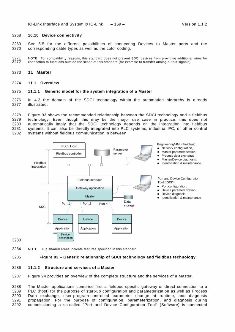
IO-Link Interface and System © IO-Link – 169 – Version 1.1.2
10.10 Device connectivity 3268
See 5.5 for the different possibilities of connecting Devices to Master ports and the 3269 corresponding cable types as well as the color coding. 3270
NOTE For compatibility reasons, this standard does not prevent SDCI devices from providing additional wires for 3271 connection to functions outside the scope of this standard (for example to transfer analog output signals). 3272
11 Master 3273
11.1 Overview 3274
11.1.1 Generic model for the system integration of a Master 3275
In 4.2 the domain of the SDCI technology within the automation hierarchy is already 3276 illustrated. 3277
Figure 93 shows the recommended relationship between the SDCI technology and a fieldbus 3278 technology. Even though this may be the major use case in practice, this does not 3279 automatically imply that the SDCI technology depends on the integration into fieldbus 3280 systems. It can also be directly integrated into PLC systems, industrial PC, or other control 3281 systems without fieldbus communication in between. 3282
Device
Application
Device
Application
Device
Application
Fieldbus interface
Data storage
Parameter server
SDCI
PLC / Host
Fieldbusintegration
Device description
Port 2
Engineering/HMI (Fieldbus): Network configuration, Master parameterization, Process data exchange Master/Device diagnosis, Identification & maintenance
Port 1 Port n
Fieldbus controller
Gateway application
Master
Port configuration, Device parameterization, Device diagnosis, Identification & maintenance
Port and Device Configuration Tool (IODD):
3283
NOTE Blue shaded areas indicate features specified in this standard 3284
Figure 93 – Generic relationship of SDCI technology and fieldbus technology 3285
11.1.2 Structure and services of a Master 3286
Figure 94 provides an overview of the complete structure and the services of a Master. 3287
The Master applications comprise first a fieldbus specific gateway or direct connection to a 3288 PLC (host) for the purpose of start-up configuration and parameterization as well as Process 3289 Data exchange, user-program-controlled parameter change at runtime, and diagnosis 3290 propagation. For the purpose of configuration, parameterization, and diagnosis during 3291 commissioning a so-called "Port and Device Configuration Tool" (Software) is connected 3292

Version 1.1.2 – 170 – IO-Link Interface and System © IO-Link
either directly to the Master or via fieldbus communication. These two instruments are using 3293 the following common Master applications 3294
• Configuration Manager (CM), which transforms the user configuration assignments into 3295 port set-ups; 3296
• On-request Data Exchange (ODE), which provides for example acyclic parameter access; 3297
• Data Storage (DS) mechanism, which can be used to save and restore the Device 3298 parameters; 3299
• Diagnosis Unit (DU), which routes Events from the AL to the Data Storage unit or the 3300 gateway application; 3301
• Process Data Exchange (PDE), building the bridge to upper level automation instruments. 3302
These Master applications provide standard methods/functions common to all Masters. 3303
The Configuration Manager (CM) and the Data Storage mechanism (DS) need special 3304 coordination in respect to On-request Data, see Figure 95 and Figure 105. 3305
The gateway application maps these functions into the features of a particular fieldbus/PLC or 3306 directly into a host system. It is not within the scope of this standard to define any of these 3307 gateway applications. 3308
MasterDL-modehandler
MessagehandlerSystem
management
On-request Datahandler
Process Datahandler
DL-B
DL-A
PL_Transfer.req PL_Transfer.ind
PD
.req
PD
Trig
DL_
Eve
nt
DL_
PD
Out
-pu
tUpd
ate
DL_
PD
Inpu
t -Tr
ansp
ort
DL_
Rea
d -P
aram
DL_
Writ
e-P
aram
DL_
ISD
U-
Tran
spor
t
DL_
Con
trol
DL_
PD
Cyc
le
PL_WakeUp.req
Coordi-nation
SM
_Set
Por
tCon
fig
SM
_Por
tMod
e
SM
_Get
Por
tCon
fig
SM
_Ope
rate
Application Layer
PL_SetMode.req
OD
.req
OD
.cnf
Eve
ntFl
ag
Wake-up Switching signalCoded switchingInactive
Data Link Layer
Mode switch
Physical layer (port)
SIO:DI / DO
DL_SetMode
DL_Read
DL_Write
DL_Mode
Process Dataobjects
On-request Dataobjects AL
AL_
Rea
d
AL_
Writ
e
AL_
Abo
rt
AL_
Con
trol
AL_
Eve
nt
AL_
Get
Inpu
t
AL_
New
Inpu
t
AL_
Set
Out
put
AL_
PD
Cyc
le
SIO:DI / DO
Port xHandler
Data Storage
Master applications
Process Data Exchange
Gateway application (configuration, parameterization, diagnosis, on-request, and process data)
Configuration Manager Diagnosis Unit
MHInfo
DL_
ISD
U-
Abo
rt
DL_
Eve
nt-
Con
fAL_Read
On-request Data Exchange
PD
.cnf
PD
InS
tatu
s
OD
Trig
3309
Figure 94 – Structure and services of a Master 3310
Figure 95 shows the relationship of the common Master applications. 3311

IO-Link Interface and System © IO-Link – 171 – Version 1.1.2
Gateway application (configuration, parameterization, diagnosis, on-request, and process data)Gateway application (configuration, parameterization, diagnosis, on-request, and process data)
ConfigurationManagment
(CM)
ConfigurationManagment
(CM)
Data Storage
(DS)
Data Storage
(DS)
On-requestData
Exchange(ODE)
On-requestData
Exchange(ODE)
DS_Startup
DS_Ready
DS_Fault
Start of portand Device
Data Storageinterface
On-request Datainterface
Diagnosisinterface
Process Datainterface
Ope
ratin
gMod
e
Ope
ratin
g or
Fau
lt
DS
_Del
ete
OD_Block
OD_Unblock DiagnosisUnit(DU)
DiagnosisUnit(DU)
ProcessData
Exchange(PDE)
ProcessData
Exchange(PDE)
DU
_Sta
rt
Eve
nts
PD
_Sta
rt
DS_Upload
AL_Write AL_Read AL_Write AL_Control
AL_Event(response)
AL_Event(Indication)
AL PD servicesAL_ReadSM services
OD
_Sto
p
OD
_Sta
rt
Dat
a
Dat
a
DU
_Sto
p
PD
_Sto
p
Dat
a
Rea
dyTo
Ope
rate
Sta
rtOpe
rate
3312
Figure 95 – Relationship of the common Master applications 3313
The internal variables between the common Master applications are specified in Table 100. 3314 The main responsibility is assigned to the Configuration Manager (CM) as shown in Figure 95 3315 and explained in 11.2. 3316
Table 100 – Internal variables and Events to control the common Master applications 3317
Internal Variable Definition
OperatingMode This variable activates the port and provides the configuration parameters.
ReadyToOperate This variable indicates correct configuration of the port.
StartOperate This variable allows for explicite change of all ports to the OPERATE mode.
Operating This variable indicates all ports are in cyclic Process Data exchange mode
Fault This variable indicates abandoned COMx communication at any port (see Figure 98 and Table 101).
DS_Startup This variable triggers the Data Storage (DS) state machine causing an Upload or Download of Device parameters if required (see 11.3).
DS_Ready This variable indicates the Data Storage has been accomplished successfully; operating mode is CFGCOM or AUTOCOM (see 9.2.2.2)
DS_Fault This variable indicates the Data Storage has been aborted due to a fault.
DS_Delete Any verified change of Device configuration leads to a deletion of the stored data set in the Data Storage.
DS_Upload This variable triggers the Data Storage state machine in the Master due to the special Event "DS_UPLOAD_REQ" from the Device.
OD_Start This variable enables On-request Data access via AL_Read and AL_Write.
OD_Stop This variable indicates that On-request Data access via AL_Read and AL_Write is acknowledged with a negative response to the gateway application.
OD_Block Data Storage upload and download actions disable the On-request Data access through AL_Read or AL_Write. Access by the gateway application is denied.
OD_Unblock This variable enables On-request Data access via AL_Read or AL_Write.
DU_Start This variable enables the Diagnosis Unit to propagate remote (Device) or local (Master) Events to the gateway application.
DU_Stop This variable indicates that the Device Events are not propagated to the gateway application and not acknowledged. Available Events are blocked until the DU is enabled again.
PD_Start This variable enables the Process Data exchange with the gateway application.
PD_Stop This variable disables the Process Data exchange with the gateway application.
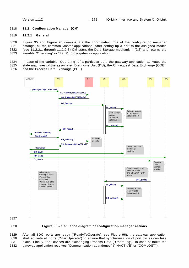
Version 1.1.2 – 172 – IO-Link Interface and System © IO-Link
11.2 Configuration Manager (CM) 3318
11.2.1 General 3319
Figure 95 and Figure 96 demonstrate the coordinating role of the configuration manager 3320 amongst all the common Master applications. After setting up a port to the assigned modes 3321 (see 11.2.2.1 through 11.2.2.3) CM starts the Data Storage mechanism (DS) and returns the 3322 variable "Operating" or "Fault" to the gateway application. 3323
In case of the variable "Operating" of a particular port, the gateway application activates the 3324 state machines of the associated Diagnosis Unit (DU), the On-request Data Exchange (ODE), 3325 and the Process Data Exchange (PDE). 3326
CM SM
SM_PortMode(COMREADY)
SM_SetPortConfig(CFGCOM)
SM_Operate()
SM_PortMode(SM_OPERATE)
SM_PortMode(COMREADY)
SM_SetPortConfig(CFGCOM)
SM_Operate()
SM_PortMode(SM_OPERATE)
DS
DS_Startup()
DS_Ready()
DS_Startup()
DS_Ready()
OD_Unblock()
ODE
OD_Unblock()
OD_Block()
OD_Unblock()
OD_Block()
OD_Block()
OD_Unblock()
OD_Block()
DU
DS_Upload()DS_Upload()
OD_Start()
Gateway
OperatingMode(FIXEDMODE)
DU_Start()
Operating()
ReadyToOperate()
StartOperate()
OD_Start()
OperatingMode(FIXEDMODE)
DU_Start()
Operating()
ReadyToOperate()
StartOperate()
PD_Start()
PDE
PD_Start()
Data Storage active:Download, upload, none
Gateway access to On-request Data disabled
On-request Data Exchange enabled
Processing of events enabled. Event "DS_UPLOAD_REQ" occurs
Gateway access to On-request Data disabled
All ports are working in cyclic Process Data exchange.Device available for example to a fieldbus system
Process Data Exchange enabled
Activatesall ports
3327
Figure 96 – Sequence diagram of configuration manager actions 3328
After all SDCI ports are ready ("ReadyToOperate", see Figure 96), the gateway application 3329 shall activate all ports ("StartOperate") to ensure that synchronization of port cycles can take 3330 place. Finally, the Devices are exchanging Process Data ("Operating"). In case of faults the 3331 gateway application receives "Communication abandoned" ("INACTIVE" or "COMLOST"). 3332

IO-Link Interface and System © IO-Link – 173 – Version 1.1.2
In case of SM_PortMode (COMP_FAULT, REVISION_FAULT, or SERNUM_FAULT) according 3333 to 9.2.3, only the ODE machine shall be activated to allow for parameterization. 3334
At each new start of a port the gateway application will first de-activate (e.g. OD_Stop) the 3335 associated machines DU, ODE, and PDE. 3336
Several parameters are available for the configuration manager to achieve a specific 3337 behaviour. 3338
11.2.2 Configuration parameter 3339
11.2.2.1 OperatingMode 3340
One of the following operating modes can be selected. All modes are mandatory. 3341
INACTIVE 3342 The SDCI port is deactivated, the corresponding Process Data length for input and output is 3343 zero. The Master shall not have any activities on this port. 3344
DO 3345 The SDCI port is configurated as a digital output (see Table 2 for constraints). The output 3346 Process Data length is 1 bit. The Master shall not try to wake up any Device at this port. 3347
DI 3348 The SDCI port is configurated as a digital input. The input Process Data length is 1 bit. The 3349 Master shall not try to wake up any Device at this port. 3350
FIXEDMODE 3351 An SDCI port is configured for continuous communication. The defined identification is 3352 checked. Whether a difference in Device identification will lead to the rejection of the Device 3353 or not depends on the port configuration (InspectionLevel, see Table 78). 3354
SCANMODE 3355 The SDCI port is configured for continuous communication. The identification is read back 3356 from the Device and can be provided as the new defined identification. Otherwise see 3357 OperatingMode "FIXEDMODE". 3358
11.2.2.2 PortCycle 3359
One of the following port cycle modes can be selected. None of the modes is mandatory. 3360
FreeRunning 3361 The port cycle timing is not restricted. 3362
FixedValue 3363 The port cycle timing is fixed to a specific value. If the Device is not able to achieve this ti-3364 ming, for example if the timing is lower than the MinCycleTime of the Device, an error shall be 3365 generated. The fixed value can be written in the CycleTime parameter as specified in 3366 11.2.2.3. 3367
MessageSync 3368
The port cycle timing is restricted to the synchronous start of all messages on all SDCI ports 3369 of this Master. In this case the cycle time is given by the highest MinCycleTime of the 3370 connected Devices. All Master ports set to this mode are working with this behaviour as 3371 shown in Figure 97. Values for displacement and jitter shall be noted in the user manual. 3372

Version 1.1.2 – 174 – IO-Link Interface and System © IO-Link
t
Port 1
Port 2
Port 3
Port 4
CycleTime 3373
Figure 97 – Ports in MessageSync mode 3374
11.2.2.3 CycleTime 3375
This parameter contains the requested or actual cycle time for the specific ports. It shall be 3376 passed as a value with a resolution of 100 µs. 3377
11.2.2.4 PDConfig 3378
This set of parameters contains the rules for the Process Data mapping between the Device 3379 Process Data stream and the gateway Process Data stream (see example in Figure 107 for 3380 the definitions). 3381
LenIn 3382 This parameter contains the requested length of the Device input ProcessDataIn Bits 3383
PosIn 3384 This parameter contains the offset within the gateway input Process Data stream in Bit. 3385
SrcOffsetIn 3386 This parameter contains the offset within the Device input Process Data stream in Bit. 3387
LenOut 3388 This parameter contains the requested length of the Device output ProcessDataOut Bits. 3389
PosOut 3390 This parameter contains the offset within the gateway output Process Data stream in Bit. 3391
SrcOffsetOut 3392 This parameter contains the offset within the Device output Process Data stream in Bit. 3393
11.2.2.5 DeviceIdentification 3394
This set of parameters contains the actual configured Device identification. 3395
VendorID 3396 This parameter contains the requested or read vendor specific ID as specified in B.1.8. 3397
DeviceID 3398 This parameter contains the requested or read Device specific ID as specified in B.1.9. 3399
SerialNumber 3400
This parameter contains the requested or read SerialNumber as specified in B.2.13. 3401
InspectionLevel 3402
This parameter contains the requested InspectionLevel as specified in Table 78. 3403
11.2.2.6 DataStorageConfig 3404
This set of parameter items contains the settings of the Data Storage (DS) mechanism. 3405

IO-Link Interface and System © IO-Link – 175 – Version 1.1.2
ActivationState 3406 This parameter contains the requested state of the DS mechanism for this port. The following 3407 modes are supported: 3408
DS_Enabled 3409 The DS mechanism is active and provides the full functionality as specified in 11.3.2. 3410
DS_Disabled 3411 The DS mechanism is inactive and the complete parameter set of this port remains stored. 3412
DS_Cleared 3413 The DS mechanism is disabled and the stored parameter set of this port is cleared. 3414
DownloadEnable 3415 The DS mechanism is permitted to write data to the connected Device. 3416
UploadEnable 3417 The DS mechanism is permitted to read data from the connected Device. 3418
11.2.3 State machine of the Configuration Manager 3419
Figure 98 shows the state machine of the Master configuration manager. 3420
Inactive_0
/Initialization
[AUTOCOM]/T2
SM_Startup_1
[CFGCOM]/T1
[AUTOCOM]/T2
[CFGCOM]/T1
SM_PortMode_COMREADY/T3
DS_ParamManager_2
SM_PortMode_COMREADY/T3
WaitingOnOperate_5
Port_Active_6
SM_PortMode_OPERATE/T8SM_PortMode_OPERATE/T8
SM_PortMode_yMODE/T9SM_PortMode_yMODE/T9
SM_PortMode_xFAULT/T4
PortFault_3 SM_PortMode_xFAULT/T4
[DS_Fault]/T6[DS_Fault]/T6
Port_DIDO_7[DO]/T11
[DI]/T10
[Inactive]/T12
[DO]/T11
[DI]/T10
[Inactive]/T12
CM_ReadyToOperate_4
[DS_Ready]/T5
[StartOperate]/T7
[DS_Ready]/T5
[StartOperate]/T7
3421
Key: 3422 xFAULT: REV_FAULT or COMP_FAULT or SERNUM_FAULT 3423 yMODE: INACTIVE or COMLOST 3424
Figure 98 – State machine of the Configuration Manager 3425

Version 1.1.2 – 176 – IO-Link Interface and System © IO-Link
The different states show the steps of necessary commands to establish or maintain 3426 communication or the DI or DO state. 3427
Any change of the port configuration can be activated by changing the OperatingMode 3428 variable (see 11.2.2.1). 3429
Table 101 shows the state transition table of the configuration manager state machine. 3430
Table 101 – State transition tables of the Configuration Manager 3431
STATE NAME STATE DESCRIPTION
Inactive_0 Waiting on any of the OperatingMode variables from the gateway application: DO, DI, AUTOCOM, or CFGCOM.
SM_Startup_1 Waiting on an established communication or loss of communication or any of the faults REVISION_FAULT, COMP_FAULT, or SERNUM_FAULT (see Table 83).
DS_ParamManager_2 Waiting on accomplished Data Storage startup. Parameter are downloaded into the Device or uploaded from the Device.
PortFault_3 Device in state PREOPERATE (communicating). However, one of the three faults REVISION_FAULT, COMP_FAULT, SERNUM_FAULT, or DS_Fault occurred.
CM_ReadytoOperate_4 Port is waiting until the gateway application indicates "StartOperate".
WaitingOnOperate_5 Waiting on SM to switch to OPERATE.
PortActive_6 Port is in OPERATE mode. The gateway application is exchanging Process Data and ready to send or receive On-request Data.
PortDIDO_7 Port is in DI or DO mode. The gateway application is exchanging Process Data (DI or DO).
3432 TRANSITION SOURCE
STATE TARGET STATE
ACTION
T1 0 1 SM_SetPortConfig_CFGCOM
T2 0 1 SM_SetPortConfig_AUTOCOM
T3 1 2 DS_Startup: The DS state machine is triggered.
T4 1 3 "Fault" indication to gateway application (REVISION_FAULT, COMP_FAULT, or SERNUM_FAULT), see Figure 95.
T5 2 4 Indication to gateway application: ReadyToOperate
T6 2 3 Data Storage failed. Rollback to previous parameter set.
T7 4 5 SM_Operate.
T8 5 6 Indication to gateway application: "Operating" (see Figure 96).
T9 1,2,3,4,5,6
0 SM_SetPortConfig_INACTIVE. "Fault" indication to gateway application: COMLOST or INACTIVE
T10 0 7 SM_SetPortConfig_DI. Indication to gateway application: DI
T11 0 7 SM_SetPortConfig_DO. Indication to gateway application: DO
T12 7 0 SM_SetPortConfig_INACTIVE. 3433
INTERNAL ITEMS TYPE DEFINITION
DS_Ready Bool Data Storage sequence (upload, download) accomplished. Port operating mode is FIXEDMODE or SCANMODE. See Table 100.
DS_Fault Bool See Table 100.
StartOperate Bool Gateway application causes the port to switch to OPERATE.
FIXEDMODE Bool One of the OperatingModes (see 11.2.2.1)
SCANMODE Bool One of the OperatingModes (see 11.2.2.1)
DI Bool One of the OperatingModes (see 11.2.2.1)
DO Bool One of the OperatingModes (see 11.2.2.1)

IO-Link Interface and System © IO-Link – 177 – Version 1.1.2
11.3 Data Storage (DS) 3434
11.3.1 Overview 3435
Data Storage between Master and Device is specified within this standard, whereas the 3436 adjacent upper Data Storage mechanisms depend on the individual fieldbus or system. The 3437 Device holds a standardized set of objects providing parameters for Data Storage, memory 3438 size requirements, control and state information of the Data Storage mechanism. Changes of 3439 Data Storage parameter sets are detectable via the "Parameter Checksum" (see 10.4.8). 3440
11.3.2 DS data object 3441
The structure of a Data Storage data object is specified in Table F.1. 3442
The Master shall always hold the header information (Parameter Checksum, VendorID, and 3443 DeviceID) for the purpose of checking and control. The object information (objects 1…n) will 3444 be stored within the non-volatile memory part of the Master (see Annex F). Prior to a 3445 download of the Data Storage data object (parameter block), the Master will check the 3446 consistency of the header information with the particular Device. 3447
The maximum permitted size of the Data Storage data object is 2 x 210 octets. It is mandatory 3448 for Masters to provide at least this memory space per port if the Data Storage mechanism is 3449 implemented. 3450
11.3.3 DS state machine 3451
The Data Storage mechanism is called right after establishing the COMx communication, 3452 before entering the OPERATE mode. During this time any other communication with the 3453 Device shall be rejected by the gateway. 3454
Figure 99 shows the state machine of the Data Storage mechanism. 3455
/Initialization
CheckActivationState_0 [DS_Cleared or DS_Disabled]/T7
Off_3
DS_Upload/T13
DS_Delete/T10
DS_Startup/T14
[DS_Cleared or DS_Disabled]/T7 DS_Upload/T13
DS_Delete/T10
DS_Startup/T14
UpDownload_2
enex_2enex_1
[DS_Enabled & COMx]/T6[DS_Enabled & COMx]/T6
WaitingOnDSActivity_1DS_Upload/T4
[DS_Ready]/T3
DS_Disabled/T12
DS_Cleared/T11
[DS_Enabled]/T1
DS_Startup/T2
[DS_Enabled & NoCOMx]/T8
[DS_Delete]/T9
[DS_Fault]/T5
DS_Upload/T4
[DS_Ready]/T3
DS_Disabled/T12
DS_Cleared/T11
[DS_Enabled]/T1
DS_Startup/T2
[DS_Enabled & NoCOMx]/T8
[DS_Delete]/T9
[DS_Fault]/T5
3456
Figure 99 – Main state machine of the Data Storage mechanism 3457
Figure 100 shows the submachine of the state "UpDownload_2". 3458

Version 1.1.2 – 178 – IO-Link Interface and System © IO-Link
This submachine can be invoked by the Data Storage mechanism or during runtime triggered 3459 by a "DS_UPLOAD_REQ" Event. 3460
UpDownload_2
CheckIdentity_4
CheckMemSize_5
[Passed]/T16
CheckUpload_6
[Passed]/T18
CheckDSValidity_8
[No Upload requested]/T20
CheckChecksum_9
[DS_Valid]/T22
Download_10
enex_6enex_5
[Checksum_Mismatch &DownloadEnable]/T24
Upload_7
enex_4
enex_3
[DS_UPLOAD_Flag & UploadEnable]/T19
[DS_Invalid & UploadEnable]/T21
DS_Fault_12
[Not passed]/T15
[Not passed]/T17
[Upload failed]/T23
[Download failed]/T28
[Data Storage locked]/T29
DS_Ready_11[Checksum_Match]/T25
[Upload done]/T26
[Download done]/T27enex_2enex_1
[Passed]/T16
[Passed]/T18
[No Upload requested]/T20
[DS_Valid]/T22
[Checksum_Mismatch &DownloadEnable]/T24
[DS_UPLOAD_Flag & UploadEnable]/T19
[DS_Invalid & UploadEnable]/T21
[Not passed]/T15
[Not passed]/T17
[Upload failed]/T23
[Download failed]/T28
[Data Storage locked]/T29
[Checksum_Match]/T25
[Upload done]/T26
[Download done]/T27
[DS_Ready][DS_Fault]
3461
Figure 100 – Submachine "UpDownload_2" of the Data Storage mechanism 3462
Figure 101 shows the submachine of the state "Upload_7". 3463
This state machine can be invoked by the Data Storage mechanism or during runtime 3464 triggered by a DS_UPLOAD_REQ Event. 3465
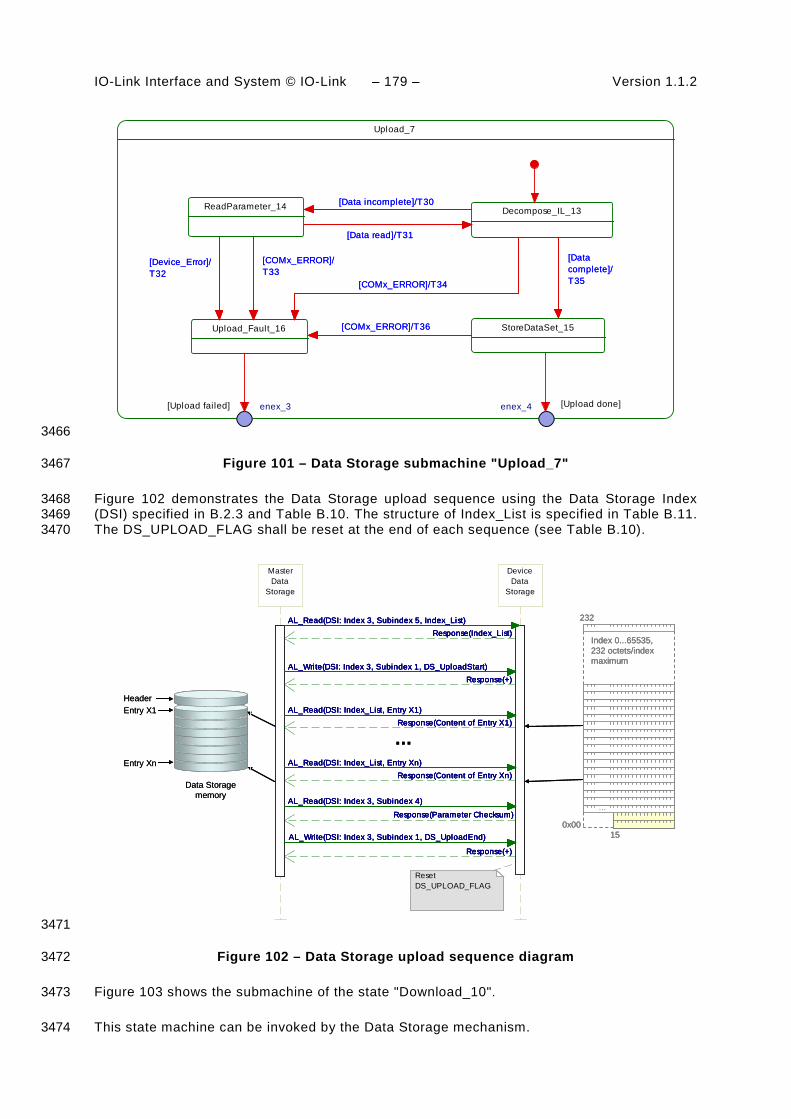
IO-Link Interface and System © IO-Link – 179 – Version 1.1.2
Upload_7
Decompose_IL_13ReadParameter_14 [Data incomplete]/T30
[Data read]/T31
StoreDataSet_15
[Data complete]/T35
Upload_Fault_16 [COMx_ERROR]/T36
[COMx_ERROR]/T33
[Device_Error]/T32
[COMx_ERROR]/T34
enex_4enex_3
[Data incomplete]/T30
[Data read]/T31
[Data complete]/T35
[COMx_ERROR]/T36
[COMx_ERROR]/T33
[Device_Error]/T32
[COMx_ERROR]/T34
[Upload done][Upload failed]
3466
Figure 101 – Data Storage submachine "Upload_7" 3467
Figure 102 demonstrates the Data Storage upload sequence using the Data Storage Index 3468 (DSI) specified in B.2.3 and Table B.10. The structure of Index_List is specified in Table B.11. 3469 The DS_UPLOAD_FLAG shall be reset at the end of each sequence (see Table B.10). 3470
Data Storagememory
Entry X1
Entry Xn
Header
232
Index 0...65535,232 octets/indexmaximum
...
0x0015
MasterData
Storage
AL_Write(DSI: Index 3, Subindex 1, DS_UploadStart)
DeviceData
Storage
AL_Write(DSI: Index 3, Subindex 1, DS_UploadStart)Response(+)
AL_Read(DSI: Index_List, Entry X1)Response(Content of Entry X1)
AL_Read(DSI: Index_List, Entry Xn)Response(Content of Entry Xn)
AL_Write(DSI: Index 3, Subindex 1, DS_UploadEnd)
Response(+)
Response(Index_List)AL_Read(DSI: Index 3, Subindex 5, Index_List)
AL_Read(DSI: Index 3, Subindex 4)
Response(Parameter Checksum)
Response(+)
AL_Read(DSI: Index_List, Entry X1)Response(Content of Entry X1)
AL_Read(DSI: Index_List, Entry Xn)Response(Content of Entry Xn)
AL_Write(DSI: Index 3, Subindex 1, DS_UploadEnd)
Response(+)
Response(Index_List)AL_Read(DSI: Index 3, Subindex 5, Index_List)
AL_Read(DSI: Index 3, Subindex 4)
Response(Parameter Checksum)
...
Reset DS_UPLOAD_FLAG
Data Storagememory
Entry X1
Entry Xn
Header
232
Index 0...65535,232 octets/indexmaximum
...
0x0015
232
Index 0...65535,232 octets/indexmaximum
...
0x0015
MasterData
Storage
AL_Write(DSI: Index 3, Subindex 1, DS_UploadStart)
DeviceData
Storage
AL_Write(DSI: Index 3, Subindex 1, DS_UploadStart)Response(+)
AL_Read(DSI: Index_List, Entry X1)Response(Content of Entry X1)
AL_Read(DSI: Index_List, Entry Xn)Response(Content of Entry Xn)
AL_Write(DSI: Index 3, Subindex 1, DS_UploadEnd)
Response(+)
Response(Index_List)AL_Read(DSI: Index 3, Subindex 5, Index_List)
AL_Read(DSI: Index 3, Subindex 4)
Response(Parameter Checksum)
Response(+)
AL_Read(DSI: Index_List, Entry X1)Response(Content of Entry X1)
AL_Read(DSI: Index_List, Entry Xn)Response(Content of Entry Xn)
AL_Write(DSI: Index 3, Subindex 1, DS_UploadEnd)
Response(+)
Response(Index_List)AL_Read(DSI: Index 3, Subindex 5, Index_List)
AL_Read(DSI: Index 3, Subindex 4)
Response(Parameter Checksum)
...
Reset DS_UPLOAD_FLAG
3471
Figure 102 – Data Storage upload sequence diagram 3472
Figure 103 shows the submachine of the state "Download_10". 3473
This state machine can be invoked by the Data Storage mechanism. 3474
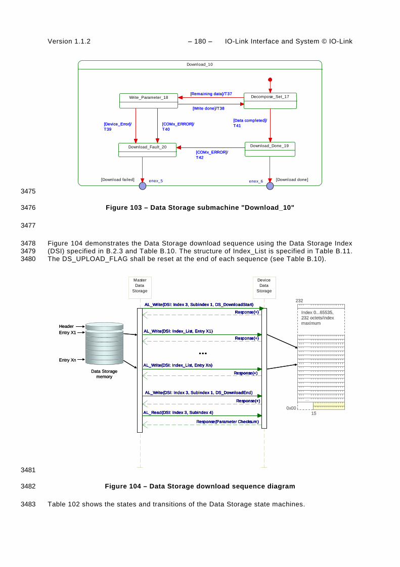
Version 1.1.2 – 180 – IO-Link Interface and System © IO-Link
Download_10
Decompose_Set_17Write_Parameter_18[Remaining data]/T37
[Write done]/T38
Download_Done_19
[Data completed]/T41
Download_Fault_20[COMx_ERROR]/T42
[COMx_ERROR]/T40
[Device_Error]/T39
enex_6enex_5
[Remaining data]/T37
[Write done]/T38
[Data completed]/T41
[COMx_ERROR]/T42
[COMx_ERROR]/T40
[Device_Error]/T39
[Download failed] [Download done]
3475
Figure 103 – Data Storage submachine "Download_10" 3476
3477
Figure 104 demonstrates the Data Storage download sequence using the Data Storage Index 3478 (DSI) specified in B.2.3 and Table B.10. The structure of Index_List is specified in Table B.11. 3479 The DS_UPLOAD_FLAG shall be reset at the end of each sequence (see Table B.10). 3480
Data Storagememory
Entry X1
Entry Xn
Header
232
Index 0...65535,232 octets/indexmaximum
...
0x0015
MasterData
Storage
AL_Write(DSI: Index_List, Entry X1)
DeviceData
Storage
AL_Write(DSI: Index_List, Entry X1)
Response(+)
AL_Write(DSI: Index_List, Entry Xn)
Response(+)
AL_Write(DSI: Index 3, Subindex 1, DS_DownloadEnd)
Response(+)
Response(+)
AL_Write(DSI: Index 3, Subindex 1, DS_DownloadStart)
AL_Read(DSI: Index 3, Subindex 4)
Response(Parameter Checksum)
Response(+)
AL_Write(DSI: Index_List, Entry Xn)
Response(+)
AL_Write(DSI: Index 3, Subindex 1, DS_DownloadEnd)
Response(+)
Response(+)
AL_Write(DSI: Index 3, Subindex 1, DS_DownloadStart)
AL_Read(DSI: Index 3, Subindex 4)
Response(Parameter Checksum)
...
Data Storagememory
Entry X1
Entry Xn
Header
232
Index 0...65535,232 octets/indexmaximum
...
0x0015
232
Index 0...65535,232 octets/indexmaximum
...
0x0015
MasterData
Storage
AL_Write(DSI: Index_List, Entry X1)
DeviceData
Storage
AL_Write(DSI: Index_List, Entry X1)
Response(+)
AL_Write(DSI: Index_List, Entry Xn)
Response(+)
AL_Write(DSI: Index 3, Subindex 1, DS_DownloadEnd)
Response(+)
Response(+)
AL_Write(DSI: Index 3, Subindex 1, DS_DownloadStart)
AL_Read(DSI: Index 3, Subindex 4)
Response(Parameter Checksum)
Response(+)
AL_Write(DSI: Index_List, Entry Xn)
Response(+)
AL_Write(DSI: Index 3, Subindex 1, DS_DownloadEnd)
Response(+)
Response(+)
AL_Write(DSI: Index 3, Subindex 1, DS_DownloadStart)
AL_Read(DSI: Index 3, Subindex 4)
Response(Parameter Checksum)
...
3481
Figure 104 – Data Storage download sequence diagram 3482
Table 102 shows the states and transitions of the Data Storage state machines. 3483

IO-Link Interface and System © IO-Link – 181 – Version 1.1.2
Table 102 – States and transitions of the Data Storage state machines 3484
STATE NAME STATE DESCRIPTION
CheckActivationState_0 Check current state of the DS configuration: Independently from communication status, DS_Startup from configuration management or an Event DS_UPLOAD_REQ is expected.
WaitingOnDSActivity_1 Waiting for upload request, Device startup, all changes of activation state independent of the Device communication state.
UpDownload_2 Submachine for up/download actions and checks
Off_3 Data Storage handling switched off or deactivated
SM: CheckIdentity_4 Check Device identification (DeviceID, VendorID) against parameter set within the Data Storage (see Table F.2). Empty content does not lead to a fault.
SM: CheckMemSize_5 Check data set size (Index 3, Subindex 3) against available Master storage size
SM: CheckUpload_6 Check for DS_UPLOAD_FLAG within the Data Storage Index (see Table B.10)
SM: Upload_7 Submachine for the upload actions
SM: CheckDSValidity_8 Check whether stored data within the Master is valid or invalid. A Master could be replaced between upload and download activities. It is the responsibility of a Master designer to implement a validity mechanism according to the chosen use cases
SM: CheckChecksum_9 Check for differences between the data set content and the Device parameter via the "Parameter Checksum" within the Data Storage Index (see Table B.10)
SM: Download_10 Submachine for the download actions
SM: DS_Ready_11 Prepare DS_Ready indication to the Configuration Management (CM)
SM: DS_Fault_12 Prepare DS_Fault indication from "Identification_Fault", "SizeCheck_Fault", "Upload_Fault", and "Download_Fault" to the Configuration Management (CM)
SM: Decompose_IL_13 Read Index List within the Data Storage Index (see Table B.10). Read content entry by entry of the Index List from the Device (see Table B.11).
SM: ReadParameter_14 Wait until read content of one entry of the Index List from the Device is accomplished.
SM: StoreDataSet_15 Task of the gateway application: store entire data set according to Table F.1 and Table F.2
SM: Upload_Fault_16 Prepare Upload_Fault indication from "Device_Error" and "COM_ERROR" as input for the higher level indication DS_Fault.
SM: Decompose_Set_17 Write parameter by parameter of the data set into the Device according to Table F.1.
SM: Write_Parameter_18 Wait until write of one parameter of the data set into the Device is accomplished.
SM: Download_Done_19 Download completed. Read back "Parameter Checksum" from the Data Storage Index according to Table B.10. Save this value in the stored data set according to Table F.2.
SM: Download_Fault_20 Prepare Download_Fault indication from "Device_Error" and "COM_ERROR" as input for the higher level indication DS_Fault.
3485 TRANSITION SOURCE
STATE TARGET STATE
ACTION
T1 0 1 -
T2 1 2 -
T3 2 1 OD_Unblock; Indicate DS_Ready to CM
T4 1 2 Confirm Event "DS_UPLOAD_REQ"
T5 2 1 DS_Break (AL_Write, Index 3, Subindex 1); clear intermediate data (garbage collection); rollback to previous parameter state; DS_Fault (see Figure 95); OD_Unblock.
T6 3 2 -
T7 0 3 -
T8 3 1 -
T9 1 1 Clear saved parameter set (see Table F.1 and Table F.2)
T10 3 3 Clear saved parameter set (see Table F.1 and Table F.2)

Version 1.1.2 – 182 – IO-Link Interface and System © IO-Link
TRANSITION SOURCE STATE
TARGET STATE
ACTION
T11 1 3 Clear saved parameter set (see Table F.1 and Table F.2)
T12 1 3 -
T13 3 3 Confirm Event "DS_UPLOAD_REQ"; no further action
T14 3 3 DS_Ready to CM
T15 4 12 Indicate DS_Fault(Identification_Fault) to the gateway application
T16 4 5 Read "Data Storage Size" according to Table B.10, OD_Block
T17 5 12 Indicate DS_Fault(SizeCheck_Fault) to the gateway application
T18 5 6 Read "DS_UPLOAD_FLAG" according to Table B.10
T19 6 7 Data Storage Index 3, Subindex 1: "DS_UploadStart" (see Table B.10)
T20 6 8 -
T21 8 7 Data Storage Index 3, Subindex 1: "DS_UploadStart" (see Table B.10)
T22 8 9 -
T23 7 12 Data Storage Index 3, Subindex 1: "DS_Break" (see Table B.10). Indicate "DS_Fault(Upload)" to the gateway application
T24 9 10 Data Storage Index 3, Subindex 1: "DS_DownloadStart" (see Table B.10)
T25 9 11 -
T26 7 11 Data Storage Index 3, Subindex 1: "DS_UploadEnd"; read Parameter Checksum (see Table B.10)
T27 10 11 -
T28 10 12 Data Storage Index 3, Subindex 1: "DS_Break" (see Table B.10). Indicate "DS_Fault(Download)" to the gateway application.
T29 6 12 Indicate DS_Fault(Data Storage locked) to the gateway application
T30 13 14 AL_Read (Index List)
T31 14 13 -
T32 14 16 -
T33 14 16 -
T34 13 16 -
T35 13 15 Read "Parameter Checksum" (see Table B.10).
T36 15 16 -
T37 17 18 Write parameter via AL_Write
T38 18 17 -
T39 18 20 -
T40 18 20 -
T41 17 19 Data Storage Index 3, Subindex 1: "DS_DownloadEnd" (see Table B.10) Read "Parameter Checksum" (see Table B.10).
T42 19 20 - 3486
INTERNAL ITEMS TYPE DEFINITION
DS_Cleared Bool Data Storage handling switched off, see 11.2.2.6
DS_Disabled Bool Data Storage handling deactivated, see 11.2.2.6
DS_Enabled Bool Data Storage handling activated, see 11.2.2.6
COMx_ERROR Bool Error in COMx communication detected
Device_Error Bool Access to Index denied, AL_Read or AL_Write.cnf(-) with ErrorCode 0x80
DS_Startup Variable Trigger from CM state machine, see Figure 95
NoCOMx Bool No COMx communication

IO-Link Interface and System © IO-Link – 183 – Version 1.1.2
INTERNAL ITEMS TYPE DEFINITION
COMx Bool COMx communication working properly
DS_UPLOAD_REQ Event See Table D.2
UploadEnable Bool Data Storage handling configuration, see 11.2.2.6
DownloadEnable Bool Data Storage handling configuration, see 11.2.2.6
DS_Valid Bool Valid parameter set available within the Master. See state description "SM: CheckDSValidity_8"
DS_Invalid Bool No valid parameter set available within the Master. See state description "SM: CheckDSValidity_8"
Checksum_Mismatch Bool Acquired "Parameter Checksum" from Device does not match the checksum within Data Storage (binary comparison)
Checksum_Match Bool Acquired "Parameter Checksum" from Devive matches the checksum within Data Storage (binary comparison)
3487 11.3.4 Parameter selection for Data Storage 3488
The Device designer defines the parameters that are part of the Data Storage mechanism. 3489
The IODD marks all parameters not included in Data Storage with the attribute 3490 "excludedFromDataStorage". However, the Data Storage mechanism shall not consider the 3491 information from the IODD but rather the Parameter List read out from the Device. 3492
11.4 On-Request Data exchange (ODE) 3493
Figure 105 shows the state machine of the Master's On-request Data Exchange. This 3494 behaviour is mandatory for a Master. 3495
During an active data transmission of the Data Storage mechanism, all On-request Data 3496 requests are blocked. 3497
Inactive_0
[ODrequest]/T1
ODactive_1
OD_Start/T2
OD_Stop/T3
[ODrequest]/T4
ODblocked_2OD_Block/T5
OD_Unblock/T7
[ODrequest]/T6
3498
Figure 105 – State machine of the On-request Data Exchange 3499
Table 103 shows the state transition table of the On-request Data Exchange state machine. 3500
Table 103 – State transition table of the ODE state machine 3501
STATE NAME STATE DESCRIPTION
Inactive_0 Waiting for activation
ODactive_1 On-request Data communication active using AL_Read or AL_Write
ODblocked_2 On-request Data communication blocked 3502

Version 1.1.2 – 184 – IO-Link Interface and System © IO-Link
TRANSITION SOURCE STATE
TARGET STATE
ACTION
T1 0 0 Access blocked (inactive): indicates "Service not available" to the gateway application
T2 0 1 -
T3 1 0 -
T4 1 1 AL_Read or AL_Write
T5 1 2 -
T6 2 2 Access blocked temporarily: indicates "Service not available" to the gateway application
T7 2 1 - 3503
INTERNAL ITEMS TYPE DEFINITION
ODrequest Variable On-request Data read or write requested via AL_Read or AL_Write
3504 11.5 Diagnosis Unit (DU) 3505
The Diagnosis Unit (DU) routes Events from the AL to the Data Storage unit or the gateway 3506 application. These Events primarily contain diagnosis information. 3507
Main goal for diagnosis information is to alert an operator in an efficient manner. That means: 3508
• no diagnosis information flooding 3509
• report of the root cause of an incident within a Device or within the Master and no 3510 subsequent correlated faults 3511
• diagnosis information shall provide information on how to maintain or repair the affected 3512 component for fast recovery of the automation system. 3513
Within SDCI, diagnosis information of Devices is conveyed to the Master via Events 3514 consisting of EventQualifiers and EventCodes (see A.6). The associated human readable text 3515 is available for standardized EventCodes within this standard (see Annex D) and for vendor 3516 specific EventCodes within the associated IODD file of a Device. The standardized 3517 EventCodes can be mapped to semantically identical or closest fieldbus channel diagnosis 3518 definitions within the gateway application. Vendor specific IODD codings can be mapped to 3519 specific channel diagnosis definitions (individual code and associated human readable 3520 information) within the fieldbus device description file. 3521
Fieldbus engineering tools and process monitoring systems (human machine interfaces) can 3522 use the fieldbus device description to decode the received fieldbus diagnosis code into human 3523 readable diagnosis text. 3524
Diagnosis information flooding is avoided by flow control, which allows for only one Event per 3525 Device to be propagated to the Master/gateway application at a time. 3526
The gateway application is able to start or stop the Diagnosis Unit (see Figure 95). When 3527 stopped, the DU is defering any received AL_Event.ind call until the DU is started again. 3528
The special DS_UPLOAD_REQ Event (see 10.4 and Table D.2) of a Device shall be 3529 redirected to the common Master application Data Storage. Those Events are acknowledged 3530 by the DU itself and not propagated to the gateway. 3531
Figure 106 shows an example of the diagnosis information flow through a complete 3532 SDCI/fieldbus system. 3533
NOTE The flow can end at the Master/PDCT or be more integrated depending on the fieldbus capabilities. 3534

IO-Link Interface and System © IO-Link – 185 – Version 1.1.2
Fieldbus interface Standard channeldiagnosis
Device
Application
Device
Application
PLC / Host
Port n
Engineering (Fieldbus): … SDCI Master/Device
diagnosis …
Port 1
Fieldbus controller
Gateway application
Master
… Display SDCI Device
diagnosis …
Device description
IODD
Device description
IODD
Specific channeldiagnosis
Mapping
Standardevents
Specificevents
…
IODD defined EventsIODD
file
Factory backbone
Fieldbus Field device description file
Process monitoring (Human Machine Interface - HMI): Fieldbus device diagnosis … SDCI Master/Device diagnosis …
Field device description file
Port and Device configuration tool (IODD):
3535
NOTE Blue shaded areas indicate features specified in this standard 3536
Figure 106 – System overview of SDCI diagnosis information propagation via Events 3537
11.6 PD Exchange (PDE) 3538
11.6.1 General 3539
The Process Data Exchange provides the transmission of Process Data between the gateway 3540 application and the connected Device. 3541
After an established communication and Data Storage, the port is ready for any On-request 3542 Data (ODE) transfers. The Process Data communication is enabled whenever the specific port 3543 or all ports are switched to the OPERATE mode. 3544
11.6.2 Process Data mapping 3545
According to 11.2.2.4 the input and output Process Data are mapped to a specific part of the 3546 gateway Process Data stream. 3547
Figure 107 shows a sample mapping of the Process Data from 3 Master ports to the Gateway 3548 Process Data stream. 3549
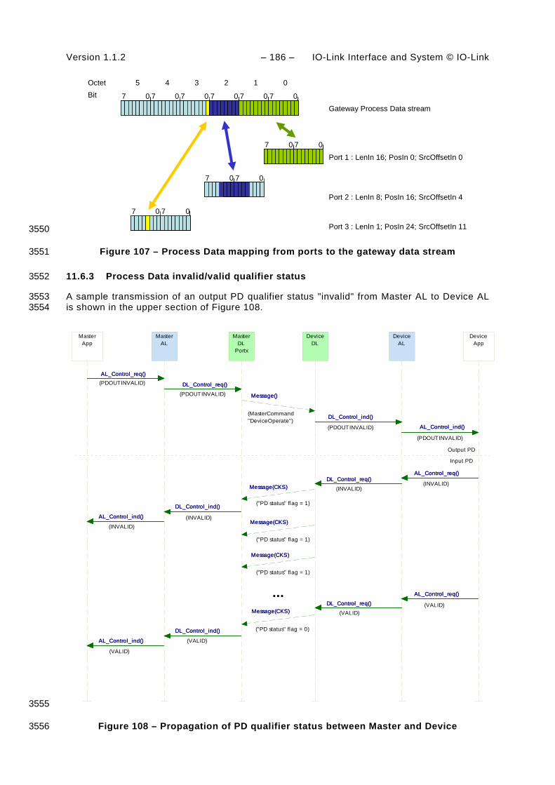
Version 1.1.2 – 186 – IO-Link Interface and System © IO-Link
000000 77 7 77 7
012345BitOctet
00 77
00 77
Port 1 : LenIn 16; PosIn 0; SrcOffsetIn 0
Port 2 : LenIn 8; PosIn 16; SrcOffsetIn 4
00 77
Port 3 : LenIn 1; PosIn 24; SrcOffsetIn 11
Gateway Process Data stream
3550
Figure 107 – Process Data mapping from ports to the gateway data stream 3551
11.6.3 Process Data invalid/valid qualifier status 3552
A sample transmission of an output PD qualifier status "invalid" from Master AL to Device AL 3553 is shown in the upper section of Figure 108. 3554
MasterApp
MasterAL
AL_Control_req()
AL_Control_ind()
AL_Control_ind()
AL_Control_req()
AL_Control_ind()
AL_Control_ind()
DL_Control_req()
MasterDL
Portx
DL_Control_ind()
DL_Control_ind()
DL_Control_req()
DL_Control_ind()
DL_Control_ind()
Message()
DeviceDL
Message()
Message(CKS)
Message(CKS)
Message(CKS)
Message(CKS)
Message(CKS)
Message(CKS)
Message(CKS)
Message(CKS)
DL_Control_ind()
DeviceAL
DL_Control_req()
DL_Control_req()
DL_Control_ind()
DL_Control_req()
DL_Control_req()
AL_Control_ind()
DeviceApp
AL_Control_ind()
AL_Control_req()
AL_Control_req()
AL_Control_req()
AL_Control_req()
(PDOUTINVALID)
(PDOUTINVALID)
(MasterCommand"DeviceOperate")
(PDOUTINVALID)
(PDOUTINVALID)
(INVALID)(INVALID)
("PD status" flag = 1)
(INVALID)(INVALID)
(VALID)(VALID)
(VALID)
(VALID)
...
Output PD
Input PD
("PD status" flag = 1)
("PD status" flag = 1)
("PD status" flag = 0)
3555
Figure 108 – Propagation of PD qualifier status between Master and Device 3556

IO-Link Interface and System © IO-Link – 187 – Version 1.1.2
The Master informs the Device about the output Process Data qualifier status "valid/invalid" 3557 by sending MasterCommands (see Table B.2) to the Direct Parameter page 1 (see 7.3.7.1). 3558
For input Process Data the Device sends the Process Data qualifier status in every single 3559 message as the "PD status" flag in the Checksum / Status (CKS) octet (see A.1.5) of the 3560 Device message. A sample transmission of the input PD qualifier status "valid" from Device 3561 AL to Master AL is shown in the lower section of Figure 108. 3562
Any perturbation while in interleave transmission mode leads to an input or output Process 3563 Data qualifier status "invalid" indication respectively 3564
11.7 Port and Device configuration tool (PDCT) 3565
11.7.1 General 3566
Figure 93 and Figure 106 demonstrate the necessity of a tool to configure ports, parameterize 3567 the Device, display diagnosis information, and provide identification and maintenance 3568 information. Depending on the degree of integration into a fieldbus system, the PDCT func-3569 tions can be reduced, for example if the port configuration can be achieved via the field 3570 device description file of the particular fieldbus. 3571
The PDCT functionality can be integrated partially (navigation, parameter transfer, etc.) or 3572 completely into the engineering tool of the particular fieldbus. 3573
11.7.2 Basic layout examples 3574
Figure 109 shows one example of a PDCT display layout. 3575
Toplevel…- Master- Port 1: Device A- Port 2: Device B- …- Port n: Device Z
Toplevel…- Master- Port 1: Device A- Port 2: Device B- …- Port n: Device Z
Device CatalogTopology
Layout of this windowdefined by the IODD ofthe connected Device
Layout of this windowdefined by the IODD ofthe connected Device
VendorVendor 1Vendor 2…Vendor n
VendorVendor 1Vendor 2…Vendor n
MonitoringIdentification Parameter Diagnosis Process Data
DeviceDevice aDevice bDevice c…Device z
DeviceDevice aDevice bDevice c…Device z
3576
Figure 109 – Example 1 of a PDCT display layout 3577
The PDCT display should always provide a navigation window for a project or a network 3578 topology, a window for the particular view on a chosen Device that is defined by its IODD, and 3579 a window for the available Devices based on the installed IODD files. 3580
Figure 110 shows another example of a PDCT display layout. 3581

Version 1.1.2 – 188 – IO-Link Interface and System © IO-Link
Toplevel…- Master- Port 1:
- Device A- Port 2:
- Device B- …- Port n:
- Device Z
Toplevel…- Master- Port 1:
- Device A- Port 2:
- Device B- …- Port n:
- Device Z
Vendor 1- Device a V1.03- Device b V1.23- Device c V2.00- …
Vendor 2- Device aa V0.99- Device bb V1.1.2- …
…Vendor n- Device xxx V2.3.04- Device yyy V1.3- Device zzz V123
Vendor 1- Device a V1.03- Device b V1.23- Device c V2.00- …
Vendor 2- Device aa V0.99- Device bb V1.1.2- …
…Vendor n- Device xxx V2.3.04- Device yyy V1.3- Device zzz V123
Device LibraryProject Tree Menu
Layout of this windowdefined by the IODD ofthe connected Device
Identification
Monitoring
Parameter
Diagnosis
Process Data
Parameter
3582
Figure 110 – Example 2 of a PDCT display layout 3583
NOTE Further information can be retrieved from IEC/TR 62453-61. 3584
11.8 Gateway application 3585
11.8.1 General 3586
The Gateway application depends on the individual host system (fieldbus, PLC, etc.) the 3587 Master applications are embedded in. It is the responsibility of the individual system to specify 3588 the mapping of the Master services and variables. 3589
11.8.2 Changing Device configuration including Data Storage 3590
After each change of Device configuration/parameterization (CVID and/or CDID, see 9.2.2.2), 3591 the associated previously stored data set within the Master shall be cleared or marked invalid 3592 via the variable DS_Delete. 3593
11.8.3 Parameter server and recipe control 3594
The Master may combine the entire parameter sets of the connected Devices together with all 3595 other relevant data for its own operation, and make this data available for higher level 3596 applications. For example, this data may be saved within a parameter server which may be 3597 accessed by a PLC program to change recipe parameters, thus supporting flexible 3598 manufacturing. 3599
NOTE The structure of the data exchanged between the Master and the parameter server is outside the scope of 3600 this standard. 3601
11.8.4 Anonymous parameters 3602
An alternative to using a Port and Device Configuration Tool is necessary for some gateway 3603 interfaces. For these interfaces, it is recommended that the gateway interface allows the host 3604 to send it a block of 10 unnamed octets of Device configuration data for each Device attached 3605 to the Master. The gateway interface will then use the AL_Write service to deliver the octets 3606 for each Device to Direct Parameter page 2 of the associated Device. 3607
NOTE Integration specifications are out of the scope of this standard. 3608
This approach is shown in Figure 111. 3609

IO-Link Interface and System © IO-Link – 189 – Version 1.1.2
Device
Application
Device
Application
Fieldbus interface
PLC / Host
Port 1 Port n
Fieldbus controller
Gateway application
Master
Field device description fileof the Master
Master as afield device
Anonymous parameter ValuePort0
9
0x??
0x??… …
0
9
0x??
0x??… …
0
9
0x??
0x??… …
0
9
0x78
0xB9… …1
0
9
0x3A
0x23… …n
Stored within Direct Parameterpage 2
1
2
n
Usermanual
Values takenfrom user manual
3610
Figure 111 – Alternative Device configuration 3611
11.8.5 Virtual port mode DIwithSDCI 3612
This optional operational mode provides a possibility to use a Device with SIO capability in 3613 the DIwithSDCI mode and allow the higher level system (for example PLC) to exchange On-3614 request Data acyclically. Preferably, this will take place when parameters are to be changed, 3615 at production stop, or diagnosis intervals. 3616
This operational mode simplifies the control program due to the omission of configuration 3617 before and after an acyclic access. 3618
In principle the gateway application realizes this operational mode virtually. It is solely in a 3619 position to decide within the individual states what the next steps can be. 3620
The CM does not know this operational mode. The gateway application reads the 3621 configuration data hold by the CM and uses services from SM and AL to realize this 3622 operational mode. 3623
The following rules shall be observed when implementing DIwithSDCI. 3624
• The DI signal of the Device is not valid during the acyclic access of the gateway 3625 application. 3626
• It is likely that an invalid DI signal is detected very late. Thus, only after the next acyclic 3627 access an Event "PDInvalid" can be raised and wire break or Device replacement can be 3628 detected. 3629
• The access will consume more time due to establishing communication and fallback 3630 procedures including Data Storage. 3631

Version 1.1.2 – 190 – IO-Link Interface and System © IO-Link
• The InspectionLevel shall at least comprise TYPE_COMP in order to detect an illegal 3632 Device. 3633
The state diagram in Figure 112 shows the individual states for the virtual operational mode 3634 DIwithSDCI. 3635
Idle_0
/Initialization
Check_Config_1
[Service received]/T1[Service received]/T1
[InspLevel_OK]/T3
DwS_Startup_2
[InspLevel_OK]/T3
[PreOperate]/T5
DwS_Await_Resp_3
[PreOperate]/T5
DwS_Fallback_4
[Service_complete]/T7[Service_complete]/T7
[Fallback_OK]/T9
Build_Service_Resp_5
[Error_any]/T8
[Error_any]/T6
[Error_any]/T4
[InspLevel_LOW]/T2
[Service response ready]/T10
[Fallback_OK]/T9
[Error_any]/T8
[Error_any]/T6
[Error_any]/T4
[InspLevel_LOW]/T2
[Service response ready]/T10
3636
Figure 112 – Virtual port mode "DIwithSDCI" 3637
Table 104 shows the states and transitions of the virtual port mode "DIwithSDCI". 3638
Table 104 – State transitions of the state machine "DIwithSDCI" 3639
STATE NAME STATE DESCRIPTION
Idle_0 For the higher level control program the port is configured for the operational mode DIwithSDCI and waits on service requests.
Check_Config_1 Within this state the InspectionLevel of the port is checked for a sufficient level.
DwS_StartUp_2 Within this state a complete startup until the PREOPERATE state is performed. This can include Data Storage and Event handling.
DwS_Await_Resp_3 Wait on responses (AL-Read.rsp or AL-Write.rsp).
DwS_FallBack_4 After accomplishing the services, the Device is switched back to the SIO mode via the MasterCommand "Fallback" and the port will be configured as a DI.
Build_Service_Resp_5 The service response (positive or negative) will be created to finalize the service to the higher level control program.
3640 TRANSITION SOURCE
STATE TARGET STATE
ACTION
T1 0 1 -
T2 1 5 -
T3 1 2 Invoke SM_SetPortConfig (to COMx)
T4 2 5 Invoke SM_SetPortConfig (to DI)

IO-Link Interface and System © IO-Link – 191 – Version 1.1.2
TRANSITION SOURCE STATE
TARGET STATE
ACTION
T5 2 3 Invoke Service (AL_Read.req oder AL_Write.req)
T6 3 5 Invoke SM_SetPortConfig (to DI)
T7 3 4 -
T8 4 5 Invoke SM_SetPortConfig (to DI)
T9 4 5 Invoke SM_SetPortConfig (to DI)
T10 5 0 Invoke corresponding AL service response 3641
INTERNAL ITEMS TYPE DEFINITION
InspLevel_LOW Bool The necessary InspectionLevel is not configured in order to detect the correct Device.
InspLevel_OK Bool The necessary InspectionLevel is configured to detect the correct Device.
PreOperate Bool State PREOPERATE is established
Service_complete Bool The gateway application received AL_Read.rsp or AL_Write.rsp
Fallback_OK Bool Fallback has been accomplished successfully
Error_any Bool Any error will quit this state
3642

Version 1.1.2 – 192 – IO-Link Interface and System © IO-Link
Annex A 3643 (normative) 3644
3645 Codings, timing constraints, and errors 3646
A.1 General structure and encoding of M-sequences 3647
A.1.1 Overview 3648
The general concept of M-sequences is outlined in 7.3.3.2. Subclauses A.1.2 to A.1.6 provide 3649 a detailed description of the individual elements of M-sequences. 3650
A.1.2 M-sequence control (MC) 3651
The Master indicates the manner the user data (see A.1.4) shall be transmitted in an M-3652 sequence control octet. This indication includes the transmission direction (read or write), the 3653 communication channel, and the address (offset) of the data on the communication channel. 3654 The structure of the M-sequence control octet is shown in Figure A.1. 3655
R / WCommunication
channel Address
Bit 0Bit 7 3656
Figure A.1 – M-sequence control 3657
Bit 0 to 4: Address 3658
These bits indicate the address, i.e. the octet offset of the user data on the specified 3659 communication channel (see also Table A.1). In case of an ISDU channel, these bits are used 3660 for flow control of the ISDU data. The address, which means in this case the position of the 3661 user data within the ISDU, is only available indirectly (see 7.3.6.2). 3662
Bit 5 to 6: Communication channel 3663 These bits indicate the communication channel for the access to the user data. The defined 3664 values for the communication channel parameter are listed in Table A.1. 3665
Table A.1 – Values of communication channel 3666
Value Definition
0 Process
1 Page
2 Diagnosis
3 ISDU
Bit 7: R/W 3667
This bit indicates the transmission direction of the user data on the selected communication 3668 channel, i.e. read access (transmission of user data from Device to Master) or write access 3669 (transmission of user data from Master to Device). The defined values for the R/W parameter 3670 are listed in Table A.2. 3671
Table A.2 – Values of R/W 3672
Value Definition
0 Write access
1 Read access
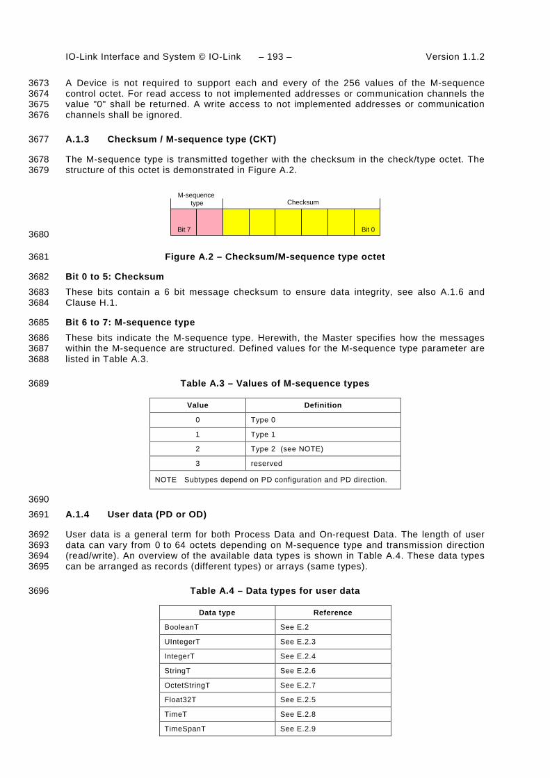
IO-Link Interface and System © IO-Link – 193 – Version 1.1.2
A Device is not required to support each and every of the 256 values of the M-sequence 3673 control octet. For read access to not implemented addresses or communication channels the 3674 value "0" shall be returned. A write access to not implemented addresses or communication 3675 channels shall be ignored. 3676
A.1.3 Checksum / M-sequence type (CKT) 3677
The M-sequence type is transmitted together with the checksum in the check/type octet. The 3678 structure of this octet is demonstrated in Figure A.2. 3679
M-sequencetype Checksum
Bit 0Bit 7 3680
Figure A.2 – Checksum/M-sequence type octet 3681
Bit 0 to 5: Checksum 3682 These bits contain a 6 bit message checksum to ensure data integrity, see also A.1.6 and 3683 Clause H.1. 3684
Bit 6 to 7: M-sequence type 3685
These bits indicate the M-sequence type. Herewith, the Master specifies how the messages 3686 within the M-sequence are structured. Defined values for the M-sequence type parameter are 3687 listed in Table A.3. 3688
Table A.3 – Values of M-sequence types 3689
Value Definition
0 Type 0
1 Type 1
2 Type 2 (see NOTE)
3 reserved
NOTE Subtypes depend on PD configuration and PD direction.
3690 A.1.4 User data (PD or OD) 3691
User data is a general term for both Process Data and On-request Data. The length of user 3692 data can vary from 0 to 64 octets depending on M-sequence type and transmission direction 3693 (read/write). An overview of the available data types is shown in Table A.4. These data types 3694 can be arranged as records (different types) or arrays (same types). 3695
Table A.4 – Data types for user data 3696
Data type Reference
BooleanT See E.2
UIntegerT See E.2.3
IntegerT See E.2.4
StringT See E.2.6
OctetStringT See E.2.7
Float32T See E.2.5
TimeT See E.2.8
TimeSpanT See E.2.9

Version 1.1.2 – 194 – IO-Link Interface and System © IO-Link
The detailed coding of the data types can be found in Annex E. 3697
A.1.5 Checksum / status (CKS) 3698
The checksum/status octet is part of the reply message from the Device to the Master. Its 3699 structure is shown in Figure A.3. It comprises a 6 bit checksum, a flag to indicate valid or 3700 invalid Process Data, and an Event flag. 3701
PDstatus Checksum
Eventflag
Bit 0Bit 7 3702
Figure A.3 – Checksum/status octet 3703
Bit 0 to 5: Checksum 3704 These bits contain a 6 bit checksum to ensure data integrity of the reply message. See also 3705 A.1.6 and Clause H.1. 3706
Bit 6: PD status 3707
This bit indicates whether the Device can provide valid Process Data or not. Defined values 3708 for the parameter are listed in Table A.5. 3709
This PD status flag shall be used for Devices with input Process Data. Devices with output 3710 Process Data shall always indicate "Process Data valid". 3711
If the PD status flag is set to “Process Data invalid” within a message, all the input Process 3712 Data of the complete Process Data cycle are invalid. 3713
Table A.5 – Values of PD status 3714
Value Definition
0 Process Data valid
1 Process Data invalid
3715 Bit 7: Event flag 3716
This bit indicates a Device initiative for the data category "Event" to be retrieved by the 3717 Master via the diagnosis communication channel (see Table A.1). The Device can report 3718 diagnosis information such as errors, warnings or notifications via Event response messages. 3719 Permissible values for the parameter are listed in Table A.6. 3720
Table A.6 – Values of the Event flag 3721
Value Definition
0 No Event
1 Event
3722 A.1.6 Calculation of the checksum 3723
The message checksum provides data integrity protection for data transmission from Master 3724 to Device and from Device to Master. Each UART data octet is protected by the UART parity 3725 bit (see Figure 18). Besides this individual data octet protection, all of the UART data octets in 3726 a message are XOR (exclusive or) processed octet by octet. The check/type octet is included 3727 with checksum bits set to "0". The resulting checksum octet is compressed from 8 to 6 bit in 3728 accordance with the conversion procedure in Figure A.4 and its associated formulas (see 3729

IO-Link Interface and System © IO-Link – 195 – Version 1.1.2
equations in (A.1)). The 6 bit compressed "Checksum6" is entered into the checksum/ M-3730 sequence type octet (see Figure A.2). The same procedure takes place to secure the 3731 message from the Device to the Master. In this case the compressed checksum is entered 3732 into the checksum/status octet (see Figure A.3). 3733
A seed value of 0x52 is used for the checksum calculation across the message. It is XORed 3734 with the first octet of the message (MC). 3735
0x52Seed value
MC
CKT
...
Octet n
Message
XOR processing
+
+ +
+ + + +
Checksum 8
Checksum 6
3736
Figure A.4 – Principle of the checksum calculation and compression 3737
The set of equations in (A.1) define the compression procedure from 8 to 6 bit in detail. 3738
D56 = D78 xor D58 xor D38 xor D18
D46 = D68 xor D48 xor D28 xor D08
D36 = D78 xor D68
D26 = D58 xor D48
D16 = D38 xor D28
D06 = D18 xor D08
(A.1)
A.2 M-sequence types 3739
A.2.1 Overview 3740
Process Data and On-request Data use separate cyclic and acyclic communication channels 3741 (see Figure 7) to ensure scheduled and deterministic delivery of Process Data while delivery 3742 of On-request Data does not have consequences on the Process Data transmission 3743 performance. 3744
Within SDCI, M-sequences provide the access to the communication channels via the M-3745 sequence Control octet. The number of different M-sequence types meets the various 3746 requirements of sensors and actuators regarding their Process Data width. See Figure 37 for 3747 an overview of the available M-sequence types that are specified in A.2.2 to A.2.5. See A.2.6 3748 for rules on how to use the M-sequence types. 3749
A.2.2 M-sequence TYPE_0 3750
M-sequence TYPE_0 is mandatory for all Devices. 3751
M-sequence TYPE_0 only transmits On-request Data. One octet of user data is read or 3752 written per cycle. This M-sequence is shown in Figure A.5. 3753

Version 1.1.2 – 196 – IO-Link Interface and System © IO-Link
TYPE_0
MC CKT
OD CKS
Master read message
Device reply message
MC CKT OD
CKS
Master write message
Device reply message
3754
Figure A.5 – M-sequence TYPE_0 3755
A.2.3 M-sequence TYPE_1_x 3756
M-sequence TYPE_1_x is optional for all Devices. 3757
M-sequence TYPE_1_1 is shown in Figure A.6. 3758
TYPE_1_1
PD1
MC CKT
CKS
Master read message
Device reply message
MC CKT
CKS
Master write message
Device reply message
PD0
PD1PD0
3759
Figure A.6 – M-sequence TYPE_1_1 3760
Two octets of Process Data are read or written per cycle. Address (bit offset) belongs to the 3761 process communication channel (see A.2.1). 3762
In case of interleave mode (see 7.3.4.2) and odd-numbered PD length the remaining octets 3763 within the messages are padded with 0x00. 3764
M-sequence TYPE_1_2 is shown in Figure A.7. Two octets of On-request Data are read or 3765 written per cycle. 3766
TYPE_1_2
MC CKT
OD0 CKS
Master read message
Device reply message
MC CKT
OD1
CKS
Master write message
Device reply message
OD0 OD1
3767
Figure A.7 – M-sequence TYPE_1_2 3768

IO-Link Interface and System © IO-Link – 197 – Version 1.1.2
For write access to On-request Data via the page and diagnosis communication channels, 3769 only the first octet of On-request Data is evaluated. The Device shall ignore the remaining 3770 octets. The Master shall send all other ODs with "0x00". 3771
M-sequence TYPE_1_V providing variable (extendable) message length is shown in Figure 3772 A.8. A number of m octets of On-request Data are read or written per cycle. 3773
For write access to On-request Data via the page and diagnosis communication channels, 3774 only the first octet (OD0) of On-request Data is evaluated. The Device shall ignore the 3775 remaining octets. The Master shall send all other ODs with "0x00". 3776
TYPE_1_V
MC CKT
OD0 CKS
Master read message
Device reply message
MC CKT
ODm-1
CKS
Master write message
Device reply message
OD0 ODm-1
3777
Figure A.8 – M-sequence TYPE_1_V 3778
A.2.4 M-sequence TYPE_2_x 3779
M-sequence TYPE_2_x is optional for all Devices. M-sequences TYPE_2_1 through 3780 TYPE_2_6 are defined. M-sequence TYPE_2_V provides variable (extendable) message 3781 length. M-sequence TYPE_2_x transmits Process Data and On-request Data in one message. 3782 The number of process and On-request Data read or written in each cycle depends on the 3783 type. The Address parameter (see Figure A.1) belongs in this case to the on-request 3784 communication channel. The Process Data address is specified implicitly starting at "0". The 3785 format of Process Data is characterizing the M-sequence TYPE_2_x. 3786
M-sequence TYPE_2_1 transmits one octet of read Process Data and one octet of read or 3787 write On-request Data per cycle. This M-sequence type is shown in Figure A.9. 3788
TYPE_2_1
MC CKT
OD CKS
Master read message
Device reply message
MC CKT
CKS
Master write message
Device reply message
OD
PD
PD
3789
Figure A.9 – M-sequence TYPE_2_1 3790
M-sequence TYPE_2_2 transmits 2 octets of read Process Data and one octet of On-request 3791 Data per cycle. This M-sequence type is shown in Figure A.10. 3792

Version 1.1.2 – 198 – IO-Link Interface and System © IO-Link
TYPE_2_2
MC CKT
OD CKS
Master read message
Device reply message
MC CKT
CKS
Master write message
Device reply message
OD
PD0
PD0
PD1
PD1
3793
Figure A.10 – M-sequence TYPE_2_2 3794
M-sequence TYPE_2_3 transmits one octet of write Process Data and one octet of read or 3795 write on-reqest data per cycle. This M-sequence type is shown in Figure A.11. 3796
TYPE_2_3
MC CKT
OD CKS
Master read message
Device reply message
MC CKT
CKS
Master write message
Device reply message
ODPD
PD
3797
Figure A.11 – M-sequence TYPE_2_3 3798
M-sequence TYPE_2_4 transmits 2 octets of write Process Data and one octet of read or 3799 write On-request Data per cycle. This M-sequence type is shown in Figure A.12 3800
TYPE_2_4
MC CKT
OD CKS
Master read message
Device reply message
MC CKT
CKS
Master write message
Device reply message
ODPD0
PD0 PD1
PD1
3801
Figure A.12 – M-sequence TYPE_2_4 3802
M-sequence TYPE_2_5 transmits one octet of write and read Process Data and one octet of 3803 read or write On-request Data per cycle. This M-sequence type is shown in Figure A.13. 3804

IO-Link Interface and System © IO-Link – 199 – Version 1.1.2
TYPE_2_5
MC CKT
OD CKS
Master read message
Device reply message
MC CKT
CKS
Master write message
Device reply message
ODPD
PD
PD
PD
3805
Figure A.13 – M-sequence TYPE_2_5 3806
M-sequence TYPE_2_6 transmits 2 octets of write and read Process Data and one octet of 3807 read or write On-request Data per cycle. This M-sequence type is shown in Figure A.14. 3808
TYPE_2_6
MC CKT
OD
Master read message
Device reply message
MC CKT
CKS
Master write message
Device reply message
PD0
PD0
PD0
PD0
PD1
PD1 CKS
PD1 OD
PD1
3809
Figure A.14 – M-sequence TYPE_2_6 3810
M-sequence TYPE_2_V transmits the entire write (read) ProcessDataIn n (k) octets per cycle. 3811 The range of n (k) is 0 to 32. Either PDin or PDout are not existing when n = 0 or k = 0. 3812 TYPE_2_V also transmits m octets of (segmented) read or write On-request Data per cycle 3813 using the address in Figure A.1. Permitted values for m are 1, 2, 8, and 32. This variable M-3814 sequence type is shown in Figure A.15. 3815
TYPE_2_V
OD0 ODm-1 PD0 CKS
Master read message
Device reply message
Master write message
Device reply message
PDk-1
PDn-1
PD0 CKSPDk-1
OD0 ODm-1
MC CKT PD0 PDn-1
MC CKT PD0
3816
Figure A.15 – M-sequence TYPE_2_V 3817
For write access to On-request Data via the page and diagnosis communication channels, 3818 only the first octet (OD0) of On-request Data is evaluated. The Device shall ignore the 3819 remaining octets. The Master shall send all other ODs with "0". 3820

Version 1.1.2 – 200 – IO-Link Interface and System © IO-Link
A.2.5 M-sequence type 3 3821
M-sequence type 3 is reserved and shall not be used. 3822
A.2.6 M-sequence type usage for STARTUP, PREOPERATE and OPERATE modes 3823
Table A.7 lists the M-sequence types for the STARTUP mode together with the minimum 3824 recovery time (Tinitcyc) that shall be observed for Master implementations (see A.3.9). The M-3825 sequence code refers to the coding in B.1.4. 3826
Table A.7 – M-sequence types for the STARTUP mode 3827
STARTUP M-sequence
code
On-request Data M-sequence type Minimum recovery time
Octets TBIT
n/a 1 TYPE_0 100
3828 Table A.8 lists the M-sequence types for the PREOPERATE mode together with the minimum 3829 recovery time (Tinitcyc) that shall be observed for Master implementations. 3830
Table A.8 – M-sequence types for the PREOPERATE mode 3831
PREOPERATE M-sequence
code
On-request Data M-sequence type Minimum recovery time
Octets TBIT
0 1 TYPE_0 100
1 2 TYPE_1_2 100
2 8 TYPE_1_V 210
3 32 TYPE_1_V 550
NOTE The minimum recovery time in PREOPERATE mode is a requirement for the Master.
3832 Table A.9 lists the M-sequence types for the OPERATE mode for legacy Devices. The 3833 minimum cycle time for Master in OPERATE mode is specified by the parameter 3834 "MinCycleTime" of the Device (see B.1.3). 3835
Table A.9 – M-sequence types for the OPERATE mode (legacy protocol) 3836
OPERATE M-sequence
code
On-request Data Process Data (PD) M-sequence type
Octets PDin PDout Legacy protocol (see [8])
0 1 0 0 TYPE_0
1 2 0 0 TYPE_1_2
don't care 2 3…32 octets 0…32 octets TYPE_1_1/1_2 (interleaved)
don't care 2 0…32 octets 3…32 octets TYPE_1_1/1_2 (interleaved)
don't care 1 1…8 bit 0 TYPE_2_1
don't care 1 9…16 bit 0 TYPE_2_2
don't care 1 0 1…8 bit TYPE_2_3
don't care 1 0 9…16 bit TYPE_2_4
don't care 1 1…8 bit 1…8 bit TYPE_2_5
3837

IO-Link Interface and System © IO-Link – 201 – Version 1.1.2
Table A.10 lists the M-sequence types for the OPERATE mode for Devices according to this 3838 specification. The minimum cycle time for Master in OPERATE mode is specified by the 3839 parameter MinCycleTime of the Device (see B.1.3). 3840
Table A.10 – M-sequence types for the OPERATE mode 3841
OPERATE M-sequence
code
On-request Data Process Data (PD) M-sequence type
Octets PDin PDout
0 1 0 0 TYPE_0
1 2 0 0 TYPE_1_2
6 8 0 0 TYPE_1_V
7 32 0 0 TYPE_1_V
0 2 3…32 octets 0…32 octets TYPE_1_1/1_2 interleaved
0 2 0…32 octets 3…32 octets TYPE_1_1/1_2 interleaved
0 1 1…8 bit 0 TYPE_2_1
0 1 9…16 bit 0 TYPE_2_2
0 1 0 1…8 bit TYPE_2_3
0 1 0 9…16 bit TYPE_2_4
0 1 1…8 bit 1…8 bit TYPE_2_5
0 1 9…16 bit 1…16 bit TYPE_2_6
0 1 1…16 bit 9…16 bit TYPE_2_6
4 1 0…32 octets 3…32 octets TYPE_2_V
4 1 3…32 octets 0…32 octets TYPE_2_V
5 2 >0 bit, octets ≥0 bit, octets TYPE_2_V
5 2 ≥0 bit, octets >0 bit, octets TYPE_2_V
6 8 >0 bit, octets ≥0 bit, octets TYPE_2_V
6 8 ≥0 bit, octets >0 bit, octets TYPE_2_V
7 32 >0 bit, octets ≥0 bit, octets TYPE_2_V
7 32 ≥0 bit, octets >0 bit, octets TYPE_2_V
3842
A.3 Timing constraints 3843
A.3.1 General 3844
The interactions of a Master and its Device are characterized by several time constraints that 3845 apply to the UART frame, Master and Device message transmission times, supplemented by 3846 response, cycle, delay, and recovery times. 3847
A.3.2 Bit time 3848
The bit time TBIT is the time it takes to transmit a single bit. It is the inverse value of the 3849 transmission rate (see equation (A.2)). 3850
TBIT = 1/(transmission rate) (A.2)
Values for TBIT are specified in Table 8. 3851

Version 1.1.2 – 202 – IO-Link Interface and System © IO-Link
A.3.3 UART frame transmission delay of Master (ports) 3852
The UART frame transmission delay t1 of a port is the duration between the end of the stop bit 3853 of a UART frame and the beginning of the start bit of the next UART frame. The port shall 3854 transmit the UART frames within a maximum delay of one bit time (see equation (A.3)). 3855
0 ≤ t1 ≤ 1 TBIT (A.3)
A.3.4 UART frame transmission delay of Devices 3856
The Device’s UART frame transmission delay t2 is the duration between the end of the stop 3857 bit of a UART frame and the beginning of the start bit of the next UART frame. The Device 3858 shall transmit the UART frames within a maximum delay of 3 bit times (see equation (A.4)). 3859
0 ≤ t2 ≤ 3 TBIT (A.4)
A.3.5 Response time of Devices 3860
The Device's response time tA is the duration between the end of the stop bit of a port's last 3861 UART frame being received and the beginning of the start bit of the first UART frame being 3862 sent. The Device shall observe a delay of at least one bit time but no more than 10 bit times 3863 (see equation (A.5)). 3864
1 TBIT ≤ tA ≤ 10 TBIT (A.5)
A.3.6 M-sequence time 3865
Communication between a port and and its associated Device takes place in a fixed schedule, 3866 called the M-sequence time (see equation (A.6)). 3867
t M-sequence = (m+n) * 11 * TBIT + tA + (m-1) * t1 + (n-1) * t2 (A.6)
In this formula, m is the number of UART frames sent by the port to the Device and n is the 3868 number of UART frames sent by the Device to the port. The formula can only be used for 3869 estimates as the times t1 and t2 may not be constant. 3870
Figure A.16 demonstrates the timings of an M-sequence consisting of a Master (port) 3871 message and a Device message. 3872
UARTframe
UARTframe
UARTframe
UARTframe
UARTframe
UARTframe
t1 t1
t2 t2tA
tM-sequence
Port(Master)
Device
3873
Figure A.16 – M-sequence timing 3874
A.3.7 Cycle time 3875
The cycle time tCYC (see equation (A.7)) depends on the Device's parameter “MinCycleTime” 3876 and the design and implementation of a Master and the number of ports. 3877

IO-Link Interface and System © IO-Link – 203 – Version 1.1.2
tCYC = tM-sequence + tidle (A.7)
The adjustable Device parameter “MasterCycleTime” can be used for the design of a Device 3878 specific technology such as an actuator to derive the timing conditions for a default 3879 appropriate action such as de-activate or de-energize the actuator (see 7.3.3.5 3880 "MaxCycleTime", 10.2, and 10.7.3). 3881
Table A.11 lists recommended minimum cycle time values for the specified transmission mode 3882 of a port. The values are calculated based on M-sequence Type_2_1. 3883
Table A.11 – Recommended MinCycleTimes 3884
Transmission mode tCYC
COM1 18,0 ms
COM2 2,3 ms
COM3 0,4 ms
A.3.8 Idle time 3885
The idle time tidle results from the configured cycle time tCYC and the M-sequence time 3886 tM-sequence. With reference to a port, it comprises the time between the end of the message of 3887 a Device and the beginning of the next message from the Master (port). 3888
The idle time shall be long enough for the Device to become ready to receive the next 3889 message. 3890
A.3.9 Recovery time 3891
The Master shall wait for a recovery time tinitcyc between any two subsequent acyclic Device 3892 accesses while in the STARTUP or PREOPERATE phase (see A.2.6). 3893
A.4 Errors and remedies 3894
A.4.1 UART errors 3895
A.4.1.1 Parity errors 3896
The UART parity bit (see Figure 18) and the checksum (see A.1.6) are two independent 3897 mechanisms to secure the data transfer. This means that for example two bit errors in 3898 different octets of a message, which are resulting in the correct checksum, can also be 3899 detected. Both mechanisms lead to the same error processing. 3900
Remedy: The Master shall repeat the Master message 2 times (see 7.2.2.1). Devices shall 3901 reject all data with detected errors and create no reaction. 3902
A.4.1.2 UART framing errors 3903
The conditions for the correct detection of a UART frame are specified in 5.3.3.2. Error 3904 processing shall take place whenever perturbed signal shapes or incorrect timings lead to an 3905 invalid UART stop bit. 3906
Remedy: See A.4.1.1. 3907

Version 1.1.2 – 204 – IO-Link Interface and System © IO-Link
A.4.2 Wake-up errors 3908
The wake-up current pulse is specified in 5.3.3.3 and the wake-up procedures in 7.3.2.1. 3909 Several faults may occur during the attempts to establish communication. 3910
Remedy: Retries are possible. See 7.3.2.1 for details. 3911
A.4.3 Transmission errors 3912
A.4.3.1 Checksum errors 3913
The checksum mechanism is specified in A.1.6. Any checksum error leads to an error 3914 processing. 3915
Remedy: See A.4.1.1. 3916
A.4.3.2 Timeout errors 3917
The diverse timing constraints with M-sequences are specified in A.3. Master (ports) and 3918 Devices are checking several critical timings such as lack of synchronism within messages. 3919
Remedy: See A.4.1.1. 3920
A.4.3.3 Collisions 3921
A collision occurs whenever the Master and Device are sending simultaneously due to an 3922 error. This error is interpreted as a faulty M-sequence. 3923
Remedy: See A.4.1.1. 3924
A.4.4 Protocol errors 3925
A protocol error occurs for example whenever the sequence of the segmented transmission of 3926 an ISDU is wrong (see flow control case in A.1.2). 3927
Remedy: Abort of service with ErrorType information (see Annex C). 3928
A.5 General structure and encoding of ISDUs 3929
A.5.1 Overview 3930
The purpose and general structure of an ISDU is specified in 7.3.6.1. Subclauses A.5.2 to 3931 A.5.7 provide a detailed description of the individual elements of an ISDU and some 3932 examples. 3933
A.5.2 I-Service 3934
Figure A.17 shows the structure of the I-Service octet. 3935
I-Service Length
Bit 0Bit 7 3936
Figure A.17 – I-Service octet 3937
Bits 0 to 3: Length 3938 The encoding of the nibble Length of the ISDU is specified in Table A.14 . 3939

IO-Link Interface and System © IO-Link – 205 – Version 1.1.2
Bits 4 to 7: I-Service 3940 The encoding of the nibble I-Service of the ISDU is specified in Table A.12. 3941
All other elements of the structure specified in 7.3.6.1 are transmitted as independent octets. 3942
Table A.12 – Definition of the nibble "I-Service" 3943
I-Service (binary)
Definition Index format
Master Device
0000 No Service No Service n/a
0001 Write Request Reserved 8-bit Index
0010 Write Request Reserved 8-bit Index and Subindex
0011 Write Request Reserved 16-bit Index and Subindex
0100 Reserved Write Response (-) none
0101 Reserved Write Response (+) none
0110 Reserved Reserved
0111 Reserved Reserved
1000 Reserved Reserved
1001 Read Request Reserved 8-bit Index
1010 Read Request Reserved 8-bit Index and Subindex
1011 Read Request Reserved 16-bit Index and Subindex
1100 Reserved Read Response (-) none
1101 Reserved Read Response (+) none
1110 Reserved Reserved
1111 Reserved Reserved
3944
Table A.13 specifies the syntax of the ISDUs. ErrorType can be found in Annex C. 3945
Table A.13 – ISDU syntax 3946
ISDU name ISDU structure
Write Request {I-Service(0x1), LEN, Index, [Data*], CHKPDU} ^ {I-Service(0x2), LEN, Index, Subindex, [Data*], CHKPDU} ^ {I-Service(0x3), LEN, Index, Index, Subindex, [Data*], CHKPDU}
Write Response (+) I-Service(0x5), Length(0x2), CHKPDU
Write Response (-) I-Service(0x4), Length(0x4), ErrorType, CHKPDU
Read Request {I-Service(0x9), Length(0x3), Index, CHKPDU} ^ {I-Service(0xA), Length(0x4), Index, Subindex, CHKPDU} ^ {I-Service(0xB), Length(0x5), Index, Index, Subindex, CHKPDU}
Read Response (+) I-Service(0xD), LEN, [Data*], CHKPDU
Read Response (-) I-Service(0xC), Length(0x4), ErrorType, CHKPDU
Key
LEN = {Length(0x1), ExtLength} ^ {Length}
3947
A.5.3 Extended length (ExtLength) 3948
The number of octets transmitted in this I-Service, including all protocol information (6 octets), 3949 is specified in the “Length” element of an ISDU. If the total length is more than 15 octets, the 3950
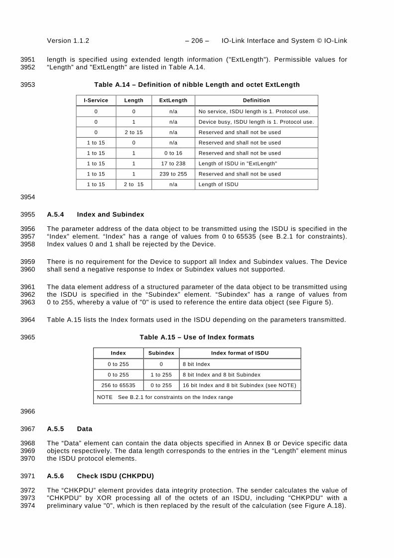
Version 1.1.2 – 206 – IO-Link Interface and System © IO-Link
length is specified using extended length information ("ExtLength"). Permissible values for 3951 “Length” and "ExtLength" are listed in Table A.14. 3952
Table A.14 – Definition of nibble Length and octet ExtLength 3953
I-Service Length ExtLength Definition
0 0 n/a No service, ISDU length is 1. Protocol use.
0 1 n/a Device busy, ISDU length is 1. Protocol use.
0 2 to 15 n/a Reserved and shall not be used
1 to 15 0 n/a Reserved and shall not be used
1 to 15 1 0 to 16 Reserved and shall not be used
1 to 15 1 17 to 238 Length of ISDU in "ExtLength"
1 to 15 1 239 to 255 Reserved and shall not be used
1 to 15 2 to 15 n/a Length of ISDU
3954
A.5.4 Index and Subindex 3955
The parameter address of the data object to be transmitted using the ISDU is specified in the 3956 “Index” element. “Index” has a range of values from 0 to 65535 (see B.2.1 for constraints). 3957 Index values 0 and 1 shall be rejected by the Device. 3958
There is no requirement for the Device to support all Index and Subindex values. The Device 3959 shall send a negative response to Index or Subindex values not supported. 3960
The data element address of a structured parameter of the data object to be transmitted using 3961 the ISDU is specified in the “Subindex” element. “Subindex” has a range of values from 3962 0 to 255, whereby a value of "0" is used to reference the entire data object (see Figure 5). 3963
Table A.15 lists the Index formats used in the ISDU depending on the parameters transmitted. 3964
Table A.15 – Use of Index formats 3965
Index Subindex Index format of ISDU
0 to 255 0 8 bit Index
0 to 255 1 to 255 8 bit Index and 8 bit Subindex
256 to 65535 0 to 255 16 bit Index and 8 bit Subindex (see NOTE)
NOTE See B.2.1 for constraints on the Index range
3966
A.5.5 Data 3967
The “Data” element can contain the data objects specified in Annex B or Device specific data 3968 objects respectively. The data length corresponds to the entries in the “Length” element minus 3969 the ISDU protocol elements. 3970
A.5.6 Check ISDU (CHKPDU) 3971
The “CHKPDU” element provides data integrity protection. The sender calculates the value of 3972 "CHKPDU" by XOR processing all of the octets of an ISDU, including "CHKPDU" with a 3973 preliminary value "0", which is then replaced by the result of the calculation (see Figure A.18). 3974

IO-Link Interface and System © IO-Link – 207 – Version 1.1.2
+
I-Service
ExtLength
Index
Subindex
Data 1
...
Length
Data n
CHKPDU = Checksum
I-Service
ExtLength
Index
Subindex
Data 1
...
Length
Data n
CHKPDU = Checksum
+
+
+
+
+
+
Result = "0", otherwise perturbed bitsResult = "0", otherwise perturbed bits
XOR+
I-Service
ExtLength
Index
Subindex
Data 1
...
Length
Data n
1. CHKPDU = "0"2. CHKPDU = Checksum
I-Service
ExtLength
Index
Subindex
Data 1
...
Length
Data n
1. CHKPDU = "0"2. CHKPDU = Checksum
+
+
+
+
+
+
ChecksumChecksum
XOR
Prior to sending
Sender Receiver
3975
Figure A.18 – Check of ISDU integrity via CHKPDU 3976
The receiver checks whether XOR processing of all of the octets of the ISDU will lead to the 3977 result "0" (see Figure A.18). If the result is different from "0", error processing shall take 3978 place. See also A.1.6. 3979
A.5.7 ISDU examples 3980
Figure A.19 demonstrates typical examples of request formats for ISDUs, which are explained 3981 in the following paragraphs. 3982
8 Bit Index8 Bit Index andSubindex 16 Bit Index and
Subindex
I-Service
Index
Data 1 (MSO)
Data 2 (LSO)
CHKPDU
0101 I-Service
Index
Subindex
Data 1
CHKPDU
0110
Data 2
I-Service
Index
Subindex
Data 1
CHKPDU
0111
Data 2
Index
Request example 1 Request example 2 Request example 3 Request example 4
I-Service
ExtLength (n) 1)
Data 1
0001
Data 2
Index
CHKPDU
Data (n-4)
...
...
0000 0000
Request example 5
"Idle" request
3983
1) Overall ISDU ExtLength = n (1 to 238); Length = 1 ("0001") 3984
Figure A.19 – Examples of request formats for ISDUs 3985
The ISDU request in example 1 comprises one Index element allowing addressing from 3986 0 to 254 (see Table A.15). In this example the Subindex is "0" and the whole content of Index 3987 is Data 1 with the most significant octet (MSO) and Data 2 with the least significant octet 3988 (LSO). The total length is 5 ("0101"). 3989
The ISDU request in example 2 comprises one Index element allowing addressing from 0 to 3990 254 and the Subindex element allowing addressing an element of a data structure. The total 3991 length is 6 ("0110"). 3992

Version 1.1.2 – 208 – IO-Link Interface and System © IO-Link
The ISDU request in example 3 comprises two Index elements allowing to address from 256 3993 to 65535 (see Table A.15) and the Subindex element allowing to address an element of a data 3994 structure. The total length is 7 ("0111"). 3995
The ISDU request in example 4 comprises one Index element and the ExtLength element 3996 indicating the number of ISDU elements (n), permitting numbers from 17 to 238. In this case 3997 the Length element has the value "1". 3998
The ISDU request "Idle" in example 5 is used to indicate that no service is pending. 3999
Figure A.20 demonstrates typical examples of response ISDUs, which are explained in the 4000 following paragraphs. 4001
I-Service
Data 1 (MSO)
Data 2 (LSO)
CHKPDU
0100I-Service
CHKPDU
0010 1)
Response example 2Response example 1 Response example 3
I-Service
ExtLength (n) 2)
Data 1
0001
Data 2
CHKPDU
Data (n-3)
...
...
0000 0001
Response example 4
"Busy" response
4002
1) Minimum length = 2 ("0010") 4003 2) Overall ISDU ExtLength = n (17 to 238); 4004 Length = 1 ("0001") 4005
Figure A.20 – Examples of response ISDUs 4006
The ISDU response in example 1 shows the minimum value 2 for the Length element ("0010"). 4007
The ISDU response in example 2 shows two Data elements and a total number of 4 elements 4008 in the Length element ("0100"). Data 1 carries the most significant octet (MSO) and Data 2 4009 the least significant octet (LSO). 4010
The ISDU response in example 3 shows the ExtLength element indicating the number of ISDU 4011 elements (n), permitting numbers from 17 to 238. In this case the Length element has the 4012 value "1". 4013
The ISDU response "Busy" in example 4 is used when a Device is currently not able to 4014 respond to the read request of the Master due to the necessary preparation time for the 4015 response. 4016
Figure A.21 shows a typical example of both a read and a write request ISDU, which are 4017 explained in the following paragraphs. 4018
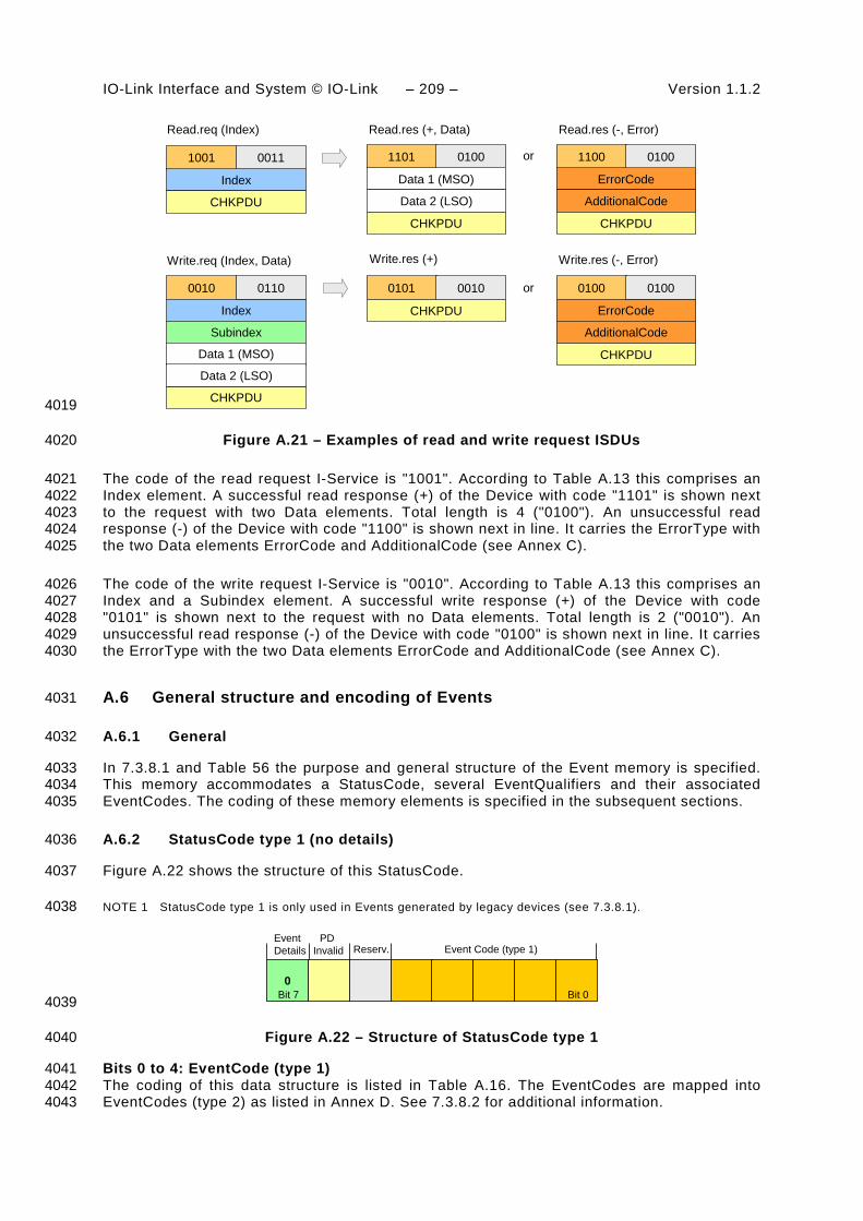
IO-Link Interface and System © IO-Link – 209 – Version 1.1.2
1001
Index
CHKPDU
0011
Read.req (Index)
0010
Index
Subindex
Data 1 (MSO)
CHKPDU
0110
Data 2 (LSO)
Write.req (Index, Data)
1101
Data 1 (MSO)
Data 2 (LSO)
CHKPDU
0100
Read.res (+, Data)
0101
CHKPDU
0010
Write.res (+)
1100
ErrorCode
AdditionalCode
CHKPDU
0100
Read.res (-, Error)
0100
ErrorCode
AdditionalCode
CHKPDU
0100
Write.res (-, Error)
or
or
4019
Figure A.21 – Examples of read and write request ISDUs 4020
The code of the read request I-Service is "1001". According to Table A.13 this comprises an 4021 Index element. A successful read response (+) of the Device with code "1101" is shown next 4022 to the request with two Data elements. Total length is 4 ("0100"). An unsuccessful read 4023 response (-) of the Device with code "1100" is shown next in line. It carries the ErrorType with 4024 the two Data elements ErrorCode and AdditionalCode (see Annex C). 4025
The code of the write request I-Service is "0010". According to Table A.13 this comprises an 4026 Index and a Subindex element. A successful write response (+) of the Device with code 4027 "0101" is shown next to the request with no Data elements. Total length is 2 ("0010"). An 4028 unsuccessful read response (-) of the Device with code "0100" is shown next in line. It carries 4029 the ErrorType with the two Data elements ErrorCode and AdditionalCode (see Annex C). 4030
A.6 General structure and encoding of Events 4031
A.6.1 General 4032
In 7.3.8.1 and Table 56 the purpose and general structure of the Event memory is specified. 4033 This memory accommodates a StatusCode, several EventQualifiers and their associated 4034 EventCodes. The coding of these memory elements is specified in the subsequent sections. 4035
A.6.2 StatusCode type 1 (no details) 4036
Figure A.22 shows the structure of this StatusCode. 4037
NOTE 1 StatusCode type 1 is only used in Events generated by legacy devices (see 7.3.8.1). 4038
0
EventDetails
PD Invalid Event Code (type 1)Reserv.
Bit 0Bit 7 4039
Figure A.22 – Structure of StatusCode type 1 4040
Bits 0 to 4: EventCode (type 1) 4041 The coding of this data structure is listed in Table A.16. The EventCodes are mapped into 4042 EventCodes (type 2) as listed in Annex D. See 7.3.8.2 for additional information. 4043

Version 1.1.2 – 210 – IO-Link Interface and System © IO-Link
Table A.16 – Mapping of EventCodes (type 1) 4044
EventCode (type 1)
EventCode (type2)
Instance Type Mode
****1 0xFF80 Application Notification Event single shot
***1* 0xFF80 Application Warning Event single shot
**1** 0x6320 Application Error Event single shot
*1*** 0xFF80 Application Error Event single shot
1**** 0xFF10 Application Error Event single shot
Key * Don't care type 2 See Table D.1 and Table D.2
4045 Bit 5: Reserved 4046 This bit is reserved and shall be set to zero in StatusCode type 1. 4047
Bit 6: Reserved 4048 NOTE 2 This bit is used in legacy protocol (see [8]) for PDinvalid indication. 4049 Bit 7: Event Details 4050 This bit indicates that no detailed Event information is available. It shall always be set to zero 4051 in StatusCode type 1. 4052
A.6.3 StatusCode type 2 (with details) 4053
Figure A.23 shows the structure of the StatusCode type 2. 4054
1
Reserv. Activated events
Bit 0Bit 7
EventDetails
4055
Figure A.23 – Structure of StatusCode type 2 4056
Bits 0 to 5: Activated Events 4057 Each bit is linked to an Event in the memory (see 7.3.8.1) as demonstrated in Figure A.24. 4058 Bit 0 is linked to Event 1, bit 1 to Event 2, etc. A bit with value "1" indicates that the 4059 corresponding EventQualifier and the EventCode have been entered in valid formats in the 4060 memory. A bit with value "0" indicates an invalid entry. 4061
1
Reserv. Activated events
StatusCode (type 2)
EventQualifier and EventCode 1
EventQualifier and EventCode 2
EventQualifier and EventCode 3
EventQualifier and EventCode 4
EventQualifier and EventCode 5
EventQualifier and EventCode 6
Bit 0Bit 7 Bit 5
EventDetails
4062
Figure A.24 – Indication of activated Events 4063

IO-Link Interface and System © IO-Link – 211 – Version 1.1.2
Bit 6: Reserved 4064 This bit is reserved and shall be set to zero. 4065
NOTE This bit is used in the legacy protocol version according to [8] for PDinvalid indication 4066 Bit 7: Event Details 4067 This bit indicates that detailed Event information is available. It shall always be set in 4068 StatusCode type 2. 4069
A.6.4 EventQualifier 4070
The structure of the EventQualifier is shown in Figure A.25. 4071
MODE INSTANCESOURCETYPE
Bit 0Bit 7 4072
Figure A.25 – Structure of the EventQualifier 4073
Bits 0 to 2: INSTANCE 4074 These bits indicate the particular source (instance) of an Event thus refining its evaluation on 4075 the receiver side. Permissible values for INSTANCE are listed in Table A.17. 4076
4077
Table A.17 – Values of INSTANCE 4078
Value Definition
0 Unknown
1 to 3 Reserved
4 Application
5 to 7 Reserved
4079 Bit 3: SOURCE 4080 This bit indicates the source of the Event. Permissible values for SOURCE are listed in Table 4081 A.18. 4082
Table A.18 – Values of SOURCE 4083
Value Definition
0 Device (remote)
1 Master (local)
4084 Bits 4 to 5: TYPE 4085 These bits indicate the Event category. Permissible values for TYPE are listed in Table A.19. 4086
Table A.19 – Values of TYPE 4087
Value Definition
0 Reserved
1 Notification
2 Warning
3 Error

Version 1.1.2 – 212 – IO-Link Interface and System © IO-Link
4088 Bits 6 to 7: MODE 4089 These bits indicate the Event mode. Permissible values for MODE are listed in Table A.20. 4090
Table A.20 – Values of MODE 4091
Value Definition
0 reserved
1 Event single shot
2 Event disappears
3 Event appears
4092 A.6.5 EventCode 4093
The EventCode entry contains the identifier of an actual Event. Permissible values for 4094 EventCode are listed in Annex D. 4095

IO-Link Interface and System © IO-Link – 213 – Version 1.1.2
Annex B 4096 (normative) 4097
4098 Parameter and commands 4099
B.1 Direct Parameter page 1 and 2 4100
B.1.1 Overview 4101
In principle, the designer of a Device has a large amount of space for parameters and 4102 commands as shown in Figure 5. However, small sensors with a limited number of parameters 4103 and limited resources are striving for a simple subset. SDCI offers the so-called Direct 4104 Parameter pages 1 and 2 with a simplified access method (page communication channel 4105 according to Table A.1) to meet this requirement. 4106
The range of Direct Parameters is structured as shown in Figure B.1. It is split into page 1 4107 and page 2. 4108
Communication control0x00 … 0x06
Identification0x07 … 0x0E
Application control0x0F
Device specific0x10 … 0x1F
Direct Parameter
Page 2:Device(individual orprofile)
Page 1:System and predefinedparametersand controls(fixed)
4109
Figure B.1 – Classification and mapping of Direct Parameters 4110
Page 1 ranges from 0x00 to 0x0F. It comprises the following categories of parameters: 4111
• Communication control 4112
• Identification parameter 4113
• Application control 4114
The Master application layer (AL) provides read only access to Direct Parameter page 1 as 4115 data objects (see 8.2.1) via Index 0. Single octets can be read via Index 0 and the 4116 corresponding Subindex. Subindex 1 indicates address 0x00 and Subindex 16 address 0x0F. 4117
Page 2 ranges from 0x10 to 0x1F. This page comprises parameters optionally used by the 4118 individual Device technology. The Master application layer (AL) provides read/write access to 4119 Direct Parameter page 2 in form of data objects (see 8.2.1) via Index 1. Single octets can be 4120 written or read via Index 1 and the corresponding Subindex. Subindex 1 indicates address 4121 0x10 and Subindex 16 address 0x1F. 4122
A Device shall always return the value "0" upon a read access to Direct Parameter addresses, 4123 which are not implemented (for example in case of reserved parameter addresses or not 4124

Version 1.1.2 – 214 – IO-Link Interface and System © IO-Link
supported optional parameters). The Device shall ignore a write access to not implemented 4125 parameters. 4126
The structure of the Direct Parameter pages 1 and 2 is specified in Table B.1. 4127
Table B.1 – Direct Parameter page 1 and 2 4128
Address Parameter name
Access Implementation/reference
Description
Direct Parameter page 1
0x00 Master-Command
W Mandatory/ see B.1.2
Master command to switch to operating states (see NOTE 1)
0x01 MasterCycle-Time
R/W Mandatory/ see B.1.3
Actual cycle duration used by the Master to address the Device. Can be used as a parameter to monitor Process Data transfer.
0x02
MinCycleTime R Mandatory/ see B.1.3
Minimum cycle duration supported by a Device. This is a performance feature of the Device and depends on its technology and implementation.
0x03 M-sequence Capability
R Mandatory/ see B.1.4
Information about implemented options related to M-sequences and physical configuration
0x04 RevisionID R/W Mandatory/ see B.1.5
ID of the used protocol version for implementation (shall be set to 0x11)
0x05 ProcessDataIn R Mandatory/ see B.1.6
Number and structure of input data (Process Data from Device to Master)
0x06 ProcessData-Out
R Mandatory/ see B.1.7
Number and structure of output data (Process Data from Master to Device)
0x07 VendorID 1 (MSB)
R Mandatory/ see B.1.8
Unique vendor identification (see NOTE 2)
0x08 VendorID 2 (LSB)
0x09 DeviceID 1 (Octet 2, MSB)
R/W Mandatory/ see B.1.9
Unique Device identification allocated by a vendor
0x0A DeviceID 2 (Octet 1)
0x0B DeviceID 3 (Octet 0, LSB)
0x0C FunctionID 1 (MSB)
R see B.1.10 Reserved (Engineering shall set both octets to "0x00")
0x0D FunctionID 2 (LSB)
0x0E R reserved
0x0F System-Command
W Optional/ see B.1.11
Command interface for end user applications only and Devices without ISDU support (see NOTE)
Direct Parameter page 2
0x10… 0x1F
Vendor specific Optional Optional/ see B.1.12
Device specific parameters
NOTE 1 A read operation returns unspecified values
NOTE 2 VendorIDs are assigned by the IO-Link community
4129 B.1.2 MasterCommand 4130
The Master application is able to check the status of a Device or to control its behaviour with 4131 the help of MasterCommands (see 7.3.7). 4132
Permissible values for these parameters are specified in Table B.2. 4133
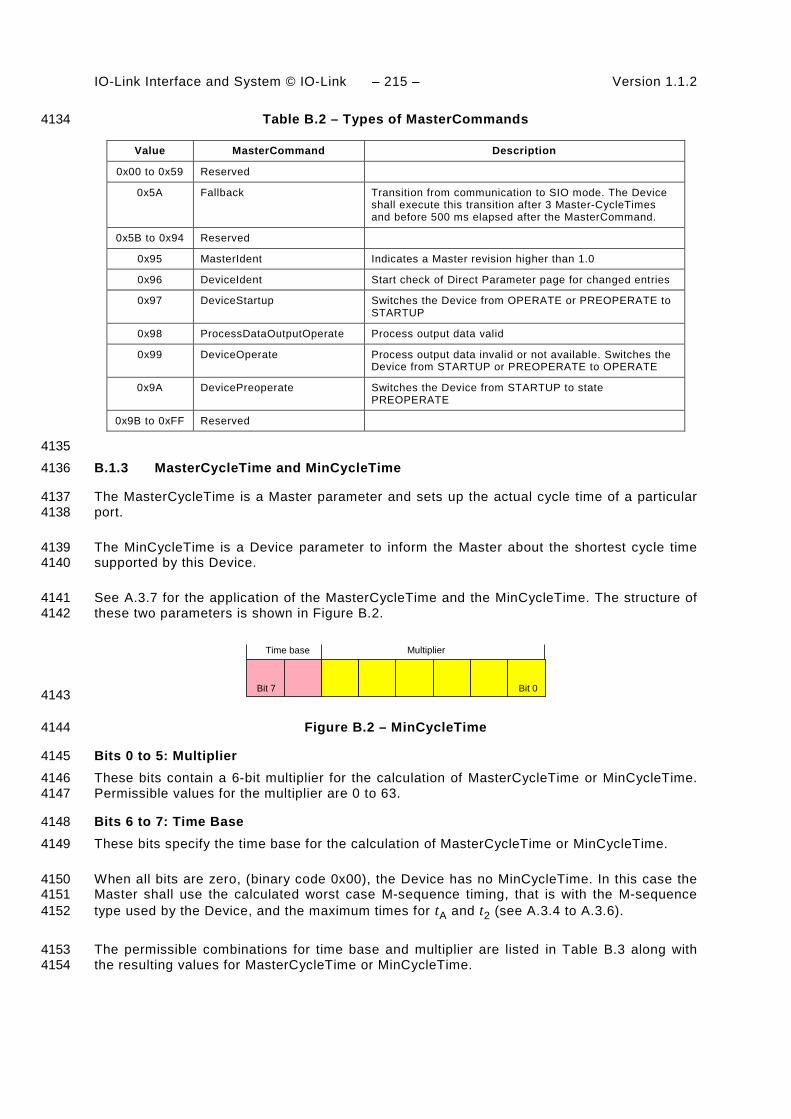
IO-Link Interface and System © IO-Link – 215 – Version 1.1.2
Table B.2 – Types of MasterCommands 4134
Value MasterCommand Description
0x00 to 0x59 Reserved
0x5A Fallback Transition from communication to SIO mode. The Device shall execute this transition after 3 Master-CycleTimes and before 500 ms elapsed after the MasterCommand.
0x5B to 0x94 Reserved
0x95 MasterIdent Indicates a Master revision higher than 1.0
0x96 DeviceIdent Start check of Direct Parameter page for changed entries
0x97 DeviceStartup Switches the Device from OPERATE or PREOPERATE to STARTUP
0x98 ProcessDataOutputOperate Process output data valid
0x99 DeviceOperate Process output data invalid or not available. Switches the Device from STARTUP or PREOPERATE to OPERATE
0x9A DevicePreoperate Switches the Device from STARTUP to state PREOPERATE
0x9B to 0xFF Reserved
4135 B.1.3 MasterCycleTime and MinCycleTime 4136
The MasterCycleTime is a Master parameter and sets up the actual cycle time of a particular 4137 port. 4138
The MinCycleTime is a Device parameter to inform the Master about the shortest cycle time 4139 supported by this Device. 4140
See A.3.7 for the application of the MasterCycleTime and the MinCycleTime. The structure of 4141 these two parameters is shown in Figure B.2. 4142
Time base Multiplier
Bit 0Bit 7 4143
Figure B.2 – MinCycleTime 4144
Bits 0 to 5: Multiplier 4145 These bits contain a 6-bit multiplier for the calculation of MasterCycleTime or MinCycleTime. 4146 Permissible values for the multiplier are 0 to 63. 4147
Bits 6 to 7: Time Base 4148
These bits specify the time base for the calculation of MasterCycleTime or MinCycleTime. 4149
When all bits are zero, (binary code 0x00), the Device has no MinCycleTime. In this case the 4150 Master shall use the calculated worst case M-sequence timing, that is with the M-sequence 4151 type used by the Device, and the maximum times for tA and t2 (see A.3.4 to A.3.6). 4152
The permissible combinations for time base and multiplier are listed in Table B.3 along with 4153 the resulting values for MasterCycleTime or MinCycleTime. 4154

Version 1.1.2 – 216 – IO-Link Interface and System © IO-Link
Table B.3 – Possible values of MasterCycleTime and MinCycleTime 4155
Time base encoding
Time Base value Calculation Cycle Time
00 0,1 ms Multiplier × Time Base 0,4 ms to 6,3 ms
01 0,4 ms 6,4 ms + Multiplier × Time Base
6,4 ms to 31,6 ms
10 1,6 ms 32,0 ms + Multiplier × Time Base
32,0 ms to 132,8 ms
11 Reserved Reserved Reserved
NOTE The value 0,4 results from the minimum possible transmission time according to A.3.7.
4156 B.1.4 M-sequence Capability 4157
The structure of the M-sequence Capability parameter is shown in Figure B.3. 4158
Reserved ISDU
PREOPERATEM-sequence
typeOPERATE
M-sequence type
Bit 0Bit 7 4159
Figure B.3 – M-sequence Capability 4160
Bit 0: ISDU 4161 This bit indicates whether or not the ISDU communication channel is supported. Permissible 4162 values for ISDU are listed in Table B.4. 4163
Table B.4 – Values of ISDU 4164
Value Definition
0 ISDU not supported
1 ISDU supported
4165 Bits 1 to 3: Coding of the OPERATE M-sequence type 4166 This parameter indicates the available M-sequence type during the OPERATE state. 4167 Permissible codes for the OPERATE M-sequence type are listed in Table A.9 for legacy 4168 Devices and in Table A.10 for Devices according to this standard. 4169
Bits 4 to 5: Coding of the PREOPERATE M-sequence type 4170
This parameter indicates the available M-sequence type during the PREOPERATE state. 4171 Permissible codes for the PREOPERATE M-sequence type are listed in Table A.8. 4172
Bits 6 to 7: Reserved 4173
These bits are reserved and shall be set to zero in this version of the specification. 4174
B.1.5 RevisionID (RID) 4175
The RevisionID parameter is the two-digit version number of the SDCI protocol currently used 4176 within the Device. Its structure is shown in Figure B.4. The initial value of RevisionID at 4177 powerup is the inherent value for protocol RevisionID. It can be overwritten (see 10.6.3) until 4178 the next powerup. 4179
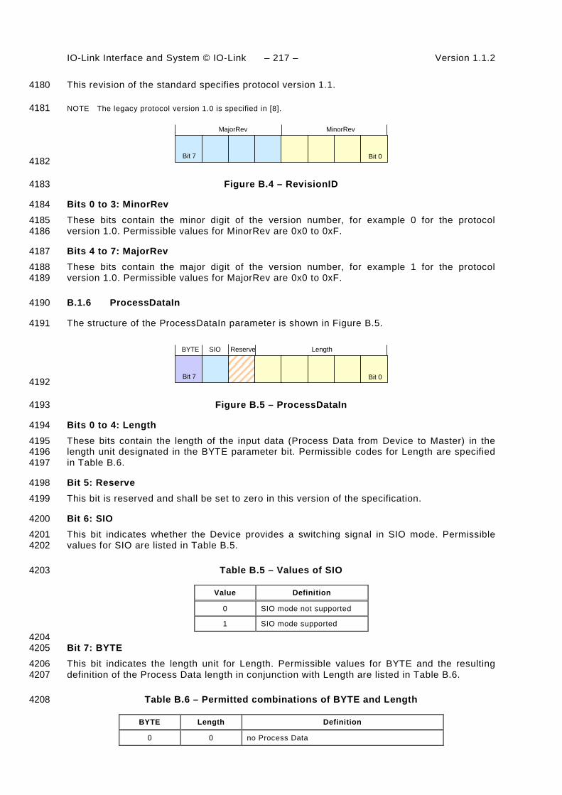
IO-Link Interface and System © IO-Link – 217 – Version 1.1.2
This revision of the standard specifies protocol version 1.1. 4180
NOTE The legacy protocol version 1.0 is specified in [8]. 4181
MinorRevMajorRev
Bit 0Bit 7 4182
Figure B.4 – RevisionID 4183
Bits 0 to 3: MinorRev 4184
These bits contain the minor digit of the version number, for example 0 for the protocol 4185 version 1.0. Permissible values for MinorRev are 0x0 to 0xF. 4186
Bits 4 to 7: MajorRev 4187
These bits contain the major digit of the version number, for example 1 for the protocol 4188 version 1.0. Permissible values for MajorRev are 0x0 to 0xF. 4189
B.1.6 ProcessDataIn 4190
The structure of the ProcessDataIn parameter is shown in Figure B.5. 4191
LengthReserveSIOBYTE
Bit 0Bit 7 4192
Figure B.5 – ProcessDataIn 4193
Bits 0 to 4: Length 4194
These bits contain the length of the input data (Process Data from Device to Master) in the 4195 length unit designated in the BYTE parameter bit. Permissible codes for Length are specified 4196 in Table B.6. 4197
Bit 5: Reserve 4198
This bit is reserved and shall be set to zero in this version of the specification. 4199
Bit 6: SIO 4200
This bit indicates whether the Device provides a switching signal in SIO mode. Permissible 4201 values for SIO are listed in Table B.5. 4202
Table B.5 – Values of SIO 4203
Value Definition
0 SIO mode not supported
1 SIO mode supported
4204 Bit 7: BYTE 4205
This bit indicates the length unit for Length. Permissible values for BYTE and the resulting 4206 definition of the Process Data length in conjunction with Length are listed in Table B.6. 4207
Table B.6 – Permitted combinations of BYTE and Length 4208
BYTE Length Definition
0 0 no Process Data

Version 1.1.2 – 218 – IO-Link Interface and System © IO-Link
BYTE Length Definition
0 1 1 bit Process Data, structured in bits
0 n (2-15) n bit Process Data, structured in bits
0 16 16 bit Process Data, structured in bits
0 17 to 31 Reserved
1 0, 1 Reserved
1 2 3 octets Process Data, structured in octets
1 n (3-30) n+1 octets Process Data, structured in octets
1 31 32 octets Process Data, structured in octets
4209 B.1.7 ProcessDataOut 4210
The structure of the ProcessDataOut parameter is the same as with ProcessDataIn, except 4211 with bit 6 ("SIO") reserved. 4212
B.1.8 VendorID (VID) 4213
These octets contain a worldwide unique value per vendor. 4214
NOTE VendorIDs are assigned by the IO-Link community. 4215
B.1.9 DeviceID (DID) 4216
These octets contain the currently used DeviceID. A value of "0" is not permitted. The initial 4217 value of DeviceID at powerup is the inherent value of DeviceID. It can be overwritten (see 4218 10.6.2) until the next powerup. 4219
NOTE The communication parameters MinCycleTime, M-sequence Capability, Process Data In and Process Data 4220 Out can be changed to achieve compatibility to the requested DeviceID. 4221
B.1.10 FunctionID (FID) 4222
This parameter will be defined in a later version. 4223
B.1.11 SystemCommand 4224
Only Devices without ISDU support shall use the parameter SystemCommand in the Direct 4225 Parameter page 1. The implementation of SystemCommand is optional. See Table B.9 for a 4226 detailed description of the SystemCommand functions. 4227
NOTE The SystemCommand on the Direct Parameter page 1 does not provide a positive or negative response 4228 upon execution of a selected function 4229
B.1.12 Device specific Direct Parameter page 2 4230
The Device specific Direct Parameters are a set of parameters available to the Device specific 4231 technology. The implementation of Device specific Direct Parameters is optional. 4232
NOTE The complete parameter list of the Direct Parameter page 2 is read or write accessible via index 1 (see 4233 B.1.1). 4234
B.2 Predefined Device parameters 4235
B.2.1 Overview 4236
The many different technologies and designs of sensors and actuators require individual and 4237 easy access to complex parameters and commands beyond the capabilities of the Direct 4238

IO-Link Interface and System © IO-Link – 219 – Version 1.1.2
Parameter page 2. From a Master's point of view, these complex parameters and commands 4239 are called application data objects. So-called ISDU "containers" are the transfer means to 4240 exchange application data objects or short data objects. The index of the ISDU is used to 4241 address the data objects. Figure B.6 shows the general mapping of data objects for the ISDU 4242 transmission. 4243
System0x02 … 0x0F
Identification0x10 … 0x1F
Diagnosis0x20 … 0x2F
Preferred Index0x40 … 0xFE
Parameter via ISDU
Device para-meters(individual orprofile)
Predefinedparameters
Profile specific parameter0x30 … 0x3F
Extended Index0x0100 … 0x3FFF
Reserved0x5000 … 0xFFFF
Profile specific Index0x4000 … 0x4FFF
4244
Figure B.6 – Index space for ISDU data objects 4245
Subclause B.2 contains definitions and requirements for the implementation of technology 4246 specific Device applications. Implementation rules for parameters and commands are 4247 specified in Table B.7. 4248
Table B.7 – Implementation rules for parameters and commands 4249
Rule number Rule specification
1 All parameters of an Index shall be readable and/or writeable as an entire data object via Subindex 0
2 The technology specific device application shall resolve inconsistencies of dependent parameter sets during parameterization
3 The duration of an ISDU service request is limited (see Table 97). A master application can abort ISDU services after this timeout
4 Application commands (for example teach-in, reset to factory settings, etc.) are treated like parameters. The initiated execution of an application command is confirmed with a positive service response – Write.res(+). A negative service response – Write.res(-) – shall indicate that the execution of the application command failed. In both cases the timeout limit shall be considered (see Table 97)
4250 Table B.8 specifies the assignment of data objects (parameters and commands) to the Index 4251 range of ISDUs. All indices above 2 are ISDU related. 4252
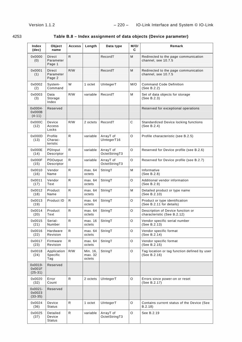
Version 1.1.2 – 220 – IO-Link Interface and System © IO-Link
Table B.8 – Index assignment of data objects (Device parameter) 4253
Index (dec)
Object name
Access Length Data type M/O/C
Remark
0x0000 (0)
Direct Parameter Page 1
R RecordT M Redirected to the page communication channel, see 10.7.5
0x0001 (1)
Direct Parameter Page 2
R/W RecordT M Redirected to the page communication channel, see 10.7.5
0x0002 (2)
System-Command
W 1 octet UIntegerT M/O Command Code Definition (See B.2.2)
0x0003 (3)
Data Storage Index
R/W variable RecordT M Set of data objects for storage (See B.2.3)
0x0004- 0x000B (4-11)
Reserved Reserved for exceptional operations
0x000C (12)
Device Access Locks
R/W 2 octets RecordT C Standardized Device locking functions (See B.2.4)
0x000D (13)
Profile Charac-teristic
R variable ArrayT of UIntegerT16
O Profile characteristic (see B.2.5)
0x000E (14)
PDInput Descriptor
R variable ArrayT of OctetStringT3
O Reserved for Device profile (see B.2.6)
0x000F (15)
PDOutput Descriptor
R variable ArrayT of OctetStringT3
O Reserved for Device profile (see B.2.7)
0x0010 (16)
Vendor Name
R max. 64 octets
StringT M Informative (See B.2.8)
0x0011 (17)
Vendor Text
R max. 64 octets
StringT O Additional vendor information (See B.2.9)
0x0012 (18)
Product Name
R max. 64 octets
StringT M Detailed product or type name (See B.2.10)
0x0013 (19)
Product ID R max. 64 octets
StringT O Product or type identification (See B.2.11 for details)
0x0014 (20)
Product Text
R max. 64 octets
StringT O Description of Device function or characteristic (See B.2.12)
0x0015 (21)
Serial- Number
R max. 16 octets
StringT O Vendor specific serial number (See B.2.13)
0x0016 (22)
Hardware Revision
R max. 64 octets
StringT O Vendor specific format (See B.2.14)
0x0017 (23)
Firmware Revision
R max. 64 octets
StringT O Vendor specific format (See B.2.15)
0x0018 (24)
Application Specific Tag
R/W Min. 16, max. 32 octets
StringT O Tag location or tag function defined by user (See B.2.16)
0x0019- 0x001F (25-31)
Reserved
0x0020 (32)
Error Count
R 2 octets UIntegerT O Errors since power-on or reset (See B.2.17)
0x0021- 0x0023 (33-35)
Reserved
0x0024 (36)
Device Status
R 1 octet UIntegerT O Contains current status of the Device (See B.2.18)
0x0025 (37)
Detailed Device Status
R variable ArrayT of OctetStringT3
O See B.2.19
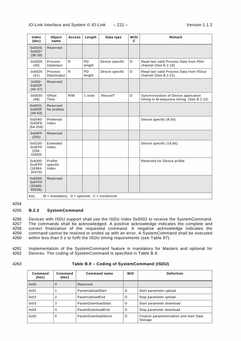
IO-Link Interface and System © IO-Link – 221 – Version 1.1.2
Index (dec)
Object name
Access Length Data type M/O/C
Remark
0x0026- 0x0027 (38-39)
Reserved
0x0028 (40)
Process- DataInput
R PD length
Device specific O Read last valid Process Data from PDin channel (See B.2.19)
0x0029 (41)
Process- DataOutput
R PD length
Device specific O Read last valid Process Data from PDout channel (See B.2.21)
0x002- 0x002F (42-47)
Reserved
0x0030 (48)
Offset Time
R/W 1 octet RecordT O Synchronization of Device application timing to M-sequence timing (See B.2.22)
0x0031- 0x003F (49-63)
Reserved for profiles
0x0040-0x00FE (64-254)
Preferred Index
Device specific (8 bit)
0x00FF (255)
Reserved
0x0100-0x3FFF
(256-16383)
Extended Index
Device specific (16 bit)
0x4000-0x4FFF (16384-20479)
Profile specific Index
Reserved for Device profile
0x5000-0xFFFF (20480-65535)
Reserved
Key M = mandatory; O = optional; C = conditional
4254 B.2.2 SystemCommand 4255
Devices with ISDU support shall use the ISDU Index 0x0002 to receive the SystemCommand. 4256 The commands shall be acknowledged. A positive acknowledge indicates the complete and 4257 correct finalization of the requested command. A negative acknowledge indicates the 4258 command cannot be realized or ended up with an error. A SystemCommand shall be executed 4259 within less than 5 s to fulfil the ISDU timing requirements (see Table 97). 4260
Implementation of the SystemCommand feature is mandatory for Masters and optional for 4261 Devices. The coding of SystemCommand is specified in Table B.9. 4262
Table B.9 – Coding of SystemCommand (ISDU) 4263
Command (hex)
Command (dec)
Command name M/O Definition
0x00 0 Reserved
0x01 1 ParamUploadStart O Start parameter upload
0x02 2 ParamUploadEnd O Stop parameter upload
0x03 3 ParamDownloadStart O Start parameter download
0x04 4 ParamDownloadEnd O Stop parameter download
0x05 5 ParamDownloadStore O Finalize parameterization and start Data Storage

Version 1.1.2 – 222 – IO-Link Interface and System © IO-Link
Command (hex)
Command (dec)
Command name M/O Definition
0x06 6 ParamBreak O Cancel all Param commands
0x07 to 0x3F 7 to 63 Reserved
0x40 to 0x7F 64 to 127 Reserved for profiles
0x80 128 Device reset O
0x81 129 Application reset O
0x82 130 Restore factory settings O
0x83 to 0x9F 131 to 159 Reserved
0xA0 to 0xFF 160 to 255 Vendor specific
NOTE See 10.3
Key M = mandatory; O = optional
4264 The SystemCommand 0x05 (ParamDownloadStore) shall be implemented according to 10.4.2, 4265 whenever the Device provides parameters to be stored via the Data Storage mechanism, i.e. 4266 parameter "Index_List" in Index 0x0003 is not empty (see Table B.10). 4267
The implementation of the SystemCommands 0x01 to 0x06 required for block parameteri-4268 zation according to 10.3.5 is optional. However, all of these commands or none of them shall 4269 be implemented (for SystemCommand 0x05 the rule for Data Storage dominates). 4270
See B.1.11 for SystemCommand options on the Direct Parameter page 1. 4271
B.2.3 Data Storage Index 4272
Table B.10 specifies the Data Storage Index assignments. 4273
Table B.10 – Data Storage Index assignments 4274
Index Subindex Access Parameter Name
Coding Data type
0x0003 01 R/W DS_Command 0x00: Reserved 0x01: DS_UploadStart 0x02: DS_UploadEnd 0x03: DS_DownloadStart 0x04: DS_DownloadEnd 0x05: DS_Break 0x06 to 0xFF: Reserved
UIntegerT8 (8 bit)
02 R State_Property Bit 0: Reserved Bit 1 and 2: State of Data Storage 0b00: Inactive 0b01: Upload 0b10: Download 0b11: Data Storage locked Bit 3 to 6: Reserved Bit 7: DS_UPLOAD_FLAG "1": DS_UPLOAD_REQ pending "0": no DS_UPLOAD_REQ
UIntegerT8 (8 bit)
03 R Data_Storage_ Size
Number of octets for storing all the necessary information for the Device replacement (see 10.4.5). Maximum size is 2 048 octets.
UIntegerT32 (32 bit)
04 R Parameter_ Checksum
Parameter set revision indication: CRC signature or Revision Counter (see 10.4.8)
UIntegerT32 (32 bit)
05 R Index_List List of parameter indices to be saved (see Table B.11)
OctetStringT (variable)

IO-Link Interface and System © IO-Link – 223 – Version 1.1.2
The parameter Data Storage Index 0x0003 contains all the information to be used for the Data 4275 Storage handling. This parameter is reserved for private exchanges between the Master and 4276 the Device; the Master shall block any access request from a gateway application to this 4277 Index (see Figure 4). The parameters within this Index 0x0003 are specified as follows. 4278
DS_Command 4279
This octet carries the Data Storage commands for the Device. 4280
State_Property 4281
This octet indicates the current status of the Data Storage mechanism. Bit 7 shall be stored in 4282 non-volatile memory. The Master checks this bit at start-up and performs a parameter upload 4283 if requested. 4284
Data_Storage_Size 4285
These four octets provide the requested memory size as number of octets for storing all the 4286 information required for the replacement of a Device including the structural information 4287 (Index, Subindex). Data type is UIntegerT32 (32 bit). The maximum size is 2 048 octets. See 4288 Table F.1 for the elements to be taken into account in the size calculation. 4289
Parameter_Checksum 4290
This checksum is used to detect changes in the parameter set without reading all parameters. 4291 The value of the checksum is calculated according to the procedure in 10.4.8. The Device 4292 shall change the checksum whenever a parameter out of the parameter set has been altered. 4293 Different parameter sets shall hold different checksums. It is recommended that the Device 4294 stores this parameter locally in non-volatile memory. 4295
Index_List 4296
Table B.11 specifies the structure of the Index_List. Each Index_List can carry up to 70 4297 entries (see Table 97). 4298
Table B.11 – Structure of Index_List 4299
Entry Address Definition Data type
X1 Index Index of first parameter to be saved Unsigned16
Subindex Subindex of first parameter to be saved Unsigned8
X2 Index Index of next parameter to be saved Unsigned16
Subindex Subindex of next parameter to be saved Unsigned8
….. ……… ………………………………………. ………..
Xn Index Index of last parameter to be saved Unsigned16
Subindex Subindex of last parameter to be saved Unsigned8
Xn+1 Index Termination_Marker 0x0000: End of Index_List >0x0000: Next Index containing an Index_List
Unsigned16
4300 Large sets of parameters can be handled via concatenated Index_Lists. The last two octets of 4301 the Index_List shall carry the Termination Marker. A value "0" indicates the end of the Index 4302 List. In case of concatenation the Termination Marker is set to the next Index containing an 4303 Index List. The structure of the following Index List is the same as specified in Table B.11. 4304 Thus, the concatenation of lists ends if a Termination Marker with the value "0" is found. 4305
B.2.4 Device Access Locks 4306
The parameter Device Access Locks allows control of the Device behaviour. Standardized 4307 Device functions can independently be configured via defined flags in this parameter. The 4308 Device Access Locks configuration can be changed by overwriting the parameter. The actual 4309

Version 1.1.2 – 224 – IO-Link Interface and System © IO-Link
configuration setting is available per read access to this parameter. The data type is RecordT 4310 of BooleanT. Access is only permitted via Subindex 0. This parameter is optional. If 4311 implemented it shall be non-volatile. 4312
The following Device access lock categories are specified. 4313
• Parameter write access (optional) 4314
• Data Storage (mandatory if the Device supports Data Storage) 4315
• Local parameterization (optional) 4316
• Local user interface operation (optional) 4317
Table B.12 lists the Device locking possibilities. 4318
Table B.12 – Device locking possibilities 4319
Bit Category Definition
0 Parameter (write) access (optional) 0: unlocked (default) 1: locked
1 Data Storage (mandatory if the Device supports Data Storage)
0: unlocked (default) 1: locked (see NOTE)
2 Local parameterization (optional) 0: unlocked (default) 1: locked
3 Local user interface (optional) 0: unlocked (default) 1: locked
4 – 15 Reserved
NOTE The Master reads the parameter State_Property/State of Data Storage (see Table B.10) prior to any actions
4320 Parameter (write) access: 4321
If this bit is set, write access to all Device parameters over the SDCI communication interface 4322 is inhibited for all read/write parameters of the Device except the parameter Device Access 4323 Locks. Read access is not affected. The Device shall respond with the negative service 4324 response – access denied – to a write access, if the parameter access is locked. 4325
The parameter (write) access lock mechanism shall not block downloads of the Data Storage 4326 mechanism (between DS_DownloadStart and DS_DownloadEnd or DS_Break). 4327
Data Storage: 4328 If this bit is set in the Device, the Data Storage mechanism is disabled (see 10.4.2 and 4329 11.3.3). In this case, the Device shall respond to a write access (within its Data Storage 4330 Index) with a negative service response – access denied – (see B.2.3). Read access to its 4331 Data Storage Index is not affected. 4332
This setting is also indicated in the State Property within Data Storage Index. 4333
Local parameterization: 4334 If this bit is set, the parameterization via local control elements on the Device is inhibited. 4335
Local user interface: 4336
If this bit is set, operation of the human machine interface on the Device is disabled. 4337
B.2.5 Profile Characteristic 4338
This parameter contains the list of ProfileIdentifiers (PID's) corresponding to the Device 4339 Profile implemented in the Device. 4340

IO-Link Interface and System © IO-Link – 225 – Version 1.1.2
NOTE Details are provided in [7]. 4341
B.2.6 PD Input Descriptor 4342
This parameter contains the description of the data structure of the process input data for a 4343 profile Device. 4344
NOTE Details are provided in [7]. 4345
B.2.7 PD Output Descriptor 4346
This parameter contains the description of the data structure of the process output data for a 4347 profile Device. 4348
NOTE Details are provided in [7]. 4349
B.2.8 Vendor Name 4350
The parameter Vendor Name contains only one of the vendor names listed for the assigned 4351 VendorID. The parameter is a read-only data object. The data type is StringT with a maximum 4352 fixedLength of 64. This parameter is mandatory. 4353
NOTE The list of vendor names associated with a given VendorID is maintained by the IO-Link community. 4354
B.2.9 Vendor Text 4355
The parameter Vendor Text contains additional information about the vendor. The parameter 4356 is a read-only data object. The data type is StringT with a maximum fixedLength of 64. This 4357 parameter is optional. 4358
B.2.10 Product Name 4359
The parameter Product Name contains the complete product name. The parameter is a read-4360 only data object. The data type is StringT with a maximum fixedLength of 64. This parameter 4361 is mandatory. 4362
NOTE The corresponding entry in the IODD Device variant list is expected to match this parameter. 4363
B.2.11 Product ID 4364
The parameter Product ID shall contain the vendor specific product or type identification of 4365 the Device. The parameter is a read-only data object. The data type is StringT with a 4366 maximum fixedLength of 64. This parameter is optional. 4367
B.2.12 Product Text 4368
The parameter Product Text shall contain additional product information for the Device, such 4369 as product category (for example Photoelectric Background Suppression, Ultrasonic Distance 4370 Sensor, Pressure Sensor, etc.). The parameter is a read-only data object. The data type is 4371 StringT with a maximum fixedLength of 64. This parameter is optional. 4372
B.2.13 SerialNumber 4373
The parameter SerialNumber shall contain a unique vendor specific code for each individual 4374 Device. The parameter is a read-only data object. The data type is StringT with a maximum 4375 fixedLength of 16. This parameter is optional. 4376
B.2.14 Hardware Revision 4377
The parameter Hardware Revision shall contain a vendor specific coding for the hardware 4378 revision of the Device. The parameter is a read-only data object. The data type is StringT with 4379 a maximum fixedLength of 64. This parameter is optional. 4380

Version 1.1.2 – 226 – IO-Link Interface and System © IO-Link
B.2.15 Firmware Revision 4381
The parameter Firmware Revision shall contain a vendor specific coding for the firmware 4382 revision of the Device. The parameter is a read-only data object. The data type is StringT with 4383 a maximum fixedLength of 64. This parameter is optional. 4384
B.2.16 Application Specific Tag 4385
The parameter Application Specific Tag shall be provided as read/write data object for the 4386 user application. It can serve as a "tag function" (role of the Device) or a "tag location" 4387 (location of the Device). The data type is StringT with a minimum fixedLength of 16 and a 4388 maximum fixedLength of 32. As default it is recommended to fill this parameter with "***". This 4389 parameter is optional. 4390
NOTE In process automation usually this length is 32 octets. 4391
B.2.17 Error Count 4392
The parameter Error Count provides information on errors occurred in the Device application 4393 since power-on or reset. Usage of this parameter is vendor or Device specific. The data type 4394 is UIntegerT with a bitLength of 16. The parameter is a read-only data object. This parameter 4395 is optional. 4396
B.2.18 Device Status 4397
B.2.18.1 Overview 4398
The parameter Device Status shall provide information about the Device condition (diagnosis) 4399 by the Device's technology. The data type is UIntegerT with a bitLength of 8. The parameter 4400 is a read-only data object. This parameter is optional. 4401
The following Device conditions in Table B.13 are specified. They shall be generated by the 4402 Device applications. The parameter Device Status can be read by any PLC program or tools 4403 such as Asset Management (see Clause 11). 4404
Table B.13 lists the different Device Status information. The criteria for these indications are 4405 specified in subclauses B.2.18.2 through B.2.18.5. 4406
Table B.13 – Device status parameter 4407
Value Definition
0 Device is operating properly
1 Maintenance-Required (see B.2.18.2)
2 Out-of-Specification (see B.2.18.3)
3 Functional-Check (see B.2.18.4)
4 Failure (see B.2.18.5)
5 – 255 Reserved
4408 B.2.18.2 Maintenance-required 4409
Although the Process Data are valid, internal diagnostics indicate that the Device is close to 4410 loose its ability of correct functioning. 4411
EXAMPLES Optical lenses getting dusty, build-up of deposits, lubricant level low. 4412

IO-Link Interface and System © IO-Link – 227 – Version 1.1.2
B.2.18.3 Out-of-Specification 4413
Although the Process Data are valid, internal diagnostics indicate that the Device is operating 4414 outside its specified measuring range or environmental conditions. 4415
EXAMPLES Power supply, auxiliary energy, temperature, pneumatic pressure, magnetic interference, vibrations, 4416 acceleration, interfering light, bubble formation in liquids. 4417
B.2.18.4 Functional-Check 4418
Process Data are temporarily invalid due to intended manipulations on the Device. 4419
EXAMPLES Calibrations, teach-in, position adjustments, simulation. 4420
B.2.18.5 Failure 4421
Process Data invalid due to malfunction in the Device or its peripherals. The Device is unable 4422 to perform its intended function. 4423
B.2.19 Detailed Device Status 4424
The parameter Detailed Device Status shall provide information about currently pending 4425 Events in the Device. Events of TYPE "Error" or "Warning" and MODE "Event appears" (see 4426 A.6.4) shall be entered into the list of Detailed Device Status with EventQualifier and 4427 EventCode. Upon occurrence of an Event with MODE "Event disappears", the corresponding 4428 entry in Detailed Device Status shall be set to EventQualifier "0x00" and EventCode "0x0000". 4429 This way this parameter always provides the current diagnosis status of the Device. The 4430 parameter is a read-only data object. The data type is ArrayT with a maximum number of 64 4431 array elements (Event entries). The number of array elements of this parameter is Device 4432 specific. Upon power-off or reset of the Device the contents of all array elements is set to 4433 initial settings – EventQualifier "0x00", EventCode "0x0000". This parameter is optional. 4434
Table B.14 specifies the structure of the parameter Detailed Device Status. 4435
Table B.14 – Detailed Device Status (Index 0x0025) 4436
Sub-index
Object name Data Type Comment
1 Error_Warning_1 3 octets All octets 0x00: no Error/ Warning Octet 1: EventQualifier Octet 2,3: EventCode
2 Error_Warning_2 3 octets
3 Error_Warning_3 3 octets
4 Error_Warning_4 3 octets
…
n Error_Warning_n 3 octets
4437 The designer may choose the implementation of a static list, i.e. one fix array position for 4438 each Event with a specific EventCode, or a dynamic list, i.e. each Event entry is stored into 4439 the next free array position. Subindex access is not permitted for a dynamic list. 4440
B.2.20 ProcessDataInput 4441
The parameter ProcessDataInput shall provide the last valid process input data from the 4442 Device application. The data type and structure is identical to the Process Data In transferred 4443 in the process communication channel. The parameter is a read-only data object. This 4444 parameter is optional. 4445

Version 1.1.2 – 228 – IO-Link Interface and System © IO-Link
B.2.21 ProcessDataOutput 4446
The parameter ProcessDataOutput shall provide the last valid process output data written to 4447 the Device application. The data type and structure is identical to the Process Data Out 4448 transferred in the process communication channel. The parameter is a read-only data object. 4449 This parameter is optional. 4450
B.2.22 Offset Time 4451
The parameter Offset Time allows a Device application to synchronize on M-sequence cycles 4452 of the data link layer via adjustable offset times. The data type is RecordT. Access is only 4453 possible via Subindex 0. The parameter is a read/write data object. This parameter is 4454 optional. 4455
The structure of the parameter Offset Time is shown in Figure B.7: 4456
Time base Multiplier
Bit 0Bit 7 4457
Figure B.7 – Structure of the Offset Time 4458
Bits 0 to 5: Multiplier 4459
These bits contain a 6-bit factor for the calculation of the Offset Time. Permissible values for 4460 the multiplier are 0 to 63. 4461
Bits 6 to 7: Time Base 4462
These bits contain the time base for the calculation of the Offset Time. 4463
The permissible combinations for Time Base and Multiplier are listed in Table B.15 along with 4464 the resulting values for Offset Time. Setting both Multiplier and Time Base to zero deactivates 4465 synchronization with the help of an Offset Time. The value of Offset Time shall not exceed the 4466 MasterCycleTime (see B.1.3) 4467
Table B.15 – Time base coding and values of Offset Time 4468
Time base encoding
Time Base value Calculation Offset Time
00 0,01 ms Multiplier × Time Base 0,01 ms to 0,63 ms
01 0,04 ms 0,64 ms + Multiplier × Time Base
0,64 ms to 3,16 ms
10 0,64 ms 3,20 ms + Multiplier × Time Base
3,20 ms to 43,52 ms
11 2,56 ms 44,16 ms + Multiplier × Time Base
44,16 ms to 126,08 ms
4469 B.2.23 Profile Parameter (reserved) 4470
Indices 0x0031 to 0x003F are reserved for Device profiles. 4471
NOTE Details are provided in [7]. 4472
B.2.24 Preferred Index 4473
Preferred Indices (0x0040 to 0x00FE) can be used for vendor specific Device functions. This 4474 range of indices is considered preferred due to lower protocol overhead within the ISDU and 4475
IO-Link Interface and System © IO-Link – 229 – Version 1.1.2
thus higher data throughput for small data objects as compared to the Extended Index (see 4476 B.2.25). 4477
B.2.25 Extended Index 4478
Extended Indices (0x0100 to 0x3FFF) can be used for vendor specific Device functions. 4479
B.2.26 Profile specific Index (reserved) 4480
Indices 0x4000 to 0x4FFF are reserved for Device profiles. 4481
NOTE Details are provided in [7]. 4482

Version 1.1.2 – 230 – IO-Link Interface and System © IO-Link
Annex C 4483 (normative) 4484
4485 ErrorTypes (ISDU errors) 4486
C.1 General 4487
An ErrorType is used within negative service confirmations of ISDUs (see A.5.2 and Table 4488 A.13). It indicates the cause of a negative confirmation of a Read or Write service. The origin 4489 of the error may be located in the Master (local) or in the Device (remote). 4490
The ErrorType consists of two octets, the main error cause and more specific information: 4491
• ErrorCode (high order octet) 4492
• AdditionalCode (low order octet) 4493
The ErrorType represents information about the incident, the origin and the instance. The 4494 permissible ErrorTypes and the criteria for their deployment are listed in C.2 and C.3. All 4495 other ErrorType values are reserved and shall not be used. 4496
C.2 Application related ErrorTypes 4497
C.2.1 Overview 4498
The permissible ErrorTypes resulting from the Device application are listed in Table C.1. 4499
Table C.1 – ErrorTypes 4500
Incident Error Code
Additional Code
Name Definition
Device application error – no details
0x80 0x00 APP_DEV See C.2.2
Index not available
0x80 0x11 IDX_NOTAVAIL See C.2.3
Subindex not available
0x80 0x12 SUBIDX_NOTAVAIL See C.2.4
Service temporarily not available
0x80 0x20 SERV_NOTAVAIL See C.2.5
Service temporarily not available – local control
0x80 0x21 SERV_NOTAVAIL_LOCCTRL See C.2.6
Service temporarily not available – Device control
0x80 0x22 SERV_NOTAVAIL_DEVCTRL See C.2.7
Access denied 0x80 0x23 IDX_NOT_WRITEABLE See C.2.8
Parameter value out of range
0x80 0x30 PAR_VALOUTOFRNG See C.2.9
Parameter value above limit
0x80 0x31 PAR_VALGTLIM See C.2.10
Parameter value below limit
0x80 0x32 PAR_VALLTLIM See C.2.11
Parameter length overrun
0x80 0x33 VAL_LENOVRRUN See C.2.12

IO-Link Interface and System © IO-Link – 231 – Version 1.1.2
Incident Error Code
Additional Code
Name Definition
Parameter length underrun
0x80 0x34 VAL_LENUNDRUN See C.2.13
Function not available
0x80 0x35 FUNC_NOTAVAIL See C.2.14
Function temporarily unavailable
0x80 0x36 FUNC_UNAVAILTEMP See C.2.15
Invalid parameter set
0x80 0x40 PAR_SETINVALID See C.2.16
Inconsistent parameter set
0x80 0x41 PAR_SETINCONSIST See C.2.17
Application not ready
0x80 0x82 APP_DEVNOTRDY See C.2.18
Vendor specific 0x81 0x00 UNSPECIFIC See C.2.19
Vendor specific 0x81 0x01 to 0xFF VENDOR_SPECIFIC See C.2.19
4501 C.2.2 Device application error – no details 4502
This ErrorType shall be used if the requested service has been refused by the Device 4503 application and no detailed information of the incident is available. 4504
C.2.3 Index not available 4505
This ErrorType shall be used whenever a read or write access occurs to a not existing Index. 4506
C.2.4 Subindex not available 4507
This ErrorType shall be used whenever a read or write access occurs to a not existing 4508 Subindex. 4509
C.2.5 Service temporarily not available 4510
This ErrorType shall be used if a parameter is not accessible for a read or write service due to 4511 the current state of the Device application. 4512
C.2.6 Service temporarily not available – local control 4513
This ErrorType shall be used if a parameter is not accessible for a read or write service due to 4514 an ongoing local operation at the Device (for example operation or parameterization via an 4515 on-board Device control panel). 4516
C.2.7 Service temporarily not available – device control 4517
This ErrorType shall be used if a read or write service is not accessible due to a remote 4518 triggered state of the device application (for example parameterization during a remote 4519 triggered teach-in operation or calibration). 4520
C.2.8 Access denied 4521
This ErrorType shall be used if a write service tries to access a read-only parameter. 4522
C.2.9 Parameter value out of range 4523
This ErrorType shall be used for a write service to a parameter outside its permitted range of 4524 values. 4525

Version 1.1.2 – 232 – IO-Link Interface and System © IO-Link
C.2.10 Parameter value above limit 4526
This ErrorType shall be used for a write service to a parameter above its specified value 4527 range. 4528
C.2.11 Parameter value below limit 4529
This ErrorType shall be used for a write service to a parameter below its specified value 4530 range. 4531
C.2.12 Parameter length overrun 4532
This ErrorType shall be used when the content of a write service to a parameter is greater 4533 than the parameter specified length. This ErrorType shall also be used, if a data object is too 4534 large to be processed by the Device application (for example ISDU buffer restriction). 4535
C.2.13 Parameter length underrun 4536
This ErrorType shall be used when the content of a write service to a parameter is less than 4537 the parameter specified length (for example write access of an Unsigned16 value to an 4538 Unsigned32 parameter). 4539
C.2.14 Function not available 4540
This ErrorType shall be used for a write service with a command value not supported by the 4541 Device application (for example a SystemCommand with a value not implemented). 4542
C.2.15 Function temporarily unavailable 4543
This ErrorType shall be used for a write service with a command value calling a Device 4544 function not available due to the current state of the Device application (for example a 4545 SystemCommand). 4546
C.2.16 Invalid parameter set 4547
This ErrorType shall be used if values sent via single parameter transfer are not consistent 4548 with other actual parameter settings (for example overlapping set points for a binary data 4549 setting; see 10.3.4). 4550
C.2.17 Inconsistent parameter set 4551
This ErrorType shall be used at the termination of a block parameter transfer with 4552 ParamDownloadEnd or ParamDownloadStore if the plausibility check shows inconsistencies 4553 (see 10.3.5 and B.2.2). 4554
C.2.18 Application not ready 4555
This ErrorType shall be used if a read or write service is refused due to a temporarily 4556 unavailable application (for example peripheral controllers during startup). 4557
C.2.19 Vendor specific 4558
This ErrorType will be propagated directly to higher level processing elements as an error (no 4559 warning) by the Master. 4560
4561

IO-Link Interface and System © IO-Link – 233 – Version 1.1.2
C.3 Derived ErrorTypes 4562
C.3.1 Overview 4563
Derived ErrorTypes are generated in the Master AL and are caused by internal incidents or 4564 those received from the Device. Table C.2 lists the specified Derived ErrorTypes. 4565
Table C.2 – Derived ErrorTypes 4566
Incident Error Code
Additional Code
Name Definition
Master – Communication error 0x10 0x00 COM_ERR See C.3.2
Master – ISDU timeout 0x11 0x00 I-SERVICE_TIMEOUT See C.3.3
Device Event – ISDU error (DL, Error, single shot, 0x5600)
0x11 0x00 I-SERVICE_TIMEOUT See C.3.4
Device Event – ISDU illegal service primitive (AL, Error, single shot, 0x5800)
0x11 0x00 I-SERVICE_TIMEOUT See C.3.5
Master – ISDU checksum error
0x56 0x00 M_ ISDU_CHECKSUM See C.3.6
Master – ISDU illegal service primitive
0x57 0x00 M_ ISDU_ILLEGAL See C.3.7
Device Event – ISDU buffer overflow (DL, Error, single shot, 0x5200)
0x80 0x33 VAL_LENOVRRUN See C.3.8 and C.2.12
Events from legacy Devices shall be redirected in compatibility mode to this derived ErrorType
4567 C.3.2 Master – Communication error 4568
The Master generates a negative service response with this ErrorType if a communication 4569 error occurred during a read or write service, for example the SDCI connection is interrupted. 4570
C.3.3 Master – ISDU timeout 4571
The Master generates a negative service response with this ErrorType, if a Read or Write 4572 service is pending longer than the specified I-Service timeout (see Table 97) in the Master. 4573
C.3.4 Device Event – ISDU error 4574
If the Master received an Event with the EventQualifier (see A.6.4: DL, Error, Event single 4575 shot) and the EventCode 0x5600, a negative service response indicating a service timeout is 4576 generated and returned to the requester (see C.3.3). 4577
C.3.5 Device Event – ISDU illegal service primitive 4578
If the Master received an Event with the EventQualifier (see A.6.4: AL, Error, Event single 4579 shot) and the EventCode 0x5800, a negative service response indicating a service timeout is 4580 generated and returned to the requester (see C.3.3). 4581
C.3.6 Master – ISDU checksum error 4582
The Master generates a negative service response with this ErrorType, if its data link layer 4583 detects an ISDU checksum error. 4584

Version 1.1.2 – 234 – IO-Link Interface and System © IO-Link
C.3.7 Master – ISDU illegal service primitive 4585
The Master generates a negative service response with this ErrorType, if its data link layer 4586 detects an ISDU illegal service primitive. 4587
C.3.8 Device Event – ISDU buffer overflow 4588
If the Master received an Event with the EventQualifier (see A.6.4: DL, Error, Event single 4589 shot) and the EventCode 0x5200, a negative service response indicating a parameter length 4590 overrun is generated and returned to the requester (see C.2.12). 4591
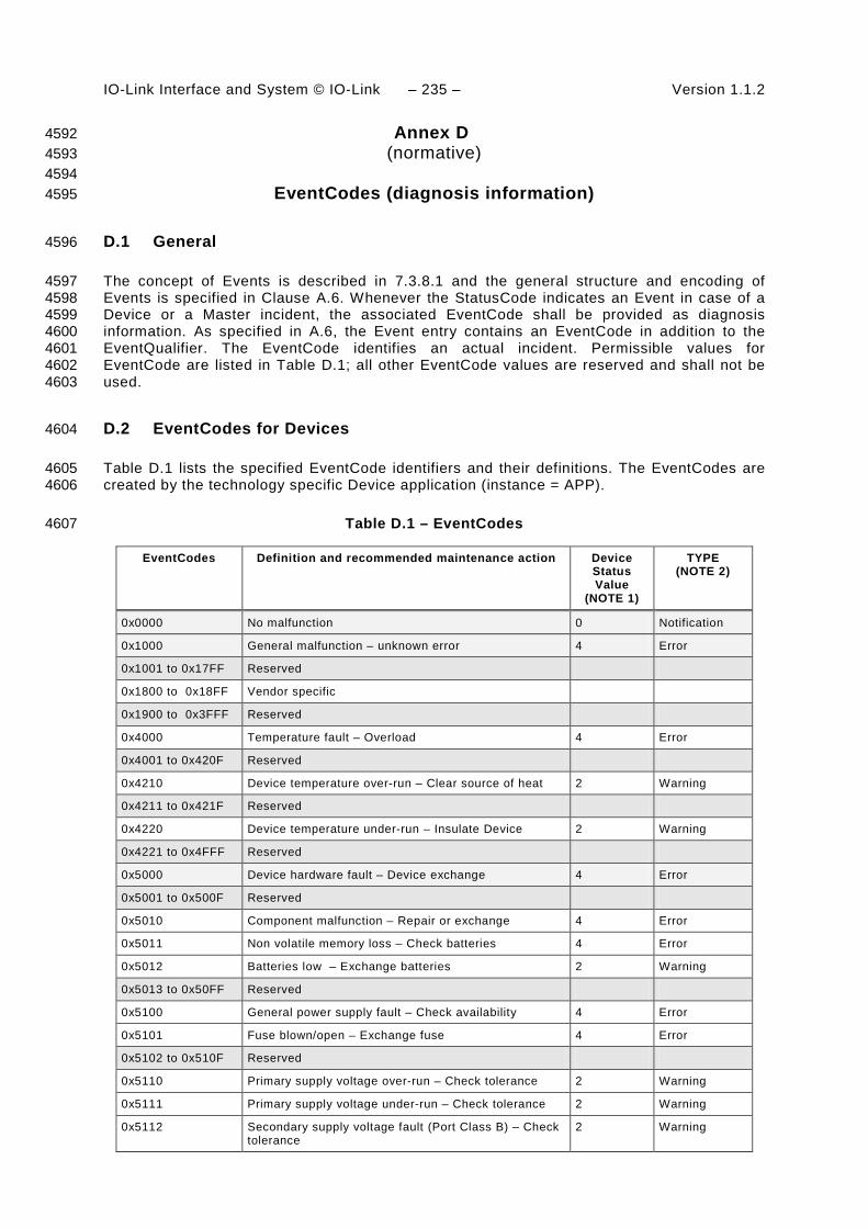
IO-Link Interface and System © IO-Link – 235 – Version 1.1.2
Annex D 4592 (normative) 4593
4594 EventCodes (diagnosis information) 4595
D.1 General 4596
The concept of Events is described in 7.3.8.1 and the general structure and encoding of 4597 Events is specified in Clause A.6. Whenever the StatusCode indicates an Event in case of a 4598 Device or a Master incident, the associated EventCode shall be provided as diagnosis 4599 information. As specified in A.6, the Event entry contains an EventCode in addition to the 4600 EventQualifier. The EventCode identifies an actual incident. Permissible values for 4601 EventCode are listed in Table D.1; all other EventCode values are reserved and shall not be 4602 used. 4603
D.2 EventCodes for Devices 4604
Table D.1 lists the specified EventCode identifiers and their definitions. The EventCodes are 4605 created by the technology specific Device application (instance = APP). 4606
Table D.1 – EventCodes 4607
EventCodes Definition and recommended maintenance action Device Status Value
(NOTE 1)
TYPE (NOTE 2)
0x0000 No malfunction 0 Notification
0x1000 General malfunction – unknown error 4 Error
0x1001 to 0x17FF Reserved
0x1800 to 0x18FF Vendor specific
0x1900 to 0x3FFF Reserved
0x4000 Temperature fault – Overload 4 Error
0x4001 to 0x420F Reserved
0x4210 Device temperature over-run – Clear source of heat 2 Warning
0x4211 to 0x421F Reserved
0x4220 Device temperature under-run – Insulate Device 2 Warning
0x4221 to 0x4FFF Reserved
0x5000 Device hardware fault – Device exchange 4 Error
0x5001 to 0x500F Reserved
0x5010 Component malfunction – Repair or exchange 4 Error
0x5011 Non volatile memory loss – Check batteries 4 Error
0x5012 Batteries low – Exchange batteries 2 Warning
0x5013 to 0x50FF Reserved
0x5100 General power supply fault – Check availability 4 Error
0x5101 Fuse blown/open – Exchange fuse 4 Error
0x5102 to 0x510F Reserved
0x5110 Primary supply voltage over-run – Check tolerance 2 Warning
0x5111 Primary supply voltage under-run – Check tolerance 2 Warning
0x5112 Secondary supply voltage fault (Port Class B) – Check tolerance
2 Warning

Version 1.1.2 – 236 – IO-Link Interface and System © IO-Link
0x5113 to 0x5FFF Reserved
0x6000 Device software fault – Check firmware revision 4 Error
0x6001 to 0x631F Reserved
0x6320 Parameter error – Check data sheet and values 4 Error
0x6321 Parameter missing – Check data sheet 4 Error
0x6322 to 0x634F Reserved
0x6350 Parameter changed – Check configuration 4 Error
0x6351 to 0x76FF Reserved
0x7700 Wire break of a subordinate device – Check installation 4 Error
0x7701 to 0x770F Wire break of subordinate device 1 …device 15 – Check installation
4 Error
0x7710 Short circuit – Check installation 4 Error
0x7711 Ground fault – Check installation 4 Error
0x7712 to 0x8BFF Reserved
0x8C00 Technology specific application fault – Reset Device 4 Error
0x8C01 Simulation active – Check operational mode 3 Warning
0x8C02 to 0x8C0F Reserved
0x8C10 Process variable range over-run – Process Data uncertain
2 Warning
0x8C11 to 0x8C1F Reserved
0x8C20 Measurement range over-run – Check application 4 Error
0x8C21 to 0x8C2F Reserved
0x8C30 Process variable range under-run – Process Data uncertain
2 Warning
0x8C31 to 0x8C3F Reserved
0x8C40 Maintenance required – Cleaning 1 Notification
0x8C41 Maintenance required – Refill 1 Notification
0x8C42 Maintenance required – Exchange wear and tear parts 1 Notification
0x8C43 to 0x8C9F Reserved
0x8CA0 to 0x8DFF Vendor specific
0x8E00 to 0xAFFF Reserved
0xB000 to 0xBFFF Reserved for profiles
0xC000 to 0xFEFF Reserved
0xFF00 to 0xFFFF SDCI specific EventCodes (see Table D.2)
NOTE 1 See B.2.18 NOTE 2 See Table A.19
4608 Table D.2 lists basic SDCI Events related to system management, Device or Master appli-4609 cation, and specifies how they are encoded. Other types of Events may be reported but are 4610 not specified in this standard. Processing of these Events by the Master is vendor specific. 4611
Table D.2 – Basic SDCI EventCodes 4612
Incident a Origin Instance Name EventCode Action Remark
System management
Mode indication
LOCAL DL NEW_SLAVE 0xFF21 PD stop See Clause 11

IO-Link Interface and System © IO-Link – 237 – Version 1.1.2
Incident a Origin Instance Name EventCode Action Remark
System management
Device communi-cation lost
LOCAL APP DEV_COM_ LOST
0xFF22 - See Clause 11
Data Storage identification mismatch
LOCAL APP DS_IDENT_ MISMATCH
0xFF23 - See Clause 11
Data Storage buffer overflow
LOCAL APP DS_BUFFER_OVERFLOW
0xFF24 - See Clause 11
Data Storage parameter access denied
LOCAL APP DS_ACCESS_DENIED
0xFF25 - See Clause 11
Unspecified
Incorrect Event signalling
LOCAL DL EVENT 0xFF31 Event.ind See Clause 11
Device specific application
Data Storage upload request
REMOTE APP DS_UPLOAD_REQ
0xFF91 Event.ind
Reserved REMOTE APP 0xFF98 Event.ind Shall not be used
a All Events are of StatusCode type 2 (with details), EventQualifier type "Notification", EventQualifier Mode "Single-shot"
4613

Version 1.1.2 – 238 – IO-Link Interface and System © IO-Link
Annex E 4614 (normative) 4615
4616 Data types 4617
E.1 General 4618
This annex specifies basic and composite data types. Examples demonstrate the structures 4619 and the transmission aspects of data types for singular use or in a packed manner. 4620
NOTE More examples are available in [6]. 4621
E.2 Basic data types 4622
E.2.1 General 4623
The coding of basic data types is shown only for singular use, which is characterized by 4624
• Process Data consisting of one basic data type 4625
• Parameter consisting of one basic data type 4626
• Subindex (>0) access on individual data items of parameters of composite data types 4627 (arrays, records) 4628
E.2.2 BooleanT 4629
A BooleanT is representing a data type that can have only two different values i.e. TRUE and 4630 FALSE. The data type is specified in Table E.1. For singular use the coding is shown in Table 4631 E.2. A sender shall always use 0xFF for 'TRUE' or 0x00 for 'FALSE'. A receiver can interpret 4632 the range from 0x01 through 0xFF for 'TRUE' and shall interpret 0x00 for 'FALSE' to simplify 4633 implementations. The packed form is demonstrated in Table E.22 and Figure E.8. 4634
Table E.1 – BooleanT 4635
Data type name Value range Resolution Length
BooleanT TRUE / FALSE - 1 bit or 1 octet
4636 Table E.2 – BooleanT coding 4637
Bit 7 6 5 4 3 2 1 0 Values
TRUE 1 1 1 1 1 1 1 1 0xFF
FALSE 0 0 0 0 0 0 0 0 0x00
4638
E.2.3 UIntegerT 4639
A UIntegerT is representing an unsigned number depicted by 2 up to 64 bits ("enumerated"). 4640 The number is accommodated and right-aligned within the following permitted octet con-4641 tainers: 1, 2, 4, or 8. High order padding bits are filled with "0". Coding examples are shown in 4642 Figure E.1. 4643

IO-Link Interface and System © IO-Link – 239 – Version 1.1.2
00 00 00 00 11 11 00 11
11 11 00 11
Padding bits = 0
Value = 13
4 bit 1 octet
00 00 00 00 00 00 00 00
11
Padding bits = 0
Value = 93786
17 bit 4 octets
00 11 11 00 11 11 11 00 00 11 00 11 11 00 11 00
00 00 00 00 00 00 00 11 00 11 11 00 11 11 11 00 00 11 00 11 11 00 11 00
4644
Figure E.1 – Coding examples of UIntegerT 4645
The data type UIntegerT is specified in Table E.3 for singular use. 4646
Table E.3 – UIntegerT 4647
Data type name Value range Resolution Length
UIntegerT 0 … 2bitlength - 1 1 1 octet, or 2 octets, or 4 octets, or 8 octets
NOTE 1 High order padding bits are filled with "0".
NOTE 2 Most significant octet (MSO) sent first.
4648 E.2.4 IntegerT 4649
An IntegerT is representing a signed number depicted by 2 up to 64 bits. The number is 4650 accommodated within the following permitted octet containers: 1, 2, 4, or 8 and right-aligned 4651 and extended correctly signed to the chosen number of bits. The data type is specified in 4652 Table E.4 for singular use. SN represents the sign with "0" for all positive numbers and zero, 4653 and "1" for all negative numbers. Padding bits are filled with the content of the sign bit (SN). 4654
Table E.4 – IntegerT 4655
Data type name Value range Resolution Length
IntegerT -2bitlength -1 … 2bitlength -1 - 1 1 1 octet, or 2 octets, or 4 octets, or 8 octets
NOTE 1 High order padding bits are filled with the value of the sign bit (SN).
NOTE 2 Most significant octet (MSO) sent first (lowest respective octet number in Table E.5).
4656
The 4 coding possibilities in containers are listed in Table E.5 through Table E.8. 4657
4658
4659

Version 1.1.2 – 240 – IO-Link Interface and System © IO-Link
Table E.5 – IntegerT coding (8 octets) 4660
Bit 7 6 5 4 3 2 1 0 Container
Octet 1 SN 262 261 260 259 258 257 256 8 octets
Octet 2 255 254 253 252 251 250 249 248
Octet 3 247 246 245 244 243 242 241 240
Octet 4 239 238 237 236 235 234 233 232
Octet 5 231 230 229 228 227 226 225 224
Octet 6 223 222 221 220 219 218 217 216
Octet 7 215 214 213 212 211 210 29 28
Octet 8 27 26 25 24 23 22 21 20
4661
Table E.6 – IntegerT coding (4 octets) 4662
Bit 7 6 5 4 3 2 1 0 Container
Octet 1 SN 230 229 228 227 226 225 224 4 octets
Octet 2 223 222 221 220 219 218 217 216
Octet 3 215 214 213 212 211 210 29 28
Octet 4 27 26 25 24 23 22 21 20
4663
Table E.7 – IntegerT coding (2 octets) 4664
Bit 7 6 5 4 3 2 1 0 Container
Octet 1 SN 214 213 212 211 210 29 28 2 octets
Octet 2 27 26 25 24 23 22 21 20
4665
Table E.8 – IntegerT coding (1 octet) 4666
Bit 7 6 5 4 3 2 1 0 Container
Octet 1 SN 26 25 24 23 22 21 20 1 octet
4667
Coding examples within containers are shown in Figure E.2 4668

IO-Link Interface and System © IO-Link – 241 – Version 1.1.2
11 11 11 11 11 11 00 00
11 11 00 00
Padding bits = 1 (SN)
Value = -4
11 11 11 11 11 11 11 11
11
Padding bits = 1 (SN)
Value = -28250 17 bit 4 octets 11 00 00 11 00 00 00 11 11 00 11 00 00 11 11 00
11 11 11 11 11 11 11 11 11 00 00 11 00 00 00 11 11 00 11 00 00 11 11 00
SNSN = 0: positive numbers and zero SN = 1: negative numbers(Two's complement)
SN
SN
00 00 00 00 00 11 00 00
00 11 00 00
Padding bits = 0 (SN)
Value = +4
SN
4669
Figure E.2 – Coding examples of IntegerT 4670
E.2.5 Float32T 4671
A Float32T is representing a number specified by IEEE Std 754-1985 as single precision (32 4672 bit). Table E.9 gives the definition and Table E.10 the coding. SN represents the sign with "0" 4673 for all positive numbers and zero, and "1" for all negative numbers. 4674
Table E.9 – Float32T 4675
Data type name Value range Resolution Length
Float32T See IEEE Std 754-1985 See IEEE Std 754-1985 4 octets
4676 Table E.10 – Coding of Float32T 4677
Bits 7 6 5 4 3 2 1 0
Octet 1 SN Exponent (E)
20 27 26 25 24 23 22 21
Octet 2 (E) Fraction (F)
20 2-1 2-2 2-3 2-4 2-5 2-6 2-7
Octet 3 Fraction (F)
2-8 2-9 2-10 2-11 2-12 2-13 2-14 2-15
Octet 4 Fraction (F)
2-16 2-17 2-18 2-19 2-20 2-21 2-22 2-23
4678 In order to realize negative exponent values a special exponent encoding mechanism is set in 4679 place as follows: 4680
The Float32T exponent (E) is encoded using an offset binary representation, with the zero 4681 offset being 127; also known as exponent bias in IEEE Std 754-1985. 4682
Emin = 0x01 - 0x7F = -126 4683
Emax = 0xFE - 0x7F = 127 4684
Exponent bias = 0x7F = 127 4685

Version 1.1.2 – 242 – IO-Link Interface and System © IO-Link
Thus, as defined by the offset binary representation, in order to get the true exponent the 4686 offset of 127 shall be subtracted from the stored exponent. 4687
E.2.6 StringT 4688
A StringT is representing an ordered sequence of symbols (characters) with a variable or 4689 fixed length of octets (maximum of 232 octets) coded in US-ASCII (7 bit) or UTF-8. UTF-8 4690 uses one octet for all ASCII characters and up to 4 octets for other characters. 0x00 is not 4691 permitted as a character. Table E.11 gives the definition. 4692
Table E.11 – StringT 4693
Data type name Encoding Standards Length
StringT US-ASCII see ISO/IEC 646 Any length of character string with a maximum of 232 octets
UTF-8 see ISO/IEC 10646
NOTE The length may be obtained from a Device's IODD via the attribute 'fixedLength'.
4694 An instance of StringT can be shorter than defined by the IODD attribute 'fixedLength'. 0x00 4695 shall be used for the padding of unused octets. Character strings can be transmitted in their 4696 actual length in case of singular access (see Figure E.3). Optimization for transmission is 4697 possible by omitting the padding octets if the IODD attribute 'fixedLengthRestriction' is not 4698 set. The receiver can deduce the original length from the length of the ISDU or by searching 4699 the first NULL (0x00) character (See A.5.2 and A.5.3). 4700
0x480x48 0x450x45 0x4C0x4C 0x4C0x4C 0x4F0x4F 0x000x00 0x000x000x480x48 0x450x45 0x4C0x4C 0x4C0x4C 0x4F0x4F 0x000x00 0x000x00
H E L L O
Transmission
Sender: 'fixedLength' =7Padding of unused octets = 0x00
0x480x48 0x450x45 0x4C0x4C 0x4C0x4C 0x4F0x4F0x480x48 0x450x45 0x4C0x4C 0x4C0x4C 0x4F0x4FTransmission options:StringT can be transmitted in condensed form orunmodified.
0x480x48 0x450x45 0x4C0x4C 0x4C0x4C 0x4F0x4F 0x000x00 0x000x000x480x48 0x450x45 0x4C0x4C 0x4C0x4C 0x4F0x4F 0x000x00 0x000x00Receiver: 'fixedLength' =7Padding of unused octets = 0x00
Octet number0 1 2 3 4 5 6
4701
Figure E.3 – Singular access of StringT 4702
E.2.7 OctetStringT 4703
An OctetStringT is representing an ordered sequence of octets with a fixed length (maximum 4704 of 232 octets). Table E.12 gives the definition and Figure E.4 a coding example for a fixed 4705 length of 7. 4706
Table E.12 – OctetStringT 4707
Data type name Value range Standards Length
OctetStringT 0x00 … 0xFF per octet - Fixed length with a maximum of 232 octets
NOTE The length may be obtained from a Device's IODD via the attribute 'fixedLength'.
4708

IO-Link Interface and System © IO-Link – 243 – Version 1.1.2
0x1F0x1F 0x0A0x0A 0x230x23 0xAA0xAA 0xBB0xBB 0xA10xA1 0xD00xD0
Octet number0 1 2 3 4 5 6
4709
Figure E.4 – Coding example of OctetStringT 4710
E.2.8 TimeT 4711
A TimeT is based on the RFC 1305 standard and composed of two unsigned values that 4712 express the network time related to a particular date. Its semantic has changed from 4713 RFC 1305 according to Figure E.5. Table E.13 gives the definition and Table E.14 the coding 4714 of TimeT. 4715
The first element is a 32-bit unsigned integer data type that provides the network time in 4716 seconds since 1900-01-01 0.00,00(UTC) or since 2036-02-07 6.28,16(UTC) for time values 4717 less than 0x9DFF4400, which represents the 1984-01-01 0:00,00(UTC). The second element 4718 is a 32-bit unsigned integer data type that provides the fractional portion of seconds in 4719 1/232 s. Rollovers after 136 years are not automatically detectable and shall be maintained by 4720 the application. 4721
Time1900-01-01 1984-01-01 2036-02-07
RFC 1305 Standard
TimeT
0x00000000 s 0x9DFF4400 s 0xFFFFFFFF s
Time1900-01-01 1984-01-01 2036-02-07
RFC 1305 Standard
TimeT
0x00000000 s 0x9DFF4400 s 0xFFFFFFFF s 4722
Figure E.5 – Definition of TimeT 4723
Table E.13 – TimeT 4724
Data type name Value range Resolution Length
TimeT Octet 1 to 4 (see Table E.14): 0 ≤ i ≤ (232-1)
s (Seconds) 8 Octets (32 bit unsigned integer + 32 bit unsigned integer)
Octet 5 to 8 (see Table E.14): 0 ≤ i ≤ (232-1)
(1/232) s
NOTE 32 bit unsigned integer are normal computer science data types
4725
4726
4727
4728
4729

Version 1.1.2 – 244 – IO-Link Interface and System © IO-Link
Table E.14 – Coding of TimeT 4730
Bit 7 6 5 4 3 2 1 0 Definitions
Octet 1 231 230 229 228 227 226 225 224 Seconds since 1900-01-01 0.00,00 or since 2036-02-07 6.28,16 when time value less than 0x9DFF4400.00000000
Octet 2 223 222 221 220 219 218 217 216
Octet 3 215 214 213 212 211 210 29 28
Octet 4 27 26 25 24 23 22 21 20
Octet 5 231 230 229 228 227 226 225 224 Fractional part of seconds. One unit is 1/(232) s
Octet 6 223 222 221 220 219 218 217 216
Octet 7 215 214 213 212 211 210 29 28
Octet 8 27 26 25 24 23 22 21 20
MSB LSB MSB = Most significant bit LSB = Least significant bit
4731 E.2.9 TimeSpanT 4732
A TimeSpanT is a 64-bit integer value i.e. a two’s complement binary number with a length of 4733 eight octets, providing the network time difference in fractional portion of seconds in 1/232 4734 seconds. Table E.15 gives the definition and Table E.16 the coding of TimeSpanT. 4735
Table E.15 – TimeSpanT 4736
Data type name Value range Resolution Length
TimeSpanT Octet 1 to 8 (see Table E.16): - 263 ≤ i ≤ (263-1)
(1/232) s 8 octets (64 bit integer)
NOTE 64 bit integer is a normal computer science data type
4737 Table E.16 – Coding of TimeSpanT 4738
Bit 7 6 5 4 3 2 1 0 Definitions
Octet 1 263 262 261 260 259 258 257 256 Fractional part of seconds as 64 bit integer. One unit is 1/(232) s. Octet 2 255 254 253 252 251 250 249 248
Octet 3 247 246 245 244 243 242 241 240
Octet 4 239 238 237 236 235 234 233 232
Octet 5 231 230 229 228 227 226 225 224
Octet 6 223 222 221 220 219 218 217 216
Octet 7 215 214 213 212 211 210 29 28
Octet 8 27 26 25 24 23 22 21 20
MSB LSB MSB = Most significant bit LSB = Least significant bit
4739

IO-Link Interface and System © IO-Link – 245 – Version 1.1.2
E.3 Composite data types 4740
E.3.1 General 4741
Composite data types are combinations of basic data types only. A composite data type 4742 consists of several basic data types packed within a sequence of octets. Unused bit space 4743 shall be padded with "0". 4744
E.3.2 ArrayT 4745
An ArrayT addressed by an Index is a data structure with data items of the same data type. 4746 The individual data items are addressable by the Subindex. Subindex 0 addresses the whole 4747 array within the Index space. The structuring rules for arrays are given in Table E.17. 4748
Table E.17 – Structuring rules for ArrayT 4749
Rule number Rule specification
1 The Subindex data items are packed in a row without gaps describing an octet sequence
2 The highest Subindex data item n starts right-aligned within the octet sequence
3 UIntegerT and IntegerT with a length of ≥ 58 bit and < 64 bit are not permitted
4750 Table E.18 and Figure E.6 give an example for the access of an array. Its content is a set of 4751 parameters of the same basic data type. 4752
Table E.18 – Example for the access of an ArrayT 4753
Index Subindex Offset Data items Data Type
66 1 12 0x2 IntegerT, 'bitLength' = 3
2 9 0x6
3 6 0x4
4 3 0x7
5 0 0x5
4754
00 11 00 11 11 00 11
Bit 0
Bit offset: 3
"Subindex5"
Transmissiondirection
00 00 11 11 11 11 00 11
"Subindex4"
"Subindex3"
"Subindex2"
"Subindex1"
Bit 15
06912
4755
Figure E.6 – Example of an ArrayT data structure 4756
E.3.3 RecordT 4757
A record addressed by an Index is a data structure with data items of different data types. The 4758 Subindex allows addressing individual data items within the record on certain bit positions. 4759
NOTE Bit positions within a RecordT may be obtained from the IODD of the particular Device. 4760
The structuring rules for records are given in Table E.19. 4761

Version 1.1.2 – 246 – IO-Link Interface and System © IO-Link
Table E.19 – Structuring rules for RecordT 4762
Rule number Rule specification
1 The Subindices within the IODD shall be listed in ascending order from 1 to n describing an octet sequence. Gaps within the list of Subindices are allowed
2 Bit offsets shall always be indicated within this octet sequence (may show no strict order in the IODD)
3 The bit offset starts with the last octet within the sequence; this octet starts with offset 0 for the least significant bit and offset 7 for the most significant bit
4 The following data types shall always be aligned on octet boundaries: Float32T, StringT, OctetStringT, TimeT, and TimeSpanT
5 UIntegerT and IntegerT with a length of ≥ 58 bit shall always be aligned on one side of an octet boundary
6 It is highly recommended for UIntegerT and IntegerT with a length of ≥ 8 bit to align always on one side of an octet boundary
7 It is highly recommended for UIntegerT and IntegerT with a length of < 8 bit not to cross octet boundaries
8 A bit position shall not be used by more than one record item
4763 Table E.20 gives an example 1 for the access of a RecordT. It consists of varied parameters 4764 named "Status", "Text", and "Value". 4765
Table E.20 – Example 1 for the access of a RecordT 4766
Index Subindex Offset Data items Data Type Name
47
1 88 0x23 0x45 UIntegerT, 'bitLength' = 16
Status
2 32 H E L L O 0x00 0x00 StringT, 'fixedLength' = 7
Text
3 0 0x56 0x12 0x22 0x34 UIntegerT, 'bitLength' = 32
Value
NOTE 'bitLength' and 'fixedLength' are defined in the IODD of the particular Device.
4767 Table E.21 gives an example 2 for the access of a RecordT. It consists of varied parameters 4768 named "Level", "Min", and "Max". Figure E.7 shows the corresponding data structure. 4769
Table E.21 – Example 2 for the access of a RecordT 4770
Index Subindex Offset Data items Data Type Name
46
1 2 0x32 0xF1 UIntegerT, 'bitLength' = 14
Level
2 1 FALSE BooleanT Min
3 0 TRUE BooleanT Max
NOTE 'bitLength' is defined in the IODD of the particular Device.

IO-Link Interface and System © IO-Link – 247 – Version 1.1.2
11 11 00 00 11 00 11 11
Bit 0
Bit offset:
Transmissiondirection
11 11 00 00 00 11 00 11
"Level"
Bit 15
012
"Min""Max" 4771
Figure E.7 – Example 2 of a RecordT structure 4772
Table E.22 gives an example 3 for the access of a RecordT. It consists of varied parameters 4773 named "Control" through "Enable". Figure E.8 demonstrates the corresponding RecordT 4774 structure of example 3 with the bit offsets. 4775
Table E.22 – Example 3 for the access of a RecordT 4776
Index Subindex Offset Data items Data Type Name
45
1 32 TRUE BooleanT NewBit
2 33 FALSE BooleanT DR4
3 34 FALSE BooleanT CR3
4 35 TRUE BooleanT CR2
5 38 TRUE BooleanT Control
6 16 0xF8 0x23 OctetStringT, 'fixedLength' = 2
Setpoint
7 8 0x41 StringT, 'fixedLength' = 1
Unit
8 0 0xC3 OctetStringT, 'fixedLength' = 1
Enable
NOTE 'fixedLength' is defined in the IODD of the particular Device
4777
Bit 39
0xF8 0x230xF8 0x23 0x410x41 0xC30xC3
Bit 0
Bit offset: 38 35 32 16 8
"Setpoint""Setpoint" "Unit""Unit" "Enable""Enable"
Transmissiondirection
4778
Figure E.8 – Example 3 of a RecordT structure 4779
Figure E.9 shows a selective write request of a variable within the RecordT of example 3 and 4780 a write request of the complete RecordT (see A.5.7). 4781

Version 1.1.2 – 248 – IO-Link Interface and System © IO-Link
0010
Index = 45
Subindex = 4
CHKPDU
0101
0x01
Write request
0010
Index = 45
Subindex = 4
CHKPDU
0101
0x01
Write request
Selective writeof a variable withinthe record
0001
Index = 45
CHKPDU
1000
Write request
0x49
0xF8
0x41
0xC3
0x23
Write of a record
4782
Figure E.9 – Write requests for example 3 4783
4784

IO-Link Interface and System © IO-Link – 249 – Version 1.1.2
Annex F 4785 (normative) 4786
4787 Structure of the Data Storage data object 4788
Table F.1 gives the structure of a Data Storage (DS) data object within the Master (see 4789 11.3.2). 4790
Table F.1 – Structure of the stored DS data object 4791
Part Parameter name Definition Data type
Object 1
ISDU_Index ISDU Index (0 to 65535) Unsigned16
ISDU_Subindex ISDU Index (0 to 255) Unsigned8
ISDU_Length Length of the subsequent record Unsigned8
ISDU_Data Record of length ISDU_Length Record
Object 2
ISDU_Index ISDU Index (0 to 65535) Unsigned16
ISDU_Subindex ISDU Index (0 to 255) Unsigned8
ISDU_Length Length of the subsequent record Unsigned8
ISDU_Data Record of length ISDU_Length Record
----------
Object n
ISDU_Index ISDU Index (0 to 65535) Unsigned16
ISDU_Subindex ISDU Index (0 to 255) Unsigned8
ISDU_Length Length of the subsequent record Unsigned8
ISDU _Data Record of length ISDU_Length Record
4792
The Device shall calculate the required memory size by summarizing the objects 1 to n (see 4793 Table B.10, Subindex 3). 4794
The Master shall store locally in non-volatile memory the header information specified in 4795 Table F.2. See Table B.10. 4796
Table F.2 – Associated header information for stored DS data objects 4797
Part Parameter name Definition Data type
Header Parameter Checksum 32 bit CRC signature or revision counter (see 10.4.8)
Unsigned32
VendorID See B.1.8 Unsigned16
DeviceID See B.1.9 Unsigned32
FunctionID See B.1.10 Unsigned16
4798

Version 1.1.2 – 250 – IO-Link Interface and System © IO-Link
Annex G 4799 (normative) 4800
4801 Master and Device conformity 4802
G.1 Electromagnetic compatibility requirements (EMC) 4803
G.1.1 General 4804
The EMC requirements of this specification are only relevant for the SDCI interface part of a 4805 particular Master or Device. The technology functions of a Device and its relevant EMC 4806 requirements are not in the scope of this specification. For this purpose the Device specific 4807 product standards shall apply. For Master usually the EMC requirements for peripherals are 4808 specified in IEC 61131-2 or IEC 61000-6-2. 4809
To ensure proper operating conditions of the SDCI interface, the test configurations specified 4810 in section G.1.6 (Master) or G.1.7 (Device) shall be maintained during all the EMC tests. The 4811 tests required in the product standard of equipment under test (EUT) can alternatively be 4812 performed in SIO mode. 4813
G.1.2 Operating conditions 4814
It is highly recommended to evaluate the SDCI during the startup phase with the cycle times 4815 given in Table G.1. In most cases, this leads to the minimal time requirements for the 4816 performance of these tests. Alternatively, the SDCI may be evaluated during normal operation 4817 of the Device, provided that the required number of M-sequences specified in Table G.1 took 4818 place during each test. 4819
G.1.3 Performance criteria 4820
a) Performance criterion A 4821
The SDCI operating at an average cycle time as specified in Table G.1 shall not show more 4822 than six detected M-sequence errors within the number of M-sequences given in Table G.1. 4823 No interruption of communication is permitted. 4824
Table G.1 – EMC test conditions for SDCI 4825
Transmission rate
Master Device Maximum of M-sequence
errors tCYC Number of M-sequences of
TYPE_2_5 (read) (6 octets)
tCYC Number of M-sequences of TYPE_0 (read)
(4 octets)
4,8 kbit/s 18,0 ms 300 (6 000) 100 TBIT (20,84 ms)
350 (7 000) 6
38,4 kbit/s 2,3 ms 450 (9 000) 100 TBIT (2,61 ms)
500 (10 000) 6
230,4 kbit/s 0,4 ms 700 (14 000) 100 TBIT (0,44 ms)
800 (16 000) 6
NOTE The numbers of M-sequences are calculated according to the algorithm in H.2 and rounded up. The larger number of M-sequences (in brackets) are required if a certain test (for example fast transients/burst) applies interferences only with a burst/cycle ratio (see Table G.2)
4826
b) Performance Criterion B 4827

IO-Link Interface and System © IO-Link – 251 – Version 1.1.2
The error rate of criterion A shall also be satisfied after but not during the test. No change of 4828 actual operating state (e.g. permanent loss of communication) or stored data is allowed. 4829
G.1.4 Required immunity tests 4830
Table G.2 specifies the EMC tests to be performed. 4831
Table G.2 – EMC test levels 4832
Phenomena Test Level Performance Criterion
Constraints
Electrostatic discharges (ESD)
IEC 61000-4-2
Air discharge: ± 8 kV
Contact discharge: ± 4 kV
B See G.1.4, a)
Radio-frequency electromagnetic field. Amplitude modulated
IEC 61000-4-3
80 MHz – 1 000 MHz 10 V/m
1 400 MHz – 2 000 MHz 3 V/m
2 000 MHz – 2 700 MHz 1 V/m
A See G.1.4, a) and G.1.4, b)
Fast transients (Burst)
IEC 61000-4-4
± 1 kV A 5 kHz only. The number of M-sequences in Table G.1 shall be increased by a factor of 20 due to the burst/cycle ratio 15 ms/300 ms. See G.1.4, c)
± 2 kV B
Surge
IEC 61000-4-5
Not required for an SDCI link (SDCI link is limited to 20 m)
-
Radio-frequency common mode
IEC 61000-4-6
0,15 MHz – 80 MHz 10 VEMF
A See G.1.4, b) and G.1.4, d)
Voltage dips and interruptions
IEC 61000-4-11
Not required for an SDCI link
4833 The following requirements also apply as specified in Table G.2. 4834
a) As this phenomenon influences the entire device under test, an existing device specific product standard 4835 shall take precedence over the test levels specified here. 4836
b) The test shall be performed with a step size of 1 % and a dwell of 1 s. If a single M-sequence error occurs at 4837 a certain frequency, that frequency shall be tested until the number of M-sequences according to Table G.1 4838 has been transmitted or until 6 M-sequence errors have occurred. 4839
c) Depending on the transmission rate the test time varies. The test time shall be at least one minute (with the 4840 transmitted M-sequences and the permitted errors increased accordingly). 4841
d) This phenomenon is expected to influence most probably the EUTs internal analog signal processing and 4842 only with a very small probability the functionality of the SDCI communication. Therefore an existing device 4843 specific product standard shall take precedence over the test levels specified here. 4844
G.1.5 Required emission tests 4845
The definition of emission limits is not in the scope of this specification. The requirements of 4846 the Device specific product family or generic standards apply, usually for general industrial 4847 environments the IEC 61000-6-4. 4848
All emission tests shall be performed at the fastest possible communication rate with the 4849 fastest cycle time. 4850

Version 1.1.2 – 252 – IO-Link Interface and System © IO-Link
G.1.6 Test configurations for Master 4851
G.1.6.1 General rules 4852
The following rules apply for the test of Masters: 4853
• In the following test setup diagrams only the SDCI and the power supply cables are 4854 shown. All other cables shall be treated as required by the relevant product standard. 4855
• Grounding of the Master and the Devices shall be according to the relevant product 4856 standard or manual. 4857
• Where not otherwise stated, the SDCI cable shall have an overall length of 20 m. Excess 4858 length laid as an inductive coil with a diameter of 0,3 m, where applicable mounted 0,1 m 4859 above reference ground. 4860
• Where applicable, the auxiliary Devices shall be placed 10 cm above RefGND. 4861
• A typical test configuration consists of the Master and two Devices, except for the RF 4862 common mode test, where only one Device shall be used. 4863
• Each port shall fulfill the EMC requirements. 4864
G.1.6.2 Electrostatic discharges 4865
Figure G.1 shows the test setup for electrostatic discharge according to IEC 61000-4-2. 4866
D =0,3 m
d ≥ 1,0 m
EUT(Master)
AUX 1(Device)
AUX 2(Device)
Power Supply
d ≥ 1,0 m 4867
Figure G.1 – Test setup for electrostatic discharge (Master) 4868
G.1.6.3 Radio-frequency electromagnetic field 4869
Figure G.2 shows the test setup for radio-frequency electromagnetic field according to 4870 IEC 61000-4-3. 4871
D = 0,3 m
EUT(Master)
AUX 1(Device)Power
Supply
l = 1,0 m l = 1,0 m
AUX 2(Device)
Ferrite clamp or other decoupling
Uniform area
4872
Figure G.2 – Test setup for RF electromagnetic field (Master) 4873
G.1.6.4 Fast transients (burst) 4874
Figure G.3 shows the test setup for fast transients according to IEC 61000-4-4. No coupling 4875 into SDCI line to AUX 2 is required. 4876
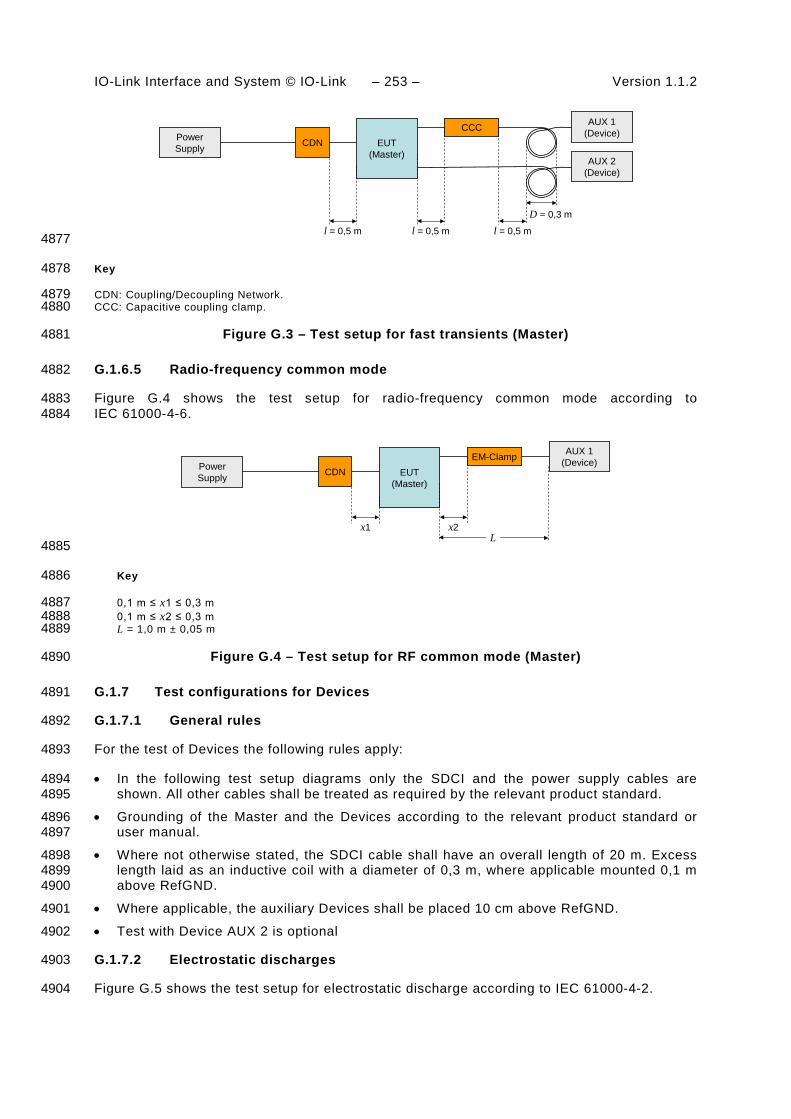
IO-Link Interface and System © IO-Link – 253 – Version 1.1.2
D = 0,3 m
EUT(Master)
AUX 1(Device)Power
Supply
l = 0,5 m
AUX 2(Device)
CDNCCC
l = 0,5 m l = 0,5 m 4877
Key 4878
CDN: Coupling/Decoupling Network. 4879 CCC: Capacitive coupling clamp. 4880
Figure G.3 – Test setup for fast transients (Master) 4881
G.1.6.5 Radio-frequency common mode 4882
Figure G.4 shows the test setup for radio-frequency common mode according to 4883 IEC 61000-4-6. 4884
EUT(Master)
AUX 1(Device)Power
Supply CDNEM-Clamp
x1 x2L
4885
Key 4886
0,1 m ≤ x1 ≤ 0,3 m 4887 0,1 m ≤ x2 ≤ 0,3 m 4888 L = 1,0 m ± 0,05 m 4889
Figure G.4 – Test setup for RF common mode (Master) 4890
G.1.7 Test configurations for Devices 4891
G.1.7.1 General rules 4892
For the test of Devices the following rules apply: 4893
• In the following test setup diagrams only the SDCI and the power supply cables are 4894 shown. All other cables shall be treated as required by the relevant product standard. 4895
• Grounding of the Master and the Devices according to the relevant product standard or 4896 user manual. 4897
• Where not otherwise stated, the SDCI cable shall have an overall length of 20 m. Excess 4898 length laid as an inductive coil with a diameter of 0,3 m, where applicable mounted 0,1 m 4899 above RefGND. 4900
• Where applicable, the auxiliary Devices shall be placed 10 cm above RefGND. 4901
• Test with Device AUX 2 is optional 4902
G.1.7.2 Electrostatic discharges 4903
Figure G.5 shows the test setup for electrostatic discharge according to IEC 61000-4-2. 4904
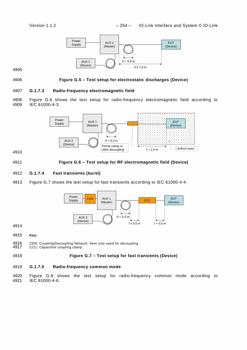
Version 1.1.2 – 254 – IO-Link Interface and System © IO-Link
D = 0,3 m
d ≥ 1,0 m
AUX 1(Master)
EUT(Device)
AUX 2(Device)
Power Supply
4905
Figure G.5 – Test setup for electrostatic discharges (Device) 4906
G.1.7.3 Radio-frequency electromagnetic field 4907
Figure G.6 shows the test setup for radio-frequency electromagnetic field according to 4908 IEC 61000-4-3. 4909
D = 0,3 m
AUX 1(Master)
EUT(Device)
AUX 2(Device)
Power Supply
l = 1,0 m Uniform areaFerrite clamp or other decoupling
4910
Figure G.6 – Test setup for RF electromagnetic field (Device) 4911
G.1.7.4 Fast transients (burst) 4912
Figure G.7 shows the test setup for fast transients according to IEC 61000-4-4. 4913
D = 0,3 m
AUX 1(Master)
EUT(Device)
AUX 2(Device)
Power Supply CCC
l = 0,5 m l = 0,5 m
CDN
4914
Key: 4915
CDN: Coupling/Decoupling Network, here only used for decoupling 4916 CCC: Capacitive coupling clamp. 4917
Figure G.7 – Test setup for fast transients (Device) 4918
G.1.7.5 Radio-frequency common mode 4919
Figure G.8 shows the test setup for radio-frequency common mode according to 4920 IEC 61000-4-6. 4921
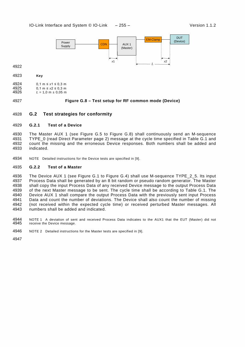
IO-Link Interface and System © IO-Link – 255 – Version 1.1.2
AUX 1(Master)
DUT(Device)Power
Supply CDNEM-Clamp
x1 x2L
4922
Key 4923
0,1 m ≤ x1 ≤ 0,3 m 4924 0,1 m ≤ x2 ≤ 0,3 m 4925 L = 1,0 m ± 0,05 m 4926
Figure G.8 – Test setup for RF common mode (Device) 4927
G.2 Test strategies for conformity 4928
G.2.1 Test of a Device 4929
The Master AUX 1 (see Figure G.5 to Figure G.8) shall continuously send an M-sequence 4930 TYPE_0 (read Direct Parameter page 2) message at the cycle time specified in Table G.1 and 4931 count the missing and the erroneous Device responses. Both numbers shall be added and 4932 indicated. 4933
NOTE Detailed instructions for the Device tests are specified in [9]. 4934
G.2.2 Test of a Master 4935
The Device AUX 1 (see Figure G.1 to Figure G.4) shall use M-sequence TYPE_2_5. Its input 4936 Process Data shall be generated by an 8 bit random or pseudo random generator. The Master 4937 shall copy the input Process Data of any received Device message to the output Process Data 4938 of the next Master message to be sent. The cycle time shall be according to Table G.1. The 4939 Device AUX 1 shall compare the output Process Data with the previously sent input Process 4940 Data and count the number of deviations. The Device shall also count the number of missing 4941 (not received within the expected cycle time) or received perturbed Master messages. All 4942 numbers shall be added and indicated. 4943
NOTE 1 A deviation of sent and received Process Data indicates to the AUX1 that the EUT (Master) did not 4944 receive the Device message. 4945
NOTE 2 Detailed instructions for the Master tests are specified in [9]. 4946
4947

Version 1.1.2 – 256 – IO-Link Interface and System © IO-Link
Annex H 4948 (informative) 4949
4950 Residual error probabilities 4951
H.1 Residual error probability of the SDCI data integrity mechanism 4952
Figure H.1 shows the residual error probability (REP) of the SDCI data integrity mechanism 4953 consisting of the checksum data integrity procedure ("XOR6") as specified in A.1.6 and the 4954 UART parity. The diagram refers to IEC 60870-5-1 with its data integrity class I2 for a 4955 minimum Hamming distance of 4 (red dotted line). 4956
Bit error probability (BEP)
Res
idua
l err
or p
roba
bilit
y (R
EP)
10,10,011* 10-31* 10-4
1
0,1
0,01
1* 10-3
1* 10-4
1* 10-5
1* 10-6
1* 10-7
1* 10-8
1* 10-9
1* 10-10
1* 10-11
1* 10-12
1* 10-13
Integrity class I2
Hamming distance 4
KeySDCI with 2 octetsSDCI with 3 octetsSDCI with 4 octets
4957
Figure H.1 – Residual error probability for the SDCI data integrity mechanism 4958
The blue line shows the residual error curve for a data length of 2 octets. The black curve 4959 shows the residual error curve for a data length of 3 octets. The purple curve shows the 4960 residual error curve for a data length of 4 octets. 4961
H.2 Derivation of EMC test conditions 4962
The performance criterion A in G.1.3 is derived from requirements specified in IEC 61158-2 in 4963 respect to interference susceptibility and error rates (citation; "frames" translates into 4964 "messages" within this standard): 4965
• Only 1 undetected erroneous frame in 20 years at 1 600 frames/s 4966
• The ratio of undetected to detected frames shall not exceed 10-6 4967
• EMC tests shall not show more than 6 erroneous frames within 100 000 frames 4968
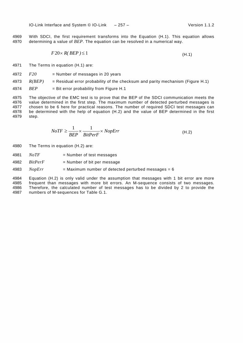
IO-Link Interface and System © IO-Link – 257 – Version 1.1.2
With SDCI, the first requirement transforms into the Equation (H.1). This equation allows 4969 determining a value of BEP. The equation can be resolved in a numerical way. 4970
120 ≤× )BEP(RF (H.1)
The Terms in equation (H.1) are: 4971
F20 = Number of messages in 20 years 4972
R(BEP) = Residual error probability of the checksum and parity mechanism (Figure H.1) 4973
BEP = Bit error probability from Figure H.1 4974
The objective of the EMC test is to prove that the BEP of the SDCI communication meets the 4975 value determined in the first step. The maximum number of detected perturbed messages is 4976 chosen to be 6 here for practical reasons. The number of required SDCI test messages can 4977 be determined with the help of equation (H.2) and the value of BEP determined in the first 4978 step. 4979
NopErrBitPerFBEP
NoTF ××≥11
(H.2)
The Terms in equation (H.2) are: 4980
NoTF = Number of test messages 4981
BitPerF = Number of bit per message 4982
NopErr = Maximum number of detected perturbed messages = 6 4983
Equation (H.2) is only valid under the assumption that messages with 1 bit error are more 4984 frequent than messages with more bit errors. An M-sequence consists of two messages. 4985 Therefore, the calculated number of test messages has to be divided by 2 to provide the 4986 numbers of M-sequences for Table G.1. 4987

Version 1.1.2 – 258 – IO-Link Interface and System © IO-Link
Annex I 4988 (informative) 4989
4990 Example sequence of an ISDU transmission 4991
Figure I.1 demonstrates an example for the transmission of ISDUs using an AL_Read service 4992 with a 16-bit Index and Subindex for 19 octets of user data with mapping to an M-sequence 4993 TYPE_2_5 for sensors and with interruption in case of an Event transmission. 4994
4995
Master DeviceFC CKT PD OD OD PD CKS
comment cycle R Com Flow Frame CHK Process OnReq Data Process CHK comment(state, action) nr W Chan. CTRL Typ Data Master Device Data E PD (state, action)
(see in Table 46) 1bit 2bit 5bit 2bit 6bit 8bit 8bit 8bit
Idle_1 0 1111 0001 10 xxxxxx xxxxxxxx 0000 0000 xxxxxxxx 0 0 xxxxxx OnReq idleISDURequest_2, transmission, 1 0111 0000 10 xxxxxx xxxxxxxx 1011 0101 xxxxxxxx 0 0 xxxxxx ISDURequest_2, receptionISDURequest_2, transmission 2 0110 0001 10 xxxxxx xxxxxxxx Index(hi) xxxxxxxx 0 0 xxxxxx ISDURequest_2, receptionISDURequest_2, transmission 3 0110 0010 10 xxxxxx xxxxxxxx Index(lo) xxxxxxxx 0 0 xxxxxx ISDURequest_2, receptionISDURequest_2, transmission 4 0110 0011 10 xxxxxx xxxxxxxx Subindex xxxxxxxx 0 0 xxxxxx ISDURequest_2, receptionISDURequest_2, transmission 5 0110 0100 10 xxxxxx xxxxxxxx CHKPDU xxxxxxxx 0 0 xxxxxx ISDURequest_2, receptionISDUWait_3, start ISDU Timer 6 1111 0000 10 xxxxxx xxxxxxxx 0000 0001 xxxxxxxx 0 0 xxxxxx ISDUWait_3, application busyISDUWait_3, inc. ISDU timer 7 1111 0000 10 xxxxxx xxxxxxxx 0000 0001 xxxxxxxx 0 0 xxxxxx ISDUWait_3, application busyISDUWait_3, inc. ISDU timer 8 1111 0000 10 xxxxxx xxxxxxxx 0000 0001 xxxxxxxx 0 0 xxxxxx ISDUWait_3, application busyISDUWait_3, inc. ISDU timer 9 1111 0000 10 xxxxxx xxxxxxxx 0000 0001 xxxxxxxx 0 0 xxxxxx ISDUWait_3, application busyISDUWait_3, inc. ISDU timer 10 1111 0000 10 xxxxxx xxxxxxxx 0000 0001 xxxxxxxx 0 0 xxxxxx ISDUWait_3, application busyISDUResponse_4, reception
Stop ISDU Timer 11 1111 0000 10 xxxxxx xxxxxxxx 1101 0001 xxxxxxxx 0 0 xxxxxx ISDUResponse_4, transmissionISDUResponse_4, reception 12 1110 0001 10 xxxxxx xxxxxxxx 0001 0011 xxxxxxxx 0 0 xxxxxx ISDUResponse_4, transmissionISDUResponse_4, reception 13 1110 0010 10 xxxxxx xxxxxxxx Data 1 xxxxxxxx 0 0 xxxxxx ISDUResponse_4, transmissionISDUResponse_4, reception 14 1110 0011 10 xxxxxx xxxxxxxx Data 2 xxxxxxxx 0 0 xxxxxx ISDUResponse_4, transmissionISDUResponse_4, reception 15 1110 0100 10 xxxxxx xxxxxxxx Data 3 xxxxxxxx 0 0 xxxxxx ISDUResponse_4, transmissionISDUResponse_4, reception 16 1110 0101 10 xxxxxx xxxxxxxx Data 4 xxxxxxxx 0 0 xxxxxx ISDUResponse_4, transmissionISDUResponse_4, reception 17 1110 0110 10 xxxxxx xxxxxxxx Data 5 xxxxxxxx 0 0 xxxxxx ISDUResponse_4, transmissionISDUResponse_4, reception 18 1110 0111 10 xxxxxx xxxxxxxx Data 6 xxxxxxxx 0 0 xxxxxx ISDUResponse_4, transmissionISDUResponse_4, reception 19 1110 1000 10 xxxxxx xxxxxxxx Data 7 xxxxxxxx 0 0 xxxxxx ISDUResponse_4, transmission
ISDUResponse_4, no response,retry in next cycle 20 1110 1001 10 Err xxxxxxxx xxxxxx
ISDUResponse_4,korrupted CHK, don' t send resp.
ISDUResponse_4, no response,retry in next cycle 21 1110 1001 10 Err xxxxxxxx xxxxxx
ISDUResponse_4,corrupted CHK, don' t send resp.
ISDUResponse_4, reception 22 1110 1001 10 xxxxxx xxxxxxxx Data 8 xxxxxxxx 0 0 xxxxxx ISDUResponse_4, transmissionISDUResponse_4, reception 34 1110 1010 10 xxxxxx xxxxxxxx Data 9 xxxxxxxx 0 0 xxxxxx ISDUResponse_4, transmissionISDUResponse_4, reception,
start eventhandler 35 1110 1011 10 xxxxxx xxxxxxxx Data 10 xxxxxxxx 1 0 xxxxxxISDUResponse_4, transmission,
freeze event
Read_Event_2, reception 36 1100 0000 10 xxxxxx xxxxxxxxDiag Statewith detail xxxxxxxx 1 0 xxxxxx Read_Event_2, transmission
Read_Event_2, reception 37 110x xxxx 10 xxxxxx xxxxxxxxEvent
qualifier xxxxxxxx 1 0 xxxxxx Read_Event_2, transmission
Command handler_2, transmissionset PDOutdata state to invalid 38 0010 0000 10 xxxxxx xxxxxxxx 1001 1001 xxxxxxxx 1 0 xxxxxx
ComandHandler_2, reception,set PDOutdata state to invalid
Read_Event_2, reception 39 110x xxxx 10 xxxxxx xxxxxxxxErrorCode
msb xxxxxxxx 1 0 xxxxxx Read_Event_2, transmission
Read_Event_2, reception 40 110x xxxx 10 xxxxxx xxxxxxxxErrorCode
lsb xxxxxxxx 1 0 xxxxxx Read_Event_2, transmissionEventConfirmation_4,
transmission,event handler idle 41 0100 0000 10 xxxxxx xxxxxxxx xxxxxxxx xxxxxxxx 0 0 xxxxxx EventConfirmation, reception
ISDUResponse_4, reception 42 1110 1100 10 xxxxxx xxxxxxxx Data 11 xxxxxxxx 0 0 xxxxxx ISDUResponse_4, transmissionISDUResponse_4, reception 43 1110 1101 10 xxxxxx xxxxxxxx Data 12 xxxxxxxx 0 0 xxxxxx ISDUResponse_4, transmissionISDUResponse_4, reception 44 1110 1110 10 xxxxxx xxxxxxxx Data 13 xxxxxxxx 0 0 xxxxxx ISDUResponse_4, transmissionISDUResponse_4, reception 45 1110 1111 10 xxxxxx xxxxxxxx Data 14 xxxxxxxx 0 0 xxxxxx ISDUResponse_4, transmissionISDUResponse_4, reception 46 1110 0000 10 xxxxxx xxxxxxxx Data 15 xxxxxxxx 0 0 xxxxxx ISDUResponse_4, transmissionISDUResponse_4, reception 47 1110 0001 10 xxxxxx xxxxxxxx Data 16 xxxxxxxx 0 0 xxxxxx ISDUResponse_4, transmissionISDUResponse_4, reception 48 1110 0010 10 xxxxxx xxxxxxxx CHKPDU xxxxxxxx 0 0 xxxxxx ISDUResponse_4, transmission
Idle_1 49 1111 0001 10 xxxxxx xxxxxxxx 0000 0000 xxxxxxxx 0 0 xxxxxx Idle_1Idle_1 50 1111 0001 10 xxxxxx xxxxxxxx 0000 0000 xxxxxxxx 0 0 xxxxxx Idle_1Idle_1 51 1111 0001 10 xxxxxx xxxxxxxx 0000 0000 xxxxxxxx 0 0 xxxxxx Idle_1Idle_1 52 1111 0001 10 xxxxxx xxxxxxxx 0000 0000 xxxxxxxx 0 0 xxxxxx Idle_1
Write Parameter, transmission 53 0011 0000 10 xxxxxx xxxxxxxx xxxxxxxx xxxxxxxx 0 0 xxxxxx Write Parameter, receptionRead Parameter, reception 54 1011 0000 10 xxxxxx xxxxxxxx xxxxxxxx xxxxxxxx 0 0 xxxxxx Read Parameter, transmission
Idle_1 55 1111 0001 10 xxxxxx xxxxxxxx 0000 0000 xxxxxxxx 0 0 xxxxxx Idle_1Idle_1 56 1111 0001 10 xxxxxx xxxxxxxx 0000 0000 xxxxxxxx 0 0 xxxxxx Idle_1Idle_1 57 1111 0001 10 xxxxxx xxxxxxxx 0000 0000 xxxxxxxx 0 0 xxxxxx Idle_1 4996
Figure I.1 – Example for ISDU transmissions (1 of 2) 4997

IO-Link Interface and System © IO-Link – 259 – Version 1.1.2
ISDURequest_2, transmission 58 0111 0000 10 xxxxxx xxxxxxxx 0001 1011 xxxxxxxx 0 0 xxxxxx ISDURequest_2, receptionISDURequest_2, transmission 59 0110 0001 10 xxxxxx xxxxxxxx Index xxxxxxxx 0 0 xxxxxx ISDURequest_2, receptionISDURequest_2, transmission 60 0110 0010 10 xxxxxx xxxxxxxx Data 1 xxxxxxxx 0 0 xxxxxx ISDURequest_2, receptionISDURequest_2, transmission 61 0110 0011 10 xxxxxx xxxxxxxx Data 2 xxxxxxxx 0 0 xxxxxx ISDURequest_2, receptionISDURequest_2, transmission 62 0110 0100 10 xxxxxx xxxxxxxx Data 3 xxxxxxxx 0 0 xxxxxx ISDURequest_2, receptionISDURequest_2, transmission 63 0110 0101 10 xxxxxx xxxxxxxx Data 4 xxxxxxxx 0 0 xxxxxx ISDURequest_2, receptionISDURequest_2, transmission 64 0110 0110 10 xxxxxx xxxxxxxx Data 5 xxxxxxxx 0 0 xxxxxx ISDURequest_2, receptionISDURequest_2, transmission 65 0110 0111 10 xxxxxx xxxxxxxx Data 6 xxxxxxxx 0 0 xxxxxx ISDURequest_2, receptionISDURequest_2, transmission 66 0110 1000 10 xxxxxx xxxxxxxx Data 7 xxxxxxxx 0 0 xxxxxx ISDURequest_2, receptionISDURequest_2, transmission 67 0110 1001 10 xxxxxx xxxxxxxx Data 8 xxxxxxxx 0 0 xxxxxx ISDURequest_2, receptionISDURequest_2, transmission 68 0110 1010 10 xxxxxx xxxxxxxx CHKPDU xxxxxxxx 0 0 xxxxxx ISDURequest_2, receptionISDUWait_3, start ISDU Timer 69 1111 0000 10 xxxxxx xxxxxxxx 0000 0001 xxxxxxxx 0 0 xxxxxx ISDUWait_3, application busyISDUResponse_4, reception
Stop ISDU Timer 70 1111 0000 10 xxxxxx xxxxxxxx 0101 0010 xxxxxxxx 0 0 xxxxxx ISDUResponse_4, transmissionISDUResponse_4, reception 71 1110 0001 10 xxxxxx xxxxxxxx CHKPDU xxxxxxxx 0 0 xxxxxx ISDUResponse_4, transmission
Idle_1 72 1111 0001 10 xxxxxx xxxxxxxx 0000 0000 xxxxxxxx 0 0 xxxxxx Idle_1Idle_1 73 1111 0001 10 xxxxxx xxxxxxxx 0000 0000 xxxxxxxx 0 0 xxxxxx Idle_1
ISDURequest_2, transmission, 74 0111 0000 10 xxxxxx xxxxxxxx 1011 0101 xxxxxxxx 0 0 xxxxxx ISDURequest_2, receptionISDURequest_2, transmission 75 0110 0001 10 xxxxxx xxxxxxxx Index(hi) xxxxxxxx 0 0 xxxxxx ISDURequest_2, receptionISDURequest_2, transmission 76 0110 0010 10 xxxxxx xxxxxxxx Index(lo) xxxxxxxx 0 0 xxxxxx ISDURequest_2, receptionISDURequest_2, transmission 77 0110 0011 10 xxxxxx xxxxxxxx Subindex xxxxxxxx 0 0 xxxxxx ISDURequest_2, receptionISDURequest_2, transmission 78 0110 0100 10 xxxxxx xxxxxxxx CHKPDU xxxxxxxx 0 0 xxxxxx ISDURequest_2, receptionISDUWait_3, start ISDU Timer 79 1111 0000 10 xxxxxx xxxxxxxx 0000 0001 xxxxxxxx 0 0 xxxxxx ISDUWait_3, application busyISDUWait_3, inc. ISDU timer 80 1111 0000 10 xxxxxx xxxxxxxx 0000 0001 xxxxxxxx 0 0 xxxxxx ISDUWait_3, application busyISDUWait_3, inc. ISDU timer 81 1111 0000 10 xxxxxx xxxxxxxx 0000 0001 xxxxxxxx 0 0 xxxxxx ISDUWait_3, application busyISDUWait_3, inc. ISDU timer 82 1111 0000 10 xxxxxx xxxxxxxx 0000 0001 xxxxxxxx 0 0 xxxxxx ISDUWait_3, application busyISDUWait_3, inc. ISDU timer 83 1111 0000 10 xxxxxx xxxxxxxx 0000 0001 xxxxxxxx 0 0 xxxxxx ISDUWait_3, application busyISDUResponse_4, reception
Stop ISDU Timer 84 1111 0000 10 xxxxxx xxxxxxxx 1101 0001 xxxxxxxx 0 0 xxxxxx ISDUResponse_4, transmissionISDUResponse_4, reception 85 1110 0001 10 xxxxxx xxxxxxxx 0001 1110 xxxxxxxx 0 0 xxxxxx ISDUResponse_4, transmissionISDUResponse_4, reception 86 1110 0010 10 xxxxxx xxxxxxxx Data 1 xxxxxxxx 0 0 xxxxxx ISDUResponse_4, transmissionISDUResponse_4, ABORT 87 1111 1111 10 xxxxxx xxxxxxxx 0000 0000 xxxxxxxx 0 0 xxxxxx ISDUResponse_4, ABORT
Idle_1 88 1111 0001 10 xxxxxx xxxxxxxx 0000 0000 xxxxxxxx 0 0 xxxxxx Idle_1Idle_1 89 1111 0001 10 xxxxxx xxxxxxxx 0000 0000 xxxxxxxx 0 0 xxxxxx Idle_1 4998
Figure I.1 (2 of 2) 4999
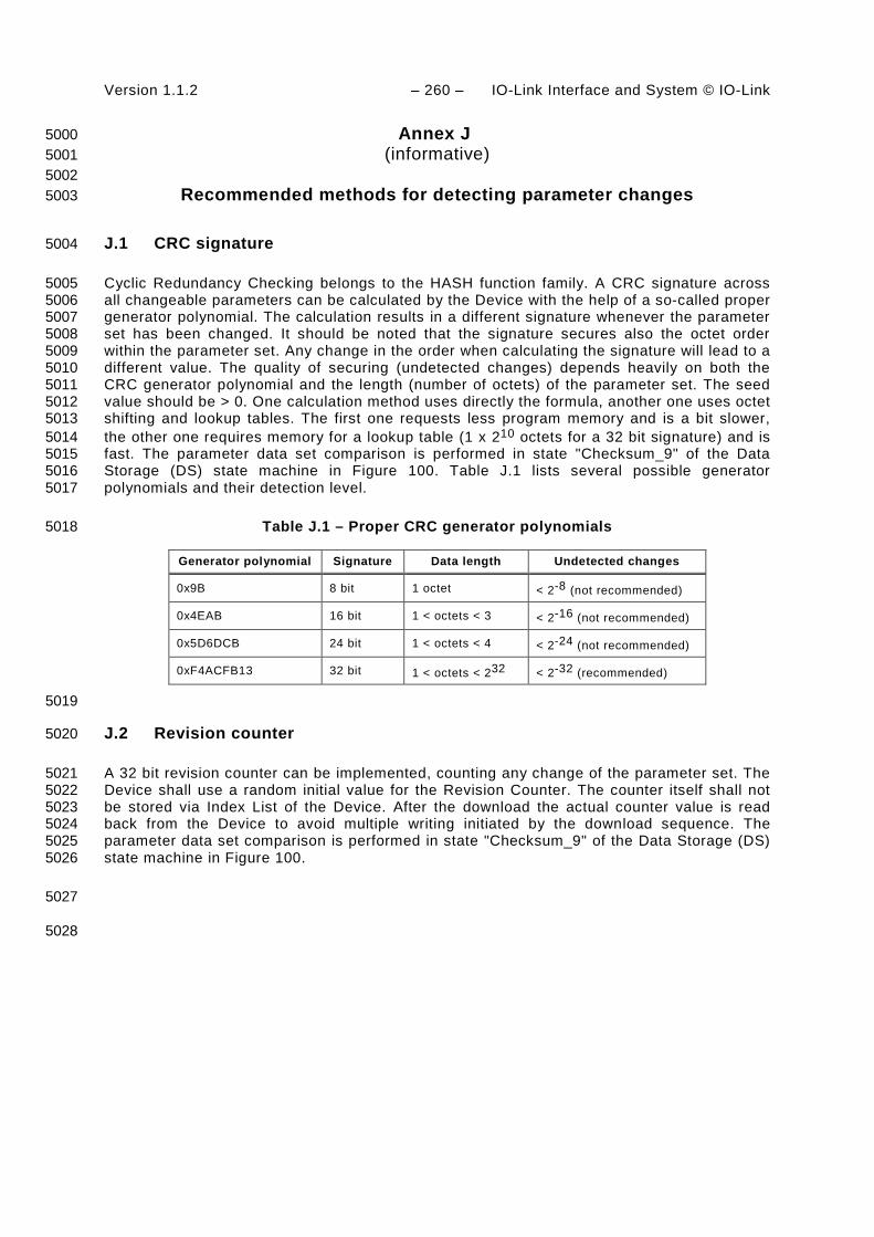
Version 1.1.2 – 260 – IO-Link Interface and System © IO-Link
Annex J 5000 (informative) 5001
5002 Recommended methods for detecting parameter changes 5003
J.1 CRC signature 5004
Cyclic Redundancy Checking belongs to the HASH function family. A CRC signature across 5005 all changeable parameters can be calculated by the Device with the help of a so-called proper 5006 generator polynomial. The calculation results in a different signature whenever the parameter 5007 set has been changed. It should be noted that the signature secures also the octet order 5008 within the parameter set. Any change in the order when calculating the signature will lead to a 5009 different value. The quality of securing (undetected changes) depends heavily on both the 5010 CRC generator polynomial and the length (number of octets) of the parameter set. The seed 5011 value should be > 0. One calculation method uses directly the formula, another one uses octet 5012 shifting and lookup tables. The first one requests less program memory and is a bit slower, 5013 the other one requires memory for a lookup table (1 x 210 octets for a 32 bit signature) and is 5014 fast. The parameter data set comparison is performed in state "Checksum_9" of the Data 5015 Storage (DS) state machine in Figure 100. Table J.1 lists several possible generator 5016 polynomials and their detection level. 5017
Table J.1 – Proper CRC generator polynomials 5018
Generator polynomial Signature Data length Undetected changes
0x9B 8 bit 1 octet < 2-8 (not recommended)
0x4EAB 16 bit 1 < octets < 3 < 2-16 (not recommended)
0x5D6DCB 24 bit 1 < octets < 4 < 2-24 (not recommended)
0xF4ACFB13 32 bit 1 < octets < 232 < 2-32 (recommended)
5019
J.2 Revision counter 5020
A 32 bit revision counter can be implemented, counting any change of the parameter set. The 5021 Device shall use a random initial value for the Revision Counter. The counter itself shall not 5022 be stored via Index List of the Device. After the download the actual counter value is read 5023 back from the Device to avoid multiple writing initiated by the download sequence. The 5024 parameter data set comparison is performed in state "Checksum_9" of the Data Storage (DS) 5025 state machine in Figure 100. 5026
5027
5028

IO-Link Interface and System © IO-Link – 261 – Version 1.1.2
Bibliography 5029
[1] IEC 60050 (all parts), International Electrotechnical Vocabulary, (available at 5030 <http://www.electropedia.org>) 5031
[2] IEC 60870-5-1:1990, Telecontrol equipment and systems – Part 5: Transmission 5032 protocols – Section One: Transmission frame formats 5033
[3] IEC 61158-2, Industrial communication networks – Fieldbus specifications – Part 2: 5034 Physical layer specification and service definition 5035
[4] IEC/TR 62453-61, Field device tool interface specification – Part 61: Device Type 5036 Manager (DTM) Styleguide for common object model 5037
[5] ISO/IEC 7498-1, Information technology – Open Systems Interconnection – Basic 5038 Reference Model: The Basic Model 5039
[6] IO-Link Community, IO Device Description (IODD), V1.1, Order No. 10.012 (available at 5040 <http://www.io-link.com>) 5041
[7] IO-Link Community, IO-Link Smart Sensor Profile, V1.1, Order No. 10.042 (available at 5042 <http://www.io-link.com>) 5043
[8] IO-Link Community, IO-Link Communication, V1.0, January 2009, Order No. 10.002 5044 (available at <http://www.io-link.com>) 5045
[9] IO-Link Community, IO-Link Test Specification, V1.1, Order No. 10.032 (available at 5046 <http://www.io-link.com>) 5047
_____________ 5048

Copyright by:
IO-Link Community Haid-und-Neu-Str. 7 76131 Karlsruhe Germany Phone: +49 (0) 721 / 96 58 590 Fax: +49 (0) 721 / 96 58 589 e-mail: [email protected] http://www.io-link.com/