io-link design guideline€¦ · io-link design guideline v 1.0 page of 32 to )
TRANSCRIPT

IO-Link Design Guideline
www.io-link.com


IO-Link Design Guideline V 1.0
© Copyright PNO 2016 - All Rights Reserved Page 1 of 32
File: IO-Link_Design-Guide_10912_V10_Nov16
Order No.: 10.912
Version: 1.0
Date: November 2016
Published by
IO-Link Firmengemeinschaft (IO-Link Community) c/o PROFIBUS Nutzerorganisation e.V.(PNO) Haid-und-Neu-Str. 7 76131 Karlsruhe Germany Phone: +49 721 / 96 58 590 Fax: +49 721 / 96 58 589 E-mail: [email protected] Web site: www.io-link.com © No part of this publication may be reproduced or utilized in any form or by any means, electronic or mechanical, including photocopying and microfilm, without permission in writing from the publisher.

IO-Link Design Guideline V 1.0
© Copyright PNO 2016 - All Rights Reserved Page 2 of 32
Table of contents
1 Introduction ...................................................................................................................... 5
1.1 Preface ................................................................................................................... 5
1.2 What is IO-Link? ...................................................................................................... 5
1.3 Why is it reasonable to use IO-Link devices instead of normal sensors or actuators? ............................................................................................................... 6
1.4 Target group description.......................................................................................... 7
1.5 Purpose of the design guideline .............................................................................. 7
2 Definition of the system example ...................................................................................... 8
2.1 Technical properties of the devices used in the system example ........................... 12
2.2 Structuring/arrangement of the IO-Link masters .................................................... 16
2.3 Selection of the IO-Link masters ............................................................................ 17
2.4 Planning of the cabling .......................................................................................... 22
2.5 Consideration of the line length, the currents and the voltage drop ........................ 25
2.6 Documentation of the results ................................................................................. 28
3 Summary ........................................................................................................................ 32

IO-Link Design Guideline V 1.0
© Copyright PNO 2016 - All Rights Reserved Page 3 of 32
List of figures
Figure 1: Automation pyramid ................................................................................................. 6
Figure 2: Structure of a conveyor ............................................................................................ 8
Figure 3: Structure of a drive unit ............................................................................................ 9
Figure 4: Conveyor system ................................................................................................... 10
Figure 5: Structure of temperature measurement unit B7 ...................................................... 10
Figure 6: Conveyor system with all sensors and actuators .................................................... 11
Figure 7: General procedure for the selection of components ................................................ 12
Figure 8: Defined connector .................................................................................................. 14
Figure 9: Placement of the IO-Link masters .......................................................................... 17
Figure 10: Connection diagram of the IO-Link master ........................................................... 21
Figure 11: Connection between IO-Link master and IO-Link device of port class A ............... 22
Figure 12: Connection between IO-Link master and IO-Link device of port class B ............... 23
Figure 13: Connection between IO-Link master (port class B) and IO-Link device (port class A) ................................................................................................................................ 24
Figure 14: Setup for the calculation example ........................................................................ 25
Figure 15: Voltage drops ....................................................................................................... 26
Figure 16: Topology of conveyor 1 ........................................................................................ 30
Figure 17: Topology of conveyor 2 ........................................................................................ 31
Figure 18: Topology of conveyors 3 and 4 ............................................................................ 31

IO-Link Design Guideline V 1.0
© Copyright PNO 2016 - All Rights Reserved Page 4 of 32
List of tables
Table 1: Symbols for structuring the text ................................................................................. 5
Table 2: Explanation of the individual designations used in Figure 6. .................................... 11
Table 3: Pin assignment of the connectors ............................................................................ 13
Table 4: Example of device properties .................................................................................. 15
Table 5: Properties of the devices to be connected to conveyor 1 ......................................... 18
Table 6: Properties of the devices to be connected to conveyor 2 ......................................... 19
Table 7: Properties of the devices to be connected to conveyor 3 ......................................... 19
Table 8: Properties of the devices to be connected to conveyor 4 ......................................... 19
Table 9: Advantages and disadvantages of the strategies ..................................................... 20
Table 10: Exemplary technical specifications of the IO-Link master ...................................... 21
Table 11: Overview of possible cabling ................................................................................. 23
Table 12: Exemplary properties for the calculation of the voltage drop .................................. 26
Table 13: Documentation of the IO-Link master assignment .................................................. 29

IO-Link Design Guideline V 1.0
© Copyright PNO 2016 - All Rights Reserved Page 5 of 32
1 Introduction
1.1 Preface
The aim of this IO-Link Design Guideline is to support engineers in planning automation
plants with IO-Link devices. All phases from planning to operation are considered. The
guideline describes the necessary activities in a step-by-step manner using a system
example.
The IO-Link Design Guideline is based on the IO-Link Interface and System Specification
Version 1.1.2 as of July 2013.
For the purpose of improved clarity, symbols are used for structuring the text.
Table 1: Symbols for structuring the text
Symbol Name Meaning
Note
Used to mark a recommendation and/or summary of the
currently described facts.
Important Used for information which, if not observed, may result in
malfunction during operation.
1.2 What is IO-Link?
IO-Link is a serial digital communication protocol intended to be used in automation
technology. It connects sensors or actuators to a programmable logic controller (PLC). In
a way, IO-Link provides for digitalization of the “last metre” of the communication link to
the sensors and actuators. IO-Link is defined in the international standard IEC 61131-9.
Where only binary states (on/off) or analog signals have been transmitted so far, it is
now possible to read status information from a sensor or actuator and write
parameterization information to the sensor or actuator. IO-Link is not just another bus
system, but a point-to-point connection between the IO-Link device and a link device,
namely an IO-Link master.

IO-Link Design Guideline V 1.0
© Copyright PNO 2016 - All Rights Reserved Page 6 of 32
Figure 1: Automation pyramid
The point-to-point connection is set up between an IO-Link master and an IO-Link device
(sensor or actuator) using an unshielded three-core cable. One of the three conductors
is used for communication, one for power supply to the device electronics and one as
the common reference potential. This connection type is called Port Class A in the IO-
Link nomenclature and provides a maximum current output of 200 mA. As actuators
often require an additional actuator power supply, Port Class B is additionally available.
With Port Class B, a shielded five-core cable is used for the connection. Besides the
three conductors already described above, there another two conductors for power
supply to the actuators in this case.
The IO-Link master communicates with the IO-Link devices, collects data from them and
transmits the data to the higher-level bus system. The IO-Link communication protocol
does not include any definitions regarding the higher-level communication protocol.
IO-Link is a communication protocol independent of the bus which
cyclically transmits process data, parameterization data and
diagnostic data from the sensors and actuators via a point-to-point
connection.
1.3 Why is it reasonable to use IO-Link devices instead of normal sensors or actuators?
The use of IO-Link sensors and actuators offers many benefits over digitally switching or
analog sensors and actuators. The IO-Link technology uses serial communication
instead of the linking methods of digital and analog sensors used so far. This
communication method allows for the transmission of parameterization and diagnostic
data to/from the sensor or actuator. The usage of IO-Link decreases the number of

IO-Link Design Guideline V 1.0
© Copyright PNO 2016 - All Rights Reserved Page 7 of 32
different interfaces or connector plugs in your system. Digital communication can lead to
a reduction in system downtimes through predictive maintenance and the parameter
definitions of the IO-Link sensors and actuators can be modified while the system is
operating.
1.4 Target group description
This design guideline is targeted towards experienced readers who are familiar with the
planning and engineering of automation plants, but who are not familiar with IO-Link.
The document is designed to support the readers in getting to know the IO-Link system.
Hence, the most important steps in the planning, engineering and commissioning
process of an automation system with IO-Link components are outlined.
1.5 Purpose of the design guideline
The aim of this guideline is to describe the planning process for an IO-Link system on
the basis of an example. Different types of IO-Link devices are to be used. Therefore, all
required planning steps are explained by means of a notional system.
When using IO-Link devices, in addition to process data, you can
also transmit status information and parameter values.

IO-Link Design Guideline V 1.0
© Copyright PNO 2016 - All Rights Reserved Page 8 of 32
2 Definition of the system example
In the exemplary planning process, a conveyor system is used as an example. There are
different tasks in the conveyor system, which are considered in this document to explain
the planning process. It is assumed that it is already clear which sensors and actuators
are required, and where they will be located.
The following working hypothesis is valid: It shows the intended
location of the selected sensor and actuator.
Figure 2: Structure of a conveyor
Figure 2 shows the basic structure of a conveyor. The entire system consists of several
conveyors. The IO-Link symbol is used to indicate the IO-Link devices. The conveyor
consists of a drive unit M1 and a speed sensor B1. Both components are capable of
communicating with IO-Link. As electric motors cannot be controlled directly via IO-Link,
the structure of a drive unit is illustrated in Figure 3.

IO-Link Design Guideline V 1.0
© Copyright PNO 2016 - All Rights Reserved Page 9 of 32
Figure 3: Structure of a drive unit
A drive unit is made up of three components. The first component is a power contactor
assembly Q11 for a star-delta starting circuit with an IO-Link interface. The second
component is a motor protection switch Q12 connected via an IO-Link interface as well.
The third required component of the drive unit is the motor M11. In order to improve the
clarity of the following figures, only the drive unit of the conveyors is shown in the total
view.
Figure 4 shows the entire conveyor system. The system has a modular structure and
consists of four conveyors. All four conveyors have the same speed sensors B1 to B4
and drive units M1 to M4

IO-Link Design Guideline V 1.0
© Copyright PNO 2016 - All Rights Reserved Page 10 of 32
Figure 4: Conveyor system
As shown in Figure 6, more elements have been added to enhance the conveyors'
functionality. For example, a control unit is mounted on conveyor 1. The control unit is
made up of a push-button switch S1 for starting and stopping the system and a signal
light P1, indicating whether the system is operating. In the area of conveyor 2, a
temperature measurement unit B7 intended for monitoring the ambient temperature is
installed.
Figure 5: Structure of temperature measurement unit B7
As can be seen in Figure 5, the temperature measurement unit B7 consists of an IO-
Link/analog converter B71 and a PT100 resistance temperature detector (RTD)R71.
Additionally, a signal light P2 (see Figure 6) with an IO-Link interface is provided in the
area of conveyor 2 for signaling critical operational states.

IO-Link Design Guideline V 1.0
© Copyright PNO 2016 - All Rights Reserved Page 11 of 32
Figure 6: Conveyor system with all sensors and actuators
A deflector W1 is installed on conveyor 2 to allow for onward transportation of the
material on either conveyor 3 or conveyor 4, as required. An RFID (Radio Frequency
Identifier) sensor B5, an optical distance sensor B6, and a solenoid valve K1 are required
for controlling the deflector. All devices that are needed for the deflector are also
provided with an IO-Link interface. Figure 6 shows the entire conveyor system with all its
sensors and actuators. Table 2 gives an overview of all components installed in the
system.
Table 2: Explanation of the individual designations used in Figure 6.
Designation Type Task IO-Link
B1 – B4 Speed sensors Measure conveyor speed Yes
M1 – M4 Drive unit Drive conveyors Some of
them
B5 RFID sensor Identify conveyed material Yes
B6 Optical distance sensor
Determine deflector position Yes
B7 Temperature measurement unit
Monitor ambient temperature Some of
them
K1 Solenoid valve Pneumatic deflector control Yes
W1 Deflector Guide the conveyed material No
S1 Mech. push-button switch
Start and stop the system No
P1 Signal light, unicolored Signals that the system is operating No
P2 Signal light, multicolored
Signals critical operational states Yes

IO-Link Design Guideline V 1.0
© Copyright PNO 2016 - All Rights Reserved Page 12 of 32
2.1 Technical properties of the devices used in the system example
Various IO-Link sensors and actuators are installed in the system example in Figure 6.
Figure 7 shows in how to proceed with the selection of the IO-Link components.
Figure 7: General procedure for the selection of components
In order to be able to make the electro-technical planning, it is important to determine
the technical properties of the IO-Link devices. Please note that only the system
modules are listed in Table 2 so far. For example, the drive units M1 to M4 consist of
several components each, as can be seen in Figure 3. The temperature measurement
unit B7 is similarly made up of two components (see Figure 5). In the next step, the
technical properties of the IO-Link devices listed below must be determined from the
data sheets of the individual manufacturers.
- IO-Link version
o Which IO-Link version does the device support?
- Port Class
o With which port class is the device connected?
Port class A three-pin with L+, L- (power supply US to sensors and
electronics) and communication channel (C/Q)
Port class B five-pin with L+, L- (US), communication channel (C/Q) ,
2L+ and 2L- (actuator power supply UA)
o Classical (conventional) digital sensors provided with a binary switching
output or actuators controlled via 24 V DC voltage can also be operated on
an IO-Link port. For this purpose, the IO-Link master is configured as a
digital input or output. For example, the mechanical push-button switch S1
and the unicolored pilot light P2 can be connected to an IO-Link port.
- Current consumption of the port class

IO-Link Design Guideline V 1.0
© Copyright PNO 2016 - All Rights Reserved Page 13 of 32
o Port Class A: The maximum current consumption of the device supplied
from voltage US is taken from the data sheet.
o Port Class B: The maximum current consumption of the device supplied
from the voltages US and UA is taken from the data sheet.
o For some devices, the current consumption for US is not always specified.
In this case, a current consumption ≤ 200 mA can be assumed.
- Connector plug
o For an IP67 rated device the connector plugs M5, M8 or M12 are allowed
under the IO-Link specification. It must be determined which connector
type is used on the device. No connector plugs are available for IP20
rating, as usually screw-type or clamp-type connectors are used in this
case.
- Size of the process image
o The size of the process image is not relevant for the electro-technical
planning of the system, but will be required later when choosing the IO-
Link master.
In the data sheets of the IO-Link devices, you can often find terminal diagrams. In order
to enable you to take the required information from these diagrams, the individual
connectors and their pin assignments are shown in Table 3 and in Figure 8.
Table 3: Pin assignment of the connectors
Pin Signal Description Core color1
1 L+ 24 V power supply (US+) brown
2
I/Q
not connected (port class A)
DI – digital input (port class A)
DO – digital output (port class A)
white
2L+ extra power supply (UA+) (port class B) not defined
3 L- 24 V power supply (US-) blue
4 C/Q SIO standard input/output or IO-Link
communication black
5
NC not connected (port class A)
2L- extra power supply (UA-) (port class B) not defined
————————— 1 Acc. to IEC 60947-5-2 for four-pin connectors

IO-Link Design Guideline V 1.0
© Copyright PNO 2016 - All Rights Reserved Page 14 of 32
Figure 8: Defined connector
The IO-Link specification defines the port class B only for M12
connectors. It is nevertheless possible to operate IO-Link devices of
port class B on IO-Link masters with IP20 rating by freely assigning
the terminals. In this case, the additional supply voltage is realized
by using a terminal block.
It is recommended to use a table similar to Table 4 for collecting this information.

IO-Link Design Guideline V 1.0
© Copyright PNO 2016 - All Rights Reserved Page 15 of 32
Table 4: Example of device properties
Designation Type IO-Link
version
Port
class
Current
consumption
form voltage US
Current
consumption
form voltage UA
Connector
type
Size of
process
image
In/Out
B1 – B4 Speed sensor V1.1 A 50 mA - M12 4/0 bytes
Q11, Q21
Q31, Q41
Contactors of
drive units V1.1 B n.a. (≤200 mA) 250 mA IP20 2/2 bytes
Q12, Q22
Q32, Q43
Motor protector of
drive units V1.1 A 5 mA - IP20 4/2 bytes
B5 RFID sensor V1.0 A 50 mA - M12 8/8 bytes
B6 Light push-button
switch V1.0 A 70 mA - M12 2/0 bytes
B71 IO-Link/analog
converter V1.1 A 25 mA - M12 2/2 bytes
K1 Solenoid valve V1.0 B 3 mA 400 mA M12 4/6 bytes
P2 Signal light
multicolored V1.1 A 410 mA - M12 1/8 bytes
S1 Mech. push-
button switch - DI - - IP20 1/0 bits
P1 Signal light
unicolored - DO 150 mA through pin 4 (C/Q) IP20 0/1 bits

IO-Link Design Guideline V 1.0
© Copyright PNO 2016 - All Rights Reserved Page 16 of 32
2.2 Structuring/arrangement of the IO-Link masters
The IO-Link devices considered so far now have to be connected to an IO-Link master.
The master receives the process values from the sensors; these process values are
aggregated in the master and transmitted to the higher-level bus system. In the case of
an IO-Link actuator, the process value is received from the higher-level bus system and
transmitted to the actuator. An IO-Link master can operate only a limited number of IO-
Link devices. As a result, several IO-Link masters are normally used. In the following
section the number of IO-Link masters is determined and where they will be placed in
the system example. Care must be taken to ensure that the maximum line length of 20 m
between the IO-Link master and the IO-Link devices defined in the IO-Link specification
is not exceeded. Due to these limitations, several IO-Link masters are used in the
example. Placing a single master in a central position would result in line lengths of
more than 20 m.
If you take a closer look at the conveyor system, you will recognize its modular structure.
The control panel on conveyor 1 could be allocated to any of the conveyors. Also, the
deflector with its sensors and actuators could be considered as an enhancement of an
existing conveyor. The modular structure of this system reduces the production costs as
the “same” basic conveyor is reused. In this modular system the individual conveyors
can be combined to form a conveyor line and could be enhanced with additional
components if required. In order to preserve this modularity, a separate IO-Link master
is planned for each conveyor in our system example.
IO-Link Design Guideline V 1.0
© Copyright PNO 2016 - All Rights Reserved Page 17 of 32
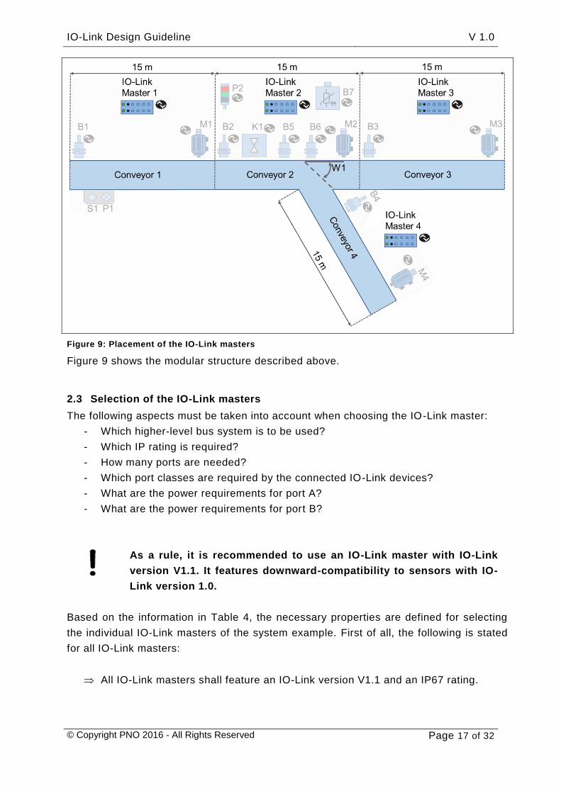
Figure 9: Placement of the IO-Link masters
Figure 9 shows the modular structure described above.
2.3 Selection of the IO-Link masters
The following aspects must be taken into account when choosing the IO-Link master:
- Which higher-level bus system is to be used?
- Which IP rating is required?
- How many ports are needed?
- Which port classes are required by the connected IO-Link devices?
- What are the power requirements for port A?
- What are the power requirements for port B?
As a rule, it is recommended to use an IO-Link master with IO-Link
version V1.1. It features downward-compatibility to sensors with IO-
Link version 1.0.
Based on the information in Table 4, the necessary properties are defined for selecting
the individual IO-Link masters of the system example. First of all, the following is stated
for all IO-Link masters:
All IO-Link masters shall feature an IO-Link version V1.1 and an IP67 rating.
IO-Link Design Guideline V 1.0
© Copyright PNO 2016 - All Rights Reserved Page 18 of 32
In the next steps, more specifications are made. For this purpose, the properties of the
connected devices are collected in the following tables for each of the planned
conveyors.
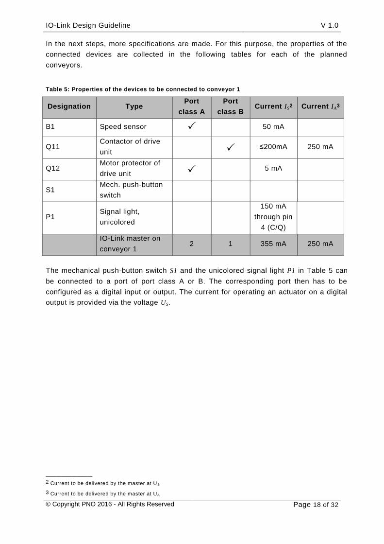
Table 5: Properties of the devices to be connected to conveyor 1
Designation Type Port
class A
Port
class B Current IS
2 Current IA3
B1 Speed sensor 50 mA
Q11 Contactor of drive
unit ≤200mA 250 mA
Q12 Motor protector of
drive unit 5 mA
S1 Mech. push-button
switch
P1 Signal light,
unicolored
150 mA
through pin
4 (C/Q)
IO-Link master on
conveyor 1 2 1 355 mA 250 mA
The mechanical push-button switch S1 and the unicolored signal light P1 in Table 5 can
be connected to a port of port class A or B. The corresponding port then has to be
configured as a digital input or output. The current for operating an actuator on a digital
output is provided via the voltage US.
————————— 2 Current to be delivered by the master at US
3 Current to be delivered by the master at UA

IO-Link Design Guideline V 1.0
© Copyright PNO 2016 - All Rights Reserved Page 19 of 32
Table 6: Properties of the devices to be connected to conveyor 2
Designation Type Port
class A
Port
class B Current IS Current IA
B2 Speed sensor 50 mA
Q21 Contactor of drive
unit ≤200mA 250 mA
Q22 Motor protector of
drive unit 5 mA
B5 RFID sensor 50 mA
B6 Optical distance
sensor 70 mA
B71 IO-Link/analog
converter 25 mA
K1 Solenoid valve 3 mA 400 mA
P1 Signal light 410 mA
IO-Link master on
conveyor 2 6 2 813 mA 650 mA
Table 7: Properties of the devices to be connected to conveyor 3
Designation Type Port
class A
Port
class B Current IS Current IA
B3 Speed sensor 50 mA
Q31 Contactor of drive
unit ≤200mA 250 mA
Q32 Motor protector of
drive unit 5 mA
IO-Link master on
conveyor 3 2 1 255 mA 250 mA
Table 8: Properties of the devices to be connected to conveyor 4
Designation Type Port
class A
Port
class B Current IS Current IA
B4 Speed sensor 50 mA
Q41 Contactor of drive
unit ≤200mA 250 mA
Q42 Motor protector of
drive unit 5 mA
IO-Link master on
conveyor 4 2 1 255 mA 250 mA

IO-Link Design Guideline V 1.0
© Copyright PNO 2016 - All Rights Reserved Page 20 of 32
Based on the requirements of the IO-Link masters in Table 5 to Table 8 it is now
possible to select IO-Link masters from different manufacturers. The competence matrix
of the IO-Link Community on the home page www.io-link.com provides an overview of
the manufacturers. IO-Link masters are available for many higher-level bus systems and
with various port configurations. There are IO-Link masters with only port class A or port
class B ports or IO-Link masters that support both port class A and port class B. As there
is a wide range of IO-Link masters, the present design guideline cannot describe all
possible variants.
Prior to choosing a master, you first have to decide which strategy is to be pursued.
1. Strategy 1: use of a single IO-Link master type
This single IO-Link master type would have to meet the maximum requirements
(in this example the IO-Link master on conveyor 2), but would be over-specified
for the other applications.
2. Strategy 2: use of a various different IO-Link master types
In this case, IO-Link masters of different types tailored to the needs of the
corresponding (conveyor) application would be used.
Table 9: Advantages and disadvantages of the strategies
Advantages Disadvantages
Strategy 1
- Low expenditure of time for
planning
- Easy procurement and spare
parts supply (only one IO-Link
master type needed)
- No likelihood of confusion
(identical masters on all
conveyors)
- Identical structures of all
conveyors
- Higher costs, as some of the
masters will be over-specified.
Strategy 2
- More cost-effective procurement,
as better suited components are
used
- Different structures of the
individual conveyors
- Higher expenditure of time for
planning
- More complex procurement and
spare parts supply (several IO-Link
master types needed)
- Danger of confusion (different IO-
Link masters on the individual
conveyors)
IO-Link Design Guideline V 1.0
© Copyright PNO 2016 - All Rights Reserved Page 21 of 32
From this point on, strategy 1 will be pursued for the planning process. A notional IO-
Link master is used for this purpose. Upon selection of the IO-Link master you have to
verify the technical properties. The verification basically consists of comparing the rated
currents of the IO-Link masters with the determined currents in Table 5 to Table 8.
Table 10: Exemplary technical specifications of the IO-Link master
Number of ports of port class A Number of ports of port class B
- 8 ports
Rated current
Pins 1 and 3
Rated current
Pin 4 (C/Q)
Rated current
Pins 2 and 5
200 mA 150 mA Max. total current of 3.5 A across all
ports Max. 1.6 A across all 8 C/Q and L+ lines
IO-Link devices have a maximum process image of 32 bytes. Not all
of the IO-Link masters can transmit 32 bytes per port to the higher-
level bus system. Check the manufacturer documentation on this.
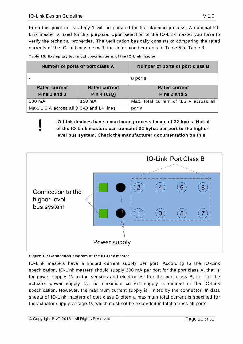
Figure 10: Connection diagram of the IO-Link master
IO-Link masters have a limited current supply per port. According to the IO-Link
specification, IO-Link masters should supply 200 mA per port for the port class A, that is
for power supply US to the sensors and electronics. For the port class B, i.e. for the
actuator power supply UA, no maximum current supply is defined in the IO-Link
specification. However, the maximum current supply is limited by the connector. In data
sheets of IO-Link masters of port class B often a maximum total current is specified for
the actuator supply voltage UA which must not be exceeded in total across all ports.

IO-Link Design Guideline V 1.0
© Copyright PNO 2016 - All Rights Reserved Page 22 of 32
If you compare the rated currents in Table 10 with the specifications in Table 5 to Table
8, you will recognize that the selected IO-Link master will deliver a sufficient current in
all configurations.
However, there are IO-Link devices on the market which require more
than 200 mA from the sensor and actuator power supply. These
devices cannot be operated on any IO-Link master. In this case
please check the IO-Link master's data sheet to see if it is capable of
delivering the correspondingly higher current.
For our system example we assume that the signal light P1 works properly on the
selected IO-Link master despite the fact that the standard is disregarded.
2.4 Planning of the cabling
Once the system structure has been determined and the IO-Link devices and IO-Link
masters have been defined, the cabling is planned in the next step.
This primarily involves the connection between the IO-Link master and its IO-Link
devices. For port class A a three-core unshielded control line is sufficient for cabling. In
practice, however, you will frequently find four-core unshielded control lines instead as
they are more available than three-core lines.
Figure 11: Connection between IO-Link master and IO-Link device of port class A
Figure 11 shows the connection between an IO-Link master of port class A and an IO-
Link device of port class A. When using a three-core cable, the pins 1, 3 and 4 are
interconnected. With this, proper functioning of the device is already g iven. If a four-core
cable is used, the pin 2 connections at each end should be interconnected to each other
as shown. Although this is permissible, you should make sure that pin 2 of an IO-Link
master of port class A is not being used or configured as a digital input.
IO-Link Design Guideline V 1.0
© Copyright PNO 2016 - All Rights Reserved Page 23 of 32
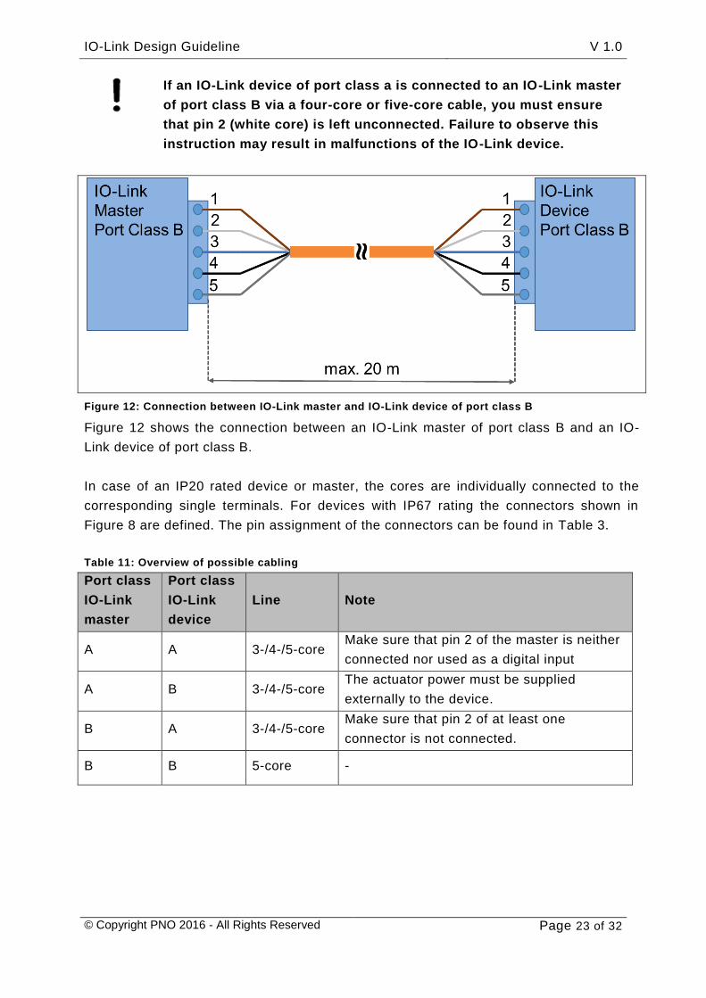
Figure 12: Connection between IO-Link master and IO-Link device of port class B
Figure 12 shows the connection between an IO-Link master of port class B and an IO-
Link device of port class B.
In case of an IP20 rated device or master, the cores are individually connected to the
corresponding single terminals. For devices with IP67 rating the connectors shown in
Figure 8 are defined. The pin assignment of the connectors can be found in Table 3.
Table 11: Overview of possible cabling
Port class
IO-Link
master
Port class
IO-Link
device
Line Note
A A 3-/4-/5-core Make sure that pin 2 of the master is neither
connected nor used as a digital input
A B 3-/4-/5-core The actuator power must be supplied
externally to the device.
B A 3-/4-/5-core Make sure that pin 2 of at least one
connector is not connected.
B B 5-core -
If an IO-Link device of port class a is connected to an IO-Link master
of port class B via a four-core or five-core cable, you must ensure
that pin 2 (white core) is left unconnected. Failure to observe this
instruction may result in malfunctions of the IO-Link device.

IO-Link Design Guideline V 1.0
© Copyright PNO 2016 - All Rights Reserved Page 24 of 32
When using a safety-related emergency stop function through the
master of port class B, the simultaneous operation of devices of port
class A and port class B must be considered separately.
Figure 13: Connection between IO-Link master (port class B) and IO-Link device (port class A)
It is prohibited to connect an IO-Link master of port class B to an IO-Link device of port
class B through a five-core cable, as shown in Figure 13, as this would disable a
potentially configured emergency stop function. Normally, actuating the emergency stop
button will cut off the actuator supply voltage (pin 2) at the IO-Link master of port class B
and de-energize the load circuits of the IO-Link actuators of port class B connected to
the master (emergency stop function). If an IO-Link master of port class B and an IO-
Link device of port class A are connected via a five-core cable, it may happen under
special circumstances that a switch contact occurs in the circuit between pin 1 and pin 2,
as shown in Figure 13. When this contact is closed, the sensor supply voltage across pin
1 is bridged to the actuator supply voltage across pin 2, hence causing inadvertent
power supply to the actuator load circuits. In this configuration, the emergency stop
function will not work.

IO-Link Design Guideline V 1.0
© Copyright PNO 2016 - All Rights Reserved Page 25 of 32
2.5 Consideration of the line length, the currents and the voltage drop
When planning the cabling, make sure that the maximum cable
length between the IO-Link master and an IO-Link device does not
exceed 20 m.
Regarding the power supply, you also have to make sure that a sufficient supply voltage
is available at the device. As a voltage drop occurs along every supply cable, the entire
cable route from the power supply unit to the IO-Link device must be taken into account.
Figure 14 and Figure 15 illustrate this topic. In the following, the voltage drops along a
supply cable, from the power supply unit through the IO-Link master to the IO-Link
device, are determined in an exemplary manner. For an IO-Link master of port class B,
the voltage drop must be calculated separately for each of the two supply voltages (US
and UA).
If the currents of the IO-Link devices are lower than 200 mA, a cable
with a core cross-sectional area of 0.35 mm² and a length of up to
20 m can be used to connect the IO-Link master and IO-Link device.
No special calculation is required in this case.
Nevertheless, the supply cables between the power supply unit and
the IO-Link master should be checked for voltage drops.
Figure 14: Setup for the calculation example
Figure 14 shows an exemplary setup to be used as a basis for calculating the voltage
drop along the supply cables. The power supply unit provides a voltage of 24 V across
its output. The power is supplied via a cable to the IO-Link master and from there to

IO-Link Design Guideline V 1.0
© Copyright PNO 2016 - All Rights Reserved Page 26 of 32
the IO-Link device and the IO-Link device . It is to be expected that voltage drops in
relation to the initial supply voltage will occur along the cables , and . For further
calculations we assume the cable and device properties described in Table 12.
Table 12: Exemplary properties for the calculation of the voltage drop
Description Properties
1 Power supply unit Rated voltage 24 V DC ±1% tolerance
2 Control line
Power supply IO-Link master
Length: 10 m
Core cross-sectional area: 0.75 mm²
3 IO-Link master Voltage drop: 0.5 V
Rated current: 100 mA
4 Control line
IO-Link master IO-Link device 1
Length: 15 m
Core cross-sectional area: 0.35 mm²
5 IO-Link device 1 Rated current: 200 mA
Rated voltage: 19 to 30 V
6 Control line
IO-Link master IO-Link device 2
Length: 15 m
Core cross-sectional area: 0.35 mm²
7 IO-Link device 2 Rated current: 100 mA
Rated voltage: 19 to 30 V
Based on this assumption, the calculation of the voltage drop from the power supply unit
to the IO device according to Figure 15 is explained in the following section.
Figure 15: Voltage drops

IO-Link Design Guideline V 1.0
© Copyright PNO 2016 - All Rights Reserved Page 27 of 32
Item 1 in Figure 15 is the “starting point” of the calculation. For the consideration of the
voltage drop, a “worst-case” calculation should be performed. As a result, the low (min.)
limit value of the supply voltage (24 𝑉 ∙ (100% − 1%) = 23.76 𝑉) at the power supply unit is
assumed in the first step.
For determining the voltage drop across the line between the power supply unit and
the IO-Link master (see Figure 15), first of all the total line current IL1 is needed. The
total line current results from the sum of all rated currents of the connected devices
and and the rated current of the IO-Link master (see equation 1).
𝐼𝐿1 = 𝐼𝑀 + 𝐼𝐷1 + 𝐼𝐷2 = 100 𝑚𝐴 + 200 𝑚𝐴 + 100 𝑚𝐴 = 400 𝑚𝐴 = 0.4 𝐴 1
Based on the result of equation 1, the voltage drop can be determined by means of
equations 2 to 4.
𝑈 = 𝑅𝐿 ∙ 𝐼 2
𝑈 = 𝑅𝐵 ∙ 2 ∙ 𝑙 ∙ 𝐼 3
𝑈 = 𝜌 ∙2 ∙ 𝑙
𝐴∙ 𝐼 4
𝑈: 𝑉𝑜𝑙𝑡𝑎𝑔𝑒 𝑑𝑟𝑜𝑝 𝑎𝑙𝑜𝑛𝑔 𝑙𝑖𝑛 𝑖𝑛 𝑉
𝑅𝐿: 𝐿𝑖𝑛𝑒 𝑟𝑒𝑠𝑖𝑠𝑡𝑎𝑛𝑐𝑒 𝑖𝑛 Ω
𝑅𝐵: 𝑅𝑒𝑠𝑖𝑠𝑡𝑎𝑛𝑐𝑒 𝑐𝑜𝑒𝑓𝑓𝑖𝑐𝑖𝑒𝑛𝑡 𝑜𝑓 𝑙𝑖𝑛𝑒 Ω𝑚⁄
𝜌: 𝑆𝑝𝑒𝑐𝑖𝑓𝑖𝑐 𝑟𝑒𝑠𝑖𝑠𝑡𝑎𝑛𝑐𝑒 𝑜𝑓 𝑙𝑖𝑛𝑒 𝑚𝑎𝑡𝑒𝑟𝑖𝑎𝑙
𝐿𝑖𝑛𝑒 𝑐𝑜𝑝𝑝𝑒𝑟 𝜌 = 1.69 … 1.75 ∙ 10−2Ω𝑚𝑚2
𝑚
𝑙: 𝐿𝑖𝑛𝑒 𝑙𝑒𝑛𝑔𝑡ℎ 𝑖𝑛 𝑚
𝐴: 𝐶𝑜𝑟𝑒 𝑐𝑟𝑜𝑠𝑠– 𝑠𝑒𝑐𝑡𝑖𝑜𝑛𝑎𝑙 𝑎𝑟𝑒𝑎 𝑖𝑛 𝑚𝑚²
𝐼: 𝐿𝑖𝑛𝑒 𝑐𝑢𝑟𝑟𝑒𝑛𝑡 𝐴
From equation 4 and the technical cable specifications results a voltage drop of 100 mV
along line . Hence, a voltage of 23.77 𝑉 – 0.1 𝑉 = 23.66 𝑉 is applied to the IO-Link
master.
At item in Figure 15 you can see the voltage drop in the IO-Link master. The voltage
drop occurs between the supply point and the ports of the IO-Link master. If this value is
not specified in the IO-Link master's data sheet, an internal voltage drop of 0.5 V can be
assumed. Across the ports for connecting the IO-Link devices a voltage of
23.66 𝑉 – 0.5 𝑉 = 23.16 𝑉 is now available.

IO-Link Design Guideline V 1.0
© Copyright PNO 2016 - All Rights Reserved Page 28 of 32
Equation 4 is used again to calculate the voltage drops along the lines and . The
current I in the lines is equal to the rated current of the connected IO-Link devices and
.
From this results a voltage drop of 150 mV along the line . Hence, a voltage of
23,16 𝑉 – 0,15 𝑉 = 23,01 𝑉 is applied to the IO-Link device . This voltage is sufficient for
the IO-Link device (see rated voltage range specified in Table 12).
The voltage drop along the line is 90 mV. Hence, a voltage of 23,16 𝑉 – 0,09 𝑉 =
23,07 𝑉 is applied to the IO-Link device . This voltage is also sufficient for the IO-Link
device (see rated voltage range specified in Table 12).
The voltages US and UA must be considered separately when
calculating the voltage drop.
Besides this, only the usual provisions for cable laying, for example
regarding cable segregation, the protection against damage and the
adherence to the minimum bending radii, must be observed.
2.6 Documentation of the results
When all relevant issues of the hardware-related planning process have been
completed, the results must be documented accordingly. The documentation should
comprise the following elements:
- Table 4: Example of device properties
- Table 10: Exemplary technical specifications of the IO-Link master
- Table 13: Documentation of the IO-Link master assignment
- Figure 16: Topology of conveyor 1
- Figure 17: Topology of conveyor 2
- Figure 18: Topology of conveyors 3 and 4
- Data sheets of the IO-Link devices and the IO-Link master.
Table 13 indicates the IO-Link device allocation to the ports of the IO-Link masters.

IO-Link Design Guideline V 1.0
© Copyright PNO 2016 - All Rights Reserved Page 29 of 32
Table 13: Documentation of the IO-Link master assignment
IO-Link master Port
number
Port
class Device
Parameter
setting
IO-Link master 1
Conveyor 1
1 B B1 – Speed sensor IO-Link
2 B Q12 – Motor protection switch IO-Link
3 B S1 – Mech. push-button switch Digital input
4 B Q11 – Power contactor - IO-Link
5 B P1 – Signal light - Digital output
6 B - deactivated
7 B - deactivated
8 B - deactivated
IO-Link master 2
Conveyor 2
1 B B3 – Speed sensor IO-Link
2 B Q32 – Motor protection switch IO-Link
3 B B5 – RFID sensor IO-Link
4 B B6 – Optical distance sensor IO-Link
5 B P2 – Signal light IO-Link
6 B Q32 – Power contactor IO-Link
7 B K1 – Solenoid valve IO-Link
8 B B71 – IO-Link/analog
converter IO-Link
IO-Link master 3
Conveyor 3
1 B B3 – Speed sensor IO-Link
2 B Q32 – Motor protection switch IO-Link
3 B Q32 – Power contactor IO-Link
4 B - deactivated
5 B - deactivated
6 B - deactivated

IO-Link Design Guideline V 1.0
© Copyright PNO 2016 - All Rights Reserved Page 30 of 32
7 B - deactivated
8 B - deactivated
IO-Link master 4
Conveyor 4
1 B B4 – Speed sensor IO-Link
2 B Q42 – Motor protection switch IO-Link
3 B Q42 – Power contactor IO-Link
4 B - deactivated
5 B - deactivated
6 B - deactivated
7 B - deactivated
8 B - deactivated
In the following section, Figure 16 to Figure 18 illustrate the cabling of the individual
conveyor segments.
Figure 16: Topology of conveyor 1

IO-Link Design Guideline V 1.0
© Copyright PNO 2016 - All Rights Reserved Page 31 of 32
Figure 17: Topology of conveyor 2
Figure 18: Topology of conveyors 3 and 4

IO-Link Design Guideline V 1.0
© Copyright PNO 2016 - All Rights Reserved Page 32 of 32
3 Summary
This IO-Link Design Guideline is intended to familiarize the readers by means of action-
oriented explanations with the planning and engineering of an automation system with
IO-Link components. An exemplary model system helps to explain the difficulties that
may arise in the course of the electrical engineering process and develop solutions for
these problems.
IO-Link Design GuidelineVersion November 2016
Order No.: 10.912
Publisher
IO-Link Community c/o PROFIBUS Nutzerorganisation e.V. (PNO) Haid-und-Neu-Str. 7 76131 Karlsruhe Germany
Phone: +49 721 96 58 590 Fax: +49 721 96 58 589 E-Mail: [email protected] Internet: www.io-link.com
Exclusion of liability
IO-Link Company Community has examined the contents of this brochure carefully. Nevertheless, errors can not be excluded. Liability of IO-Link Company Community is excluded, regardless of the reason. The data in this brochure is checked periodically, however. Necessary corrections will be contained in subsequent versions. We gratefully accept suggestions for improvement.
Terms used in this brochure may be trade marks and their use by third parties for any purposes may violate the rights of the owner.**
This brochure is not a substitute for the respective IEC standards and the IO-Link specifications and profiles. In case of doubt, these documents take precendence.
© Copyright by PROFIBUS Nutzerorganisation e.V. 2016. All rights reserved.
** ® is a registered trademark. It may be used only by the members of the IO-Link Community and non-members who had acquired the corresponding license. For more detailed information on its use, refer to the rules of the IO-Link Community at www.io-link.com.

IO-Link Community c/o PROFIBUS Nutzerorganisation e. V. (PNO)Haid-und-Neu-Str. 7 | 76131 Karlsruhe | GermanyPhone: +49 721 96 58 590 | Fax: +49 721 96 58 589E-Mail: germany@profi bus.comwww.io-link.com
More Informationen:www.io-link.com