i/o, disks, and raid. 2 goals for today review i/o –how does a computer system interact with its...
Post on 22-Dec-2015
216 views
TRANSCRIPT

I/O, Disks, and RAID

2
Goals for Today
• Review I/O– How does a computer system interact with its environment?
• Disks– How does a computer system permanently store data?
• Prelim graded!– Discuss and pass back today
• RAID– How to make storage both efficient and reliable?
3
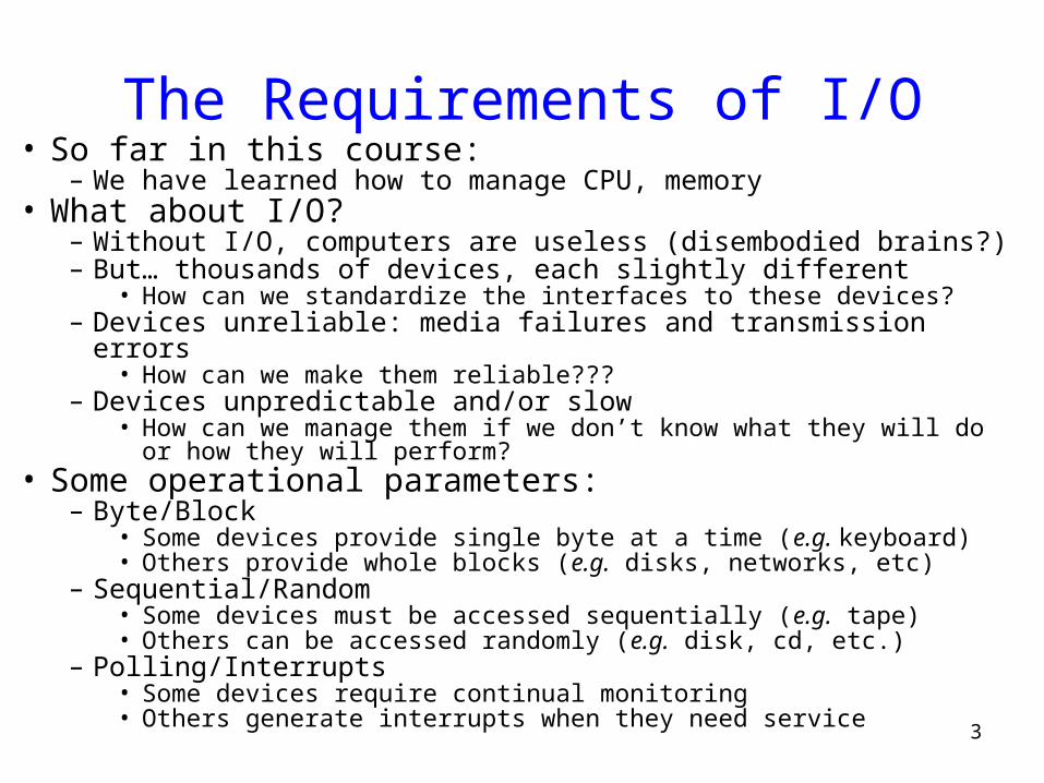
The Requirements of I/O• So far in this course:
– We have learned how to manage CPU, memory• What about I/O?
– Without I/O, computers are useless (disembodied brains?)– But… thousands of devices, each slightly different
• How can we standardize the interfaces to these devices?– Devices unreliable: media failures and transmission errors
• How can we make them reliable???– Devices unpredictable and/or slow
• How can we manage them if we don’t know what they will do or how they will perform?
• Some operational parameters:– Byte/Block
• Some devices provide single byte at a time (e.g. keyboard)• Others provide whole blocks (e.g. disks, networks, etc)
– Sequential/Random• Some devices must be accessed sequentially (e.g. tape)• Others can be accessed randomly (e.g. disk, cd, etc.)
– Polling/Interrupts• Some devices require continual monitoring• Others generate interrupts when they need service

4
Modern I/O Systems
5
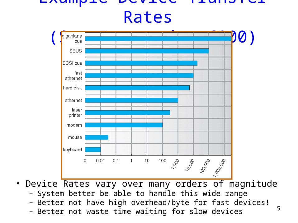
Example Device-Transfer Rates (Sun Enterprise 6000)
• Device Rates vary over many orders of magnitude– System better be able to handle this wide range– Better not have high overhead/byte for fast devices!– Better not waste time waiting for slow devices
6
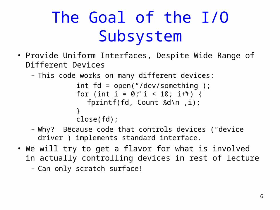
The Goal of the I/O Subsystem
• Provide Uniform Interfaces, Despite Wide Range of Different Devices
– This code works on many different devices:
int fd = open(“/dev/something”);for (int i = 0; i < 10; i++) {
fprintf(fd,”Count %d\n”,i);}close(fd);
– Why? Because code that controls devices (“device driver”) implements standard interface.
• We will try to get a flavor for what is involved in actually controlling devices in rest of lecture
– Can only scratch surface!

7
Want Standard Interfaces to Devices• Block Devices: e.g. disk drives, tape drives, DVD-ROM
– Access blocks of data– Commands include open(), read(), write(), seek()– Raw I/O or file-system access– Memory-mapped file access possible
• Character Devices: e.g. keyboards, mice, serial ports, some USB devices
– Single characters at a time– Commands include get(), put()– Libraries layered on top allow line editing
• Network Devices: e.g. Ethernet, Wireless, Bluetooth– Different enough from block/character to have own interface– Unix and Windows include socket interface
• Separates network protocol from network operation• Includes select() functionality
– Usage: pipes, FIFOs, streams, queues, mailboxes
8
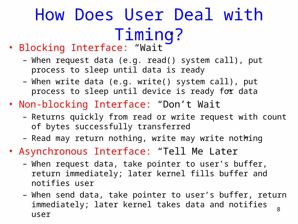
How Does User Deal with Timing?• Blocking Interface: “Wait”
– When request data (e.g. read() system call), put process to sleep until data is ready
– When write data (e.g. write() system call), put process to sleep until device is ready for data
• Non-blocking Interface: “Don’t Wait”– Returns quickly from read or write request with count of bytes
successfully transferred– Read may return nothing, write may write nothing
• Asynchronous Interface: “Tell Me Later”– When request data, take pointer to user’s buffer, return immediately;
later kernel fills buffer and notifies user– When send data, take pointer to user’s buffer, return immediately;
later kernel takes data and notifies user
9
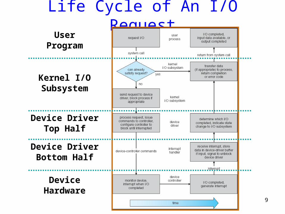
Life Cycle of An I/O Request
Device DriverTop Half
Device DriverBottom Half
DeviceHardware
Kernel I/OSubsystem
UserProgram
10
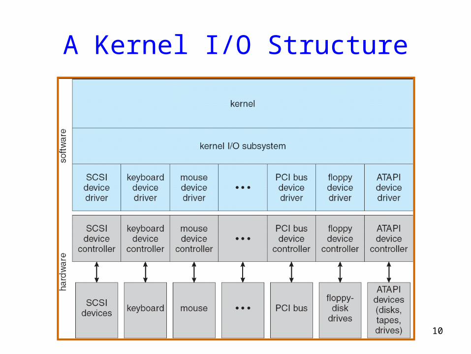
A Kernel I/O Structure
11
Device Drivers
• Device Driver: Device-specific code in the kernel that interacts directly with the device hardware
– Supports a standard, internal interface– Same kernel I/O system can interact easily with different device
drivers– Special device-specific configuration supported with the ioctl()
system call• Device Drivers typically divided into two pieces:
– Top half: accessed in call path from system calls• Implements a set of standard, cross-device calls like open(), close(), read(), write(), ioctl(), strategy()
• This is the kernel’s interface to the device driver• Top half will start I/O to device, may put thread to sleep until finished
– Bottom half: run as interrupt routine• Gets input or transfers next block of output• May wake sleeping threads if I/O now complete

12
I/O Device Notifying the OS• The OS needs to know when:
– The I/O device has completed an operation– The I/O operation has encountered an error
• I/O Interrupt:– Device generates an interrupt whenever it needs service– Pro: handles unpredictable events well– Con: interrupts relatively high overhead
• Polling:– OS periodically checks a device-specific status register
• I/O device puts completion information in status register• Could use timer to invoke lower half of drivers occasionally
– Pro: low overhead– Con: may waste many cycles on polling if infrequent or unpredictable
I/O operations• Some devices combine both polling and interrupts
– For instance: High-bandwidth network device: • Interrupt for first incoming packet• Poll for following packets until hardware empty
13
DeviceController
readwrite
controlstatus
AddressableMemoryand/orQueuesRegisters
(port 0x20)
HardwareController
Memory MappedRegion: 0x8f008020
BusInterface
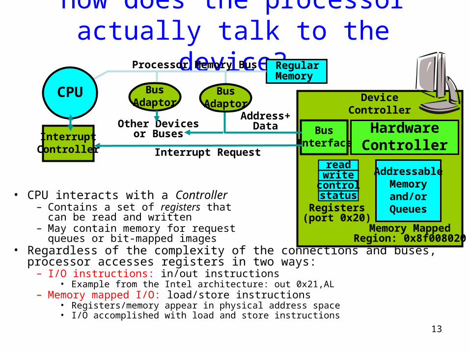
How does the processor actually talk to the device?
• CPU interacts with a Controller– Contains a set of registers that
can be read and written– May contain memory for request
queues or bit-mapped images • Regardless of the complexity of the connections and buses, processor accesses
registers in two ways: – I/O instructions: in/out instructions
• Example from the Intel architecture: out 0x21,AL– Memory mapped I/O: load/store instructions
• Registers/memory appear in physical address space• I/O accomplished with load and store instructions
Address+Data
Interrupt Request
Processor Memory Bus
CPU
RegularMemory
InterruptController
BusAdaptor
BusAdaptor
Other Devicesor Buses

14
Transfering Data To/From Controller• Programmed I/O:
– Each byte transferred via processor in/out or load/store– Pro: Simple hardware, easy to program– Con: Consumes processor cycles proportional to data size
• Direct Memory Access:– Give controller access to memory bus– Ask it to transfer data to/from memory directly
• Sample interaction with DMA controller (from book):

15
Main components of Intel Chipset: Pentium 4
• Northbridge:– Handles memory– Graphics
• Southbridge: I/O– PCI bus– Disk controllers– USB controllers– Audio– Serial I/O– Interrupt controller– Timers
16
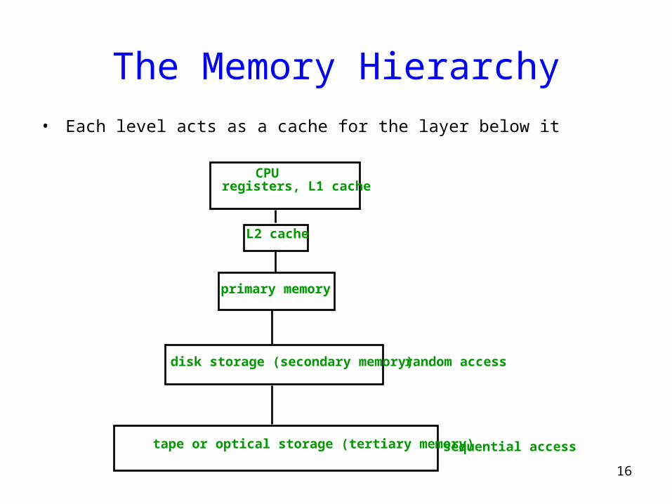
The Memory Hierarchy• Each level acts as a cache for the layer below it
CPUregisters, L1 cache
L2 cache
primary memory
disk storage (secondary memory)
tape or optical storage (tertiary memory)
random access
sequential access

Disks
17
18
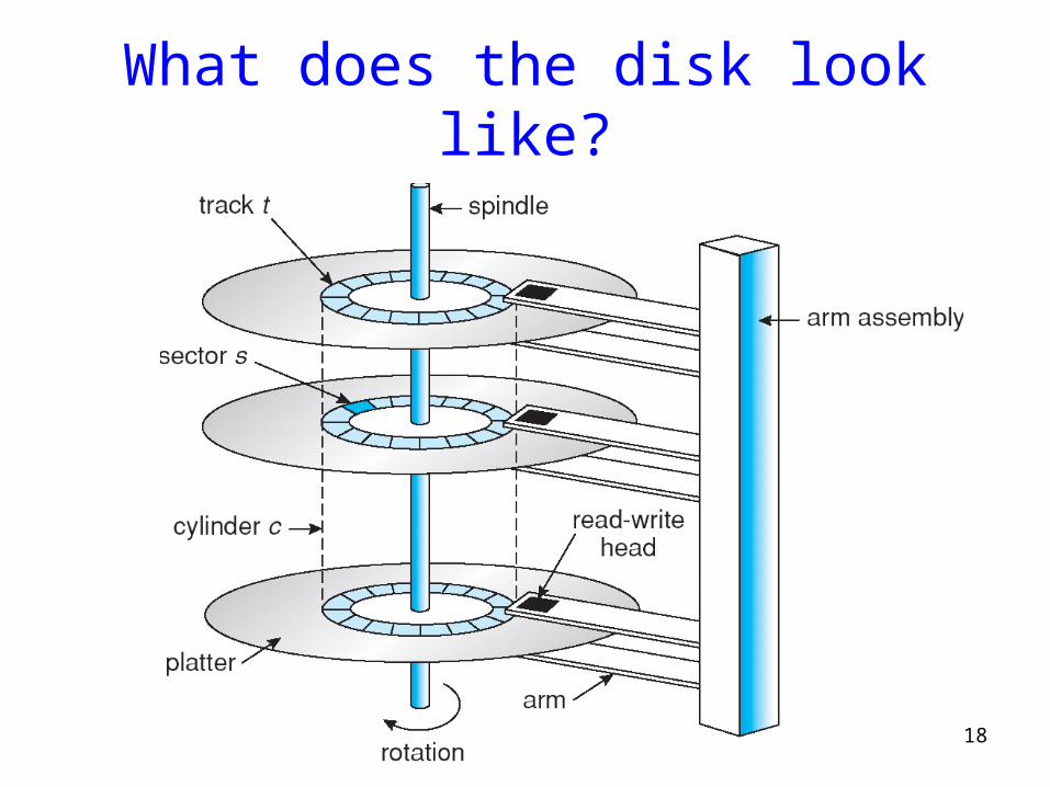
What does the disk look like?

19
Some parameters
• 2-30 heads (platters * 2)– diameter 14’’ to 2.5’’
• 700-20480 tracks per surface• 16-1600 sectors per track• sector size:
– 64-8k bytes
– 512 for most PCs
– note: inter-sector gaps
• capacity: 20M-300G
• main adjectives: BIG, slow

20
Disk overheads• To read from disk, we must specify:
– cylinder #, surface #, sector #, transfer size, memory address
• Transfer time includes: – Seek time: to get to the track – Latency time: to get to the sector and – Transfer time: get bits off the disk
Track
Sector
Seek Time
RotationDelay

21
Modern disks
Barracuda 180 Cheetah X15 36LP
Capacity 181GB 36.7GB
Disk/Heads 12/24 4/8
Cylinders 24,247 18,479
Sectors/track ~609 ~485
Speed 7200RPM 15000RPM
Latency (ms) 4.17 2.0
Avg seek (ms) 7.4/8.2 3.6/4.2
Track-2-track(ms) 0.8/1.1 0.3/0.4

22
• On 13th September 1956, IBM 305 RAMAC computer system first to use disk storage
• 80000 times more data on the 8GB 1-inch drive in his right hand than on the 24-inch RAMAC one in his left…
52 years ago…
23
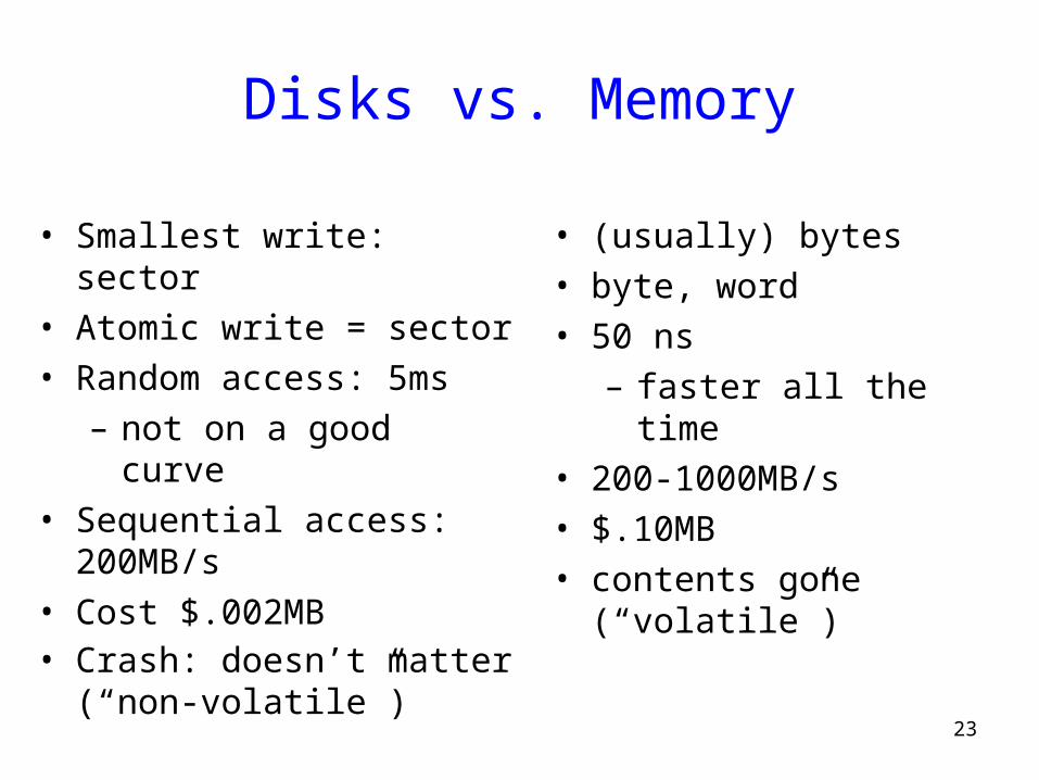
Disks vs. Memory
• Smallest write: sector• Atomic write = sector• Random access: 5ms
– not on a good curve• Sequential access: 200MB/s• Cost $.002MB • Crash: doesn’t matter (“non-
volatile”)
• (usually) bytes• byte, word• 50 ns
– faster all the time• 200-1000MB/s• $.10MB• contents gone (“volatile”)

24
Disk Structure
• Disk drives addressed as 1-dim arrays of logical blocks– the logical block is the smallest unit of transfer
• This array mapped sequentially onto disk sectors– Address 0 is 1st sector of 1st track of the outermost cylinder
– Addresses incremented within track, then within tracks of the cylinder, then across cylinders, from innermost to outermost
• Translation is theoretically possible, but usually difficult– Some sectors might be defective
– Number of sectors per track is not a constant

25
Non-uniform #sectors / track• Maintain same data rate with Constant Linear Velocity• Approaches:
– Reduce bit density per track for outer layers– Have more sectors per track on the outer layers (virtual geometry)

26
Disk Scheduling
• The operating system tries to use hardware efficiently– for disk drives having fast access time, disk bandwidth
• Access time has two major components– Seek time is time to move the heads to the cylinder containing
the desired sector– Rotational latency is additional time waiting to rotate the desired
sector to the disk head.
• Minimize seek time• Seek time seek distance• Disk bandwidth is total number of bytes transferred,
divided by the total time between the first request for service and the completion of the last transfer.

27
Disk Scheduling (Cont.)
• Several scheduling algos exist service disk I/O requests. • We illustrate them with a request queue (0-199).
98, 183, 37, 122, 14, 124, 65, 67
Head pointer 53

28
FCFSIllustration shows total head movement of 640 cylinders.
29
SSTF
• Selects request with minimum seek time from current head position
• SSTF scheduling is a form of SJF scheduling – may cause starvation of some requests.
• Illustration shows total head movement of 236 cylinders.

30
SSTF (Cont.)

31
SCAN
• The disk arm starts at one end of the disk, – moves toward the other end, servicing requests – head movement is reversed when it gets to the other end of disk – servicing continues.
• Sometimes called the elevator algorithm.• Illustration shows total head movement of 236 cylinders.

32
SCAN (Cont.)

33
C-SCAN
• Provides a more uniform wait time than SCAN.• The head moves from one end of the disk to the other.
– servicing requests as it goes. – When it reaches the other end it immediately returns to
beginning of the disk• No requests serviced on the return trip.
• Treats the cylinders as a circular list – that wraps around from the last cylinder to the first one.

34
C-SCAN (Cont.)
35
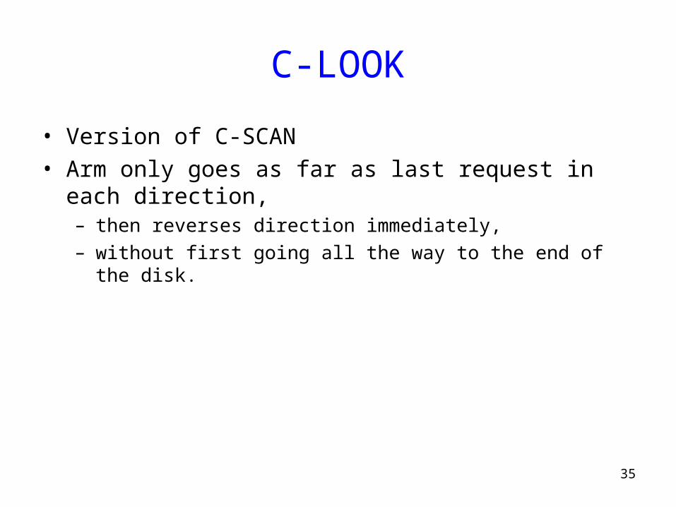
C-LOOK
• Version of C-SCAN• Arm only goes as far as last request in each direction,
– then reverses direction immediately, – without first going all the way to the end of the disk.

36
C-LOOK (Cont.)

37
Selecting a Good Algorithm
• SSTF is common and has a natural appeal
• SCAN and C-SCAN perform better under heavy load
• Performance depends on number and types of requests
• Requests for disk service can be influenced by the file-allocation method.
• Disk-scheduling algo should be a separate OS module – allowing it to be replaced with a different algorithm if necessary.
• Either SSTF or LOOK is a reasonable default algo

38
Summary• I/O Devices Types:
– Many different speeds (0.1 bytes/sec to GBytes/sec)– Different Access Patterns:
• Block Devices, Character Devices, Network Devices– Different Access Timing:
• Blocking, Non-blocking, Asynchronous
• I/O Controllers: Hardware that controls actual device– Processor Accesses through I/O instructions, load/store to special
physical memory– Report their results through either interrupts or a status register that
processor looks at occasionally (polling)• Device Driver: Device-specific code in kernel• Disks:
– Latency Seek + Rotational + Transfer• Also, queuing time
– Rotational latency: on average ½ rotation
• Improve performance (decrease queuing time) via scheduling

39
Announcements• Homework 4 available later tonight
– It is a programming assignment, so start early
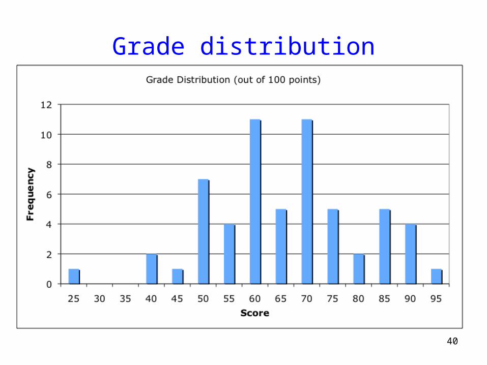
• Prelims graded– Mean 67.7 (Median 67), Stddev 14.2, High 96 out of 100!– Good job!
• Re-grade policy– Submit written re-grade request to Nazrul.
• Entire prelim will be re-graded. • We were generous the first time…
– If still unhappy, submit another re-grade request. • Nazrul will re-grade herself
– If still unhappy, submit a third re-grade request. • I will re-grade. Final grade is law.
40
Grade distribution

Question #2
• Algorithm– (1) Pick up a knife– (2) Pick a fork– (3) Cut out a slice of pizza and eat it– (4) Return the knife and fork to the pile
• Correctness Constraints– wait for a knife and then a fork, in that order! – Key: Deadlock cannot occur since algorithm defines partial order
thus, no circular waiting exists
41

Question #3• 32 bit virtual address and 32-bit physical address, 8kB pages• #bits for offset? #bits for index?• Bytes required for PTE? Bytes required for page table?• 3 bytes and 219*3=1.5 MB, respectively
42
19 bits 13 bitsOffsetVirtual
index
PageTablePtrA frame #frame #
frame #frame #frame #
VDRWE
VDRWE
frame # VDRWE
VDRWE
VDRWE
VDRWE
0
1
2
3
…
219-1
OffsetPhysicalframe #
24 bits = 3 bytes PTE
5 bits 19 bits
13 bits19 bits
32 bits
Physical Address
32 bits
Virtual Address
13 and 19, respectively
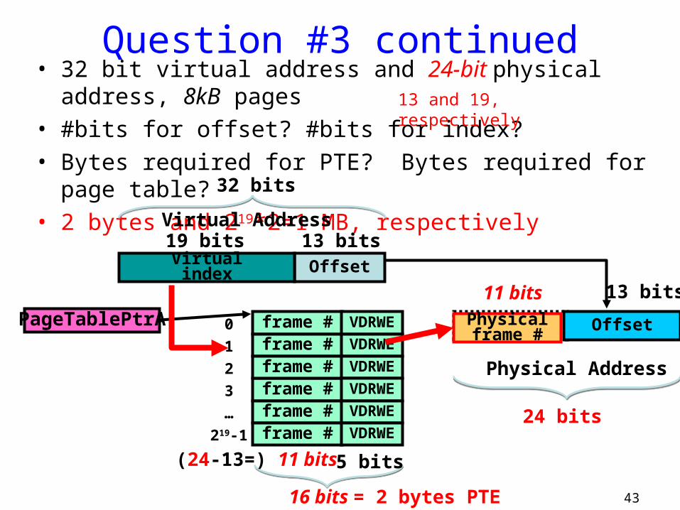
Question #3 continued• 32 bit virtual address and 24-bit physical address, 8kB pages• #bits for offset? #bits for index?• Bytes required for PTE? Bytes required for page table?• 2 bytes and 219*2=1 MB, respectively
43
19 bits 13 bitsOffsetVirtual
index
PageTablePtrA frame #frame #
frame #frame #frame #
VDRWE
VDRWE
frame # VDRWE
VDRWE
VDRWE
VDRWE
0
1
2
3
…
219-1
OffsetPhysicalframe #
16 bits = 2 bytes PTE
5 bits(24-13=) 11 bits
13 bits11 bits
24 bits
Physical Address
32 bits
Virtual Address
13 and 19, respectively

Question #4
• Give a brief definition of the term “working set?”– Virtual memory pages touched within a window of time (or
window of page references).
44

Question #5: CPU Scheduling
• CPU Utilization w/ 10 I/O bound process and 1 CPU-bound– I/O bound compute for 1ms, sleep for 10ms– CPU bound computes indefinitely– Context-switch overhead is 0.1ms
• CPU utilization w/ 1 ms quantum?– scheduler incurs a 0.1ms context-switching cost for every context-switch,
regardless of process type– Cpu util = execTime/(execTime+contextSwitch) = 1/(1+0.1)=0.9090
• CPU utilization w/ 10 ms quantum?– #I/O*exI + #CPU*exC / (#I/O*(exI+cs) + #CPU*(exC+cs))– 10*1 + 1*10 / (10*(1+0.1) + 1*(10+0.1)) – 20/(11+10.1) = 20/21.1 = 0.9478673
45

Question #5 continued
• What strategy can a process employ to maximize the amount of CPU time allocated to that process?
• Multilevel(-feedback) queue– Use a large fraction of assigned quantum– then relinquish the CPU before end of quantum– thus, increasing the priority associated with the process
• Round robin– Use entire quantum
• Or say no specific strategy
– Alternatively, use more threads
46

47
How is the disk formatted?
• After manufacturing disk has no information– Is stack of platters coated with magnetizable metal oxide
• Before use, each platter receives low-level format– Format has series of concentric tracks– Each track contains some sectors– There is a short gap between sectors
• Preamble allows h/w to recognize start of sector– Also contains cylinder and sector numbers– Data is usually 512 bytes– ECC field used to detect and recover from read errors
48
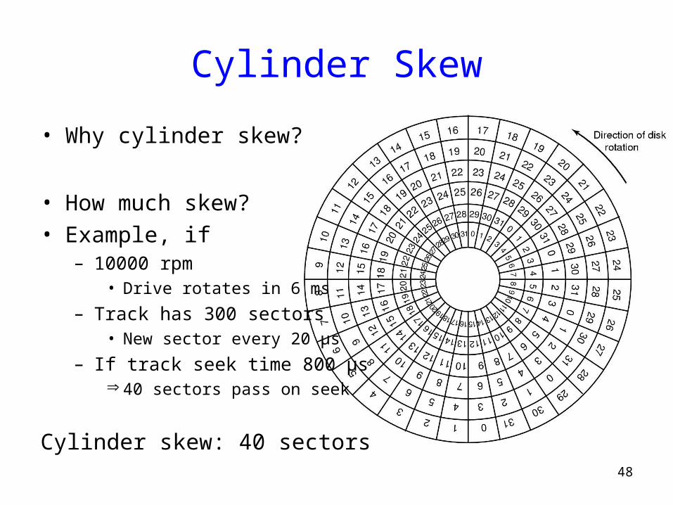
Cylinder Skew
• Why cylinder skew?
• How much skew?• Example, if
– 10000 rpm• Drive rotates in 6 ms
– Track has 300 sectors• New sector every 20 µs
– If track seek time 800 µs 40 sectors pass on seek
Cylinder skew: 40 sectors
49
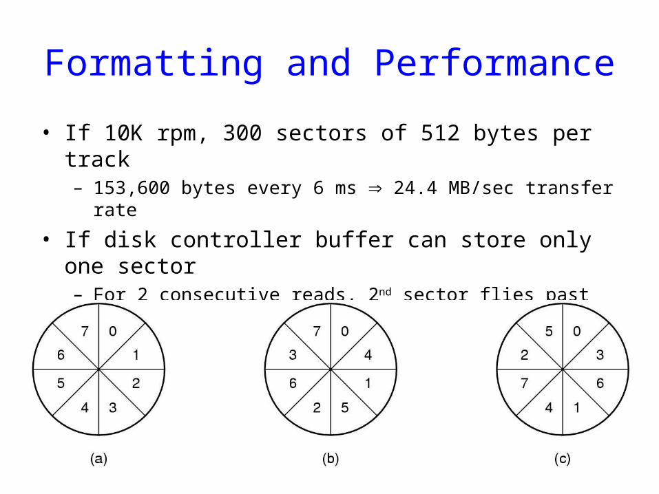
Formatting and Performance
• If 10K rpm, 300 sectors of 512 bytes per track– 153,600 bytes every 6 ms 24.4 MB/sec transfer rate
• If disk controller buffer can store only one sector– For 2 consecutive reads, 2nd sector flies past during memory
transfer of 1st track– Idea: Use single/double interleaving

50
Disk Partitioning
• Each partition is like a separate disk• Sector 0 is MBR
– Contains boot code + partition table
– Partition table has starting sector and size of each partition
• High-level formatting– Done for each partition
– Specifies boot block, free list, root directory, empty file system
• What happens on boot?– BIOS loads MBR, boot program checks to see active partition
– Reads boot sector from that partition that then loads OS kernel, etc.

51
Handling Errors
• A disk track with a bad sector• Solutions:
– Substitute a spare for the bad sector (sector sparing)– Shift all sectors to bypass bad one (sector forwarding)
52
RAID Motivation• Disks are improving, but not as fast as CPUs
– 1970s seek time: 50-100 ms.– 2000s seek time: <5 ms.– Factor of 20 improvement in 3 decades
• We can use multiple disks for improving performance– By Striping files across multiple disks (placing parts of each file on
a different disk), parallel I/O can improve access time
• Striping reduces reliability – 100 disks have 1/100th mean time between failures of one disk
• So, we need Striping for performance, but we need something to help with reliability / availability
• To improve reliability, we can add redundant data to the disks, in addition to Striping

53
RAID• A RAID is a Redundant Array of Inexpensive Disks
– In industry, “I” is for “Independent”– The alternative is SLED, single large expensive disk
• Disks are small and cheap, so it’s easy to put lots of disks (10s to 100s) in one box for increased storage, performance, and availability
• The RAID box with a RAID controller looks just like a SLED to the computer
• Data plus some redundant information is Striped across the disks in some way
• How that Striping is done is key to performance and reliability.
54
Some Raid Issues• Granularity
– fine-grained: Stripe each file over all disks. This gives high throughput for the file, but limits to transfer of 1 file at a time
– coarse-grained: Stripe each file over only a few disks. This limits throughput for 1 file but allows more parallel file access
• Redundancy– uniformly distribute redundancy info on disks: avoids load-
balancing problems
– concentrate redundancy info on a small number of disks: partition the set into data disks and redundant disks

55
Raid Level 0• Level 0 is nonredundant disk array• Files are Striped across disks, no redundant info• High read throughput• Best write throughput (no redundant info to write)• Any disk failure results in data loss
– Reliability worse than SLED
Stripe 0
Stripe 4
Stripe 3Stripe 1 Stripe 2
Stripe 8 Stripe 10 Stripe 11
Stripe 7Stripe 6Stripe 5
Stripe 9
data disks

56
Raid Level 1• Mirrored Disks• Data is written to two places
– On failure, just use surviving disk
• On read, choose fastest to read – Write performance is same as single drive, read
performance is 2x better
• Expensive
data disks mirror copies
Stripe 0
Stripe 4
Stripe 3Stripe 1 Stripe 2
Stripe 8 Stripe 10 Stripe 11
Stripe 7Stripe 6Stripe 5
Stripe 9
Stripe 0
Stripe 4
Stripe 3Stripe 1 Stripe 2
Stripe 8 Stripe 10 Stripe 11
Stripe 7Stripe 6Stripe 5
Stripe 9

57
Parity and Hamming Code
• What do you need to do in order to detect and correct a one-bit error ?– Suppose you have a binary number, represented as a
collection of bits: <b3, b2, b1, b0>, e.g. 0110
• Detection is easy• Parity:
– Count the number of bits that are on, see if it’s odd or even• EVEN parity is 0 if the number of 1 bits is even
– Parity(<b3, b2, b1, b0 >) = P0 = b0 b1 b2 b3– Parity(<b3, b2, b1, b0, p0>) = 0 if all bits are intact– Parity(0110) = 0, Parity(01100) = 0– Parity(11100) = 1 => ERROR!– Parity can detect a single error, but can’t tell you which of
the bits got flipped

58
Parity and Hamming Code• Detection and correction require more work• Hamming codes can detect double bit errors and detect &
correct single bit errors• 7/4 Hamming Code
– h0 = b0 b1 b3– h1 = b0 b2 b3– h2 = b1 b2 b3– H0(<1101>) = 0– H1(<1101>) = 1– H2(<1101>) = 0– Hamming(<1101>) = <b3, b2, b1, h2, b0, h1, h0> =
<1100110>– If a bit is flipped, e.g. <1110110>– Hamming(<1111>) = <h2, h1, h0> = <111> compared to
<010>, <101> are in error. Error occurred in bit 5.

59
Raid Level 2• Bit-level Striping with Hamming (ECC) codes for error correction• All 7 disk arms are synchronized and move in unison• Complicated controller• Single access at a time• Tolerates only one error, but with no performance degradation
data disks
Bit 0 Bit 3Bit 1 Bit 2 Bit 4 Bit 5 Bit 6
ECC disks
60
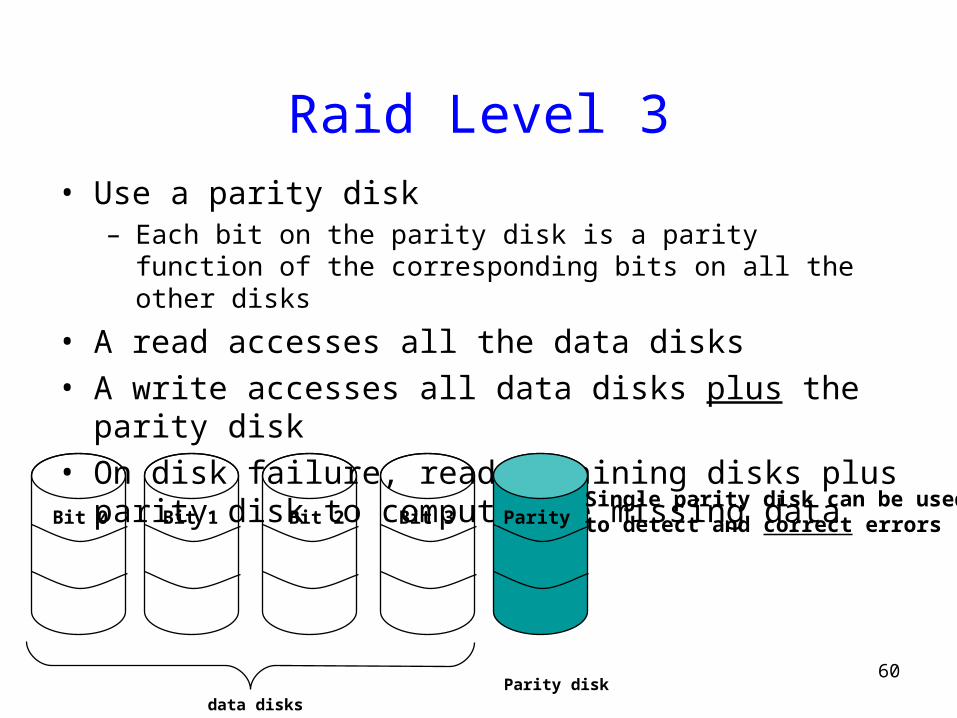
Raid Level 3• Use a parity disk
– Each bit on the parity disk is a parity function of the corresponding bits on all the other disks
• A read accesses all the data disks• A write accesses all data disks plus the parity disk• On disk failure, read remaining disks plus parity disk to
compute the missing data
data disksParity disk
Bit 0 Bit 3Bit 1 Bit 2 ParitySingle parity disk can be usedto detect and correct errors

61
Raid Level 4
• Combines Level 0 and 3 – block-level parity with Stripes• A read accesses all the data disks• A write accesses all data disks plus the parity disk• Heavy load on the parity disk
data disksParity disk
Stripe 0 Stripe 3Stripe 1 Stripe 2 P0-3
Stripe 4
Stripe 8
Stripe 10 Stripe 11
Stripe 7Stripe 6Stripe 5
Stripe 9
P4-7
P8-11

62
Raid Level 5
• Block Interleaved Distributed Parity• Like parity scheme, but distribute the parity info over
all disks (as well as data over all disks)• Better read performance, large write performance
– Reads can outperform SLEDs and RAID-0
data and parity disks
Stripe 0 Stripe 3Stripe 1 Stripe 2 P0-3
Stripe 4
Stripe 8 P8-11 Stripe 10
P4-7Stripe 6Stripe 5
Stripe 9
Stripe 7
Stripe 11

63
Raid Level 6
• Level 5 with an extra parity bit• Can tolerate two failures
– What are the odds of having two concurrent failures ?
• May outperform Level-5 on reads, slower on writes

64
RAID 0+1 and 1+0
65
Stable Storage
• Handling disk write errors:– Write lays down bad data
– Crash during a write corrupts original data
• What we want to achieve? Stable Storage– When a write is issued, the disk either correctly writes data, or it does
nothing, leaving existing data intact
• Model:– An incorrect disk write can be detected by looking at the ECC
– It is very rare that same sector goes bad on multiple disks
– CPU is fail-stop

66
Approach• Use 2 identical disks
– corresponding blocks on both drives are the same
• 3 operations:– Stable write: retry on 1st until successful, then try 2nd disk– Stable read: read from 1st. If ECC error, then try 2nd – Crash recovery: scan corresponding blocks on both disks
• If one block is bad, replace with good one
• If both are good, replace block in 2nd with the one in 1st

67
CD-ROMs
Spiral makes 22,188 revolutions around disk (approx 600/mm).
Will be 5.6 km long. Rotation rate: 530 rpm to 200 rpm

68
CD-ROMs
Logical data layout on a CD-ROM