investigation of the force and moment effects of st …
TRANSCRIPT
Middle East Journal of Science (2018) 4(1): 23-35
23
INTERNATIONAL
ENGINEERING,
SCIENCE AND
EDUCATION
GROUP
Middle East Journal of Science (2018) 4(1): 23 -35
Published online JUNE 2018 (http://dergipark.gov.tr/mejs)
doi: 10.23884/mejs.2018.4.1.04
e-ISSN 2618-6136
Received: May 15, 2018 Accepted:June 3, 2018
INVESTIGATION OF THE FORCE AND MOMENT EFFECTS OF ST 37 AND ST 70 ROOF
LATTICE STEELS IN ANSYS PROGRAM
Semih TAŞKAYA1, Bilgin ZENGİN* 2, Kürşat KAYMAZ 3
1Department of Metallurgy and Materials Engineering, University of Firat, Elazig / TURKEY
*2Department of Electrical and Electronics Engineering, University of Munzur, Tunceli / TURKEY 3Department of Civil Engineering, University of Munzur, Tunceli / TURKEY
*Corresponding author; [email protected]
Abstract: St 37 and St 70 steels are the materials used in the manufacturing
of general building materials, which are produced by processing the hot-
formed steel further through a cold drawing process. Finite element method
helps to simplify the complex engineering problems and to solve them with
controllable parts. The roof lattice model simulated in the present study is a
4-surface pyramidal roof which is 4 mm in diameter, 0.5 mm in thickness
and it was designed in 3D in Ansys software by using the finite element
method. The bottom corner nodes of the roof lattice model were stabilized
and the vector stress effects of 65.000 N force was applied in Fx, Fz
directions and 75.000 N force was applied in Fy direction on the top node
truss axes, 65.000 N.m moment was applied in Mx, Mz directions and 75.000
N.m moment was applied in My direction on middle truss nodes were
investigated. According to the test results in Ansys software, vector stress
increase due to both force and moment effect in truss axes of the St 70 lattice
roof steel compared to the St 37 steel.
Key words: St 37- St 70, Ansys, Force and moment, Finite element method.
Middle East Journal of Science (2018) 4(1): 23-35
24
1. Introduction
St 37 steel is a non-alloy steel. Its mechanical properties are over 235 MPa of yield strength and
360-510 MPa of tensile strength. It is primarily used for riveting, screwing and welding purposes. St
37 structural steel material is utilized in many applications, combining its good welding properties
with guaranteed strengths. There are various grades and uses including civil and industrial
engineering. High strength low alloys have replaced many structural steels where weight reduction is
important (e.g. automotive) but with guaranteed strengths [1]. Mechanical properties of St 70 steel are
over 365 MPa yield strength and 690-900 MPa of tensile strength, and it is primarily used for riveting,
screwing and welding purposes [2]. The finite element method is a promising tool in the modeling of
several mechanical applications related to aerospace and civil engineering. One of the its most
exciting prospects is that it finds application on the coupled problems such as fluid-structure
interaction, thermomechanical, thermochemical, thermo-chemo-mechanical problems, biomechanics,
biomedical engineering, piezoelectric, ferroelectric, and electromagnetics [3]. In a study by
Rottensteiner et al. (2014), the detection of roof planes from the analysis of three-dimensional (3D)
point clouds and Digital Surface Models (DSMs) is an active research and application subject. Jochem
et al. (2009) developed a representation of building spaces in 3-dimensional city models when roof
planes were included in the models appropriately [5]. Huang et al (2013) used a generative modeling
based on a primitive library for roof detection and reconstruction. The study also included combining
the bottom-up and top-down approaches [6]. As suggested by Vitti (2012), areas with uniform gradient
(i.e. planar) patches and boundaries (i.e. roof edges and eaves) can be detected by using the global
variability model, which is a second-order model suggested by Blake and Zisserman (1987) [7-8].
Ohtake et al. (2004) performed an edge detection on triangular meshes by analyzing the principal
curvatures and their derivatives [9]. Rottensteiner (2003) applied a region growing model on normal
vectors in the production of the 3-dimensional building models [10]. Wang et al. (2013) considered the
normal vectors as points on unit sphere, and then segmented planes and other orderly surfaces for
detection [11].
2. Materials And Method
According to the finite element method in Ansys 12.0 software package, roof lattice modeling
structure of St 37 and St 70 steels 3D design of a 4-surface pyramidal roof with the dimensions of 4
mm in diameter and 0.5 mm in wall thickness was designed according to the mechanical properties
presented in Table 1 and Table 2.
Table 1. Mechanical properties of St 37 steel [12]
Material Density
(kg/m3)
Elasticity
Module
(MPa)
Elongation
(%)
Poisson
Ratio
Tensile
Strength
(MPa)
Yield
Strength
(MPa)
St 37 8000 210000 15 0.3 360-470 225-235
Middle East Journal of Science (2018) 4(1): 23-35
25
Table 2. Mechanical properties of St 70 [13]
Material Density
(kg/m3)
Elasticity
Module
(MPa)
Elongation
(%)
Poisson
Ratio
Tensile
Strength
(MPa)
Yield
Strength
(MPa)
St 70 7700 200000 8-25 0.3 650-880 350-550
2.1. Modeling
For the roof lattice model design by using the St 37 and St 70 steel standards, only one roof
lattice profile was used for each element type. Following the various analyses on the same model,
mechanical properties were identified and analysis was performed. In the first stage of the modeling,
the analysis type is selected as “structural analysis”. During the analysis of the model, the most
significant parameter of element type is determined. Since the most commonly used process in roof
lattice model is pipes, the element type is selected as “Pipe / elastic straight 16”. The purpose of
selecting this element type is to enable easy transfer of mechanical properties and achieve a solution.
The mechanical data for the model are defined into the material characteristics module according to
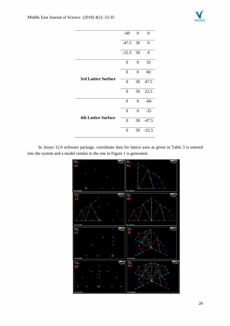
the Table 1 and Table 2. In the next stage, according to the coordinates given in Table 3, key points of
4 different roof surfaces are identified for each axis as shown in Figure 1 and a pyramidal roof model
is generated.
Table 3. Key point measurements of the roof lattice model for each axis
Measurements of Roof
Lattice Surfaces X Y Z
1st Lattice Surface
0 0 0
35 0 0
60 0 0
47.5 30 0
22.5 50 0
0 40 0
0 70 0
2nd Lattice Surface -35 0 0
Middle East Journal of Science (2018) 4(1): 23-35
26
-60 0 0
-47.5 30 0
-22.5 50 0
3rd Lattice Surface
0 0 35
0 0 60
0 30 47.5
0 50 22.5
4th Lattice Surface
0 0 -60
0 0 -35
0 30 -47.5
0 50 -22.5
In Ansys 12.0 software package, coordinate data for lattice axes as given in Table 3 is entered
into the system and a model similar to the one in Figure 1 is generated.
Middle East Journal of Science (2018) 4(1): 23-35
27
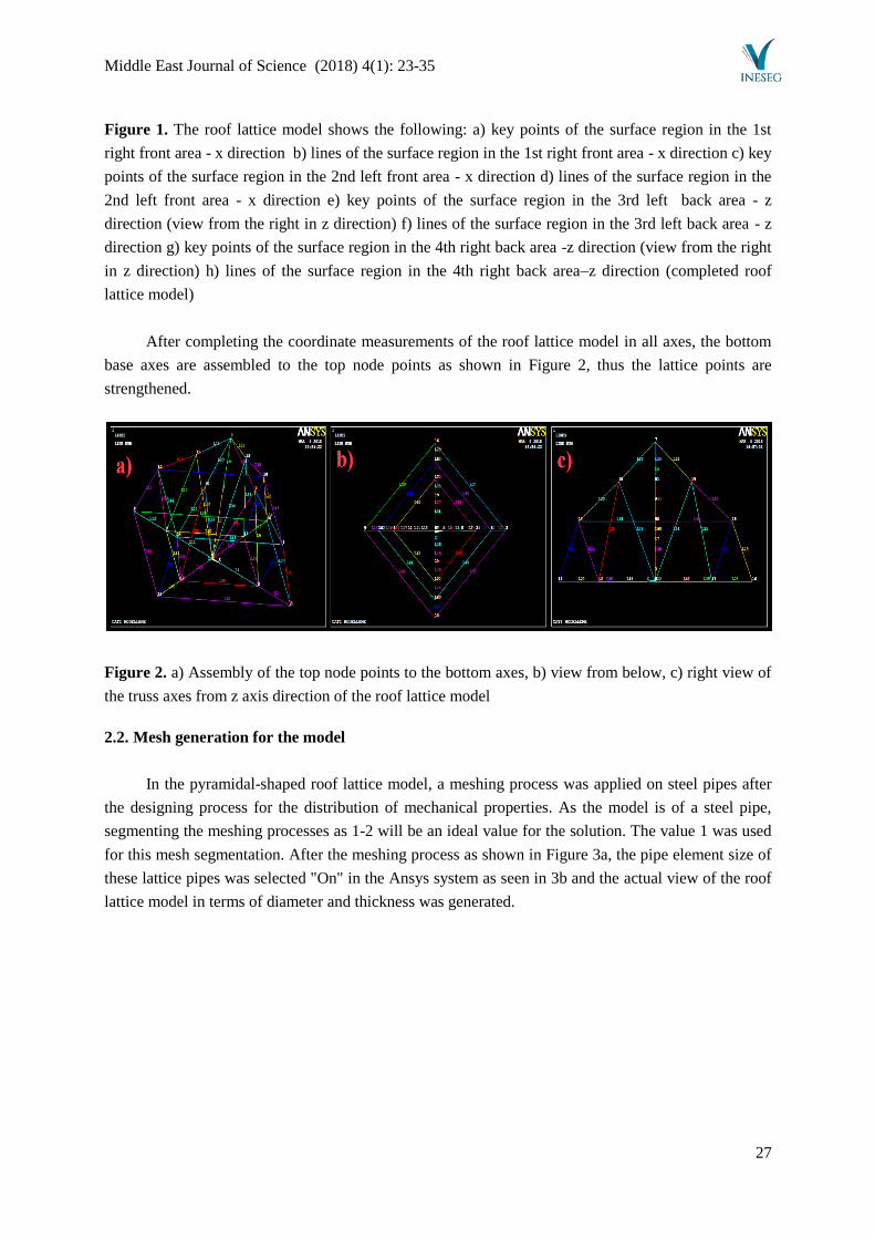
Figure 1. The roof lattice model shows the following: a) key points of the surface region in the 1st
right front area - x direction b) lines of the surface region in the 1st right front area - x direction c) key
points of the surface region in the 2nd left front area - x direction d) lines of the surface region in the
2nd left front area - x direction e) key points of the surface region in the 3rd left back area - z
direction (view from the right in z direction) f) lines of the surface region in the 3rd left back area - z
direction g) key points of the surface region in the 4th right back area -z direction (view from the right
in z direction) h) lines of the surface region in the 4th right back area–z direction (completed roof
lattice model)
After completing the coordinate measurements of the roof lattice model in all axes, the bottom
base axes are assembled to the top node points as shown in Figure 2, thus the lattice points are
strengthened.
Figure 2. a) Assembly of the top node points to the bottom axes, b) view from below, c) right view of
the truss axes from z axis direction of the roof lattice model
2.2. Mesh generation for the model
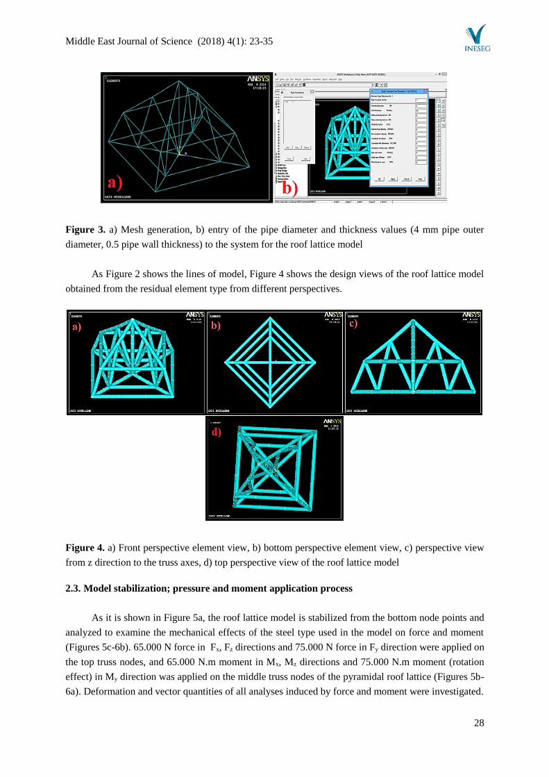
In the pyramidal-shaped roof lattice model, a meshing process was applied on steel pipes after
the designing process for the distribution of mechanical properties. As the model is of a steel pipe,
segmenting the meshing processes as 1-2 will be an ideal value for the solution. The value 1 was used
for this mesh segmentation. After the meshing process as shown in Figure 3a, the pipe element size of
these lattice pipes was selected "On" in the Ansys system as seen in 3b and the actual view of the roof
lattice model in terms of diameter and thickness was generated.
Middle East Journal of Science (2018) 4(1): 23-35
28
Figure 3. a) Mesh generation, b) entry of the pipe diameter and thickness values (4 mm pipe outer
diameter, 0.5 pipe wall thickness) to the system for the roof lattice model
As Figure 2 shows the lines of model, Figure 4 shows the design views of the roof lattice model
obtained from the residual element type from different perspectives.
Figure 4. a) Front perspective element view, b) bottom perspective element view, c) perspective view
from z direction to the truss axes, d) top perspective view of the roof lattice model
2.3. Model stabilization; pressure and moment application process
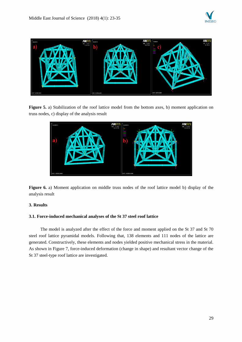
As it is shown in Figure 5a, the roof lattice model is stabilized from the bottom node points and
analyzed to examine the mechanical effects of the steel type used in the model on force and moment
(Figures 5c-6b). 65.000 N force in Fx, Fz directions and 75.000 N force in Fy direction were applied on
the top truss nodes, and 65.000 N.m moment in Mx, Mz directions and 75.000 N.m moment (rotation
effect) in My direction was applied on the middle truss nodes of the pyramidal roof lattice (Figures 5b-
6a). Deformation and vector quantities of all analyses induced by force and moment were investigated.
Middle East Journal of Science (2018) 4(1): 23-35
29
Figure 5. a) Stabilization of the roof lattice model from the bottom axes, b) moment application on
truss nodes, c) display of the analysis result
Figure 6. a) Moment application on middle truss nodes of the roof lattice model b) display of the
analysis result
3. Results
3.1. Force-induced mechanical analyses of the St 37 steel roof lattice
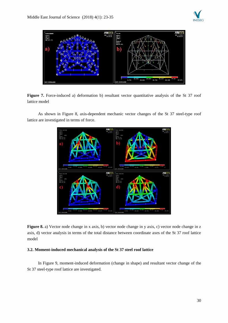
The model is analyzed after the effect of the force and moment applied on the St 37 and St 70
steel roof lattice pyramidal models. Following that, 138 elements and 111 nodes of the lattice are
generated. Constructively, these elements and nodes yielded positive mechanical stress in the material.
As shown in Figure 7, force-induced deformation (change in shape) and resultant vector change of the
St 37 steel-type roof lattice are investigated.
Middle East Journal of Science (2018) 4(1): 23-35
30
Figure 7. Force-induced a) deformation b) resultant vector quantitative analysis of the St 37 roof
lattice model
As shown in Figure 8, axis-dependent mechanic vector changes of the St 37 steel-type roof
lattice are investigated in terms of force.
Figure 8. a) Vector node change in x axis, b) vector node change in y axis, c) vector node change in z
axis, d) vector analysis in terms of the total distance between coordinate axes of the St 37 roof lattice
model
3.2. Moment-induced mechanical analysis of the St 37 steel roof lattice
In Figure 9, moment-induced deformation (change in shape) and resultant vector change of the
St 37 steel-type roof lattice are investigated.
Middle East Journal of Science (2018) 4(1): 23-35
31
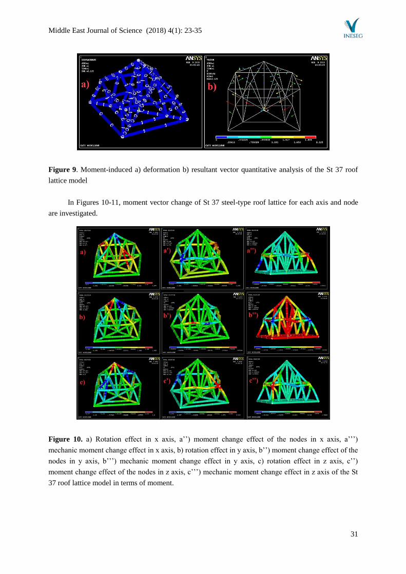
Figure 9. Moment-induced a) deformation b) resultant vector quantitative analysis of the St 37 roof
lattice model
In Figures 10-11, moment vector change of St 37 steel-type roof lattice for each axis and node
are investigated.
Figure 10. a) Rotation effect in x axis, a’’) moment change effect of the nodes in x axis, a’’’)
mechanic moment change effect in x axis, b) rotation effect in y axis, b’’) moment change effect of the
nodes in y axis, b’’’) mechanic moment change effect in y axis, c) rotation effect in z axis, c’’)
moment change effect of the nodes in z axis, c’’’) mechanic moment change effect in z axis of the St
37 roof lattice model in terms of moment.
Middle East Journal of Science (2018) 4(1): 23-35
32
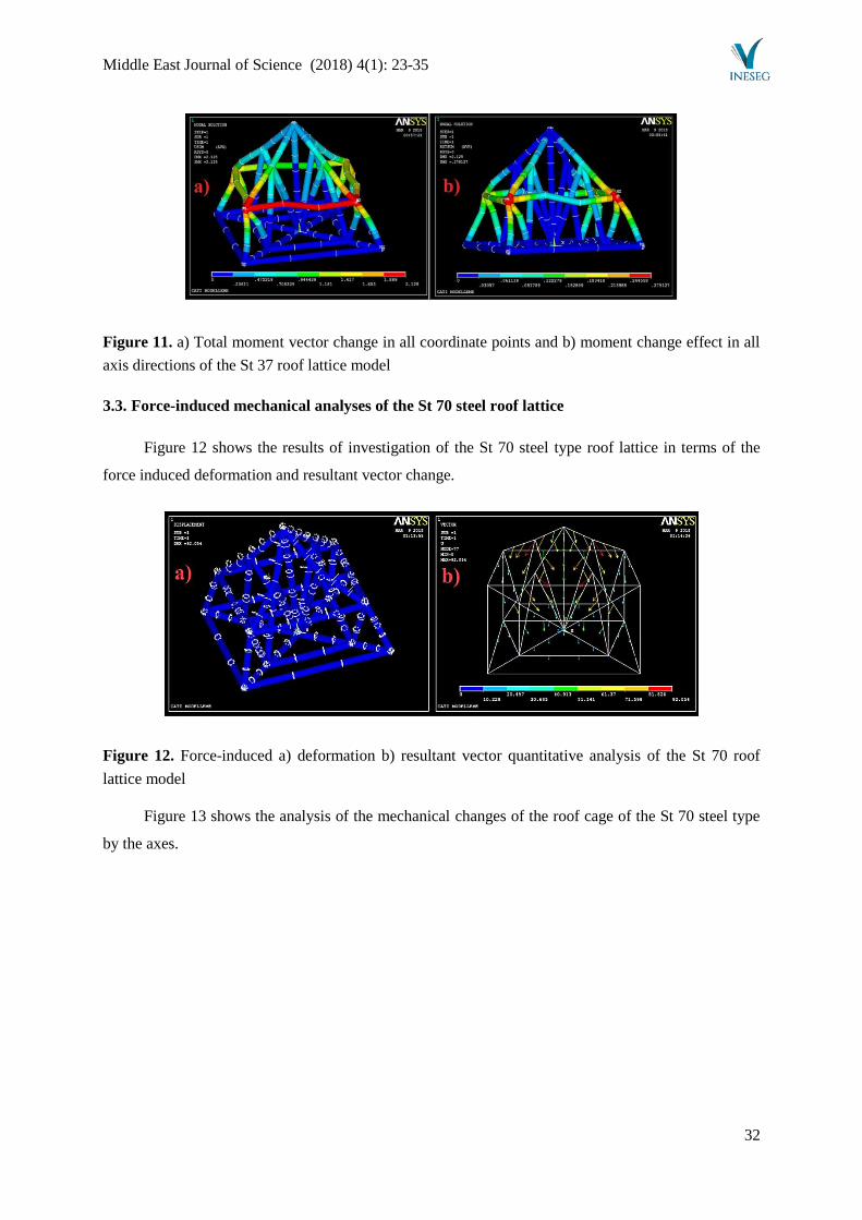
Figure 11. a) Total moment vector change in all coordinate points and b) moment change effect in all
axis directions of the St 37 roof lattice model
3.3. Force-induced mechanical analyses of the St 70 steel roof lattice
Figure 12 shows the results of investigation of the St 70 steel type roof lattice in terms of the
force induced deformation and resultant vector change.
Figure 12. Force-induced a) deformation b) resultant vector quantitative analysis of the St 70 roof
lattice model
Figure 13 shows the analysis of the mechanical changes of the roof cage of the St 70 steel type
by the axes.
Middle East Journal of Science (2018) 4(1): 23-35
33
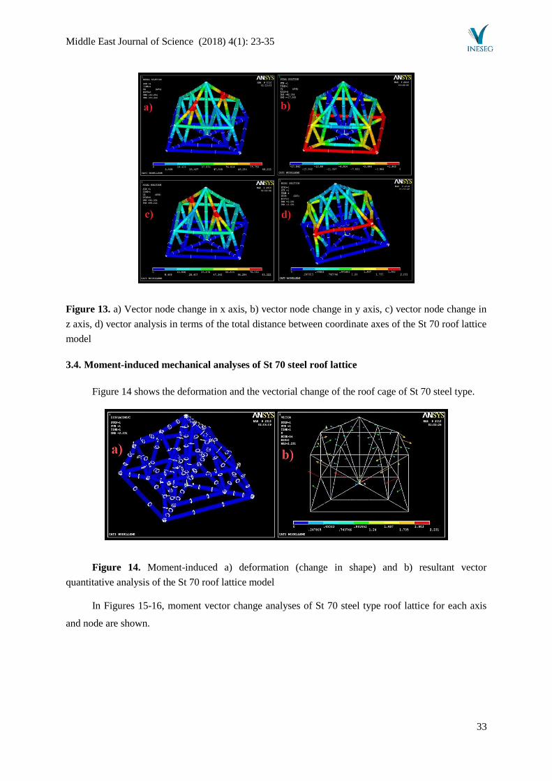
Figure 13. a) Vector node change in x axis, b) vector node change in y axis, c) vector node change in
z axis, d) vector analysis in terms of the total distance between coordinate axes of the St 70 roof lattice
model
3.4. Moment-induced mechanical analyses of St 70 steel roof lattice
Figure 14 shows the deformation and the vectorial change of the roof cage of St 70 steel type.
Figure 14. Moment-induced a) deformation (change in shape) and b) resultant vector
quantitative analysis of the St 70 roof lattice model
In Figures 15-16, moment vector change analyses of St 70 steel type roof lattice for each axis
and node are shown.
Middle East Journal of Science (2018) 4(1): 23-35
34
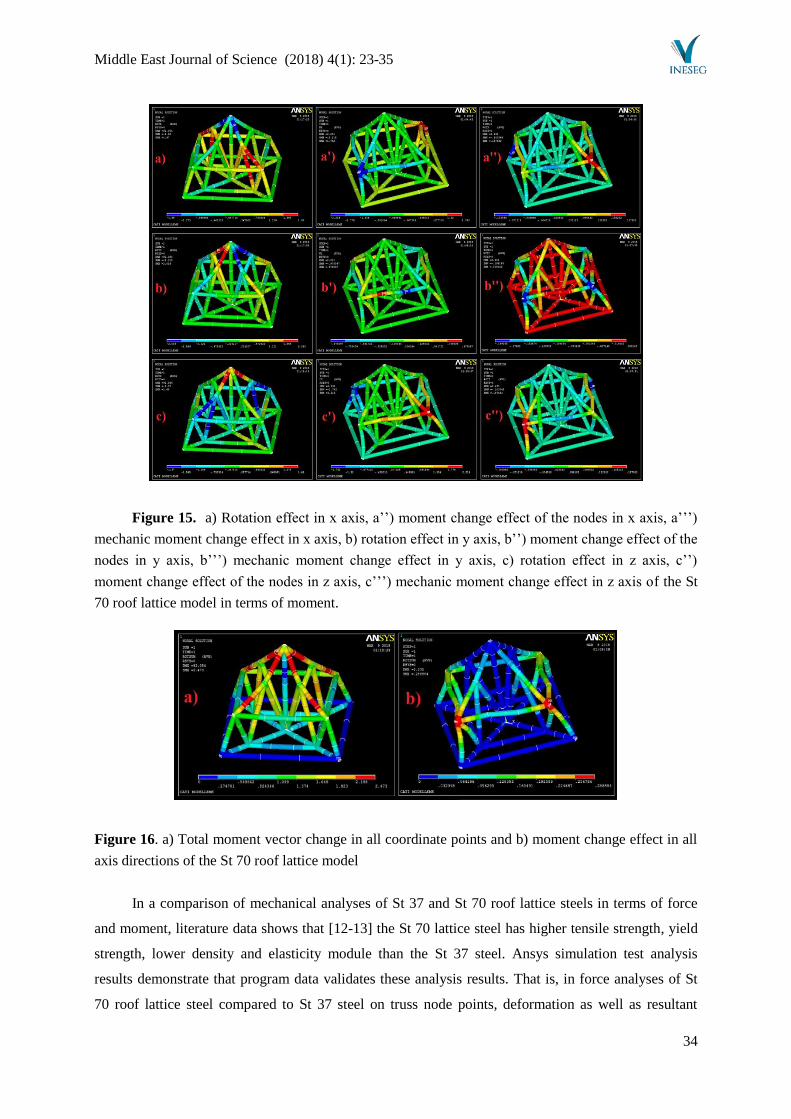
Figure 15. a) Rotation effect in x axis, a’’) moment change effect of the nodes in x axis, a’’’)
mechanic moment change effect in x axis, b) rotation effect in y axis, b’’) moment change effect of the
nodes in y axis, b’’’) mechanic moment change effect in y axis, c) rotation effect in z axis, c’’)
moment change effect of the nodes in z axis, c’’’) mechanic moment change effect in z axis of the St
70 roof lattice model in terms of moment.
Figure 16. a) Total moment vector change in all coordinate points and b) moment change effect in all
axis directions of the St 70 roof lattice model
In a comparison of mechanical analyses of St 37 and St 70 roof lattice steels in terms of force
and moment, literature data shows that [12-13] the St 70 lattice steel has higher tensile strength, yield
strength, lower density and elasticity module than the St 37 steel. Ansys simulation test analysis
results demonstrate that program data validates these analysis results. That is, in force analyses of St
70 roof lattice steel compared to St 37 steel on truss node points, deformation as well as resultant
Middle East Journal of Science (2018) 4(1): 23-35
35
vector stresses and changes in coordinate points of all axes increase. More vector node changings
occur in steels with higher yield strength and tensile strength and lower elasticity module, because the
trusses suffer from more constructive damage. Thus, mechanical stress is higher compared to the St 37
steel. On the other hand, the tensile strength of St 37 steel is low due to its higher elasticity module,
therefore stretching is easier in trusses and less load is imposed on the truss nodes.
A comparison of moment changes caused by the rotation effect on roof lattice steels shows that
it increased in St 70 steel in direct proportion to the result of force-induced mechanic vector simulation
analyses. Similarly, due to the rotation effects in coordinate axes, the highest load accumulation in
terms of tension and pressure movements was found in the St 70 roof lattice steel. Moment vector
changes, rotation effects between axis nodes, resultant vector changes and deformation as well as the
highest mechanical effect were observed in St 70 steel lattice trusses as compared to St 37 roof lattice
steel.
References
[1] ***, Bebon International co., ltd., http://www.steel-plate-sheet.com/Steel-plate/DIN/St372.html
[2] ***, Join-Win Steel, http://www.steel-jw.com/DINEN/ST702-structure-steel-with-competitive-
price.html
[3] ***, Simscale Blog-Finite Element Method, https://www.simscale.com/blog/2016/10/what-is-
finite-element-method/
[4] Rottensteiner, F., Sohn, G., Gerke, M., Wegner, J.D., Breitkopf, U., Jung, J., “Results of the
ISPRS benchmark on urban object detection and 3d building reconstruction”, ISPRS J.
Photogram. Remote Sens., 93, pp. 256-271, 2014.
[5] Jochem, A., Höfle, B., Rutzinger, M., Pfeifer, N., “Automatic roof plane detection and analysis
in airborne LiDAR point clouds for solar potential assessment”, Sensors, 9, pp. 5241-5262,
2009.
[6] Huang, H., Brenner, C., Sester, M., “A generative statistical approach to automatic 3D building
roof reconstruction from laser scanning data”, ISPRS J. Photogram. Remote Sens., 79, pp. 29-
43, 2013.
[7] Vitti, A., “The Mumford-Shah variational model for image segmentation: an overview of the
theory, implementation and use”, ISPRS J. Photogram. Remote Sens., 69, pp. 50-64, 2012.
[8] Blake, A., Zisserman, A., Visual Reconstruction, MIT Press Cambridge, MA, USA, 1987.
[9] Ohtake, Y., Belyaev, A., Seidel, H.P., “Ridge-valley lines on meshes via implicit surface
fitting”, ACM Trans. Graph., 23, pp. 609-612, 2004.
[10] Rottensteiner, F., “Automatic generation of high-quality building models from LiDAR data”,
IEEE Comput. Graphics Appl., 23, pp. 42-50, 2003.
[11] Wang, Y., Hao, W., Ning, X., Zhao, M., Zhang J., Shi, Z., Zhang, X., “Automatic segmentation
of urban point clouds based on the gaussian map”, Photogram. Rec., 28, pp. 342-361, 2013.
[12] Taşkaya S., “Investıgatıon of mechanical stresses dependent on press in St 37 steel Ansys
program”, The Journal of International Manufacturing and Production Technologies
(JIMPOT), 1, pp. 39-46, 2017.
[13] ***, China steel suppliers, http://www.steelgr.com/Steel-Grades/Carbon-Steel/st70-2.html