investigation of stress distribution in a …etd.lib.metu.edu.tr/upload/12612993/index.pdf ·...
TRANSCRIPT
INVESTIGATION OF STRESS DISTRIBUTION IN A DRAGLINE BUCKET
USING FINITE ELEMENT ANALYSIS
A THESIS SUBMITTED TO
THE GRADUATE SCHOOL OF APPLIED AND NATURAL SCIENCES
OF
MIDDLE EAST TECHNICAL UNIVERSITY
BY
ONUR GÖLBAġI
IN PARTIAL FULFILLMENT OF THE REQUIREMENTS
FOR
THE DEGREE OF MASTER OF SCIENCE
IN
MINING ENGINEERING
FEBRUARY 2011
ii
Approval of the thesis:
INVESTIGATION OF STRESS DISTRIBUTION IN A DRAGLINE
BUCKET USING FINITE ELEMENT ANALYSIS
submitted by ONUR GÖLBAŞI in partial fulfillment of the requirements for the
degree of Master of Science in Mining Engineering Department, Middle East
Technical University by,
Prof. Dr. Canan Özgen _____________________
Dean, Graduate School of Natural and Applied Sciences
Prof. Dr. Ali Ġhsan Arol _____________________
Head of Department, Mining Engineering
Asst. Prof. Dr. Nuray Demirel
Supervisor, Mining Engineering Dept., METU _____________________
Examining Committee Members:
Prof. Dr. Naci BölükbaĢı _____________________
Mining Engineering Dept., METU
Asst. Prof. Dr. Nuray Demirel _____________________
Mining Engineering Dept., METU
Prof. Dr. H. ġebnem Düzgün _____________________
Mining Engineering Dept., METU
Assoc. Prof. Dr. Serkan Dağ _____________________
Mechanical Engineering Dept., METU
Ömer Ünver _____________________
World Energy Council, Turkish National Committee
Date: 11.02.2011

iii
I hereby declare that all information in this document has been obtained and
presented in accordance with academic rules and ethical conduct. I also
declare that, as required by these rules and conduct, I have fully cited and
referenced all material and results that are not original to this work.
Name, Last Name: Onur GölbaĢı
Signature :
iv
ABSTRACT
INVESTIGATION OF STRESS DISTRIBUTION IN A DRAGLINE BUCKET
USING FINITE ELEMENT ANALYSIS
GölbaĢı, Onur
M.Sc., Department of Mining Engineering
Supervisor: Asst. Prof. Dr. Nuray Demirel
February 2011, 110 pages
Overburden stripping is one of the essential activities in open-cast mines before
starting the ore production. Due to the economic advantages, dragline is a widely
utilized machinery in the overburden excavation. These earthmovers carry out the
earthmoving process with dragging, hoisting and dumping actions of the bucket.
Dragline excavator’s efficiency is critically important, since poor performance of a
dragline in the mine site directly affects the total efficiency of ore production.
Therefore, productivity studies about dragline should be directed to decrease cycle
time and increase payload, with avoiding catastrophic failure. In this regard,
determination of stress distribution on the front-end components of dragline is
meaningful to detect the external factors against dragline operation.
In order to provide insight into the dragline bucket-formation interaction and stress
distribution on the bucket, this research studies the simulation of horizontally
moving dragline bucket where passive earth forces of the formation create
resistance to the movement. Within the scope of simulation, (i) solid models of
dragline bucket and the rigging mechanism were created in the Computer-Aided
v
Drawing (CAD) environment, (ii) the model was transferred to the Finite-Element
Analysis (FEA) software, (iii) two different case studies were simulated in the FEA
virtual environment. One of the cases handled the stress investigation on the
dragline bucket at the first interaction with the formation, while the other focused
on the stress formations on a moving dragline bucket. Simulation results showed
that overloading conditions occurred on bottom edges of the bucket lip for the first
case, and drag hitch part and digging teeth for the second case. Moreover, a
sensitivity analysis was carried out to measure the effects of formation specification
changes on the stress values on the bucket. The analysis showed that stress values
on the bucket elements were most sensitive to internal friction angle and least
sensitive to density.
Consequently, this thesis study discusses stress and deformation components on the
dragline bucket during the interaction with formation. Since there is not enough
number of research studies in the literature about the stress investigation on a
moving dragline bucket, this thesis study is expected to provide benefit to
understand the basis of dragline bucket actions.
Keywords: Dragline Bucket, Bucket-Formation Interaction, Stress Distribution,
Computer-Aided Design, Finite Element Analysis
vi
ÖZ
SONLU ELEMANLAR ANALĠZĠ ĠLE ÇEKME KEPÇELĠ YERKAZARIN
KEPÇESĠNDEKĠ GERĠLME DAĞILIMININ ĠNCELENMESĠ
GölbaĢı, Onur
Yüksek Lisans, Maden Mühendisliği Bölümü
Tez Yöneticisi: Yrd. Doç. Dr. Nuray Demirel
ġubat 2011, 110 sayfa
Örtü kazı faaliyeti, açık kömür ocaklarında üretime geçilmeden önceki en temel
madencilik aktivitelerinden biridir. Ekonomik faydaları düĢünüldüğü zaman, çekme
kepçeli yerkazarlar, örtü kazı iĢlemlerinde sıklıkla kullanılmaktadır. Bu yerkazarlar
pasa harfiyatını, kepçesinin çekme, kaldırma ve boĢaltma hareketini kullanarak
gerçekleĢtirmektedir. Çekme kepçenin düĢük performansı doğrudan bütün üretim
verimliliğini etkileyeceği için, bu yerkazarların kazı esnasındaki verimliliği önem
arz etmektedir. Bu nedenden ötürü, çekme kepçeli yerkazar için yapılan verimlilik
çalıĢmaları, yapısal bir zarara neden olmayacak Ģekilde, devir sayısını azaltmaya ve
taĢıma yükünü arttırmaya yönelik olmalıdır. Bu bakımdan, çekme kepçe ön-uç
elemanları üzerindeki gerilme dağılımının incelenmesi, çekme kepçe faaliyetindeki
dıĢsal etkenlerin belirlenmesi açısından anlam taĢımaktadır.
Çekme kepçeli yerkazar kepçesi ve zemin arasındaki etkileĢim ve kepçe üzerindeki
gerilme dağılımı hakkında bilgi sahibi olunması amacıyla, bu tez çalıĢmasında,
pasif zemin kuvvetlerinin harekete karĢı direnç oluĢturduğu bir ortam içerisindeki
kepçenin yatay hareketi, bir benzetim çalıĢmasıyla modellenmiĢtir. Bu çalıĢma
kapsamında, (i) çekme kepçeli yerkazarın kepçe ve zincir-halat kombinasyonlarının
katı modelleri oluĢturulmuĢtur, (ii) model, sonlu-elemanlar analizi yapabilen bir
vii
yazılıma aktarılmıĢtır, (iii) sanal ortam içerisinde iki farklı durum için benzetim
çalıĢması yapılmıĢtır. Bu çalıĢmaların birisi, zeminle ilk etkileĢim halindeki kepçe
üzerinde oluĢan gerilme dağılımını incelerken, diğer çalıĢma hareket halindeki
kepçe üzerindeki gerilme oluĢumlarına odaklanmıĢtır. ÇalıĢma sonuçları, birinci
durum için kepçe ağzının alt köĢelerinde, ikinci durum için ise çekiĢ zinciri bağlantı
yerinde ve de kazıcı diĢlerde fazla yüklenme olduğunu göstermiĢtir. Aynı zamanda,
zemin özelliklerindeki değiĢimlerin kepçe üzerindeki gerilme değerlerine olan
etkilerinin ölçülmesi amacıyla bir duyarlılık analizi de yapılmıĢtır. Bu analiz, kepçe
üzerindeki gerilme değerlerinin en fazla içsel sürtünme açısına, en az ise zemin
yoğunluğa bağlı olduğunu göstermiĢtir.
Sonuç olarak, bu tez çalıĢması, çekme kepçeli yerkazarın zeminle etkileĢimi
sırasındaki oluĢan gerilmeleri ve kepçedeki yapısal bozulmaları tartıĢmaktadır.
Hareket halindeki bir çekme kepçeli yerkazar kepçesi hakkında daha önce yapılmıĢ
yeterli sayıda çalıĢma olmamasından dolayı, bu çalıĢmanın kepçe hareketinin
prensiplerinin anlaĢılması açısından faydalı olması beklenmektedir.
Anahtar Kelimeler: Çekme Kepçeli Yerkazar Kepçesi, Kepçe-Zemin EtkileĢimi,
Gerilme Dağılımı, Bilgisayar-Destekli Tasarım, Sonlu Elemanlar Analizi

viii
To My Parents and Friends
ix
ACKNOWLEDGEMENTS
First of all, I would like to express my sincere appreciation and gratitude to my
supervisor dear Asst. Prof. Dr. Nuray Demirel for her invaluable supervision, kind
support, endless patience, and continuous guidance in preparation of this thesis. I
also present my special thanks to the examining committee members, Prof. Dr. Naci
BölükbaĢı, Prof. Dr. ġebnem Düzgün, Assoc. Prof. Dr. Serkan Dağ, and Mr. Ömer
Ünver for serving on the M.Sc. thesis committee.
I must express my special thanks to my officemate Mustafa Kemal Emil for his
valuable suggestions and comments. I would also like to thank to my brothers and
sisters, AyĢe Doğru, ġerif Kaya, Ömer Bayraktar, Halil Sözeri, Mustafa Çırak,
Mustafa Erkayaoğlu, Yağmur Duran, Derya Duran, Nazlı Uygun, ġenol Reçber,
Erdem Kazaklı, Mervegül Kazaklı, Hüsne Midilli and Ayça Çakır for their infinite
motivation.
My other colleagues and friends are gratefully acknowledged for their support
during the thesis writing period. Finally, I feel indebted to my family whose
encouragement, support and existence helped me to accomplish this study.
x
TABLE OF CONTENT
ABSTRACT ........................................................................................................... iv
ÖZ ......................................................................................................................... vi
ACKNOWLEDGEMENTS .................................................................................... ix
TABLE OF CONTENT ........................................................................................... x
LIST OF TABLES ................................................................................................ xiii
LIST OF FIGURES .............................................................................................. xiv
NOMENCLATURE ............................................................................................ xvii
CHAPTERS
1 INTRODUCTION ............................................................................................... 1
1.1 General Remarks ........................................................................................ 1
1.2 Statement of the Problem ........................................................................... 3
1.3 Objectives and Scope of the Study .............................................................. 4
1.4 Research Methodology ............................................................................... 4
1.5 Outline of the Thesis .................................................................................. 6
2 LITERATURE SURVEY .................................................................................... 8
2.1 An Overview of Walking Draglines ............................................................ 8
2.2 Dragline Productivity Factors ................................................................... 11
2.3 Dragline Productivity Studies ................................................................... 13
2.3.1 Dragline Productivity Studies through Mine Planning and Working
Schedules .......................................................................................... 14
2.3.2 Dragline Productivity Studies through Operator Training ................... 15
2.3.3 Dragline Productivity Studies through Improving Machinery Parts .... 16
2.4 Finite Element Applications for Earthmoving Activities ........................... 22
2.4.1 General Information about Finite Element Analysis ........................... 22
2.4.2 FEA Applications for Earthmoving Actions ....................................... 23
2.5 Earthmoving Action of a Dragline Bucket within the Formation ............... 25
2.6 Tool-Formation Cutting Resistance Models for Earthmoving Activities ... 27
2.6.1 Background on the Cutting Resistance Models .................................. 28
2.6.2 Empirical Approaches for the Cutting Resistance Models .................. 29
xi
2.6.3 Analytical Approaches for the Cutting Resistance Models ................. 30
2.6.4 Cutting Resistance Model Applications.............................................. 35
2.7 Summary of the Literature Review ........................................................... 36
3 SOLID MODELLING OF DRAGLINE BUCKET ............................................ 38
3.1 Computer-Aided Design of a Dragline Bucket .......................................... 38
3.2 Geometry of Main Bucket Body and Tooth .............................................. 39
3.3 Geometry of Dragline Bucket Rigging Mechanism ................................... 45
4 DIGGING SIMULATION OF WALKING DRAGLINE BUCKET .................. 55
4.1 Resistive Force Calculations ..................................................................... 55
4.1.1 Formation Specifications ................................................................... 55
4.1.2 Cutting Force Calculation .................................................................. 56
4.2 Pre-processing Steps in the Simulation Environment ................................ 64
4.2.1 Transferring the CAD Model into the Simulation Environment .......... 64
4.2.2 Material Property Assignment............................................................ 66
4.2.3 Element Type Selection and Creating Mesh ....................................... 68
4.2.4 Determination of Analysis Type ........................................................ 71
4.3 Case Studies and Loading-Boundary Conditions ...................................... 72
4.4 Sensitivity Analysis for the Formation Specifications in Stress
Investigation ............................................................................................. 74
5 RESULTS AND DISCUSSIONS ...................................................................... 77
5.1 Case-1: Stress Investigation on a Stable Dragline Bucket ......................... 77
5.2 Case-2: Stress Investigation on a Moving Dragline Bucket ....................... 81
5.3 Sensitivity Analysis for Formation Parameters ......................................... 88
6 CONCLUSIONS AND RECOMMENDATIONS ............................................. 90
6.1 Introduction .............................................................................................. 90
6.2 Conclusions .............................................................................................. 91
6.3 Recommendations .................................................................................... 92
7 REFERENCES .................................................................................................. 93
APPENDICES
A. N-FACTORS IN THE UNIVERSAL EARTHMOVING EQUATION .............101
xii
B. NORMAL PRESSURE CALCULATIONS FOR THE SENSITIVITY
ANALYSIS ......................................................................................................107
xiii
LIST OF TABLES
TABLES
Table 2.1 International Coal Production by Country and Output from Dragline
Mines (Gilewicz, 2000) ........................................................................... 10
Table 3.1 Dimensions of Dragline Bucket Body Parameters .................................. 44
Table 3.2 Dimensions of Dragline Bucket Tooth Parameters ................................. 45
Table 3.3 Identification of Dragline Bucket and Rigging Mechanism Elements ..... 47
Table 3.4 Dimensions of the Rigging Mechanism Hoisting Elements .................... 49
Table 3.5 Dimensions of the Rigging Mechanism Dragging Elements ................... 51
Table 3.6 Dimensions of the Rigging Mechanism Dumping Elements ................... 52
Table 3.7 Dimensions of the Rigging Mechanism Dumping Elements (Cont’d) .... 53
Table 4.1 Formation and Tool-Formation Specifications (Mouazen and Nemenyi,
1999), by Author Permissions.................................................................. 56
Table 4.2 Cutting Force Equation Data for the Very Compacted Formation .......... 62
Table 4.3 Cutting Forces According to the Formation Types ................................. 63
Table 4.4 Material Specifications for the Solid Model (Matbase, 2011) ................. 68
Table 4.5 Parametric Values in +/- 20% Change Interval ...................................... 74
Table 4.6 Pn-Values According to New Parametric Values .................................... 76
Table 5.1 Problem Size and Job Time Summary for Case-1 .................................. 77
Table 5.2 Problem Size and Job Time Summary for Case-2 .................................. 81
Table 5.3 The Von Mises Stress Values on the Element-24753 after 5th Iteration .. 88
Table B.1 Change of Normal Pressure According to the Density……….……….107
Table B.2 Change of Normal Pressure According to the Cohesion……………....108
Table B.3 Change of Normal Pressure According to the Internal Friction Angle..109
Table B.4 Change of Normal Pressure According to the External Friction Angle.110
xiv
LIST OF FIGURES
FIGURES
Figure 1.1 Dragline Operation in DemirExport Coal Mine ...................................... 1
Figure 1.2 Schematic View of a Dragline (Modified after Gurgenci and Guan, 2001)
............................................................................................................................... 2
Figure 1.3 Flowchart of the Thesis Study ................................................................ 6
Figure 2.1 Dragline Stripping in a Coal Mine (Anonymous, 2008) .......................... 8
Figure 2.2 Economical Comparison of Shovel and Dragline (Hartman, 2002) ......... 9
Figure 2.3 Simple Side Casting (Anonymous, 2010) ............................................. 11
Figure 2.4 Dragline Boom Failure (Davis, 2010) ................................................... 16
Figure 2.5 Dragline Kinematics (a) Dragline Front-End Assembly (b) Vector Loop
Presentation (Modified after Demirel, 2007) ......................................... 17
Figure 2.6 Dragline Bucket and Rigging Mechanism (Modified after Ridley, 2004)
............................................................................................................................. 18
Figure 2.7 Shear Zone Theory at Different Displacements (Coetzee, 2007) ........... 20
Figure 2.8 Dragline Layout Showing Constant Carry Angle Contours (Ridley, 2004)
............................................................................................................................. 21
Figure 2.9 Dragline Bucket Teeth (a) Single Part (b) Double Part ......................... 22
Figure 2.10 Finite Element Analysis (a) Meshing (b) Stress Distribution ............... 23
Figure 2.11 Penetration and Separation Parts of a Bucket ...................................... 26
Figure 2.12 Fundamental Earthmoving Actions for Shovel (Modified after Blouin,
2001) .................................................................................................... 26
Figure 2.13 Dragline Bucket Earthmoving Actions (Özdoğan, 2003) .................... 27
Figure 2.14 Active and Passive Pressure Acting on the Plate Embedded in
Formation ............................................................................................. 28
Figure 2.15 Failure Plane in Formation Cutting (Blouin et al., 2001)..................... 31
Figure 3.1 Components of a Walking Dragline (Anonymous, 2004) ...................... 39
Figure 3.2 Bucket and Rigging Mechanism in the Operation (Esco Dragline
Buckets, 2010) ...................................................................................... 40
Figure 3.3 Dragline Bucket Elements .................................................................... 41
xv
Figure 3.4 Dragline Bucket from Different Perspectives ........................................ 42
Figure 3.5 Basic Parameters of Dragline Bucket Body .......................................... 42
Figure 3.6 Parameters of Dragline Bucket Body Elements .................................... 43
Figure 3.7 Elements of Dragline Bucket and Rigging Mechanism ......................... 46
Figure 3.8 Hoisting Elements of the Rigging Mechanism ...................................... 48
Figure 3.9 Dragging Elements of the Rigging Mechanism ..................................... 50
Figure 3.10 Dumping Elements of the Rigging Mechanism ................................... 52
Figure 3.11 Dragline Bucket and Rigging Mechanism from Different Perspectives
............................................................................................................................. 54
Figure 3.12 Solid Model of Dragline Bucket and Rigging Mechanism .................. 54
Figure 4.1 Resistive Forces between the Bucket Teeth and the Formation ............. 58
Figure 4.2 Orientation of Total Resistive Force on the Bucket ............................... 59
Figure 4.3 Transferring Three-Dimensional Model from Solidworks to Abaqus .... 65
Figure 4.4 Modifications on the Solid Bucket Body Before the Simulation ........... 66
Figure 4.5 Stress-Strain Diagram for an Elastic-Perfectly Plastic Material ............. 67
Figure 4.6 Flowchart of Material Definition in the Study ...................................... 67
Figure 4.7 Flowchart of Mesh Definition in the Study ........................................... 68
Figure 4.8 Mesh Seeding ....................................................................................... 69
Figure 4.9 Common Elements Used in Stress Analysis (Abaqus 6.9 User's Manual,
2009) .................................................................................................... 70
Figure 4.10 Mesh Body of the Bucket ................................................................... 70
Figure 4.11 Flowchart of Step Definition in the Study ........................................... 71
Figure 4.12 Boundary Conditions for (a) Case Study-1 (b) Case Study-2 .............. 73
Figure 5.1 The Von Mises Stress Contours According to the Formation Types for
Case-1 ................................................................................................... 78
Figure 5.2 Presentation of Element-130463 ........................................................... 79
Figure 5.3 Stress Change on Element-130463 for the Very Compacted Formation 79
Figure 5.4 Stress Change on Element-130463 for the Compacted Formation ......... 80
Figure 5.5 Stress Change on Element-130463 for the Loose Formation ................. 80
Figure 5.6 The Von Mises Stress Contours According to the Formation Types for
Case-2 ................................................................................................... 82
xvi
Figure 5.7 Yielding Contours According to the Formation Types for Case-2 ......... 83
Figure 5.8 Presentation of Element-24753 ............................................................. 84
Figure 5.9 Presentation of Element-5858 ............................................................... 84
Figure 5.10 Stress and Strain Curve of Element-24753 for the Very Compacted
Formation ........................................................................................... 85
Figure 5.11 Stress and Strain Curve of Element-24753 for the Compacted
Formation ........................................................................................... 85
Figure 5.12 Stress and Strain Curve of Element-24753 for the Loose Formation ... 86
Figure 5.13 Stress and Strain Curve of Element-5858 for the Very Compacted
Formation ........................................................................................... 86
Figure 5.14 Stress and Strain Curve of Element-5858 for the Compacted Formation
............................................................................................................................. 87
Figure 5.15 Stress and Strain Curve of Element-5858 for the Loose Formation ..... 87
Figure 5.16 Sensitivity Analysis Curves ................................................................ 89
Figure A.1 Chart of N for δ= 0 (Hettiaratchi, 1974)………………...………... 101
Figure A.2 Chart of N for δ= (Hettiaratchi, 1974)……...………...………... 102
Figure A.3 Chart of Nc for δ= 0 (Hettiaratchi, 1974)…………………………... 103
Figure A.4 Chart of Nc for δ= (Hettiaratchi, 1974)…….……………...…...... 104
Figure A.5 Chart of Nq for δ= 0 (Hettiaratchi, 1974)…….……………......…... 105
Figure A.6 Chart of Nq for δ= (Hettiaratchi, 1974)…….……………...…..... 106
xvii
NOMENCLATURE
: Internal Friction Angle
ρ : Shear Plane Angle
δ : External Friction Angle
γ : Specific Weight
β : Rake (Cutting) Angle
c : Cohesion
C0 : Compactness and Cutting Index
Ca : Adhesion
d : Tool Depth
d1,…, d7 : Graphical Distances
F : Tangential Excavation Force
f1,…, f6 : Excavation Force Vectors
g : Gravitational Force
H : Horizontal Force
k : Pure Cutting Resistance of the Medium
l : Tool Length
N0 : Normal Load on the Inclined Tool
P : Penetration-Cutting Force
q : Surcharge
r0, r1 : Curvature Radius
t : Depth of Rankine Zone
T : Resultant Cutting Force
v : Tool Speed
w : Tool Width
1
CHAPTER 1
1 INTRODUCTION
1.1 General Remarks
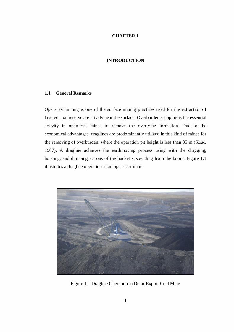
Open-cast mining is one of the surface mining practices used for the extraction of
layered coal reserves relatively near the surface. Overburden stripping is the essential
activity in open-cast mines to remove the overlying formation. Due to the
economical advantages, draglines are predominantly utilized in this kind of mines for
the removing of overburden, where the operation pit height is less than 35 m (Köse,
1987). A dragline achieves the earthmoving process using with the dragging,
hoisting, and dumping actions of the bucket suspending from the boom. Figure 1.1
illustrates a dragline operation in an open-cast mine.
Figure 1.1 Dragline Operation in DemirExport Coal Mine
2
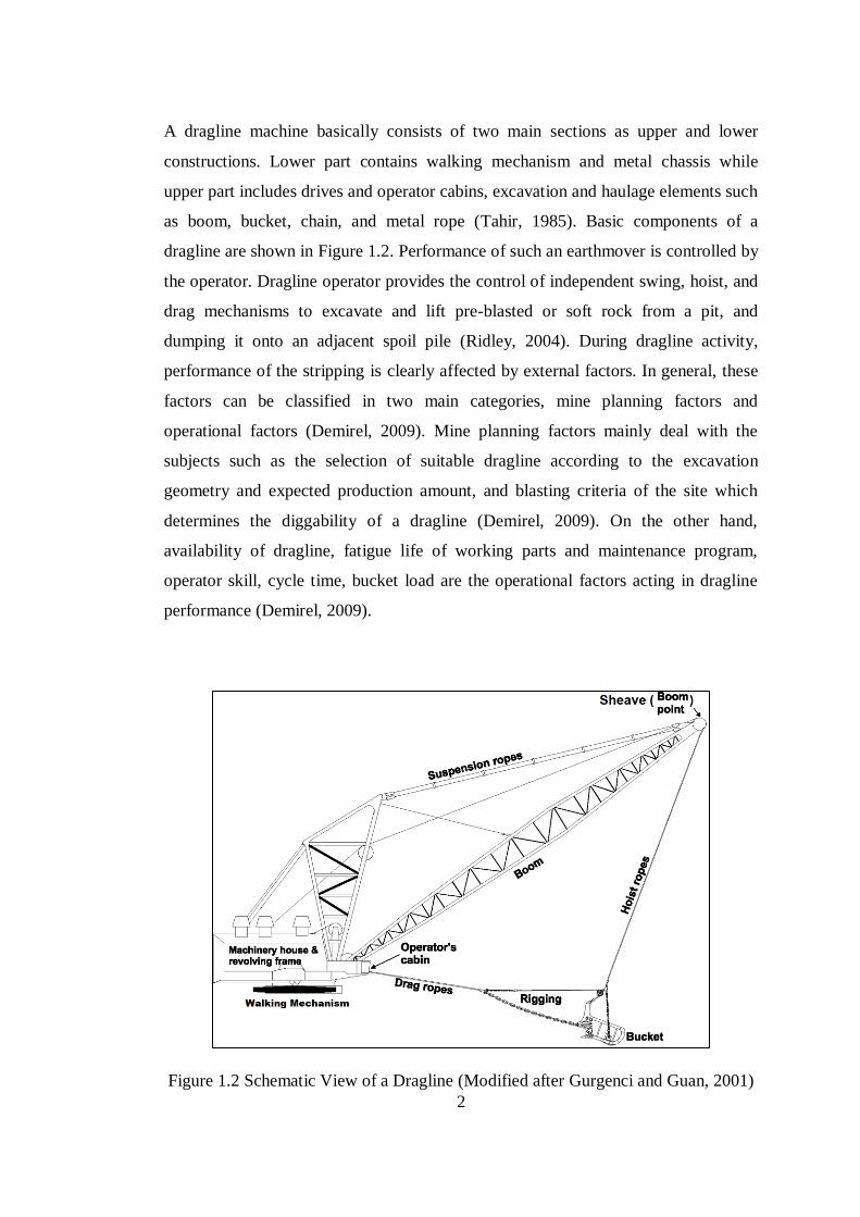
A dragline machine basically consists of two main sections as upper and lower
constructions. Lower part contains walking mechanism and metal chassis while
upper part includes drives and operator cabins, excavation and haulage elements such
as boom, bucket, chain, and metal rope (Tahir, 1985). Basic components of a
dragline are shown in Figure 1.2. Performance of such an earthmover is controlled by
the operator. Dragline operator provides the control of independent swing, hoist, and
drag mechanisms to excavate and lift pre-blasted or soft rock from a pit, and
dumping it onto an adjacent spoil pile (Ridley, 2004). During dragline activity,
performance of the stripping is clearly affected by external factors. In general, these
factors can be classified in two main categories, mine planning factors and
operational factors (Demirel, 2009). Mine planning factors mainly deal with the
subjects such as the selection of suitable dragline according to the excavation
geometry and expected production amount, and blasting criteria of the site which
determines the diggability of a dragline (Demirel, 2009). On the other hand,
availability of dragline, fatigue life of working parts and maintenance program,
operator skill, cycle time, bucket load are the operational factors acting in dragline
performance (Demirel, 2009).
Figure 1.2 Schematic View of a Dragline (Modified after Gurgenci and Guan, 2001)
3
Dragline utilization is common in various open-cast mines in different countries.
Only in America, 101 units of draglines with the bucket capacity ranging from 30 m3
(40 yd3) to 108 m
3 (140 yd
3) are utilized in 56 large open-cast mines and 40% of
overall overburden removing operations in open-cast mines is achieved by the
draglines (Gilewicz, 1999). This percentage is approximately equal to 1.5 billion m3
(1.9 billion yd3)
removed
spoil per year. Following America, Australia (61 units),
South Africa (25 units), Canada (22 units) and India (17 units) are the foremost
countries in dragline utilization. In Turkey, eight units in Turkish Coal Enterprises
and one unit in private sector, a total of nine units of dragline are operated in various
open-cast coal mines. Performance of such a common earthmover, dragline, directly
affects the production schedules in the mines. Detection of the negative factors
during bucket-formation interaction is important for an efficient dragline operation.
In this regard, this research study investigates the mechanical loading simulation of
the bucket during formation cutting process. Main focus in this study is the analysis
of stress-strain components on the bucket during interaction with the formation.
1.2 Statement of the Problem
Walking draglines are massive earthmoving machines which their weights typically
range from 2000 to 7000 tons. They manage the stripping operations with
penetrating, dragging, and hoisting actions of the bucket and carry the overburden
with their booms with a length up to 128 m. During the execution of the procedure,
working elements of dragline are exposed to sudden changes in stress and strain.
These variations can cause fractures, wearings, and fatigue failures in the working
parts of dragline. Especially, investigation of the interaction between formation and
bucket tooth and determination of stress distribution on the bucket and its
components during penetration and dragging processes are critical to estimate the
diggability of dragline and the failure in bucket components. Therefore, modeling
dragline bucket-formation interactions and investigating stress distribution in the
bucket are critical for an efficient excavation.
4
1.3 Objectives and Scope of the Study
The main objective of this study is to investigate the stress and strain distributions in
the dragline bucket induced by the tool-formation interaction and loading conditions.
The elements of the main objective are:
i. To create three-dimensional solid models of dragline bucket and rigging
mechanism in Computer-Aided Design (CAD) software,
ii. To determine formation resistive forces against the bucket action using
earthmoving theories,
iii. To perform a static loading simulation of the three-dimensional model using a
Finite Element Analysis (FEA) software, with the selection of suitable
materials for the bucket elements and realistic loading and boundary
conditions,
iv. To investigate and analyze mechanical effects on the bucket components as
stress and strain, and
v. To identify the sensitivity of stress values to various formation properties.
The scope of this thesis is the investigation of stress and strain components in a solid
model of dragline bucket during horizontal dragging action, with the help of static
analysis in FEA environment. Dynamic finite element analysis of dragline front-end
components is not included within the scope of the study due to the insufficient data
about dragline front-end components.
1.4 Research Methodology
The thesis study was progressed as a combination of analytical approaches to
earthmoving activity, three-dimensional CAD design, and stress-failure analyses in
the FEA environment.
5
The essential components of the research methodology are listed below as:
i. Collection of sketch data to create the solid models of dragline bucket and
rigging mechanism: Technical sketches are formed using available data of
existing bucket in Kangal Demir Export Coal Mine and technical specifications
obtained from dragline spare part catalogues.
ii. Development of solid models for dragline bucket and rigging mechanism: It is
accomplished using Solidworks (Solidworks Co., 2009), a CAD software being
capable of generating sketches, solid parts, and assemblies.
iii. Transferring of the solid models from CAD environment to FEA environment:
Abaqus (Simulia, 6.9-2) is used as the FEA software, which can solve linear or
nonlinear problems. Transfer between the CAD and the FEA software is
managed with the help of Associative Interface for Solidworks, which is an
add-in of Abaqus.
iv. Estimation of the passive earth pressure against the movement of bucket inside
the formation: Since the thesis study aims at investigating stress components in
the bucket during the dragging action, formation counter resistance is found
using the earth cutting theory of Mckyes (1984). Formation specifications in
the theory are taken from the study of Mouazen and Nemenyi (1999), by
authors’ permissions.
v. Simulations of the bucket horizontally cutting the formation: Static simulation
is executed with meshing, material assignment, loading and boundary
condition steps. Two different case studies are carried out. One of them
investigates effect of passive earth pressure on the bucket just before the
movement. Another one is about the observation of the stresses on a bucket
with constant velocity. The cases are repeated for three different formation
specifications.
vi. Visualization of the simulation results: Analysis results are illustrated
according to stress and strain components on the model. Yield points are
detected during the simulation.
vii. Performing sensitivity analysis to identify the formation properties, which
affect the stress values on a dragline bucket element at most.
6
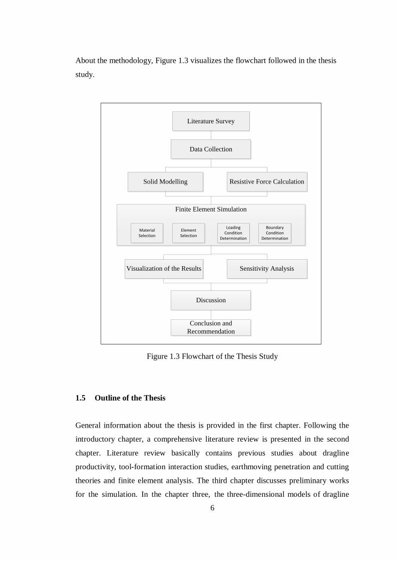
About the methodology, Figure 1.3 visualizes the flowchart followed in the thesis
study.
Solid Modelling
Literature Survey
Data Collection
Resistive Force Calculation
Finite Element Simulation
Material Selection
Element Selection
Loading Condition
Determination
Boundary Condition
Determination
Discussion
Visualization of the Results Sensitivity Analysis
Conclusion and
Recommendation
Figure 1.3 Flowchart of the Thesis Study
1.5 Outline of the Thesis
General information about the thesis is provided in the first chapter. Following the
introductory chapter, a comprehensive literature review is presented in the second
chapter. Literature review basically contains previous studies about dragline
productivity, tool-formation interaction studies, earthmoving penetration and cutting
theories and finite element analysis. The third chapter discusses preliminary works
for the simulation. In the chapter three, the three-dimensional models of dragline
7
bucket and its rigging system in Solidworks CAD software are described in detail.
The fourth chapter mainly focuses on the determination of resistive formation forces
and also implementation of the simulation in Abaqus (Simulia, Version 6.9-2)
environment. In addition, basis of the sensitivity analysis in the study is also
explained in the fourth chapter. Numerical and graphical visualization of simulation
results and discussion parts are the subjects of fifth chapter. The thesis study ends
with the conclusion and recommendation part in the sixth chapter.
8
CHAPTER 2
2 LITERATURE SURVEY
2.1 An Overview of Walking Draglines
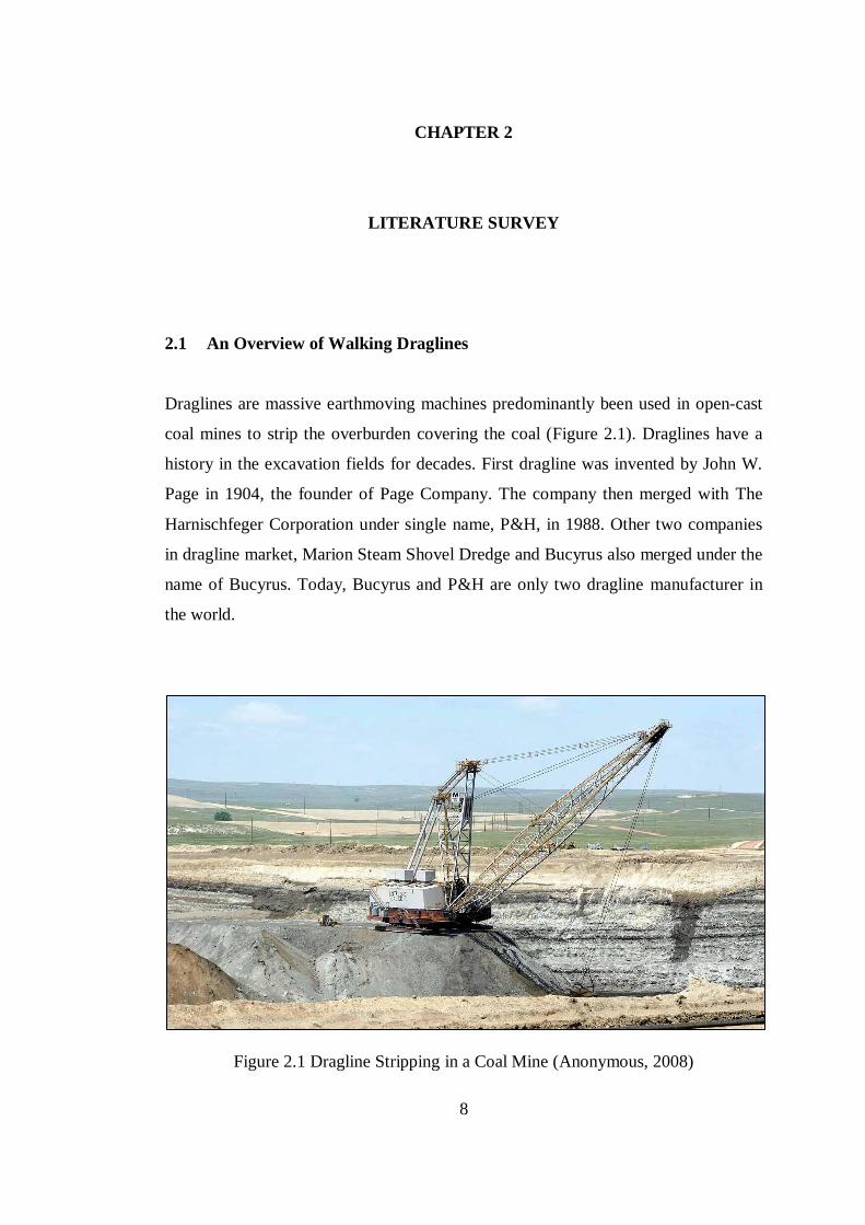
Draglines are massive earthmoving machines predominantly been used in open-cast
coal mines to strip the overburden covering the coal (Figure 2.1). Draglines have a
history in the excavation fields for decades. First dragline was invented by John W.
Page in 1904, the founder of Page Company. The company then merged with The
Harnischfeger Corporation under single name, P&H, in 1988. Other two companies
in dragline market, Marion Steam Shovel Dredge and Bucyrus also merged under the
name of Bucyrus. Today, Bucyrus and P&H are only two dragline manufacturer in
the world.
Figure 2.1 Dragline Stripping in a Coal Mine (Anonymous, 2008)
9
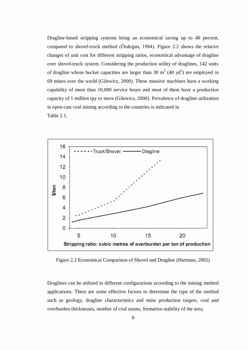
Dragline-based stripping systems bring an economical saving up to 40 percent,
compared to shovel-truck method (Özdoğan, 1984). Figure 2.2 shows the relative
changes of unit cost for different stripping ratios, economical advantage of dragline
over shovel-truck system. Considering the production utility of draglines, 142 units
of dragline whose bucket capacities are larger than 30 m3 (40 yd
3) are employed in
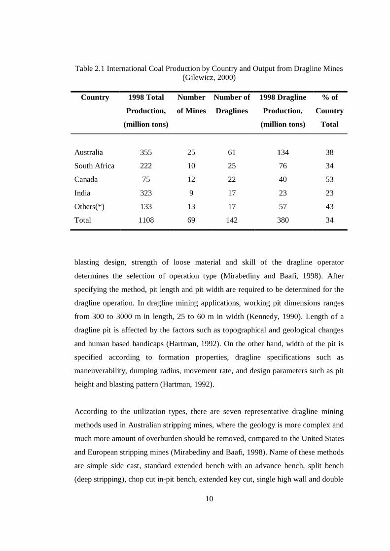
69 mines over the world (Gilewicz, 2000). These massive machines have a working
capability of more than 10,000 service hours and most of them have a production
capacity of 1 million tpy or more (Gilewicz, 2000). Prevalence of dragline utilization
in open-cast coal mining according to the countries is indicated in
Table 2.1.
Figure 2.2 Economical Comparison of Shovel and Dragline (Hartman, 2002)
Draglines can be utilized in different configurations according to the mining method
applications. There are some effective factors to determine the type of the method
such as geology, dragline characteristics and mine production targets, coal and
overburden thicknesses, number of coal seams, formation stability of the area,
10
Table 2.1 International Coal Production by Country and Output from Dragline Mines
(Gilewicz, 2000)
Country 1998 Total
Production,
(million tons)
Number
of Mines
Number of
Draglines
1998 Dragline
Production,
(million tons)
% of
Country
Total
Australia 355 25 61 134 38
South Africa 222 10 25 76 34
Canada 75 12 22 40 53
India 323 9 17 23 23
Others(*) 133 13 17 57 43
Total 1108 69 142 380 34
blasting design, strength of loose material and skill of the dragline operator
determines the selection of operation type (Mirabediny and Baafi, 1998). After
specifying the method, pit length and pit width are required to be determined for the
dragline operation. In dragline mining applications, working pit dimensions ranges
from 300 to 3000 m in length, 25 to 60 m in width (Kennedy, 1990). Length of a
dragline pit is affected by the factors such as topographical and geological changes
and human based handicaps (Hartman, 1992). On the other hand, width of the pit is
specified according to formation properties, dragline specifications such as
maneuverability, dumping radius, movement rate, and design parameters such as pit
height and blasting pattern (Hartman, 1992).
According to the utilization types, there are seven representative dragline mining
methods used in Australian stripping mines, where the geology is more complex and
much more amount of overburden should be removed, compared to the United States
and European stripping mines (Mirabediny and Baafi, 1998). Name of these methods
are simple side cast, standard extended bench with an advance bench, split bench
(deep stripping), chop cut in-pit bench, extended key cut, single high wall and double
11
low wall multi-pass, double high wall and single low wall multi-pass (Mirabediny
and Baafi, 1998). Unlike Australia, tandem dragline method, which allows two
draglines work together, is also applied in European and United States mines. In
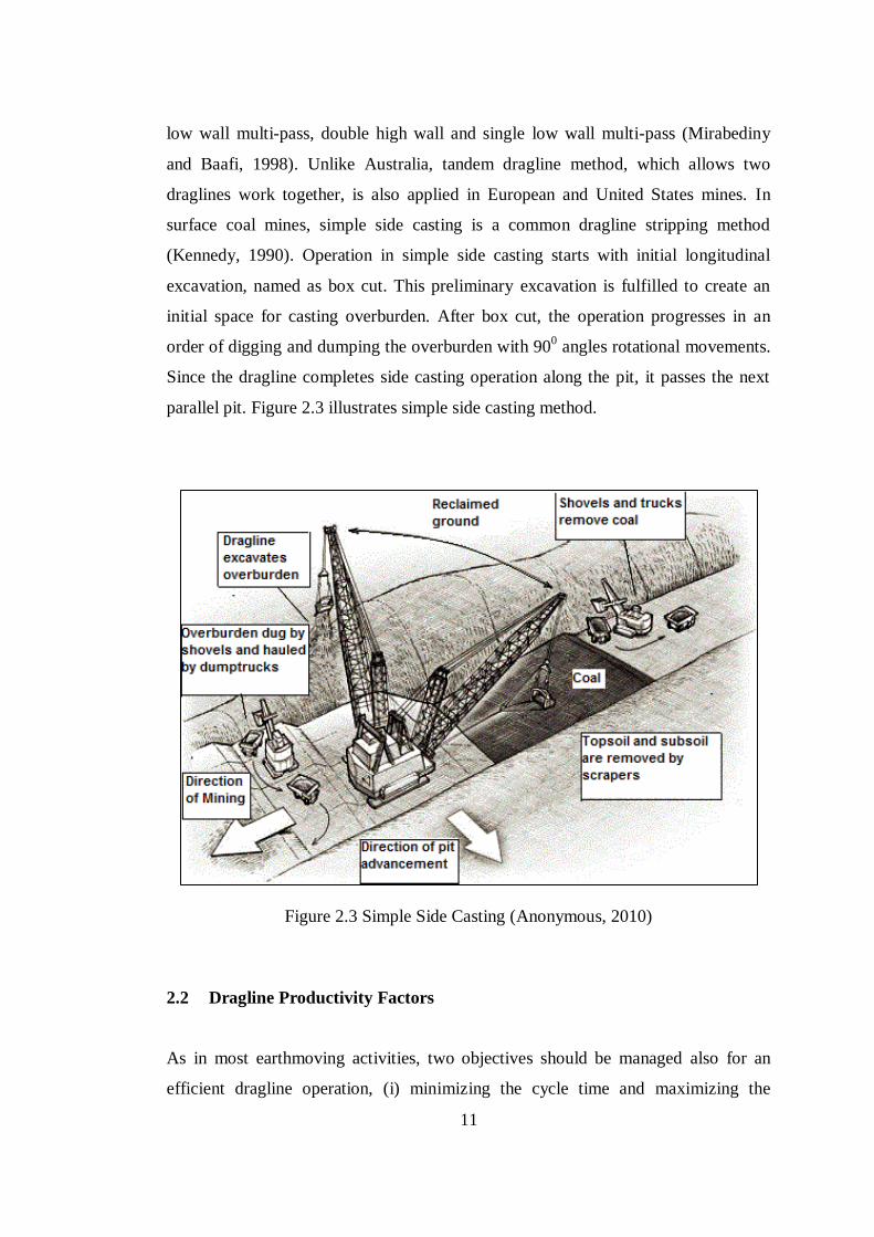
surface coal mines, simple side casting is a common dragline stripping method
(Kennedy, 1990). Operation in simple side casting starts with initial longitudinal
excavation, named as box cut. This preliminary excavation is fulfilled to create an
initial space for casting overburden. After box cut, the operation progresses in an
order of digging and dumping the overburden with 900 angles rotational movements.
Since the dragline completes side casting operation along the pit, it passes the next
parallel pit. Figure 2.3 illustrates simple side casting method.
Figure 2.3 Simple Side Casting (Anonymous, 2010)
2.2 Dragline Productivity Factors
As in most earthmoving activities, two objectives should be managed also for an
efficient dragline operation, (i) minimizing the cycle time and maximizing the
12
number of cycles and (ii) maximizing the payload of bucket (Vynne, 2008).
Therefore, the detection of influential parameters and the related data in both cycle
time and payload are important to criticize the productivity of a dragline operation.
Demirel (2009) gathers these productivity factors into two groups, mine planning and
operational factors. Mine planning and scheduling factors cover the subjects such as
dragline operation geometry, suitability of the dragline for production rate,
economical rehandle excavation volume, blast design satisfying the looseness of the
formation, layering of coal, and bucket selection. On the other hand, operating
factors handle the considerations such as availability of dragline for the operations,
working conditions, suspended load, fatigue life of loading components on a
dragline, cycle time, operator skill, and maintenance program. In this perspective,
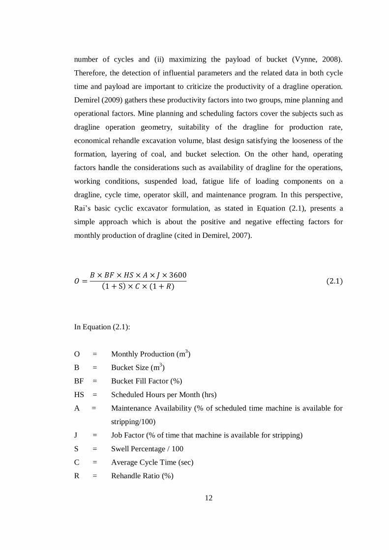
Rai’s basic cyclic excavator formulation, as stated in Equation (2.1), presents a
simple approach which is about the positive and negative effecting factors for
monthly production of dragline (cited in Demirel, 2007).
( ) ( ) ( )
In Equation (2.1):
O = Monthly Production (m3)
B = Bucket Size (m3)
BF = Bucket Fill Factor (%)
HS = Scheduled Hours per Month (hrs)
A = Maintenance Availability (% of scheduled time machine is available for
stripping/100)
J = Job Factor (% of time that machine is available for stripping)
S = Swell Percentage / 100
C = Average Cycle Time (sec)
R = Rehandle Ratio (%)
13
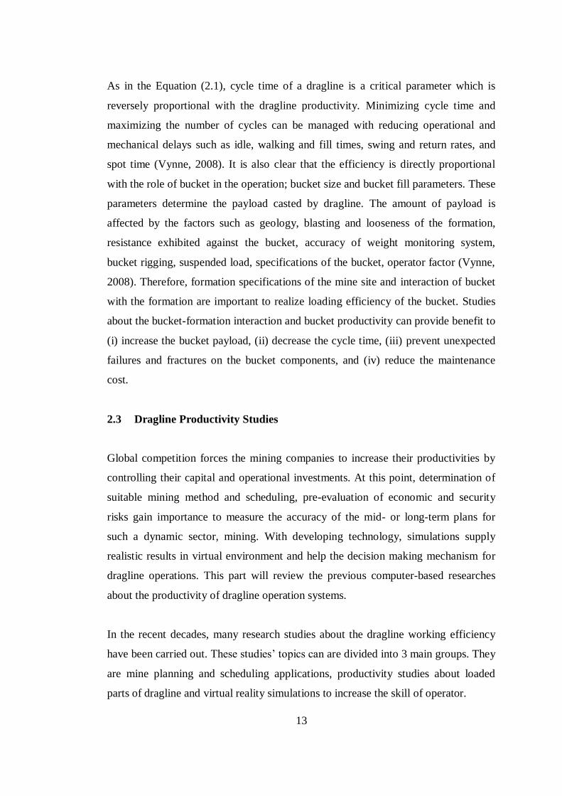
As in the Equation (2.1), cycle time of a dragline is a critical parameter which is
reversely proportional with the dragline productivity. Minimizing cycle time and
maximizing the number of cycles can be managed with reducing operational and
mechanical delays such as idle, walking and fill times, swing and return rates, and
spot time (Vynne, 2008). It is also clear that the efficiency is directly proportional
with the role of bucket in the operation; bucket size and bucket fill parameters. These
parameters determine the payload casted by dragline. The amount of payload is
affected by the factors such as geology, blasting and looseness of the formation,
resistance exhibited against the bucket, accuracy of weight monitoring system,
bucket rigging, suspended load, specifications of the bucket, operator factor (Vynne,
2008). Therefore, formation specifications of the mine site and interaction of bucket
with the formation are important to realize loading efficiency of the bucket. Studies
about the bucket-formation interaction and bucket productivity can provide benefit to
(i) increase the bucket payload, (ii) decrease the cycle time, (iii) prevent unexpected
failures and fractures on the bucket components, and (iv) reduce the maintenance
cost.
2.3 Dragline Productivity Studies
Global competition forces the mining companies to increase their productivities by
controlling their capital and operational investments. At this point, determination of
suitable mining method and scheduling, pre-evaluation of economic and security
risks gain importance to measure the accuracy of the mid- or long-term plans for
such a dynamic sector, mining. With developing technology, simulations supply
realistic results in virtual environment and help the decision making mechanism for
dragline operations. This part will review the previous computer-based researches
about the productivity of dragline operation systems.
In the recent decades, many research studies about the dragline working efficiency
have been carried out. These studies’ topics can are divided into 3 main groups. They
are mine planning and scheduling applications, productivity studies about loaded
parts of dragline and virtual reality simulations to increase the skill of operator.
14
2.3.1 Dragline Productivity Studies through Mine Planning and Working
Schedules
Computer-based studies have been performed to utilize in short-, mid- or long-term
dragline mining plans and schedules, for decades. At one of them, Baafi et al. (1997)
developed an integrated computer simulation model with DSLX computer language,
to optimize the dragline operations. Three-dimensional geological model, assisted by
a geological database, was formed. Complex multi-seam operations and distinct
dragline methods were claimed to be scheduled and simulated in the model.
Moreover, Erdem et al. (1998) searched about the synchronization of tandem
dragline operation system, time management for operating and idle times of the two
draglines and its effect on the efficiency of total operation. The draglines were
denominated as dependent and independent dragline. Independent dragline was the
free one in its advance way. The model aimed to reduce unoperated time of both
dependent and independent draglines and to satisfy the synchronization between each
other. In another study, Erdem et al. (2004) studied on a three-dimensional
computational model assisting to choose optimal dragline digging mode for direct
side-casting method. According to the hierarchical structure of the model, the
program initiated with the determination of the spoil type depending on the coal
seam inclination. Then, it progressed with the identification of spoil placement such
as Dump-Near-Set (DNS) and Dump-Near-Dig (DND). By the execution of the
model, several pit configurations could be obtained for a dragline by changing pit
width values. In addition, Erdem et al. (2005) handled the simulation of three
fundamental dragline stripping techniques; box cut opening, direct side casting and
extended benching. In the research, it was tried to investigate the effects of
overlapping cones on spoil geometry along the direction of both dragline advance
and mining advance. Furthermore, Genç (2006) performed a research about dragline
operations in Western Anatolia. During the study, single dragline, tandem dragline
and dragline-shovel-truck combinations were compared according to cost/capacity
relationships. Dragline methods in Western Anatolia Pits were illustrated with three-
dimensional animations. Productivity of dragline was tried to calculate numerically
with the help of working parameters. Also, Cobcroft (2007) performed a virtual
15
reality program. It was indicated that this program was practically used in Australian
open-cast mines to organize short-, mid-, long-term mine plans. It was claimed that
program had the ability to combine truck-excavator, dragline and bulldozer
operations and optimize the overall mine plan in the field. In addition, it was stated
that the program could provide cycle time of dragline, maximum excavation depth of
dragline, maximum spoil height, and volumetric calculations for stripping rate.
2.3.2 Dragline Productivity Studies through Operator Training
Another investigation field for dragline productivity is about the training of dragline
operator in a virtual excavation environment. Training of an inexperienced operator
is not a simple work. It is required a six-month training to bring a dragline operator
to a proficient level (Corke et al., 2006). This situation can cause a time loss and
financial loss up to 2500 $/hour (Williams, 1997). Moreover, such an operator can
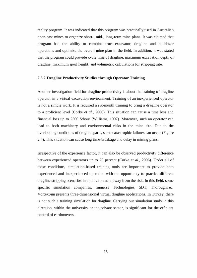
lead to both machinery and environmental risks in the mine site. Due to the
overloading conditions of dragline parts, some catastrophic failures can occur (Figure
2.4). This situation can cause long time-breakage and delay in mining plans.
Irrespective of the experience factor, it can also be observed productivity difference
between experienced operators up to 20 percent (Corke et al., 2006). Under all of
these conditions, simulation-based training tools are important to provide both
experienced and inexperienced operators with the opportunity to practice different
dragline stripping scenarios in an environment away from the risk. In this field, some
specific simulation companies, Immerse Technologies, 5DT, ThoroughTec,
VortexSim presents three-dimensional virtual dragline applications. In Turkey, there
is not such a training simulation for dragline. Carrying out simulation study in this
direction, within the university or the private sector, is significant for the efficient
control of earthmovers.
16
Figure 2.4 Dragline Boom Failure (Davis, 2010)
2.3.3 Dragline Productivity Studies through Improving Machinery Parts
Third common search topic for the dragline productivity is about the front-end parts
of dragline during excavation and their effects over the productivity. A dragline is an
earthmover which is operated with its long and heavy boom in a range of curvilinear
area. Different amounts of forces and inertias are applied to distinct parts of machine
during digging, hoisting, revolving and dumping cycles. Ideally, dragline should be
controlled so that maximum amount of payload could be carried within minimum
cycle time without catastrophic failure or damages on the mechanism. Since these
types of failures and damages can cause long-term breaks and loss of time and
production, the investigation and simulation of the loaded parts of dragline are
critical to analyze their effects over the dragline performance. Several studies for
different components of dragline have been practiced in recent years. These
researches mostly concentrate on the topics about boom structure, rigging
mechanism, bucket, and its apparatus.
17
In a study about dragline booms, Dayawansa et al. (2006) described stress and
failures in the weld joints of the booms. A solid model of the boom was created,
which was made of structural tubular elements. Three-dimensional stress analysis of
the boom components was performed. Effective forces on the boom were detected,
which appeared due to the self-weight of boom, weight of the bucket acting through
the hoist ropes, suspension ropes, and the inertia of angular accelerations. In the
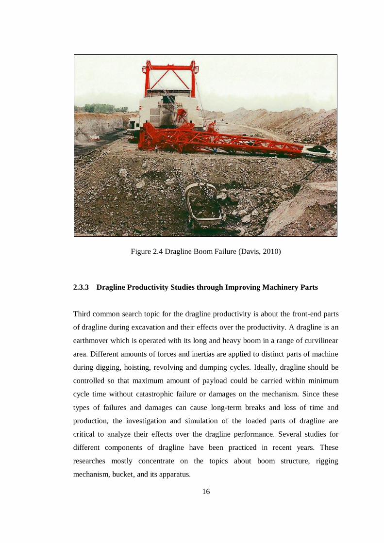
study, crack propagation in the boom was investigated. In another research, Demirel
(2007) modeled the front-end assembly of dragline with dynamic and kinematic
variables in order to find maximum loads over the parts and yield stress of the boom.
Figure 2.5 illustrates the two-dimensional vector loop presentation of the front-end
assembly, used in the analysis of stress values during hoisting and dragging of the
bucket and rotation of boom. Discrete Element Method (DEM) and Simultaneous
Constraints Method were used to formulate the kinematics of dragline and bucket-
material interactions, respectively.
Figure 2.5 Dragline Kinematics (a) Dragline Front-End Assembly (b) Vector Loop
Presentation (Modified after Demirel, 2007)
In addition to dragline boom, researches about dragline bucket and rigging system
are equally critical, since dragline contacts the formation with the help of bucket.
Draglines make overburdening operation with their large earth digging buckets, some
of which can remove earth more than 108 m3 (140 yd
3) at once (Gilewicz, 1999). The
18
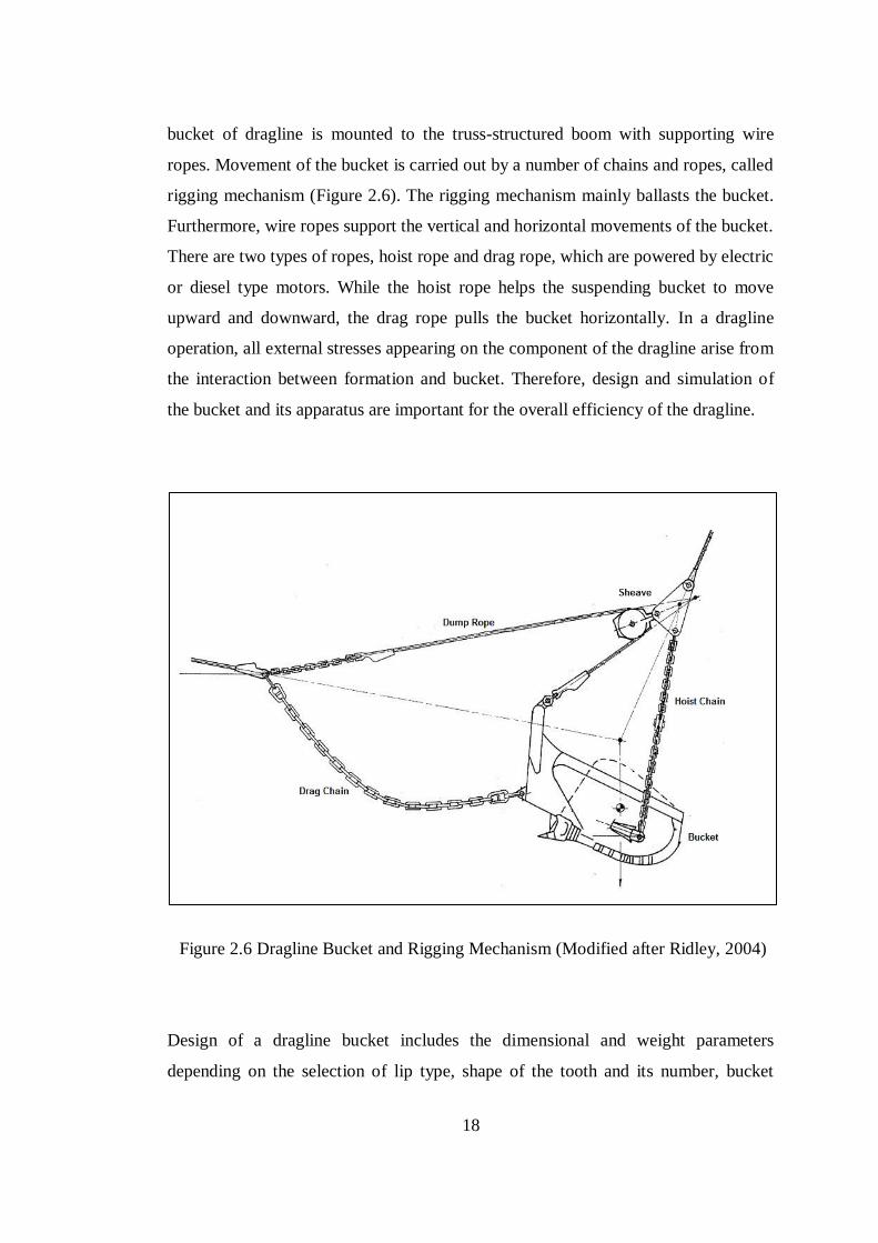
bucket of dragline is mounted to the truss-structured boom with supporting wire
ropes. Movement of the bucket is carried out by a number of chains and ropes, called
rigging mechanism (Figure 2.6). The rigging mechanism mainly ballasts the bucket.
Furthermore, wire ropes support the vertical and horizontal movements of the bucket.
There are two types of ropes, hoist rope and drag rope, which are powered by electric
or diesel type motors. While the hoist rope helps the suspending bucket to move
upward and downward, the drag rope pulls the bucket horizontally. In a dragline
operation, all external stresses appearing on the component of the dragline arise from
the interaction between formation and bucket. Therefore, design and simulation of
the bucket and its apparatus are important for the overall efficiency of the dragline.
Figure 2.6 Dragline Bucket and Rigging Mechanism (Modified after Ridley, 2004)
Design of a dragline bucket includes the dimensional and weight parameters
depending on the selection of lip type, shape of the tooth and its number, bucket
19
rigging mechanism, and it affects the overall productivity of dragline operation
(Özdoğan, 2003) Therefore, many research studies have been carried out to improve
the bucket and rigging system of dragline. Ridley and Algra (2004) classified the
investigations about the productivity studies for bucket and rigging mechanism into
four main groups: Optimization of bucket filling, improvement of rigging system,
testing of bucket kinematically, and automation of scooping.
About the bucket filling, O’Beirne (1997) tried to find the effects of changes on
rigging mechanism in the bucket efficiency. Within the scope of the investigation,
differences between rigging system utilizations in Australian mines, influences of
rigging parts such as hoist rope, dump rope, chain for the bucket efficiency were
analysed. Moreover, Kavetsky (1999) developed a computational tool to use in the
design and optimization of bucket and rigging system. Some computational modules
were created to prepare a CAD environment for bucket design, to create two-
dimensional bucket and rigging mechanism models, to determine material particle
specifications, and to validate and display the program results. In another dragline
bucket productivity investigation, Townson (2001) searched the optimization bucket
payload of dragline. To achieve this, different mechanical and finite element models
were created and it was validated with site test measurements of a Bucyrus type
dragline. In the study, it was aimed to analyze the relationship between bucket filling
and idle time which occurs due to the high wearing. As an example to the
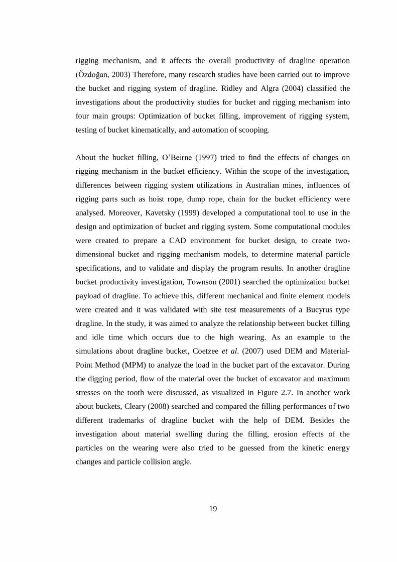
simulations about dragline bucket, Coetzee et al. (2007) used DEM and Material-
Point Method (MPM) to analyze the load in the bucket part of the excavator. During
the digging period, flow of the material over the bucket of excavator and maximum
stresses on the tooth were discussed, as visualized in Figure 2.7. In another work
about buckets, Cleary (2008) searched and compared the filling performances of two
different trademarks of dragline bucket with the help of DEM. Besides the
investigation about material swelling during the filling, erosion effects of the
particles on the wearing were also tried to be guessed from the kinetic energy
changes and particle collision angle.
20
Figure 2.7 Shear Zone Theory at Different Displacements (Coetzee, 2007)
As relevant with the improvement of rigging system, Rowlands (2000) informed
about universal rigging system which is different from the conventional rigging with
its distinct hoisting rope configuration. A dragline prototype with a 1:250 scale was
tested for this purpose. After experiments, it was observed that universal rigging
system provides benefits with a decrease in capital cost of rigging components, cost
of installation, duration of idle time, and an increase in possible dumping height and
chopping reach. It was also claimed that this system was able to limit the transient
forces on the dragline with its semi-automatic control. Moreover, Meyers and Leslie
(2001) worked about the effects of the pivot point variations of an universal rigging
mechanism, drag, front hoist, and rear hoist points, over the performance of bucket.
In the study, total mass reduction and new mass distribution of both bucket and
payload, load variations according to new configurations of ropes were discussed and
performances of conventional rigging and universal rigging were compared.
Concerning with the kinematics of the dragline bucket, Srour (1999) claimed that it
was created a simulation model identifying bucket and its rigging system with the
help of a data set. It was expressed that this model had the ability to solve non-linear
equations for the static balance of the bucket and rigging. It was also stated that
21
the model could assess the carrying angle and static force distribution on the system
when any change about the bucket and rigging mechanism was introduced to the
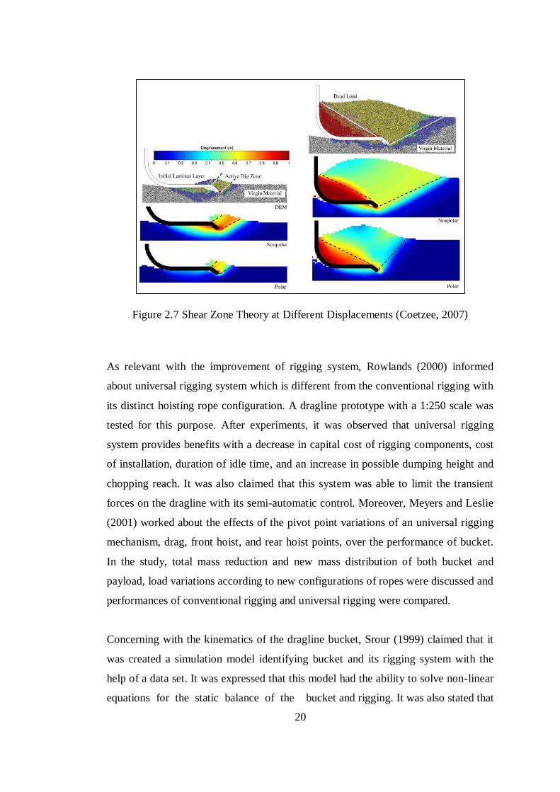
model. Furthermore, Ridley et al. (2004) tried to explain the bucket and rigging
dynamics of dragline with a numerical model and simplified laboratory experiments.
In the study, dynamic model was described the perturbation of the bucket from static
equilibrium. Static pose of dragline bucket and rigging with a contour set of equal
bucket carry angle was defined as in Figure 2.8. Initial angular accelerations were
determined with the help of hoist and drag rope tensions and this static load. After
computation process, solutions of the numerical model were compared to the
experimental results.
Figure 2.8 Dragline Layout Showing Constant Carry Angle Contours (Ridley, 2004)
About the automation of dragline, Lever and McAree (2003) aimed to draw a
roadmap for determining the requirements of the scooping automation in open-cast
mines. In this perspective, topics were detected and surveyed to enhance the
productivity and to reduce the number of failures with the help of advance sensor
technology, mine-wide information system, existing sensor systems on the sites.
22
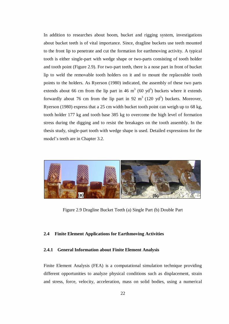
In addition to researches about boom, bucket and rigging system, investigations
about bucket teeth is of vital importance. Since, dragline buckets use teeth mounted
to the front lip to penetrate and cut the formation for earthmoving activity. A typical
tooth is either single-part with wedge shape or two-parts consisting of tooth holder
and tooth point (Figure 2.9). For two-part teeth, there is a nose part in front of bucket
lip to weld the removable tooth holders on it and to mount the replaceable tooth
points to the holders. As Ryerson (1980) indicated, the assembly of these two parts
extends about 66 cm from the lip part in 46 m3 (60 yd
3) buckets where it extends
forwardly about 76 cm from the lip part in 92 m3
(120 yd3) buckets. Moreover,
Ryerson (1980) express that a 25 cm width bucket tooth point can weigh up to 68 kg,
tooth holder 177 kg and tooth base 385 kg to overcome the high level of formation
stress during the digging and to resist the breakages on the tooth assembly. In the
thesis study, single-part tooth with wedge shape is used. Detailed expressions for the
model’s teeth are in Chapter 3.2.
Figure 2.9 Dragline Bucket Teeth (a) Single Part (b) Double Part
2.4 Finite Element Applications for Earthmoving Activities
2.4.1 General Information about Finite Element Analysis
Finite Element Analysis (FEA) is a computational simulation technique providing
different opportunities to analyze physical conditions such as displacement, strain
and stress, force, velocity, acceleration, mass on solid bodies, using a numerical
23
identification called finite element. FEA drives complex configurations of points
named as node. It generates adjoining grids named as mesh, using the nodes. The
mesh has a network formation where each adjacent node is connected to each other.
This mesh network involves material and structural specifications in order to identify
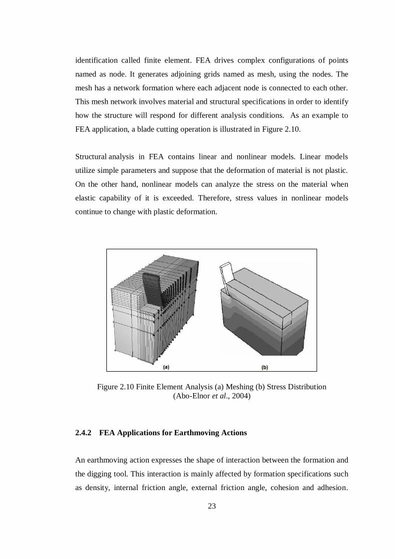
how the structure will respond for different analysis conditions. As an example to
FEA application, a blade cutting operation is illustrated in Figure 2.10.
Structural analysis in FEA contains linear and nonlinear models. Linear models
utilize simple parameters and suppose that the deformation of material is not plastic.
On the other hand, nonlinear models can analyze the stress on the material when
elastic capability of it is exceeded. Therefore, stress values in nonlinear models
continue to change with plastic deformation.
Figure 2.10 Finite Element Analysis (a) Meshing (b) Stress Distribution
(Abo-Elnor et al., 2004)
2.4.2 FEA Applications for Earthmoving Actions
An earthmoving action expresses the shape of interaction between the formation and
the digging tool. This interaction is mainly affected by formation specifications such
as density, internal friction angle, external friction angle, cohesion and adhesion.
24
Earthmoving factors form a very complex phenomenon. Since, formation can exhibit
either isotropic or anisotropic behavior. If it is anisotropic, formation specifications
change largely with the direction of effective forces inside the formation, and it is
hard to estimate such a behavior. Moreover, it is clear that compactness of the
formation can fully change the formation manner on the digging tool. All dynamics
of the formation are required to be known to see the full interaction between tool and
formation. However, it is hard to identify complete effect of the formation on the
tool. Under these conditions, it is better to characterize the tool-formation interaction
most closely to the reality, with some assumptions.
Dealing with the bucket moving into the formation, different types of questions can
be investigated. In literature, researches about the bucket utilization are divided into
the topic as the settlement and movement of the formation, forces exerted during
sweeping, amount of filling into the bucket, and resistive forces of formation against
the tool. Because of its complexity, simple analytical models cannot answer to such
problems. Computational integrations can be required to evaluate these earthmoving
actions.
Above mentioned topics can be solved by utilizing FEA. It yields a technique to
model systems consisting of many differential elements. Many investigators have
used FEA to address issues related to earthmoving actions. At one them, Yong and
Hanna (1977) worked about productivity of a flat blade moving in clay formation for
a distances smaller than one foot. It was claimed that they improved a method that
presents particular information about the stress and deformation of the formation due
to the excavation forces. It was stated that the method provided benefit at the
estimation of forces exerted by both the tool and the formation. Mounem and
Nemenyi (1999) created an elastic-perfectly plastic formation model and used FEA
to simulate the formation cutting process of a subformation with different
geometries. Fielke (1999) performed a computational model expressing the effect of
cutting edge geometry over the tillage forces. This two dimensional finite element
model was supported by the experiment findings. Mootaz et al. (2003) performed the
three-dimensional simulation of narrow blade-formation interaction in a FEA solver,
25
by assuming that formation behaves elastic. They verified formation failure zones
vertically and horizontally to eliminate convergence problem induced because of
large blade movement. The model was validated by providing the ultimate shear
stress zones in the formation after computing the software and matching it with the
predefined formation failure areas. In a two dimensional approach, Davoudi et al.
(2008) insisted that a model which is capable of estimating draft forces during tillage
was created in FEA software. Moreover, in many research, brittle behavior and
plasticity of formation during the cutting process was analyzed (Chi and Kushwaha,
1989; Raper and Erbach, 1990; Aluko and Chandler, 2004; Aluko, 2008).
Besides FEA, the reader can prefer to investigate DEM for the tool-formation
interaction modeling, while it is specifically good for the simulation of granular
materials and for analyzing the relationship between inter-particle and particle-tool
behaviors (Cleary, 1998; Owen et al., 2002; Hofstetter, 2002).
2.5 Earthmoving Action of a Dragline Bucket within the Formation
An earthmover performs two main earth digging mechanisms such as cutting and
penetration, according to their digging tool geometries and/or formation
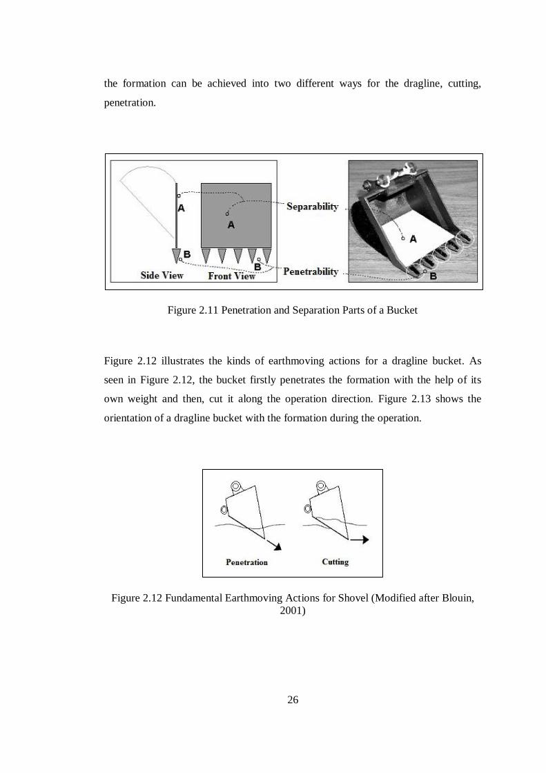
displacement abilities. When the shape of the digging tool is handled, a bucket
mainly consists of two parts as shown in Figure 2.11. Initially, a bucket has a
rectangular shape floor component, named as the separation plate as stated with A in
Figure 2.11. With the help of this plate, a bucket is able to move the formation by
pushing or dragging (dragline bucket) it to the failure state. Secondly, the bucket has
another mechanical component, teeth, as stated with B in Figure 2.11. Bucket teeth
penetrate the formation media to relieve digging mechanism.
Dragline buckets are common overburden stripping tools used in the open-cast
mines. In a dragline, chain and rope combination gives axial motion to the bucket
and determine the digging direction. The motional varieties provide the earthmover
fully benefit from the separating and penetration ability of the bucket. Depending on
the interaction conditions between bucket tips and the formation, the movements into
26
the formation can be achieved into two different ways for the dragline, cutting,
penetration.
Figure 2.11 Penetration and Separation Parts of a Bucket
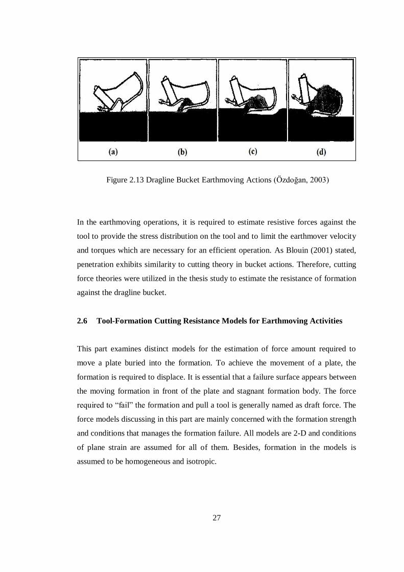
Figure 2.12 illustrates the kinds of earthmoving actions for a dragline bucket. As
seen in Figure 2.12, the bucket firstly penetrates the formation with the help of its
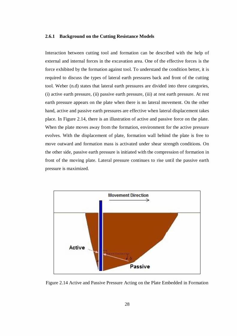
own weight and then, cut it along the operation direction. Figure 2.13 shows the
orientation of a dragline bucket with the formation during the operation.
Figure 2.12 Fundamental Earthmoving Actions for Shovel (Modified after Blouin,
2001)
27
Figure 2.13 Dragline Bucket Earthmoving Actions (Özdoğan, 2003)
In the earthmoving operations, it is required to estimate resistive forces against the
tool to provide the stress distribution on the tool and to limit the earthmover velocity
and torques which are necessary for an efficient operation. As Blouin (2001) stated,
penetration exhibits similarity to cutting theory in bucket actions. Therefore, cutting
force theories were utilized in the thesis study to estimate the resistance of formation
against the dragline bucket.
2.6 Tool-Formation Cutting Resistance Models for Earthmoving Activities
This part examines distinct models for the estimation of force amount required to
move a plate buried into the formation. To achieve the movement of a plate, the
formation is required to displace. It is essential that a failure surface appears between
the moving formation in front of the plate and stagnant formation body. The force
required to “fail” the formation and pull a tool is generally named as draft force. The
force models discussing in this part are mainly concerned with the formation strength
and conditions that manages the formation failure. All models are 2-D and conditions
of plane strain are assumed for all of them. Besides, formation in the models is
assumed to be homogeneous and isotropic.
28
2.6.1 Background on the Cutting Resistance Models
Interaction between cutting tool and formation can be described with the help of
external and internal forces in the excavation area. One of the effective forces is the
force exhibited by the formation against tool. To understand the condition better, it is
required to discuss the types of lateral earth pressures back and front of the cutting
tool. Weber (n.d) states that lateral earth pressures are divided into three categories,
(i) active earth pressure, (ii) passive earth pressure, (iii) at rest earth pressure. At rest
earth pressure appears on the plate when there is no lateral movement. On the other
hand, active and passive earth pressures are effective when lateral displacement takes
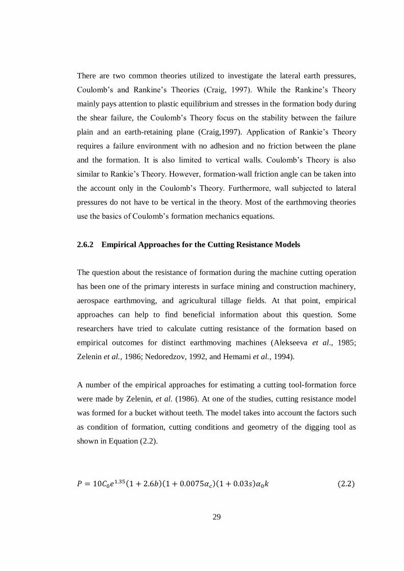
place. In Figure 2.14, there is an illustration of active and passive force on the plate.
When the plate moves away from the formation, environment for the active pressure
evolves. With the displacement of plate, formation wall behind the plate is free to
move outward and formation mass is activated under shear strength conditions. On
the other side, passive earth pressure is initiated with the compression of formation in
front of the moving plate. Lateral pressure continues to rise until the passive earth
pressure is maximized.
Figure 2.14 Active and Passive Pressure Acting on the Plate Embedded in Formation
29
There are two common theories utilized to investigate the lateral earth pressures,
Coulomb’s and Rankine’s Theories (Craig, 1997). While the Rankine’s Theory
mainly pays attention to plastic equilibrium and stresses in the formation body during
the shear failure, the Coulomb’s Theory focus on the stability between the failure
plain and an earth-retaining plane (Craig,1997). Application of Rankie’s Theory
requires a failure environment with no adhesion and no friction between the plane
and the formation. It is also limited to vertical walls. Coulomb’s Theory is also
similar to Rankie’s Theory. However, formation-wall friction angle can be taken into
the account only in the Coulomb’s Theory. Furthermore, wall subjected to lateral
pressures do not have to be vertical in the theory. Most of the earthmoving theories
use the basics of Coulomb’s formation mechanics equations.
2.6.2 Empirical Approaches for the Cutting Resistance Models
The question about the resistance of formation during the machine cutting operation
has been one of the primary interests in surface mining and construction machinery,
aerospace earthmoving, and agricultural tillage fields. At that point, empirical
approaches can help to find beneficial information about this question. Some
researchers have tried to calculate cutting resistance of the formation based on
empirical outcomes for distinct earthmoving machines (Alekseeva et al., 1985;
Zelenin et al., 1986; Nedoredzov, 1992, and Hemami et al., 1994).
A number of the empirical approaches for estimating a cutting tool-formation force
were made by Zelenin, et al. (1986). At one of the studies, cutting resistance model
was formed for a bucket without teeth. The model takes into account the factors such
as condition of formation, cutting conditions and geometry of the digging tool as
shown in Equation (2.2).
( )( )( ) ( )
30
In Equation (2.2), is cutting resistance, is compactness coefficient, is cutting
depth in cms, is bucket width in m, is angle of cutting in degrees, is bucket
cutting surface thickness in cms, is tip angle coefficient, is cutting-type
coefficient.
In empirical models, different types of indices are suggested based on the system of
earthmoving machines and resistive forces existing between the formation and the
machine. They can be approximately predicted by quantitative basic equations. Since
this type of model generally aims to offer analytical tools for machine design, it is
not obvious how to infer for random mechanisms and formation conditions. Even
though the empirical models predict the earth-moving resistance of the formation,
they are lack of representing the process of excavation. Analytical approaches were
utilized instead of empirical models to calculate the earth-cutting force of dragline
bucket due to:
i. They are not analytical models so they are not fully capable of providing the
needs of earth-moving simulations. For instance, it is hard to obtain how to
embody a case in the formula where an overburden is located on the top of the
expected cutting zone.
ii. It is not clear what types of resisting force base are involved in the empirical
model.
iii. The models are not referred in terms of general geotechnical parameters such
as internal friction angle (φ) and cohesion (c). This terminological usage is
required to reflect formation properties to the model correctly.
iv. Since the models depend on experimental outcomes, the validity of the models
is directly related to how the estimated formulations resemble the original
experiment conditions.
2.6.3 Analytical Approaches for the Cutting Resistance Models
Models used for the force estimation in earth-moving activities aim to find
mathematical approaches for the counter force behavior of formation on the moving
31
tool. These models can be divided into 3 main categories according to the types of
the earth-moving activities, penetration, cutting, and loading. Draglines perform the
excavation operations with dragging, hoisting, and swing functions. It cuts the
formation with its dragging function. Therefore, resistive force models for the cutting
action are critical to estimate the stresses over the bucket.
In this perspective, Blouin et al. (2001) presented a review study about the force
prediction models for earth-moving tasks. In the review, it was emphasized that
three-dimensional cutting models are apart from the two-dimensional cutting models
with their side effect factors. However, Blouin et al. (2001) also stated that there is
negligible relationship between side effect findings of analytical three-dimensional
models and those of a real bucket and Blouin et al. (2001) also indicated that it can
be utilized from two-dimensional models in force calculation of bucket digging
process. Therefore, two-dimensional models will be analyzed and discussed under
this title.
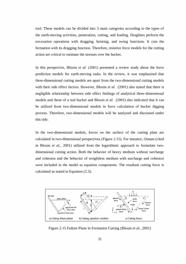
In the two-dimensional models, forces on the surface of the cutting plate are
calculated in two-dimensional perspectives (Figure 2.15). For instance, Osman (cited
in Blouin et al., 2001) utilized from the logarithmic approach to formulate two-
dimensional cutting action. Both the behavior of heavy medium without surcharge
and cohesion and the behavior of weightless medium with surcharge and cohesion
were included in the model as equation components. The resultant cutting force is
calculated as stated in Equation (2.3).
Figure 2.15 Failure Plane in Formation Cutting (Blouin et al., 2001)
32
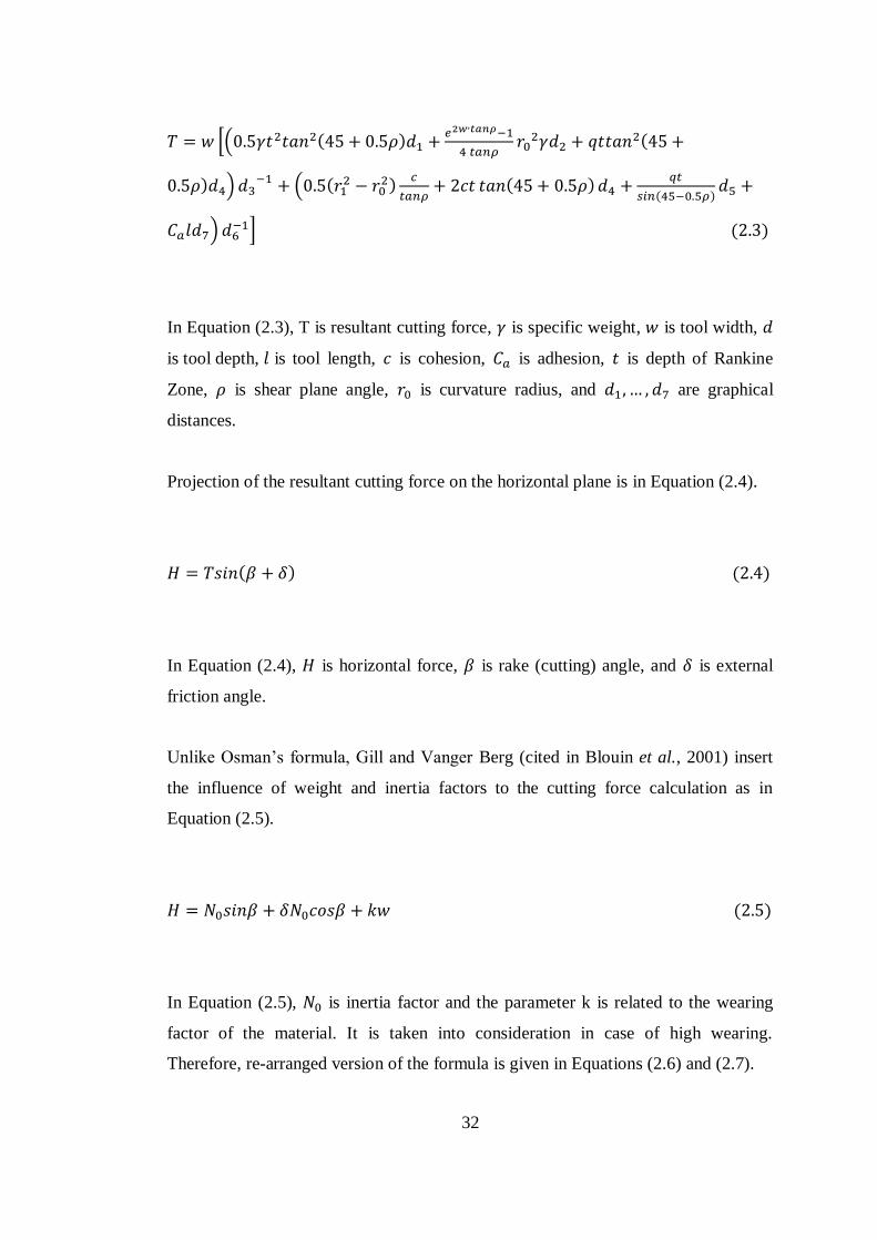
*( ( )
(
) ) ( (
)
( )
( )
) + ( )
In Equation (2.3), T is resultant cutting force, is specific weight, is tool width,
is tool depth, is tool length, is cohesion, is adhesion, is depth of Rankine
Zone, is shear plane angle, is curvature radius, and are graphical
distances.
Projection of the resultant cutting force on the horizontal plane is in Equation (2.4).
( ) ( )
In Equation (2.4), is horizontal force, is rake (cutting) angle, and is external
friction angle.
Unlike Osman’s formula, Gill and Vanger Berg (cited in Blouin et al., 2001) insert
the influence of weight and inertia factors to the cutting force calculation as in
Equation (2.5).
( )
In Equation (2.5), is inertia factor and the parameter k is related to the wearing
factor of the material. It is taken into consideration in case of high wearing.
Therefore, re-arranged version of the formula is given in Equations (2.6) and (2.7).
33
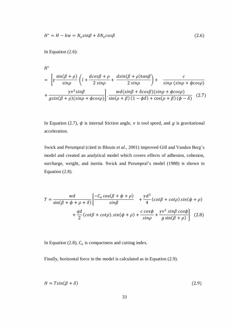
( )
In Equation (2.6):
* ( )
(
( )
)
( )
( )( )+
( )( )
( ) ( ) ( ) ( ) ( )
In Equation (2.7), is internal friction angle, is tool speed, and is gravitational
acceleration.
Swick and Perumpral (cited in Blouin et al., 2001) improved Gill and Vanden Berg’s
model and created an analytical model which covers effects of adhesion, cohesion,
surcharge, weight, and inertia. Swick and Perumpral’s model (1988) is shown in
Equation (2.8).
( )* ( )
( ) ( )
( ) ( )
( )+ ( )
In Equation (2.8), is compactness and cutting index.
Finally, horizontal force in the model is calculated as in Equation (2.9).
( ) ( )
34
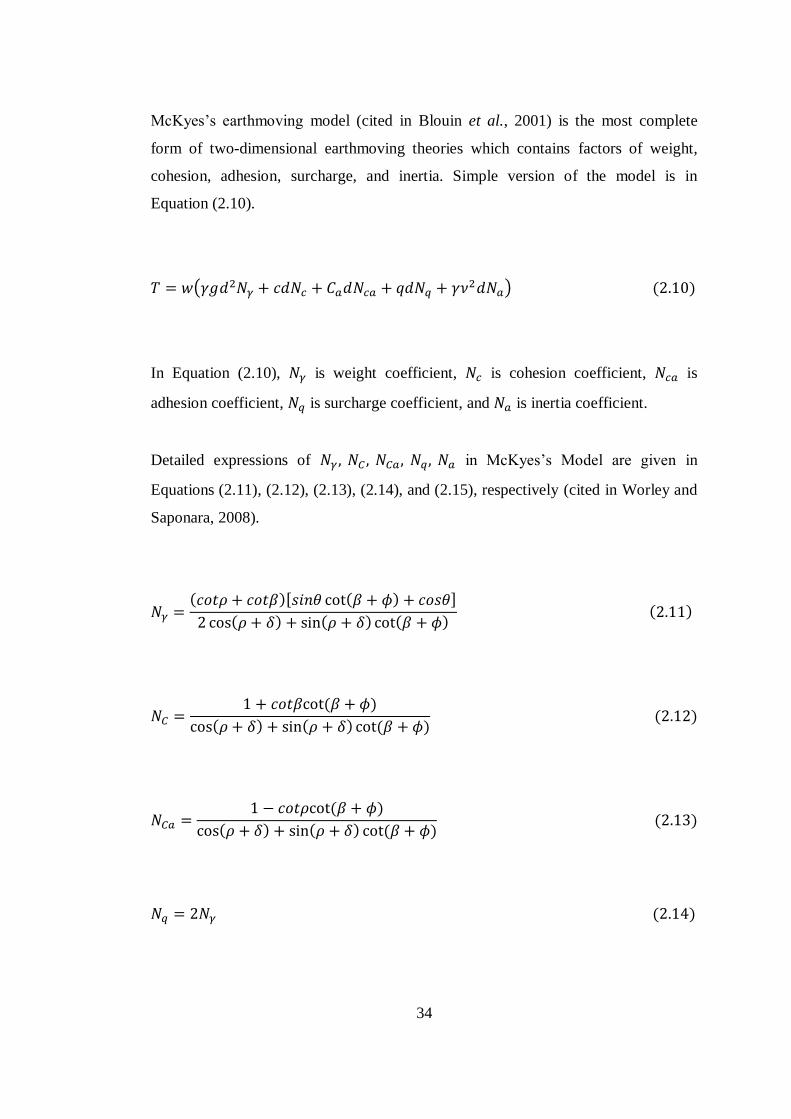
McKyes’s earthmoving model (cited in Blouin et al., 2001) is the most complete
form of two-dimensional earthmoving theories which contains factors of weight,
cohesion, adhesion, surcharge, and inertia. Simple version of the model is in
Equation (2.10).
( ) ( )
In Equation (2.10), is weight coefficient, is cohesion coefficient, is
adhesion coefficient, is surcharge coefficient, and is inertia coefficient.
Detailed expressions of in McKyes’s Model are given in
Equations (2.11), (2.12), (2.13), (2.14), and (2.15), respectively (cited in Worley and
Saponara, 2008).
( )[ ( ) ]
( ) ( ) ( ) ( )
( )
( ) ( ) ( ) ( )
( )
( ) ( ) ( ) ( )
( )
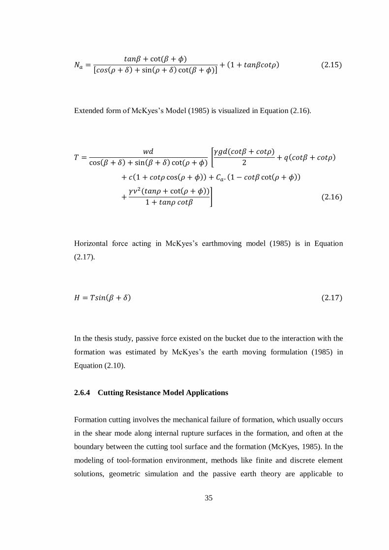
35
( )
[ ( ) ( ) ( )] ( ) ( )
Extended form of McKyes’s Model (1985) is visualized in Equation (2.16).
( ) ( ) ( ) * ( )
( )
( ( )) ( ( ))
( ( ))
+ ( )
Horizontal force acting in McKyes’s earthmoving model (1985) is in Equation
(2.17).
( ) ( )
In the thesis study, passive force existed on the bucket due to the interaction with the
formation was estimated by McKyes’s the earth moving formulation (1985) in
Equation (2.10).
2.6.4 Cutting Resistance Model Applications
Formation cutting involves the mechanical failure of formation, which usually occurs
in the shear mode along internal rupture surfaces in the formation, and often at the
boundary between the cutting tool surface and the formation (McKyes, 1985). In the
modeling of tool-formation environment, methods like finite and discrete element
solutions, geometric simulation and the passive earth theory are applicable to
36
estimate interactions forces (Offei and Frimpong, 2009). In concern with the passive
earth theory, Ericsson (2000) simulated the excavation of wheel loader in software.
The author divided the resistive forces of formation against the bucket as cutting,
penetration, inertial forces and mass flow, and utilized from MyKyes’s method to
calculate approximate counter force in the formation during the cutting operation.
Besides the theoretical models, some laboratory studies have been executed to
optimize the bucket cutting. Maciejewski and Jarzebowski (2002) carried out the
digging process of bucket in a laboratory stand. They basically performed the
operation with a cutting tool into the formation, mounted on the hydraulic cylinders
which measure the horizontal, vertical, and rotational forces during the process. With
theoretical predictions and experimental observations, they modified the parameters
such as shape of cutting tool, digging trajectory, and the angles of tool-formation
interaction angle. Specific energy measurements in the cylinders were taken as
indicator for the effect of parametric changes on overall digging efficiency.
In the thesis study, stress values on the dragline bucket during horizontal cutting
action were investigated. Resistive earth pressure on the digging teeth during the
action was determined using McKyes’s cutting theory (1985). Parameters in the
theory were provided using three different formation data with different
compactness.
2.7 Summary of the Literature Review
A comprehensive literature survey has been carried out to collect information about
previous studies about dragline earthmoving operation and theories behind this
phenomenon. These researches prepared a background for the thesis subject,
investigation of stresses on the dragline bucket with FEA. The literature search
started with the general information about dragline utilization on the world open-cast
mines and dragline stripping methods. Then, it proceeded with the investigation of
productivity factors which effect the efficiency of dragline in the field and review of
the previous studies about dragline productivity.
37
The productivity researches about dragline were surveyed in three main groups, mine
planning and scheduling, operator training, and dragline machinery parts. After
overview of dragline and productivity, literature search advanced in a more specific
field. In this part, it was tried to create a basis for dragline bucket simulation. To
achieve this, components of finite element analysis, principles of earthmoving
operations and factors of formation-tool interaction period were analyzed.
After literature survey, it was observed that there was a lack of enough research
study about stress investigation on an operating dragline bucket. At that point, this
thesis study aims to contribute to the literature, with three dimensional dragline
bucket simulation and stress value investigation on the bucket.
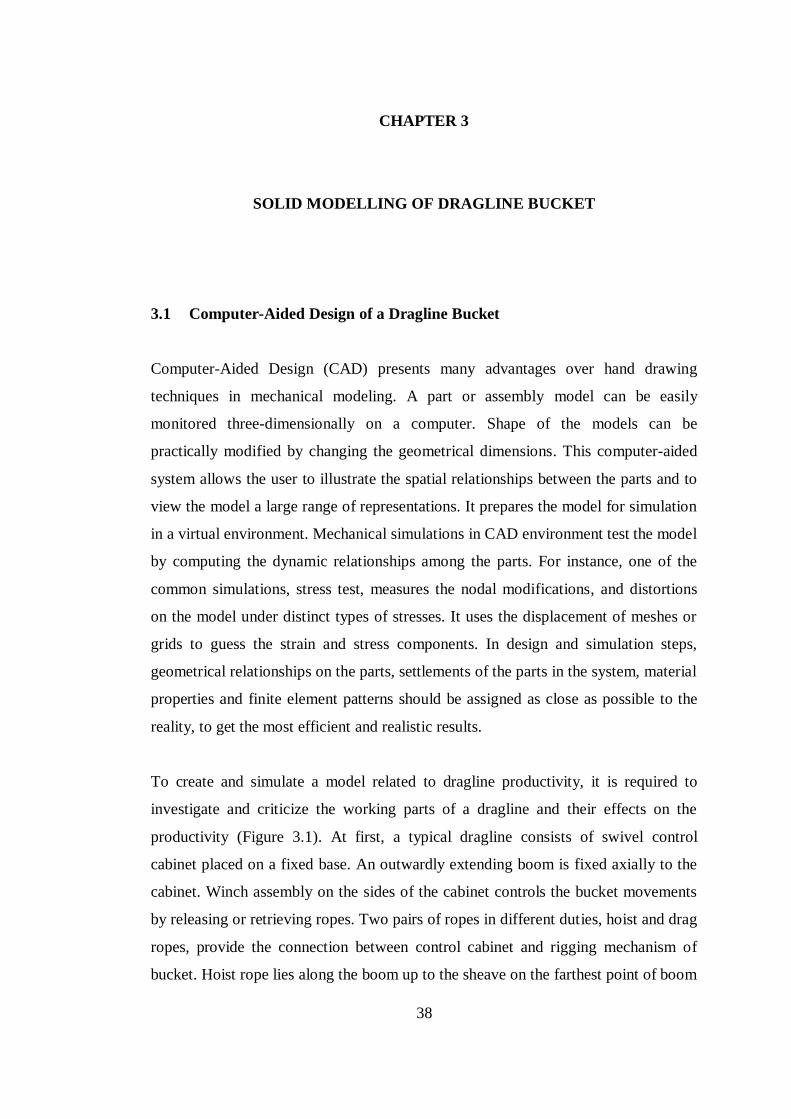
38
CHAPTER 3
3 SOLID MODELLING OF DRAGLINE BUCKET
3.1 Computer-Aided Design of a Dragline Bucket
Computer-Aided Design (CAD) presents many advantages over hand drawing
techniques in mechanical modeling. A part or assembly model can be easily
monitored three-dimensionally on a computer. Shape of the models can be
practically modified by changing the geometrical dimensions. This computer-aided
system allows the user to illustrate the spatial relationships between the parts and to
view the model a large range of representations. It prepares the model for simulation
in a virtual environment. Mechanical simulations in CAD environment test the model
by computing the dynamic relationships among the parts. For instance, one of the
common simulations, stress test, measures the nodal modifications, and distortions
on the model under distinct types of stresses. It uses the displacement of meshes or
grids to guess the strain and stress components. In design and simulation steps,
geometrical relationships on the parts, settlements of the parts in the system, material
properties and finite element patterns should be assigned as close as possible to the
reality, to get the most efficient and realistic results.
To create and simulate a model related to dragline productivity, it is required to
investigate and criticize the working parts of a dragline and their effects on the
productivity (Figure 3.1). At first, a typical dragline consists of swivel control
cabinet placed on a fixed base. An outwardly extending boom is fixed axially to the
cabinet. Winch assembly on the sides of the cabinet controls the bucket movements
by releasing or retrieving ropes. Two pairs of ropes in different duties, hoist and drag
ropes, provide the connection between control cabinet and rigging mechanism of
bucket. Hoist rope lies along the boom up to the sheave on the farthest point of boom
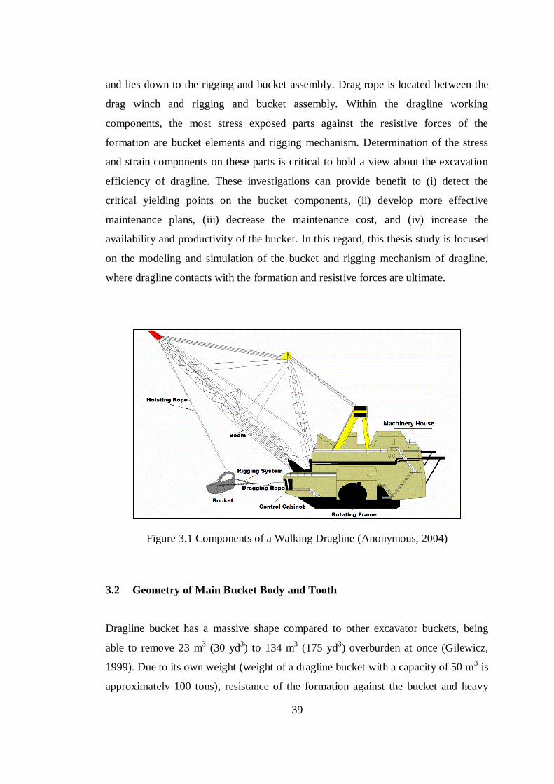
39
and lies down to the rigging and bucket assembly. Drag rope is located between the
drag winch and rigging and bucket assembly. Within the dragline working
components, the most stress exposed parts against the resistive forces of the
formation are bucket elements and rigging mechanism. Determination of the stress
and strain components on these parts is critical to hold a view about the excavation
efficiency of dragline. These investigations can provide benefit to (i) detect the
critical yielding points on the bucket components, (ii) develop more effective
maintenance plans, (iii) decrease the maintenance cost, and (iv) increase the
availability and productivity of the bucket. In this regard, this thesis study is focused
on the modeling and simulation of the bucket and rigging mechanism of dragline,
where dragline contacts with the formation and resistive forces are ultimate.
Figure 3.1 Components of a Walking Dragline (Anonymous, 2004)
3.2 Geometry of Main Bucket Body and Tooth
Dragline bucket has a massive shape compared to other excavator buckets, being
able to remove 23 m3 (30 yd
3) to 134 m
3 (175 yd
3) overburden at once (Gilewicz,
1999). Due to its own weight (weight of a dragline bucket with a capacity of 50 m3 is
approximately 100 tons), resistance of the formation against the bucket and heavy
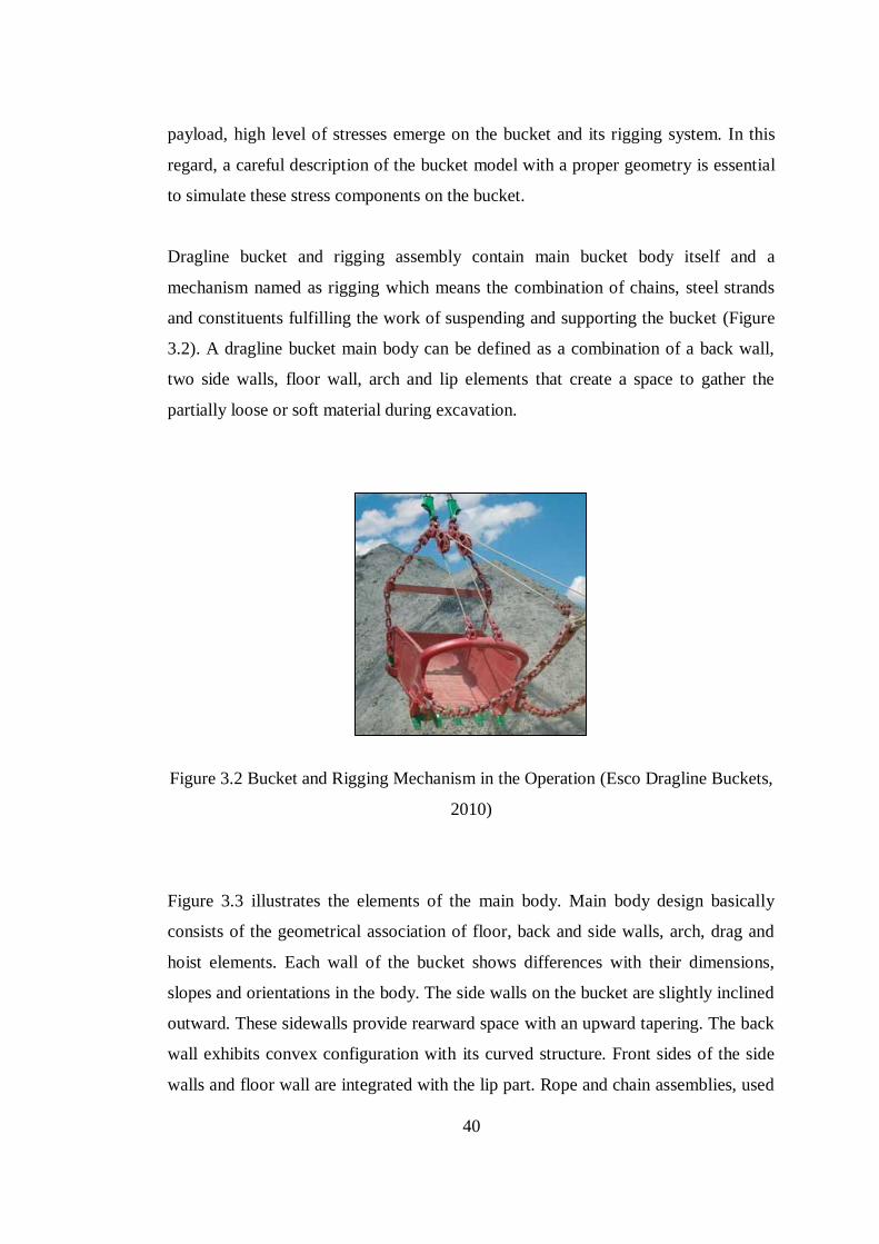
40
payload, high level of stresses emerge on the bucket and its rigging system. In this
regard, a careful description of the bucket model with a proper geometry is essential
to simulate these stress components on the bucket.
Dragline bucket and rigging assembly contain main bucket body itself and a
mechanism named as rigging which means the combination of chains, steel strands
and constituents fulfilling the work of suspending and supporting the bucket (Figure
3.2). A dragline bucket main body can be defined as a combination of a back wall,
two side walls, floor wall, arch and lip elements that create a space to gather the
partially loose or soft material during excavation.
Figure 3.2 Bucket and Rigging Mechanism in the Operation (Esco Dragline Buckets,
2010)
Figure 3.3 illustrates the elements of the main body. Main body design basically
consists of the geometrical association of floor, back and side walls, arch, drag and
hoist elements. Each wall of the bucket shows differences with their dimensions,
slopes and orientations in the body. The side walls on the bucket are slightly inclined
outward. These sidewalls provide rearward space with an upward tapering. The back
wall exhibits convex configuration with its curved structure. Front sides of the side
walls and floor wall are integrated with the lip part. Rope and chain assemblies, used
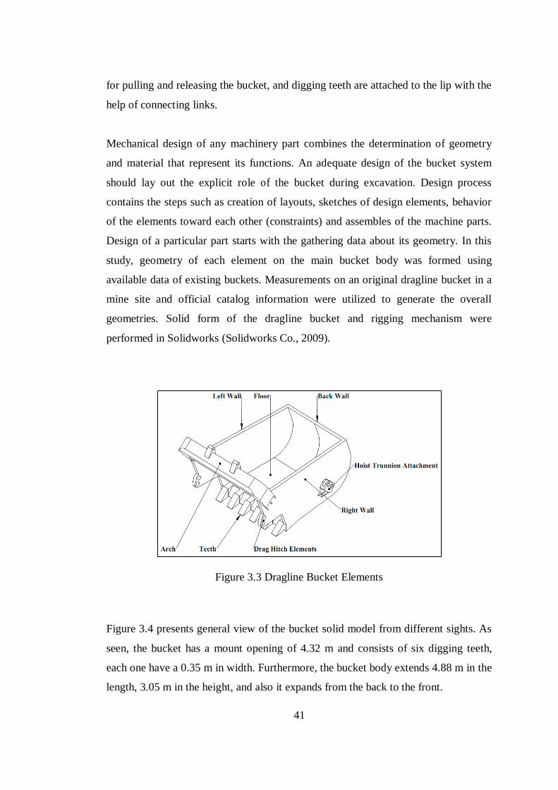
41
for pulling and releasing the bucket, and digging teeth are attached to the lip with the
help of connecting links.
Mechanical design of any machinery part combines the determination of geometry
and material that represent its functions. An adequate design of the bucket system
should lay out the explicit role of the bucket during excavation. Design process
contains the steps such as creation of layouts, sketches of design elements, behavior
of the elements toward each other (constraints) and assembles of the machine parts.
Design of a particular part starts with the gathering data about its geometry. In this
study, geometry of each element on the main bucket body was formed using
available data of existing buckets. Measurements on an original dragline bucket in a
mine site and official catalog information were utilized to generate the overall
geometries. Solid form of the dragline bucket and rigging mechanism were
performed in Solidworks (Solidworks Co., 2009).
Figure 3.3 Dragline Bucket Elements
Figure 3.4 presents general view of the bucket solid model from different sights. As
seen, the bucket has a mount opening of 4.32 m and consists of six digging teeth,
each one have a 0.35 m in width. Furthermore, the bucket body extends 4.88 m in the
length, 3.05 m in the height, and also it expands from the back to the front.
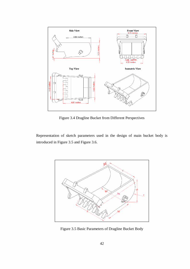
42
Figure 3.4 Dragline Bucket from Different Perspectives
Representation of sketch parameters used in the design of main bucket body is
introduced in Figure 3.5 and Figure 3.6.
Figure 3.5 Basic Parameters of Dragline Bucket Body
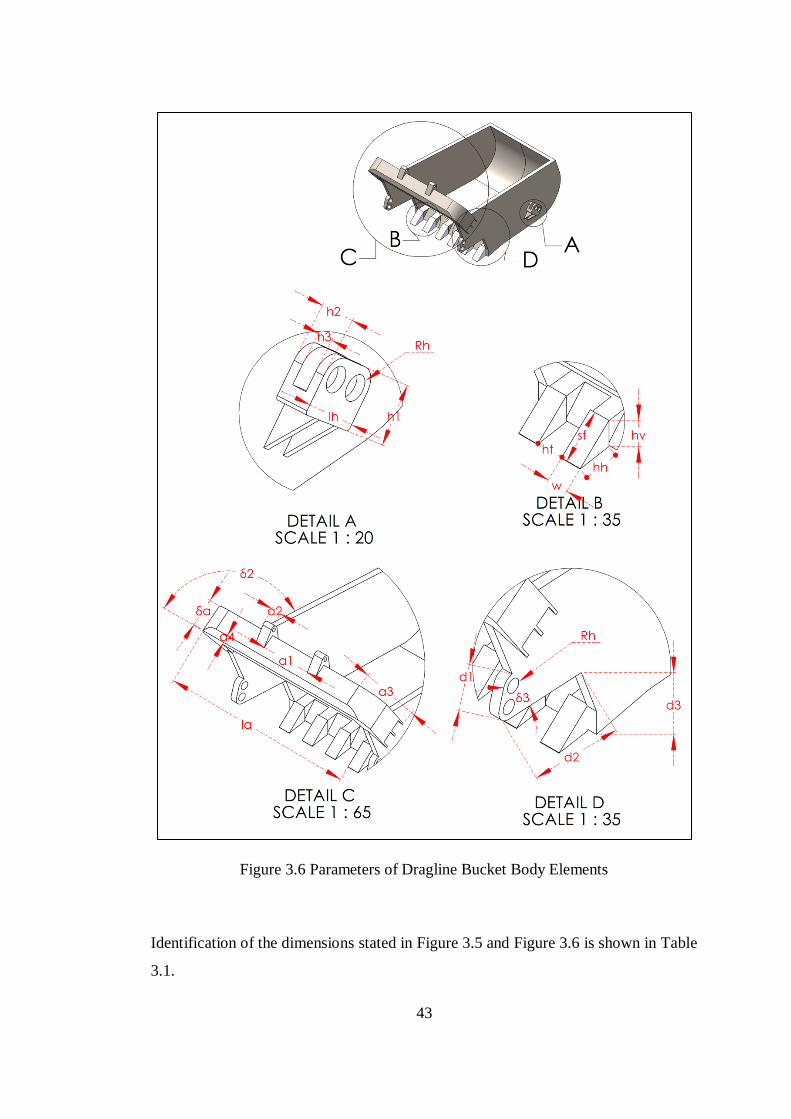
43
Figure 3.6 Parameters of Dragline Bucket Body Elements
Identification of the dimensions stated in Figure 3.5 and Figure 3.6 is shown in Table
3.1.
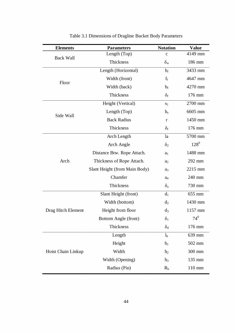
44
Table 3.1 Dimensions of Dragline Bucket Body Parameters
Elements Parameters Notation Value
Back Wall Length (Top)
Thickness
c
δw
4149 mm
186 mm
Floor
Length (Horizontal)
Width (front)
Width (back)
Thickness
hf
ff
bf
δf
3433 mm
4647 mm
4270 mm
176 mm
Side Wall
Height (Vertical)
Length (Top)
Back Radius
Thickness
s1
hs
r
δf
2700 mm
6605 mm
1450 mm
176 mm
Arch
Arch Length
Arch Angle
Distance Btw. Rope Attach.
Thickness of Rope Attach.
Slant Height (from Main Body)
Chamfer
Thickness
la
δ2
a1
a2
a3
a4
δa
5700 mm
1280
1488 mm
292 mm
2215 mm
240 mm
730 mm
Drag Hitch Element
Slant Height (front)
Width (bottom)
Height from floor
Bottom Angle (front)
Thickness
d1
d2
d3
δ1
δd
655 mm
1430 mm
1157 mm
740
176 mm
Hoist Chain Linkup
Length
Height
Width
Width (Opening)
Radius (Pin)
lh
h1
h2
h3
Rh
639 mm
502 mm
300 mm
135 mm
110 mm
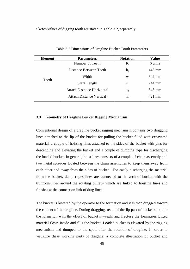
45
Sketch values of digging tooth are stated in Table 3.2, separately.
Table 3.2 Dimensions of Dragline Bucket Tooth Parameters
Element Parameters Notation Value
Teeth
Number of Teeth
Distance Between Teeth
Width
Slant Length
Attach Distance Horizontal
Attach Distance Vertical
K
ht
w
sf
hh
hv
6 units
445 mm
349 mm
744 mm
545 mm
421 mm
3.3 Geometry of Dragline Bucket Rigging Mechanism
Conventional design of a dragline bucket rigging mechanism contains two dragging
lines attached to the lip of the bucket for pulling the bucket filled with excavated
material, a couple of hoisting lines attached to the sides of the bucket with pins for
descending and elevating the bucket and a couple of dumping rope for discharging
the loaded bucket. In general, hoist lines consists of a couple of chain assembly and
two metal spreader located between the chain assemblies to keep them away from
each other and away from the sides of bucket. For easily discharging the material
from the bucket, dump ropes lines are connected to the arch of bucket with the
trunnions, lies around the rotating pulleys which are linked to hoisting lines and
finishes at the connection link of drag lines.
The bucket is lowered by the operator to the formation and it is then dragged toward
the cabinet of the dragline. During dragging, teeth of the lip part of bucket sink into
the formation with the effect of bucket’s weight and fracture the formation. Lifted
material flows inside and fills the bucket. Loaded bucket is elevated by the rigging
mechanism and dumped to the spoil after the rotation of dragline. In order to
visualize these working parts of dragline, a complete illustration of bucket and
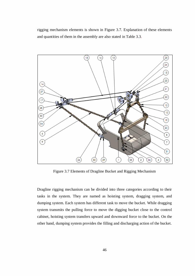
46
rigging mechanism elements is shown in Figure 3.7. Explanation of these elements
and quantities of them in the assembly are also stated in Table 3.3.
Figure 3.7 Elements of Dragline Bucket and Rigging Mechanism
Dragline rigging mechanism can be divided into three categories according to their
tasks in the system. They are named as hoisting system, dragging system, and
dumping system. Each system has different task to move the bucket. While dragging
system transmits the pulling force to move the digging bucket close to the control
cabinet, hoisting system transfers upward and downward force to the bucket. On the
other hand, dumping system provides the filling and discharging action of the bucket.
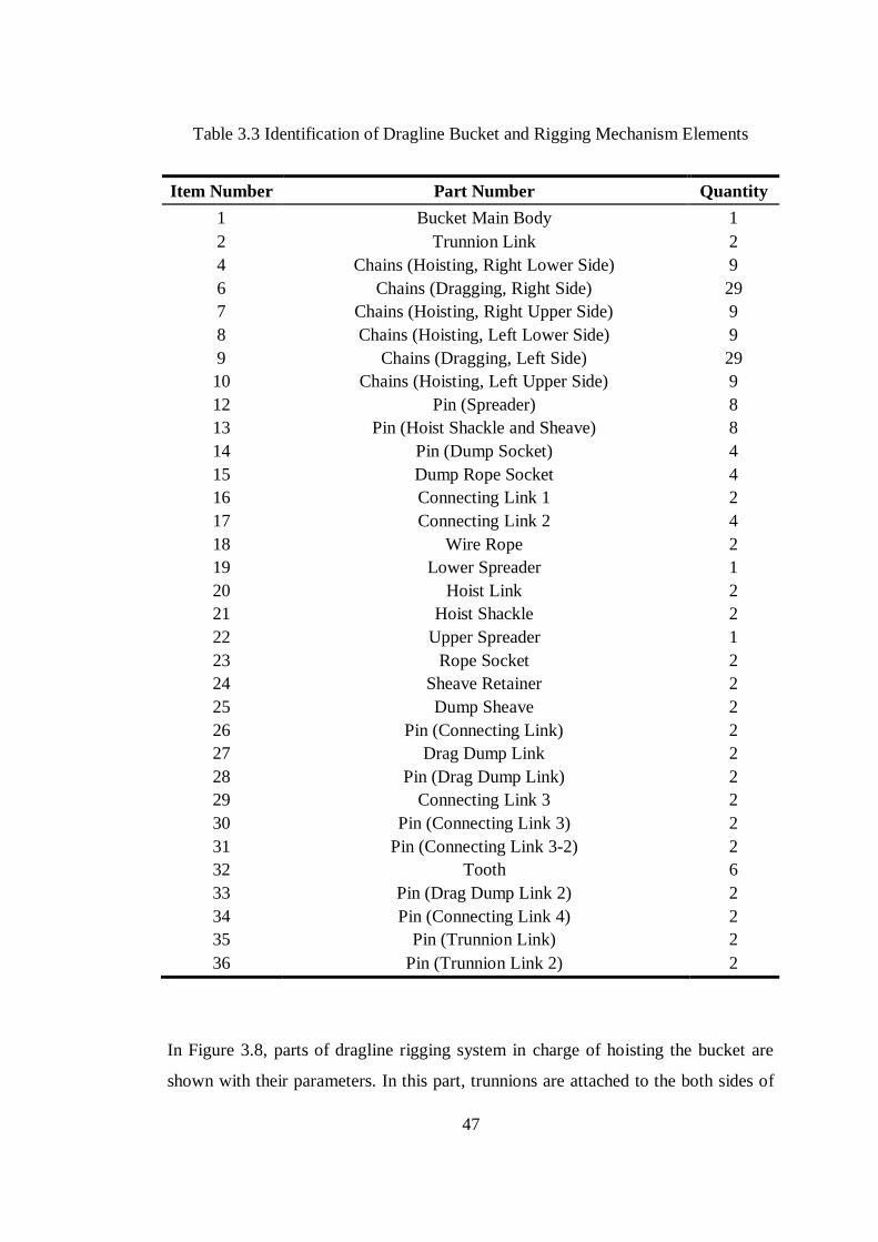
47
Table 3.3 Identification of Dragline Bucket and Rigging Mechanism Elements
Item Number Part Number Quantity
1 Bucket Main Body 1
2 Trunnion Link 2
4 Chains (Hoisting, Right Lower Side) 9
6 Chains (Dragging, Right Side) 29
7 Chains (Hoisting, Right Upper Side) 9
8 Chains (Hoisting, Left Lower Side) 9
9 Chains (Dragging, Left Side) 29
10 Chains (Hoisting, Left Upper Side) 9
12 Pin (Spreader) 8
13 Pin (Hoist Shackle and Sheave) 8
14 Pin (Dump Socket) 4
15 Dump Rope Socket 4
16 Connecting Link 1 2
17 Connecting Link 2 4
18 Wire Rope 2
19 Lower Spreader 1
20 Hoist Link 2
21 Hoist Shackle 2
22 Upper Spreader 1
23 Rope Socket 2
24 Sheave Retainer 2
25 Dump Sheave 2
26 Pin (Connecting Link) 2
27 Drag Dump Link 2
28 Pin (Drag Dump Link) 2
29 Connecting Link 3 2
30 Pin (Connecting Link 3) 2
31 Pin (Connecting Link 3-2) 2
32 Tooth 6
33 Pin (Drag Dump Link 2) 2
34 Pin (Connecting Link 4) 2
35 Pin (Trunnion Link) 2
36 Pin (Trunnion Link 2) 2
In Figure 3.8, parts of dragline rigging system in charge of hoisting the bucket are
shown with their parameters. In this part, trunnions are attached to the both sides of
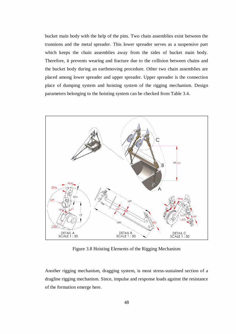
48
bucket main body with the help of the pins. Two chain assemblies exist between the
trunnions and the metal spreader. This lower spreader serves as a suspensive part
which keeps the chain assemblies away from the sides of bucket main body.
Therefore, it prevents wearing and fracture due to the collision between chains and
the bucket body during an earthmoving procedure. Other two chain assemblies are
placed among lower spreader and upper spreader. Upper spreader is the connection
place of dumping system and hoisting system of the rigging mechanism. Design
parameters belonging to the hoisting system can be checked from Table 3.4.
Figure 3.8 Hoisting Elements of the Rigging Mechanism
Another rigging mechanism, dragging system, is most stress-sustained section of a
dragline rigging mechanism. Since, impulse and response loads against the resistance
of the formation emerge here.
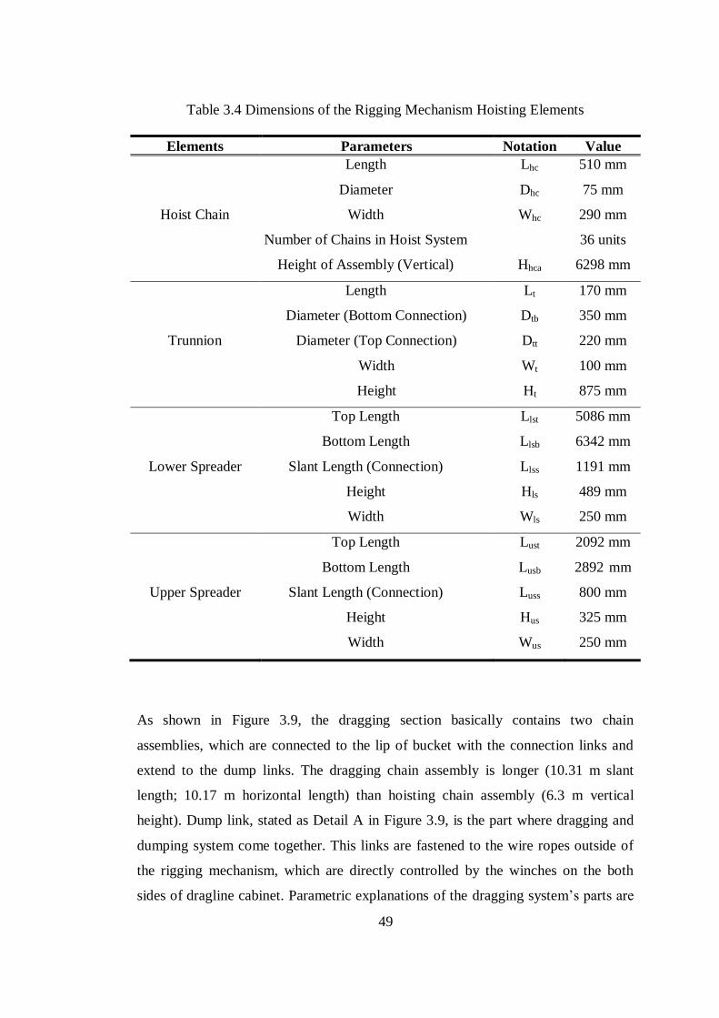
49
Table 3.4 Dimensions of the Rigging Mechanism Hoisting Elements
Elements Parameters Notation Value
Hoist Chain
Length
Diameter
Width
Number of Chains in Hoist System
Height of Assembly (Vertical)
Lhc
Dhc
Whc
Hhca
510 mm
75 mm
290 mm
36 units
6298 mm
Trunnion
Length
Diameter (Bottom Connection)
Diameter (Top Connection)
Width
Height
Lt
Dtb
Dtt
Wt
Ht
170 mm
350 mm
220 mm
100 mm
875 mm
Lower Spreader
Top Length
Bottom Length
Slant Length (Connection)
Height
Width
Llst
Llsb
Llss
Hls
Wls
5086 mm
6342 mm
1191 mm
489 mm
250 mm
Upper Spreader
Top Length
Bottom Length
Slant Length (Connection)
Height
Width
Lust
Lusb
Luss
Hus
Wus
2092 mm
2892 mm
800 mm
325 mm
250 mm
As shown in Figure 3.9, the dragging section basically contains two chain
assemblies, which are connected to the lip of bucket with the connection links and
extend to the dump links. The dragging chain assembly is longer (10.31 m slant
length; 10.17 m horizontal length) than hoisting chain assembly (6.3 m vertical
height). Dump link, stated as Detail A in Figure 3.9, is the part where dragging and
dumping system come together. This links are fastened to the wire ropes outside of
the rigging mechanism, which are directly controlled by the winches on the both
sides of dragline cabinet. Parametric explanations of the dragging system’s parts are
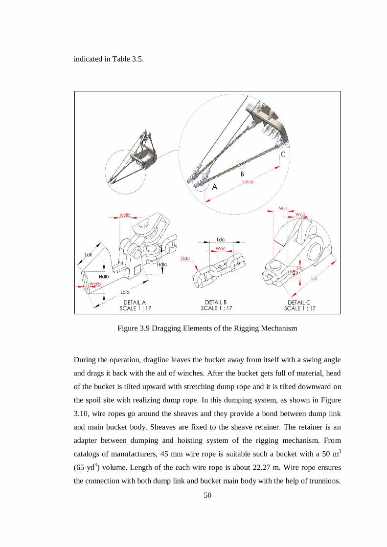
50
indicated in Table 3.5.
Figure 3.9 Dragging Elements of the Rigging Mechanism
During the operation, dragline leaves the bucket away from itself with a swing angle
and drags it back with the aid of winches. After the bucket gets full of material, head
of the bucket is tilted upward with stretching dump rope and it is tilted downward on
the spoil site with realizing dump rope. In this dumping system, as shown in Figure
3.10, wire ropes go around the sheaves and they provide a bond between dump link
and main bucket body. Sheaves are fixed to the sheave retainer. The retainer is an
adapter between dumping and hoisting system of the rigging mechanism. From
catalogs of manufacturers, 45 mm wire rope is suitable such a bucket with a 50 m3
(65 yd3) volume. Length of the each wire rope is about 22.27 m. Wire rope ensures
the connection with both dump link and bucket main body with the help of trunnions.
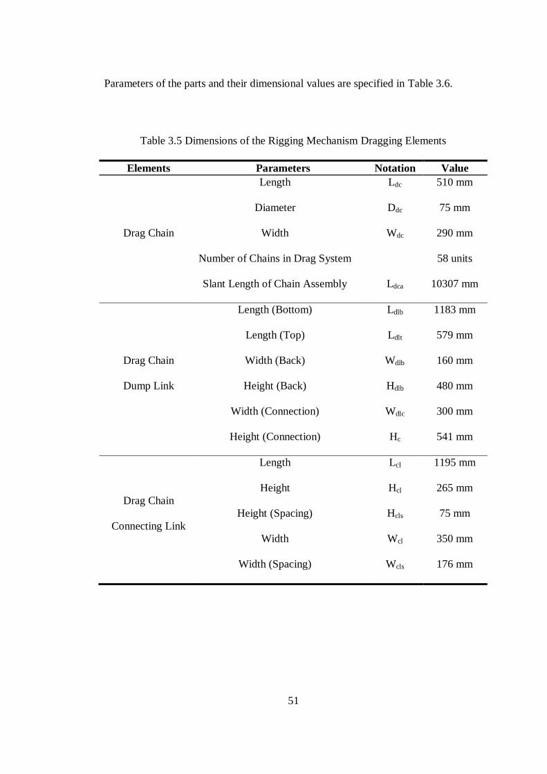
51
Parameters of the parts and their dimensional values are specified in Table 3.6.
Table 3.5 Dimensions of the Rigging Mechanism Dragging Elements
Elements Parameters Notation Value
Drag Chain
Length
Diameter
Width
Number of Chains in Drag System
Slant Length of Chain Assembly
Ldc
Ddc
Wdc
Ldca
510 mm
75 mm
290 mm
58 units
10307 mm
Drag Chain
Dump Link
Length (Bottom)
Length (Top)
Width (Back)
Height (Back)
Width (Connection)
Height (Connection)
Ldlb
Ldlt
Wdlb
Hdlb
Wdlc
Hc
1183 mm
579 mm
160 mm
480 mm
300 mm
541 mm
Drag Chain
Connecting Link
Length
Height
Height (Spacing)
Width
Width (Spacing)
Lcl
Hcl
Hcls
Wcl
Wcls
1195 mm
265 mm
75 mm
350 mm
176 mm
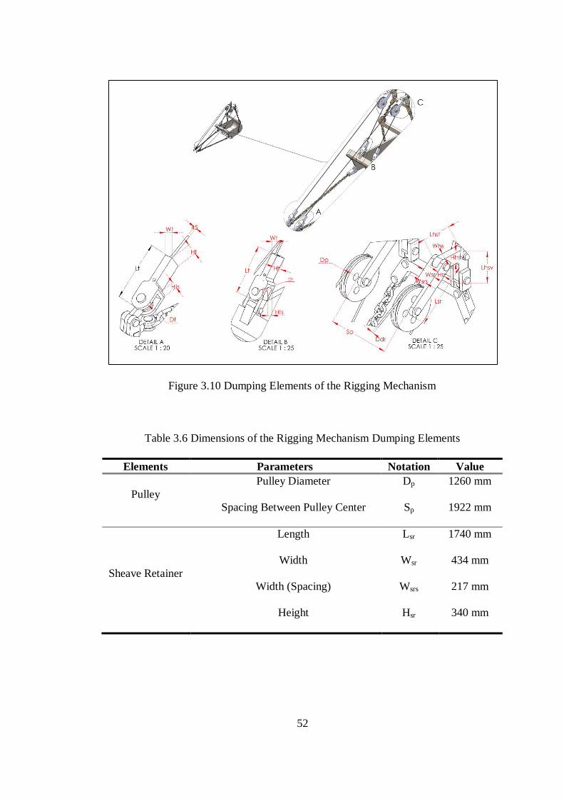
52
Figure 3.10 Dumping Elements of the Rigging Mechanism
Table 3.6 Dimensions of the Rigging Mechanism Dumping Elements
Elements Parameters Notation Value
Pulley
Pulley Diameter
Spacing Between Pulley Center
Dp
Sp
1260 mm
1922 mm
Sheave Retainer
Length
Width
Width (Spacing)
Height
Lsr
Wsr
Wsrs
Hsr
1740 mm
434 mm
217 mm
340 mm
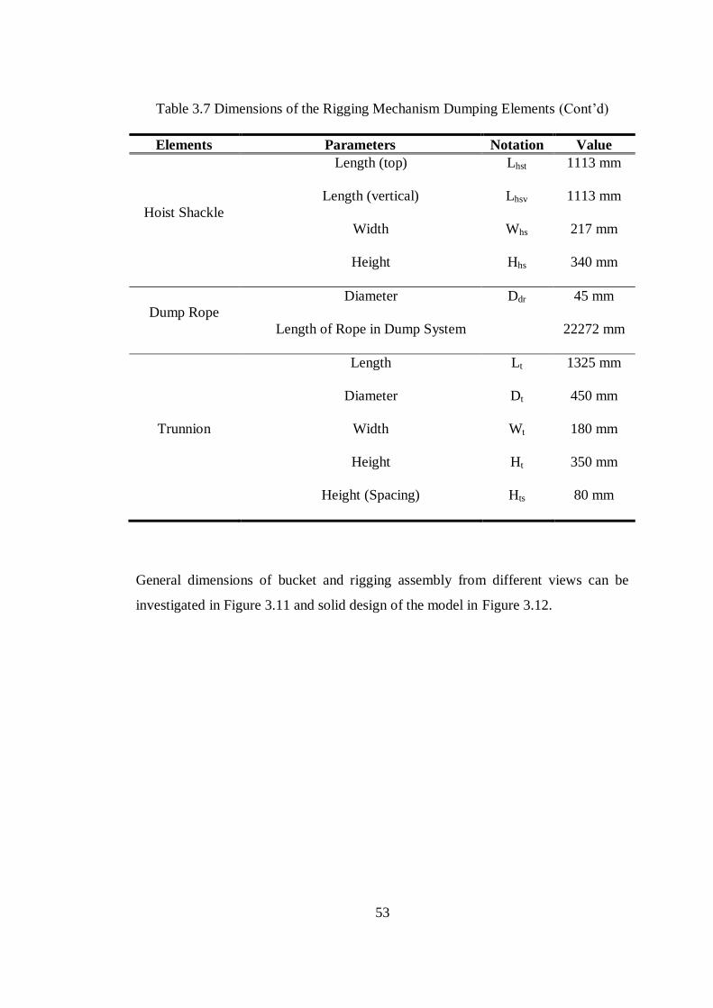
53
Table 3.7 Dimensions of the Rigging Mechanism Dumping Elements (Cont’d)
Elements Parameters Notation Value
Hoist Shackle
Length (top)
Length (vertical)
Width
Height
Lhst
Lhsv
Whs
Hhs
1113 mm
1113 mm
217 mm
340 mm
Dump Rope
Diameter
Length of Rope in Dump System
Ddr
45 mm
22272 mm
Trunnion
Length
Diameter
Width
Height
Height (Spacing)
Lt
Dt
Wt
Ht
Hts
1325 mm
450 mm
180 mm
350 mm
80 mm
General dimensions of bucket and rigging assembly from different views can be
investigated in Figure 3.11 and solid design of the model in Figure 3.12.
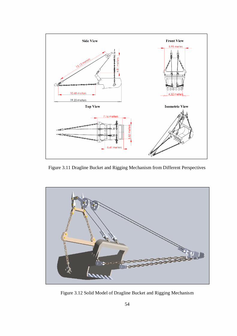
54
Figure 3.11 Dragline Bucket and Rigging Mechanism from Different Perspectives
Figure 3.12 Solid Model of Dragline Bucket and Rigging Mechanism
55
CHAPTER 4
4 DIGGING SIMULATION OF WALKING DRAGLINE BUCKET
4.1 Resistive Force Calculations
4.1.1 Formation Specifications
In order to effectively estimate a bucket action into the formation, it is essential to
find the resistive forces of the formation against the bucket. In this regard, it is
required to know the principles behind the contradictory response of the formation,
to calculate these earthmoving forces. A dragline bucket constitutively performs the
earthmoving process with penetration and cutting actions. It initially penetrates the
formation and cuts it until filling its volume with loose material. Since, bucket
penetration mechanism shows similar principles with bucket cutting mechanism,
cutting theory was utilized to calculate the resistive force in the thesis study.
As discussed in Chapter 3, different types of analytical and theoretical approaches
are available for the cutting force estimation. These models contain parameters
related to formation specifications and tool-formation interaction properties. In the
thesis research, formation data were directly taken from the study performed by
Mouazen and Nemenyi (1999) with the authors’ permissions. Table 4.1 illustrates the
specifications belonging to three different conditions of the same formation, very
compacted, compacted and loose. These formation specimens have homogeneous
particle distributions and different mechanical specifications.
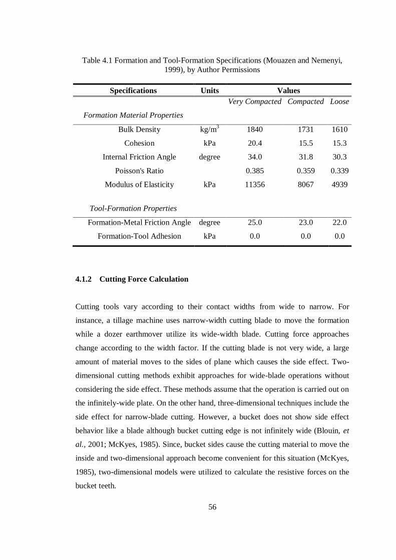
56
Table 4.1 Formation and Tool-Formation Specifications (Mouazen and Nemenyi,
1999), by Author Permissions
Specifications Units Values
Very Compacted Compacted Loose
Formation Material Properties
Bulk Density kg/m3 1840 1731 1610
Cohesion kPa 20.4 15.5 15.3
Internal Friction Angle degree 34.0 31.8 30.3
Poisson's Ratio
0.385 0.359 0.339
Modulus of Elasticity kPa 11356 8067 4939
Tool-Formation Properties
Formation-Metal Friction Angle degree 25.0 23.0 22.0
Formation-Tool Adhesion kPa 0.0 0.0 0.0
4.1.2 Cutting Force Calculation
Cutting tools vary according to their contact widths from wide to narrow. For
instance, a tillage machine uses narrow-width cutting blade to move the formation
while a dozer earthmover utilize its wide-width blade. Cutting force approaches
change according to the width factor. If the cutting blade is not very wide, a large
amount of material moves to the sides of plane which causes the side effect. Two-
dimensional cutting methods exhibit approaches for wide-blade operations without
considering the side effect. These methods assume that the operation is carried out on
the infinitely-wide plate. On the other hand, three-dimensional techniques include the
side effect for narrow-blade cutting. However, a bucket does not show side effect
behavior like a blade although bucket cutting edge is not infinitely wide (Blouin, et
al., 2001; McKyes, 1985). Since, bucket sides cause the cutting material to move the
inside and two-dimensional approach become convenient for this situation (McKyes,
1985), two-dimensional models were utilized to calculate the resistive forces on the
bucket teeth.
57
As indicated in the Equation (2.10), total resistive force on the teeth can be estimated
from the forces related to the weight of removing formation, cohesion between
formation-formation interaction, adhesion between tool-formation interaction,
surface surcharge pressure and inertia inside the formation (Figure 4.1). In this thesis
study, resistive forces such as adhesion, surcharge, and inertia forces were neglected
in the calculation of total resistive force. On the formation failure surface, there is a
potential perpendicular pressure, q, due to a loose surcharge rising there. This extra
pressure can occur because of any probable loading on the surface, whether from a
machine or the existence of a loose material whose weight must be supported by the
surface. In the study, this type of force was neglected. Moreover, adhesion force can
be described as the force of attraction between different materials. In the study,
formation and the bucket teeth are two distinct materials and interaction between
them was assumed zero. In addition, effect of inertia is released when formation is
accelerated from resting state to a specific velocity (Abo-Elnor et al., 2004). Since
constant velocity bucket movement was applied in the study, inertial force was also
neglected.
Weight of removing formation body can be assumed to contribute a
negligible resistance on the total resistance when the cutting operation is achieved in
the shallow depths (McKyes, 1985). However, in the study, bucket operates in a 512
mm depth (Figure 4.2). It evokes a remarkable load on the teeth. Therefore, weight
of the formation body was included to the earth passive pressure formula.
Furthermore, cohesion is one of the fundamental factor which headlight the
interaction between formation-formation. It can be defined as a force due to
attraction between the formation particles. If there is not cohesion, no fragmentation
observes in the formation and particles behave independently of each other. Thus,
cohesion force was taken into account of resistive force calculation. Therefore,
weight and cohesion were taken as two factors utilized in the determination of
formation resistive forces in the study.
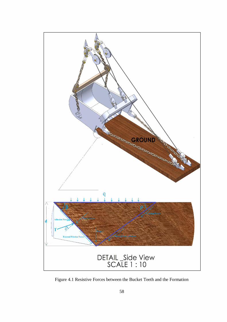
58
Figure 4.1 Resistive Forces between the Bucket Teeth and the Formation
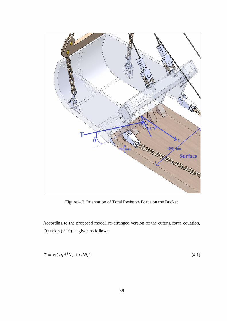
59
Figure 4.2 Orientation of Total Resistive Force on the Bucket
According to the proposed model, re-arranged version of the cutting force equation,
Equation (2.10), is given as follows:
( ) (4.1)
60
In Equation (4.1):
= Cutting Width (m)
= Formation Density ( ⁄ )
= Gravitational Acceleration ( ⁄ )
= Depth of Work (m)
= Formation Cohesion Strength (kPa)
= Weight Factor
= Cohesion Factor
As mentioned in Chapter 4.1.1, formation specifications stated in Equation (4.1)
were taken from the study of Mouazen and Nemenyi (1999) by authors’ permissions.
In addition to these data, Nc and Nγ factors were provided from the charts generated
by Hettiaratchi and Reece (1974). Mckyes (1985) states that Hettiaratchi’s charts for
N-factors can be used efficiently for the rapid solution of passive earth pressure
formulas. Charts only give N-factors for the situations of δ=0 and δ=. Therefore, to
find N-factors for a specific δ value, Equation (4.2) is used as stated below. This
equation provides a linear relationship between N-factors and external friction angle.
( )
(4.2)
In Equation (4.2):
= External Friction Angle
= Internal Friction Angle
= N Factor for a Specific External Friction Angle
= N Factor where External Friction Angle is zero
= N Factor where External Friction Angle is Equal to Internal Friction
Angle
61
Calculation of the resistive force for very compacted formation type which is stated
in Table 4.1, is explained below.
Predetermined data to use in Equation (4.1) are indicated in Table 4.1 and Figure 4.2,
except for Nγ and Nc. Weight factor, Nγ, and cohesion factor, Nc, are determined
from the charts as follows:
Calculation of Nγ:
From Figure A.1 (see Appendix A), for external friction angle (δ) is 00, internal
friction angle () is 34.00, and rake angle of the cutting teeth ( ) is 43.78
0:
is calculated as 0.99.
From Figure A.2 (see Appendix A), for external friction angle (δ) is equal to internal
friction angle, internal friction angle () is 34.00, and rake angle of the cutting teeth
( ) is 43.780:
is calculated as 2.00.
From Equation (4.2); for δ=250,
( )
Calculation of Nc:
From Figure A.3 (see Appendix A), for external friction angle (δ) is 00, internal
friction angle () is 34.00, and rake angle of the cutting teeth ( ) is 43.78
0:
is calculated as 0.85.
From Figure A.4 (see Appendix A), for external friction angle (δ) is equal to internal
friction angle, internal friction angle () is 34.00, and rake angle of the cutting teeth
( ) is 43.780:
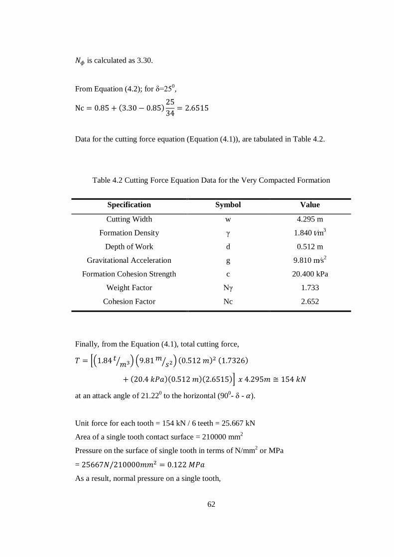
62
is calculated as 3.30.
From Equation (4.2); for δ=250,
( )
Data for the cutting force equation (Equation (4.1)), are tabulated in Table 4.2.
Table 4.2 Cutting Force Equation Data for the Very Compacted Formation
Specification Symbol Value
Cutting Width w 4.295 m
Formation Density γ 1.840 t⁄m3
Depth of Work d 0.512 m
Gravitational Acceleration g 9.810 m⁄s2
Formation Cohesion Strength c 20.400 kPa
Weight Factor Nγ 1.733
Cohesion Factor Nc 2.652
Finally, from the Equation (4.1), total cutting force,
*( ⁄ ) ( ⁄ ) ( ) ( )
( )( )( )+
at an attack angle of 21.220 to the horizontal (90
0- δ - ).
Unit force for each tooth = 154 kN / 6 teeth = 25.667 kN
Area of a single tooth contact surface = 210000 mm2
Pressure on the surface of single tooth in terms of N/mm2 or MPa
=
As a result, normal pressure on a single tooth,
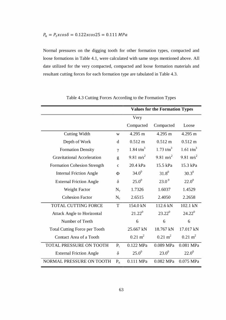
63
Normal pressures on the digging tooth for other formation types, compacted and
loose formations in Table 4.1, were calculated with same steps mentioned above. All
date utilized for the very compacted, compacted and loose formation materials and
resultant cutting forces for each formation type are tabulated in Table 4.3.
Table 4.3 Cutting Forces According to the Formation Types
Values for the Formation Types
Very
Compacted Compacted Loose
Cutting Width w 4.295 m 4.295 m 4.295 m
Depth of Work d 0.512 m 0.512 m 0.512 m
Formation Density γ 1.84 t⁄m3 1.73 t⁄m
3 1.61 t⁄m
3
Gravitational Acceleration g 9.81 m⁄s2 9.81 m⁄s
2 9.81 m⁄s
2
Formation Cohesion Strength c 20.4 kPa 15.5 kPa 15.3 kPa
Internal Friction Angle 34.00
31.80
30.30
External Friction Angle δ 25.00
23.0 0
22.00
Weight Factor Nγ 1.7326 1.6037 1.4529
Cohesion Factor Nc 2.6515 2.4050 2.2658
TOTAL CUTTING FORCE T 154.0 kN
112.6 kN 102.1 kN
Attack Angle to Horizontal 21.220 23.22
0 24.22
0
Number of Teeth 6 6 6
Total Cutting Force per Tooth 25.667 kN 18.767 kN 17.017 kN
Contact Area of a Tooth 0.21 m2
0.21 m2 0.21 m
2
TOTAL PRESSURE ON TOOTH Pt 0.122 MPa 0.089 MPa 0.081 MPa
External Friction Angle δ 25.00
23.00
22.00
NORMAL PRESSURE ON TOOTH Pn 0.111 MPa 0.082 MPa 0.075 MPa
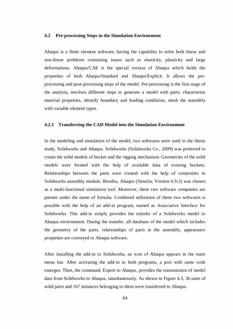
64
4.2 Pre-processing Steps in the Simulation Environment
Abaqus is a finite element software, having the capability to solve both linear and
non-linear problems containing issues such as elasticity, plasticity and large
deformations. Abaqus/CAE is the special version of Abaqus which holds the
properties of both Abaqus/Standard and Abaqus/Explicit. It allows the pre-
processing and post-processing steps of the model. Pre-processing is the first stage of
the analysis, involves different steps to generate a model with parts, characterize
material properties, identify boundary and loading conditions, mesh the assembly
with variable element types.
4.2.1 Transferring the CAD Model into the Simulation Environment
In the modeling and simulation of the model, two softwares were used in the thesis
study, Solidworks and Abaqus. Solidworks (Solidworks Co., 2009) was preferred to
create the solid models of bucket and the rigging mechanism. Geometries of the solid
models were formed with the help of available data of existing buckets.
Relationships between the parts were created with the help of constraints in
Solidworks assembly module. Besides, Abaqus (Simulia, Version 6.9-2) was chosen
as a multi-functional simulation tool. Moreover, these two software companies are
partner under the name of Simulia. Combined utilization of these two softwares is
possible with the help of an add-in program, named as Associative Interface for
Solidworks. This add-in simply provides the transfer of a Solidworks model to
Abaqus environment. During the transfer, all database of the model which includes
the geometry of the parts, relationships of parts in the assembly, appearance
properties are conveyed to Abaqus software.
After installing the add-in to Solidworks, an icon of Abaqus appears in the main
menu bar. After activating the add-in in both programs, a port with same code
emerges. Then, the command, Export to Abaqus, provides the transmission of model
data from Solidworks to Abaqus, simultaneously. As shown in Figure 4.3, 36 units of
solid parts and 167 instances belonging to them were transferred to Abaqus.
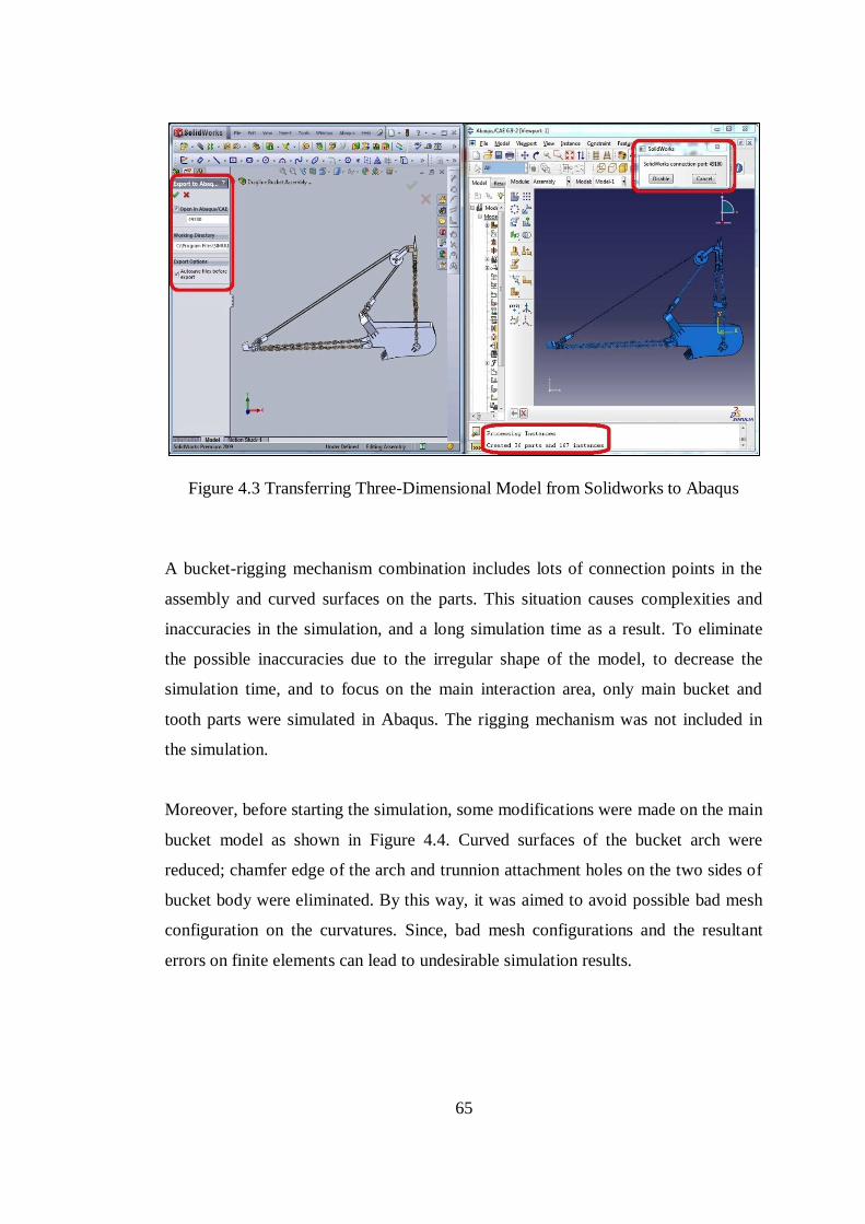
65
Figure 4.3 Transferring Three-Dimensional Model from Solidworks to Abaqus
A bucket-rigging mechanism combination includes lots of connection points in the
assembly and curved surfaces on the parts. This situation causes complexities and
inaccuracies in the simulation, and a long simulation time as a result. To eliminate
the possible inaccuracies due to the irregular shape of the model, to decrease the
simulation time, and to focus on the main interaction area, only main bucket and
tooth parts were simulated in Abaqus. The rigging mechanism was not included in
the simulation.
Moreover, before starting the simulation, some modifications were made on the main
bucket model as shown in Figure 4.4. Curved surfaces of the bucket arch were
reduced; chamfer edge of the arch and trunnion attachment holes on the two sides of
bucket body were eliminated. By this way, it was aimed to avoid possible bad mesh
configuration on the curvatures. Since, bad mesh configurations and the resultant
errors on finite elements can lead to undesirable simulation results.
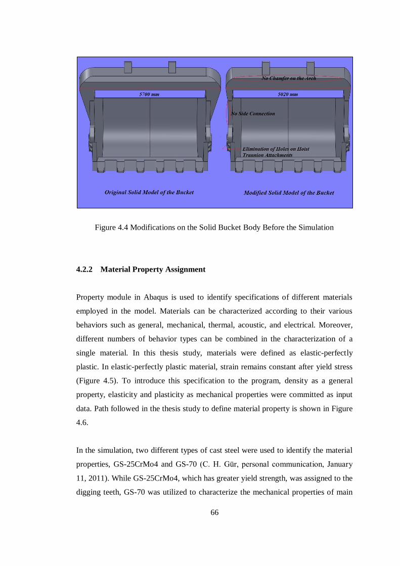
66
Figure 4.4 Modifications on the Solid Bucket Body Before the Simulation
4.2.2 Material Property Assignment
Property module in Abaqus is used to identify specifications of different materials
employed in the model. Materials can be characterized according to their various
behaviors such as general, mechanical, thermal, acoustic, and electrical. Moreover,
different numbers of behavior types can be combined in the characterization of a
single material. In this thesis study, materials were defined as elastic-perfectly
plastic. In elastic-perfectly plastic material, strain remains constant after yield stress
(Figure 4.5). To introduce this specification to the program, density as a general
property, elasticity and plasticity as mechanical properties were committed as input
data. Path followed in the thesis study to define material property is shown in Figure
4.6.
In the simulation, two different types of cast steel were used to identify the material
properties, GS-25CrMo4 and GS-70 (C. H. Gür, personal communication, January
11, 2011). While GS-25CrMo4, which has greater yield strength, was assigned to the
digging teeth, GS-70 was utilized to characterize the mechanical properties of main
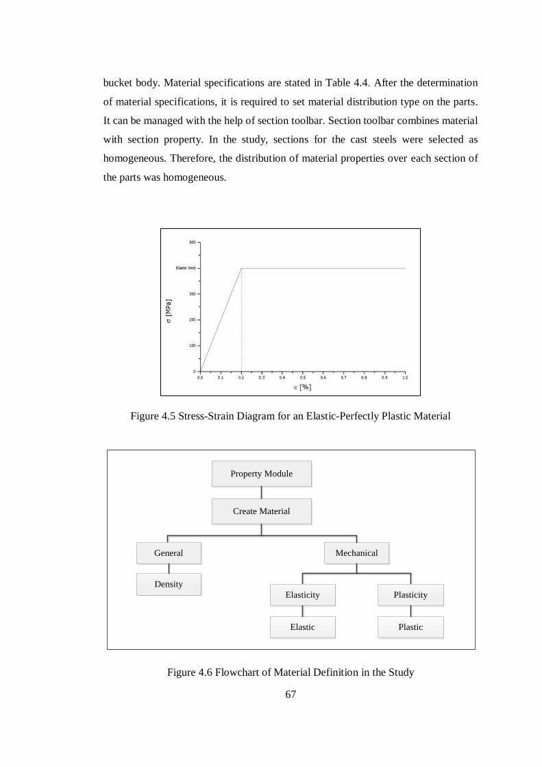
67
bucket body. Material specifications are stated in Table 4.4. After the determination
of material specifications, it is required to set material distribution type on the parts.
It can be managed with the help of section toolbar. Section toolbar combines material
with section property. In the study, sections for the cast steels were selected as
homogeneous. Therefore, the distribution of material properties over each section of
the parts was homogeneous.
Figure 4.5 Stress-Strain Diagram for an Elastic-Perfectly Plastic Material
Create Material
General Mechanical
Density
Property Module
Elasticity Plasticity
Elastic Plastic
Figure 4.6 Flowchart of Material Definition in the Study
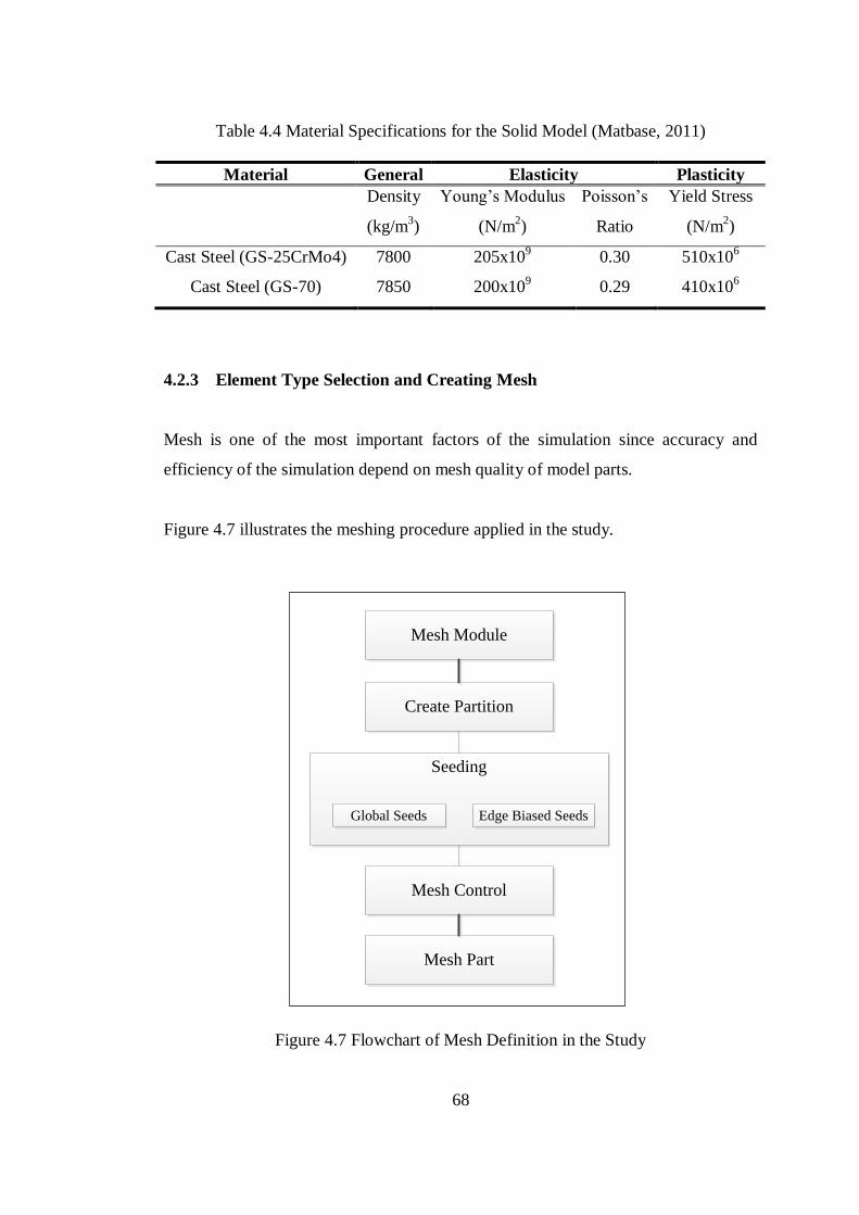
68
Table 4.4 Material Specifications for the Solid Model (Matbase, 2011)
Material General Elasticity Plasticity
Density
(kg/m3)
Young’s Modulus
(N/m2)
Poisson’s
Ratio
Yield Stress
(N/m2)
Cast Steel (GS-25CrMo4) 7800 205x109 0.30 510x10
6
Cast Steel (GS-70) 7850 200x109 0.29 410x10
6
4.2.3 Element Type Selection and Creating Mesh
Mesh is one of the most important factors of the simulation since accuracy and
efficiency of the simulation depend on mesh quality of model parts.
Figure 4.7 illustrates the meshing procedure applied in the study.
Create Partition
Mesh Module
Mesh Control
Mesh Part
Seeding
Global Seeds Edge Biased Seeds
Figure 4.7 Flowchart of Mesh Definition in the Study
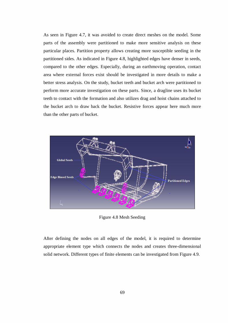
69
As seen in Figure 4.7, it was avoided to create direct meshes on the model. Some
parts of the assembly were partitioned to make more sensitive analysis on these
particular places. Partition property allows creating more susceptible seeding in the
partitioned sides. As indicated in Figure 4.8, highlighted edges have denser in seeds,
compared to the other edges. Especially, during an earthmoving operation, contact
area where external forces exist should be investigated in more details to make a
better stress analysis. On the study, bucket teeth and bucket arch were partitioned to
perform more accurate investigation on these parts. Since, a dragline uses its bucket
teeth to contact with the formation and also utilizes drag and hoist chains attached to
the bucket arch to draw back the bucket. Resistive forces appear here much more
than the other parts of bucket.
Figure 4.8 Mesh Seeding
After defining the nodes on all edges of the model, it is required to determine
appropriate element type which connects the nodes and creates three-dimensional
solid network. Different types of finite elements can be investigated from Figure 4.9.
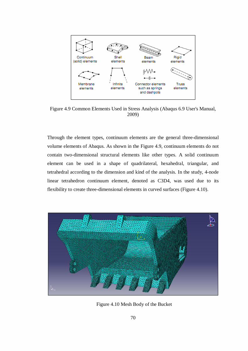
70
Figure 4.9 Common Elements Used in Stress Analysis (Abaqus 6.9 User's Manual,
2009)
Through the element types, continuum elements are the general three-dimensional
volume elements of Abaqus. As shown in the Figure 4.9, continuum elements do not
contain two-dimensional structural elements like other types. A solid continuum
element can be used in a shape of quadrilateral, hexahedral, triangular, and
tetrahedral according to the dimension and kind of the analysis. In the study, 4-node
linear tetrahedron continuum element, denoted as C3D4, was used due to its
flexibility to create three-dimensional elements in curved surfaces (Figure 4.10).
Figure 4.10 Mesh Body of the Bucket
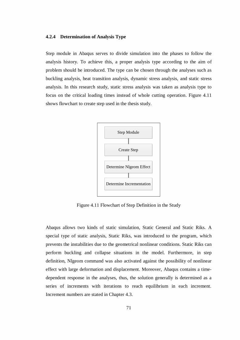
71
4.2.4 Determination of Analysis Type
Step module in Abaqus serves to divide simulation into the phases to follow the
analysis history. To achieve this, a proper analysis type according to the aim of
problem should be introduced. The type can be chosen through the analyses such as
buckling analysis, heat transition analysis, dynamic stress analysis, and static stress
analysis. In this research study, static stress analysis was taken as analysis type to
focus on the critical loading times instead of whole cutting operation. Figure 4.11
shows flowchart to create step used in the thesis study.
Create Step
Step Module
Determine Nlgeom Effect
Determine Incrementation
Figure 4.11 Flowchart of Step Definition in the Study
Abaqus allows two kinds of static simulation, Static General and Static Riks. A
special type of static analysis, Static Riks, was introduced to the program, which
prevents the instabilities due to the geometrical nonlinear conditions. Static Riks can
perform buckling and collapse situations in the model. Furthermore, in step
definition, Nlgeom command was also activated against the possibility of nonlinear
effect with large deformation and displacement. Moreover, Abaqus contains a time-
dependent response in the analyses, thus, the solution generally is determined as a
series of increments with iterations to reach equilibrium in each increment.
Increment numbers are stated in Chapter 4.3.
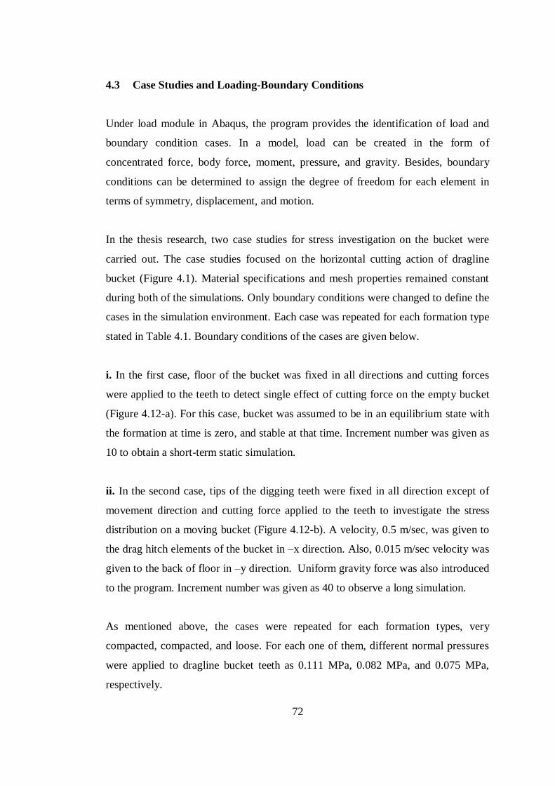
72
4.3 Case Studies and Loading-Boundary Conditions
Under load module in Abaqus, the program provides the identification of load and
boundary condition cases. In a model, load can be created in the form of
concentrated force, body force, moment, pressure, and gravity. Besides, boundary
conditions can be determined to assign the degree of freedom for each element in
terms of symmetry, displacement, and motion.
In the thesis research, two case studies for stress investigation on the bucket were
carried out. The case studies focused on the horizontal cutting action of dragline
bucket (Figure 4.1). Material specifications and mesh properties remained constant
during both of the simulations. Only boundary conditions were changed to define the
cases in the simulation environment. Each case was repeated for each formation type
stated in Table 4.1. Boundary conditions of the cases are given below.
i. In the first case, floor of the bucket was fixed in all directions and cutting forces
were applied to the teeth to detect single effect of cutting force on the empty bucket
(Figure 4.12-a). For this case, bucket was assumed to be in an equilibrium state with
the formation at time is zero, and stable at that time. Increment number was given as
10 to obtain a short-term static simulation.
ii. In the second case, tips of the digging teeth were fixed in all direction except of
movement direction and cutting force applied to the teeth to investigate the stress
distribution on a moving bucket (Figure 4.12-b). A velocity, 0.5 m/sec, was given to
the drag hitch elements of the bucket in –x direction. Also, 0.015 m/sec velocity was
given to the back of floor in –y direction. Uniform gravity force was also introduced
to the program. Increment number was given as 40 to observe a long simulation.
As mentioned above, the cases were repeated for each formation types, very
compacted, compacted, and loose. For each one of them, different normal pressures
were applied to dragline bucket teeth as 0.111 MPa, 0.082 MPa, and 0.075 MPa,
respectively.
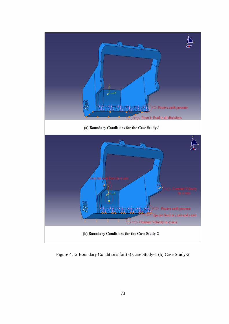
73
Figure 4.12 Boundary Conditions for (a) Case Study-1 (b) Case Study-2
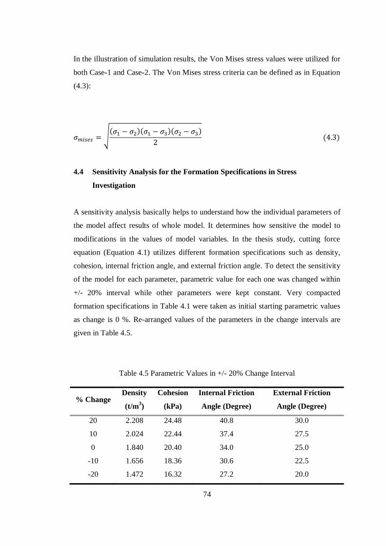
74
In the illustration of simulation results, the Von Mises stress values were utilized for
both Case-1 and Case-2. The Von Mises stress criteria can be defined as in Equation
(4.3):
√( )( )( )
( )
4.4 Sensitivity Analysis for the Formation Specifications in Stress
Investigation
A sensitivity analysis basically helps to understand how the individual parameters of
the model affect results of whole model. It determines how sensitive the model to
modifications in the values of model variables. In the thesis study, cutting force
equation (Equation 4.1) utilizes different formation specifications such as density,
cohesion, internal friction angle, and external friction angle. To detect the sensitivity
of the model for each parameter, parametric value for each one was changed within
+/- 20% interval while other parameters were kept constant. Very compacted
formation specifications in Table 4.1 were taken as initial starting parametric values
as change is 0 %. Re-arranged values of the parameters in the change intervals are
given in Table 4.5.
Table 4.5 Parametric Values in +/- 20% Change Interval
% Change Density
(t/m3)
Cohesion
(kPa)
Internal Friction
Angle (Degree)
External Friction
Angle (Degree)
20 2.208 24.48 40.8 30.0
10 2.024 22.44 37.4 27.5
0 1.840 20.40 34.0 25.0
-10 1.656 18.36 30.6 22.5
-20 1.472 16.32 27.2 20.0
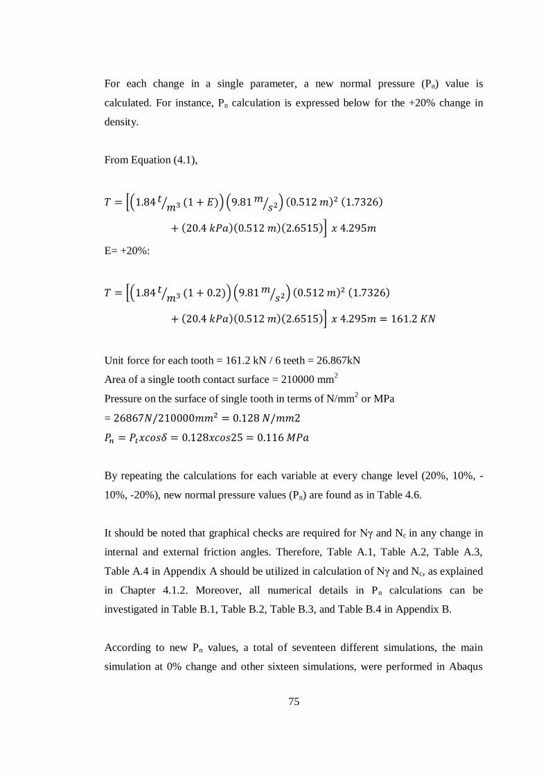
75
For each change in a single parameter, a new normal pressure (Pn) value is
calculated. For instance, Pn calculation is expressed below for the +20% change in
density.
From Equation (4.1),
*( ⁄ ( )) ( ⁄ ) ( ) ( )
( )( )( )+
E= +20%:
*( ⁄ ( )) ( ⁄ ) ( ) ( )
( )( )( )+
Unit force for each tooth = 161.2 kN / 6 teeth = 26.867kN
Area of a single tooth contact surface = 210000 mm2
Pressure on the surface of single tooth in terms of N/mm2 or MPa
=
By repeating the calculations for each variable at every change level (20%, 10%, -
10%, -20%), new normal pressure values (Pn) are found as in Table 4.6.
It should be noted that graphical checks are required for Nγ and Nc in any change in
internal and external friction angles. Therefore, Table A.1, Table A.2, Table A.3,
Table A.4 in Appendix A should be utilized in calculation of Nγ and Nc, as explained
in Chapter 4.1.2. Moreover, all numerical details in Pn calculations can be
investigated in Table B.1, Table B.2, Table B.3, and Table B.4 in Appendix B.
According to new Pn values, a total of seventeen different simulations, the main
simulation at 0% change and other sixteen simulations, were performed in Abaqus
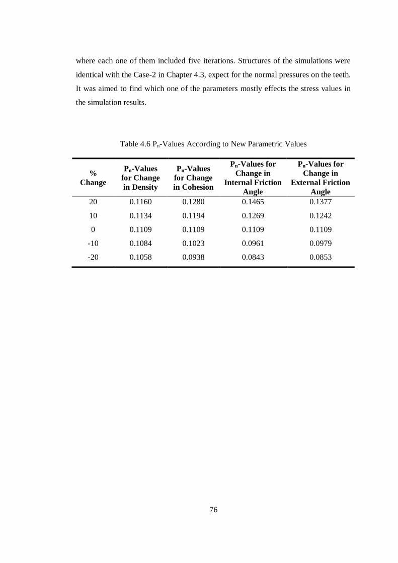
76
where each one of them included five iterations. Structures of the simulations were
identical with the Case-2 in Chapter 4.3, expect for the normal pressures on the teeth.
It was aimed to find which one of the parameters mostly effects the stress values in
the simulation results.
Table 4.6 Pn-Values According to New Parametric Values
%
Change
Pn-Values
for Change
in Density
Pn-Values
for Change
in Cohesion
Pn-Values for
Change in
Internal Friction
Angle
Pn-Values for
Change in
External Friction
Angle
20 0.1160 0.1280 0.1465 0.1377
10 0.1134 0.1194 0.1269 0.1242
0 0.1109 0.1109 0.1109 0.1109
-10 0.1084 0.1023 0.0961 0.0979
-20 0.1058 0.0938 0.0843 0.0853
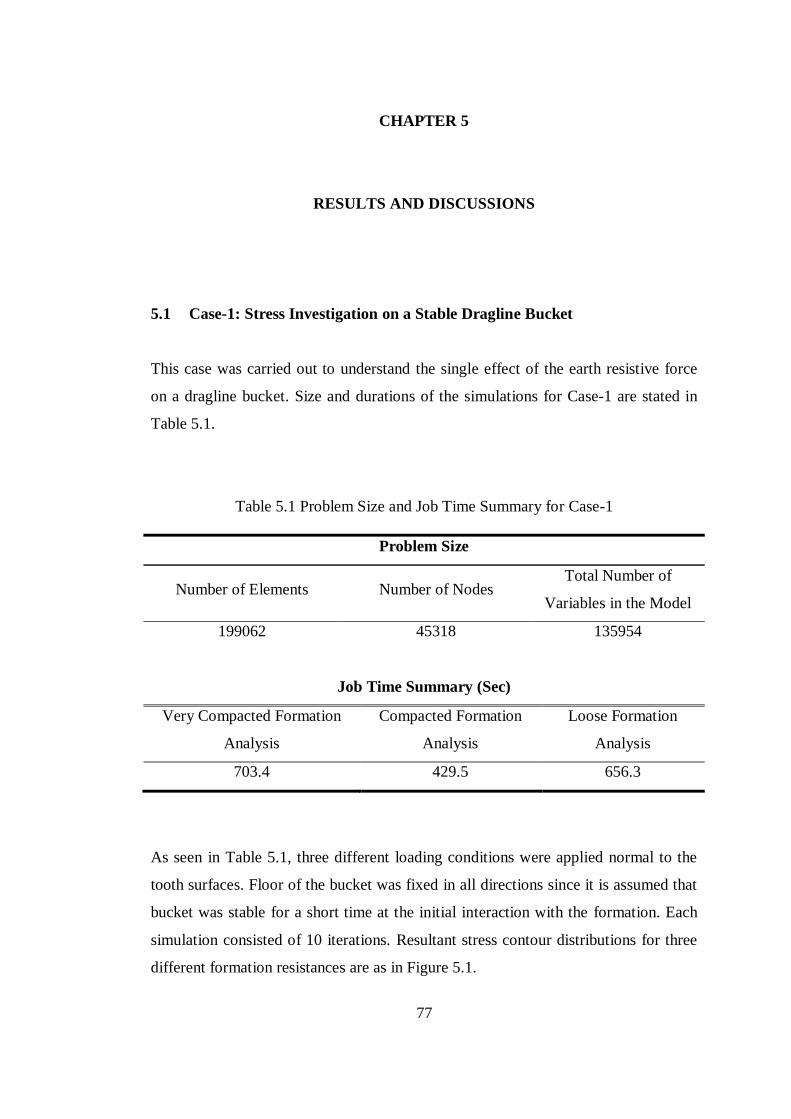
77
CHAPTER 5
5 RESULTS AND DISCUSSIONS
5.1 Case-1: Stress Investigation on a Stable Dragline Bucket
This case was carried out to understand the single effect of the earth resistive force
on a dragline bucket. Size and durations of the simulations for Case-1 are stated in
Table 5.1.
Table 5.1 Problem Size and Job Time Summary for Case-1
Problem Size
Number of Elements Number of Nodes Total Number of
Variables in the Model
199062 45318 135954
Job Time Summary (Sec)
Very Compacted Formation
Analysis
Compacted Formation
Analysis
Loose Formation
Analysis
703.4 429.5 656.3
As seen in Table 5.1, three different loading conditions were applied normal to the
tooth surfaces. Floor of the bucket was fixed in all directions since it is assumed that
bucket was stable for a short time at the initial interaction with the formation. Each
simulation consisted of 10 iterations. Resultant stress contour distributions for three
different formation resistances are as in Figure 5.1.
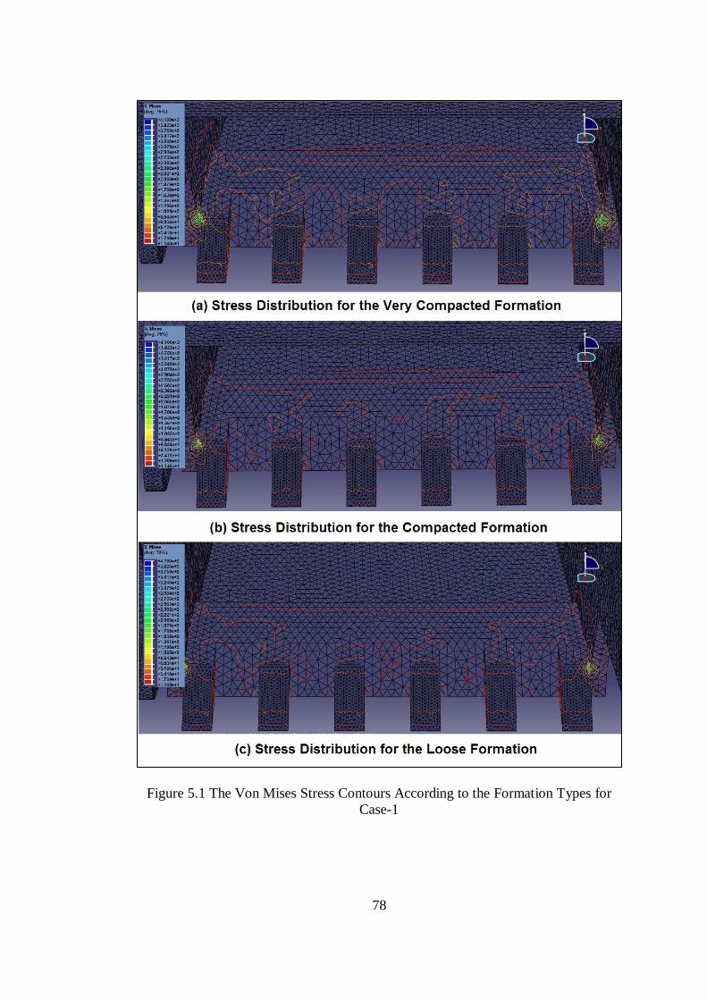
78
Figure 5.1 The Von Mises Stress Contours According to the Formation Types for
Case-1
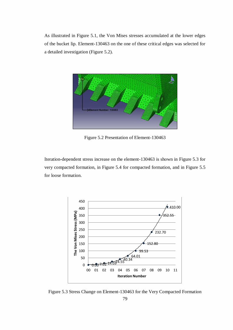
79
As illustrated in Figure 5.1, the Von Mises stresses accumulated at the lower edges
of the bucket lip. Element-130463 on the one of these critical edges was selected for
a detailed investigation (Figure 5.2).
Figure 5.2 Presentation of Element-130463
Iteration-dependent stress increase on the element-130463 is shown in Figure 5.3 for
very compacted formation, in Figure 5.4 for compacted formation, and in Figure 5.5
for loose formation.
Figure 5.3 Stress Change on Element-130463 for the Very Compacted Formation
0.00 7.02 14.03 24.55 40.34
64.01
99.53
152.80
232.70
352.55
410.00
0
50
100
150
200
250
300
350
400
450
00 01 02 03 04 05 06 07 08 09 10 11
The
Vo
n M
ises
Str
ess
(M
Pa)
Iteration Number
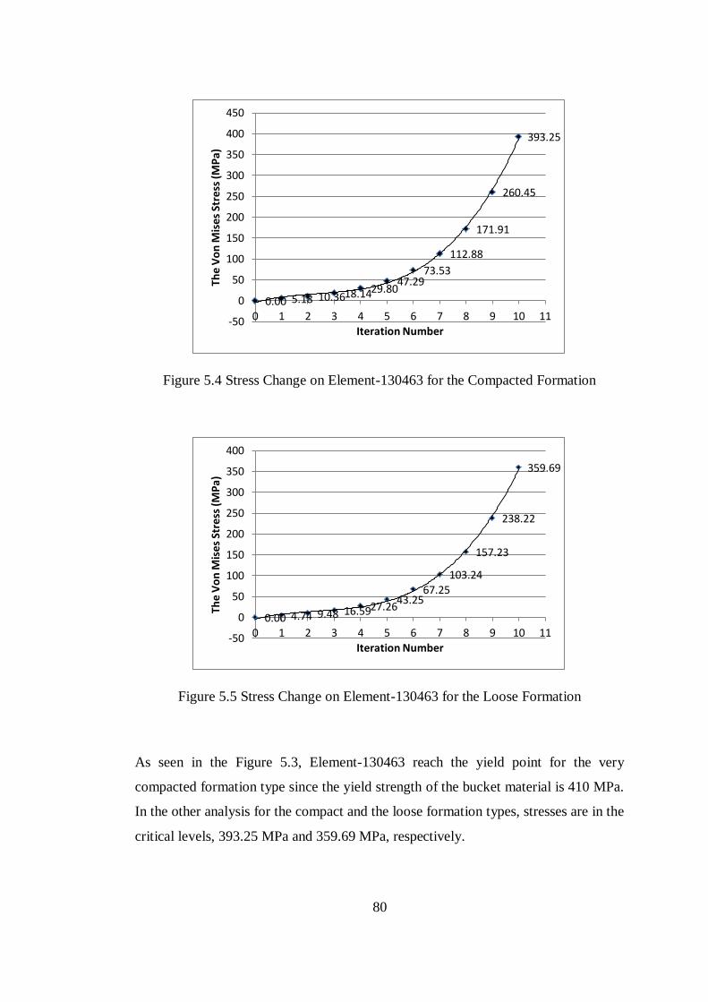
80
Figure 5.4 Stress Change on Element-130463 for the Compacted Formation
Figure 5.5 Stress Change on Element-130463 for the Loose Formation
As seen in the Figure 5.3, Element-130463 reach the yield point for the very
compacted formation type since the yield strength of the bucket material is 410 MPa.
In the other analysis for the compact and the loose formation types, stresses are in the
critical levels, 393.25 MPa and 359.69 MPa, respectively.
0.00 5.18 10.36 18.14 29.80 47.29
73.53
112.88
171.91
260.45
393.25
-50
0
50
100
150
200
250
300
350
400
450
0 1 2 3 4 5 6 7 8 9 10 11
The
Vo
n M
ise
s St
ress
(M
Pa)
Iteration Number
0.00 4.74 9.48 16.59 27.26 43.25
67.25 103.24
157.23
238.22
359.69
-50
0
50
100
150
200
250
300
350
400
0 1 2 3 4 5 6 7 8 9 10 11
The
Vo
n M
ises
Str
ess
(M
Pa)
Iteration Number
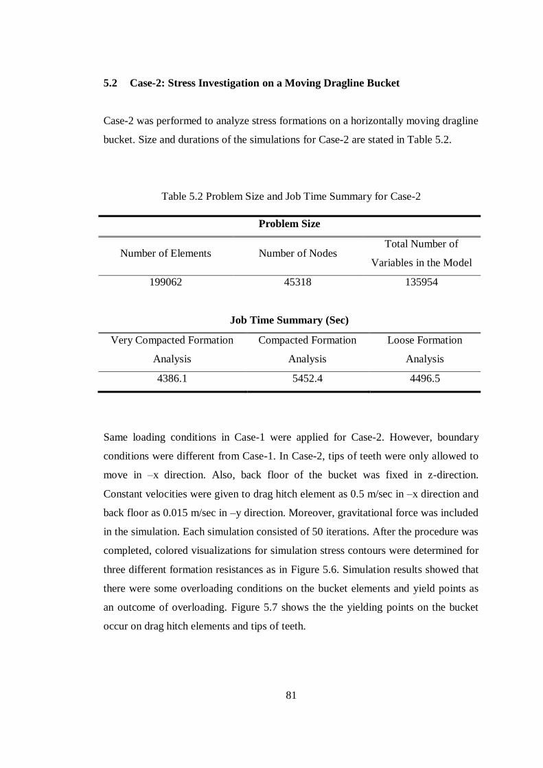
81
5.2 Case-2: Stress Investigation on a Moving Dragline Bucket
Case-2 was performed to analyze stress formations on a horizontally moving dragline
bucket. Size and durations of the simulations for Case-2 are stated in Table 5.2.
Table 5.2 Problem Size and Job Time Summary for Case-2
Problem Size
Number of Elements Number of Nodes Total Number of
Variables in the Model
199062 45318 135954
Job Time Summary (Sec)
Very Compacted Formation
Analysis
Compacted Formation
Analysis
Loose Formation
Analysis
4386.1 5452.4 4496.5
Same loading conditions in Case-1 were applied for Case-2. However, boundary
conditions were different from Case-1. In Case-2, tips of teeth were only allowed to
move in –x direction. Also, back floor of the bucket was fixed in z-direction.
Constant velocities were given to drag hitch element as 0.5 m/sec in –x direction and
back floor as 0.015 m/sec in –y direction. Moreover, gravitational force was included
in the simulation. Each simulation consisted of 50 iterations. After the procedure was
completed, colored visualizations for simulation stress contours were determined for
three different formation resistances as in Figure 5.6. Simulation results showed that
there were some overloading conditions on the bucket elements and yield points as
an outcome of overloading. Figure 5.7 shows the the yielding points on the bucket
occur on drag hitch elements and tips of teeth.
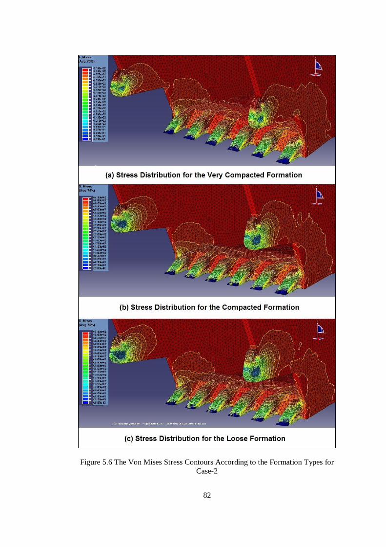
82
Figure 5.6 The Von Mises Stress Contours According to the Formation Types for
Case-2
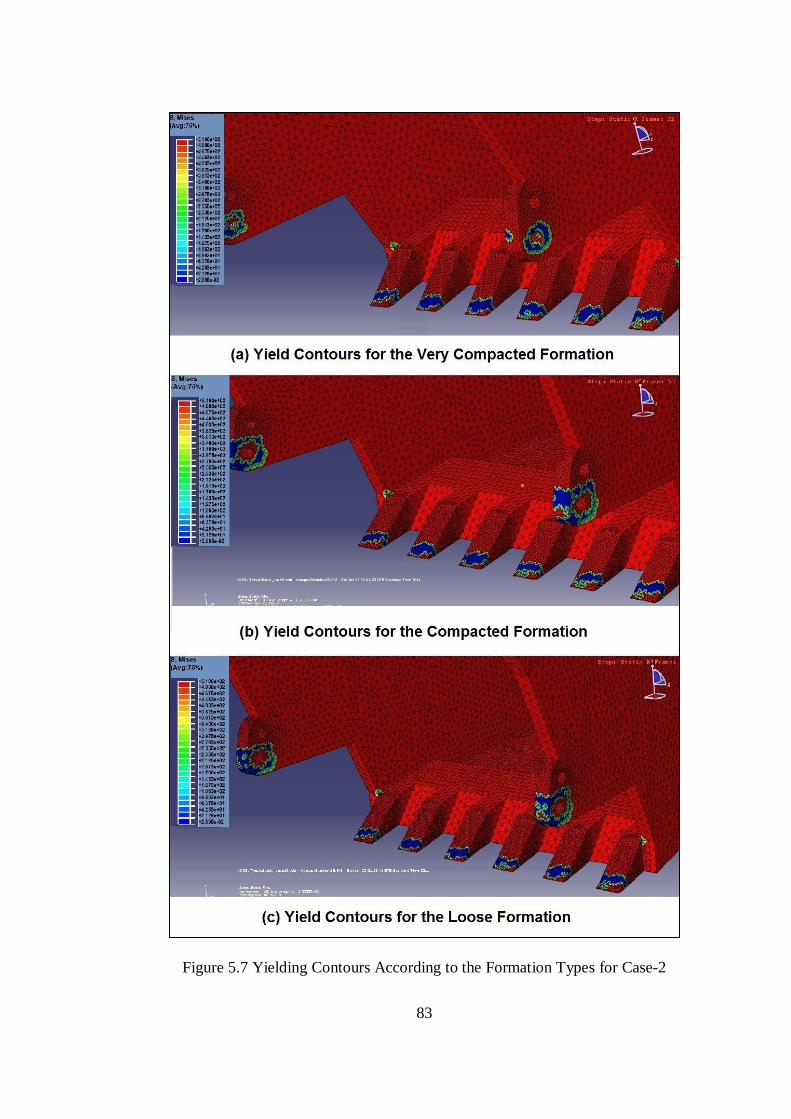
83
Figure 5.7 Yielding Contours According to the Formation Types for Case-2
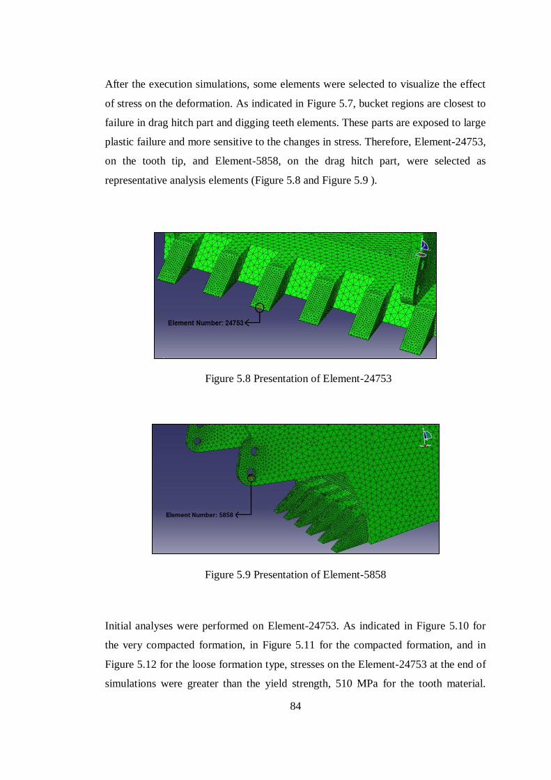
84
After the execution simulations, some elements were selected to visualize the effect
of stress on the deformation. As indicated in Figure 5.7, bucket regions are closest to
failure in drag hitch part and digging teeth elements. These parts are exposed to large
plastic failure and more sensitive to the changes in stress. Therefore, Element-24753,
on the tooth tip, and Element-5858, on the drag hitch part, were selected as
representative analysis elements (Figure 5.8 and Figure 5.9 ).
Figure 5.8 Presentation of Element-24753
Figure 5.9 Presentation of Element-5858
Initial analyses were performed on Element-24753. As indicated in Figure 5.10 for
the very compacted formation, in Figure 5.11 for the compacted formation, and in
Figure 5.12 for the loose formation type, stresses on the Element-24753 at the end of
simulations were greater than the yield strength, 510 MPa for the tooth material.
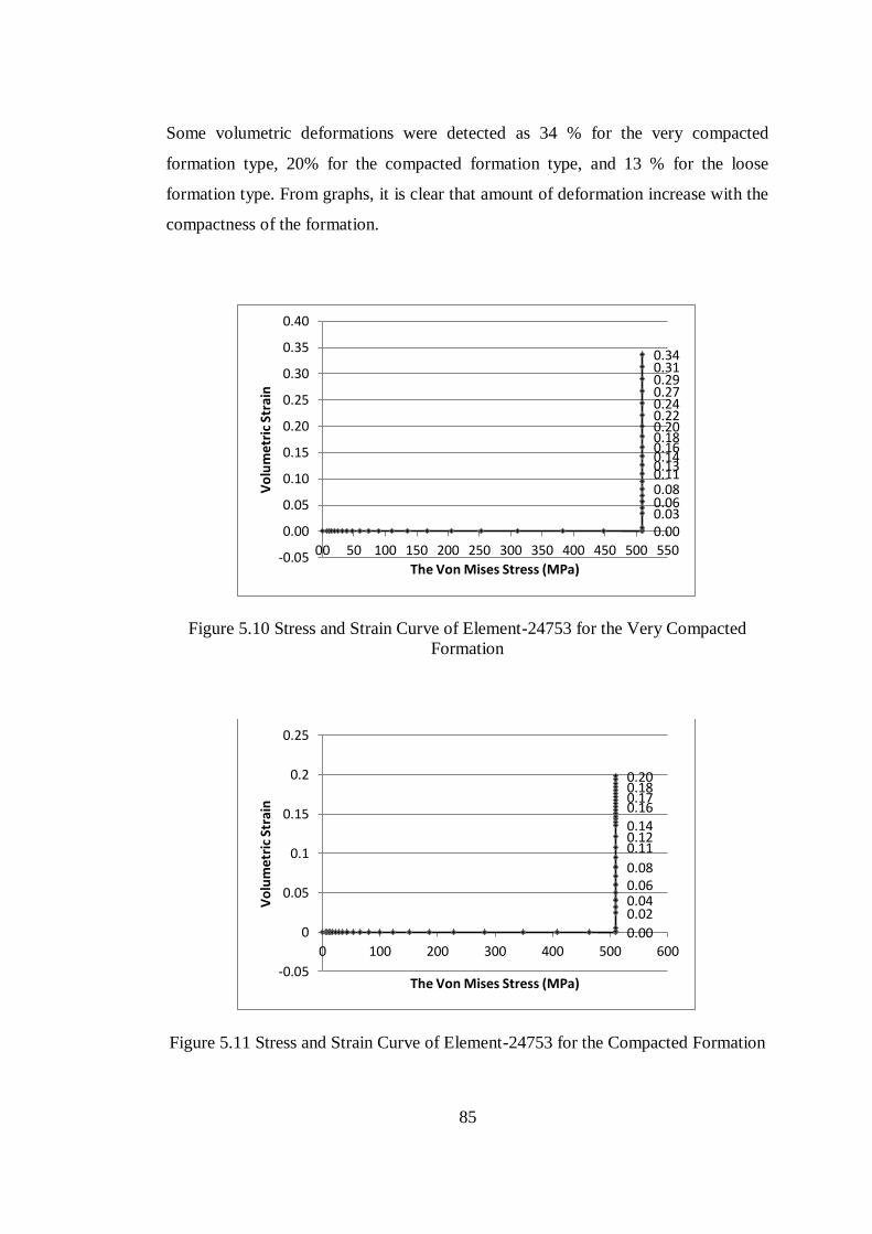
85
Some volumetric deformations were detected as 34 % for the very compacted
formation type, 20% for the compacted formation type, and 13 % for the loose
formation type. From graphs, it is clear that amount of deformation increase with the
compactness of the formation.
Figure 5.10 Stress and Strain Curve of Element-24753 for the Very Compacted
Formation
Figure 5.11 Stress and Strain Curve of Element-24753 for the Compacted Formation
0.00 0.03 0.06 0.08 0.11 0.13 0.14 0.16 0.18 0.20 0.22 0.24 0.27 0.29 0.31 0.34
-0.05
0.00
0.05
0.10
0.15
0.20
0.25
0.30
0.35
0.40
00 50 100 150 200 250 300 350 400 450 500 550
Vo
lum
etr
ic S
tra
in
The Von Mises Stress (MPa)
0.00
0.02 0.04 0.06 0.08
0.11 0.12 0.14 0.16 0.17 0.18 0.20
-0.05
0
0.05
0.1
0.15
0.2
0.25
0 100 200 300 400 500 600
Vo
lum
etri
c St
rain
The Von Mises Stress (MPa)
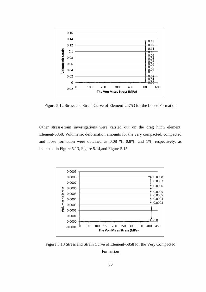
86
Figure 5.12 Stress and Strain Curve of Element-24753 for the Loose Formation
Other stress-strain investigations were carried out on the drag hitch element,
Element-5858. Volumetric deformation amounts for the very compacted, compacted
and loose formation were obtained as 0.08 %, 0.8%, and 1%, respectively, as
indicated in Figure 5.13, Figure 5.14,and Figure 5.15.
Figure 5.13 Stress and Strain Curve of Element-5858 for the Very Compacted
Formation
0.00 0.01 0.02 0.03 0.04 0.05 0.06 0.07 0.08 0.09 0.10 0.11 0.12 0.13
-0.02
0
0.02
0.04
0.06
0.08
0.1
0.12
0.14
0.16
0 100 200 300 400 500 600
Vo
lum
etr
ic S
tra
in
The Von Mises Stress (MPa)
0.0
0.0003 0.0004 0.0005 0.0005
0.0006
0.0007 0.0008
-0.0001
0.0000
0.0001
0.0002
0.0003
0.0004
0.0005
0.0006
0.0007
0.0008
0.0009
0 50 100 150 200 250 300 350 400 450
Vo
lum
etri
c St
rain
The Von Mises Stress (MPa)
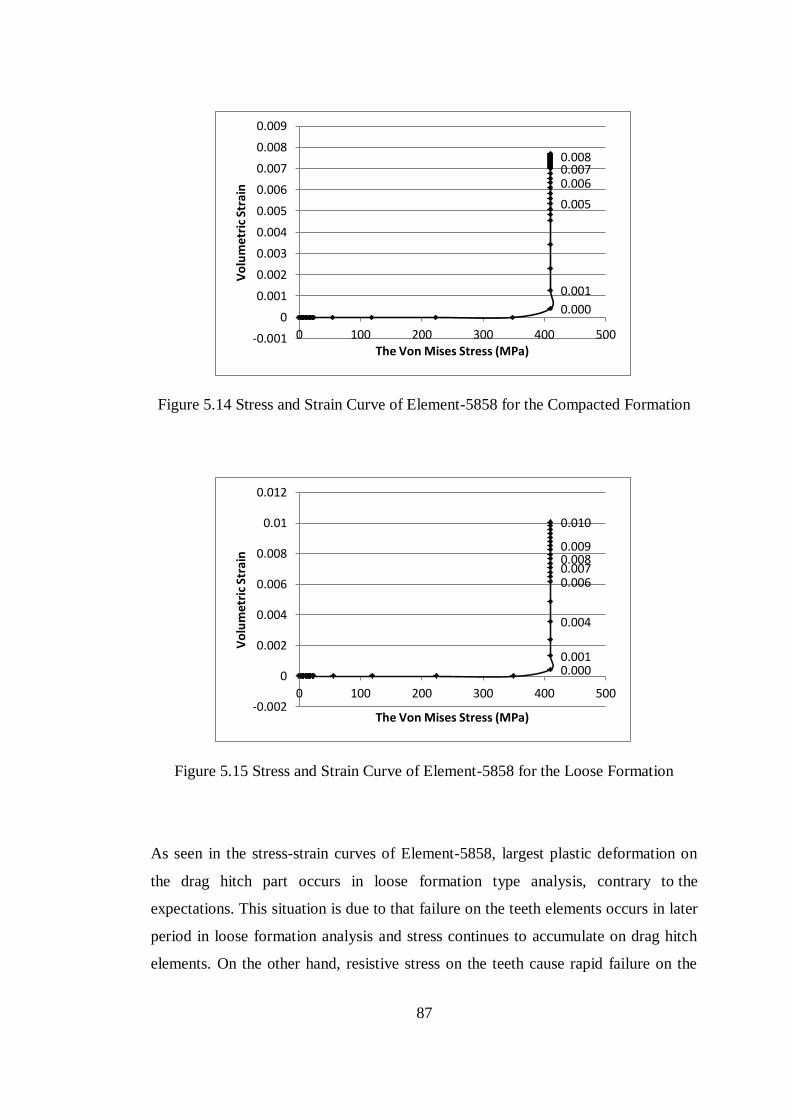
87
Figure 5.14 Stress and Strain Curve of Element-5858 for the Compacted Formation
Figure 5.15 Stress and Strain Curve of Element-5858 for the Loose Formation
As seen in the stress-strain curves of Element-5858, largest plastic deformation on
the drag hitch part occurs in loose formation type analysis, contrary to the
expectations. This situation is due to that failure on the teeth elements occurs in later
period in loose formation analysis and stress continues to accumulate on drag hitch
elements. On the other hand, resistive stress on the teeth cause rapid failure on the
0.000
0.001
0.005
0.006 0.007 0.008
-0.001
0
0.001
0.002
0.003
0.004
0.005
0.006
0.007
0.008
0.009
0 100 200 300 400 500
Vo
lum
etr
ic S
tra
in
The Von Mises Stress (MPa)
0.000 0.001
0.004
0.006 0.007 0.008 0.009
0.010
-0.002
0
0.002
0.004
0.006
0.008
0.01
0.012
0 100 200 300 400 500
Vo
lum
etri
c St
rain
The Von Mises Stress (MPa)
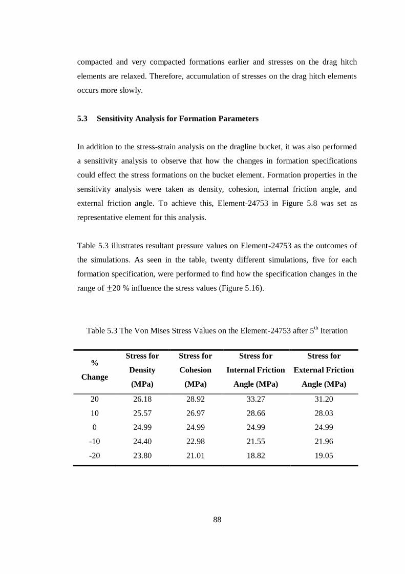
88
compacted and very compacted formations earlier and stresses on the drag hitch
elements are relaxed. Therefore, accumulation of stresses on the drag hitch elements
occurs more slowly.
5.3 Sensitivity Analysis for Formation Parameters
In addition to the stress-strain analysis on the dragline bucket, it was also performed
a sensitivity analysis to observe that how the changes in formation specifications
could effect the stress formations on the bucket element. Formation properties in the
sensitivity analysis were taken as density, cohesion, internal friction angle, and
external friction angle. To achieve this, Element-24753 in Figure 5.8 was set as
representative element for this analysis.
Table 5.3 illustrates resultant pressure values on Element-24753 as the outcomes of
the simulations. As seen in the table, twenty different simulations, five for each
formation specification, were performed to find how the specification changes in the
range of 20 % influence the stress values (Figure 5.16).
Table 5.3 The Von Mises Stress Values on the Element-24753 after 5th Iteration
%
Change
Stress for
Density
(MPa)
Stress for
Cohesion
(MPa)
Stress for
Internal Friction
Angle (MPa)
Stress for
External Friction
Angle (MPa)
20 26.18 28.92 33.27 31.20
10 25.57 26.97 28.66 28.03
0 24.99 24.99 24.99 24.99
-10 24.40 22.98 21.55 21.96
-20 23.80 21.01 18.82 19.05
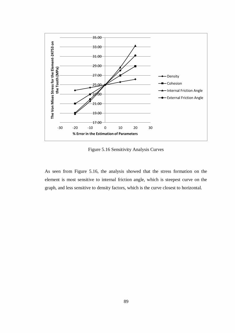
89
Figure 5.16 Sensitivity Analysis Curves
As seen from Figure 5.16, the analysis showed that the stress formation on the
element is most sensitive to internal friction angle, which is steepest curve on the
graph, and less sensitive to density factors, which is the curve closest to horizontal.
17.00
19.00
21.00
23.00
25.00
27.00
29.00
31.00
33.00
35.00
-30 -20 -10 0 10 20 30
The
Vo
n M
ise
s St
ress
fo
r th
e E
lem
en
t-24
753
on
th
e T
oo
th (M
Pa)
% Error in the Estimation of Parameters
Density
Cohesion
Internal Friction Angle
External Friction Angle
90
CHAPTER 6
6 CONCLUSIONS AND RECOMMENDATIONS
6.1 Introduction
In open-cast mines, overburden removal processes are performed by either
excavator-truck system or dragline stripping method. Due to the low maintenance
and operating costs and high production rate, dragline stripping method is preferable
up to 35 m operation height (Köse, 1987). Earthmoving efficiency of a dragline can
be determined by the cycle time utilization and the bucket payload amount (Vynne,
2008). In this regard, the fact that the dragline carries maximum volume of
overburden in minimum cycle time without any catastrophic or machinery failure,
creates most appropriate working condition for a dragline.
Dragline implements the stripping operation with a bucket suspending from the tip
sheaves of the boom. Operator controls the bucket actions with a chain-rope system
called rigging mechanism. Productivity of this earthmover directly depends on the
performances of working parts, especially bucket and rigging mechanism since
interaction between the machine and formation takes place via the bucket. Besides
the diggibility of a bucket is critical for whole dragline productivity, it is also
required to avoid damages on the bucket due to the overloading conditions or
improper bucket selection. Since, these types of failures on bucket elements can
cause long-term breaks and loss of time and production. Previous research studies
about the bucket performance have mainly focused on the topics such as material
filling optimization, rigging mechanism arrangements, kinematical testing of bucket
and automation. Although these studies are for improving bucket efficiency, there is
still a lack of investigation about strain-stress distribution on a working dragline
bucket. Accordingly, formation interaction simulation of dragline bucket in virtual
91
environment is still an emerging research topic on dragline productivity.
Consequently, this research study combines the use of Finite Element Analysis
(FEA), Computer-Aided Design (CAD) and analytical literature review to observe
the stress distribution on a three-dimensional dragline bucket model. Determination
of dragline bucket and rigging mechanism solid models was performed by
Solidworks (Solidworks Co., 2009). Only bucket model was transferred to the
simulation environment to focus on the stress investigation on the bucket and to
eliminate the possible inaccuracies and long simulation time due to curvatures and
the interaction areas between solid parts. Abaqus 6.9-2 (Simulia, 2010) was chosen
as a finite element executer. Two case studies with different boundary conditions
were computed in Abaqus environment, with Static, Riks method. Each simulation
was repeated for three different formation specifications as very compact, compact
and loose formations, respectively.
6.2 Conclusions
First case study, with ten iterations, aimed to measure the single effect of passive
earth pressure magnitude on a fixed bucket. Simulation result showed that lower
edge of the bucket lip fails for the very compacted formation analysis and come to
critical levels for compacted and loose formation types. Second case, with fifty
iterations, allowed investigating stress analysis on a dragline bucket with constant
velocity. In this case, drag hitch parts of the bucket and digging teeth were detected
as failure zones on the bucket. Besides the simulations, a sensitivity analysis was
executed to see the impacts of each formation specification on the stress simulation
findings. The analysis indicated that stress amounts on the elements were mostly
effected by the change in internal friction angle and least effected by the change in
density. Detailed stress analysis on the dragline bucket shows that:
i. Sharp edges on the front of bucket are closest to fail during the operation.
These edges are required to be rounded and strengthened by welding or any
other metallurgical method.
92
ii. Drag hitch element of the bucket and the tips of the digging teeth are most
sensitive parts on the bucket. Stress accumulation mostly occurs in these
sections. A possible overloading dragging condition primarily causes the yields
in these parts.
iii. Internal friction is most significant formation factor to determine the resistive
forces on the bucket. On the other hand, density is least effective to change the
pressure values on the bucket parts.
iv. Defined criteria in the boundary condition and number of the iterations
considerably affect the simulation time and simulation results.
v. Material selections for the solid bodies greatly influence the mechanical
behavior of the parts under loading conditions.
6.3 Recommendations
The main recommendations related to this study are:
i. Three dimensional simulation of whole dragline could be useful to detect all
stress-strain formations on the machine.
ii. Projects which include both industry and university could eliminate the lack of
data in the analysis and help to obtain more realistic simulation results.
iii. Performing computational stress investigation together with field
measurements in the mine site could validate the simulation model.
iv. Fracture and fatigue analysis on the stress-intensive parts of dragline could be
beneficial to investigate the working life of the components. Therefore, more
sensitive performance calculations could be made for the dragline.
v. Virtual reality studies for the dragline operator could be useful for the efficient
training of the operators in safe conditions.
93
7 REFERENCES
Abaqus 6.9 User's Manual. (2009). Elements. 4.
Abaqus 6.9 User's Manual. (2009). Getting Started with Abaqus.
Abo-Elnor, M., Hamilton, R., & Boyle, J. T. (2004). Simulation of Soil–Blade
Interaction for Sandy Soil Using Advanced 3D Finite Element Analysis. Soil
& Tillage Research, 75, 61–73.
Alekseeva, T. V., Artem'ev, K. A., Bromberg, A. A., Voitsekhovskii, R. I., &
Ul'yanov, N. A. (1985). Machines for Earthmoving Work: Theory and
Calculations. Rotterdam: Balkema.
Aluko, O. B. (2008). Finite Element Aided Brittle Fracture Force Estimation During
Two-Dimensional Soil Cutting. International Agrophysics, 22, 5-15.
Aluko, O. B., & Chandler, H. W. (2004). A Fracture Strength Parameter for Brittle
Agricultural Soils. Biosystems Engineering, 88(3), 369-381.
Aluko, O. B., & Seig, D. A. (2000). An Experimental Investigation of the
Characteristics of and Conditions for Brittle Fracture in Two-Dimensional
Soil Cutting. Soil and Tillage Research, 57, 143-157.
Anonymous. (2004). Dragline Excavator. Retrieved August 22, 2010, from
Wikipedia: http://www.enotes.com/topic/Dragline_excavator
Anonymous. (2008). Retrieved December 2010, from
http://www.pbase.com/intermodal/image/99215155/original
Anonymous. (2010, March 31). Arch Western Resources Annual Report- Form
NO:10-K. Retrieved December 14, 2010, from http://www.faqs.org/sec-
filings/100331/ARCH-WESTERN-RESOURCES-LLC_10-K/
Baafi, E. Y., Mirabediny, H., & Whitchurch, K. (1997). Computer Simulation of
Complex Dragline Operations. International Journal of Surface Mining,
Reclamation and Environment, 11(1), 7-13.
Berg, P. v. (1994). Analysis of Soil Penetration. Stevinweg: Delft University Press.
94
Blouin, S., Hemami, A., & Lipsett, M. (2001). Review of Resistive Force Models for
Earthmoving Processes. Journal of Aerospace Engineering, 102-111.
Bucket and Teeth. (2008, September). Retrieved June 2, 2010, from ESCO
Corporation Web Site:
http://www.escocorp.com/media/articles/ESCO_and_Rosebud_Mine.pdf
Chi, L., & Kushwaha, R. L. (1989). Finite Element Analysis of Forces on A Plane
Soil Blade. Canadian Agricultural Engineering, 31(2), 135-140.
Cleary, P. W. (1998). The Filling of Dragline Buckets. Mathematical Engineering in
Industry, 7(1), 1-24.
Cobcroft, T. (2007). Virtual Reality for Dragline Planners. Coal Age, 22-26.
Coetzee, C. J., Basson, A. H., & Vermeer, P. A. (2007). Discrete and Continuum
Modelling of Excavator Bucket Filling. Journal of Terramechanics, 44, 177–
186.
Corke, P., Winstanley, G., Dunbabin, M., & Roberts, J. (2006). Dragline
Automation: Experimental Evaluation through Productivity Trial. The
International Conference on Field and Service Robotics, (pp. 459-468).
Craig, R. F. (1997). Soil Mechanics. London: Taylor & Francis Group.
Davis, M. (2010, June). Photograph of Bucyrus Erie 2550-W Walking Dragline.
Retrieved December 2010, from
http://www.flickr.com/photos/perspectivephotography/5055431041/
Davoudi, S., Alimardani, R., Keyhani, A., & Atarnejad, R. (2008). A Two
Dimensional Finite Element Analysis of a Plane Tillage Tool in Soil Using a
Non-linear Elasto-Plastic Model. American-Eurasian Journal of Agricultural
& Environmental Sc, 3(3), 498-505.
Dayawansa, P., Chitty, G., Kerezsi, B., Bartosiewicz, H., & Price, J. W. (2003). The
Cracking of Clusters in Mining Dragline Booms: Causes and Responses.
Proceedings of International Conference on Failure Analysis and
Maintenance Technologies.
Demirel, N. (2009). Çekme-Kepçe Performansını Etkileyen Operasyonel Faktörler.
95
Türkiye 2. Maden Makinaları Sempozyumu Bildiriler Kitabı, (pp. 267-276).
Zonguldak.
Demirel, N. E. (2007). Dynamic Dragline Modeling and Boom Stress Analysis for
Efficient Excavation. PHD Thesis.
Dragline Excavator. (n.d.). Retrieved May 15, 2010, from Wikipedia Online
Encyclopedia: http://en.wikipedia.org/wiki/Dragline_excavator
Dragline Methods. (n.d.). Retrieved May 3, 2010, from United States Environmental
Protection Agency Web Site: epa.gov/region3/mtntop/pdf/appendices/h/mrt-
symposium/fugpres1.pdf
Erdem, B., Çelebi, N., & PaĢamehmetoğlu, A. G. (1998). Ġkili Dragline
Sistemlerinde Dragline EĢzamanlanmasına Yönelik Bir YaklaĢım. Türkiye
11. Kömür Kongresi Bildiriler Kitabı, (pp. 145-154). Amasra.
Erdem, B., Duran, Z., & Çelebi, N. (2004). A Model for Direct Dragline Casting in a
Dipping Coal-Seam. The Journal of The South African Institute of Mining
and Metallurgy, 9-16.
Erdem, B., NeĢ'e, Ç., & PaĢamehmetoğlu, A. G. (2005). Dragline Yığın Kümesi
Tasarımı Ġçin Bilgisayar Destekli Bir YaklaĢım. Türkiye 19. Uluslararası
Madencilik Kongresi ve Fuarı, (pp. 113-123). Ġzmir.
Erdem, B., ġahin, S., & Duran, Z. (2005). Dragline Yığın Kümesi Tasarımı Ġçin
Bilgisayar Destekli Bir YaklaĢım. Türkiye 19. Uluslararası Madencilik
Kongresi ve Fuarı Bildiriler Kitabı, (pp. 113-123). Ġzmir.
Ericsson, A., & Slattengren, J. (2000). A Model for Predicting Digging Forces When
Working in Gravel or Other Granulated Material. (pp. 1-9). Rome: 15th
ADAMS European Users Conferance Proceedings.
Esco Dragline Buckets. (2010). ESCO ProFill™ Dragline Bucket. Retrieved
December 2010, from Esco Corporation Official Website:
http://www.escocorp.com/markets/mining/dragline_buckets.html
Fielke, J. M. (1999). Finite Element Modelling of the Interaction of the Cutting Edge
of Tillage Implements with Soil. Journal of Agricultural Engineering
96
Research, 74, 91-101.
Genç, M. (2002). Computer aided Modeling Of Dragline Operation In Open Pits And
Investigation of Dragline Applications in Western Anatolia. D.E.Ü Mining
Engineering Department Msc Thesis.
Gilewicz, P. (1999, August). U.S. Dragline Census . Coal Age, 104(8).
Gilewicz, P. (2000). International Dragline Population Matures. Coal Age, 105(6),
30-32.
Gill, W. R., & Vanden Berg, G. E. (1968). Soil Dynamics in Tillage and Traction.
Washington, U.S.A.: Agricultural Research Service.
Gurgenci, H., & Guan, Z. (2001). Mobile Plant Maintenance and the Dutymeter
Concept. Journal of Quality in Maintenance Engineering, 7, 275-285.
Hartman, H. L. (Ed.). (1992). SME Mining Engineering Handbook (2nd Edition ed.,
Vol. 1). Society for Mining, Metallurgy, and Exploration, Inc.
Hartman, H. L., & Mutmansky, J. M. (2002). Introductory Mining Engineering (2nd
Edition ed.). John Wiley and Sons, Inc.
Hemami, A., Goulet, S., & Aubertin, M. (1994). Resistance of Particulate Media to
Excavation: Application to Bucket Loading. International Journal of Surface
Mining, Reclamation and Environment , 8, 125-129.
Hettiaratchi, D., & Reece, A. (1974). The Calculation of Passive Soil Resistance.
Geotechnique, 24(3), 289-310.
Hofstetter, K. (2002). Analytic Method to Predict the Dynamic Interaction of Dozer
Blade with Earthen Material. Proceedings of the 14th International
Conference of the ISTVS. Vicksburg.
Kannan, G., Schmitz, L., & Larsen, C. (2000). An Industry Perspective On The Role
Of Equipment Based Earthmoving Simulation. Proceedings of Simulation
Conference, 2, pp. 1945-1952.
Kavetsky, A. (1999). Modeling Dragline Bucket Dynamics and Digging (including
Bucket Filling Animations CD). Report No: C3048, Australian Coal
97
Association Research Program (ACARP).
Kennedy, B. A. (1990). Surface Mining (2nd Edition ed.). Society for Mining,
Metallurgy, and Exploration, Inc .
Köse, H., & Yalçın, C. (1985). Örtü Kazı Yöntemlerinin Ekonomik Açıdan
Değerlendirilmesi. Ġzmir: DEÜ Maden Mühendisliği Bölümü.
Legg, T., Dymond, G., & Eeden, J. v. (2008). Taper VS. Conventional Bucket. VR
Steel.
Lever, P. (2003, April). Open Cut Automation Scoping Study. Retrieved from
Australian Coal Association Research Program (ACARP) Web Site:
http://www.acarp.com.au/abstracts.aspx?repId=C11054
Maciejewski, J., & Jarzebowski, A. (2002). Laboratory Optimization of the Soil
Digging Process. 39, 161-179.
Matt, W., Blair, J., & McGovern, P. (1997). Determining the Functionality ofa
Dragline Training Simulator. Retrieved from
http://www.findtoyou.com/ebook/dragline+method.html
McKyes, E. (1985). Soil Cutting and Tillage. Retrieved from McGill Bioresource
Engineering Website: http://www.mcgill.ca/files/bioeng/BREE512_part1.pdf
Meyers, T., & Leslie, B. (2001, August). Optimised Bucket for Parallel/Universal
Rig. Retrieved August 2010, from Australian Coal Association Research
Program (ACARP) Web Site:
http://www.acarp.com.au/abstracts.aspx?repId=C10034
Mirabediny, H., & Baafi, E. Y. (1998). Dragline Digging Methods in Australian Strip
Mines - A Survey. Coal Operators' Conference , (pp. 313-324). Wollongong.
Mootaz, A. E., Hamilton, R., & Boyle, J. T. (2003). 3D Dynamic Analysis of Soil–
Tool Interaction Using the Finite Element Method. Journal of
Terramechanics, 40, 51-62.
Mouazen, A. M., & Nemenyi, M. (1999, July). Finite Element Analysis of Subsoiler
Cutting in Non-Homogeneous. Soil and Tillage Research, 51, 1-15.
98
Nedoredzov, I. (1992). Forces Prediction of Underwater Soil Cutting by Excavating
Robots. 9th International Symposium on Automation and Construction.
Tokyo.
O'Beirne, T., & Lumley, G. (1997, July). Improved Dragline Productivity Through
Rigging Design. Retrieved June 2010, from Australian Coal Association
Research Program (ACARP) Web Site:
http://www.acarp.com.au/abstracts.aspx?repId=C4003
Offei, K. A., & Frimpong, S. (2009). Formation Excavation Resistance Modelling
for Shovel Dippers. International Journal of Mining and Mineral
Engineering, 1(2), 127-146.
Osman, M. S. (1964). The Mechanics of Soil Cutting Blades. Journal of Agricultural
Engineering Research, 9(4), 313-328.
Owen, D., Feng, R. J., Neto, T., Cottrell, E. A., Wang, M., Pires, F. M., et al. (2002).
The modeling of Multi-Fracturing Solids and Particulate Media. Proceedings
of the 5th World Congress on Computational Mechanics. Vienna.
Özdoğan, M. (1984). Çekmekepçe (Dragline) Örtükazı Yöntemleri ve Tunçbilek
Uygulaması. Madencilik, 23(2), 25-42.
Özdoğan, M. (2003). Dragline Yerkazarlarda Kepçe SaplanıĢ Mekanizması ve
Kuvveti. Madencilik, 42(1), 17-26.
Parlak, T. (1985). Açık Kömür ĠĢletmeciliğinde Yerinde Dragline Ġncelenen Dragline
Uygulamaları. Madencilik, 24(2), 5-34.
Raper, R. L., & Erbach, D. C. (1990). Prediction of Soil Stresses Using the Finite
Element Method. Transactions of the ASAE, 33(3), 725-730.
Ridley, P., & Algra, R. (2004). Dragline Bucket and Rigging Dynamics. Mechanism
and Machine Theory, 39, 999-1016.
Rowlands, J. (2000, March). Dragline Rigging and Control System for Universal Dig
& Dump. Retrieved August 20, 2010, from Australian Coal Association
Research Program (ACARP) Web Site:
http://www.acarp.com.au/abstracts.aspx?repId=C9039
99
Ryerson, R. (1980). Patent No. 4233761. United States of America.
Singh, S. (1997). The State of the Art in Automation of Earthmoving. Journal of
Aerospace Engineering, 10(4), 1-29.
Srour, J. (1999, March). evelopment of Tools and Methods for Rigging Data
Specification for use in Dragline Bucket Simulation. Retrieved August 2010,
from Australian Coal Association Research Program (ACARP) Web Site:
http://www.acarp.com.au/abstracts.aspx?repId=C6010
Swick, W. C., & Perumpral, J. V. (1988). A Model for Predicting Soil-Tool
Interaction. Journal of Terramechanics, 25(1), 43-56.
Townson, P., Murthy, P., Guan, Z., & Gurgenci, H. (2001, January). Optimisation of
Design Load Levels for Dragline Buckets. Retrieved June 2010, from
Australian Coal Association Research Program (ACARP) Web Site:
http://www.acarp.com.au/abstracts.aspx?repId=C7003
Vynne, J. F. (2008, May). Innovative Dragline Monitoring Systems and
Technologies. Retrieved August 25, 2010, from
http://tbirdpac.com/support/pdf/innovativedraglinevynne.pdf
WCI Energy Excellence Programme Case Study. (2008, 11). Retrieved May 6, 2010,
from World Coal Institute Official Website:
http://www.worldcoal.org/resources/case-studies/energy-excellence-
programme/
Weber, R. P. (n.d.). Earth Pressure and Retaining Wall Basics for Non-Geotechnical
Engineers. Retrieved June 6, 2010, from PDH Online Courses c155 Lecture
Notes: http://www.pdhonline.org/courses/c155/c155content.pdf
Wilkinson, A., & DeGennaro, A. (2007). Digging and Pushing Lunar Regolith:
Classical Soil Mechanics and the Forces Needed for Excavation and Traction.
Journal of Terramechanics, 44, 133–152.
Worley, M. D., & Saponara, V. L. (2008, May 9). A Simplified Dyanamic Model for
Front-End Loader Design. Journal of Mechanical Engineering Science, 222,
2231-2249.
100
Young, R., & Hanna, A. (1977, September). Finite Element Analysis of Plane Soil
Cutting. Journal of Terramechanics, 14(3), 103-125.
Yu, H. S., & Mitchell, J. K. (1998, February). Analysis of Cone Resistance: Review
of Methods. Retrieved September 15, 2010, from
http://www.scribd.com/doc/22892133/analysis-of-cone-resistance-review-of-
methods
Zelenin, A. N., Balovnev, V. I., & Kerov, L. P. (1986). Machines for Moving the
Earth. Rotterdam: Balkema.
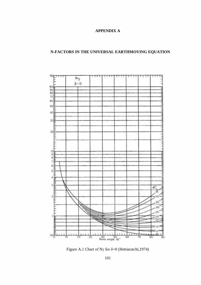
101
APPENDIX A
A. N-FACTORS IN THE UNIVERSAL EARTHMOVING EQUATION
Figure A.1 Chart of N for δ=0 (Hettiaratchi,1974)
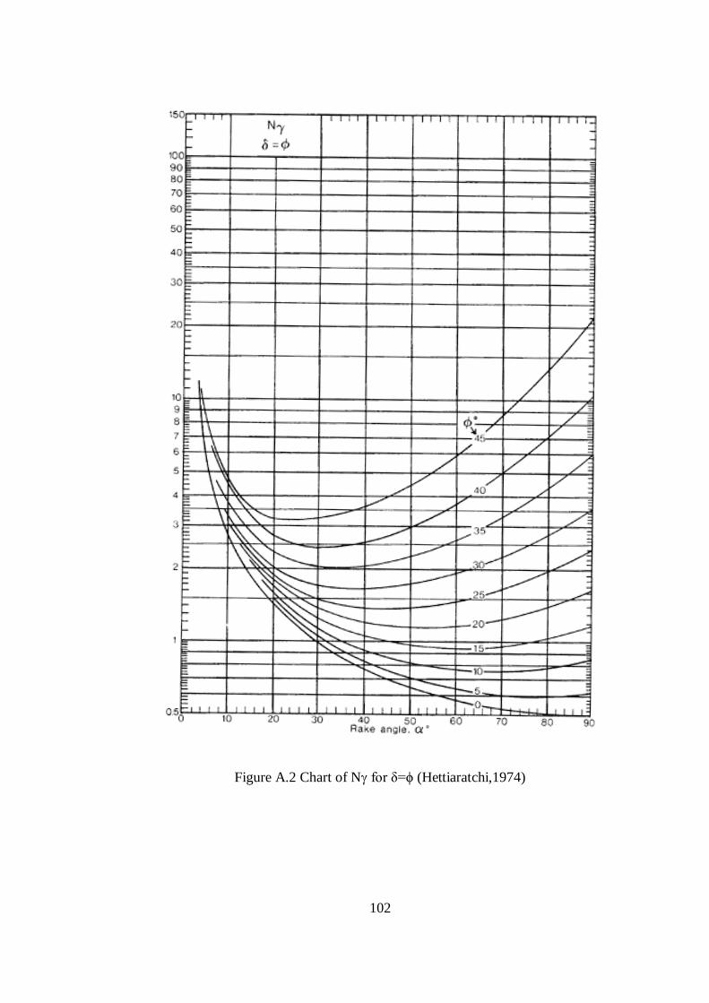
102
Figure A.2 Chart of N for δ=ϕ (Hettiaratchi,1974)
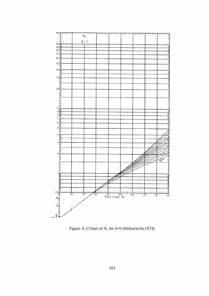
103
Figure A.3 Chart of Nc for δ=0 (Hettiaratchi,1974)
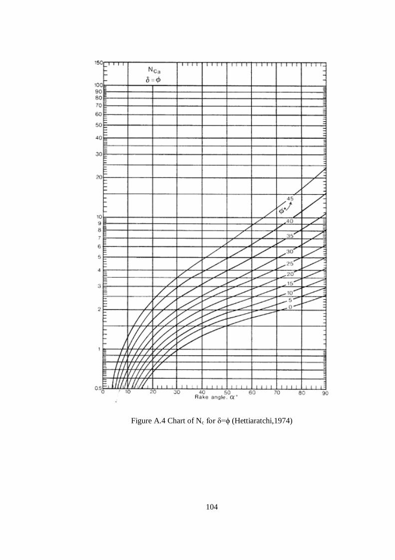
104
Figure A.4 Chart of Nc for δ=ϕ (Hettiaratchi,1974)
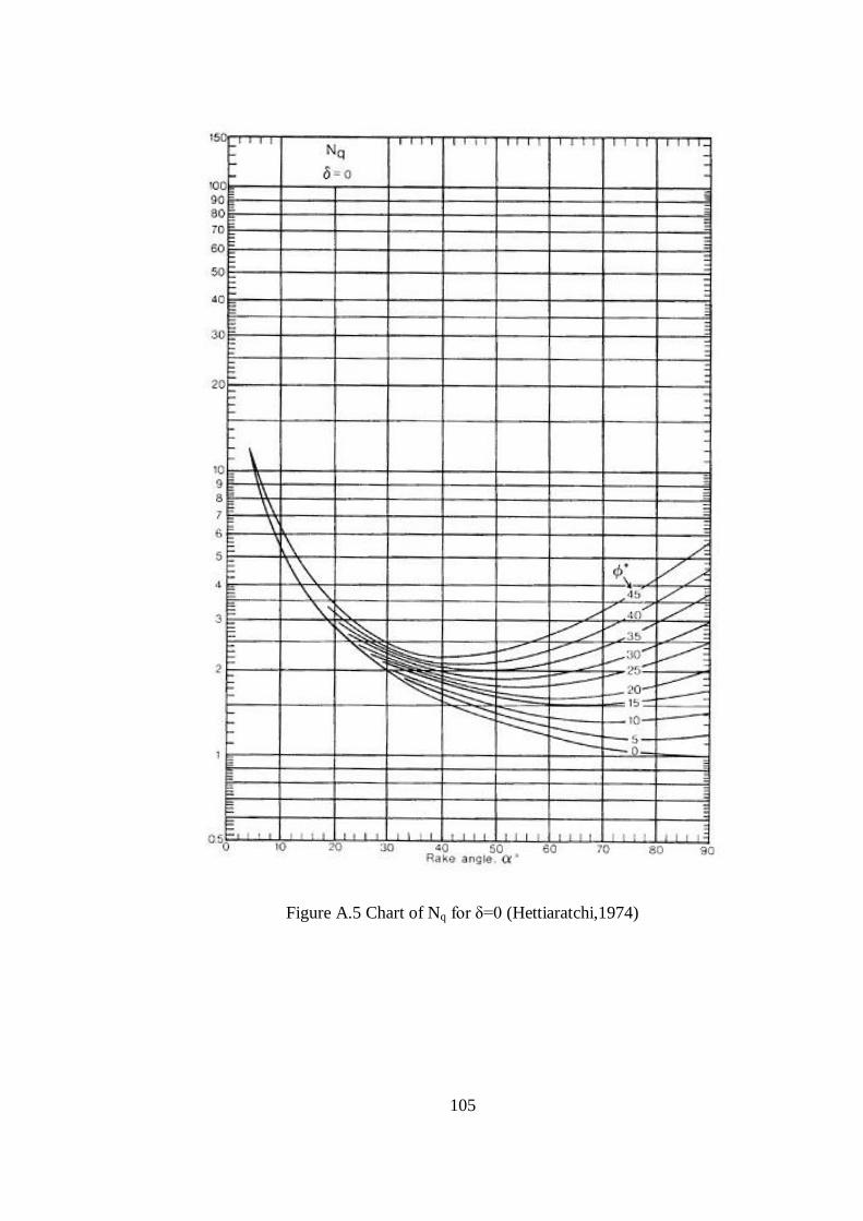
105
Figure A.5 Chart of Nq for δ=0 (Hettiaratchi,1974)
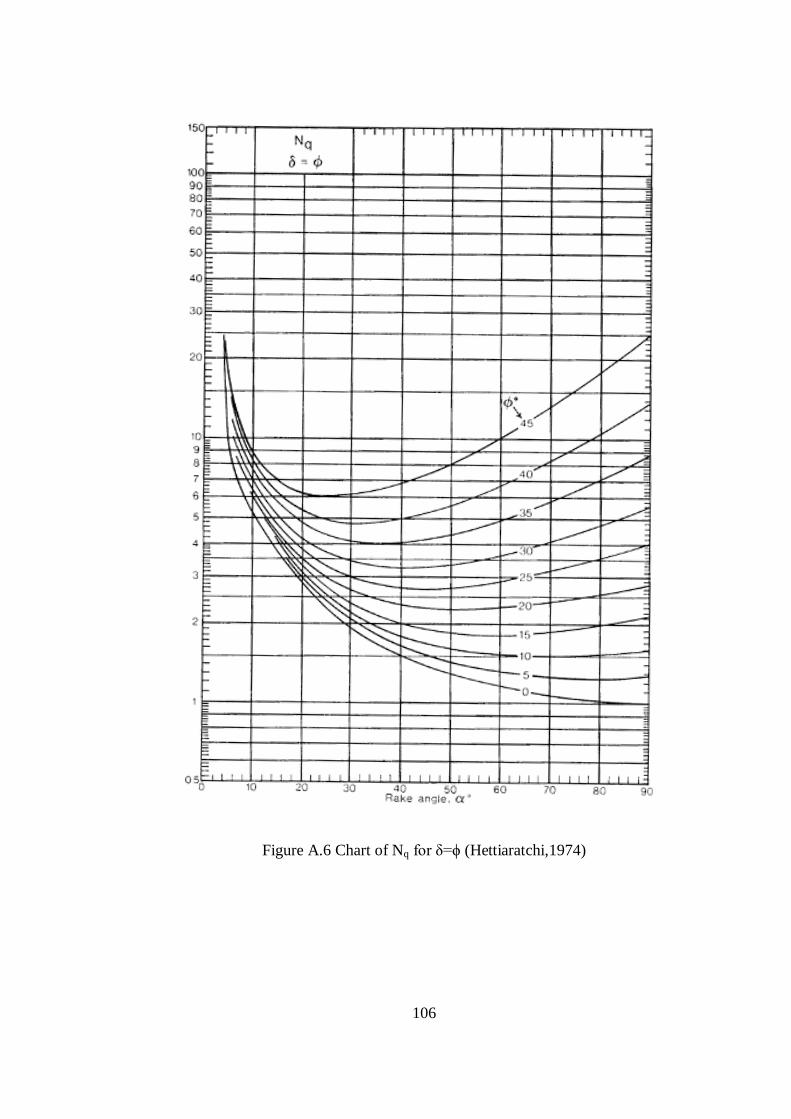
106
Figure A.6 Chart of Nq for δ=ϕ (Hettiaratchi,1974)
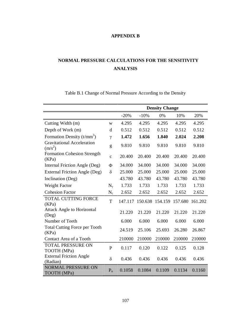
107
APPENDIX B
B. NORMAL PRESSURE CALCULATIONS FOR THE SENSITIVITY
ANALYSIS
Table B.1 Change of Normal Pressure According to the Density
Density Change
-20% -10% 0% 10% 20%
Cutting Width (m) w 4.295 4.295 4.295 4.295 4.295
Depth of Work (m) d 0.512 0.512 0.512 0.512 0.512
Formation Density (t/mm3) γ 1.472 1.656 1.840 2.024 2.208
Gravitational Acceleration
(m/s2)
g 9.810 9.810 9.810 9.810 9.810
Formation Cohesion Strength
(KPa) c 20.400 20.400 20.400 20.400 20.400
Internal Friction Angle (Deg) 34.000 34.000 34.000 34.000 34.000
External Friction Angle (Deg) δ 25.000 25.000 25.000 25.000 25.000
Inclination (Deg) 43.780 43.780 43.780 43.780 43.780
Weight Factor Nγ 1.733 1.733 1.733 1.733 1.733
Cohesion Factor Nc 2.652 2.652 2.652 2.652 2.652
TOTAL CUTTING FORCE
(KPa) T 147.117 150.638 154.159 157.680 161.202
Attack Angle to Horizontal
(Deg) 21.220 21.220 21.220 21.220 21.220
Number of Teeth 6.000 6.000 6.000 6.000 6.000
Total Cutting Force per Tooth
(KPa) 24.519 25.106 25.693 26.280 26.867
Contact Area of a Tooth 210000 210000 210000 210000 210000
TOTAL PRESSURE ON
TOOTH (MPa) P 0.117 0.120 0.122 0.125 0.128
External Friction Angle
(Radian) δ 0.436 0.436 0.436 0.436 0.436
NORMAL PRESSURE ON
TOOTH (MPa) Pn 0.1058 0.1084 0.1109 0.1134 0.1160
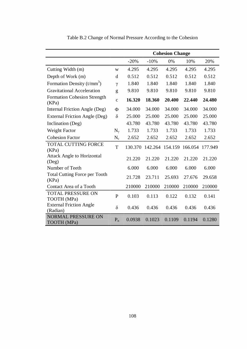
108
Table B.2 Change of Normal Pressure According to the Cohesion
Cohesion Change
-20% -10% 0% 10% 20%
Cutting Width (m) w 4.295 4.295 4.295 4.295 4.295
Depth of Work (m) d 0.512 0.512 0.512 0.512 0.512
Formation Density (t/mm3) γ 1.840 1.840 1.840 1.840 1.840
Gravitational Acceleration g 9.810 9.810 9.810 9.810 9.810
Formation Cohesion Strength
(KPa) c 16.320 18.360 20.400 22.440 24.480
Internal Friction Angle (Deg) 34.000 34.000 34.000 34.000 34.000
External Friction Angle (Deg) δ 25.000 25.000 25.000 25.000 25.000
Inclination (Deg) 43.780 43.780 43.780 43.780 43.780
Weight Factor Nγ 1.733 1.733 1.733 1.733 1.733
Cohesion Factor Nc 2.652 2.652 2.652 2.652 2.652
TOTAL CUTTING FORCE
(KPa) T 130.370 142.264 154.159 166.054 177.949
Attack Angle to Horizontal
(Deg) 21.220 21.220 21.220 21.220 21.220
Number of Teeth 6.000 6.000 6.000 6.000 6.000
Total Cutting Force per Tooth
(KPa) 21.728 23.711 25.693 27.676 29.658
Contact Area of a Tooth 210000 210000 210000 210000 210000
TOTAL PRESSURE ON
TOOTH (MPa) P 0.103 0.113 0.122 0.132 0.141
External Friction Angle
(Radian) δ 0.436 0.436 0.436 0.436 0.436
NORMAL PRESSURE ON
TOOTH (MPa) Pn 0.0938 0.1023 0.1109 0.1194 0.1280

109
Table B.3 Change of Normal Pressure According to the Internal Friction Angle
Internal Friction Angle Change
-20% -10% 0% 10% 20%
Cutting Width (m) w 4.295 4.295 4.295 4.295 4.295
Depth of Work (m) d 0.512 0.512 0.512 0.512 0.512
Formation Density (t/mm3) γ 1.840 1.840 1.840 1.840 1.840
Gravitational Acceleration g 9.810 9.810 9.810 9.810 9.810
Formation Cohesion Strength
(KPa) c 16.320 18.360 20.400 22.440 24.480
Internal Friction Angle (Deg) 27.200 30.600 34.000 37.400 40.800
External Friction Angle (Deg) δ 25.000 25.000 25.000 25.000 25.000
Inclination (Deg) 43.780 43.780 43.780 43.780 43.780
Weight Factor Nγ 1.426 1.561 1.733 1.912 2.168
Cohesion Factor Nc 2.459 2.525 2.652 2.789 2.964
TOTAL CUTTING FORCE
(KPa) T 117.220 133.670 154.159 176.485 203.620
Attack Angle to Horizontal
(Deg) 21.220 21.220 21.220 21.220 21.220
Number of Teeth 6.000 6.000 6.000 6.000 6.000
Total Cutting Force per Tooth
(KPa) 19.537 22.278 25.693 29.414 33.937
Contact Area of a Tooth 210000 210000 210000 210000 210000
TOTAL PRESSURE ON
TOOTH (MPa) P 0.093 0.106 0.122 0.140 0.162
External Friction Angle
(Radian) δ 0.436 0.436 0.436 0.436 0.436
NORMAL PRESSURE ON
TOOTH (MPa) Pn 0.0843 0.0961 0.1109 0.1269 0.1465
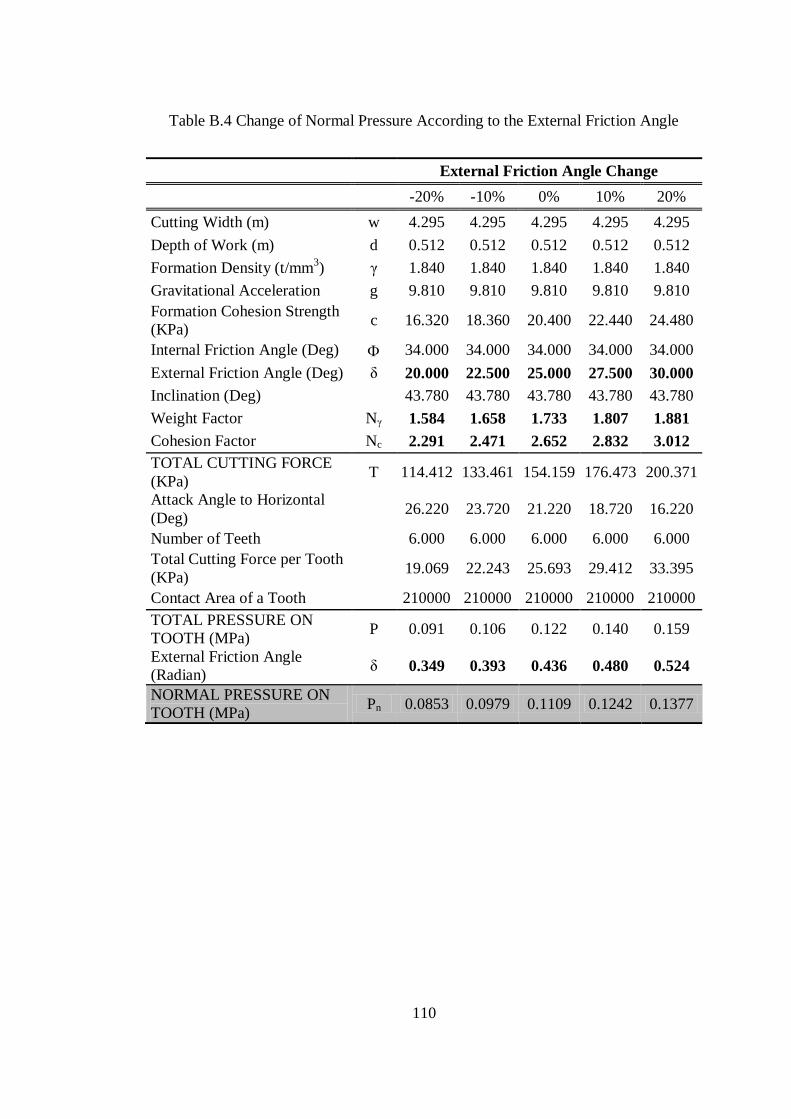
110
Table B.4 Change of Normal Pressure According to the External Friction Angle
External Friction Angle Change
-20% -10% 0% 10% 20%
Cutting Width (m) w 4.295 4.295 4.295 4.295 4.295
Depth of Work (m) d 0.512 0.512 0.512 0.512 0.512
Formation Density (t/mm3) γ 1.840 1.840 1.840 1.840 1.840
Gravitational Acceleration g 9.810 9.810 9.810 9.810 9.810
Formation Cohesion Strength
(KPa) c 16.320 18.360 20.400 22.440 24.480
Internal Friction Angle (Deg) 34.000 34.000 34.000 34.000 34.000
External Friction Angle (Deg) δ 20.000 22.500 25.000 27.500 30.000
Inclination (Deg) 43.780 43.780 43.780 43.780 43.780
Weight Factor Nγ 1.584 1.658 1.733 1.807 1.881
Cohesion Factor Nc 2.291 2.471 2.652 2.832 3.012
TOTAL CUTTING FORCE
(KPa) T 114.412 133.461 154.159 176.473 200.371
Attack Angle to Horizontal
(Deg) 26.220 23.720 21.220 18.720 16.220
Number of Teeth 6.000 6.000 6.000 6.000 6.000
Total Cutting Force per Tooth
(KPa) 19.069 22.243 25.693 29.412 33.395
Contact Area of a Tooth 210000 210000 210000 210000 210000
TOTAL PRESSURE ON
TOOTH (MPa) P 0.091 0.106 0.122 0.140 0.159
External Friction Angle
(Radian) δ 0.349 0.393 0.436 0.480 0.524
NORMAL PRESSURE ON
TOOTH (MPa) Pn 0.0853 0.0979 0.1109 0.1242 0.1377