investigation of ethanol based secondary fluids with … · investigation of ethanol based...
TRANSCRIPT

Proceedings World Geothermal Congress 2015
Melbourne, Australia, 19-25 April 2015
1
Investigation of Ethanol Based Secondary Fluids with Denaturing Agents and Other
Additives Used for Borehole Heat Exchangers
Monika Ignatowicz, José Acuña, Åke Melinder, Björn Palm
KTH Royal Institute of Technology, Department of Energy Technology, Brinellvägen 68, 100 44 Stockholm, Sweden
Keywords: secondary fluid, borehole heat exchanger, ground source heat pump, thermophysical properties, pressure drop, ethanol,
denaturing agents
ABSTRACT
Ground source heat pumps are commonly used in Sweden. The dominating method of exchanging heat with the ground is by
circulation of a secondary fluid through borehole heat exchangers inserted into energy wells. Due to the environmental reasons and
relatively good thermophysical properties, aqueous solutions of ethanol are recommended and are commonly used for the borehole
heat exchanger application in Sweden and other Nordic countries. The primary idea of using these fluids is to decrease the freezing
point of the fluid since many borehole loops in Northern Europe operate near or below the freezing point of water. The available
ethanol based commercial products consist of ethyl alcohol with up to 10% of denaturing agents without any corrosion inhibitors.
The main denaturing agents used to prevent from drinking are mixtures of isopropyl alcohol, n-butanol, acetone, methyl ethyl
ketone and methyl isobutyl ketone. These denaturing agents in commercial secondary fluids can influence the fluid’s
thermophysical properties and thereby affect the pressure drop and heat transfer in the borehole heat exchanger. These not well
defined effects of additives can cause uncertainties in the ground source heat pump design and operation. The thermophysical
properties of a few aqueous ethanol solutions are experimentally studied in this paper including a field sample, a pure mixture of
ethanol and ethanol including additives are compared with reference data. The density of 20 wt-% solution of ethanol including
additives and the field sample were higher than pure 20 wt-% ethanol sample. The additives increased the specific heat capacity by
2.3% at -10 ºC and 1% at 0 ºC. A decrement by 10.5% in the dynamic viscosity was observed. Presence of additives increased the
thermal conductivity values by around 1.5% at -8 ºC and 4.3% at +40 ºC. Some implications in terms of pressure drop and fluid to
pipe thermal resistance are observed when these properties are applied in borehole heat exchangers, as the occurrence for laminar or
turbulent varies at given temperature levels. An alternative would be to replace the denaturing agents with corrosion inhibitors to
decrease the concentration of additives, improve corrosion protection of the systems and still fulfill the market recommendations.
1. INTRODUCTION
A secondary fluid is a medium used for transporting heat as well as transferring heat between two bodies due to temperature
difference. One of the most common secondary fluids is water, which cannot be used when the operating temperature is below +3
°C due to its freezing temperature at 0 °C as mentioned by Aittomäki and Kianta (2003). However, various freezing point
depressants (antifreeze agents) can be added to water, e.g.; ethanol (ethyl alcohol), propylene glycol, ethylene glycol, chlorides,
potassium formate, potassium acetate and potassium carbonate. An extensive study about this was presented in Melinder (2007).
One application for secondary fluids that has become very popular during the last decades is Ground Source Heat Pump (GSHP)
systems. In Sweden there are about 500 000 small and 400 large GSHP systems using secondary loops, most of them in vertical
borehole loops. Swedish GSHP systems deliver approximately 15 TWh energy per year, with a total installed capacity estimated to
be about 4,6 GW as found in Antics et al. (2013). The typical set up of such a system consists of one or several borehole heat
exchangers (BHE) vertically drilled in the ground to a certain depth (normally between 120 to 300m). The most common secondary
fluid used for the borehole heat exchangers in Sweden is an aqueous solution of ethanol, and it is recommended by the Geological
Survey of Sweden (SGU) and the Swedish Environmental Protection Agency (Naturvårdsverket), SGU (2008). The available
ethanol based commercial products consist of denatured ethyl alcohol including up to 10 wt-% of denaturing agents without any
corrosion inhibitors in 95wt-% ethanol solution. The content of these denaturing agents in commercial secondary fluids will with no
doubt influence the fluid’s thermophysical properties and likely also affect the pressure drop and heat transfer in, for example,
borehole heat exchangers. The main denaturing agents (added to prevent drinking) found in these mixtures are isopropyl alcohol, n-
butanol, acetone, methyl ethyl ketone and methyl isobutyl ketone, according to European Union regulations EUR-Lex (2013). In
Sweden the most common additives found are isopropanol (isopropyl alcohol) and n-butanol. Ethyl alcohol is considered to be
environmentally friendly secondary fluid due to the fact that it occurs naturally as a fermentation product. Ethyl alcohol is expected
to biodegrade rapidly in all environments with predicted half lifetime ranging from 0.1 to 10 days, MassDEP (2011). Both
isopropanol and n-butanol can be found in nature as well and have degradation time up to 28 days, Swed Handling Chemicals
(2012).
Ethanol based secondary fluid concentration is normally not exceeding 30 wt-% (corresponding freezing point of -20.5 ºC) due to
safety regulation and flammability risks. The concentration is usually chosen to give a freezing point 8-10 K below the normal
operating temperature to avoid freezing problem, Melinder (2009). In BHEs, it is common to use about 25 wt-% concentration,
giving a freezing point of about -15 °C. This concentration is often higher than necessary. A BHE is one of many applications
where it may be relevant to have good knowledge about the thermophysical properties of the secondary fluid in order to ensure
efficient systems in terms of thermal and hydraulic performance. A small part of the total borehole resistance (i.e. inverse overall
heat transfer coefficient) per meter in a BHE is due to the convective film in the secondary fluid. In U-pipe BHEs, it is usually
desired to keep the flow within the turbulent region in order to keep a low contribution of this fluid-to-pipe thermal resistance as
described in Acuña (2013). However, the pumping power required to induce turbulence must be controlled (the pumping power is
Ignatowicz et al.
2
proportional to the pressure drop and the flow rate in the BHE pipes) so that the best heat transfer conditions are achieved in the
borehole at the lowest cost, i.e. using as little pumping energy as possible to circulate the fluid.
2. OBJECTIVES
The purpose of this paper is to investigate the effects of different additives used in the ethanol based secondary fluids by analyzing
the most important thermophysical properties (dynamic viscosity, density, thermal conductivity, specific heat capacity and freezing
point); compare these data with the reference literature values for pure ethanol solutions as well as with a field sample, including an
implication of the use of different thermophysical properties in a ground source heat pump installation.
3. METHODOLOGY
3.1 Investigation of thermophysical properties
The most important thermophysical properties of secondary fluids when evaluating performance of secondary fluids in borehole
heat exchangers are: freezing point, viscosity, thermal conductivity, specific heat capacity and density. A field sample from a BHE
installation was collected and compared with aqueous solutions of pure ethanol, ethanol solution including same concentration of
additives as the field sample, and with literature reference data retrieved from Melinder (2010). The pure ethanol sample with the
same concentration was prepared using a volumetric dilution method and its concentration was verified using Abbe refractometer
as 20 wt-% (24.47 vol-%) ethanol solution. The field sample was a denatured type of 20 wt-% solution of ethanol including 1.4-1.8
wt-% isopropanol and 0.4 wt-% n-butanol as additives. Field sample was made by diluting the “concentrate” (a concentrated
mixture of ethanol including 7-9 wt-% isopropanol and 2 wt-% n-butanol additives); to the desired concentration of 20 wt-%
solution of ethanol including 1.4-1.8 wt-% isopropanol and 0.4 wt-% n-butanol additives. In order to verify results, a control sample
of 20 wt-% ethanol including the same concentration of both additives was made in the laboratory. Since the concentration of
isopropanol additive was not exactly stated by the concentrate producer, it was decided to use the most common concentration
recommended of 8 wt-% which is at the same time an average value for the range between 7 wt-% and 9 wt-%. Control sample of
20 wt-% solution of ethanol including additives was prepared in the laboratory by first creating a similar concentrate of ethanol
including 8 wt-% isopropanol and 2 wt-% n-butanol that was later diluted to 20 wt-% solution of ethanol including additives (1.6
wt-% isopropanol and 0.4 wt-% n-butanol). Thus, the expression “20 wt-% ethanol including additives” should be understood in
this case that 20 wt-% is the total concentration of the three different alcohols: ethanol, isopropanol and n-butanol. The only
difference between the field sample and 20 wt-% ethanol sample including additives is presence of the green dye and slight
difference in concentration of isopropanol. First ice crystals were observed at -10 ºC and samples were tested down to -8 ºC only.
3.1.1 Freezing point and concentration
To measure the freezing point plastic beakers were filled with 90 ml of the tested secondary fluid and placed in specially designed
sample holder into an ultra-low temperature freezer with adjustable temperature. Thermocouples were placed in the center of each
beaker and calibrated with an accuracy of +/-0.1°C. The temperature at which the sample freezes could be detected by looking at
the temperature change profile over time. The ultra-low freezer temperature for all tests was set as -20 °C to avoid too high
temperature difference between expected freezing point and freezer inner temperature. In order to validate the method, a pure 20
wt-% ethanol solution and 20 wt-% ethanol including additives (1.6wt-% isopropanol and 0.4 wt-% n-butanol) were tested in same
conditions. All freezing tests were later compared to a reference value from Melinder (2010).
3.1.2 Density
Density measurements were performed in two different ways by using aerometers and a pycnometer. An aerometer is designed to
measure the density of a liquid at +20 °C according to ISO 17025 with accuracy of +/-0.001 g/ml. The pycnometer or specific
gravity bottle is another way to obtain accurate measurements of density. The pycnometer is a flask with a stopper that has a
capillary tube through it. The specific volume of pycnometer (25.131 cm3) was determined according to DIN ISO 3507 with
tolerance of +/-0,01cm3. The pycnometer uses a working liquid with well-known density, such as distilled water, to define the
volume. By knowing the volume and measuring mass of empty as well as full pycnometer with Mettler Toledo high accuracy
analytical balance (accuracy of +/-0.0001g), it is possible to determine the density of secondary fluid including additives at +20 °C.
Later, all results are fitted to a function to extrapolate values in the desired range between -10 ºC to +40 ºC.
3.1.3 Dynamic viscosity
A Brookfield rotational viscometer DV-II Pro with special low viscosity adapter (UL-adapter) with temperature controlled water-
ethylene glycol jacket was used to perform measurements in the temperature range –8 °C to +40 °C. The temperature accuracy for
the viscometer is defined as +/-1°C and Brookfield refrigeration unit as +/-0.2 °C. The operation principle of the rotational
viscometer is to drive a spindle (which is immersed in the test fluid) through a calibrated spring. The viscous drag of the secondary
fluid against the spindle is measured by the spring deflection. The measurement range of a rotational viscometer is determined by
the rotational speed of the spindle, the size and shape of the spindle, the container the spindle is rotating in, and the full scale torque
of the calibrated spring. All viscosity measurements in temperature range between -8 °C and +40 °C for different ethanol based
secondary fluids are done using UL-adapter and the same spindle to reduce the uncertainty in measurements.
3.1.4 Thermal conductivity
Thermal conductivity measurements were done using Transient Plane Source (TPS) method by means of a Hot Disk Thermal
Constants Analyzer TPS-2500. The method is based on the use of a heated plane sensor. The Hot Disk sensor consists of an
electrically conducting pattern in the shape of a double spiral, which has been etched out of a thin metal (Nickel) foil. This spiral is
sandwiched between two thin sheets of an insulating material (Kapton). When performing a thermal conductivity measurement, the
plane Kapton sensor is fitted between two pieces of the sample holder filled with liquid. By passing an electrical current high
enough to increase the temperature of the sensor between a fraction of a degree up to several degrees, and at the same time
recording the resistance (temperature) increase as a function of time, the sensor is used both as a heat source and as a dynamic
temperature sensor. The typical liquid sample size is 10 ml and 25mm inner diameter of sample holder. It is important that the size

Ignatowicz et al.
3
of the sample surfaces is appreciably larger than the diameter of the sensor, thus Kapton sensor 7577 with radius 2,001 mm was
chosen.
3.1.5 Specific heat capacity
The specific heat capacity was measured using the Differential Scanning Calorimetry (DSC) method. It is a thermo analytical
technique in which the difference in the amount of heat required to increase the temperature of sample and reference is measured.
Both sample and reference are maintained at the same temperature throughout the experiment. Generally, the temperature program
for a DSC analysis is designed such that the sample holder temperature increases linearly as a function of time. The reference
sample should have a well-defined heat capacity over the range of temperatures to be scanned. To perform tests, a microDSC evo7
from Setaram Instrumentation was used. The tests were performed in Cp continuous mode with heating scanning rate of 0.05 K/min
in temperature range between -15 °C and +40 °C. The tested sample volume was 580 μl and the tests were repeated three times.
3.2 Some implications for a borehole heat exchanger
The variations in thermophysical properties of the secondary fluids tested in this paper according to the methods explained in
section 3.1 are put in perspective in terms of calculated secondary fluid-to- pipe thermal resistance and pressure drop in a U-pipe
BHE of type PE 40x2.4 mm and with depth of 140 m. The pressure drop ∆P in the pipes occurs mainly due to friction and it is
estimated assuming fully developed flow according to eq. (1)
D
LwfP
2
2
(1)
The calculated pressure drop does not include the losses in the U-bend of the BHE. The estimation of the friction factor f depends
on whether the flow is laminar or turbulent. In this paper, this is solved for laminar flow (for Re ≤ 2300) with eq. (2) and for
turbulent flow (for Re ≥ 2300) with the correlation suggested by Gnielinski (1976), eq. (3)
Re
64f (2)
264,1Reln79,0
1
f
(3)
where the Reynolds number is calculated as stated in eq. (4)
DwRe (4)
The internal convection resistance at a given temperature inside the U-pipe shanks can be estimated as a function of an average
internal heat transfer coefficient, h, as expressed in eq. 5.
Dh
R pf
1 (5)
where h is obtained using eq. (6)
D
kNuh
(6)
and the Nusselt number is calculated using the correlation for the turbulent case given by Gnielinski, eq. (7)
𝑁𝑢 =(f 8⁄ )(ReD − 1000)Pr
1 + 12.7(f 8⁄ )1 2⁄ (Pr2 3⁄ − 1)
(7)
For laminar flow (assuming constant heat flux and fully developed conditions), Nu = 4.36.
4. RESULTS
4.1 Thermophysical properties
Table 1 presents the results of the freezing point test for all samples. The freezing point of 20 wt-% ethanol according to data from
Melinder (2010) is -10.92 °C. Experiments showed lower freezing points for three different samples tested in same conditions. The
difference in the freezing point for the reference fluid (Melinder 2010) and pure 20 wt-% ethanol solutions could be related to the
experimental conditions. A subcooling effect of 3-4 K was observed for all three tested samples. Moreover, very similar freezing
points were obtained for both the field sample and corresponding 20 wt-% ethanol including additives, which confirmed the
concentration of the field sample with information stated by the ethanol producer.
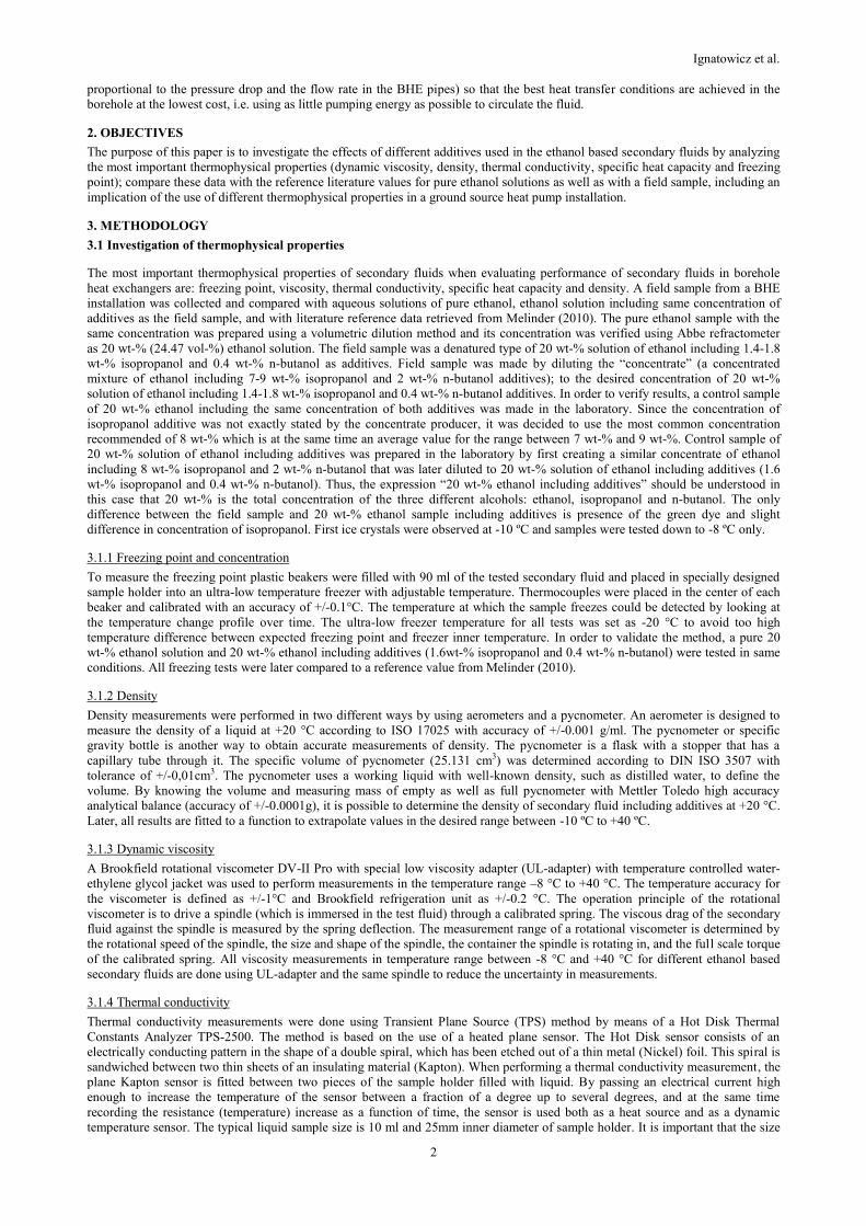
Figure 1, presents the dynamic viscosity for pure 20 wt-% ethanol; 20 wt-% ethanol including additives and field sample. As seen,
the pure ethanol 20 wt-% results were slightly higher than the reference values from Melinder (2010). Moreover, the field sample
Ignatowicz et al.
4
and 20 wt-% ethanol including additives had about 10 % lower dynamic viscosity than the pure 20 wt-% ethanol. Results indicate
that the presence of additives can lead to lower dynamic viscosity. Thus, isopropanol and n-butanol additives decreased the
dynamic viscosity. This can have practical consequences in terms of pressure drop as will be shown for a U-pipe BHE later in this
article.
Figure 1: Dynamic viscosity results.
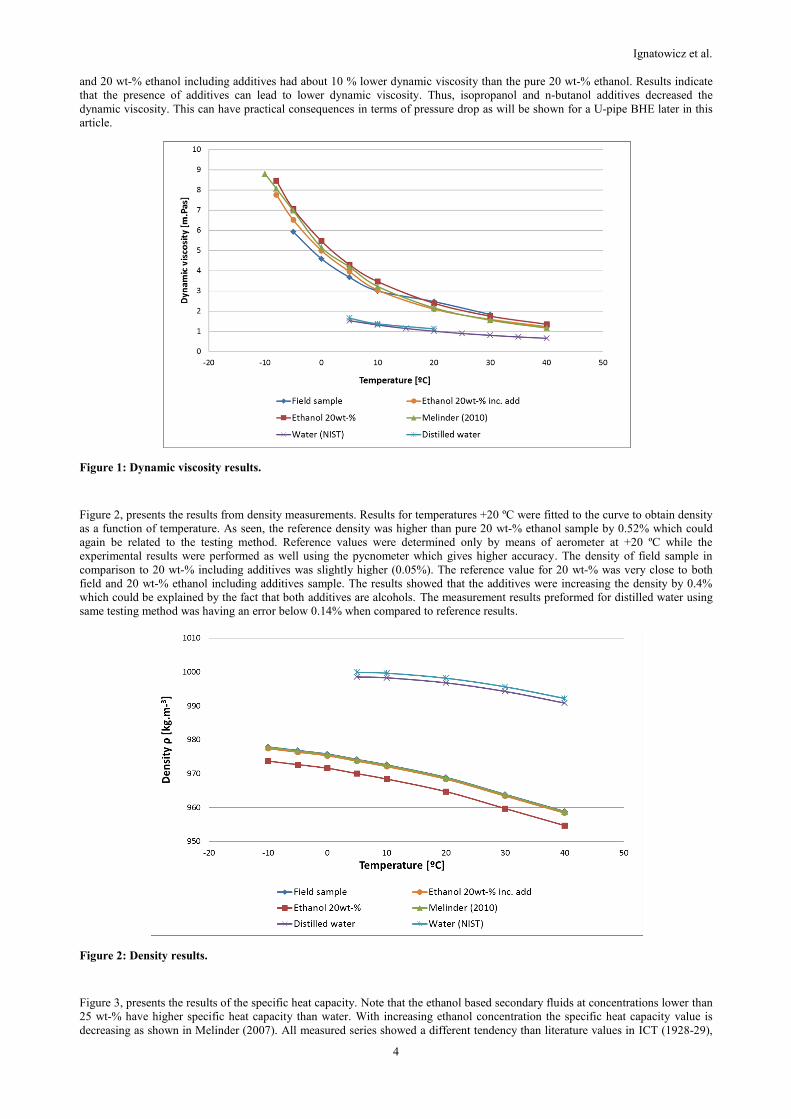
Figure 2, presents the results from density measurements. Results for temperatures +20 ºC were fitted to the curve to obtain density
as a function of temperature. As seen, the reference density was higher than pure 20 wt-% ethanol sample by 0.52% which could
again be related to the testing method. Reference values were determined only by means of aerometer at +20 ºC while the
experimental results were performed as well using the pycnometer which gives higher accuracy. The density of field sample in
comparison to 20 wt-% including additives was slightly higher (0.05%). The reference value for 20 wt-% was very close to both
field and 20 wt-% ethanol including additives sample. The results showed that the additives were increasing the density by 0.4%
which could be explained by the fact that both additives are alcohols. The measurement results preformed for distilled water using
same testing method was having an error below 0.14% when compared to reference results.
Figure 2: Density results.
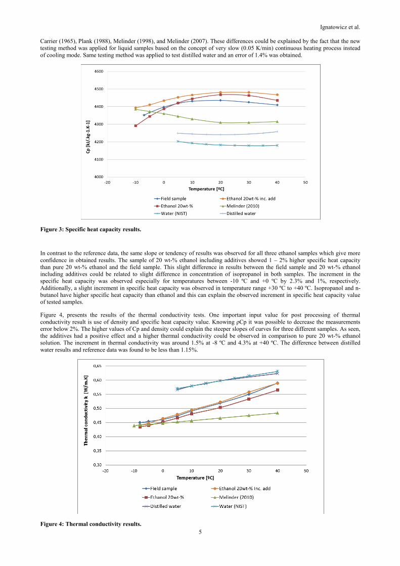
Figure 3, presents the results of the specific heat capacity. Note that the ethanol based secondary fluids at concentrations lower than
25 wt-% have higher specific heat capacity than water. With increasing ethanol concentration the specific heat capacity value is
decreasing as shown in Melinder (2007). All measured series showed a different tendency than literature values in ICT (1928-29),
Ignatowicz et al.
5
Carrier (1965), Plank (1988), Melinder (1998), and Melinder (2007). These differences could be explained by the fact that the new
testing method was applied for liquid samples based on the concept of very slow (0.05 K/min) continuous heating process instead
of cooling mode. Same testing method was applied to test distilled water and an error of 1.4% was obtained.
Figure 3: Specific heat capacity results.
In contrast to the reference data, the same slope or tendency of results was observed for all three ethanol samples which give more
confidence in obtained results. The sample of 20 wt-% ethanol including additives showed 1 – 2% higher specific heat capacity
than pure 20 wt-% ethanol and the field sample. This slight difference in results between the field sample and 20 wt-% ethanol
including additives could be related to slight difference in concentration of isopropanol in both samples. The increment in the
specific heat capacity was observed especially for temperatures between -10 ºC and +0 ºC by 2.3% and 1%, respectively.
Additionally, a slight increment in specific heat capacity was observed in temperature range +30 ºC to +40 ºC. Isopropanol and n-
butanol have higher specific heat capacity than ethanol and this can explain the observed increment in specific heat capacity value
of tested samples.
Figure 4, presents the results of the thermal conductivity tests. One important input value for post processing of thermal
conductivity result is use of density and specific heat capacity value. Knowing ρCp it was possible to decrease the measurements
error below 2%. The higher values of Cp and density could explain the steeper slopes of curves for three different samples. As seen,
the additives had a positive effect and a higher thermal conductivity could be observed in comparison to pure 20 wt-% ethanol
solution. The increment in thermal conductivity was around 1.5% at -8 ºC and 4.3% at +40 ºC. The difference between distilled
water results and reference data was found to be less than 1.15%.
Figure 4: Thermal conductivity results.

Ignatowicz et al.
6
4.2 Pressure drop and fluid to pipe thermal resistance in a U-pipe borehole heat exchanger
The pressure drop and the fluid to pipe thermal resistances in a U-pipe BHE have been calculated for the ethanol mixtures at three
different volumetric flow rates (typical flow rates in BHE installations today), using the thermophysical properties presented in
section 4.1 for three temperatures within the typical operating range of BHEs in northern Europe during heat extraction mode: +5, 0
and -5 °C. The idea is to identify the implications of using some of these properties in borehole heat exchanger design for typical
flow conditions.
A compulsory first step before carrying out the calculations is the determination of the Reynolds number, which decides whether
the flow regime for each case is laminar, transitional or turbulent, and indicates the correlations that should be used in the design
process. The result of this calculation, introducing the laboratory density and viscosity measurements in equation (4), is presented
in Figure 5. An axis line has been on purpose drawn at Re = 2300 in order to delimit the theoretical transition between laminar and
turbulent flow.
Figure 5: Reynolds number for different fluid properties at different flow rates in a PE40X2.4mm U-pipe BHE.
For all fluids, Reynolds number decreases with decreasing temperature level, related to the shape of the density and viscosity
curves shown in the previous section of this paper. The properties of the field sample and the ethanol solution including additives
give the highest Reynolds number when compared to pure ethanol and to the reference data. This is valid for all flows and
temperature levels. In some cases when the flow is 0.2 and 0.3 l/s, the properties of the field sample results in turbulent flow while
the pure mixture and the values from Melinder (2010) indicate laminar flow, for example.
As expected, the Reynolds number increases with increasing flow rate for a given temperature, being laminar or turbulent
depending on the fluid properties. The effect of more viscous flows at lower temperatures for a given fluid sample becomes clear.
At the lowest flow rate, the regime is laminar in all cases. At 0.3 l/s the regime is strictly dependent on the viscosity values while at
the highest flow rate (0.4 l/s); the flow is almost always turbulent. It is suspected, however, that good heat transfer conditions
cannot be guaranteed at such flow rates since it is known that the Reynolds number even varies from inlet and outlet along the U-
pipe.
The flow regime has implications for a U-pipe BHE in terms of pressure drop and fluid-to-pipe thermal resistance, Rf-p. The
pressure drop and Rf-p calculated for the conditions from Figure 5 are shown in Figure 6 and Figure 7, respectively. These results
were obtained using the approach presented in section 3.2. The pressure drop indicates that, in a few cases, the result falls outside
what could be intuitively estimated, although it is normal to expect that ΔP increases with decreasing temperature level as the
viscosity and density become higher.
The internal fluid-to-pipe thermal resistance shown in Figure 7 shows that the convective layer inside the pipes can significantly
affect the resistance if the flow is laminar, as expected. Laminar flow conditions become harmful and the highest flow is certainly
preferred in U-pipe BHEs. Most of the conditions with the low and medium flow rates, independently of the fluid properties are
unfavorable for heat transfer and for a proper thermal performance of the U-pipe. Even at the higher flow rate (0.4 l/s), laminar
conditions are obtained at the lowest temperature levels. It seems, though, that the characteristics of the field sample representing
the commercial products are more favorable than pure ethanol solutions, implying that installations may probably perform slightly

Ignatowicz et al.
7
better than expected. It can be seen that, within each pipe, the resistance is normally lower than 0.02 Km/W for turbulent flow. If
the pipes are symmetrically placed inside the borehole, the contribution of the fluid to pipe resistance to the total borehole
resistance is, in this case, no more than about 0.01 Km/W. This number can be put in perspective as compared to the total local
borehole resistance in a groundwater-filled borehole (which also includes the contribution the pipe properties and thickness, and the
convection outside the pipes), typically ranging from 0.06 to 0.09 Km/W, see Acuña (2013), i.e. Rf-p is a small fraction of the total
resistance. On the other hand, Rf-p would have a dominant weight at laminar conditions, as interpreted from Figure 7.
Figure 6: Pressure drop for different fluid properties at different flow rates.
Figure 7: Fluid to pipe thermal resistance for different fluid properties at different flow rates.

Ignatowicz et al.
8
5. CONCLUSIONS
Summing up, isopropanol and n-butanol did not have a significant effect on the freezing point despite the chemical nature of both
additives. Results showed that presence of additives was not affecting so much the density (less than 0.4%) due to the similarity in
chemical structure of alcohols used as the denaturing agents. Dynamic viscosity results showed that both samples containing
isopropanol and n-butanol additives were having up to 10% lower dynamic viscosity than pure 20 wt-% ethanol. Specific heat
capacity results showed a different tendency for 20 wt-% ethanol comparing to previously reported results. Sample of 20 wt-%
ethanol including additives showed higher specific heat capacity than pure 20 wt-% ethanol and field sample. The increment in the
specific heat capacity was observed especially for temperatures between -10 ºC and +10 ºC which are the common operating
temperatures for secondary fluid used in borehole heat exchangers. A slight increment in specific heat capacity was observed in
temperature range +30 ºC to +40 ºC as well. Isopropanol and n-butanol have higher specific heat capacity than ethanol and this fact
can explain the increment of specific heat capacity value. Additionally, the additives present in field sample and 20 wt-% ethanol
were having positive effect and higher thermal conductivity could be observed in comparison to pure 20 wt-% ethanol solution. The
increment in thermal conductivity was around 1.5% at -10 ºC and 4.4% at +40 ºC.
In a U-pipe borehole heat exchanger, laminar conditions and low temperature levels should be avoided. The thermophysical
properties must be carefully chosen in order to avoid errors in the design when the operation conditions are close to the transition
between laminar and turbulent flow.
6. NOMENCLATURE
BHE Borehole Heat Exchanger
Cp Specific heat capacity [kJkg-1K-1]
D Hydraulic diameter [m]
f Friction factor [-]
h Internal heat transfer coefficient [Wm-2K-1]
k Thermal conductivity [Wm-1K-1]
L Pipe length [m]
Nu Nusselt number [-]
PE Polyethylene
Pr Prandtl number [-]
Re Reynolds number [-]
Rf_p Fluid to pipe wall resistance [mKW-1]
TPS Transient Plane Source
w Velocity [m.s-1]
wt-% Weight concentration [-]
ΔP Pressure drop [Pa]
μ Dynamic viscosity [mPas]
ρ Density [kgm-3]
ACKNOWLEGMENT
The Swedish Energy Agency, the Effsys+ project, KYS Kylbranschens Samarbetsstiftelse and all our industrial partners are greatly
acknowledged for financing this project.
REFERENCES
Acuña J.: Distributed thermal response tests: New insights on U-pipe and Coaxial heat exchangers in groundwater-filled boreholes,
Doctoral thesis, KTH Royal Institute of Technology, Stockholm, Sweden, ISBN 978-91-7501-626-9, (2013).
Aittomäki A., Kianta J.: Indirect Refrigeration Systems – Design Guide Book, Tampere University of Technology, Tampere,
Finland, ISBN 952-15-1023-4, (2003)
Antics M., Bertani R., Sanner B.: Summary of EGC 2013 Country update reports on geothermal energy in Europe, Proceedings,
Pisa, Italy, (2013).
Carrier: Handbook of Air Conditioning System Design, Carrier Corporation, Carrier Air Conditioning Company, McGraw-Hill,
ISBN 007010090X, (1965).

Ignatowicz et al.
9
EUR-Lex.: COMMISSION IMPLEMENTING REGULATION (EU) No 162/2013 of 21 February 2013 amending the Annex to
Regulation (EC) No 3199/93 on the mutual recognition of procedures for the complete denaturing of alcohol for the purposes
of exemption from excise duty”, Official Journal of European Union (2013)
ICT: International Critical Tables of Numerical Data, Physics, Chemistry and Technology, (1928-29).
MassDEP: Massachusetts Department of Environmental Protection, Large Volume Ethanol Spills – Environmental Impacts and
Response Options Report, July 2011, Shaw’s Environmental and Infrastructure Group, (2011).
Melinder Å.: Thermophysical properties of liquid secondary refrigerants – A critical review on literature references and laboratory
measurements, Engineering Licentiate thesis, Royal Institute of Technology, KTH, Stockholm, Sweden, ISSN 1102-0245,
(1998).
Melinder Å.: Thermophysical Properties of Aqueous Solutions Used as Secondary Working Fluids, Doctoral thesis, Royal Institute
of Technology, KTH, Stockholm, Sweden, ISBN 978-91-7178-707-1, (2007).
Melinder Å.: Handbok om indirekta kyl- och värmepumpsystem, Kullavik, Svenska Kyltekniska Föreningen, KTF, ISBN 978-91-
633-5720-6, (2009).
Melinder Å.: Properties of Secondary Working Fluids for Indirect Systems, Paris, International Institute of Refrigeration, IIR, ISBN
978-2-913149-76-2, (2010).
Plank R.: Handbuch der Kältetechnik, VI/B, ISBN 978-3-642-82522-4, (1988).
SGU: NORMBRUNN–07, Att borra brunn för energi och vatten – en vägledning, Normförfarande vid utförande av vatten- och
energibrunnar, Sveriges Geologiska Undersökning, (2008).
Swed Handling Chemicals: E-THERM KBS BIO as secondary fluid, Materials safety data sheet (MSDS), Swed Handling
Chemicals AB, available at http://www.swedhandling.com/pdf/E-thermKBSBio.pdf, accessed on: 2014-09-25, (2012).