introductory scientific paper about knowledge-based expert systems
TRANSCRIPT

EXPERT SYSTEMS1
Peter Lucas, Institute for Computing and Information Sciences,Radboud University, Nijmegen, The Netherlands,E-mail: [email protected]
KeywordsExpert Systems, Knowledge-based Systems, Knowledge System, Knowledge Engineering,Knowledge Management, Influence Diagrams, Abduction, Consistency-based Reasoning, De-duction, Horn Clauses, Inheritance, Bayesian Belief Networks, Problem Solving, InferenceEngine, Automated Reasoning, Rules
Contents
Glossary 2
Summary 6
1 Introduction 61.1 Definition of the Field . . . . . . . . . . . . . . . . . . . . . . . . . . . . . . . 61.2 Origin and Evolution . . . . . . . . . . . . . . . . . . . . . . . . . . . . . . . . 7
2 Expert System Principles 72.1 Expert System Architecture . . . . . . . . . . . . . . . . . . . . . . . . . . . . 82.2 Problem-solving Methods . . . . . . . . . . . . . . . . . . . . . . . . . . . . . 9
3 Knowledge Representation and Inference 93.1 Logic Representation and Reasoning . . . . . . . . . . . . . . . . . . . . . . . 10
3.1.1 Horn-clause Logic . . . . . . . . . . . . . . . . . . . . . . . . . . . . . 103.1.2 Objects, Attributes and Values . . . . . . . . . . . . . . . . . . . . . . 12
3.2 Diagnostic Problem Solving . . . . . . . . . . . . . . . . . . . . . . . . . . . . 133.2.1 Deductive Diagnosis . . . . . . . . . . . . . . . . . . . . . . . . . . . . 133.2.2 Abductive Diagnosis . . . . . . . . . . . . . . . . . . . . . . . . . . . . 143.2.3 Consistency-based Diagnosis . . . . . . . . . . . . . . . . . . . . . . . 15
3.3 Configuring and Design . . . . . . . . . . . . . . . . . . . . . . . . . . . . . . 173.4 Uncertainty . . . . . . . . . . . . . . . . . . . . . . . . . . . . . . . . . . . . . 193.5 Decision Making . . . . . . . . . . . . . . . . . . . . . . . . . . . . . . . . . . 22
4 Knowledge Engineering 23
5 Conclusions 25
1Published in the Encyclopedia of Life Support Systems of UNESCO.
1
Glossary
Abduction: Type of reasoning with causal knowledge in which observations are explainedin terms of represented cause-effect relationships.
Attribute: Feature of an object or a thing; a description of an object or a thing is obtainedby inspecting its attributes with its associated values, possibly extended by those ob-tained by inheritance.
Bayesian belief network: Representation of a joint probability distribution Pr(X1, . . . , Xn)defined on random variables Xi, for i = 1, . . . , n, as nodes in a directed acyclic graph.The joint probability distribution is defined in terms of a set of (conditional) probabilitydistributions Pr(Xi | π(Xi)), where π(Xi) corresponds to the set of parent nodes of thenode corresponding to the variable Xi. Formally, it holds that:
Pr(X1, . . . , Xn) =n∏
i=1
Pr(Xi | π(Xi))
By setting variables to particular values, representing in this way the effect of observingevidence E, an updated probability distribution can be computed. If PrE is the updatedprobability distribution, then PrE(Vi) gives the updated probability distribution, takingthe effect of E into account. It holds that PrE(Vi) = Pr(Vi | E), i.e. the originalprobability distribution with respect to Vi, conditioned on the evidence E.
Clause: Logical formula of the form L1 ∨ L2 ∨ · · · ∨ Ln, where Li is either equal to anatomic formula Ai or its negation ¬Ai. Atomic formulas may contain terms, includingvariables; the variables then have the meaning of universally quantified variables.
Completeness: Any formula ϕ which follows logically from another formula ψ, will also bederived using logical (syntactical) inference rules; formally, if ψ � ϕ then ψ ` ϕ. Notethat if a logic is sound (see there) and complete, one can use either the notation ψ � ϕ
or ψ ` ϕ, as these are then equivalent, although the meanings of these two notions isstill different.
Conditional independence: Two random variables A and B are called conditionallyindependent given a third random variable C if it holds that Pr(A | B,C) = Pr(A | C),or equivalently, if it holds that Pr(B | A,C) = Pr(B | C), where Pr is a probabilitydistribution. In words: any uncertain knowledge about B given that we already knowC does not affect our knowledge about A, and any uncertain knowledge about A giventhat we already know C does not affect our knowledge about B. See also the item‘independence’.
Consistency: a logical formula ϕ is called consistent when none of the formulas whichlogically follow from it contradict; formally: ϕ 0 ⊥, or equally ϕ 2 ⊥ if the logic issound and complete (see there).
Decision strategy: Optimal sequence of decisions of actions, determined by taking boththe uncertainty of observations and outcome of actions into account, in addition to costsof the observations, outcomes, decisions or actions.
2
Decision theory: Mathematical theory of the process of making rational choices underconditions of uncertainty.
Deduction: procedure consisting of the application of logical, syntactical inference rules tological formulas, which, when they are applicable, yield new formulas. Formal notation:if I stands for the collection of inference rules used, then the deduction of formula ϕfrom ψ is denoted by ψ `I ϕ. This may involve several inference steps, and differentinference rules. If the used collection of inference rules I is clear from the context, `I
is usually written as `.
Expert system: Information system that incorporates significant portions of human knowl-edge, often of experts in a particular domain, normally represented in a separate partof the system, called a knowledge base (see there). Also called knowledge-based systemor knowledge system.
Expert-system shell: Computer program which when supplied with a particular knowl-edge base will yield an expert system. The minimum capability of an expert-systemshell is reasoning or inference with the knowledge within the knowledge base, producingconclusions based on entered findings or facts.
Expert-system builder tool: Computer program that is used in building the knowledgebase of an expert system.
Explanation facility: Component of an expert system that is used to explain the reasoningprocess that gave rise to certain conclusions or questions to the user.
Frame: Synonymous with object.
Heuristic: Particular trick, often based on deep knowledge of a domain, which helps inachieving particular goals, such as finding the solution of a particular problem, whichotherwise would not have found at all or not in reasonable time.
Horn clause: Clause that contains at most one positive literal. Different name are linkedto Horn clauses of different forms; Horn clauses of the form A1∧· · ·∧An → B are calledrules, those of the form A1 ∧ · · · ∧ An → ⊥ are called queries, and those of the form→ B are called facts.
Inconsistency: Deduction of a contradiction between formulas deducible from a formulaψ; formally: ψ ` ⊥, or equally, for a sound and complete logic, ψ � ⊥
Independence: Two random variables A and B are called (unconditionally) independentif it holds that Pr(A | B) = Pr(A) (in words: knowing anything about B does not affectour knowledge about A), or equally, if Pr(B | A) = Pr(B), where Pr is a probabilitydistribution. See also ‘conditional independence’.
Inference: The process of deriving knowledge from given knowledge. If this knowledge isrepresented in the form of standard logic, then this term is synonymous with deduction.
Inference engine: Inference algorithm, or computer implementation of it in a programminglanguage, that allows carrying out inference steps to derive knowledge from knowledgeautomatically.
3

Influence diagram: Graph-based representation closely related to a Bayesian belief net-work, but which contains in addition to chance nodes, also decision nodes, modelingmaking decisions, and a utility node, modeling a utility function. Solving a influencediagram amounts to finding an optimal decision strategy, i.e. the utility function is be-ing optimized, taking into account the probabilistic and utility information representedin an influence diagram.
Inheritance: An object O with attributes a1, . . . , an with values c1, . . . , cn, which is knownto be a subobject of (less general than) object O ′, can be represented in first-orderpredicate logic as follows:
∀x(O(x) → (O′(x) ∧ a1(x) = c1 ∧ · · · ∧ an(x) = cn))
Similarly, if object O′ is known to be the most generic object in a domain with attributesb1, . . . , bm, this can be represented as follows:
∀x(O′(x) → (b1(x) = d1 ∧ · · · ∧ bm(x) = dn))
If these formulas are denoted by KB (knowledge base), and it is known that i is aninstance of O, then obviously:
(KB ∧O(i)) � (O′(i) ∧ b1(i) = d1 ∧ · · · ∧ bm(i) = dn ∧ a1(i) = c1 ∧ · · · ∧ an(i) = cn)
Knowledge base: Store of knowledge of a domain, specified in a knowledge-representationformalism, and used to handle specific problems in a problem domain, such diagnosingdisease, predicting weather or developments in the financial markets, using an expert-system shell.
Knowledge-based system: Synonymous with expert system. Some people make a distinc-tion between expert systems, which they see as systems that contain expert knowledge,whereas they see knowledge-based systems as systems that may contain any sort ofknowledge. As there are no hard criteria to judge whether knowledge is expert knowl-edge or not, this distinction is not very useful, and is therefore not made here.
Knowledge engineering: Process of developing an expert system.
Knowledge-representation formalism: Formal language that can be used to representknowledge. A typical example of a knowledge-representation formalism is predicatelogic. Also programming languages can be seen as knowledge-representation languages,although may of those languages have not been designed to represent every-day hu-man knowledge well, but rather as language which allow for representing specializedknowledge of how to control a machine.
Marginal probability distribution: If Pr(V1, . . . , Vn) is a joint probability distributiondefined on the variables Vi, for i = 1, . . . , n, then a probability distribution for anyproper subset of these variables is called a marginal probability distribution. It holds(for discrete probability distributions) that:
Pr(V1, . . . , Vn−1) =∑
Vn
Pr(V1, . . . , Vn)
4

i.e. by summation over the domain of Vn. This marginalization rule can be appliedrecursively to compute any marginal probability distribution from the original jointprobability distribution.
Object: In the context of expert systems, an object is usually understood to be a structuredattribute description of a thing. Often special-purpose languages are used to representobjects, but from a semantic point of view, objects in many different languages forobjects can be understood in terms of Horn-clause logic. This meaning is differentfrom that in object-oriented programming, where an object is an active process that isnormally able to communicate by exchanging messages with other objects. However,objects are specified using languages closely related to those used in expert systems.Hence, the distinction is not always clear, in particular when the capabilities of ob-jects within expert systems have been extended into the direction of object-orientedprogramming languages.
Ontology: Description of the objects in domain, usually with the purpose of precisely de-scribing the terminology in a domain. There is some relationship with a frame taxonomy,but ontologies are normally understood in a less formal way.
Reasoning: See inference.
Resolution: Special logical inference rule that can be used to derive new clauses from twogiven clauses. Given two clauses ϕ ≡ ψ ∨ P and ϑ ≡ κ ∨ ¬P , where ψ and κ are againclauses, then the resolution rule R derives the clause ψ ∨ κ, formally ϕ ∧ ϑ `R ψ ∨ κ.This simple inference rule is both sound and complete for deducing inconsistency (calledrefutation completeness), except when it is used with clauses in predicate logic, whereit has to handle the situation where it can derive clause containing similar literals, onlydiffering with respect their the universally quantified variables, such as P (x) ∨ P (y).Such a clause can be collapsed, by an operation called factoring. If this yields P (x),resolution will be complete. Thus, resolution plus factoring is sound and refutationcomplete.
Soundness: Notion opposite in meaning to that of ‘completeness’. If a collection of inferencerules is sound, it is unable to derive anything from a logical formula ϕ if that formuladoes not logically follow from that formula. Formally, if ϕ ` ψ than ϕ � ψ.
Trace facility: Component of an expert-system shell that allows following and inspectingthe inference process.
Utility: Function value of a utility function.
Utility function: If DVirepresents the domain of a variable Vi, for i = 1, . . . , n, then a
utility function is defined as a mapping u : DV1×· · ·×DVn→ R, where u(v1, . . . , vn) = c,
with c ∈ R, has the informal meaning of a cost or benefit associated with a particularcombination of values of variables.
5
Summary
Expert systems, also called knowledge-based systems or knowledge systems, are computersystems characterized by the fact that an explicit distinction is made between a part in whichknowledge of a problem domain is represented, and a part which manipulates that knowledgeto reason about or solve an actual problem using problem data. Both the type of knowledgeused in solving the problem and the nature of the problem-solving methods used determinewhich problems can be solved. The knowledge represented in a knowledge base is formalin nature, and is the result of modeling essential features of the domain for the problemat hand. The incorporated knowledge may be acquired from domain experts, literature ordatasets. Designing an expert system usually involves using methodologies for knowledgeacquisition, modeling and evaluation.
1 Introduction
In this section, the field of expert systems is introduced and defined. Furthermore, two earlyexamples of expert systems are discussed.
1.1 Definition of the Field
The phrase knowledge-based system, or knowledge system, is generally employed to denoteinformation systems in which some symbolic representation of human knowledge of a domainis applied, usually in a way resembling human reasoning, to solve actual problems in thedomain. Examples of problem domains include trouble shooting of equipment, medical di-agnosis, financial advice, product design and so on. As this knowledge is often derived fromexperts in a particular field, and early knowledge-based systems were actually developed inclose collaboration with experts, the term expert system was the term used in the early daysto refer to these systems. Knowledge, however, can also be extracted from literature, or froma datasets by using machine-learning methods. Moreover, not all domains of specific expertsystems may be viewed as specialists’ fields. As a consequence, some people prefer to makea distinction between expert systems and knowledge-based systems – in their view the latterare more general than the former as the former should always concern a specialist’s field. Inthis article such a distinction will not be made as the techniques used in knowledge-basedsystems and the ones used in building expert systems are identical. Hence, the terms ‘expertsystem’ and ‘knowledge-based system’ will be used interchangingly.
Present generation expert systems are capable of dealing with restricted problem domains.Gathering, maintaining and updating the incorporated knowledge taking into account itsassociated context, such as working environment, organization and field of expertise belongsto an area referred to as knowledge management. The art of developing an expert system iscalled knowledge engineering, when there is emphasis on the pragmatic engineering aspects,or knowledge modeling, when development of domain models is emphasized. The latter isstrictly speaking part of the former. The process of collecting and analyzing knowledge in aproblem domain is called knowledge acquisition, or knowledge elicitation when the knowledgeis gathered from interviews with experts, normally using interview techniques as developedby psychologists.
6
1.2 Origin and Evolution
One of the first systems with which the phrase expert system has been associated, is Heuristic
DENDRAL. The DENDRAL project commenced in 1965 at Stanford University. The systemwas developed by J. Lederberg, an organic chemist (and Nobel prize winner in chemistry), inconjunction with E.A. Feigenbaum and B.G. Buchanan, both well-known research scientistsin artificial intelligence at the time. The Heuristic DENDRAL system offered assistance inthe field of organic chemistry in determining the structural formula of a chemical compoundthat has been isolated from a given sample. In determining a structural formula, informationconcerning the chemical formula, such as C4H9OH for butanol, and the source the compoundhas been taken from, is used as well as information that has been obtained by subjecting thecompound to physical, chemical and spectrometric tests. The original DENDRAL algorithmwas developed by J. Lederberg for generating all possible isomers of a chemical compound.Heuristic DENDRAL contains a subsystem, the so-called Structure Generator, which imple-ments the DENDRAL algorithm, but in addition incorporates various heuristic constraints onpossible structures, thus reducing the number of alternatives to be considered by the remain-der of the system. Heuristic DENDRAL helps in interpreting the patterns in a spectrogram.It contains a considerable amount of chemical knowledge to do so. To this end, anothersubsystem of Heuristic DENDRAL, called the Predictor, suggests expected mass spectro-grams for each molecular structure generated by the Structure Generator. Each expectedmass spectrogram is then tested against the mass spectrogram observed using some measureof similarity for comparison; this has been implemented in the last part of the system, theEvaluation Function. Usually, more than one molecular structure matches the pattern foundin the spectrogram. Therefore, the system usually produces more than one answer, orderedby the amount of evidence favoring them.
The best-known expert system of this early period of the field is MYCIN, a system de-veloped by E.H. Shortliffe when at Stanford University at the end of the 1970s. The MYCINsystem was capable of assisting physicians in the diagnosis and treatment of some infectiousdiseases, in particular meningitis and bacterial septicemia. When a patient shows the signsof such a disease, a culture of blood and urine is made in order to determine which bacteriumspecies caused the infection. Usually, it takes 24 to 48 hours before the laboratory resultsare known. Often, however, the physician cannot wait that long before starting treatment,since otherwise the disease will progress and actually cause the death of the patient. MYCINgives an interim indication of the organisms most likely responsible for the patient’s diseaseon the basis of the (possibly incomplete and inexact) patient data available to the system.Given this indication, MYCIN advises on the administration of appropriate drugs to controlthe infection. Again, the system was only capable of doing so by drawing upon a considerablebody of formalized expert knowledge in infectious disease. The MYCIN system clearly left itsmark on the expert systems that have been developed since. Even today, this expert systemand its derivatives are a source of inspiration for expert system researchers.
2 Expert System Principles
As an expert system is a software system, the structure of expert systems can be describedand understood in terms of the components of which such systems consist, as well as in termsof the interchange of information between these components. This is call an architecture.These software issues are summarized in Section 2.1. Section 2.2 pays attention to expert
7
USER INTERFACE
EXPLANATION
FACILITIES
TRACE
FACILITIES
INFERENCE ENGINE
EXPERT SYSTEM
KNOWLEDGE BASE
USER
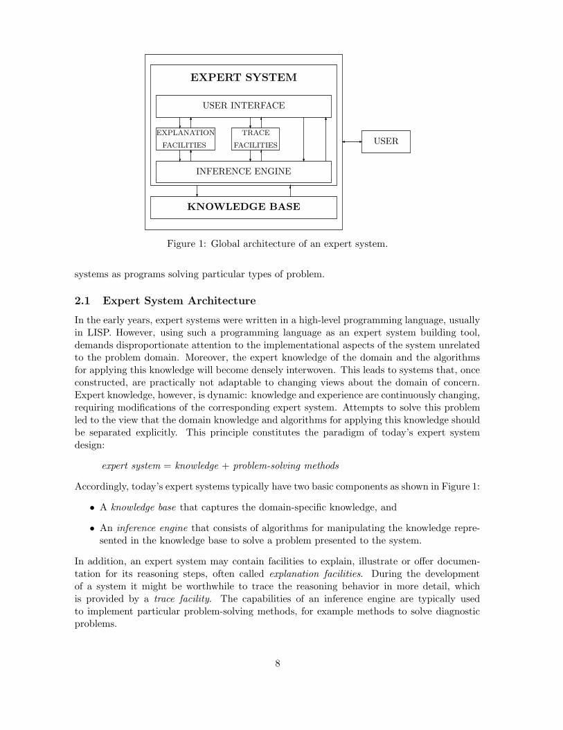
Figure 1: Global architecture of an expert system.
systems as programs solving particular types of problem.
2.1 Expert System Architecture
In the early years, expert systems were written in a high-level programming language, usuallyin LISP. However, using such a programming language as an expert system building tool,demands disproportionate attention to the implementational aspects of the system unrelatedto the problem domain. Moreover, the expert knowledge of the domain and the algorithmsfor applying this knowledge will become densely interwoven. This leads to systems that, onceconstructed, are practically not adaptable to changing views about the domain of concern.Expert knowledge, however, is dynamic: knowledge and experience are continuously changing,requiring modifications of the corresponding expert system. Attempts to solve this problemled to the view that the domain knowledge and algorithms for applying this knowledge shouldbe separated explicitly. This principle constitutes the paradigm of today’s expert systemdesign:
expert system = knowledge + problem-solving methods
Accordingly, today’s expert systems typically have two basic components as shown in Figure 1:
• A knowledge base that captures the domain-specific knowledge, and
• An inference engine that consists of algorithms for manipulating the knowledge repre-sented in the knowledge base to solve a problem presented to the system.
In addition, an expert system may contain facilities to explain, illustrate or offer documen-tation for its reasoning steps, often called explanation facilities. During the developmentof a system it might be worthwhile to trace the reasoning behavior in more detail, whichis provided by a trace facility. The capabilities of an inference engine are typically usedto implement particular problem-solving methods, for example methods to solve diagnosticproblems.
8

Modern expert systems are rarely written in a high-level programming language. Instead,they are built in a special software environment, known under various names like expert system
shells, expert-system builder tools, or knowledge-based system toolkit. An early example ofsuch an environment is EMYCIN (Essential MYCIN), a system that emerged from MYCINby stripping it of its knowledge concerning infectious disease. Other, more recent examples,include CLIPS, JESS, AION-DS. Also the PROLOG programming language is eminentlysuitable to implement expert systems.
Every expert system shell or builder tool offers a formal language, called a knowledge-
representation formalism, for encoding the domain knowledge in the knowledge base. Further-more, they provide one or more inference engines that are capable of manipulating knowledgethat is represented in the formalism. The developer of an expert system is therefore shieldedfrom most of the system’s algorithmic aspects; only the domain-specific knowledge has to beprovided and expressed in the knowledge-representation formalism, whereas the reasoning asoffered by the tool may need to be tailored to the type of problem solving required. Notethat several advantages arise from the property that a knowledge base can be developed sep-arately from the inference engine. A knowledge base can be developed and refined stepwise.Errors and inadequacies can be easily remedied without making changes to the program textnecessary. Furthermore, an expert-system builder tool can be used to develop expert systemsfor different problem domains, which may save in development time and costs.
2.2 Problem-solving Methods
As said above, the inference engine of an expert system shell is normally customized to obtainmore specific problem-solving methods. An example is a diagnostic method that is able to usecausal knowledge about the relationship between causes and the associated effects to explainobserved malfunction of a device in terms of possible causes of that malfunction. Sometimesthe same problem can be solved in different ways, using different types of knowledge anddifferent methods. For example, the faults of a device can also be diagnosed by using expertknowledge saying that a particular combination of findings is typical for the occurrence of aparticular fault. In this case, so-called heuristic associations rather than causal knowledge isused to diagnose malfunction. More about this will be said below where the formal propertiesof some methods will be examined. Typical examples of problems for which specific methodshave been developed are:
• diagnosis
• prediction
• planning and scheduling
• design
• decision making
3 Knowledge Representation and Inference
Key issue for the suitability of any expert-system builder tool are the features it offers to modelparticular problem domains. In particular the knowledge-representation formalism and thetypes of reasoning supported are of major importance. Logic, probability theory and decision
9

theory are sufficiently general to permit describing the nature of knowledge representation,inference and problem solving without having to resort to special-purpose languages.
3.1 Logic Representation and Reasoning
Expert systems usually offer a number of different ways to represent knowledge in a domain,and to reason with this knowledge automatically to derive conclusions. Although the lan-guages offered by actual systems and tools may differ in a number of ways, there are alsomany similarities. The aspects that the languages have in common can be best understoodin terms of a logical representation, as accomplished below. The role and place of logic inartificial intelligence is discussed in more detail in 6.44: Section 1.4, in the article ‘Logic inAI’.
3.1.1 Horn-clause Logic
A Horn clause or rule is a logical implication of the following form
∀x1 · · · ∀xm((A1 ∧ · · · ∧An) → B) (1)
where Ai, B are literals of the form P (t1, . . . , tq), i.e. without a negation sign, representinga relationship P between terms tk, which may involve one or more universally quantifiedvariables xj , constants and terms involving function symbols. As all variables in rules areassumed to universally quantified, the universal quantifiers are often omitted if this does notgive rise to confusion. If n = 0, then the clause consists only of a conclusion, which maybe taken as a fact. If, on the other hand, the conclusion B is empty, indicated by ⊥, therule is also called a query. If the conditions of a query are satisfied, this will give rise to acontradiction or inconsistency, denoted by ⊥, as the conclusion is empty. So, an empty clausemeans actually inconsistency.
A popular method to reason with clauses, and Horn clauses in particular, is resolution.Let R be a set of rules not containing queries, and let Q ≡ (A1 ∧ · · · ∧ An) → ⊥ be a query,then
R ∪ {Q} ` ⊥
where ` means the application of resolution, implies that the conditions
∀x1 · · · ∀xm(A1 ∧ · · · ∧An)
are not all satisfied. Since resolution is a sound inference rule, meaning that it respects thelogical meaning of clauses, it also holds that R ∪ {Q} � ⊥, or equivalently
R � ∃x1 · · · ∃xm(A1 ∧ · · · ∧An)
if R only consists of Horn clauses. This last interpretation explains why deriving inconsistencyis normally not really the goal of using resolution; rather, the purpose is to derive certain facts.Since resolution is only complete for deriving inconsistency, called refutation completeness, itis only safe to ‘derive’ knowledge in this indirect manner. There exist other reasoning methodswhich do not have this limitation. However, resolution is a simple method that is understoodin considerable depth. As a consequence, state-of-the-art resolution-based reasoners are very
10

efficient. Resolution can also be used with clauses in general, which are logical expressions ofthe form
(A1 ∧ · · · ∧An) → (B1 ∨ · · · ∨Bm)
usually represented as:
¬A1 ∨ · · · ∨ ¬An ∨B1 ∨ · · · ∨Bm
Rules of the form (1) are particularly popular as the reasoning with propositional Hornclauses is known to be possible in linear time, whereas reasoning with propositions or clausesin general (where the right-hand side consists of disjunctions of literals) is known to be NPcomplete, i.e. may require time exponential in the size of the clauses. Note that allowingnegative literals at the left-hand site of a rule is equivalent to having disjunctions at theright-hand side. Using a logical language that is more expressive than Horn-clause logicis sometimes unavoidable, and special techniques have been introduced to deal with theiradditional power.
Let KB be a knowledge base consisting of a set (conjunction) of rules, and let F be a set
of facts observed for a particular problem P, then there are generally three ways in which aproblem can be solved, yielding different types of solutions. Let P be a problem, then thereare different classes of solutions to this problem:
• Deductive solution: S is a deductive solution of a problem P with associated set ofobserved findings F iff
KB ∪ F � S (2)
and KB ∪ F 2 ⊥, where S is a set of solution formulae.
• Abductive/inductive solution: S is an abductive solution of a problem P withassociated set of observed findings F iff the following covering condition
KB ∪ S ∪K � F (3)
is satisfied, where K stands for contextual knowledge. In addition, it must hold thatKB ∪ S ∪ C 2 ⊥ (consistency condition), where C is a set of logical constraints onsolutions. For the abductive case, it is assumed that the knowledge base KB contains alogical representation of causal knowledge and S consists of facts; for the inductive case,KB consists of background facts and S, called an inductive solution, consists of rules.
• Consistency-based solution: S is a consistency-based solution of a problem P withassociated set of observed findings F iff
KB ∪ S ∪ F 2 ⊥ (4)
Note that a deductive solution is a consistent conclusion that follows from a knowledge baseKB and a set of facts, whereas an abductive solution acts as a hypothesis that explains ob-served facts in terms of causal knowledge, i.e. cause-effect relationships. An inductive solutionalso explains observed facts, but in terms of any other type of knowledge. A consistency-basedsolution is the weakest kind of solution, as it is neither required to be concluded nor is it re-quired to explain observed findings.
11
3.1.2 Objects, Attributes and Values
Even though facts or observed findings can be represented in many different ways, in manyexpert systems facts are represented in an object-oriented fashion. This means that facts aredescribed as properties, or attributes, of objects in the real world. Attributes of objects canbe either multivalued, meaning that an object may have more than one of those propertiesat the same time, or singlevalued, meaning that values of attributes are mutually exclusive.
In logic, multivalued attributes are represented by predicate symbols, e.g.:
Parent(John,Ann) ∧ Parent(John,Derek)
indicates that the ‘object’ John, represented as a constant, has two parents (the attribute ‘Par-ent’): Ann and Derek, both represented by constants. Furthermore, singlevalued attributesare represented as function symbols, e.g.
gender(John) = male
Here, ‘gender’ is taken as a singlevalued attribute, ‘John’ is again a constant object, and‘male’ is the value, also represented as a constant.
It is, of course, also possible to state general properties of objects. For example, thefollowing bi-implication:
∀x∀y∀z((Parent(x, y) ∧ Parent(y, z)) ↔ Grandparent(x, z))
defines the attribute ‘Grandparent’ in terms of the ‘Parent’ attribute.Another typical example of reasoning about properties of objects is inheritance. Here one
wishes to associate properties of objects with the classes the objects belong to, mainly becausethis yields a compact representation offering in addition insight into the general structure ofa problem domain. Consider, for example, the following knowledge base KB:
∀x(Vehicle(x) → HasWheels(x))∀x(Car(x) → Vehicle(x)∀x(Car(x) → number-of-wheels(x) = 4)
Clearly, it holds that
KB ∪ {Car(Bugatti)} � number-of-wheels(Bugatti) = 4
as the third rule expresses that as a typical property of cars. However, the knowledge basealso incorporates more general properties of cars, such as:
KB ∪ {Car(Bugatti)} � Vehicle(Bugatti)
Now, given the fact that a car is a vehicle, we can now also conclude
KB ∪ {Car(Bugatti)} � HasWheels(Bugatti)
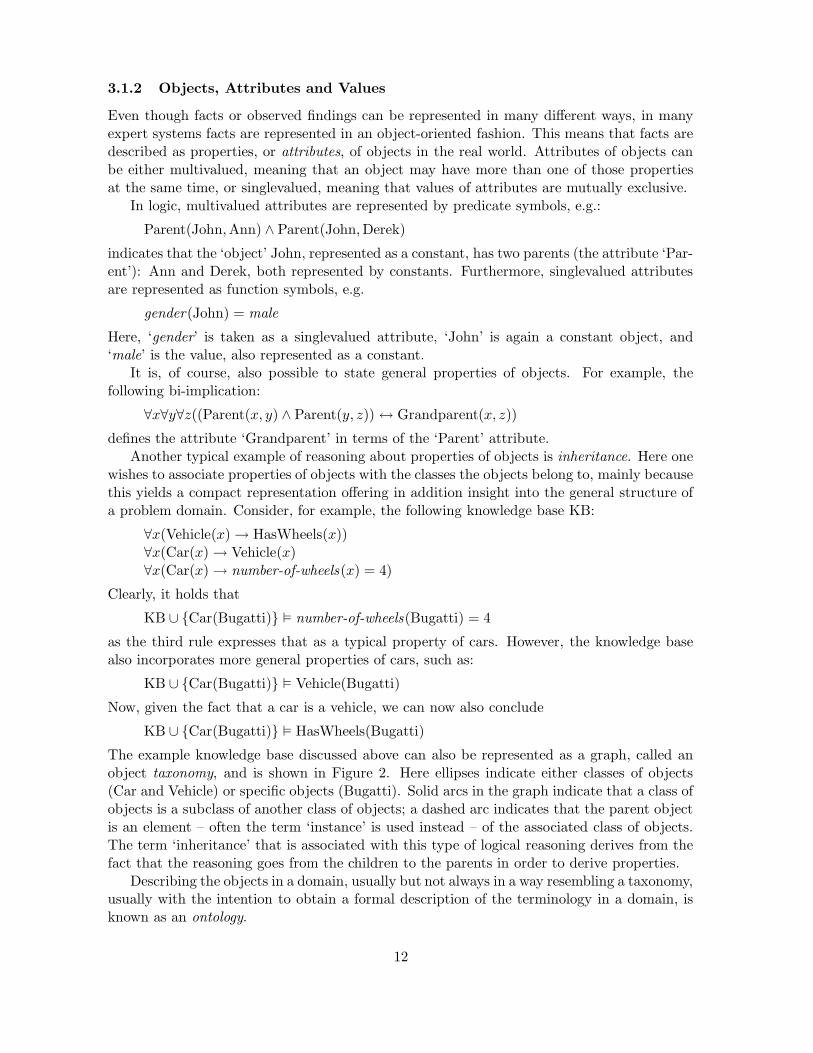
The example knowledge base discussed above can also be represented as a graph, called anobject taxonomy, and is shown in Figure 2. Here ellipses indicate either classes of objects(Car and Vehicle) or specific objects (Bugatti). Solid arcs in the graph indicate that a class ofobjects is a subclass of another class of objects; a dashed arc indicates that the parent objectis an element – often the term ‘instance’ is used instead – of the associated class of objects.The term ‘inheritance’ that is associated with this type of logical reasoning derives from thefact that the reasoning goes from the children to the parents in order to derive properties.
Describing the objects in a domain, usually but not always in a way resembling a taxonomy,usually with the intention to obtain a formal description of the terminology in a domain, isknown as an ontology.
12
Vehicle HasWheels
Car number-of-wheels = 4
Bugatti
Figure 2: An object taxonomy.
3.2 Diagnostic Problem Solving
Above, the general features of knowledge representation and inference in expert systemswere sketched. Most of the insight that has been gained in the field, however, concernsparticular methods with associated knowledge to handle classes of problems. As said above,inference or reasoning methods can be used to implement problem-solving methods. A typicalexample is the diagnosis of disorders in patients or faults in equipment by diagnostic methods.Many different methods have been developed for that purpose. Three well-known diagnosticmethods with their associated types of knowledge will be discussed in the following.
3.2.1 Deductive Diagnosis
Most of the early expert systems, including DENDRAL and MYCIN, were based on expertknowledge concerning the relationships among classes expressed by rules. In the reasoningprocess these rules were subsequently used to classify cases into categories. This problem-solving method is known as heuristic classification, as most of the knowledge encoded in therules is empirical or heuristic in nature rather than based on first principles. The form of therules is:
(c1 ∧ · · · ∧ ck∧ ∼ ck+1 ∧ · · · ∧ ∼ cn) → c
where ci is either a condition on input data or on a subclass. The rules are generalized rules,as conditions may be prefixed by a special negation sign ∼, called negation by absence. Itrepresents a special case of the closed-world assumption (CWA, cf. Secion 6.44, Article 1.3‘Logic in AI’); a condition ∼ ci only succeeds if there is at least one finding concerning theassociated attribute. Formally:
∼ A(o, v) ≡ ∃x(A(o, x) ∧ x 6= v)
for object o and value v, where o and v are constants. If the attribute A represents ameasurement or test, then negation by absence checks whether the test has been carried out,yielding a result different from the one specified.
Consider the following toy medical knowledge base KB:
13

∀x((Symptom(x, coughing)∧ ∼ Symptom(x, chest-pain) ∧ Sign(x, fever))→ Disorder(x,flu))
∀x((temp(x) > 38) → Sign(x, fever))
Then it holds that:
KB ∪ {temp(John) = 39,Symptom(John, coughing)} �NA Disorder(John, coughing)
using negation by absence (NA). Note that Sign(John, fever) is true, and may be viewed asa classification of the finding temp(John) = 39; ∼ Symptom(John, chest-pain) holds due tonegation by absence. Both rules in the knowledge base KB above are examples of heuristicclassification rules.
3.2.2 Abductive Diagnosis
In abductive diagnosis, use is made of causal knowledge to diagnose a disorder in medicine orto determine faults in a malfunctioning device. Causal knowledge can be represented in manyways, but a rather convenient and straight-forward way to represent causal knowledge is bytaking logical implication as standing for the causal relationship. Thus, rules of the form:
d1 ∧ · · · ∧ dn → f (5)
d1 ∧ · · · ∧ dn → d (6)
are obtained, where di stands for a condition concerning a defective component or disorder; theconjunctions in (5) and (6) indicate that these conditions interact to either cause observablefinding f or another abnormal condition d as effect. Sometimes uncertainty is added, usuallyrepresented in a non-numerical way as an assumption α:
d1 ∧ · · · ∧ dn ∧ αf → f (7)
d1 ∧ · · · ∧ dn ∧ αd → d (8)
The literals α may be either assumed to be true or false, meaning that f and d are a possible,but not necessary, consequences of the simultaneous occurrence of d1, . . . , dn.
An abductive diagnosis S is now simply an abductive solution, where literals in S arerestricted to di’s and α’s. The contextual knowledge may be extra conditions on rules whichcannot be derived, but must be assumed and may act to model conditional causality. Forsimplicity’s sake it is assumed here that K is empty. The set of constraints C may for instanceconsist of those findings f which have not been observed, and are assumed to be absent, i.e.¬f is assumed to hold.
Consider, for example, the causal model with set of defects and assumptions:
∆ = {fever , influenza , sport , α1, α2}
and observable findings
Φ = {chills , thirst ,myalgia ,¬chills ,¬thirst ,¬myalgia}
‘Myalgia’ means painful muscles. The following knowledge base KB contains medical knowl-edge concerning influenza and sport, both ‘disorders’ with frequent occurrence:
14
feverinfluenza chills
thirst
myalgiasport
α1
α2
Figure 3: A knowledge base with causal relations.
fever ∧ α1 → chills
influenza → fever
fever → thirst
influenza ∧ α2 → myalgia
sport → myalgia
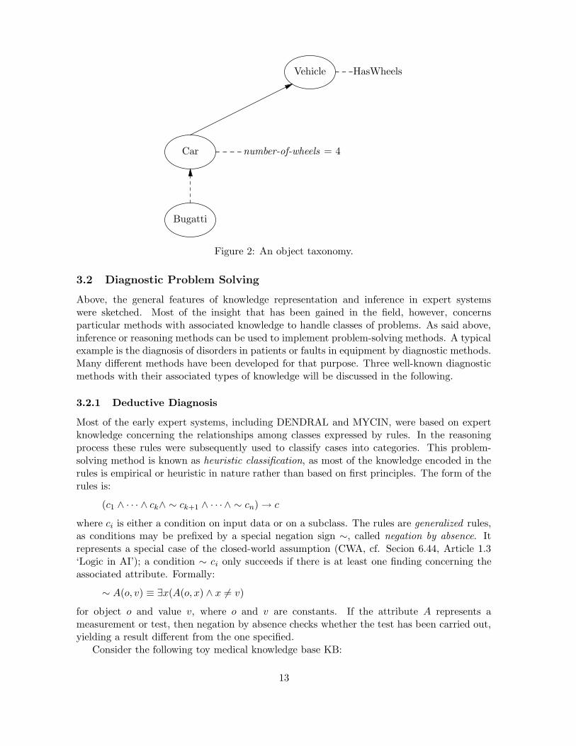
For example, influenza∧α2 → myalgia means that influenza may cause myalgia; influenza →fever means that influenza always causes fever. For illustrative purposes, a causal knowledgebase as given above is often depicted as a labelled, directed graph G, which is called a causal
net , as shown in Figure 3. Suppose that the abductive diagnostic problem with set of facts
F = {thirst ,myalgia}
must be solved. As constraints we take C = {¬chills}. There are several solutions to thisabductive diagnostic problem (for which the consistency and covering conditions are fulfilled):
S1 = {influenza , α2}S2 = {influenza , sport}S3 = {fever, sport}S4 = {fever, influenza , α2}S5 = {influenza , α2, sport}S6 = {fever, influenza , sport}S7 = {fever, influenza , α2, sport}
Note that S = {α1, α2, fever , influenza} is incompatible with the constraints C.
3.2.3 Consistency-based Diagnosis
In consistency-based diagnosis, in contrast to abductive diagnosis, the malfunctioning of adevice is diagnosed by using mainly knowledge of the normal structure and normal behaviorof the components of a device or system. For each component COMPj its normal behavioris described by logical implications of the following form:
∀x((COMPj(x) ∧ ¬Ab(x)) → Behaviorj(x))
The literal ¬Ab(x) expresses that the behavior associated with the component only holdswhen the assumption that the component is not abnormal, i.e. ¬Ab(c), is true for componentc. Sometimes knowledge of abnormal behavior is added to implications of the form above,having the form:
∀x((COMPj(x) ∧ Ab(x)) → Behaviorj(x))
15

X1
A1
A2
X2
R1
1
0
1
0 predicted
[0] observed
1 predicted
[0] observed
Figure 4: Full adder.
These may result in a reduction in the number of possible diagnoses to be considered. Logicalbehavior descriptions of the form discussed above are part of a system description, referredto by SD. In addition to the generic descriptions of the expected behavior of components, asystem description also includes logical specifications of how the components are connected toeach other (the structure of the system or device), and the names of the actual componentsmaking up the system or device. The system description is now taken as the knowledgebase KB of an expert system. Problem solving basically amounts to adopting particularassumptions about every COMPj(c), either whether Ab(c) is true or false. This sort ofreasoning is called assumption-based or hypothetical reasoning.
Consider the logical circuit depicted in Figure 4, which represents a full adder, i.e. acircuit that can be used for the addition of two bits with carry-in and carry-out bits. Thecomponents X1 and X2 represent exclusive-or gates, A1 and A2 represent and gates, and R1
represents an or gate.The system description KB consists of the following axioms:
∀x(ANDG(x) ∧ ¬Ab(x) → out(x) = and(in1 (x), in2 (x)))
∀x(XORG(x) ∧ ¬Ab(x) → out(x) = xor (in1 (x), in2 (x)))
∀x(ORG(x) ∧ ¬Ab(x) → out(x) = or(in1 (x), in2 (x)))
which describe the (normal) behavior of each individual component (gate), and
out(X1) = in2 (A2)
out(X1) = in1 (X2)
out(A2) = in1 (R1)
in1 (A2) = in2 (X2)
in1 (X1) = in1 (A1)
in2 (X1) = in2 (A1)
out(A1) = in2 (R1)
which gives information about the connections between the components, i.e. informationabout the normal structure, including some electrical relationships. Finally, the actual gatesare defined:
ANDG(A1)ANDG(A2)
16

XORG(X1)XORG(X2)ORG(R1)
Appropriate axioms of a Boolean algebra are also assumed to be available.Now, it assumed that the following observations have been made:
F = {in1 (X1) = 1, in2 (X1) = 0, in1 (A2) = 1, out(X2) = 0, out(R1) = 0}
Note that out(R1) = 1 is predicted using the model of normal structure and behavior inFigure 4, which is in contrast with the observed output out(R1) = 0. This indicates that thedevice is malfunctioning. This is also verified by noting that when assuming all componentsto behave normally, i.e. S = {¬Ab(c) | c ∈ COMPS}, it follows that
KB ∪ S ∪ F
is inconsistent. This confirms that some of the output signals observed differ from thoseexpected under the assumption that the circuit is functioning normally.
Diagnosing the problem simply consists of assuming particular components to be abnormal(Ab(c) is true for those components), and checking whether the result is still inconsistent. Ifit is not, a diagnosis has been found. So, a consistency-based diagnosis is a consistency-basedsolution S consisting of a conjunction of Ab literals, one for every component.
Consider again the example above. Here,
S = {Ab(X1),¬Ab(X2),¬Ab(A1),¬Ab(A2),¬Ab(R1)}
is a consistency-based diagnosis as
KB ∪ S ∪ F 2 ⊥
Note that X1 is possibly faulty, as assuming it to be abnormal yield no output for thiscomponents, so A2 will not receive the necessary 1 to make the output of R1 inconsistentwith the observations. Of course, the are many other solutions as well.
3.3 Configuring and Design
Configuring a device or system amounts to making choices of which and how components needto be combined to yield the requested device or system. Designing a system involves evenmore degrees of freedom than configuring a system, but is related to that task. Designingand configuring have in common that (partial) results must fulfill certain contraints andrequirements. A simple example of a design problem is shown in Figure 5.
In this design problem, filling in the box with the components of a full adder as in Figure 4would in fact be one way to obtain the requested functional behavior, but there are otherpossibilities as well. Let KB be a knowledge base consisting of generic logical descriptionsof the functional behavior of the components which may be used to design a system. Letthe set of observed findings F be equal to the set O of expected outputs; the context Kof the problem is assumed to be equal to the set of inputs I. Finally, let S stand for theresulting design solution, consisting of the actual components and interconnections betweencomponents. We call S a potential design solution iff
KB ∪ S ∪K � F
17

1
0
1
0
1
Figure 5: Functional requirements of a circuit.
i.e. the covering condition holds. Using the consistency condition with constraints C allowsus to check the solution. The result is then an acceptable design solution S. In other words,S is an inductive solution to the design problem.
In the case of the example in Figure 5, the knowledge base KB could for example consistof the following formulae:
∀x(ANDG(x) → out(x) = and(in1 (x), in2 (x)))
∀x(XORG(x) → out(x) = xor (in1 (x), in2 (x)))
∀x(ORG(x) → out(x) = or(in1 (x), in2 (x)))
which describe the behavior of each type of component. Several of the components may beused, sometimes more than once, in designing the system Y .
For the inputs and outputs it holds that:
K = {in1 (Y ) = 1, in2 (Y ) = 0, in3 (Y ) = 1}
and
F = {out1 (Y ) = 0, out2 (Y ) = 0}
A potential design solution S may include the following elements:
ANDG(A1)ANDG(A2)XORG(X1)XORG(X2)ORG(R1)
in1 (Y ) = in1 (X1)
in2 (Y ) = in2 (X1)
in3 (Y ) = in2 (A1)
out1 (Y ) = out(X2)
out2 (Y ) = out(R1)
out(X1) = in2 (A2)
out(X1) = in1 (X2)
18
out(A2) = in1 (R1)
in1 (A2) = in2 (X2)
in1 (X1) = in1 (A1)
in2 (X1) = in2 (A1)
out(A1) = in2 (R1)
Obviously, this design solution is able to derive the expected output F given the knowledgebase KB and the input K.
One of the major problems of automatic design is to cut down on the number of possibilitiesthat must be considered. Even for the simple problem discussed in the example above, findingan acceptable design solution will be intractable. By using additional domain knowledge, itmay be possible to focus the reasoning process.
3.4 Uncertainty
Up until now, it has been assumed that in representing and solving a problem in a domaindealing with uncertainty is not of major importance. As this does not hold for many prob-lems, the possibility to represent and reason with the uncertainty associated with a problemis clearly of significance. There have been a number of early attempts where researchers haveaugmented rule-based, logical methods with uncertainty methods, usually different from prob-ability theory, although sometimes also related. However, those methods are now outdated,and have been replaced by methods which take probability theory as a starting point. In thecontext of expert systems, in particular the formalism of Bayesian belief networks has beensuccessful. Expert systems built using this formalism are called probabilistic expert systems
or normative expert systems.A Bayesian belief network B = (G,Pr), also called causal probabilistic network, is a di-
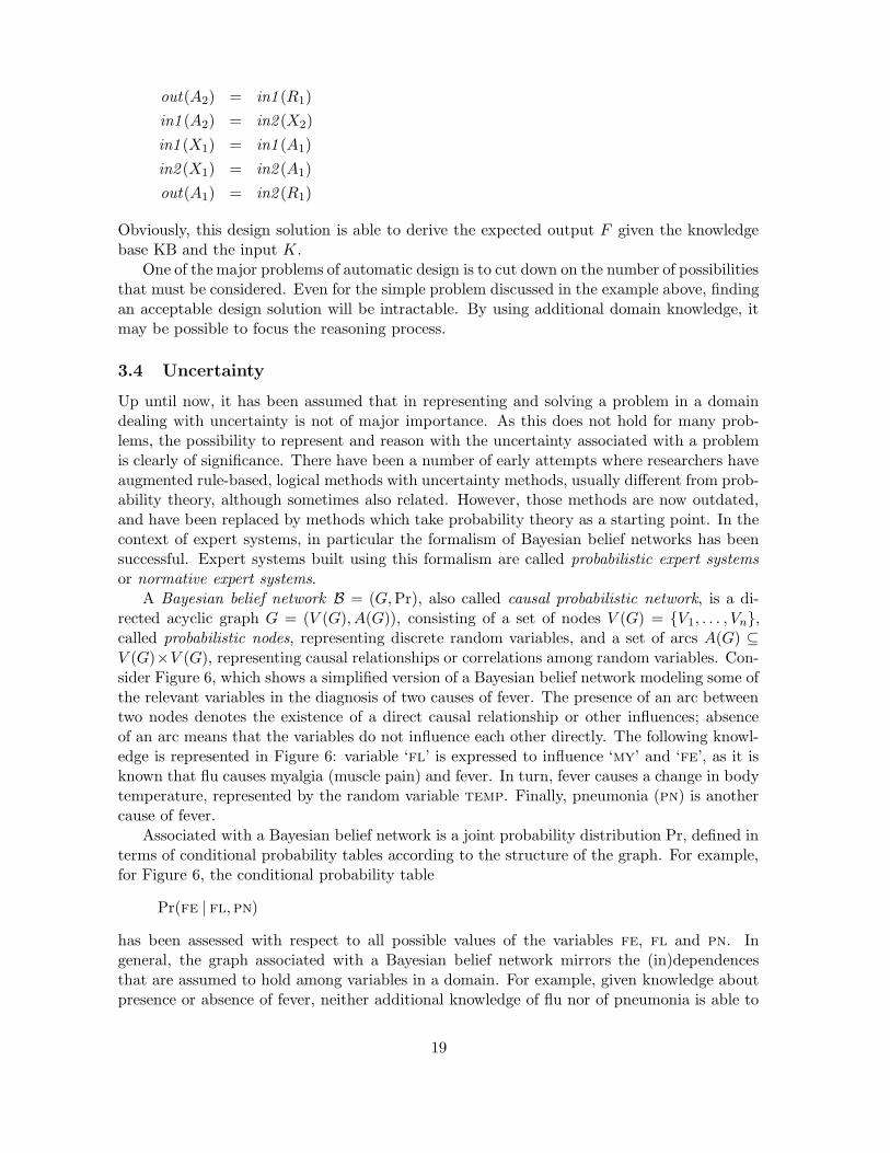
rected acyclic graph G = (V (G), A(G)), consisting of a set of nodes V (G) = {V1, . . . , Vn},called probabilistic nodes, representing discrete random variables, and a set of arcs A(G) ⊆V (G)×V (G), representing causal relationships or correlations among random variables. Con-sider Figure 6, which shows a simplified version of a Bayesian belief network modeling some ofthe relevant variables in the diagnosis of two causes of fever. The presence of an arc betweentwo nodes denotes the existence of a direct causal relationship or other influences; absenceof an arc means that the variables do not influence each other directly. The following knowl-edge is represented in Figure 6: variable ‘fl’ is expressed to influence ‘my’ and ‘fe’, as it isknown that flu causes myalgia (muscle pain) and fever. In turn, fever causes a change in bodytemperature, represented by the random variable temp. Finally, pneumonia (pn) is anothercause of fever.
Associated with a Bayesian belief network is a joint probability distribution Pr, defined interms of conditional probability tables according to the structure of the graph. For example,for Figure 6, the conditional probability table
Pr(fe | fl,pn)
has been assessed with respect to all possible values of the variables fe, fl and pn. Ingeneral, the graph associated with a Bayesian belief network mirrors the (in)dependencesthat are assumed to hold among variables in a domain. For example, given knowledge aboutpresence or absence of fever, neither additional knowledge of flu nor of pneumonia is able to
19
Flu (FL)(yes/no)
Pneumonia (PN)(yes/no)
Fever (FE)(yes/no)
Myalgia (MY)(yes/no)
TEMP(≤ 37.5/> 37.5)
Pr(FL = y) = 0.1
Pr(PN = y) = 0.05
Pr(FE = y|FL = y,PN = y) = 0.95
Pr(FE = y|FL = n,PN = y) = 0.80
Pr(FE = y|FL = y,PN = n) = 0.88
Pr(FE = y|FL = n,PN = n) = 0.001
Pr(MY = y|FL = y) = 0.96
Pr(MY = y|FL = n) = 0.20
Pr(TEMP ≤ 37.5|FE = y) = 0.1
Pr(TEMP ≤ 37.5|FE = n) = 0.99
Figure 6: Bayesian network B = (G,Pr) with associated joint probability distribution Pr(only probabilities Pr(X = y |π(X)) are shown, as Pr(X = n |π(X)) = 1−Pr(X = y |π(X))).
NO
YES
MYALGIA
NO
YES
FLU
NO
YES
FEVER
NO
YES
PNEUMONIA
<=37.5
>37.5
TEMP
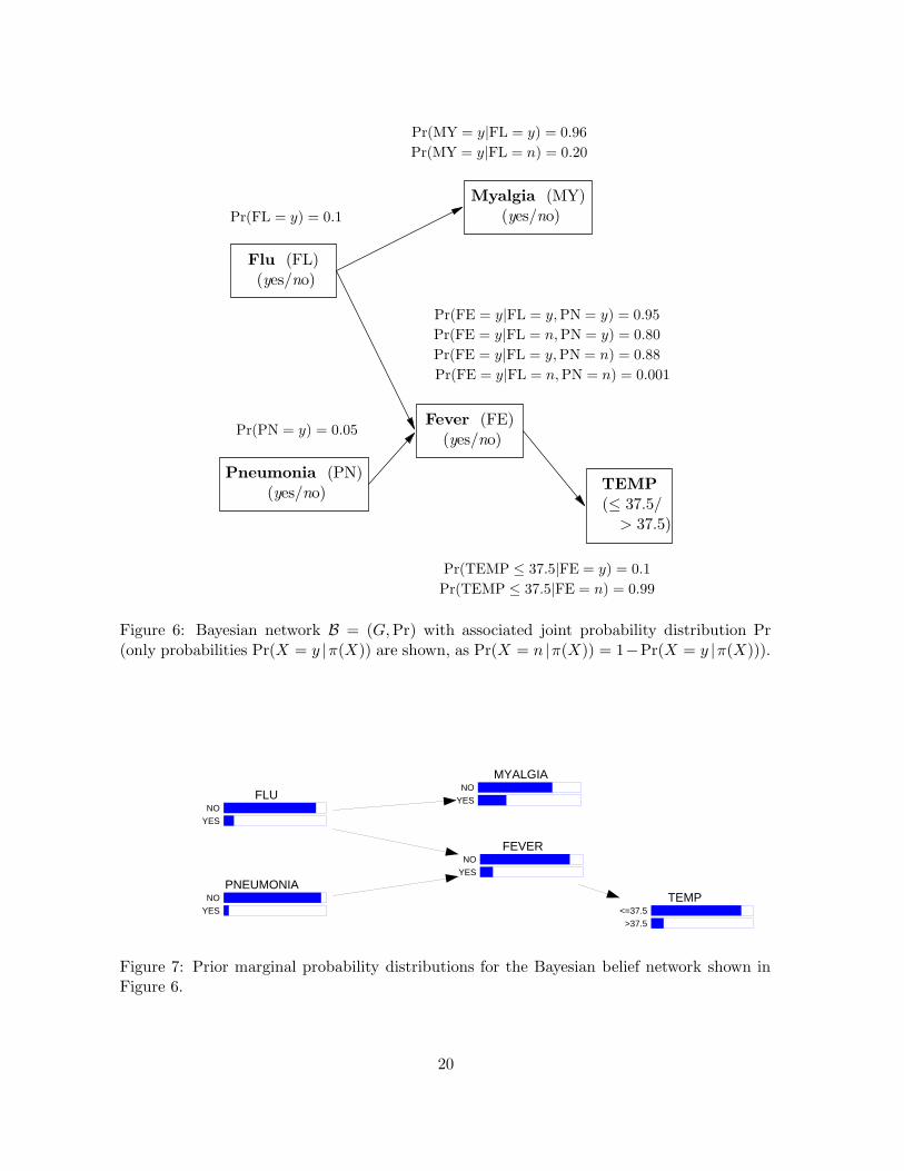
Figure 7: Prior marginal probability distributions for the Bayesian belief network shown inFigure 6.
20
NO
YES
MYALGIA
NO
YES
FLU
NO
YES
FEVER
NO
YES
PNEUMONIA
<=37.5
>37.5
TEMP
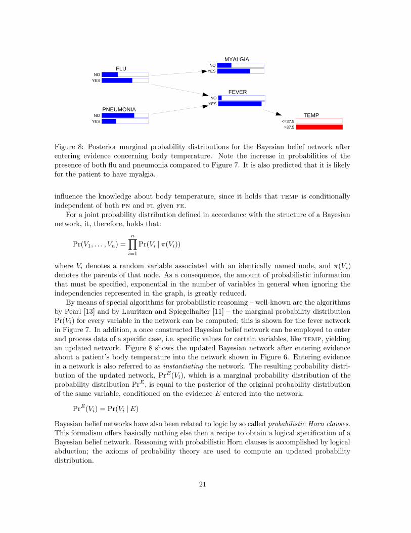
Figure 8: Posterior marginal probability distributions for the Bayesian belief network afterentering evidence concerning body temperature. Note the increase in probabilities of thepresence of both flu and pneumonia compared to Figure 7. It is also predicted that it is likelyfor the patient to have myalgia.
influence the knowledge about body temperature, since it holds that temp is conditionallyindependent of both pn and fl given fe.
For a joint probability distribution defined in accordance with the structure of a Bayesiannetwork, it, therefore, holds that:
Pr(V1, . . . , Vn) =
n∏
i=1
Pr(Vi | π(Vi))
where Vi denotes a random variable associated with an identically named node, and π(Vi)denotes the parents of that node. As a consequence, the amount of probabilistic informationthat must be specified, exponential in the number of variables in general when ignoring theindependencies represented in the graph, is greatly reduced.
By means of special algorithms for probabilistic reasoning – well-known are the algorithmsby Pearl [13] and by Lauritzen and Spiegelhalter [11] – the marginal probability distributionPr(Vi) for every variable in the network can be computed; this is shown for the fever networkin Figure 7. In addition, a once constructed Bayesian belief network can be employed to enterand process data of a specific case, i.e. specific values for certain variables, like temp, yieldingan updated network. Figure 8 shows the updated Bayesian network after entering evidenceabout a patient’s body temperature into the network shown in Figure 6. Entering evidencein a network is also referred to as instantiating the network. The resulting probability distri-bution of the updated network, PrE(Vi), which is a marginal probability distribution of theprobability distribution PrE , is equal to the posterior of the original probability distributionof the same variable, conditioned on the evidence E entered into the network:
PrE(Vi) = Pr(Vi |E)
Bayesian belief networks have also been related to logic by so called probabilistic Horn clauses.This formalism offers basically nothing else then a recipe to obtain a logical specification of aBayesian belief network. Reasoning with probabilistic Horn clauses is accomplished by logicalabduction; the axioms of probability theory are used to compute an updated probabilitydistribution.
21
Pneumonia (PN)(yes/no)
Fever (FE)(yes/no)
TEMP(≤ 37.5/> 37.5)
Coughing (CO)(yes/no)
Pneumococcus (PP)(yes/no)
Coverage (CV)(yes/no)
Therapy (TH)(penicillin/no-penicillin) U
Pr(PN = y | PP = y) = 0.77
Pr(PN = y | PP = n) = 0.01
Pr(FE = y | PN = y) = 0.95
Pr(FE = y | PN = n) = 0.001
Pr(CO = y | PN = y) = 0.80
Pr(CO = y | PN = n) = 0.05
Pr(TEMP ≤ 37.5 | FE = y) = 0.1
Pr(TEMP ≤ 37.5 | FE = n) = 0.99
Pr(CV = y | PP = y,TH = pc) = 0.80
Pr(CV = y | PP = n,TH = pc) = 0.0
Pr(CV = y | PP = y,TH = npc) = 0.0
Pr(CV = y | PP = n,TH = npc) = 1.0
Pr(PP = y) = 0.1
u(CV = y) = 1000
u(CV = n) = 0
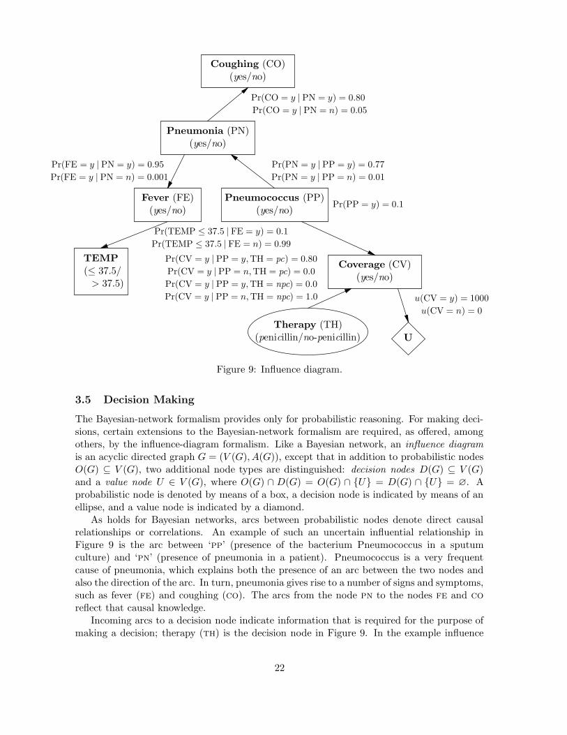
Figure 9: Influence diagram.
3.5 Decision Making
The Bayesian-network formalism provides only for probabilistic reasoning. For making deci-sions, certain extensions to the Bayesian-network formalism are required, as offered, amongothers, by the influence-diagram formalism. Like a Bayesian network, an influence diagram
is an acyclic directed graph G = (V (G), A(G)), except that in addition to probabilistic nodesO(G) ⊆ V (G), two additional node types are distinguished: decision nodes D(G) ⊆ V (G)and a value node U ∈ V (G), where O(G) ∩ D(G) = O(G) ∩ {U} = D(G) ∩ {U} = ∅. Aprobabilistic node is denoted by means of a box, a decision node is indicated by means of anellipse, and a value node is indicated by a diamond.
As holds for Bayesian networks, arcs between probabilistic nodes denote direct causalrelationships or correlations. An example of such an uncertain influential relationship inFigure 9 is the arc between ‘pp’ (presence of the bacterium Pneumococcus in a sputumculture) and ‘pn’ (presence of pneumonia in a patient). Pneumococcus is a very frequentcause of pneumonia, which explains both the presence of an arc between the two nodes andalso the direction of the arc. In turn, pneumonia gives rise to a number of signs and symptoms,such as fever (fe) and coughing (co). The arcs from the node pn to the nodes fe and co
reflect that causal knowledge.Incoming arcs to a decision node indicate information that is required for the purpose of
making a decision; therapy (th) is the decision node in Figure 9. In the example influence
22
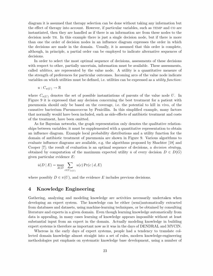
diagram it is assumed that therapy selection can be done without taking any information butthe effect of therapy into account. However, if particular variables, such as temp and co areinstantiated, then they are handled as if there is an information arc from these nodes to thedecision node th. In this example there is just a single decision node, but if there is morethan one the order of decision nodes in an influence diagram expresses the order in whichthe decisions are made in the domain. Usually, it is assumed that this order is complete,although, in principle, a partial order can be employed to indicate alternative sequences ofdecisions.
In order to select the most optimal sequence of decisions, assessments of these decisionswith respect to other, partially uncertain, information must be available. These assessments,called utilities, are represented by the value node. A utility is a quantitative measure ofthe strength of preferences for particular outcomes. Incoming arcs of the value node indicatevariables on which utilities must be defined, i.e. utilities can be expressed as a utility function:
u : Cπ(U) → R
where Cπ(U) denotes the set of possible instantiations of parents of the value node U . InFigure 9 it is expressed that any decision concerning the best treatment for a patient withpneumonia should only be based on the coverage, i.e. the potential to kill in vivo, of thecausative bacterium Pneumococcus by Penicillin. In this simplified example, many factorsthat normally would have been included, such as side-effects of antibiotic treatment and costsof the treatment, have been omitted.
As for Bayesian networks, the graph representation only denotes the qualitative relation-ships between variables; it must be supplemented with a quantitative representation to obtainan influence diagram. Example local probability distributions and a utility function for thedomain of antibiotic treatment of pneumonia are shown in Figure 9. Various algorithms toevaluate influence diagrams are available, e.g. the algorithms proposed by Shachter [18] andCooper [7]; the result of evaluation is an optimal sequence of decisions, a decision strategy,obtained by computation of the maximum expected utility u of every decision D ∈ D(G)given particular evidence E:
u(D |E) = maxd∈D
∑
c∈Cπ(U)
u(c) Pr(c | d,E)
where possibly D ∈ π(U), and the evidence E includes previous decisions.
4 Knowledge Engineering
Gathering, analyzing and modeling knowledge are activities necessarily undertaken whendeveloping an expert system. The knowledge can be either (semi)automatically extractedfrom databases and datasets, using machine-learning techniques, or be obtained by consultingliterature and experts in a given domain. Even though learning knowledge automatically fromdata is appealing, in many cases learning of knowledge appears impossible without at leastsubstantial input from an expert in the domain. Actually modeling knowledge in buildingexpert systems is therefore as important now as it was in the days of DENDRAL and MYCIN.
Whereas in the early days of expert systems, people had a tendency to translate col-lected domain knowledge almost straight into a set of rules, modern knowledge-engineeringmethodologies put emphasis on systematic knowledge base development, using a number of
23
cover
complaint
causalmodel
hypothesis predict
manifestationmodel
expectedfinding
obtainactualfinding
compare
result
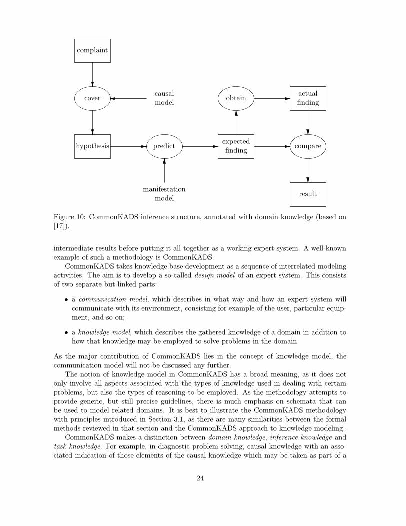
Figure 10: CommonKADS inference structure, annotated with domain knowledge (based on[17]).
intermediate results before putting it all together as a working expert system. A well-knownexample of such a methodology is CommonKADS.
CommonKADS takes knowledge base development as a sequence of interrelated modelingactivities. The aim is to develop a so-called design model of an expert system. This consistsof two separate but linked parts:
• a communication model, which describes in what way and how an expert system willcommunicate with its environment, consisting for example of the user, particular equip-ment, and so on;
• a knowledge model, which describes the gathered knowledge of a domain in addition tohow that knowledge may be employed to solve problems in the domain.
As the major contribution of CommonKADS lies in the concept of knowledge model, thecommunication model will not be discussed any further.
The notion of knowledge model in CommonKADS has a broad meaning, as it does notonly involve all aspects associated with the types of knowledge used in dealing with certainproblems, but also the types of reasoning to be employed. As the methodology attempts toprovide generic, but still precise guidelines, there is much emphasis on schemata that canbe used to model related domains. It is best to illustrate the CommonKADS methodologywith principles introduced in Section 3.1, as there are many similarities between the formalmethods reviewed in that section and the CommonKADS approach to knowledge modeling.
CommonKADS makes a distinction between domain knowledge, inference knowledge andtask knowledge. For example, in diagnostic problem solving, causal knowledge with an asso-ciated indication of those elements of the causal knowledge which may be taken as part of a
24

hypothesis S, and elements which correspond to findings that may be actually observed in thereal world would be classified as domain knowledge. Definition (3) of an abductive diagnosiswould be looked upon as inference knowledge, as it describes which hypotheses (for examplediagnostic hypotheses) would be accepted as a (diagnostic) solution. Finally, task knowledgein this case would concern procedures that describe how hypotheses can be generated andtested against observed findings, using domain and inference knowledge. An example of adiagram of a diagnostic inference model is shown in Figure 10.
Rather than offering a set of formal techniques to specify a knowledge model, most ofCommonKADS concerns semiformal techniques, which often have no precise semantics. Bothdiagrammatic and textual specifications are used to represent a knowledge model. However,there have been several attempts to offer a formal underpinning of the approach in a mannersimilar to that discussed in Section 3.1.
Even though the CommonKADS methodology suggests that it covers most types of expertsystem development, this is not the case for expert systems based on probability theory anddecision theory, which can be viewed upon as one of the omissions of the approach.
Important final aspects of expert-system development are the evaluation and validationof the resulting system. This is done by comparing the system with the original requirementof the system (validation) and by studying the problem-solving behavior of the system forproblem cases (laboratory test) and in the working environment (field test).
5 Conclusions
In this article, the most important topics in the field of expert systems have been discussed.The central issue of expert-system development is knowledge modeling, and many differentformalisms are available today to model the features of a problem domain accurately. As aconsequence, it is not always easy to decide whether a particular approach to developing anexpert system is the right one.
Bibliography
[1] Brachman R.J. (1983). What IS-A is and isn’t: an analysis of taxonomic links in semanticnetworks. IEEE Computer, vol. 16, no. 10, pp. 30–36. [This is a classic paper about themeaning of the IS-A relation as used in taxonomies describes.]
[2] Buchanan B.G., Shortliffe E.H. (1984). Rule-based Expert Systems: The MYCIN Exper-iments of the Stanford Heuristic Programming Project. Addison-Wesley, Reading, MA.[Collection of papers about many different aspects of the MYCIN project.]
[3] Buchanan BG, Sutherland G.L., Feigenbaum E.A. (1969). Heuristic DENDRAL: a pro-gram for generating explanatory hypotheses in organic chemistry. In: Machine Intelli-gence (B. Meltzer, D. Michie, eds.), 4, Edinburgh University Press, Edinburgh. [Descrip-tion of the early expert system DENDRAL.]
[4] Bylander T, Allemang D., Tanner M.C., Josephson J.R. (1992). The computational com-plexity of abduction. In Knowledge Representation (R.J. Brachman, H.J. Levesque andR. Reiter, eds.), pp. 25–60. The MIT Press, Cambridge, MA. [Ground-breaking paperabout the computational complexity of different abductive methods.]
25

[5] Clancey W.J. (1985). Heuristic classification. Artificial Intelligence, vol. 27, pp. 289–350.[Paper analyzing reasoning with heuristic association rules.]
[6] Console L., Theseider Dupre D.,Torasso P. (1989). A theory of diagnosis for incompletecausal models. In: Proceedings of the 10th International Joint Conference on Artifi-cial Intelligence, pp. 1311–1317. [Paper introducing the use of incompleteness literals inabductive diagnosis.]
[7] Cooper G.F. (1988). A method for using belief networks as influence diagrams. In: Pro-ceedings of the 4th Workshop on Uncertainty in Artificial Intelligence, pp. 55–63. [Paperproposing an algorithm to reason with an influence diagram, based on a Bayesian-belief-network algorithm.]
[8] Forbus K.D., De Kleer J. (1993). Building Problem Solvers. The MIT Press, Cambridge,MA. [Book about the principles of and the building of problem solvers, in particularconsistency-based ones.]
[9] Glymour C., Cooper G.F. (1999). Computation, Causation & Discovery. MIT Press,Menlo Park, CA. [Collection of papers about discovering Bayesian belief networks andcausal theories from data.]
[10] De Kleer J., Williams B.C. (1987). Diagnosing multiple faults. Artificial Intelligence,vol. 32, pp. 97–130. [First paper describing the basic ideas behind consistency-baseddiagnosis.]
[11] Lauritzen S.L., Spiegelhalter D.J. (1987). Local computations with probabilities ongraphical structures and their application to expert systems. Journal of the Royal Sta-tistical Society (Series B), vol. 50, pp. 157–224. [Paper introducing a new methods in1987, now widely used, for probabilistic reasoning with Bayesian belief networks.]
[12] Lucas P.J.F., Van der Gaag L.C. (1991). Principles of Expert Systems. Addison-Wesley,Wokingham, UK. [Textbook on expert system that emphasizes knowledge representationand inference, including formal meanings of knowledge-representation formalisms.]
[13] Pearl J. (1988). Probabilistic Reasoning in Intelligent Systems: Networks of PlausibleInference. Morgan Kaufmann, Palo Alto. [First, ground-breaking book about Bayesianbelief networks.]
[14] Peng Y, Reggia J.A. (1990). Abductive inference models for diagnostic problem solving.Springer-Verlag, New York. [Book describing a restrictive method for abductive diagnosisusing set theory.]
[15] Poole D. (1989). Explanation and prediction: an architecture for default and abductivereasoning. Computational Intelligence, vol. 5, no. 2, pp. 97–110. [Paper describing alogical approach to diagnostic reasoning.]
[16] Reiter R. (1987). A theory of diagnosis from first principles. Artificial Intelligence, vol.32, pp. 57–95. [First paper formalizing consistency-based diagnosis.]
26

[17] Schreiber A.Th., Akkermans H., Anjewierden A., De Hoogh R., Shadbolt N., Van deVelde W., Wielinga B. (2000). Knowledge Engineering and Management: The Com-monKADS Methodology. MIT Press, Menlo Park, CA. [Book presenting an overview ofthe CommonKADS knowledge-engineering methodology.]
[18] Shachter R.D. (1986). Evaluating influence diagrams. Operation Research, vol. 34, no. 6,pp. 871–882. [First paper proposing an algorithm to manipulate influence diagrams forthe purpose of decision making.]
27