introduction to wind energy systems - società italiana di...
TRANSCRIPT

Summer School of Physical Societies, Varenna 01.08.2012
Introduction to Wind Energy Systems
Hermann-Josef Wagner
Institute for Energy Systems and Energy Economy Ruhr-University Bochum, Germany

Structure of my presentation
• Present status of wind energy use • Physical and meteorological basics • Techniques of wind converters • Off shore windparks
• Wind use in Europe

Electricity from wind energy
Source: DEWI Magazin,Feb. 2012,ISSN 0946-1787,p.30-43
Status of installed wind power
Rated Capacity
End of 2011 [GW] Share
worldwide [%]
China 63 26
USA 47 20
Germany 29 12
Spain 22 9
India 16 7
Italy 7 3
France 7 3
UK 7 3
Canada 5 2
Portugal 4 2
Remaining countries 32 13
Total 239 100
Structure of my presentation
• Present status of wind energy use • Physical and meteorological basics • Techniques of wind converters • Off shore windparks
• Wind use in Europe

Energy and power density of wind
Derivative of the equation with steady velocity of wind v
Kinetic energy E of a mass element Δ m
Efficiency
V = volume
ρL = density of air = 1,2 kg/m³

Velocity triangle at the rotor blade
Bird‘s eye view of horizontally positioned rotor blades
Bird‘s eye view of vertically positioned rotor blades
rotor plane
roto
r axi
s
rotor plane
rotor axis
profile chord for the pitch angle applies: αA should be optimal, besides use b as a set variable in accordance to
v0 and u (revolution)
αA = f (β, v0, u) = arctan (v0/u) – b
aA = angle of attack (angle between profile chord and relative approach velocity )
b = pitch angle
g = angle between wind velocity and approach velocity
u = circumferential velocity
v0 = wind velocity in the rotor axis
w = relative approach velocity (Es gilt: )

The velocities and forces acting on a blade
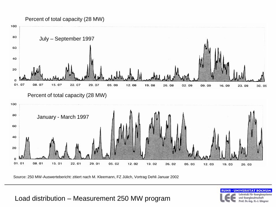
Load distribution – Measurement 250 MW program
Percent of total capacity (28 MW)
Percent of total capacity (28 MW)
July – September 1997
January - March 1997
Source: 250 MW-Auswertebericht: zitiert nach M. Kleemann, FZ Jülich, Vortrag Dehli Januar 2002

Structure of my presentation
• Present status of wind energy use • Physical and meteorological basics • Techniques of wind converters • Off shore windparks
• Wind use in Europe

Different types of wind energy converters
Solar chimney power plant

Dimensioning of wind energy conversion systems
Definition of the rotor power P = 0,5 · cp · ρ · A · v3
Dependence of the power coefficient cp
cp interdepends with three factors:
1. Blade design, i.e. ratio of buoyancy factor to friction factor = glide ratio. The glide ratio affects the tip speed ratio strongly.
2. Ratio blade tip velocity to wind velocity = tip speed ratio λ Dutchmen windmills: λ = 2 -4 Modern 3-blade conversion systems: λ = 3 -12 Limitation of the tip speed ratio in practice due to sound emissions (blade tip velocity contributes to sound emissions with the power of six)
3. Ratio of the sum of all blade areas to the rotor circular area A = solidity ratio. which is simplified the number of rotor blades.
v = wind velocity
A = rotor circular area = π l 2 with l = rotor length
ρ = air density
cp = power coefficient
„Cooking recipes“ for dimensioning of wind energy conversion systems
1. High glide ratios lead to high tip speed ratios and therefore to a large power coefficient cp Modern converters with good aerodynamic profiles rotate quickly.
2. Simple profiles with a smaller glide ratio have smaller tip speed ratios. Therefore is a large solidity ratio required to achieve an increase of the power coefficient. Slow rotating converters have poor aerodynamic profiles and a high number of blades
3. Glide ratio and tip speed ratio have a larger influence on the power coefficient than the solidity ratio.
Number of blades for fast rotating converters has a secondary relevance (in practice mostly 2-3).
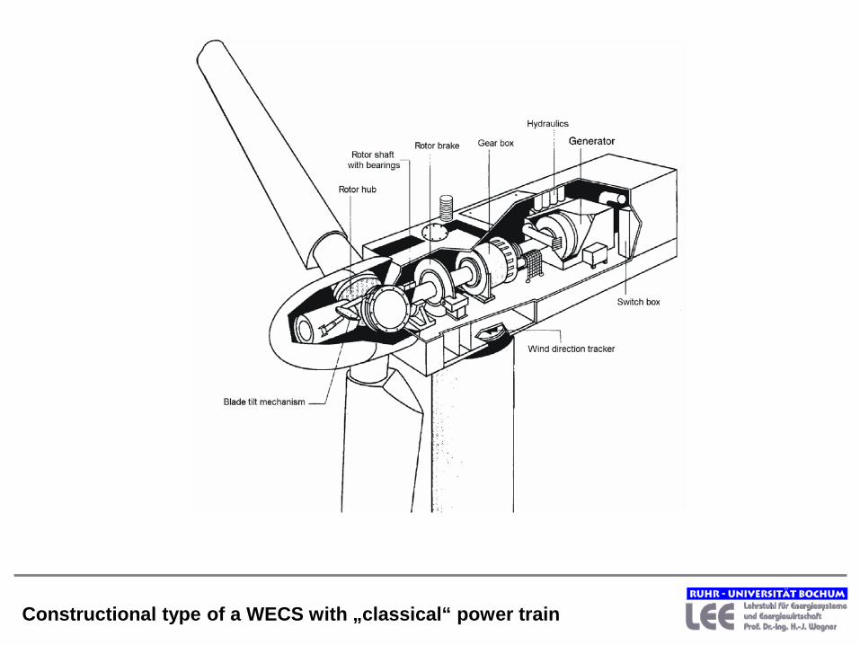
Constructional type of a WECS with „classical“ power train

Source: Nordex AG
Assembling of a wind converter by Nordex AG
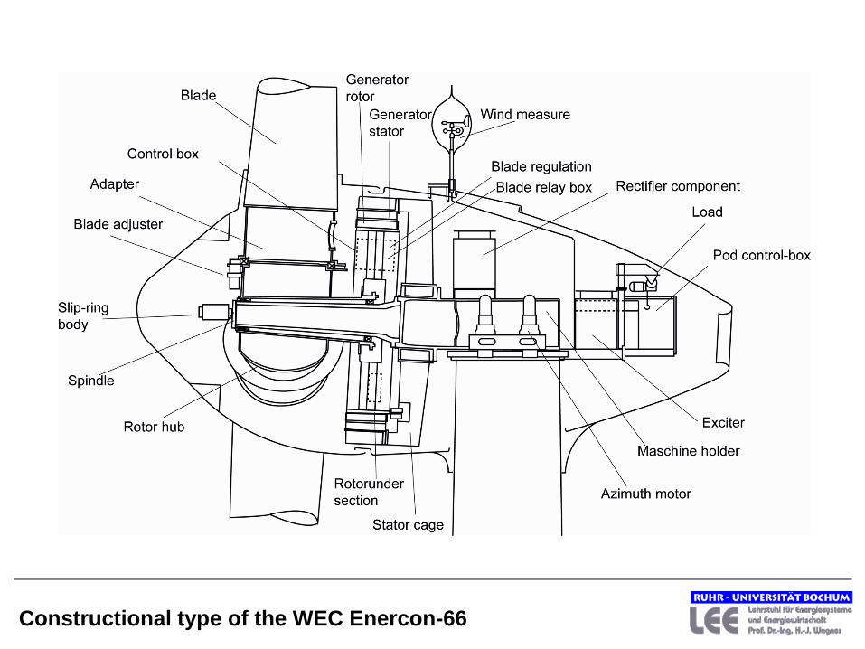
Constructional type of the WEC Enercon-66

Source: ENERCON GmbH
Windenergy converter without gearbox by Enercon
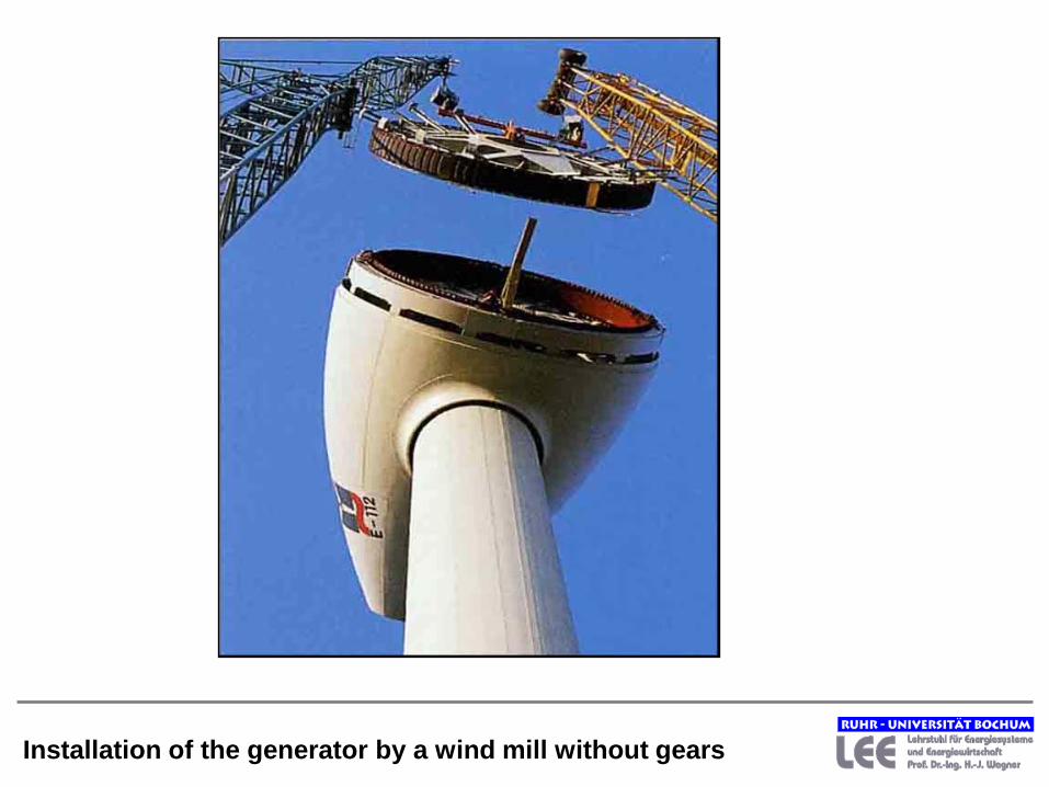
Installation of the generator by a wind mill without gears

Curve family of a fast rotating rotor
Adjusting of the revolutions and the line frequency with:
• controllable gearing or
• changeable number of pole pairs (electrical gearing) or
• asynchronous generator with extended slip or
• intermediate direct currency link

New devices need testing: Problems with gear boxes

Structure of my presentation
• Present status of wind energy use • Physical and meteorological basics • Techniques of wind converters • Off shore windparks
• Wind use in Europe

Possible foundations of offshore wind converters
Monopile until 20 m deep of
water Steel- or concrete
construction Gravity foundation
until 10 m deep of water
Steel- or concrete construction Tripod, Jacket
more than 20 m deep of water
Steel construction
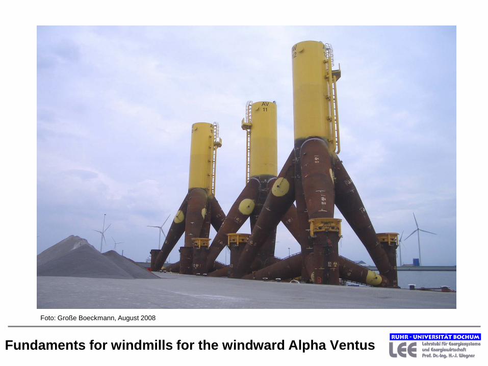
Fundaments for windmills for the windward Alpha Ventus
Foto: Große Boeckmann, August 2008
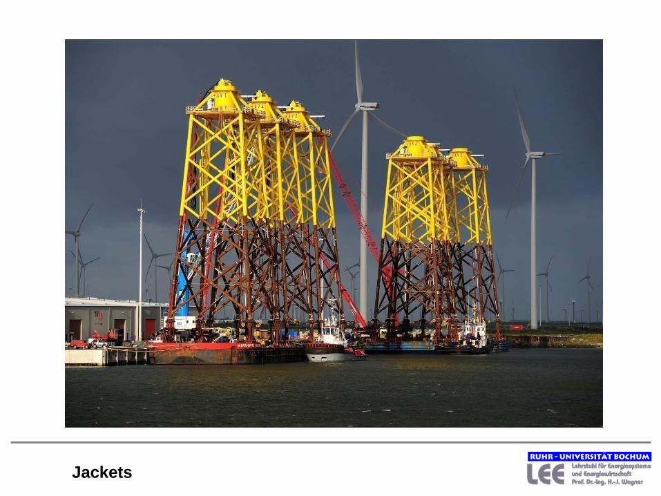
Jackets

Offshore wind projects in the German part of north sea Source: BWK Jan./Feb. 2012

Offshore windfarm in Denmark (Malmo-Copenhagen region)
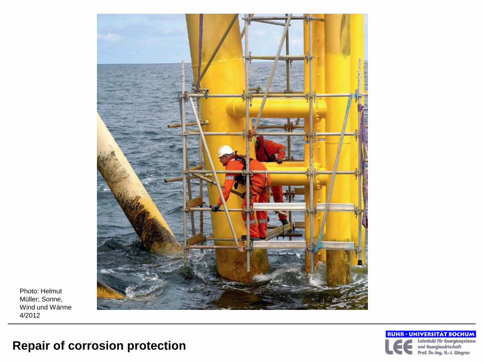
Repair of corrosion protection
Photo: Helmut Müller; Sonne, Wind und Wärme 4/2012

Structure of my presentation
• Present status of wind energy use • Physical and meteorological basics • Techniques of wind converters • Off shore windparks
• Wind use in Europe
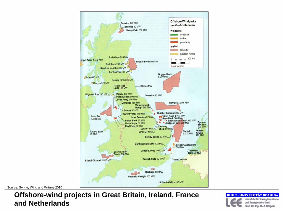
Offshore-wind projects in Great Britain, Ireland, France and Netherlands
Source: Sonne, Wind und Wärme 2010
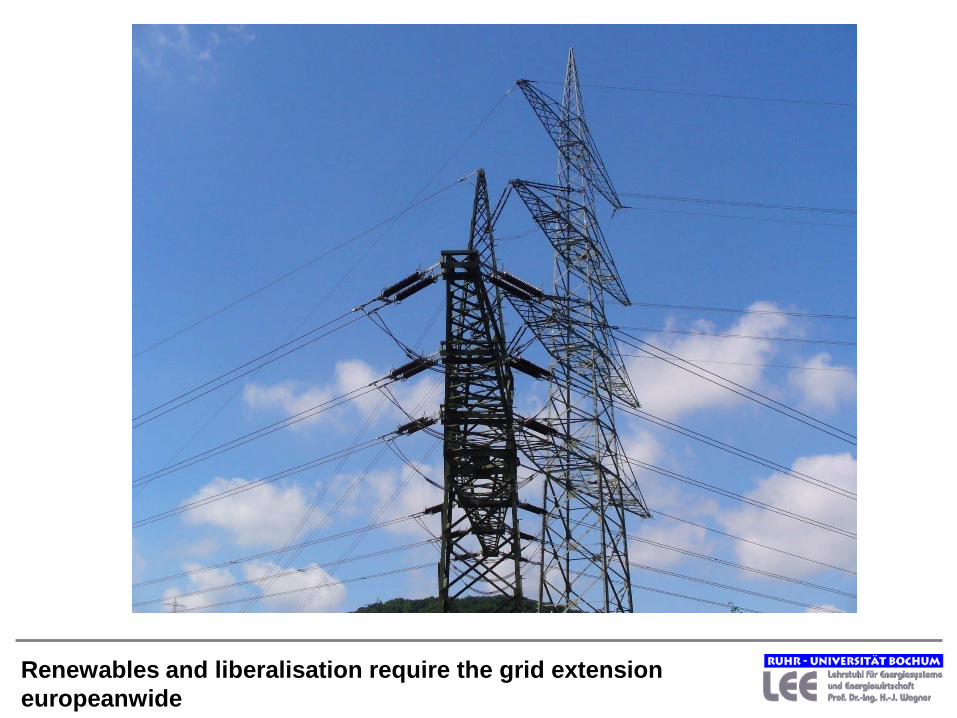
Renewables and liberalisation require the grid extension europeanwide

Thank you for your attention
www.lee.rub.de
For discussion

Shares of the suppliers in the world market
Source: DEWI-Magazin, Nr. 33, 2008
Basis: New erected capacity 2007: about 22 000 MW