introduction to verilog - eclipse cluster · pdf fileuse of gate level primitives ... verilog...
TRANSCRIPT

Department of Computer Science and Electrical Engineering
Introduction to VerilogProf. Ryan Robucci
http://6004.csail.mit.edu/6.371/handouts/L0{2,3,4}.pdfhttp://www.asic-world.com/verilog/http://www.verilogtutorial.info/

Why use an HDL?Why use an HDL?● Want an executable functional specification
– Document exact behavior of all the modules and their Interfaces– Executable models can be tested & refined until they do what you want
● Too much detail at the transistor and mask levels– Can’t debug 1M transistors as individual analog components– Abstract away “unnecessary” details– Play by the rules: don’t break abstraction with clever hacks
● HDL description is first step in a mostly automated process to build an implementation directly from the behavioral model
AbstractionAbstraction● Abstraction is a cornerstone of digital design.● HDLs allow us to model hardware with varying
levels of abstraction. They allow us to flexibly describe and represent not only functionality, but also implementation and structure at varying degrees. For the purpose of simulation, the most significant difference from functional modeling in software is the level of support for representing timing (delays) and concurrent execution.

A Tale of Two HDLsA Tale of Two HDLs
http://6004.csail.mit.edu/6.371/handouts/L03.pdf

Important Verilog Coding StylesImportant Verilog Coding Styles● Structural models: basically a hierarchical netlist starting
with “primitives” and modules built using other styles.
● Dataflow models: combinational logic described using expressions
● Behavioral models: This level describes a system by concurrent “algorithms” (Behavioral). Each algorithm itself is sequential, that means it consists of a set of instructions that are executed one after the other. There is no regard to the structural realization of the design.
● Register-Transfer Level (RTL) register-focused design. – Registers are identified, and the movement of data
between them at specific specified timing events like clock edges logic is described. Modern RTL code definition is "Any code that is synthesizable is called RTL code".

StructuralStructural● Structural models: basically a hierarchical netlist with “primitives” (built-in
Verilog logic gates, or instances of library modules).
● Instantiation of Modules
● Use of Gate Level Primitives
– Within the logic level the characteristics of a system are described by logical links and their timing properties. All signals are discrete signals. They can only have definite logical values (`0', `1', `X', `Z`). The usable operations are predefined logic primitives (AND, OR, NOT etc gates). Using gate level modeling might not be a good idea for any level of logic design. Gate level code is generated by tools like synthesis tools and this netlist is used for gate level simulation and for backend. http://www.asic-world.com/verilog/intro1.html
● Use of Switch Level Primitives
– Switch Level modeling allows you to construct transistor-level schematic model of a design from transistor and supply primitives
– nmos, pmos, supply1, supply0, etc...

Structural VerilogStructural Verilog
http://6004.csail.mit.edu/6.371/
Remember statements “run” concurrently soorder in code isn’t signifcant!
// 2-to-4 demultiplexer with active-low outputs// structural modelmodule demux1(a,b,enable,z); input a,b,enable; output [3:0] z;
wire abar,bbar; // local signals not v0(abar,a) not v1(bbar,b); nand n0(z[0],enable,abar,bbar); nand n1(z[1],enable,a,bbar); nand n2(z[2],enable,abar,b); nand n3(z[3],enable,a,b);
endmodule
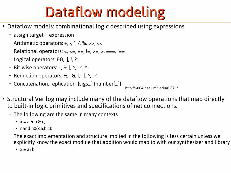
Dataflow modelingDataflow modeling● Dataflow models: combinational logic described using expressions
– assign target = expression– Arithmetic operators: +, -, *, /, %, >>, <<– Relational operators: <, <=, ==, !=, >=, >, ===, !==– Logical operators: &&, ||, !, ?:– Bit-wise operators: ~, &, |, ^, ~^, ^~– Reduction operators: &, ~&, |, ~|, ^, ~^– Concatenation, replication: {sigs…} {number{…}}
● Structural Verilog may include many of the dataflow operations that map directly to built-in logic primitives and specifications of net connections. – The following are the same in many contexts
● x = a & b & c;● nand n0(x,a,b,c);
– The exact implementation and structure implied in the following is less certain unless we explicitly know the exact module that addition would map to with our synthesizer and library
● x = a+b
http://6004.csail.mit.edu/6.371/

Dataflow VerilogDataflow Verilog
// 2-to-4 demultiplexer with active-low outputs// dataflow modelmodule demux2(a,b,enable,z); input a,b,enable; output [3:0] z;
assign z[0] = | {~enable,a,b}; //reduction operator assign z[1] = ~(enable & a & ~b); assign z[2] = ~(enable & ~a & b); assign z[3] = enable ? ~(a & b) : 1’b1; //conditional
// expression like Cendmodule

Behavioral Code and RTL CodeBehavioral Code and RTL Code● Behavioral code is implemented in procedural blocks that include one or several statements that
describe an algorithm to define the behavior of a block of logic in a simulation or in hardware● A procedural block may include sequential statements from which the algorithm may be understood by
beginning interpretation of statements one at a time (similar to traditional software coding languages) or parallel statements intended to be interpreted in parallel. – begin...end block include code with sequential statements – fork...join blocks include code with parallel statements
● The creation of behavioral code is sometimes characterized by a lack of regard for hardware realization● Synthesizable Behavioral Code is code that a given synthesizer can map to a hardware implementation
– The definition of synthesizable is synthesizer dependant- some simple prodecural code constructs are universally synthesizable by every synthesizer, while more complex code blocks and certain operators are not considered synthesizable by many
● Example: – x = myUINT8 >> 2;
● This is a shift by a constant implemented by a simple routing of bits. It is generally regarded as synthesizable– x = myUINT8 >> varShift;
● This is a variable shift with many possible implementations. It will simulate just fine, but at the synthesis step many synthesizers will throw an error saying that this is not synthesizable though it is ex
– Behavioral code may indeed describe behavior in such a way that is not directly synthesizable by almost any synthesizer (such as reading waveforms from a .txt file) – though what is “synthesizable” is always defined by the synthesizer tool being used
● Procedural code implemented with regard for hardware implementation, from which registers, the combinatorial logic between, and control signals like clocks may be inferred is called Register Transfer Level (RTL) code– Sometimes the terms “behavioral code” and “RTL code” are used in proximity to refer to synthesizable and non-
synthesizable code, though even this separation is dependent on the synthesizer tool being used

Initial and Always BlocksInitial and Always Blocks● Initial and Always blocks will be the first two types of blocks we will
discuss (tasks, functions)● Initial blocks are triggered once at the start of a simulation or in the
case of some synthesis tools may be used to describe the power-up state of registers or may be used to describe the initial default value of an intermediate variable
● Always blocks are triggered with every change in one or more signals as provided in a sensitivity list. – When describing combinatorial logic the sensitivity list should include
every input to the logic – For coding sequential logic the sensitivity list should include only the
control signals that trigger updates to sequential logic● Example Control signals to include in a sensitivity list for seq. logic blocks:
– enable for latches– clock for more traditional registers or flip-flops– any additional asynchronous controls like an asynchronous set and asynchronous reset

Behavioral Behavioral VerilogVerilog
Beginner's note
Here is something to be cleared up right away when learning Verilog “reg” is just a variable. In fact it is called a “variable” as of Verilog 2000 because the name is so confusing.So, don't be confused by it, “reg” is not necessarily register, They are used in behavioral descriptions as variables that may end up being implemented with if sequential logic is generated and are just represent the output net of combinatorial logic otherwise.Wires on the other hand are for structural connections (nets/wires) between modules or outputs of combinatorial expressions.
Thus we shall always refer to a statement
“reg y;” as “reg why” not “register why”
reg “register”
// 2-to-4 demultiplexer with active-low outputs// behavioral modelmodule demux3(a,b,enable,y); input a,b,enable; output [3:0] y; reg y; // not really a register! always @(a, b, enable) case ({enable,a,b}) default: y = 4'b1111; 3'b100: y = 4'b1110; 3'b110: y = 4'b1101; 3'b101: y = 4'b1011; 3'b111: y = 4'b0111; endcaseendmodule

Behavioral Behavioral VerilogVerilog
// 2-to-4 demultiplexer with active-low outputs// behavioral modelmodule demux3(a,b,enable,y); input a,b,enable; output [3:0] y; reg y; // not really a register! always @(a, b, enable) case ({enable,a,b}) default: y = 4'b1111; 3'b100: y = 4'b1110; 3'b110: y = 4'b1101; 3'b101: y = 4'b1011; 3'b111: y = 4'b0111; endcaseendmodule
Contents of “sensitivity list” needs careful attention. A bug here is a most common cause for diferences between Verilog simulation and synthesized hardware.
Since y is always assigned a value in thebody of the always block, it’s value doesn’t have to be remembered between executions.Therefore no state needs to be saved, i.e., no register needs to be created.

Sequential vs Combinatorial Logic in hardware synthesis Sequential vs Combinatorial Logic in hardware synthesis using always begin...end blocks (Rules of Thumb) using always begin...end blocks (Rules of Thumb)
● if you could ignore the sensitivity list and reevaluate the procedural block at any and every instant of time and there would be no change the overall interpretation of the algorithm then combinatorial hardware is described meaning it can be mapped to a set of output input relationships described by a combinatorial truth table and no memory of the past is required
● if the restriction of only allowing revaluation of the block contents when specific changes occur according to the sensitivity list would cause a difference in behavior at any point in time then sequential logic is described
● If results from any execution of the block directly rely on signals/results generated from a previous execution of the block then sequential logic is describe. This does not include the case when results are saved using external sequential logic.
● Draw the truth table for each block with and without considering the sensitivity list, it should include a row for every possible input combination and the output variables should should never occur in the output columns:
always @ (a,b,c) begin x = (c & a) | (~c & b);end
always @ (a,b,c) begin if c x = a; else x = b;end
always @ (a,c) begin x = (c & a) | (~c & x);end
always @ (c) begin if c x = a; else x = b;end

Viewing resultsViewing results
module main; reg a,b,enable; wire [3:0] s_z,d_z,b_z;
demux1 structural(a,b,enable,s_z); demux2 dataflow(a,b,enable,d_z); demux3 behavioral(a,b,enable,b_z); initial begin $dumpfile("demux.vcd"); //Specify file for
//Value Change Dump (VCD) info $dumpvars(1,main); enable = 0; a = 0; b = 0; //Force one last change
//at final time for better display #10 enable = 1; #10 a = 1; #10 a = 0; b = 1; #10 a = 1; #10 enable = 0; $finish; endendmodule
Code from the demux examples canbe found in /mit/6.371/examples/demux.vl
Dump variables in module main. First arg is # of levels to dump, eg, “2” would includevariables from modules instantiated by main.$dumpvars with no args will dump everything.

SimulatingSimulating● The stimulus (input)
– Designs can be instantiated and driven by other HDL code, typically called a testbench, that drives test signals
– Alternatively, some simulators support a scripting language to drive input signals
● The output– Use $display $monitor or $strobe statements to print result
to screen or file– Create a value change dump file (VCD)
● Can be read and displayed by many tools
– May Directly use a GUI to select and display signals
Design StrategiesDesign Strategies● For a beginner, treat Verilog as Hardware
Description Language, not a software coding language. Start off learning Verilog by describing hardware for which you can design and draw a schematic; then translate this to HDL.
● Plan by partitioning the design into sections and modules and coding styles that should be used.
● Identify existing modules, memory components needed, and data-path logic, as well as the control signals required to make those operate as desired.
● Simulate each part with a testbench before putting system together. Update testbenches and resimulate them as your design evolves.

● Large memory blocks are often provided by the manufacturer to be instantiated. Smaller memory elements may be coded or embedded into other descriptions of the design
● Data-path logic can be embedded coded with data-flow, structural elements, or complex synthesizable behavioral descriptions.
● Some styles explicitly separate Comb. Logic and Seq Logic, but this is up to you.
● Best practice is to develop a consistent approach to design, as well as a consistent coding style. It makes designing, coding, and debugging easier for you with time. An inconsistent hack-it-together and hack-until-it-works approach is not conducive to becoming more efficient.
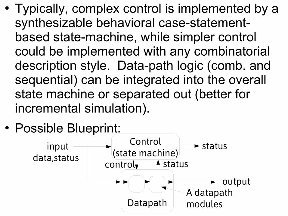
● Typically, complex control is implemented by a synthesizable behavioral case-statement-based state-machine, while simpler control could be implemented with any combinatorial description style. Data-path logic (comb. and sequential) can be integrated into the overall state machine or separated out (better for incremental simulation).
● Possible Blueprint:Control
(state machine)
Datapath
inputdata,status
output
control status
A datapathmodules
status

Components of a modeling/description languageComponents of a modeling/description language
● Wires and registers with specified precision and sign
● Arithmetic and bitwise operations
● Comparison Operations
● Bitvector Operations (selecting multiple bits from a vector, concatenation)
● Logical Operators
● Selection (muxes)
● Indexed Storage (arrays)
● Organizational syntax elements and Precedence
● Modules (Hardware) Definition and Instantiation

port list: ports must be declared to be input, output, or inout
port list: ports must be declared to be input, output, or inout
Additional internal netsmay be declared using the wire or reg word
Additional internal netsmay be declared using the wire or reg word
Modules and PortsModules and Ports
`timescale 1ns / 1ps//create a NAND gate out of an AND and an Invertermodule some_logic_component (c, a, b); // declare port signals output c; input a, b; // declare internal wire wire d; //instantiate structural logic gates and a1(d, a, b); //d is output, a and b are inputs not n1(c, d); //c is output, d is inputendmodule
keyword module begins a modulekeyword module begins a module
keyword endmodulebegins a modulekeyword endmodulebegins a module
nodes can be connectedto nested modules or primitivesor interact with procedural code
nodes can be connectedto nested modules or primitivesor interact with procedural code

Verilog 95 code
Verilog 2k with direction and data type listed
Verilog 2k with no type in port list
Verilog 2000: New Port Decl. OptionsVerilog 2000: New Port Decl. Options
module memory( input wire read, input wire write, input wire [7:0] data_in, input wire [3:0] addr, output reg [7:0] data_out);
module memory( input read, input write, input [7:0] data_in, input [3:0] addr, output reg [7:0] data_out);
module memory( read, write, data_in, addr, data_out);input read;input write;input [7:0] data_in;input [3:0] addr;output [7:0] data_out;
reg [7:0] data_out;
After the port list, port direction must be declared to be input, output, or inout as well as the width if more than one bitType declaration: type is by default a wire unless another type is provided
After the port list, port direction must be declared to be input, output, or inout as well as the width if more than one bitType declaration: type is by default a wire unless another type is provided
declared as wire by default
declared as wire by default

Verilog 2000 – port y as wire
Disadvantage to exposing type in port declarationDisadvantage to exposing type in port declaration
● module dff2y(output reg qA,output reg qB,output reg y,input dA,input dB,input en_n, input clk)
always@(posedge clk) if (~en_n) begin qA <= dA; qB <= dB; end
always @(qA,aB) begin y = 1’b0; if (a&b) begin y = 1; end endend
module dff2y(output reg qA,output reg qB,output wire y,input dA,input dB,input en_n, input clk)
always@(posedge clk) if (~en_n) begin qA <= dA; qB <= dB; end
assign y = qA&qB;end
Verilog 2000 – port y as reg
y is not the output of a register though declared as reg along with qA and qB in the left module declarationIt is arguable that such an internal codingimplementation detail does not belong in the presentation of an“external” interface
y is not the output of a register though declared as reg along with qA and qB in the left module declarationIt is arguable that such an internal codingimplementation detail does not belong in the presentation of an“external” interface
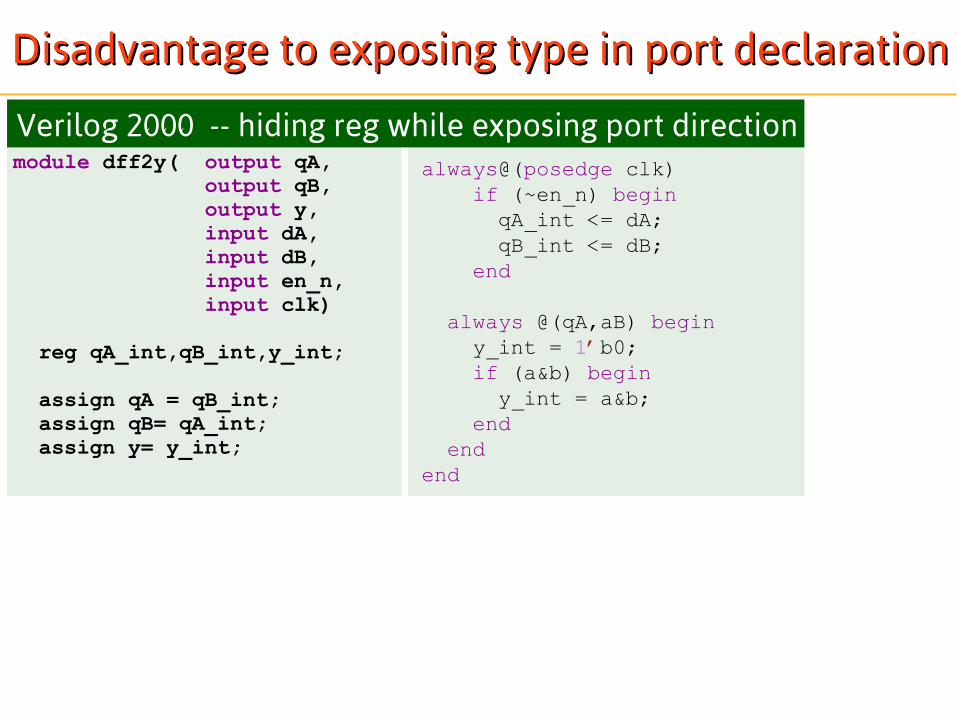
module dff2y( output qA,output qB,output y,input dA,input dB,input en_n, input clk)
reg qA_int,qB_int,y_int; assign qA = qB_int; assign qB= qA_int; assign y= y_int;
Verilog 2000 -- hiding reg while exposing port directionalways@(posedge clk) if (~en_n) begin qA_int <= dA; qB_int <= dB; end
always @(qA,aB) begin y_int = 1’b0; if (a&b) begin y_int = a&b; end endend
Disadvantage to exposing type in port declarationDisadvantage to exposing type in port declaration
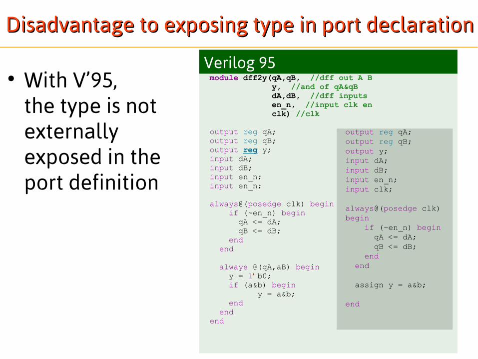
Verilog 95● With V’95,
the type is notexternally exposed in the port definition
module dff2y(qA,qB, //dff out A B y, //and of qA&qB
dA,dB, //dff inputs en_n, //input clk en
clk) //clk
output reg qA;output reg qB;output reg y; input dA;input dB;input en_n;input en_n;
always@(posedge clk) begin if (~en_n) begin qA <= dA; qB <= dB; end end
always @(qA,aB) begin y = 1’b0; if (a&b) begin
y = a&b; end endend
output reg qA;output reg qB;output y; input dA;input dB;input en_n;input clk;
always@(posedge clk) begin if (~en_n) begin qA <= dA; qB <= dB; end end
assign y = a&b;
end
Disadvantage to exposing type in port declarationDisadvantage to exposing type in port declaration

Hierarchy and InstantiationHierarchy and Instantiation
Instantiation with Implicit Port Mappingmodule dff2y_en( output qA, qB,
output y, input dA, dB, input en, input clk)
wire en_n = ~en;
dff2y dff2yInstance( qA,qB, //dff out A B y, //and of qA&qB dA,dB, //dff inputs en_n, //input clk en clk); //clkendmodule
wire en_n; assign en_n = ~en;
At this level of the hierarchy y is a wire regardless of the internal code implementation of y in dff2y
At this level of the hierarchy y is a wire regardless of the internal code implementation of y in dff2y
● Implicit port mapping uses the order of the ports in the definition to imply connections to local nets

Hierarchy and InstantiationHierarchy and Instantiation● Explicit port mapping uses the port names
prefixed with . and allows reordering, no-connect, and omission of ports
Instantiation with Explicit Port Mappingmodule dff2y_en( output y,
input dA, dB, input en, input clk)
dff2y dff2yInstance( .dA(dA), .dB(dB), .qA(), //qA not used (no-connect) //qB omitted .y(y), .en_n(~en), .clk(clk)); //clkendmodule
Implicit net declaration of a net holding the result ~en.This is NOT allowed if default net declaration is disabled. ie using`default net_type none
Implicit net declaration of a net holding the result ~en.This is NOT allowed if default net declaration is disabled. ie using`default net_type none

Delay statements use # and should be kept on separate on lines for nowDelay statements use # and should be kept on separate on lines for now
strictly internal nodesstrictly internal nodes
//test the NAND gatemodule test_bench; //module with no ports reg A, B; wire C; //instantiate your circuit some_logic_component dut1(C, A, B);
//Behavioral code block generates stimulus to test circuit initial begin A = 1'b0; B = 1'b0; #50 $display("A = %b, B = %b, Nand output C = %b \n", A, B, C); A = 1'b0; B = 1'b1; #50 $display("A = %b, B = %b, Nand output C = %b \n", A, B, C); A = 1'b1; B = 1'b0; #50 $display("A = %b, B = %b, Nand output C = %b \n", A, B, C); A = 1'b1; B = 1'b1; #50 $display("A = %b, B = %b, Nand output C = %b \n", A, B, C); endendmodule
A Testbench ModuleA Testbench Moduletypically no portstypically no ports
procedural code drives the stimulusto test the module under testprocedural code drives the stimulusto test the module under test
includes an instance of a module under testincludes an instance of a module under test

Sensitivity ListSensitivity List● Prev versions of Verilog used or keyword in sensitivity
list, which referred to a sensitivity to a change in any of a or b or c.
This is not the same as being sensitive to a change in the result (a|b|c).
● With Verilog 2001:– Use a comma-separated sensitivity list
– Shortcut for including all dependencies (inputs) in a combinatorial block:
always @ (a|b|c); //not the same
always @ (a or b or c)
always @ (a, b, c, d)always @ (posedge clk, posedge reset)
always @ (*)

Simple Testbench with a ClockSimple Testbench with a Clockmodule mydevice_tb(); reg clk, rst; reg x1, x2; wire y1, y2;
mydevice DUT(clk,rst, y1,y2, x1,x2);
initial clk = 0;
always begin #50; //delay clk = ~clk; end
initial begin #1000 $finish; end Stops simulation at T=1000Stops simulation at T=1000
many signals will be reg since they are driven by procedural codemany signals will be reg since they are driven by procedural code
An initial statement or block can set initial values of signalsAn initial statement or block can set initial values of signals
A always block with delays can be used to drivecyclic signals
A always block with delays can be used to drivecyclic signals
An instance of the device under testAn instance of the device under test
Outputs from the module under testare simply structural connections at this level so wires are used
Outputs from the module under testare simply structural connections at this level so wires are used

initial begin rst = 1; #10; //delay rst = 0; end
initial begin y1=0; y2=0;
#50; //delay y1=1; #50; //delay y1=0; y2=1; #50; //delay y1=1; y2=0; end
endmodule //end testbench module
Initial value and a change at T=10
Initial value and a change at T=10
Intialize signals immediately if not otherwise initialized, then add delays and assignments
We'll see other examples later, but at first avoid changing signals input to clockedblocks at the same time as the clock edge itis sensitive to
Intialize signals immediately if not otherwise initialized, then add delays and assignments
We'll see other examples later, but at first avoid changing signals input to clockedblocks at the same time as the clock edge itis sensitive to
This testbench includes no output statements, so it is assumed that a results waveform viewer (GUI) is usedThis testbench includes no output statements, so it is assumed that a results waveform viewer (GUI) is used

Numerical LiteralsNumerical Literals
2'b10 // 2 bit binary-specified number 'b10 // at least a 32-bit binary number 3 // at least a 32-bit decimal number 8'hAf // 8-bit hexadecimal-specified-16'd47 // 16-bit negative decimal-specified number
● Numerical Literals in Verilog are commonly provide use a format with '
● The size is always specified as a decimal number. If no size is specified then the default size is at least 32bits and may be larger depending on the machine. Valid base formats are 'b , 'B , 'h , 'H 'd , 'D , 'o , 'O for binary, hexadecimal, decimal, and octal. Numbers consist of strings of digits (0-9, A-F, a-f, x, X, z, Z). The x's mean undetermined, and the z's mean high-impedance If no base format is specified the number is assumed to be a decimal number. Some examples of valid numbers are:

Logical PrimitivesLogical Primitives● Here is a list of logic primitives defined for Verilog:
Gate Parameter List Examples
nand nor
and or xor
xnor
scalable, requires at least 2 inputs(output, input1, input2,... inputx)
and a1(C,A,B);nand na1(out1,in1,in2,in3,in4);
notbuf (output, input) not inv1(c,a);
notif0bufif0
control signal active low(output, input, control)
notif0 inv2(c,a, control);
notif1bufif1
control signal active high(output, input, control)
not inv1(c,a, control);
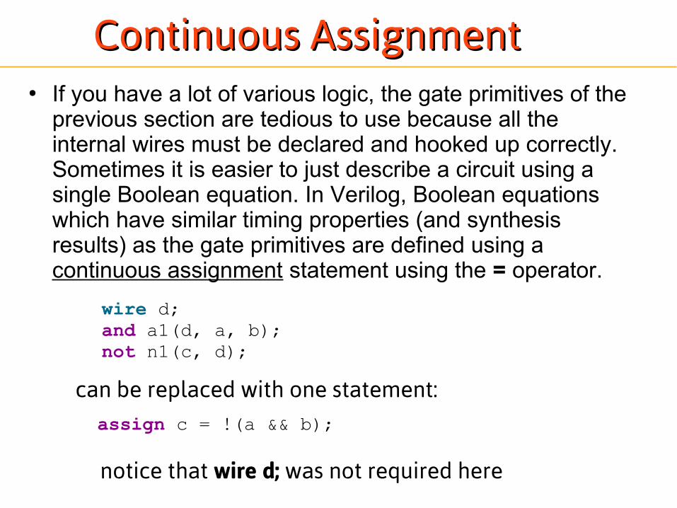
● If you have a lot of various logic, the gate primitives of the previous section are tedious to use because all the internal wires must be declared and hooked up correctly. Sometimes it is easier to just describe a circuit using a single Boolean equation. In Verilog, Boolean equations which have similar timing properties (and synthesis results) as the gate primitives are defined using a continuous assignment statement using the = operator.
wire d;and a1(d, a, b); not n1(c, d);
assign c = !(a && b);
can be replaced with one statement:
notice that wire d; was not required here
Continuous AssignmentContinuous Assignment

● Assignments can also be made during the declaration of a wire. In this case the assign keyword is implicitly assumed:
wire d;assign d = a || b; //continuous assignment
Implicit Continuous AssignmentImplicit Continuous Assignment
wire d = a || b; //implicit continuous assignment
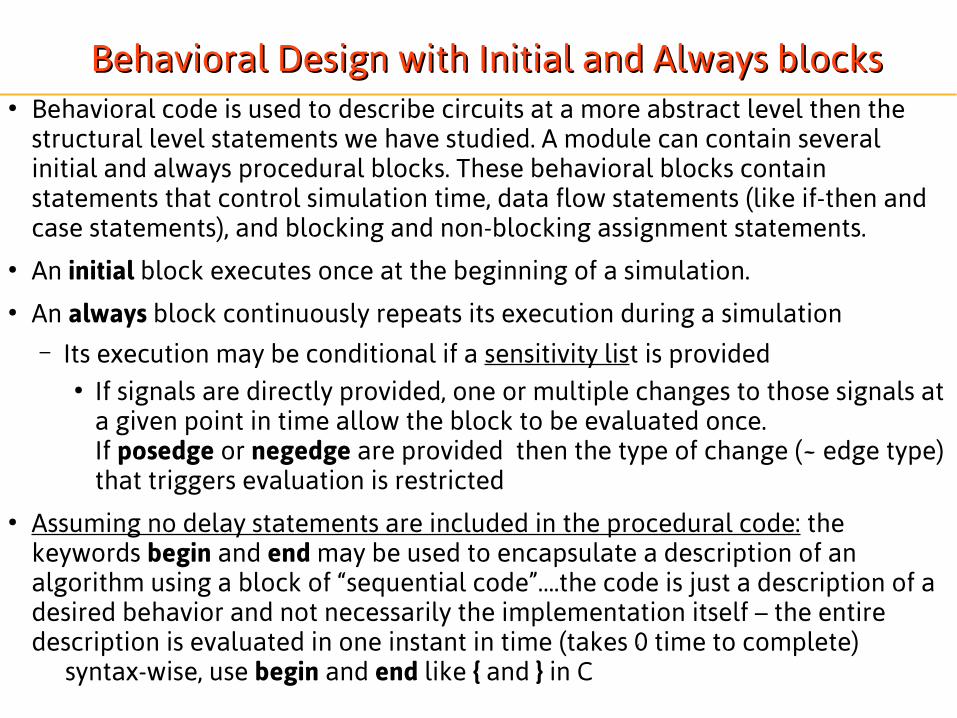
Behavioral Design with Initial and Always blocksBehavioral Design with Initial and Always blocks● Behavioral code is used to describe circuits at a more abstract level then the
structural level statements we have studied. A module can contain several initial and always procedural blocks. These behavioral blocks contain statements that control simulation time, data flow statements (like if-then and case statements), and blocking and non-blocking assignment statements.
● An initial block executes once at the beginning of a simulation.● An always block continuously repeats its execution during a simulation
– Its execution may be conditional if a sensitivity list is provided● If signals are directly provided, one or multiple changes to those signals at
a given point in time allow the block to be evaluated once. If posedge or negedge are provided then the type of change (~ edge type) that triggers evaluation is restricted
● Assuming no delay statements are included in the procedural code: the keywords begin and end may be used to encapsulate a description of an algorithm using a block of “sequential code”….the code is just a description of a desired behavior and not necessarily the implementation itself – the entire description is evaluated in one instant in time (takes 0 time to complete)
syntax-wise, use begin and end like { and } in C

Structural Data Types: Structural Data Types: wirewire and and regreg and the others and the others● Verilog data types called nets which model hardware connections between circuit
components. The two most common structural data types are wire and reg.
● A wire is like a real wire in a circuit . Its purpose is to make circuit network connections. Its value at every instant in time is decided by the driver connected to it. The driver may be assigned through a structural connection to a primitive or module or a continuous assignment statement.
● Module ports of type input and inout are always of type wire. This type decision is ignorant of the external connection driving the signal.
● Module ports of type output may be wire (network connection) or reg (a variable), depending on the coded driver. If driver is described using procedural code then use type reg.
● In procedural code, the reg type hold their values until another value is put on them.
● The declarations for wire and reg signals are inside a module but outside any initial or always block.
● The default state of a reg is 'x' (unknown), and the for a wire is 'z'.
● If you need a special strength type operation use special net keyword wand, wor, tri, triand, trior, trireg.

Undeclared NetsUndeclared Nets
wire a,b,c,d,y;mylib_and2(w1,a,b);mylib_and2(w2,c,d);mylib_and2(y,w1,w2);
•In Verilog 1995, default data type is net and its width is always 1 bit.•This can be dangerous for two reasons…
•a simple typing mistake can declare a new variable instead of an intended connection to an existing net causing a confusing error message or lead to a coding mistake•forgetting a declaration can lead to 1-bit wires which loose information
wire [7:0] a; wire [7:0] b; wire [7:0] d; wire [7:0] e; c=a+b; //one bit!!!! e=c+d;• In Verilog 2001 the width is adjusted automatically• In Verilog 2001, we can disable default data type by using a special directive at the top of the code: `default net_type none
Verilog 2000: Verilog 2000: signed reg type, reg init., new operatorssigned reg type, reg init., new operators
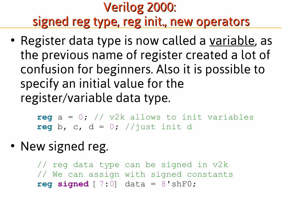
● Register data type is now called a variable, as the previous name of register created a lot of confusion for beginners. Also it is possible to specify an initial value for the register/variable data type.
● New signed reg.
reg a = 0; // v2k allows to init variablesreg b, c, d = 0; //just init d
// reg data type can be signed in v2k// We can assign with signed constantsreg signed [7:0] data = 8'shF0;

Behavioral Design with blocking and Behavioral Design with blocking and non-blocking assignment statementsnon-blocking assignment statements
● There are 2 kinds of assignment statements: – blocking using the = operator, and – non-blocking using the <= operator.
● Blocking assignments act like sequential code statements and make an assignment when they are encountered
● Non-blocking schedule assignments to happen at some time in the future. They are called non-blocking because statements the follow can be evaluated before the actual assignment happens.
● Here are some examples:

Beginner Tips for Procedural CodeBeginner Tips for Procedural Code
1. When modeling sequential logic, use non-blocking assignments. registerA <= b+c;
2. When modeling latches, use non-blocking assignments. (actually don't code any latches for now. If you see any synthesis message for latches, eliminate them.)
3. When modeling combinatorial logic with an always block, use blocking assignments. a=b+c;
4. Separate combinatorial and sequential logic into separate always blocks (as much as reasonably possible) to avoid accidental registers and latches.
5. When modeling both sequential and combinatorial logic within the same always block, use non-blocking assignments for registers and minimally use blocking statements for intermediate combinatorial logic.
6. Do not mix blocking and non-blocking assignments to the same variable in the same always block.
7. Do not make assignments to the same variable from more than one always block.
http://www.sunburst-design.com/papers/

Good, uses Non-blocking Assignment
Guideline: Use non-blocking assignment Guideline: Use non-blocking assignment for for EVERYEVERY output of a register output of a register
module dffx (q, d, clk, rst); output q; input d, clk, rst; reg q; always @(posedge clk) if (rst) q <= 1'b0; else q <= d;endmodule
module dffb (q, d, clk, rst); output q; input d, clk, rst; reg q; always @(posedge clk) if (rst) q = 1'b0; else q = d;endmodule
coding all sequential always blocks, even simple single-block modules, using nonblocking assignments.
coding all sequential always blocks, even simple single-block modules, using nonblocking assignments.
Poor, uses blocking Assignment

Combinatorial
Combinatorial and Registered-Output LogicCombinatorial and Registered-Output Logic
reg q;always @(posedge clk) q <= a & b;
In this isolated block you might have have also used y<= a & b;but we will follow a convention explained later whereby we use blocking for all combinatorial logic
reg y;always @(a,b) y = a & b;
Sequential (registered-output combinatorial logic):

Three behavioral code organizations Three behavioral code organizations for sequential and combinatorial for sequential and combinatorial
logic with logic with 1) Separate always blocks for combinatorial and sequential logic
● Comb. assignments use blocking statements● Seq. assignments use non-blocking statements
2) Sequential and combinatorial logic in same block with combinatorial logic embedded in sequential assignments● Seq. assignments use non-blocking statements
3) Sequential and combinatorial logic in same block with both combinatorial and sequential assignments● Comb. assignments use blocking statements● Seq. assignments use non-blocking statements
Explicit Mix of Combinatorial and Sequential Logic”
Implicit Mix of Combinatorial and Sequential Logic:
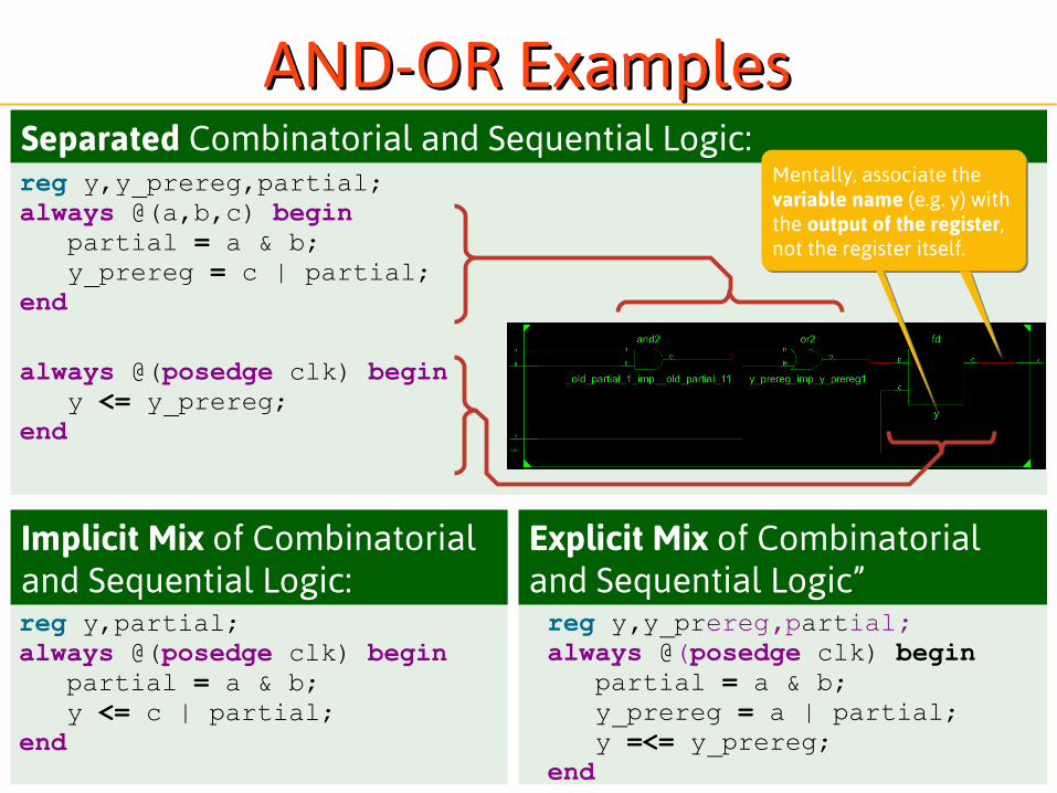
AND-OR ExamplesAND-OR Examples
reg y,partial;always @(posedge clk) begin partial = a & b; y <= c | partial;end
reg y,y_prereg,partial;always @(posedge clk) begin partial = a & b; y_prereg = a | partial; y =<= y_prereg;end
reg y,y_prereg,partial;always @(a,b,c) begin partial = a & b; y_prereg = c | partial;end
always @(posedge clk) begin y <= y_prereg;end
Separated Combinatorial and Sequential Logic:Mentally, associate the variable name (e.g. y) with the output of the register,not the register itself.
Mentally, associate the variable name (e.g. y) with the output of the register,not the register itself.

Separated Combinatorial and Sequential Logic:
AND-OR Examples with AND-OR Examples with async active low clr signalasync active low clr signal
reg y,y_prereg,partial;always @(a,b,c) begin partial = a & b; y_prereg = a | partial;end
always @(posedge clk, negedge clr_n) begin if (!clr_n) y <= 1'b0; else y <= y_prereg;
end
Asynchronous control signals must appear in the sensitivity listAsynchronous control signals must appear in the sensitivity list

Language TemplatesLanguage Templates● Typically Templates can be found in a
synthesizer manual or through the development GUI
(1) Click Lightbulb
(2) Navigate Tree
(3) View Template
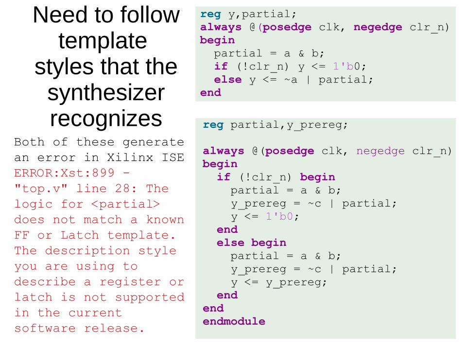
reg y,partial;always @(posedge clk, negedge clr_n) begin partial = a & b; if (!clr_n) y <= 1'b0; else y <= ~a | partial;end
Both of these generate an error in Xilinx ISEERROR:Xst:899 - "top.v" line 28: The logic for <partial> does not match a known FF or Latch template. The description style you are using to describe a register or latch is not supported in the current software release.
reg partial,y_prereg;
always @(posedge clk, negedge clr_n)begin if (!clr_n) begin partial = a & b; y_prereg = ~c | partial; y <= 1'b0; end else begin partial = a & b; y_prereg = ~c | partial; y <= y_prereg; endendendmodule
Need to follow template
styles that the synthesizer recognizes

reg y,y_prereg,partial;always @(posedge clk, negedge clr_n)begin if (!clr_n) y <= 1'b0; else begin partial = a & b; y_prereg = ~a | partial; y <= y_prereg; endend
implied registers and latchesare trimmed since they are only used inside this procedural codeblock and feed into another signal
If the are used outside, additional sequential logic would be generate to provide the saved values externally
implied registers and latchesare trimmed since they are only used inside this procedural codeblock and feed into another signal
If the are used outside, additional sequential logic would be generate to provide the saved values externally
WARNING:Xst:646 - Signal <y_prereg> is assigned but never used. This unconnected signal will be trimmed during the optimization process.WARNING:Xst:646 - Signal <partial> is assigned but never used. This unconnected signal will be trimmed during the optimization process.
The following code is more compact than the initial separated version, but leads to warnings

reg y,y_prereg,partial;always @(posedge clk, negedge clr_n)begin: blockY if (!clr_n) y <= 1'b0; else begin partial = a & b; y_prereg = ~a | partial; y <= y_prereg; endend
implied registers and latchesare trimmed since they are only used inside this procedural codeblock and feed into another signal
If the are used outside, additional sequential logic would be generate to provide the saved values externally
implied registers and latchesare trimmed since they are only used inside this procedural codeblock and feed into another signal
If the are used outside, additional sequential logic would be generate to provide the saved values externally
The following code is more compact than the initial separated version, but leads to warnings
•The warning tells us that these are not used externally to the procedural block and so they are trimmed-- we’ll call this a trimmable implementation and I allow it even though beginners probably should avoid this style.
end-triggered always block
partial
b
a
a
y_preregy
same as ysame as y

Trimmable StyleTrimmable Style● If you follow our coding guidelines, you must use
blocking assignment for outputs of combinatorial logic even if within edge-triggered procedural blocks.
● Any signal – 1. assigned by a non-block assignment AND– 2. assigned withing an edge triggered block
should be considered as an internal net and you should not (AND MAY NOT FOR THIS COURSE) use that net outside the block in which it is assigned
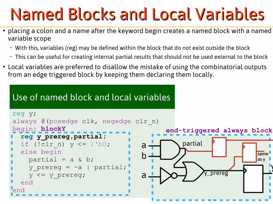
Named Blocks and Local VariablesNamed Blocks and Local Variables● placing a colon and a name after the keyword begin creates a named block with a named
variable scope– With this, variables (reg) may be defined within the block that do not exist outside the block – This can be useful for creating internal partial results that should not be used external to the block
● Local variables are preferred to disallow the mistake of using the combinatorial outputs from an edge triggered block by keeping them declaring them locally.
reg y;always @(posedge clk, negedge clr_n)begin: blockY reg y_prereg,partial; if (!clr_n) y <= 1'b0; else begin partial = a & b; y_prereg = ~a | partial; y <= y_prereg; endend
Use of named block and local variables
end-triggered always block
partial
b
a
a
y_preregy
same as ysame as y
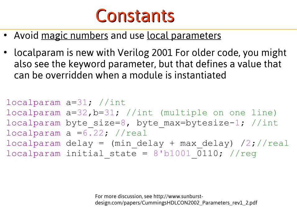
ConstantsConstants● Avoid magic numbers and use local parameters
● localparam is new with Verilog 2001 For older code, you might also see the keyword parameter, but that defines a value that can be overridden when a module is instantiated
localparam a=31; //intlocalparam a=32,b=31; //int (multiple on one line)localparam byte_size=8, byte_max=bytesize-1; //intlocalparam a =6.22; //reallocalparam delay = (min_delay + max_delay) /2;//reallocalparam initial_state = 8'b1001_0110; //reg
For more discussion, see http://www.sunburst-design.com/papers/CummingsHDLCON2002_Parameters_rev1_2.pdf

Arrays, Vectors, and MemoriesArrays, Vectors, and Memories
● Verilog supports three similar data structures called Arrays, Vectors, and Memories. – Arrays are used to hold several objects of the same
type. – Vectors are used to represent multi-bit busses.– Memories are arrays of vectors which are accessed
similar to hardware memories.
● Read the following examples to determine how to reference and use the different data structures.

..arrays..arrays
// Arrays for integer, time, reg, and vectors of reg
integer i[3:0]; //integer array with a length of 4time x[20:1]; //time array with length of 19reg r[7:0]; //scalar reg array with length of 8
c = r[3]; //the 3rd reg value in array r is assigned to c
● Standard arrays defined by a high to low index are created with square brackets and colon following the identifier– <type> id[<HighBit>:<LowBit>];
● They are accessed using square brackets

...vectors...vectors
reg [7:0] MultiBitWord1; // 8-bit reg vector with MSB=7 LSB=0wire [0:7] MultiBitWord2; // 8-bit wire vector with MSB=0 LSB=7reg [3:0] bitslice;reg a; // single bit vector often referred to as a scalar
//referencing vectors
....
a = MultiBitWord1[3]; //applies the 3rd bit of MultiBitWord1 to abitslice = MultiBitWord1[3:0]; // applies the 3-0 bits of
// MultiBitWord1 to bitslice
● Vectors are multi-bit words of type reg or net
● Standard bit vectors defined by a high to low index are created with square brackets and colon preceding the identifier– <type> [<HighBit>:<LowBit>] id;
● They are accessed using square brackets for single bits and additionally using a colon if accessing a slice of bits

.. and “memories”.. and “memories”
reg [7:0] ram[0:4095]; // 4096 memory cells that are 8 bits wide
//code excerpt from Chapter 2 SRAM modelinput [11:0] ABUS; // 12-bit address bus to access all 4096 memory cellsinout [7:0] DATABUS;// 8-bit data bus to write into and out of a memory cellreg [7:0] DATABUS_driver;wire [7:0] DATABUS = DATABUS_driver; //inout must be driven by a wire....for (i=0; i <= 4095; i = i + 1) // Setting individual memory cells to 0 ram[i] = 0;end....ram[ABUS] = DATABUS; //writing to a memory cell....DATABUS_driver = ram[ABUS]; //reading from a memory cell
● Standard memories vectors defined using both bit vector and object array notation– <type> [<HighBit>:<LowBit>] id [<HighAddress>:<LowAddress>];
● The object (e.g. words) can be accessed like this:– id[address]
● Individual bit slices can be accessed like this (at least in newer versions of verilog):– id[address][highbit:lowbit]
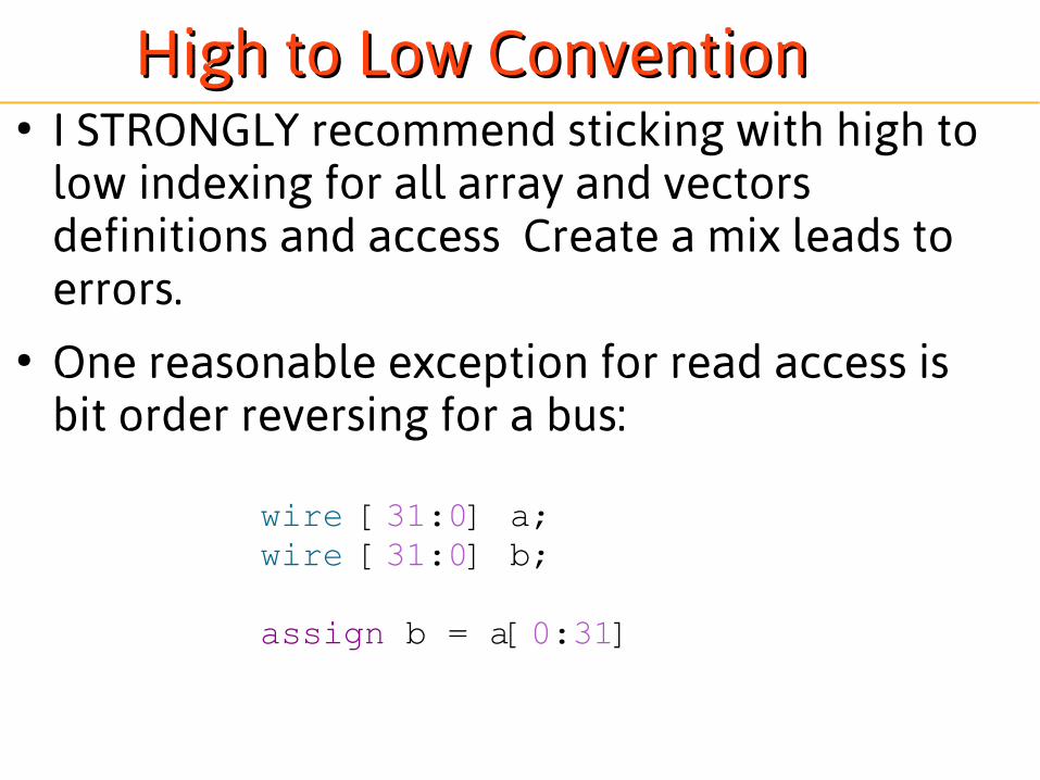
High to Low ConventionHigh to Low Convention● I STRONGLY recommend sticking with high to
low indexing for all array and vectors definitions and access Create a mix leads to errors.
● One reasonable exception for read access isbit order reversing for a bus:
wire [31:0] a;wire [31:0] b;
assign b = a[0:31]

OperatorsOperators● Here is a small selection of the Verilog Operators
which look similar but have different effects. ● Logical Operators evaluate to TRUE or FALSE. ● Bitwise operators act on each bit of the operands
to produce a multi-bit result. ● Unary Reduction operators perform the
operation on all bits of the operand to produce a single bit result.
● See also– http://www.asic-world.com/verilog/operators1.html
– http://www.asic-world.com/verilog/operators2.html

Operator Name Examples
! logical negation
~ bitwise negation
&& logical and
& bitwise and abus = bbus&cbus;
& reduction and abit = &bbus;
~& reduction nand
|| logical or
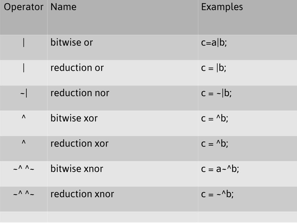
Operator Name Examples
| bitwise or c=a|b;
| reduction or c = |b;
~| reduction nor c = ~|b;
^ bitwise xor c = ^b;
^ reduction xor c = ^b;
~^ ^~ bitwise xnor c = a~^b;
~^ ^~ reduction xnor c = ~^b;

Operator Name, Description Examples
== logical equality, result may be unknown if x or z in the input
if (a == b)
=== logical equality including x and z
!= logical inequality, result may be unknown if x or z in the input
!== logical inequality including x and z
> relational greater than
>>,<< shift right or left by a number of positions a = shiftvalue >> 2;
>= relational greater than or equal
< relational less than
<<<,>>> Signed shifts, shift right or left by a number of positions with a signed left argument
<= relational less than or equal if (a <= b)
+,-,*,/ Arithmetic OperatorsNote: synthesizers may only support divide by constant power of two
c=a+b;c=b/4; //right shift by 2
** power c=a**b
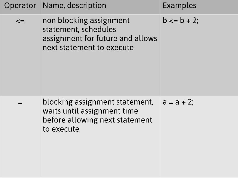
Operator Name, description Examples
<= non blocking assignment statement, schedules assignment for future and allows next statement to execute
b <= b + 2;
= blocking assignment statement, waits until assignment time before allowing next statement to execute
a = a + 2;
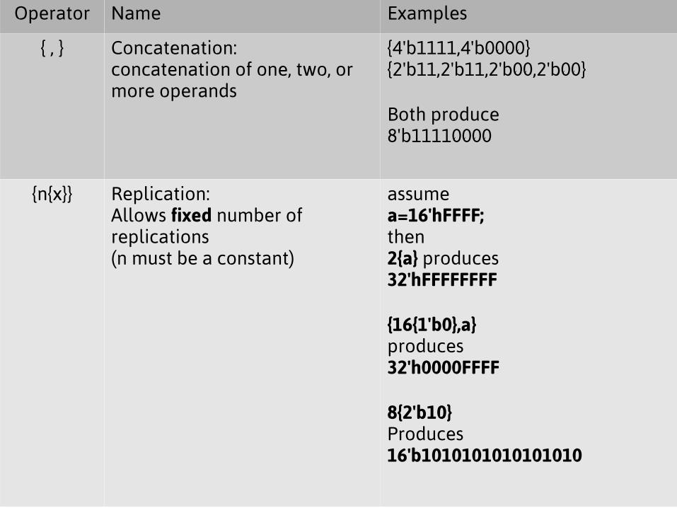
Operator Name Examples
{ , } Concatenation:concatenation of one, two, or more operands
{4'b1111,4'b0000}{2'b11,2'b11,2'b00,2'b00}
Both produce8'b11110000
{n{x}} Replication:Allows fixed number of replications (n must be a constant)
assumea=16'hFFFF;then2{a} produces32'hFFFFFFFF
{16{1'b0},a}produces32'h0000FFFF
8{2'b10}Produces16'b1010101010101010

Some additional Behavioral Data Types: Some additional Behavioral Data Types: integer, real, and timeinteger, real, and time
● The types in integer and real are convenient data types to use for counting in behavioral code blocks. These data types act like their counterparts in other programming languages. If you eventually plan to synthesize your behavioral code then you would probably want to avoid using these data types because they often synthesize large circuits.
● The data type time can hold a special simulator value called simulation time which is extracted from the system function $time. The time information can be used to help you debug your simulations.
integer i, y;real a;real b = 3.5;real c = 4;time simulationTime;initial begin y = 4; i = 5 + y; c = c + 3.5; a = 5.3e4; simulationTime = $time; $display("integer y = %d, i = %f \n", y, i); $display("reals c = %f, a = %e, b= %g \n", c, a, b); $display("time simulationTime = %t \n", simulationTime);end

Verilog Design FlowVerilog Design Flow● Create RTL Design Models and Behavioral Test
Bench Code● Functionally Simulate your Register-Transfer-
Level Design● Convert RTL-level files to a Gate-level model
with a Synthesizer● Perform Gate Level simulations with FPGA or
ASIC libraries● Optional Step: Gate-level simulation with SDF
timing information (with results from place and route)