introduction to telecommunications and computer … text, numbers, pictures, sound, or video—or...
TRANSCRIPT
Introduction to Telecommunications
and Computer EngineeringUnit 3: Communications Systems & Signals
Syedur RahmanLecturer, CSE Department
North South [email protected]

Acknowledgements
These notes contain material from the following sources:
[1] Data Communications and Networking, by
B.A.Forouzan, McGraw Hill, 2003.
[2] Communication Systems, by R.Palit, CSE
Department, North South University, 2006.
[3] Electromagnetic Spectrum and Harmonics,
Wikipedia the Free Encyclopedia,
www.wikipedia.org, 2007.

Basic Definitions
Communication can be defined as the successful
transmission of information through a common system of
symbols, signs, behavior, speech, writing, or signals.
Telecommunication refers to the communication of
information at a distance. This covers many technologies
including radio, telegraphy, television, telephone, data
communication and computer networking.
Telecommunication can be point-to-point, point-to-
multipoint or broadcasting,

Model of Communication System
Information
source and
input transducer
Transmitter
Output
TransducerReceiver
Channel
Output
Signal
Functional Block Diagram of a Communication System
Fundamental Characteristics of
a Communication System
1. Delivery - The system must deliver data to the correct
destination.
2. Accuracy - The system must deliver the data
accurately.
3. Timeliness - The system must deliver data in a timely
manner.
In the case of video and audio, timely delivery means delivering data
as they are produced, in the same order that they are produced, and
without significant delay. This kind of delivery is called real-time
transmission.
Components of Communication systems
1. Message - the information (data) to be communicated. It can consist of text, numbers, pictures, sound, or video—or any combination of these.
2. Sender - the device that sends the data message. It can be a computer, workstation, telephone handset, video camera, and so on.
3. Receiver - the device that receives the message. It can be a computer, workstation, telephone handset, television, and so on.
4. Medium - the physical path by which a message travels from sender to receiver. It could be a twisted-pair wire, coaxial cable, fiber optic cable, or radio waves (terrestrial or satellite microwave).
5. Protocol - a set of rules that governs data communications. It represents an agreement between the communicating devices. Without a protocol, two devices may be connected but not communicating.
Modes of Communication
�Simplex transmission - signals are transmitted
in only one direction; one station is transmitter
and the other is receiver.
�Half-duplex transmission - both stations may
transmit, but only one at a time
�Full-duplex transmission - both stations may
transmit simultaneously
Types of Data
Data (pieces of information) can be analog or digital
�Analog data take on the continuous values in some
interval. An example of analog data is the human
voice.
�Digital data take on discrete values; examples are
text and integers. Digital data is data stored in the
memory of a computer in the form of 0s and 1s.

Signals
Signals are electric or electromagnetic representation of data.
Signaling is the physical propagation of the signal along a suitable
medium. Transmission is the communication of data by the
propagation and processing of signals.
From [1]
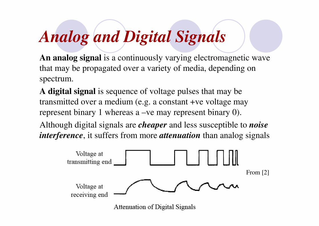
Analog and Digital SignalsAn analog signal is a continuously varying electromagnetic wave
that may be propagated over a variety of media, depending on
spectrum.
A digital signal is sequence of voltage pulses that may be
transmitted over a medium (e.g. a constant +ve voltage may
represent binary 1 whereas a –ve may represent binary 0).
Although digital signals are cheaper and less susceptible to noise
interference, it suffers from more attenuation than analog signals
From [2]
Periodic and Aperiodic Signals
A periodic signal completes a pattern within a
measurable time frame, called a period, and repeats that
pattern over subsequent identical periods. The completion
of one full pattern is called a cycle.
An aperiodic signal changes without exhibiting a pattern
or cycle that repeats over time.
Both analog and digital signals can be periodic or
aperiodic. In data communication, however, we
commonly use periodic analog signals and aperiodic
digital signals to send data from one point to another.

Analog Signals – A sine wave
We can mathematically describe a sine wave as
s(t) = A sin(2ππππ f t + θ)
Where s is the instantaneous amplitude, A the peak
amplitude, f the frequency, and θ the phase
These last three characteristics fully describe a sine wave.
From [1]

Characteristics of a Sine Wave
From [1]
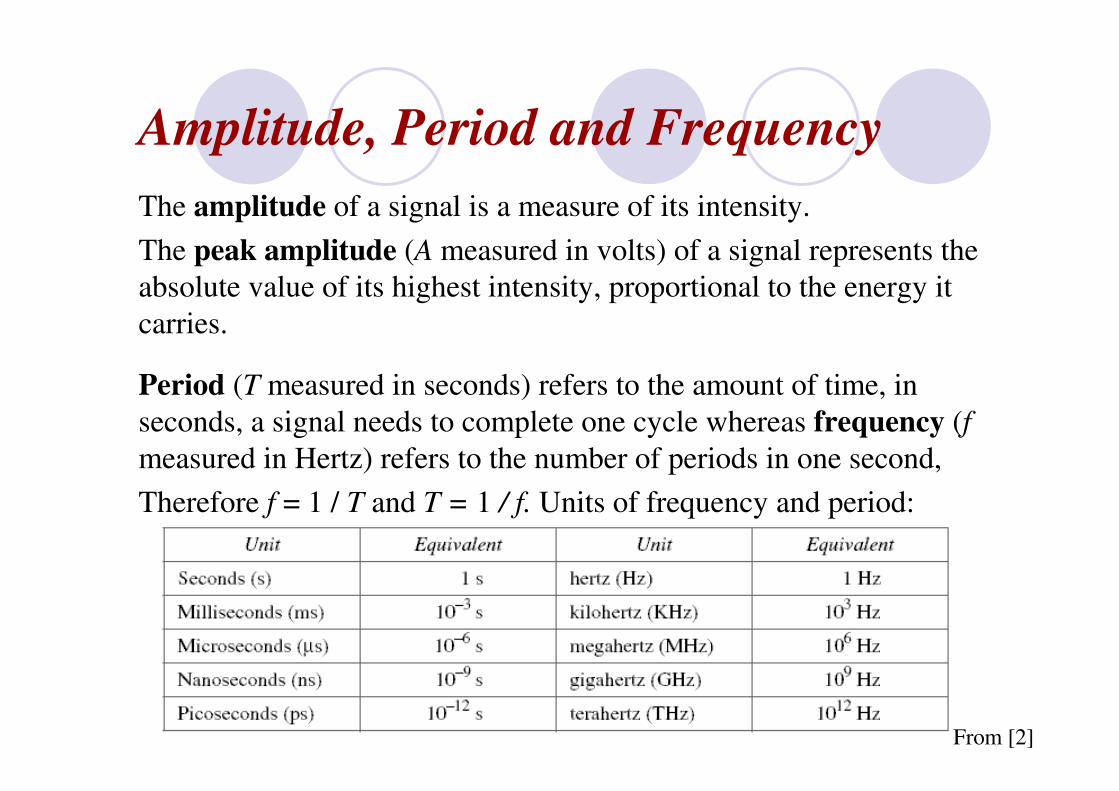
Amplitude, Period and Frequency
The amplitude of a signal is a measure of its intensity.
The peak amplitude (A measured in volts) of a signal represents the
absolute value of its highest intensity, proportional to the energy it
carries.
Period (T measured in seconds) refers to the amount of time, in
seconds, a signal needs to complete one cycle whereas frequency (f
measured in Hertz) refers to the number of periods in one second,
Therefore f = 1 / T and T = 1 / f. Units of frequency and period:
From [2]

Phase (difference)
Phase describes the position of the waveform relative to time
zero. Phase is measured in degrees or radians [360°is 2π rad;
1°is π/180 rad, and 1 rad is 180°].
A phase shift of 360°corresponds to a shift of a complete period; a phase shift of
180°corresponds to a shift of one-half of a period; and a phase shift of 90°
corresponds to a shift of one-quarter of a period
From [2]

Time Domain Plots
These plot instantaneous amplitude with respect to frequency
Remember:
s(t) =
A sin(2ππππ f t + θ)
From [1]

Composite Signals & Fourier Analysis
A single-frequency sine wave is not useful in data
communications; to make it useful we need to change one or
more of its characteristics, thereby making it a composite
signal.
According to Fourier analysis, any composite signal can be
represented as a combination of simple sine waves with
different frequencies, phases, and amplitudes. i.e. we can write
a sine-wave as
From [1]
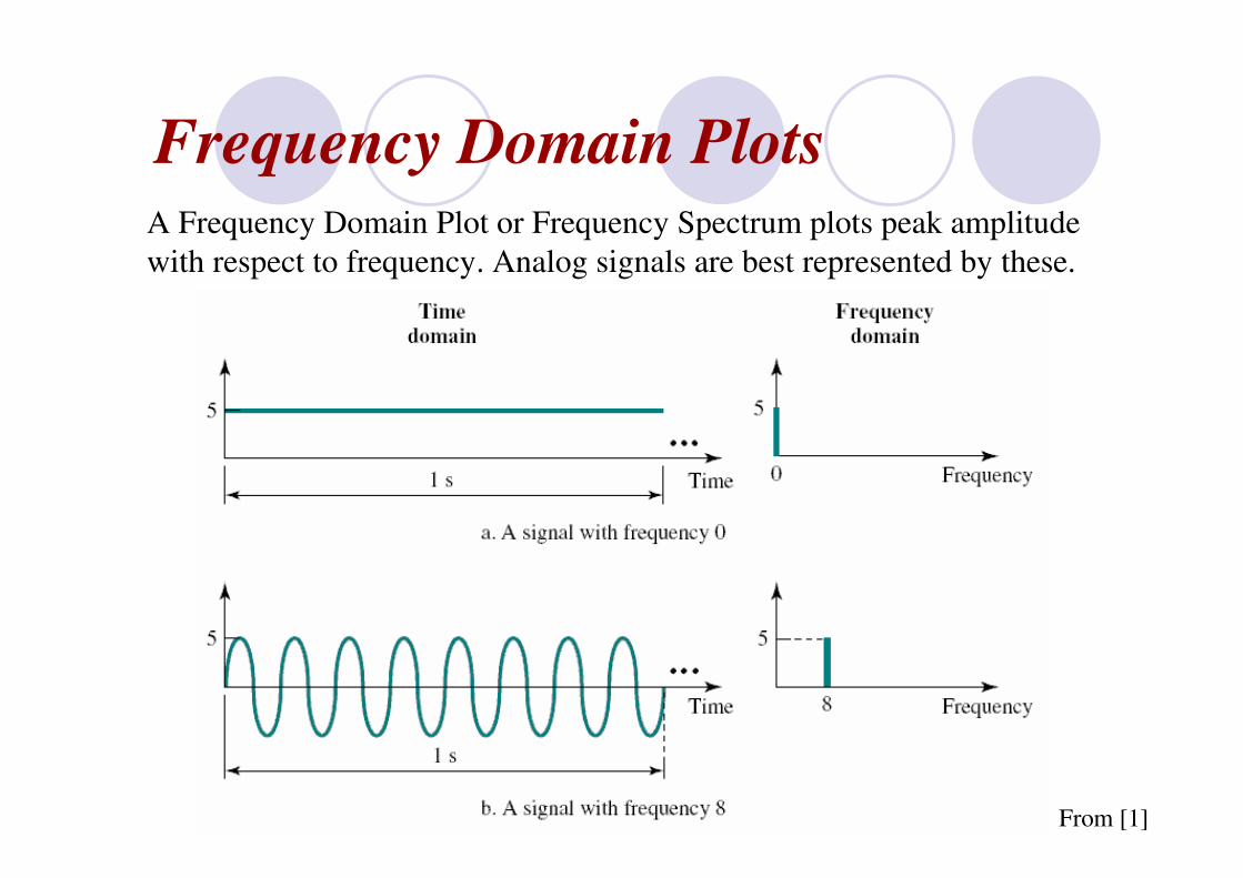
Frequency Domain PlotsA Frequency Domain Plot or Frequency Spectrum plots peak amplitude
with respect to frequency. Analog signals are best represented by these.
From [1]
Example Frequency Domain Plot
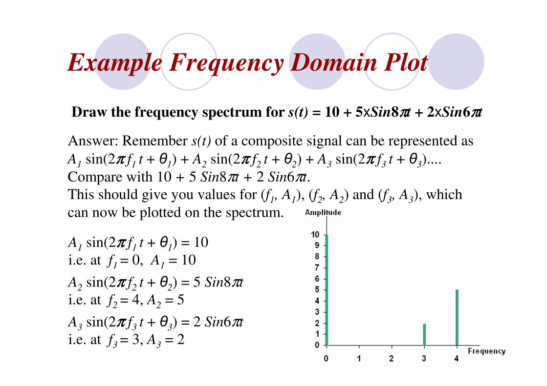
Draw the frequency spectrum for s(t) = 10 + 5xSin8ππππt + 2xSin6ππππt
Answer: Remember s(t) of a composite signal can be represented as
A1 sin(2ππππ f1 t + θ1) + A2 sin(2ππππ f2 t + θ2) + A3 sin(2ππππ f3 t + θ3)....
Compare with 10 + 5 Sin8πt + 2 Sin6πt.
This should give you values for (f1, A1), (f2, A2) and (f3, A3), which
can now be plotted on the spectrum.
A1 sin(2ππππ f1 t + θ1) = 10
i.e. at f1 = 0, A1 = 10
A2 sin(2ππππ f2 t + θ2) = 5 Sin8πt
i.e. at f2 = 4, A2 = 5
A3 sin(2ππππ f3 t + θ3) = 2 Sin6πt
i.e. at f3 = 3, A3 = 2

Fundamental Frequency and Harmonics
When you have a composite wave with the equation s(t) = A1 sin(2ππππ f t + θ1) + A2 sin(2ππππ 2f t + θ2) + A3 sin(2ππππ 3f t + θ3)....
the first basic wave with frequency f is called the first
harmonic or the fundamental frequency. The one with
frequency 2f is the second harmonic or the first overtone
and so on. Overtones whose frequency is not an integer
multiple of the fundamental are called inharmonic.
An example involving musical instruments
fourth harmonicthird overtone1760 Hz4f
third harmonicsecond overtone1320 Hz3f
second harmonicfirst overtone880 Hz2f
first harmonicfundamental frequency440 Hz1f

Fourier Analysis of a Square Wave
According to Fourier analysis, we can prove that this signal can be
decomposed into a series of sine waves as shown below.
We have a series of sine waves with frequencies f, 3f, 5f, 7f, . . . and
amplitudes 4A/π, 4A/3π, 4A/5π, 4A/7π, and so on. The term with frequency f is
dominant and is called the fundamental frequency. The term with frequency
3f is called the third harmonic, the term with frequency 5f is the fifth
harmonic, and so on.
From [1]

Adding Harmonics
If we add these three
harmonics, we do not
get a square wave—
we get something
which is close, but
not exact. For
something more
exact we need to add
more harmonics
Three separate harmonics
After adding three harmonics
From [1]
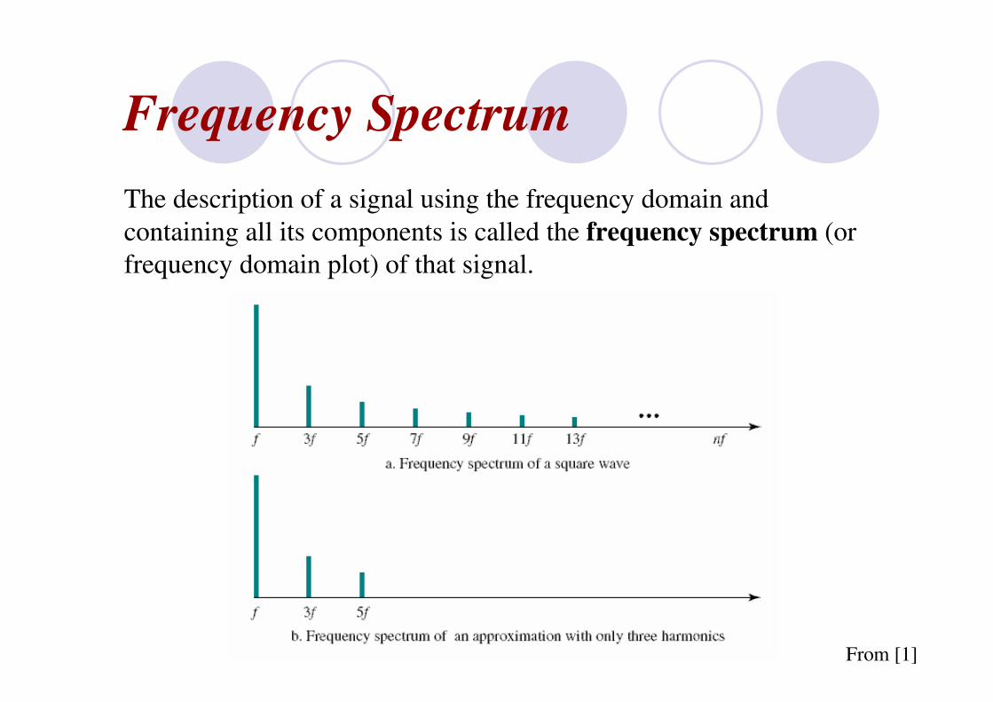
Frequency Spectrum
The description of a signal using the frequency domain and
containing all its components is called the frequency spectrum (or
frequency domain plot) of that signal.
From [1]
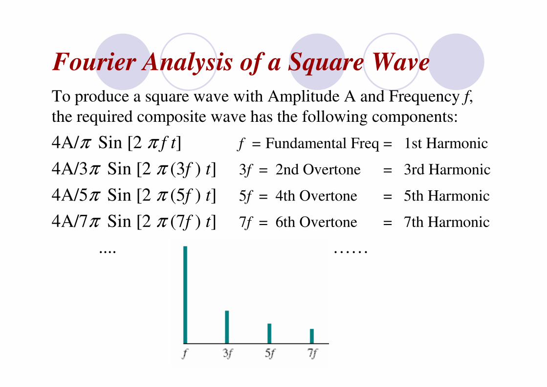
Fourier Analysis of a Square Wave
To produce a square wave with Amplitude A and Frequency f,
the required composite wave has the following components:
4A/π Sin [2 π f t] f = Fundamental Freq = 1st Harmonic
4A/3π Sin [2 π (3f ) t] 3f = 2nd Overtone = 3rd Harmonic
4A/5π Sin [2 π (5f ) t] 5f = 4th Overtone = 5th Harmonic
4A/7π Sin [2 π (7f ) t] 7f = 6th Overtone = 7th Harmonic
.... ……

An Example - A square wave with amplitude 10V and frequency
20Hz produced using 5 harmonics has the following components:
4A/π Sin [2 π f t] A1 = 4x10/π = 12.70 f1 = 20Hz
4A/3π Sin [2 π (3f ) t] A2 = 4x10/3π = 4.24 f2 = 60Hz
4A/5π Sin [2 π (5f ) t] A3 = 4x10/5π = 2.55 f3 = 100Hz
4A/7π Sin [2 π (7f ) t] A4 = 4x10/7π = 1.82 f4 = 140Hz
4A/9π Sin [2 π (9f ) t] A5 = 4x10/9π = 1.41 f5 = 180Hz
Frequency Domain Plot for Desired Square Wave
An Example - A square wave with amplitude 10V and frequency
20Hz produced using 5 harmonics has the following components:
4A/π Sin [2 π f t] A1 = 4x10/π = 12.70 f1 = 20Hz
4A/3π Sin [2 π (3f ) t] A2 = 4x10/3π = 4.24 f2 = 60Hz
4A/5π Sin [2 π (5f ) t] A3 = 4x10/5π = 2.55 f3 = 100Hz
4A/7π Sin [2 π (7f ) t] A4 = 4x10/7π = 1.82 f4 = 140Hz
4A/9π Sin [2 π (9f ) t] A5 = 4x10/9π = 1.41 f5 = 180Hz
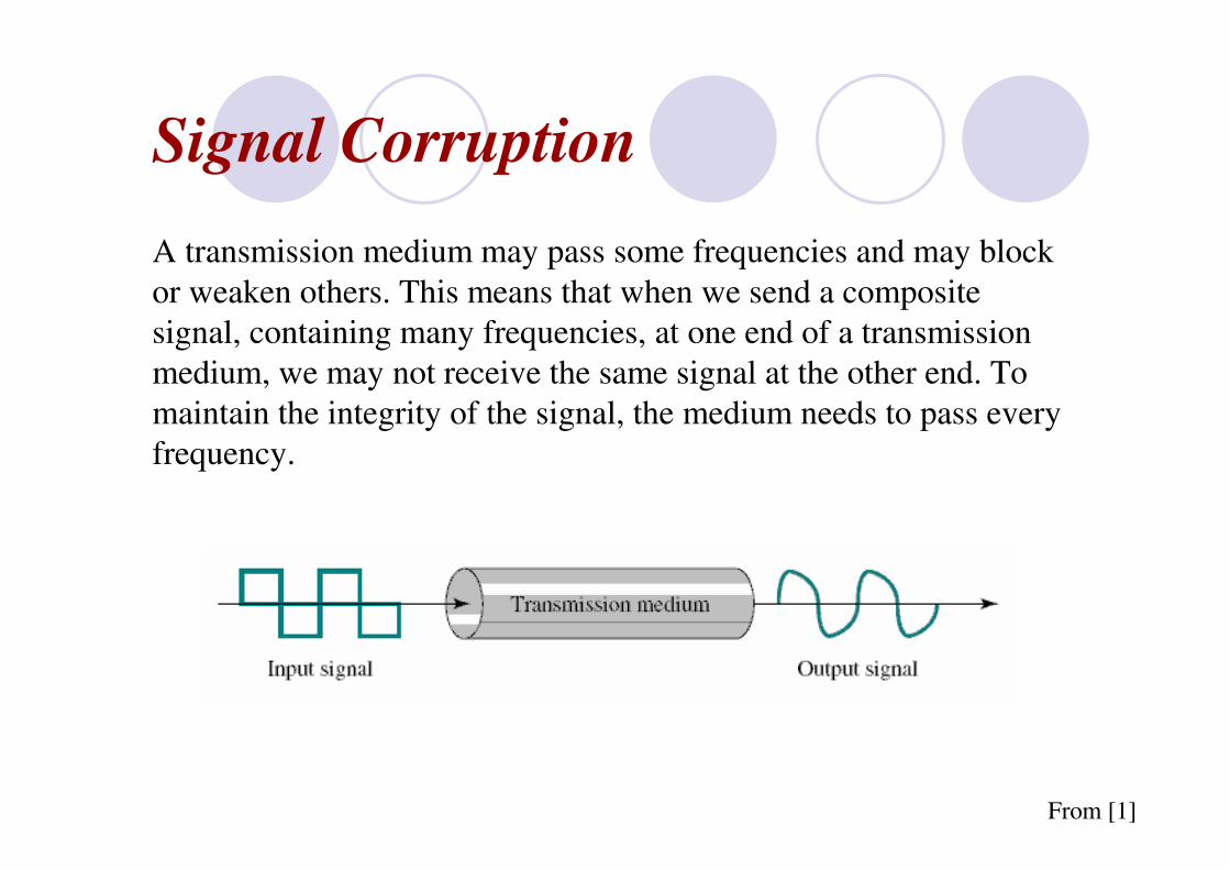
Signal Corruption
A transmission medium may pass some frequencies and may block
or weaken others. This means that when we send a composite
signal, containing many frequencies, at one end of a transmission
medium, we may not receive the same signal at the other end. To
maintain the integrity of the signal, the medium needs to pass every
frequency.
From [1]

Bandwidth
The range of frequencies that a medium can pass is called bandwidth. The bandwidth is a range and is normally referred to as the difference between the highest and the lowest frequenciesthat the medium can satisfactorily pass.
If the bandwidth of a medium does not match the spectrum of a signal, some of the frequencies are lost. Square wave signals have a spectrum that expands to infinity. No transmission medium has such a bandwidth. This means that passing a square wave through any medium will always deform the signal.
From [1]

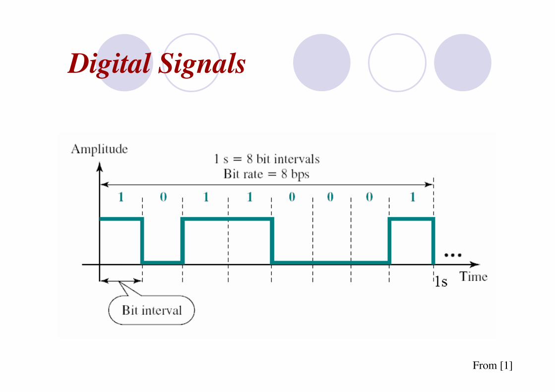
Digital Signals
In addition to being represented by an analog signal, data can be
represented by a digital signal. For example, a 1 can be encoded as a
positive voltage and a 0 as zero voltage. Remember that a digital
signal is a composite signal with an infinite bandwidth.
Most digital signals are aperiodic, and thus period or frequency is
not appropriate. Two new terms—bit interval (instead of period)
and bit rate (instead of frequency)—are used to describe digital
signals.
The bit interval is the time required to send one single bit.
The bit rate is the number of bit intervals per second. This means
that the bit rate is the number of bits sent in 1 s, usually expressed in
bits per second (bps).
Digital Signals
From [1]
Digital Signals through different Bandwidth
Digital Signal Through a Wide-Bandwidth Medium
We can send a digital signal through them (e.g. coaxial cables for a LAN). Some of the frequencies are blocked by the medium, but still enough frequencies are passed to preserve a decent signal shape.
Digital Signal Through a Band-Limited Medium
We can send digital signal through them (e.g. telephone lines for the internet). There is a relationship between minimum required bandwidth B in hertz if we want to send n bps.
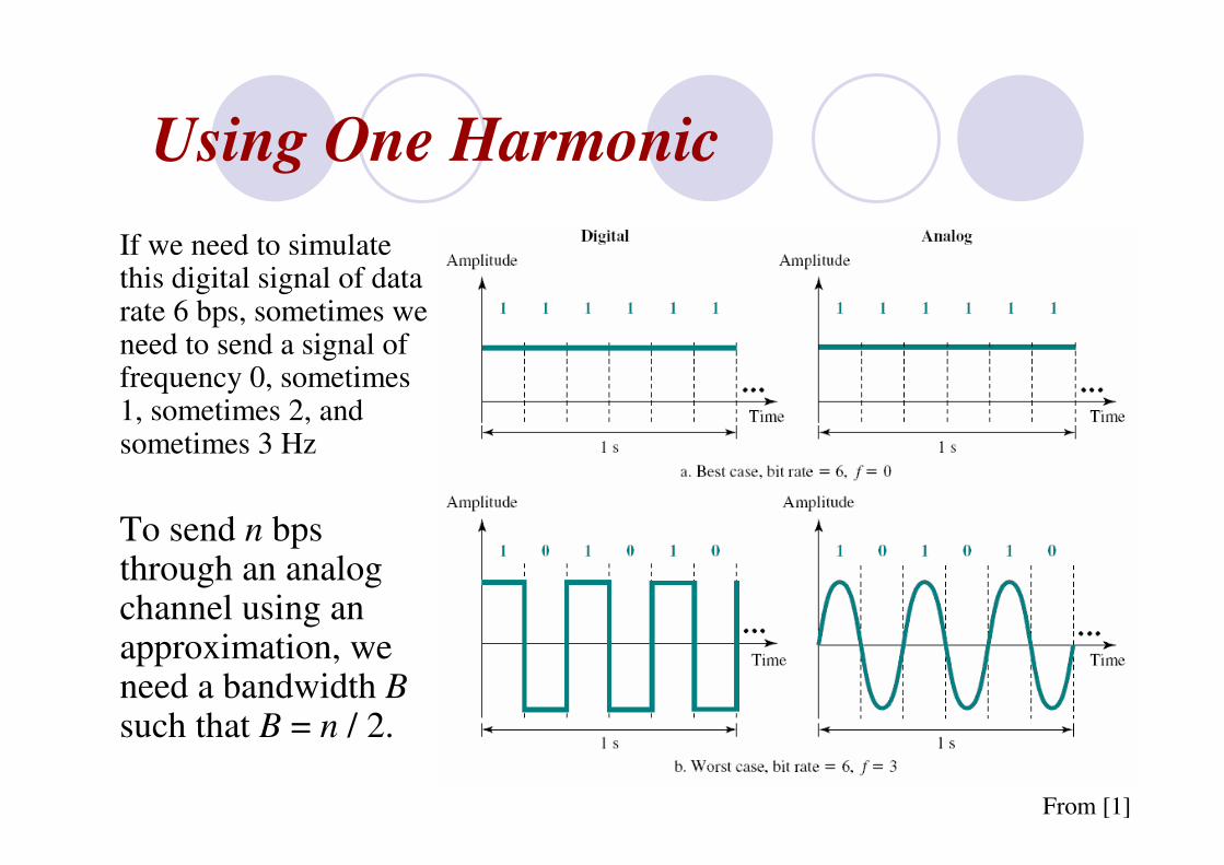
Using One Harmonic
If we need to simulate this digital signal of data rate 6 bps, sometimes we need to send a signal of frequency 0, sometimes 1, sometimes 2, and sometimes 3 Hz
To send n bps through an analog channel using an approximation, we need a bandwidth B such that B = n / 2.
From [1]
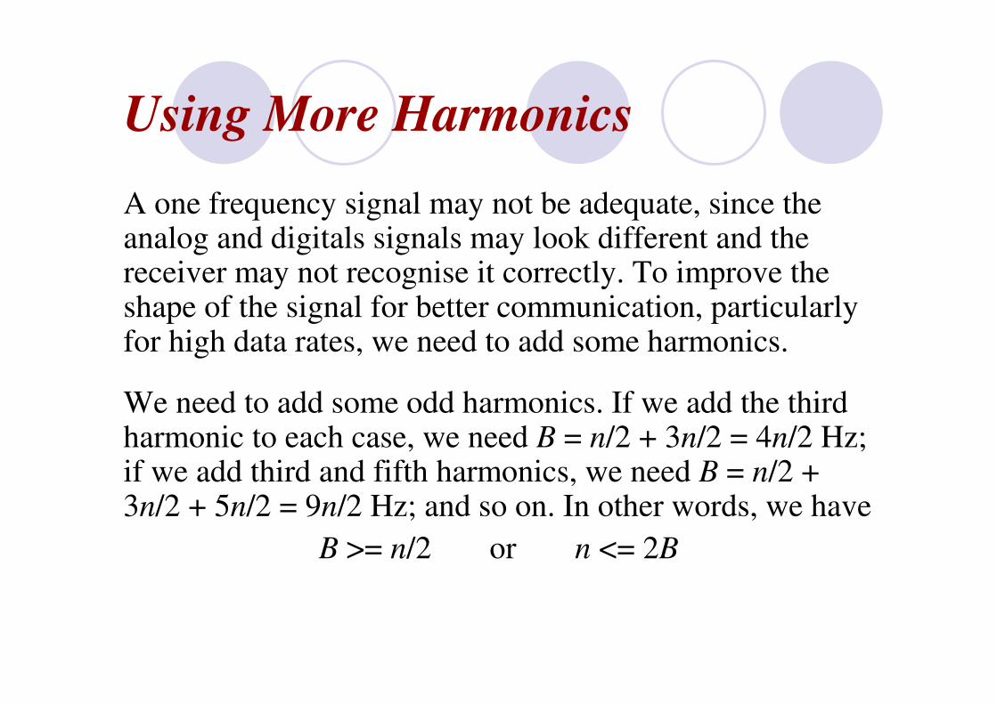
Using More Harmonics
A one frequency signal may not be adequate, since the analog and digitals signals may look different and the receiver may not recognise it correctly. To improve the shape of the signal for better communication, particularly for high data rates, we need to add some harmonics.
We need to add some odd harmonics. If we add the third harmonic to each case, we need B = n/2 + 3n/2 = 4n/2 Hz; if we add third and fifth harmonics, we need B = n/2 + 3n/2 + 5n/2 = 9n/2 Hz; and so on. In other words, we have
B >= n/2 or n <= 2B
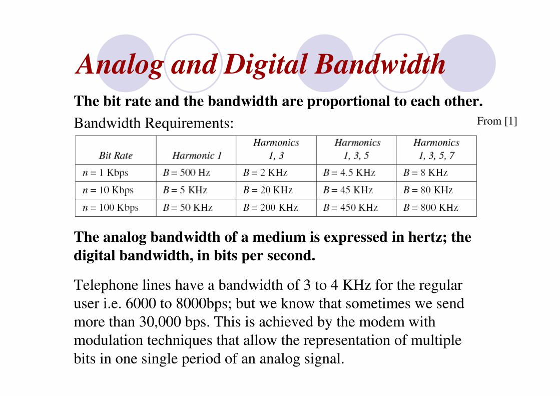
Analog and Digital BandwidthThe bit rate and the bandwidth are proportional to each other.
Bandwidth Requirements:
The analog bandwidth of a medium is expressed in hertz; the
digital bandwidth, in bits per second.
Telephone lines have a bandwidth of 3 to 4 KHz for the regular
user i.e. 6000 to 8000bps; but we know that sometimes we send
more than 30,000 bps. This is achieved by the modem with
modulation techniques that allow the representation of multiple
bits in one single period of an analog signal.
From [1]

Low-pass and Band-pass Channels
A channel or a link is either low-pass or band-pass.
A low-pass channel has a bandwidth with frequencies between 0 and f. The lower limit is 0, the upper limit can be any frequency (including infinity).
A band-pass channel has a bandwidth with frequencies between f1and f2.
A digital signal theoretically needs a bandwidth between 0 and infinity (i.e. a low-pass channel). The lower limit (0) is fixed; the upper limit (infinity) can be relaxed if we lower our standards by accepting a limited number of harmonics.
An analog signal requires a band-pass channel since normally it has a narrower bandwidth than a digital signal. we can always shift a signal with a bandwidth from f1 to f2 to a signal with a bandwidth from f3 to f4 as long as the width of the bandwidth remains the same.

Data Rate Limits and Nyquist Bit Rate
Data rate depends on three factors:
1. The bandwidth available
2. The levels of signals we can use
3. The quality of the channel (the level of the noise).
For a noiseless channel, the Nyquist bit rate formula
defines the theoretical maximum bit rate:
BitRate = 2 x Bandwidth x log2 L
(L is the number of signal levels used to represent data)

Nyquist BitRate = 2 x Bandwidth x log2 L
From [1]
Data Rate Limits and Shannon Capacity
In reality a channel is always noisy. The Shannon
capacity formula is used to determine the theoretical
highest data rate for a noisy channel:
Capacity = Bandwidth × log2 (1 + SNR)
= Bandwidth × 3.32 log10 (1 + SNR)
SNR is the signal-to-noise ratio, and Capacity is the
capacity of the channel in bits per second. The signal-to-
noise ratio is the statistical ratio of the power of the signal
to the power of the noise. In practice, the SNR is expressed in
dB. (SNR)dB = 10 log10(Psignal/Pnoise), but it must be made unitless
before applying Shannon’s formula
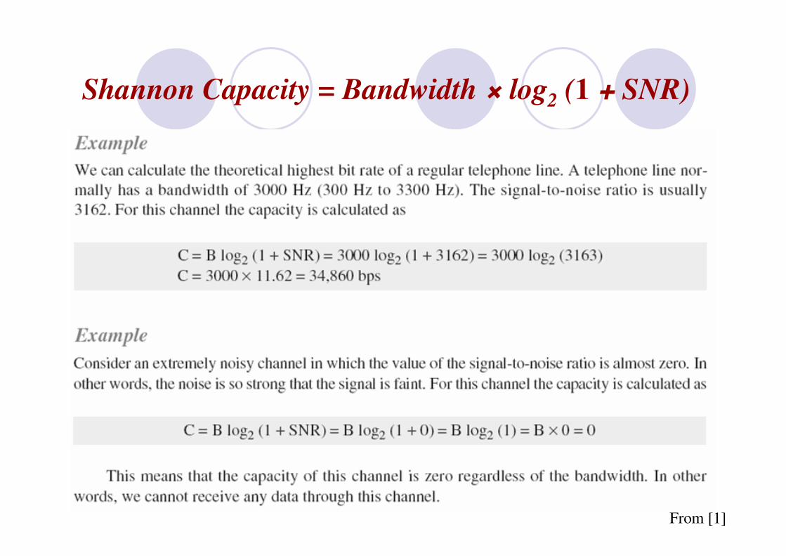
Shannon Capacity = Bandwidth × log2 (1 + SNR)
From [1]

Transmission Impairment - Attenuation
Signals travel through transmission media, which are not perfect.
The imperfections cause impairment in the signal i.e. the signal at
the beginning and end of the medium are not the same.
3 types of impairment usually occur: attenuation, distortion & noise
Attenuation means loss of energy. When a signal, simple or
composite, travels through a medium, it loses some of its energy so
that it can overcome the resistance of the medium. To compensate
for this loss amplifiers are used to amplify (strengthen) the signal:
From [1]

Attenuation, Amplification and the Decibel
Amplification simply refers to the strengthening of a signal whereas attenuation refers to its weakening.
The decibel (dB) measures the relative strengths of two signals or a signal at two different points. Note that the decibel is negative if a signal is attenuated and positive if a signal is amplified.
AdB = 10 log10 (P2 / P1)
where P1 and P2 are the powers of a signal at points 1 and 2, respectively
In the diagram above x = – 3 + 7 – 3 = 1
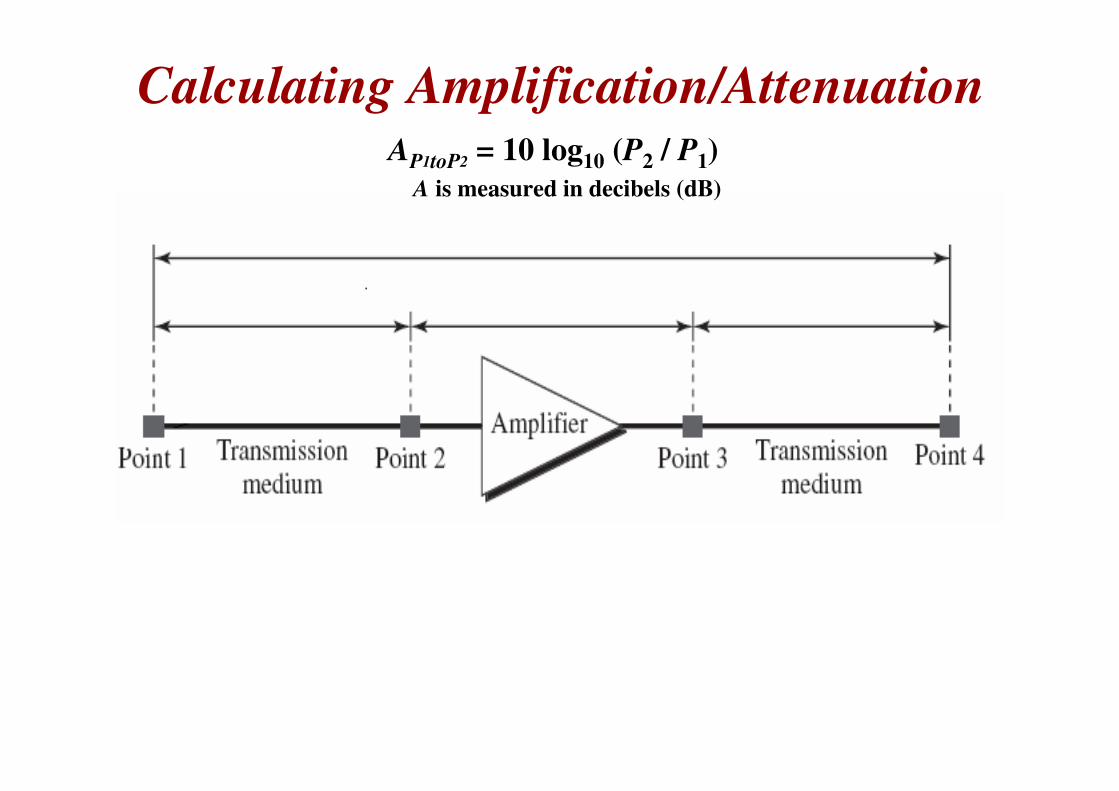
Calculating Amplification/AttenuationAP1toP2 = 10 log10 (P2 / P1)
A is measured in decibels (dB)
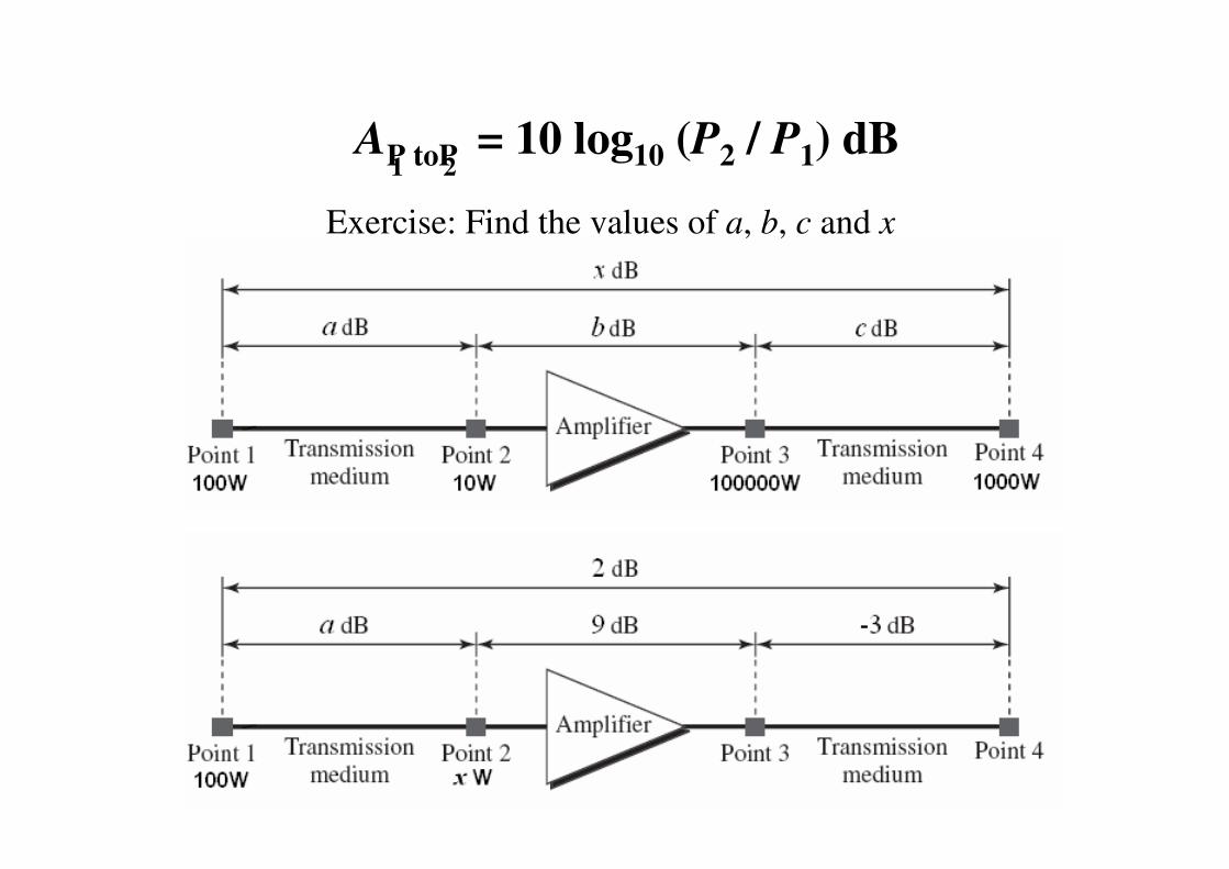
AP toP = 10 log10 (P2 / P1) dB
Exercise: Find the values of a, b, c and x
1 2
Transmission Impairment - Distortion
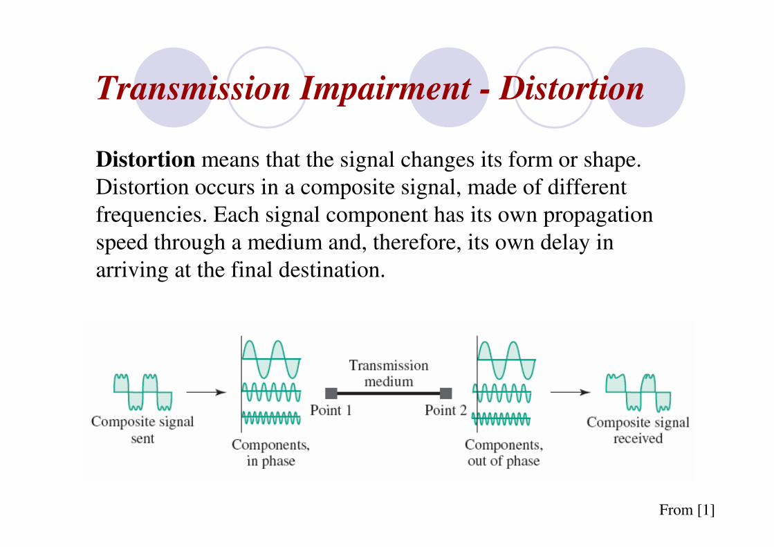
Distortion means that the signal changes its form or shape.
Distortion occurs in a composite signal, made of different
frequencies. Each signal component has its own propagation
speed through a medium and, therefore, its own delay in
arriving at the final destination.
From [1]

Transmission Impairment - Noise
Noise is another problem. Several types of noise such as thermal
noise, induced noise, crosstalk, and impulse noise may corrupt the
signal.
Thermal noise is the random motion of electrons in a wire which
creates an extra signal not originally sent by the transmitter.
Induced noise comes from sources such as motors and appliances.
These devices act as a sending antenna and the transmission
medium acts as the receiving antenna.
From [1]
Throughput
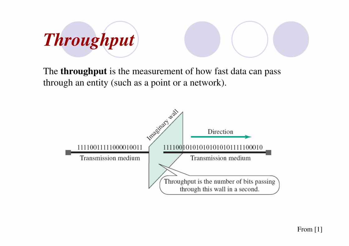
The throughput is the measurement of how fast data can pass
through an entity (such as a point or a network).
From [1]
Propagation Speed and Time
Propagation speed measures the distance a signal or a bit
can travel through a medium in one second. The
propagation speed of electromagnetic signals depends on
the medium and on the frequency of the signal. For
example, in a vacuum, light is propagated with a speed of
3 × 10⁸ m/s. It is lower in air. It is much lower in a cable.
Propagation time measures the time required for a signal
(or a bit) to travel from one point of the transmission
medium to another. The propagation time is calculated by
dividing the distance by the propagation speed.
Propagation time = Distance/Propagation speed
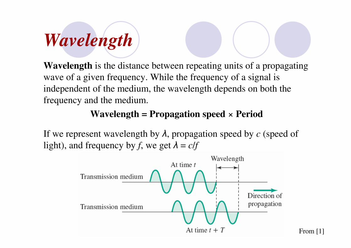
Wavelength
Wavelength is the distance between repeating units of a propagating
wave of a given frequency. While the frequency of a signal is
independent of the medium, the wavelength depends on both the
frequency and the medium.
Wavelength = Propagation speed × Period
If we represent wavelength by λ, propagation speed by c (speed of
light), and frequency by f, we get λ = c/f
From [1]

The Electromagnetic SpectrumElectromagnetic Radiation is a self-propagating wave in space with electric and magnetic components. EM radiation carries energy and momentum, which may be imparted when it interacts with matter.
EM-waves are classified according to their varying frequencies (and consequent wavelengths). They include in order of increasing frequency, radio waves, microwaves, infrared radiation, visible light, ultraviolet radiation, X-rays and gamma rays.
All EM-radiation travel through vacuum at a propagation speed of 299,792,458 m/s(approx. 3 x 10⁸ m/s), i.e. the speed of light.
The electromagnetic spectrum is the range of all possible electromagnetic radiation.
Terahertz
From [3]

From [3]