introduction to plasma arc cutting m3 u7 - ecollege
TRANSCRIPT

Trade of Sheet Metalwork Module 3: Thermal Processes
Unit 7: Introduction to Plasma Arc Cutting
Phase 2

Trade of Sheet Metalwork – Phase 2 Module 3 Unit 7
Unit 7 3
Table of Contents
List of Figures .................................................................................................................... 5
List of Tables ..................................................................................................................... 5
Document Release History ............................................................................................... 6
Module 3 – Thermal Processes ........................................................................................ 7
Unit 7 – Introduction to Plasma Arc Cutting .................................................................. 7 Learning Outcome: ..................................................................................................... 7 Key Learning Points: .................................................................................................. 7 Training Resources: .................................................................................................... 7 Key Learning Points Code: ......................................................................................... 7
Plasma ................................................................................................................................ 9
Plasma Definition ........................................................................................................... 9 Plasma in Nature ............................................................................................................. 9 Cutting with Plasma ...................................................................................................... 10
Gas Selection.................................................................................................................... 11
Plasma Gas .................................................................................................................... 11 Shield Gas ..................................................................................................................... 11 Selecting the Right Gas ................................................................................................. 12
Consumables .................................................................................................................... 13
Installing Consumables ................................................................................................. 13 Recording Consumable Life ......................................................................................... 14
Safety ................................................................................................................................ 15
Additional Safety Information ...................................................................................... 22 Warning Label .............................................................................................................. 23
Symbols and Markings ................................................................................................... 25
S Mark .......................................................................................................................... 25 IEC Symbols Used ........................................................................................................ 25
Installing Torch Consumables ....................................................................................... 26
Mode Switch .................................................................................................................... 27
Turn ON Power ............................................................................................................... 27
Check Indicator Lights ................................................................................................... 27
Adjust Gas Pressure and Current Setting .................................................................... 28

Trade of Sheet Metalwork – Phase 2 Module 3 Unit 7
Unit 7 4
Hand Torch Operation ................................................................................................... 29
Safety Trigger Operation .............................................................................................. 29 Attach the Work Clamp ................................................................................................ 30 Starting a Cut from the Edge of the Workpiece ............................................................ 30 Hand Torch Cutting Technique .................................................................................... 31 Piercing ......................................................................................................................... 32 Gouging ........................................................................................................................ 33 40 Amp Mechanised Shielded Consumables ................................................................ 34
Parts ................................................................................................................................. 35
Torch Consumable Configurations ............................................................................... 35 Routine Maintenance .................................................................................................... 36 Inspect Consumables .................................................................................................... 37 Controls and Indicators ................................................................................................. 38
Indicator LEDs .......................................................................................................... 39 Basic Troubleshooting .................................................................................................. 40
Main Function Selection Menu ...................................................................................... 43
Shape.1 Shape Selection ............................................................................................ 48
2.5RS Operation and Maintenance Manual .................................................................. 49
Shapes.2 Dimensions Common to Most Shapes ....................................................... 50
2.5RS Operation and Maintenance Manual .................................................................. 51
Self Assessment................................................................................................................ 53
Answers to Questions 1-5. Module 3.Unit 7 .................................................................. 55
Index ................................................................................................................................. 57

Trade of Sheet Metalwork – Phase 2 Module 3 Unit 7
Unit 7 5
List of Figures
Figure 1 - Plasma Arc Cutting ............................................................................................ 8
Figure 2 - Plasma - The Fourth State of Matter .................................................................. 9
Figure 3 - Gas Selection .................................................................................................... 11
Figure 4 - Installing Consumables .................................................................................... 13
Figure 5 - Warning Label .................................................................................................. 23
Figure 6 - IEC Symbols .................................................................................................... 25
Figure 7 - Routine Maintenance ....................................................................................... 36
Figure 8 - Inspect Consumables ........................................................................................ 37
Figure 9 - Controls and Indicators .................................................................................... 38
Figure 10 - Outside Row on Keypad ................................................................................ 49
Figure 11 - Shapes ............................................................................................................ 52
List of Tables
Table 1 - Cutting with Plasma .......................................................................................... 10
Table 2 - Gas Selection Chart ........................................................................................... 12
Table 3 - Consumable Usage Log ..................................................................................... 14
Table 4 - Cut Charts .......................................................................................................... 34
Table 5 - Function Selection Menu ................................................................................... 43

Trade of Sheet Metalwork – Phase 2 Module 3 Unit 7
Unit 7 6
Document Release History
Date Version Comments
18/09/06 First draft
07/04/14 2.0 SOLAS transfer

Trade of Sheet Metalwork – Phase 2 Module 3 Unit 7
Unit 7 7
Module 3 – Thermal Processes
Unit 7 – Introduction to Plasma Arc Cutting
Duration – 4 Hours
Learning Outcome:
By the end of this unit each apprentice will be able to:
List the applications, characteristics and hazards associated with plasma cutting
Safely set up the equipment, adjust air pressure and current to correct settings for exercise
State the safety precautions to be observed
Cut mild steel/stainless/galvanised mild steel and aluminium sheet freehand and with attachments
Key Learning Points:
Sk Rk Assembly of equipment.
Rk M Regulation of air pressure.
Sk Rk Regulation of current.
Sk Rk Maintenance and care of plant.
H Rk Safety standards and procedures.
Rk Identification of various attachments.
Sk Cutting techniques.
Training Resources:
Plasma arc cutting plant and range of attachments – safety clothing and personal protection equipment. Fabrication workshop.
Key Learning Points Code:
M = Maths D= Drawing RK = Related Knowledge Sc = Science
P = Personal Skills Sk = Skill H = Hazards
* The following notes are based on the plasma equipment in the Waterford training centre and may need some adjustment to meet the needs of the equipment in the Finglas training centre.

Trade of Sheet Metalwork – Phase 2 Module 3 Unit 7
Unit 7 8
Figure 1 - Plasma Arc Cutting

Trade of Sheet Metalwork – Phase 2 Module 3 Unit 7
Unit 7 9
Plasma
"The fourth state of matter"
The first three states of matter are solid, liquid and gas. For the most commonly known substance, water, these states are ice, water and steam. If you add heat energy, the ice will change from a solid to a liquid, and if more heat is added, it will change to a gas (steam). When substantial heat is added to a gas, it will change from gas to plasma, the fourth state of matter.
Figure 2 - Plasma - The Fourth State of Matter
Plasma Definition
Plasma is an electrically conductive gas. The ionisation of gases causes the creation of free electrons and positive ions among the gas atoms. When this occurs, the gas becomes electrically conductive with current carrying capabilities. Thus, it becomes a plasma.
Plasma in Nature
One example of plasma, as seen in nature, is lightning. Just like a plasma torch, the lightning moves electricity from one place to another.
In lightning, gases in the air are the ionisation gases.

Trade of Sheet Metalwork – Phase 2 Module 3 Unit 7
Unit 7 10
Cutting with Plasma
Plasma cutting is a process that utilises an optimised nozzle orifice to constrict a very high- temperature, ionised gas so that it can be used to melt and sever sections of electrically conductive metals.
The plasma arc melts the metal, and the high velocity gas removes the molten material.
System Material Type Max Cut Capacity Max Pierce Capacity
HD3070 Mild Steel ½˝ ½˝
Stainless Steel ½˝ ½˝
Aluminium ½˝ ½˝
MAX200 Mild Steel 2˝ 1˝
Stainless Steel 2˝ ⅞˝
Aluminium 2˝ ⅞˝
HT2000 Mild Steel 2˝ 1˝
Stainless Steel 2˝ ⅞˝
Aluminium 2˝ ⅞˝
HT4001 Mild Steel w/O2 1¼˝ 1˝
Mild Steel w/N2 3˝ 1˝
Stainless Steel 3˝ 1˝
Table 1 - Cutting with Plasma
Trade of Sheet Metalwork – Phase 2 Module 3 Unit 7
Unit 7 11
Gas Selection
Selecting the proper gas for the material you are cutting is critical to get a quality cut.
Plasma Gas
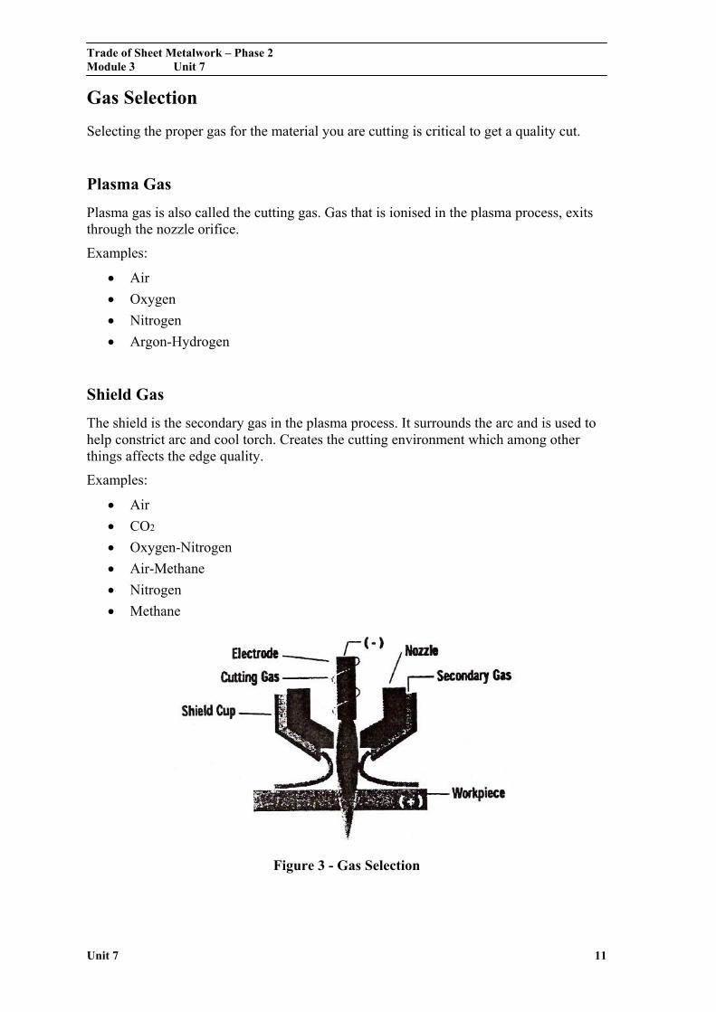
Plasma gas is also called the cutting gas. Gas that is ionised in the plasma process, exits through the nozzle orifice.
Examples:
Air
Oxygen
Nitrogen
Argon-Hydrogen
Shield Gas
The shield is the secondary gas in the plasma process. It surrounds the arc and is used to help constrict arc and cool torch. Creates the cutting environment which among other things affects the edge quality.
Examples:
Air
CO2
Oxygen-Nitrogen
Air-Methane
Nitrogen
Methane
Figure 3 - Gas Selection

Trade of Sheet Metalwork – Phase 2 Module 3 Unit 7
Unit 7 12
Selecting the Right Gas
Gas quality is critical for the proper operation of plasma arc cutting systems and optimal cut quality. Any contaminates can cause misfiring, poor cut quality or poor consumable life.
Contaminates can be: gas impurities, moisture, dirt, piping system contaminates or improper gases (i.e. Air in O2 systems-leaks, not following proper purge procedures when changing gas).
Gas Selection Chart
System Material Plasma Gas Shield Gas
HyDefinition Mild Steel O2 O2 & N2
Stainless Steel up to ¼˝
above ¼˝
above ¼˝ *
Air Air
Air Air & Methane
H35 & N2 N2
Aluminium up to ⅜˝
up to ½˝
Air CH4
H35 & N2 N2
Copper O2 O2 & N2
MAX200 & HT2000
Mild Steel O2 Air
Stainless Steel up to ¼˝
above ½˝
Air Air
H35 N2
Aluminium Air Air
Copper O2 Air
HT4001 Mild Steel ** O2 H2O
Stainless Steel N2 H2O
Aluminium N2 H2O
* Only valid if equipped with six channel gas console (p/n: 078059 & 078061).
** O2 cutting is only for 340 amps maximum. Must use N2 for higher current.
Table 2 - Gas Selection Chart
Trade of Sheet Metalwork – Phase 2 Module 3 Unit 7
Unit 7 13
Consumables
Installing Consumables
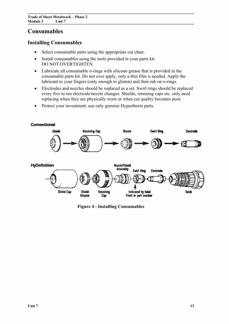
Select consumable parts using the appropriate cut chart.
Install consumables using the tools provided in your parts kit. DO NOT OVERTIGHTEN.
Lubricate all consumable o-rings with silicone grease that is provided in the consumable parts kit. Do not over apply, only a thin film is needed. Apply the lubricant to your fingers (only enough to glisten) and then rub on o-rings.
Electrodes and nozzles should be replaced as a set. Swirl rings should be replaced every five to ten electrode/nozzle changes. Shields, retaining caps etc. only need replacing when they are physically worn or when cut quality becomes poor.
Protect your investment: use only genuine Hypertherm parts.
Figure 4 - Installing Consumables

Trade of Sheet Metalwork – Phase 2 Module 3 Unit 7
Unit 7 14
Recording Consumable Life
Recording consumable life is an important task that should be done each time consumables are changed.
With records like this you will easily see when you are having a consumable life problem and will aid in effective troubleshooting.
The chart below is a good example for your log.
Consumable Usage Log
Starts Arc Time Errors Material Cut
Current/Process
Consumable Part #
Notes
Start End
Table 3 - Consumable Usage Log

Trade of Sheet Metalwork – Phase 2 Module 3 Unit 7
Unit 7 15
Safety
RECOGNISE SAFETY INFORMATION
The symbols shown in this section are used to identify potential hazards. When you see a safety symbol in this manual or on your machine, understand the potential for personal injury, and follow the related instructions to avoid the hazard.
FOLLOW SAFETY INSTRUCTIONS
Read carefully all safety messages in this manual and safety labels on your machine.
Keep the safety labels on your machine in good condition. Replace missing or damaged labels immediately.
Learn how to operate the machine and how to use the controls properly. Do not let anyone operate it without instruction.
Keep your machine in proper working condition. Unauthorised modifications to the machine may affect safety and machine service life.
DANGER WARNING CAUTION
A signal word DANGER or WARNING is used with a safety symbol. DANGER identifies the most serious hazards.
DANGER and WARNING safety labels are located on your machine near specific hazards.
WARNING safety messages precede related instructions in this manual that may result in injury or death if not followed correctly.
CAUTION safety messages precede related instructions in this manual that may result in damage to equipment if not followed correctly.

Trade of Sheet Metalwork – Phase 2 Module 3 Unit 7
Unit 7 16
CUTTING CAN CAUSE FIRE OR EXPLOSION
Fire Prevention
Be sure the area is safe before doing any cutting.
Keep a fire extinguisher nearby.
Remove all flammables within 35 feet (10 m) of the cutting area.
Quench hot metal or allow it to cool before handling or before letting it touch combustible materials.
Never cut containers with potentially flammable materials inside - they must be emptied and properly cleaned first.
Ventilate potentially flammable atmospheres before cutting.
When cutting with oxygen as the plasma gas, an exhaust ventilation system is required.
Explosion Prevention
Do not use the plasma system if explosive dust or vapours may be present.
Do not cut pressurised cylinders, pipes, or any closed container.
Do not cut containers that have held combustible materials.
WARNING
Explosion Hazard
Argon-Hydrogen and Methane
Hydrogen and methane are flammable gases that present an explosion hazard. Keep flames away from cylinders and hoses that contain methane or hydrogen mixtures. Keep flames and sparks away from the torch when using methane or argon-hydrogen plasma.
WARNING
Hydrogen Detonation with Aluminium Cutting
When cutting aluminium underwater, or with the water touching the underside of the aluminium, free hydrogen gas may collect under the workpiece and detonate during plasma cutting operations.
Install an aeration manifold on the floor of the water table to eliminate the possibility of hydrogen detonation. Refer to the Appendix section of this manual for aeration manifold details.

Trade of Sheet Metalwork – Phase 2 Module 3 Unit 7
Unit 7 17
ELECTRIC SHOCK CAN KILL
Touching live electrical parts can cause a fatal shock or severe burn.
Operating the plasma system completes an electrical circuit between the torch and the workpiece. The workpiece and anything touching the workpiece are part of the electrical circuit.
Never touch the torch body, workpiece or the water in a water table when the plasma system is operating.
Electric Shock Prevention
All Hypertherm plasma systems use high voltage in the cutting process (200 to 400 VDC are common). Take the following precautions when operating this system:
Wear insulated gloves and boots, and keep your body and clothing dry.
Do not stand sit or lie on - or touch - any wet surface when using the plasma system.
Insulate yourself from work and ground using dry insulating mats or covers big enough to prevent any physical contact with the work or ground. If you must work in or near a damp area, use extreme caution.
Provide a disconnect switch close to the power supply with property sized fuses. This switch allows the operator to turn off the power supply quickly in an emergency situation.
When using a water table, be sure that it is correctly connected to earth ground.
Install and ground this equipment according to the instruction manual and in accordance with national and local codes.
Inspect the input power cord frequently for damage or cracking of the cover. Replace a damaged power cord immediately. Bare wiring can kill.
Inspect and replace any worn or damaged torch leads.
Do not pick up the workpiece, including the waste cut off, while you cut. Leave the workpiece in place or on the workbench with the work cable attached during the cutting process.
Before checking, cleaning or changing torch parts, disconnect the main power or unplug the power supply.
Never bypass or shortcut the safety interlocks.
Before removing any power supply or system enclosure cover, disconnect electrical input power. Wait 5 minutes after disconnecting the main power to allow capacitors to discharge.
Never operate the plasma system unless the power supply covers are in place. Exposed power supply connections present a severe electrical hazard.
When making input connections, attach proper grounding conductor first.
Each Hypertherm plasma system is designed to be used only with specific Hypertherm torches. Do not substitute other torches which could overheat and present a safety hazard.

Trade of Sheet Metalwork – Phase 2 Module 3 Unit 7
Unit 7 18
CUTTING CAN PRODUCE TOXIC FUMES
Cutting can produce toxic fumes and gases that deplete oxygen and cause injury or death.
Keep the cutting area well ventilated or use an approved air-supplied respirator.
Do not cut in locations near degreasing, cleaning or spraying operations. The vapours from certain chlorinated solvents decompose to form phosgene gas when exposed to ultraviolet radiation.
Do not cut metal coated or containing toxic materials, such as zinc (galvanised), lead, cadmium or beryllium, unless the area is well ventilated and the operator wears an air-supplied respirator. The coatings and any metals containing these elements can produce toxic fumes when cut
Never cut containers with potentially toxic materials inside - they must be emptied and property cleaned first.
This product, when used for welding or cutting, produces fumes or gases which contain chemicals known to the State of California to cause birth defects and, in some cases, cancer.

Trade of Sheet Metalwork – Phase 2 Module 3 Unit 7
Unit 7 19
A PLASMA ARC CAN CAUSE INJURY AND BURNS
Instant-On Torches
Plasma arc comes on immediately when the torch switch is activated.
The plasma arc will cut quickly through gloves and skin.
Keep away from the torch tip.
Do not hold metal near the cutting path.
Never point the torch toward yourself or others.
ARC RAYS CAN BURN EYES AND SKIN
Eye Protection Plasma arc rays produce intense visible and invisible (ultraviolet and infrared) rays that can bum eyes and skin.
Use eye protection in accordance with applicable national or local codes.
Wear eye protection (safety glasses or goggles with side shields, or a welding helmet) with appropriate lens shading to protect your eyes from the arc's ultraviolet and infrared rays.
Arc Current
Lens Shade
AWS (USA) ISO 4850
Up to 100 A No. 8 No. 11
100-200 A No. 10 No. 11-12
200-400 A No. 12 No. 13
Over 400 A No. 14 No. 14
Skin Protection Wear protective clothing to protect against bums caused by ultraviolet light, sparks and hot metal.
Gauntlet gloves, safety shoes and hat.
Flame-retardant clothing to cover all exposed areas.
Cuffless trousers to prevent entry of sparks arid slag.
Remove any combustibles, such as a butane lighter or matches, from your pockets before cutting.
Cutting Area Prepare the cutting area to reduce reflection and transmission of ultraviolet light:
Paint walls and other surfaces with dark colours to reduce reflection.
Use protective screens or barriers to protect others from flash and glare.
Warn others not to watch the arc. Use placards or signs.

Trade of Sheet Metalwork – Phase 2 Module 3 Unit 7
Unit 7 20
GROUNDING SAFETY
Work Cable Attach the work cable securely to the workpiece or the work table with good metal-to-metal contact. Do not connect it to the piece that will fall away when the cut is complete.
Work Table Connect the work table to an earth ground, in accordance with appropriate national or local electrical codes.
Input Power
Be sure to connect the power cord ground wire to the ground in the disconnect box.
If installation of the plasma system involves connecting the power cord to the power supply, be sure to connect the power cord ground wire properly.
Place the power cord's ground wire on the stud first, then place any other ground wires on top of the power cord ground. Fasten the retaining nut tightly.
Tighten all electrical connections to avoid excessive heating.
COMPRESSED GAS EQUIPMENT SAFETY
Never lubricate cylinder valves or regulators with oil or grease.
Use only correct gas cylinders, regulators, hoses and fittings designed for the specific application.
Maintain all compressed gas equipment and associated parts in good condition.
Label and colour-code all gas hoses to identify the type of gas in each hose. Consult applicable national or local codes.
GAS CYLINDERS CAN EXPLODE IF DAMAGED
Gas cylinders contain gas under high pressure. If damaged, a cylinder can explode.
Handle and use compressed gas cylinders in accordance with applicable national or local codes.
Never use a cylinder that is not upright and secured in place.
Keep the protective cap in place over valve except when the cylinder is in use or connected for use.
Never allow electrical contact between the plasma arc and a cylinder.
Never expose cylinders to excessive heat, sparks, slag or open flame.
Never use a hammer, wrench or other tool to open a stuck cylinder valve.
Trade of Sheet Metalwork – Phase 2 Module 3 Unit 7
Unit 7 21
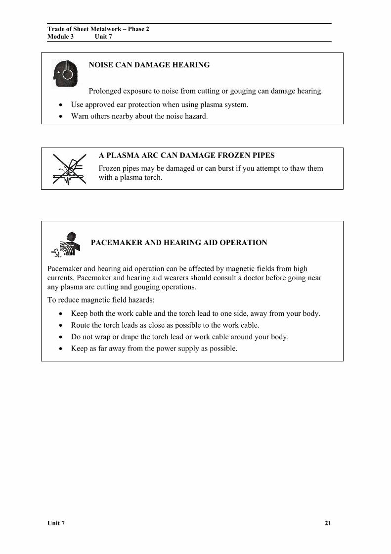
NOISE CAN DAMAGE HEARING
Prolonged exposure to noise from cutting or gouging can damage hearing.
Use approved ear protection when using plasma system.
Warn others nearby about the noise hazard.
A PLASMA ARC CAN DAMAGE FROZEN PIPES
Frozen pipes may be damaged or can burst if you attempt to thaw them with a plasma torch.
PACEMAKER AND HEARING AID OPERATION
Pacemaker and hearing aid operation can be affected by magnetic fields from high currents. Pacemaker and hearing aid wearers should consult a doctor before going near any plasma arc cutting and gouging operations.
To reduce magnetic field hazards:
Keep both the work cable and the torch lead to one side, away from your body.
Route the torch leads as close as possible to the work cable.
Do not wrap or drape the torch lead or work cable around your body.
Keep as far away from the power supply as possible.

Trade of Sheet Metalwork – Phase 2 Module 3 Unit 7
Unit 7 22
Additional Safety Information
1. ANSI Standard Z49.1, Safety in Welding and Cutting, American Welding Society, 550 LeJeune Road P.O. Box 351020. Miami, FL 33135
2. ANSI Standard Z49.2, Fire Prevention in the Use of Cutting and Welding Processes, American National Standards Institute 1430 Broadway, New York, NY 10018
3. ANSI Standard Z87.1, Safe Practices for Occupation and Educational Eye and Face Protection, American National Standards Institute, 1430 Broadway, New York, NY 10018
4. AWS F4.1, Recommended Safe Practices for the Preparation for Welding and Cutting of Containers and Piping That Have Held Hazardous Substances, American Welding Society 550 LeJeune Road, P.O. Box 351040, Miami, FL 33135
5. AWS F5.2, Recommended Safe Practices for Plasma Arc Cutting, American Welding Society 550 LeJeune Road, P.O. Box 351040, Miami, FL 33135
6. CGA Pamphlet P-1, Safe Handling of Compressed Gases in Cylinders, Compressed Gas Association 1235 Jefferson Davis Highway, Arlington, VA 22202
7. CSA Standard W117.2, Code for Safety in Welding and Cutting, Canadian Standards Association Standard Sales 178 Rexdale Boulevard, Rexdale, Ontario M9W 1 R3, Canada
8. NFPA Standard 51B, Cutting and Welding Processes, National Fire Protection Association 470 Atlantic Avenue, Boston, MA 02210
9. NFPA Standard 70-1978, National Electrical Code, National Fire Protection Association, 470 Atlantic Avenue, Boston, MA 02210
10. OSHA Safety and Health Standards, 29FR 1910 U.S. Government Printing Office, Washington, D.C. 20402

Trade of Sheet Metalwork – Phase 2 Module 3 Unit 7
Unit 7 23
Warning Label
This warning label is affixed to some power supplies. It is important that the operator and maintenance technician understand the intent of these warning symbols as described. The numbered text corresponds to the numbered boxes on the label.
Figure 5 - Warning Label

Trade of Sheet Metalwork – Phase 2 Module 3 Unit 7
Unit 7 24
1. Cutting sparks can cause explosion or fire.
1.1 Keep flammables away from cutting.
1.2 Keep a fire extinguisher nearby, and have a watchperson ready to use it.
1.3 Do not cut on any closed containers.
2. The plasma arc can cause injury and burns.
2.1 Turn off power before disassembling torch.
2.2 Do not hold the material near cutting path.
2.3 Wear complete body protection.
3. Electric shock from torch or wiring can kill. Protect yourself from electric shock.
3.1 Wear insulating gloves. Do not wear wet or damaged gloves.
3.2 Insulate yourself from work and ground.
3.3 Disconnect input plug or power before working on machine.
4. Breathing cutting fumes can be hazardous to your health.
4.1 Keep your head out of the fumes.
4.2 Use forced ventilation or local exhaust to remove the fumes.
4.3 Use ventilating fan to remove the fumes.
5. Arc rays can bum eyes and injure skin.
5.1 Wear hat and safety glasses. Use ear protection and button shirt collar. Use welding helmet with correct shade of fitter. Wear complete body protection.
6. Become trained and read the instructions before working on the machine or cutting.
7. Do not remove or paint over (cover) warning labels.

Trade of Sheet Metalwork – Phase 2 Module 3 Unit 7
Unit 7 25
Symbols and Markings
S Mark
The S mark indicates that the power supply and torch are suitable for use in environments with increased hazard of electrical shock. The hand torches must have shielded consumable parts to maintain S mark compliance.
IEC Symbols Used
The following symbols may appear on the power supply data plate, control labels and switches.
Figure 6 - IEC Symbols

Trade of Sheet Metalwork – Phase 2 Module 3 Unit 7
Unit 7 26
Installing Torch Consumables
1.
2.

Trade of Sheet Metalwork – Phase 2 Module 3 Unit 7
Unit 7 27
Mode Switch
1.
Use to cut expanded metal. Automatically reinitiates pilot.
Use to cut plate/sheet metal. Optimum consumable life.
Use to gouge, or for non-transferred-arc operation.
Turn ON Power
Position the power switch to ON (1) as shown.
Check Indicator Lights
Check that the POWER ON lamp is illuminated.
Check that the Gas Pressure LED is illuminated in Green.
2.
Check that the remaining indicator lamps are NOT illuminated.

Trade of Sheet Metalwork – Phase 2 Module 3 Unit 7
Unit 7 28
Adjust Gas Pressure and Current Setting
1.
See current knob to gas test.
2.
Pull regular knob to unlock.
3.
Set pressure:
Cutting 70-75 psig (4.8-5.2 bar)
Gouging 50-60 psig (3.4-4.1 bar)
4.
Push regular knob to lock.
5.
Turn current knob away from gas test to stop gas flow (25 amps minimum).

Trade of Sheet Metalwork – Phase 2 Module 3 Unit 7
Unit 7 29
Hand Torch Operation
WARNING
INSTANT-ON TORCHES
PLASMA ARC CAN CAUSE INJURY AND BURNS
Plasma arc comes on immediately when the torch switch is activated.
The plasma arc will quickly burn through gloves and skin.
Keep away from the torch tip.
Do not hold the workpiece, and keep your hands clear of the cutting path.
Never point the torch toward yourself or others.
Never use with Pendant Switch.
Safety Trigger Operation
1.
2.
3.

Trade of Sheet Metalwork – Phase 2 Module 3 Unit 7
Unit 7 30
Attach the Work Clamp
WARNING
SPARKS ANDHOT METAL CAN INJURE
EYES AND BURN SKIN
When firing the torch at an angle, sparks and hot metal will spray out from the nozzle. Point the torch away from yourself and others.
Attach the work clamp securely to the workpiece. Remove rust, paint or other coatings to ensure good electrical contact.
Attach the work clamp as close as possible to the area being cut, to reduce exposure to electromagnetic fields (EMF).
Do not attach the work clamp to the portion that will fall away.
Starting a Cut from the Edge of the Workpiece
Hold the torch nozzle vertical at the edge of the workpiece.
Start cutting from the edge of the workpiece.
Pause at the edge until the arc has completely cut through the workpiece.
Then, proceed with the cut.

Trade of Sheet Metalwork – Phase 2 Module 3 Unit 7
Unit 7 31
Hand Torch Cutting Technique
Firing the torch unnecessarily reduces nozzle and electrode life.
When cutting, make sure that sparks are exiting from the bottom of the workpiece.
If the sparks are spraying up from the workpiece, you are moving the torch too fast, or without sufficient power.
Position the torch nozzle at a vertical position and watch the arc as it cuts along the line.
Unshielded Consumables. Maintain an approximate ⅛ inch (3 mm) torch-to-work distance.
Shielded Consumables. Do not push down on the torch when cutting. Lightly drag the torch across the workpiece to maintain a steady cut.
Pulling the torch through the cut is easier than pushing it.
To cut thin material, reduce the maps until you get the best quality cut.
For straight-line cuts, use a straight edge as a guide. To cut circles, use a template or a Hypertherm circle cut guide, Part No. 027668.

Trade of Sheet Metalwork – Phase 2 Module 3 Unit 7
Unit 7 32
Piercing
WARNING
SPARKS AND HOTMETAL CAN INJURE
EYES AND BURN SKIN
When firing the torch at an angle, sparks and hot metal will spray out from the nozzle. Point the torch away from yourself and others.
Hold the torch so that the nozzle is within ⅛ inch (3 mm) from the workpiece before firing the torch.
Fire the torch at an angle to the workpiece, and then slowly rotate it to an upright position.
When sparks are exiting from the bottom of the workpiece, the arc has pierced through the material.
When the pierce is complete, proceed with the cut.
Trade of Sheet Metalwork – Phase 2 Module 3 Unit 7
Unit 7 33
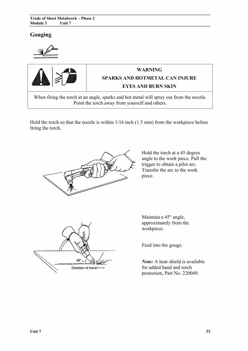
Gouging
WARNING
SPARKS AND HOTMETAL CAN INJURE
EYES AND BURN SKIN
When firing the torch at an angle, sparks and hot metal will spray out from the nozzle. Point the torch away from yourself and others.
Hold the torch so that the nozzle is within 1/16 inch (1.5 mm) from the workpiece before firing the torch.
Hold the torch at a 45 degree angle to the work piece. Pull the trigger to obtain a pilot arc. Transfer the arc to the work piece.
Maintain a 45° angle, approximately from the workpiece.
Feed into the gouge.
Note: A heat shield is available for added hand and torch protection, Part No. 220049.

Trade of Sheet Metalwork – Phase 2 Module 3 Unit 7
Unit 7 34
40 Amp Mechanised Shielded Consumables
Torch-to-work distance for the following cut chart is 1/16 inch (1.5 mm) for all cuts.
Table 4 - Cut Charts
Maximum travel speeds are the fastest travel speed possible to cut the material without regard to cut quality. Optimum travel speeds provide the best cut angle, least dross and best cut surface finish. Remember that cut charts are intended to provide a good starting point for each different cut assignment. Every cutting system requires “fine tuning” for each cutting application in order to obtain the desired cut quality.

Trade of Sheet Metalwork – Phase 2 Module 3 Unit 7
Unit 7 35
Parts
Torch Consumable Configurations
In CE countries, unshielded consumables may only be used in mechanised torch applications.

Trade of Sheet Metalwork – Phase 2 Module 3 Unit 7
Unit 7 36
Routine Maintenance
Figure 7 - Routine Maintenance

Trade of Sheet Metalwork – Phase 2 Module 3 Unit 7
Unit 7 37
Inspect Consumables
Figure 8 - Inspect Consumables
Trade of Sheet Metalwork – Phase 2 Module 3 Unit 7
Unit 7 38
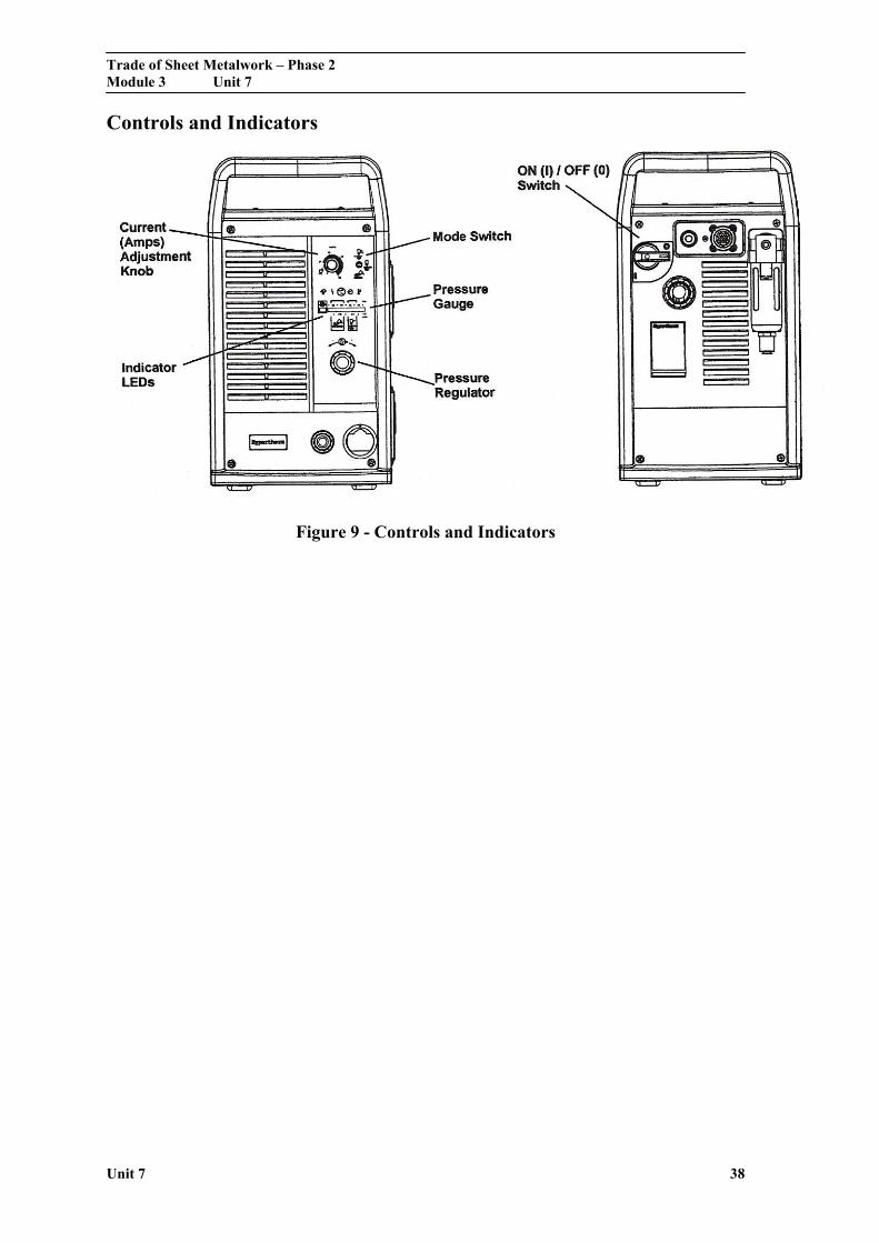
Controls and Indicators
Figure 9 - Controls and Indicators
Trade of Sheet Metalwork – Phase 2 Module 3 Unit 7
Unit 7 39
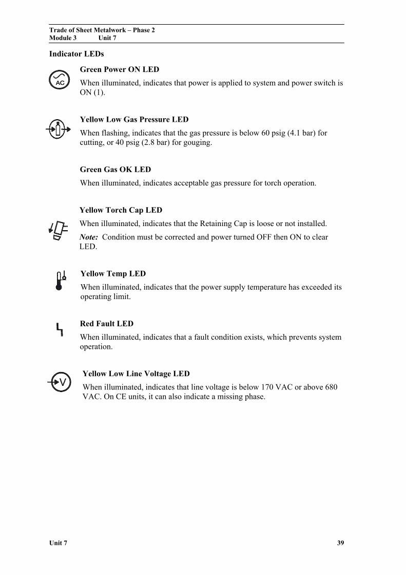
Indicator LEDs
Green Power ON LED
When illuminated, indicates that power is applied to system and power switch is ON (1).
Yellow Low Gas Pressure LED
When flashing, indicates that the gas pressure is below 60 psig (4.1 bar) for cutting, or 40 psig (2.8 bar) for gouging.
Green Gas OK LED
When illuminated, indicates acceptable gas pressure for torch operation.
Yellow Torch Cap LED
When illuminated, indicates that the Retaining Cap is loose or not installed.
Note: Condition must be corrected and power turned OFF then ON to clear LED.
Yellow Temp LED
When illuminated, indicates that the power supply temperature has exceeded its operating limit.
Red Fault LED
When illuminated, indicates that a fault condition exists, which prevents system operation.
Yellow Low Line Voltage LED
When illuminated, indicates that line voltage is below 170 VAC or above 680 VAC. On CE units, it can also indicate a missing phase.

Trade of Sheet Metalwork – Phase 2 Module 3 Unit 7
Unit 7 40
Basic Troubleshooting
Problem
1. The ON/OFF power switch is set to I (ON), and the POWER ON (GREEN) lamp is not illuminated.
Note: Fan on/off is automatic. Fan may not be in operation when power is ON.
2. The POWER ON (GREEN), LOW GAS PRESSURE RANGE (YELLOW) is flashing and FAULT (RED) lamps are illuminated.
3. The POWER ON, LINE VOLTAGE RANGE (YELLOW) and FAULT (RED) lamps are illuminated.
4. The POWER ON (GREEN), TEMPERATURE (YELLOW) and FAULT (RED) lamps are illuminated.
Cause / Solution
1.1 The power cord is not plugged into the power receptacle. Plug the power cord into the receptacle.
1.2 The disconnect power switch is not set to ON or there is no power available to the disconnect power switch box. Turn on the power at the main power panel or at the disconnect power switch box.
2.1 The gas supply is turned OFF or not connected to the power supply. Check that the gas is turned on and is connected to the power supply.
2.2 The incoming gas pressure is too low. Set incoming gas pressure to 90-120 psig /6.2-8.3 bar. Check that there are no leaks in the gas supply line.
2.3 Output gas pressure is set too low for selected mode. Adjust gas pressure.
3.1 Line voltage is too low, too high, or a phase (CE system only) is missing. Have a qualified technician check incoming power.
4.1 One of the internal thermostat switches has opened due to overheating or extremely low temperature. Leave the power supply on to allow the fan to cool the power supply (overheating). Move the power supply to a warm location (extreme cold).

Trade of Sheet Metalwork – Phase 2 Module 3 Unit 7
Unit 7 41
Problem
5. The POWER ON (GREEN), TORCH PARTS LOOSE OR REMOVED (YELLOW) and FAULT (RED) lamps are illuminated.
6. The arc does not transfer to the workpiece.
7. The arc blows out, but re-ignites when the torch switch is depressed again.
Cause / Solution
5.1 Retaining Cap is loose or removed from the torch.
Turn off power supply and tighten or install torch consumables.
If the torch consumables become loose or were removed while the power supply is on, turn off the power supply, correct the problem and then turn on the power supply to clear this fault.
6.1 The work clamp is not connected to the workpiece, or the work clamp is broken. Connect or repair the work clamp.
6.2 The work clamp is not making good metal-to-metal contact.
Clean the area where the clamp contacts the workpiece.
6.3 The torch is too far away from the workpiece.
Move the torch head closer to the workpiece and start the torch again.
7.1 The consumable parts are worn or damaged.
Inspect and change the consumables, as necessary.
7.2 The gas pressure is incorrect.
Adjust the operating gas pressure. Check that the gas pressure to the power supply is not less than 90 psig (6.1 bar) at a flow of 6 scfm (169 l/m).
7.3 The gas filter element outside the power supply is contaminated.
Replace filter element.

Trade of Sheet Metalwork – Phase 2 Module 3 Unit 7
Unit 7 42
Problem
8. The arc sputters and hisses.
9. Cut quality is not good.
10. The POWER ON (GREEN) and FAULT (RED) lamps are flashing.
11. The POWER ON (GREEN) and FAULT (RED) lamps are illuminated after power is turned on.
12. The POWER ON (GREEN) and FAULT (RED) lamps are illuminated for 10 seconds after trigger switch is activated.
Cause / Solution
8.1 The gas filter element outside the power supply is contaminated.
Replace filter element.
8.2 There is water in the air line.
Clean air filter or add additional air filtration to power supply.
8.2 Worn or incorrectly installed consumables.
Inspect consumables. Replace if necessary.
9.1 Consumables are worn or the torch is being used incorrectly.
10.1 Self diagnostic failure.
System needs repair.
11.1 Start signal ON when system power is initiated.
Turn start signal OFF. Turn power OFF and then ON again.
12.1 Consumables stuck or jammed.
Turn power OFF and Check consumables.

Trade of Sheet Metalwork – Phase 2 Module 3 Unit 7
Unit 7 43
Main Function Selection Menu
The FUNCTION SELECTION MENU is the starting point for all machine operations. At any time, during any operation, pressing the "RECYCLE" key aborts the current operation and returns to this top level of prompting.
When the "RECYCLE" key is pressed, the display sequences through:
"SELECT-FUNCTION"
"RUN- PROGRAM" (or last function selected)
"USE SCROLL-"
"-TO SELECT"
The "RUN PROGRAM" function is the default when power is applied to the 2.5RS. The default function then becomes the last function used. The other functions are selected with UP and DOWN scroll arrows or by pressing the appropriate number associated with that function. The selections are as follow:
KEY FUNCTION DESCRIPTION
1 RUN- PROGRAM Run the current program.
2 LOAD- STD. SHAPE Load from STANDARD SHAPE LIBRARY. Option must be enabled.
3 LOAD- FROM RS-232 Load from a RS-232 device.
4 STORE- TO RS-232 Store to a RS-232 device.
5 TEACH- PROGRAM Teach a program using an optical tracer.
6 DELETE- PROGRAM Delete a program from program memory.
7 EDIT / NEW-PROGRAM Create or edit a program.
. STORE TO FLOPPY Store to Floppy drive. Option must be enabled.
+/- LOAD FROM FLOPPY Load from Floppy drive. Option must be enabled.
3 SHF TWO KEY SEQUENCE
LOAD/RUN RS-232 Load from a RS-232 device and run immediately.
+/- SHF TWO KEY SEQUENCE
LOAD FROM FLOPPY Load from Floppy drive and immediately Run. Floppy option must be enabled.
Table 5 - Function Selection Menu

Trade of Sheet Metalwork – Phase 2 Module 3 Unit 7
Unit 7 44
FUNCMENU.l RUN PROGRAM
Once this function is selected, the prompt "PRGM=00000000" is displayed. At this point a different program number may be entered using the numeric keypad. The scroll keys may also be used to select a part in program memory. Press "ENTER" to select the program number.
The 2.5RS searches program memory for a part that has been assigned that number. If the part program exists, the run prompting begins. If the part program is not found, a "PGM NOT FOUND" error is displayed and program selection must be repeated.
FUNCMENU.2 LOAD-FROM STD SHAPE
Once this function is selected, the prompt "PRGM=00000000" is displayed. A program number is assigned to the selected GENERIC SHAPE to create a PART PROGRAM. A PART PROGRAM is a runnable program that resides in program memory. Enter a program number to be assigned to the GENERIC STANDARD SHAPE, (up to 8 digits) and then press "ENTER". The operator should select the desired shape from the following menu and go to the manual section indicated for that shape. The selection of a shape can be made either by scrolling to the desired shape or by entering the shape number on the keypad. Once the shape has been selected and the data entered, the shape is assigned the 8 digit program number for future reference.
The standard shape library contains 53 generic shapes.
FUNCMENU.3 LOAD-FROM RS-232
The "LOAD FROM RS-232" function is used to download a part program through the serial port into the 2.5RS memory. Once the function is selected, the prompt "PRGM=00000000" is displayed. Enter the program number to be used to store the part program data and press "ENTER". If the PROGRAM NUMBER selected does not exist, the operator is prompted for additional information pertaining to serial communication parameters.
If the program number requested already exists in program memory, then a special prompt appears:
FUNCMENU.4 "DUP PGM=########"
If a duplicate program error is given either enter a different number or go back and "DELETE" the existing program, then return to the "LOAD" operation.

Trade of Sheet Metalwork – Phase 2 Module 3 Unit 7
Unit 7 45
FUNCMENU.5 LOAD CUSTOM SHAPE FROM RS-232
Custom Shape Programs must be created by CMC, they are not customer programmable.
Custom Shape Programs are loaded using the same Serial loading method as normal Word address or ESSI programs. However, Program must be set to INTL for internal format type programs (this replaces the normal WADR or ESSI program format selection).
Custom Shape Programs have numeric me names (for example - 9892.CNC). However, once the program loads, it will appear as "BDF09892" in program memory to mark it as a special Binary Data Format Custom Shape program instead of a regular part program.
To use the custom shape, you must first "RUN' the program. Select RUN and scroll down to the program number "BDF09892" and press enter. The Running process will detect that it is one of the new custom shape programs and will set it up to be used. The display will change to "GENERIC XFER OK" which indicates the file has transferred to the standard shape memory correctly.
The display then changes to the normal prompt to "LOAD xxxxxxxx". This is the normal prompt for loading a program into memory. Enter the program number that you want to create and press enter. For example: "LOAD - 00000123".
The display then goes to the Shape Selection screen, and the custom shape number will appear as the first shape. For example, "SH9892-WELD". You can press Enter to select this shape, or you can use the scroll buttons or numeric keys to go through the list of standard and custom shapes. There can be more than one custom shape loaded at one time. For example, if you scroll down, the display will show Shapes 1 to Shape 53 and then go to SH9892. The custom shapes just appear as another standard shape at this point.
Enter the dimensions for the custom shape as usual, and then run the resulting part program as usual: RUN-00000123.
The normal "LOAD-FROM STD SHAPE" prompt will not access any Custom Shapes. If you run the Standard Shapes the usual way, the Custom shape will not appear in the list-you must go through the step of Running the BDF09892 program to get the GENERIC XFER OK message to make the Custom Shape active.
FUNCMENU.6 STORE-FROM RS-232
The "STORE FROM RS-232" function is used to upload a part from program memory out the serial port to a host storage device. Once the function is selected, the prompt "PRGM=00000000" appears. Enter the program number to be STORED to the remote device.

Trade of Sheet Metalwork – Phase 2 Module 3 Unit 7
Unit 7 46
FUNCMENU.7 TEACH-PROGRAM
The "TEACH" function is used along with the machines optical tracing system to "REMEMBER" an existing template and then repeat it any number of times without the template.
FUNCMENU.8 DELETE-PROGRAM
DELETE is used to erase a part program. Once the function is selected the prompt "PRGM=00000000" appears. At this point enter the number for the program to be deleted. The scroll keys may also be used to select a part in program memory for deletion. Press "ENTER" to DELETE the program.
All programs in program memory can be deleted by entering the program number "00000000" in response to the "PRGM= XXXXXXXX" prompt. When the ''ENTER'' key is pressed, a verification prompt is issued to make sure the operator is aware 'that all programs will be erased:
"YES ERASE ALL NO"
Pressing the "+/-" key toggles between a flashing "YES" and ''NO". To abort the function, press the "+/-" key so that the word "NO" is flashing and then press "ENTER". The control aborts the erase procedure and no programs are lost. To erase all the programs, press the "+/-" key so the word "YES" in the readout is flashing. Then press ''ENTER''. Again, since this procedure is irreversible, a second verification is given as:
''NO YOU SURE YES"
Notice that to erase all the programs, the "+/-" key must be pressed twice again. This minimises the chances of an accidental erasure. Pressing the "ENTER" key, with the ''NO'' flashing aborts the process. If the "YES" response is selected, the programs are erased and the readout displays:
"PROGRAMS DELETED"
FUNCMENU.9 EDIT/NEW-PROGRAM
The EDIT /NEW function allows the EDIT of a part program that resides in program memory. It may be altered in any way. The EDIT/NEW function also allows for the creation of a new part. For a detailed description of the "EDIT/NEW- PROGRAM" function see section "EDITOR".

Trade of Sheet Metalwork – Phase 2 Module 3 Unit 7
Unit 7 47
FUNCMENU.10 STORE- TO FLOPPY
The "STORE- TO FLOPPY" selection is used to save a part program to a floppy disk. If the control has an internally mounted disk drive, the program is stored there. If the control does not have an internal disk drive, and an external portable floppy drive is connected to the serial port, the selected program is saved to the external floppy drive.
FUNCMENU.11 LOAD FROM FLOPPY
The "LOAD FROM FLOPPY" selection is used to load part programs from a floppy disk. If the control has an internally mounted disk drive, the program is loaded from there. If the control does not have an internal disk drive, and an external portable floppy drive is connected to the serial port, the selected program is loaded from the external floppy drive.
FUNCMENU.12 LOAD/RUN RS-232
Use "LOADIRUN RS-232" to load a part program from the serial port, and immediately run that program. The 2.5RS can also automatically delete the program after cutting, and load the next program.
FUNCMENU.13 LOAD/RUN FROM FLOPPY
Use "LOAD/RUN FLOPPY" to load a part program from a floppy and immediately run that program. The 2.5RS can also automatically delete the program after cutting, and load the next program.

Trade of Sheet Metalwork – Phase 2 Module 3 Unit 7
Unit 7 48
Shape.1 Shape Selection
The "LOAD- FROM STD. SHAPE" function allows the operator of the 2.5RS to select a generic part from the STANDARD SHAPE LIBRARY and create a part program.
Press the "ENTER" key. The display changes to "LOAD- 00000000". This is the PART PROGRAM NUMBER that will be assigned to the selected GENERIC SHAPE when the part dimensions are entered. Once a program number is entered the shape selection process begins.
The 2.5RS shape library contains 5O SHAPE PROGRAMS which are referenced by "SHAPE NUMBER". The operator must first select the desired shape from the following chart either using the scroll keys or by entering the desired number directly. Once the correct number and name are displayed, press the "ENTER" key to select the shape.
Detailed drawings of each shape are located at the end of this section. These give additional information about the various options for each shape and illustrate the required dimension inputs.
The STANDARD SHAPE programs are written in a "GENERIC" format which describes the shape of the part but leaves the part dimensions variable. Once the shape has been selected, the operator is required to answer a series of prompts which determines the final dimensions of the part. The individual shape drawings at the end of this section help to illustrate the various dimensions. These drawings should be referred to when answering the various prompts.
If a dimension is requested, use the numeric keypad along with the decimal point and "CE" or "CLR" keys to enter the desired value. Once it is correct, press "ENTER". Since the 2.5RS can operate in either a metric or inch system, the standard units for the dimensions are those selected for the operating system during installation by "SD60". However, dimensions can be entered in either unit by using a special key sequence. In this way, an occasional metric part can be entered directly even though the system is set for inch units.
To enter a dimension in the opposite unit from the system default, press the "SHIFT' key first. The displayed value is converted to the opposite unit (inch/mm) and the number of decimal places will change (2 for inch, 1 for mm). Pressing the same key again changes the value back to the original units. This key only changes the value being entered and does not switch the units for the entire system. Each dimension must be converted individually as required.
If a count (such as number of holes) or other integer value is requested, use the numeric keypad and clear key to enter the desired number. Once the value is correct, press "ENTER".

Trade of Sheet Metalwork – Phase 2 Module 3 Unit 7
Unit 7 49
2.5RS Operation and Maintenance Manual
If a selection such as CW/CCW, YES/NO etc. is requested the displayed response may be toggled by using the "+/-" key. Press "ENTER" when the correct response is displayed. If a start point or repeat direction is requested, use the outside row of keys on the numeric keypad 1-9 to indicate the correct corner or direction. Once the correct direction is indicated on the readout, press ENTER. Invalid entries for a particular prompt are ignored.
Start point or repeat direction:
Figure 10 - Outside Row on Keypad
Once all the prompts are answered, a verification prompt appears, "YES+ VERIFY +NO". To verify the input data, which starts the prompting over again, press the "+/-" key one time causing the "YES+" to begin flashing. Then press the "ENTER" key to review the input data. Use the "ENTER" key to step through the prompts, and correct any values as needed.
After all prompts have been answered correctly, the 2.5RS creates the part program. The following prompts are displayed:
"* COMPUTING *" The input data is being processed.
"PROGRAM LOADED" The program has been created.
Press RECYCLE to return the MAIN FUNCTION MENU. Go to "RUNNING THE PART' in this manual for directions on actually running the program.
Trade of Sheet Metalwork – Phase 2 Module 3 Unit 7
Unit 7 50
Shapes.2 Dimensions Common to Most Shapes
In addition to the actual dimensions of the part, most of the 53 SHAPE PROGRAMS also prompt for the following:
KERF
SCRAP
LEADIN
LEADOUT
The standard shapes also prompt for a "KERF" value along with the part dimensions. Since all controls are now equipped with the optional “Dial-in-Kerf” feature, the value of 0.00 should be entered for the KERF prompt during the dimension entry (See exceptions below). By entering 0.00 at this point, the “Dial-in-Kerf” feature can be used when the part is actually cut to enter and adjust the kerf dimension as needed. If a KERF value other than 0.00 is entered during the dimension prompting of a standard shape, it is permanently added to the part dimensions, and the “Dial-in-Kerf” feature is bypassed when the part is cut thus the kerf cannot be adjusted and the entire part must be re-entered to change it.
NOTE
On any "Chain Cut" parts, such as the WEDGE PAIR or CHAIN RECTANGLE, the kerf must be entered along with the part dimensions during the program creation. This is due to the common side cutting and nesting which is done on these parts. Regardless of the kerf entered, the "DIAL-IN-KERF' will not function on these parts.
Most of the standard shapes also prompt for a "SCRAP" dimension. This is the space left between successive rows of parts. Since the “Dial-in-Kerf” feature does not increase the part-to-part spacing, the value for "SCRAP" must allow for enough material to accommodate the anticipated KERF plus the desired amount of actual material to be left between the rows of parts.

Trade of Sheet Metalwork – Phase 2 Module 3 Unit 7
Unit 7 51
2.5RS Operation and Maintenance Manual
The "SCRAP" value provides the spacing between parts as they are repeated down the plate. The accuracy of this scrap dimension is just as good as the actual part itself; therefore the value can be set fairly small with good results. Typical "SCRAP" value for OXY/FUEL CUTTING can be anywhere between .1" to .5" (2.5 mm to 12 mm). Note that the "SCRAP" dimension must allow for the anticipated cutting kerf if the "Dial-in-Kerf' feature is to be used when the part is cut.
The "LEADIN" dimension is the distance from the part to the pierce point. Since the piercing operation is sometimes unpredictable, the leadin dimension should be set so that the plate is pierced and the cut has stabilised before it reaches the actual part. Normal values range from .25" to 1.00" (6mm TO 25mm).
The "LEADOUT" dimension is programmable for each of the standard shapes, and causes the torch to cut away from the part before the cutting oxygen is turned off. This prevents any damage to that part due to the bleed off characteristics of the torch. In addition, on heavy plate cutting, the leadout move guarantees that the bottom of the part has been cut completely before the oxygen is turned off. Normal values are from .5" to 1" (12mm to 25mm).
For plasma systems, the "LEADOUT' should be adjusted to properly time the turn-off of the arc. If the leadout is too long, cut parts will fallout of the plate and cause an abrupt turn off of the torch. This will cause attempts to restart the plasma, and thus excessive wear on torch parts.

Trade of Sheet Metalwork – Phase 2 Module 3 Unit 7
Unit 7 52
Figure 11 – Shapes
Standard Shapes
* Selectable start position, cw/ccw cutting, and selectable repeat mode and direction.
Shapes 51, 52 and 53 are enhanced versions of shapes 1, 2 and 3.
** Allows selection of any number of holes.
*** Dashed holes are optional. Corner radius values may be set to 0 for sharp corners.

Trade of Sheet Metalwork – Phase 2 Module 3 Unit 7
Unit 7 53
Self Assessment
Questions on Background Notes – Module 3.Unit 7
1. Name two shielding gases used in plasma cutting.
2. List the five conventional consumables used for plasma cutting.
3. List three hazards associated with plasma cutting.

Trade of Sheet Metalwork – Phase 2 Module 3 Unit 7
Unit 7 54
4. Describe how you would cut a piece of metal with the plasma hand held torch.
5. Describe how you would pierce a piece of metal.

Trade of Sheet Metalwork – Phase 2 Module 3 Unit 7
Unit 7 55
Answers to Questions 1-5. Module 3.Unit 7
1.
Air C02 Oxygen-nitrogen Air-methane Nitrogen Methane
2.
3.
Fire or explosion Electric shock Toxic fumes Arc rays Noise Compressed air hazards and magnetic fields may affect
pacemakers / hearing aids.
Electrode Swirl ring Nozzle Retaining cap Shield

Trade of Sheet Metalwork – Phase 2 Module 3 Unit 7
Unit 7 56
4.
1. Attach the work clamp securely to workpiece.
2. Ensure good electrical contact.
3. Hold torch nozzle vertical at edge of workpiece.
4. Start cutting from the edge of the workpiece, pause at
the edge until the arc has completely cut through the
work piece.
5.
1. Hold the torch so that the nozzle is within ⅛ inch (3mm)
from the workpiece.
2. Fire the torch at an angle to the workpiece and then slowly
rotate it to an upright position.
3. When sparks are exiting from the bottom of the workpiece
the arc has pierced through the metal. When the pierce is
complete continue with the cut.

Trade of Sheet Metalwork – Phase 2 Module 3 Unit 7
Unit 7 57
Index
A Adjust Gas Pressure and Current Setting, 31
C Check Indicator Lights, 30 Consumables, 15
Installing Consumables, 15 Recording Consumable Life, 16
Controls and Indicators Indicator LEDs, 42
G Gas Selection, 13
Plasma Gas, 13 Selecting the Right Gas, 14 Shield Gas, 13
H Hand Torch Operation, 32
40 Amp Mechanised Shielded Consumables, 37 Attach the Work Clamp, 33 Gouging, 36 Hand Torch Cutting Technique, 34 Piercing, 35 Safety Trigger Operation, 32 Starting a Cut from the Edge of the Workpiece, 33
I Installing Torch Consumables, 28
M Main Function Selection Menu, 46 Mode Switch, 30
P Parts, 38
Basic Troubleshooting, 43 Controls and Indicators, 41 Inspect Consumables, 40 Routine Maintenance, 39 Torch Consumable Configurations, 38
Plasma, 11 Cutting with Plasma, 12 Plasma Definition, 11 Plasma in Nature, 11
S Safety, 17
Additional Safety Information, 24 Warning Label, 25
Self Assessment, 57 Shape.1 Shape Selection, 52
2.5RS Operation and Maintenance Manual, 53 Shapes.2 Dimensions Common to Most Shapes, 54
2.5RS Operation and Maintenance Manual, 55 Symbols and Markings, 27
IEC Symbols Used, 27 S Mark, 27
T Turn ON Power, 30