introduction to microscopes chapter 1 - campbell university · 2018-08-21 · introduction to...
TRANSCRIPT

Introduction to Microscopes Chapter 1
Objectives
1. Know the parts of the microscope and their functions. 2. Understand proper use of a microscope and apply these skills. 3. Properly prepare wet mounts.
Background The compound light microscope is an essential instrument in biology laboratories and in
research. Microscopes have many applications; they may be used to view the location of a particular protein inside of a cell, to explore individual cellular structure or employed at the body structure level (in dissection or examination of various multi-cellular organisms). As with the many different applications for microscope usage, there is a variety of diverse microscopes as well where the design dictates the specific function. What each microscope has in common is the ability to aid humans in visualizing organisms and cells that cannot be seen with the naked eye. Microscopes contain something (normally a series of lenses) that focuses light (or other energy which is then translated into a regular ‘light’ image) and magnifies the images that are placed on the viewing area of the microscope.
Most laboratories make use of common compound light microscopes that are binocular. In the same way that field binoculars with two eyepieces are used by biologists and hunters to focus on objects at a distance, again the binocular microscope means that it has two eyepieces that are used to magnify and focus on objects too small to see with the naked eye. In this view the two eyepieces must be adjusted for distance between a person’s eyes, known as the interocular distance. Microscopes that are compound contain more than one lens system used for magnifying the image. The microscopes in the lab today will contain the objective lens and also an ocular lens that both participate in magnification.
Although a dissecting or stereo microscope is a type of light microscope also frequently employed in laboratories, the lab sessions in basic biology will only handle the compound light microscopes. Only thinly sliced objects on slides may be utilized with the compound light microscopes. Dissecting microscopes view larger, thicker specimens than the compound light microscopes can accommodate.
NOTE: Always READ the text of this lab manual in order to complete the Student Data Sheets. The Student Data Sheets are answer sheets only, for the most part. Follow this text while doing each activity in the lab. Listen for any changes the lab instructor may speak, point to or show and note them in the appropriate areas.
Lab Activities:
I. Parts of the Microscope II. Care and Use: letter ’e’ practice III. Wet-Mount Preparation and Use (graded skill activity) IV. Calculations & Measurements
5

I. Parts of the Microscope:
A. Prior to lab session, review and learn the location and function of the important parts of the microscope.
Parts of the compound light microscope are listed in Appendix (Chapter 1). Figure 1.5 of the Student Data Sheet (SDS) is an image of a compound light microscope that can be used while studying the parts (& part functions) of the microscope prior to lab. Also, each student will need to examine the microscope that is assigned to them once in lab. There are different models of microscopes, therefore do not be surprised if a part or two on the assigned microscope is different from the figure.
B. In lab, write down the NAME OF EACH MICROSCOPE PART on top of the corresponding box/line that points to that component: use Figure 1.5 of the Student Data Sheet (SDS).
Use the information provided in the Appendix Chapter 1 to decide to which part each arrow is pointing.
C. In lab, write down the FUNCTION OF EACH PART, inside the box space below on top of which students are to place the part name on Figure 1.5 of the SDS.
Use the information in the Appendix Chapter 1 to determine the function of each microscope part as depicted in the diagram.
II. Care and Use of the Microscope. A. Care of the Microscope.
1. Obtaining, moving and storing the microscope [REFER BACK TO THIS LATER AS WELL]:
5 point deduction for each misuse of the microscope: Please note that the lab instructor will implement this especially for failure to adhere to the following…
Use two hands to pick up the microscope. Use one hand to grasp the arm of the microscope the other hand should be firmly placed under the base.
Always return to 4X objective (scanning) position over stage opening before returning the microscope to the storage cabinet.
In addition, always revolve it to 4X when a slide is placed on or removed from the stage. Wrap cord around the microscope properly. On the Parcos, wrap around the lower arm, as in Fig. 1.5. (see ‘d’).
Cover the microscope prior to storage with its correct dust cover.
The correct microscope cabinet slot number corresponds to the number located on the back of the lower arm of the microscope. Return in to this slot.
• However, always check with the instructor prior to carefully sliding the microscope into the microscope cabinet!
Write the microscope number in two places (this is the semester’s assignment):
• ASSIGNED MICROSCOPE NUMBER: ___________. • Record on the SDS as well (see II.A.1.).
6

2. Lens cleaning and slide cleaning [REFER BACK TO THIS LATER AS WELL]:
Gently clean, BEFORE and AFTER using the microscope for each lab, ALL oculars, objectives, and pre-made slides.
Use lens paper only. (Do NOT use paper towels or Kim wipes!)
Oculars—please pay special attention to clean these.
Others using the microscope may have smudged the ocular lenses with their skin. • Oil from the skin may cause the lenses to appear blurry. Eye makeup, this may
also get onto the ocular lens and must be cleaned appropriately.
• As microscopes are shared between lab sections, these typical items may occur to your assigned microscope from week to week.
High power (40X) objective— please pay special attention to clean these.
Some substances will often adhere to the high objective lens (as well as the stage and the condenser lens): • Staining reagents (methylene blue, iodine) or • Salt water on samples.
Ask for some glass cleaner from the instructor. • Spray a little glass cleaner on a piece of Lens Paper and never directly on the
objective or ocular lens, • wipe the lens, wiping dry with a dry corner or a new Lens Paper.
B. Proper microscope use. Letter ‘e’ Exercise.
1. Placement of the Microscope:
Place the microscope directly in front of oneself, with oculars facing toward oneself.
The student sits directly in the seat well.
Legs are placed directly forward in the seat well.
Try adjusting the seat so that the eyes are about a centimeter above the ocular lenses.
• The adjustment in height is necessary so that each student is not stooping or stretching to see into the microscope.
If a student wears glasses, pay careful attention not to scratch them on the oculars, or consider not using them when viewing through the microscope.
• Almost everyone is able to use the microscope without using glasses.
Plug the microscope cord into an outlet nearby/ just under the benchtop.
7

2. Binocular View:
Adjust the INTEROCULAR DISTANCE:
To use a microscope properly, one must look through the eyepieces with both eyes. Adjust the Interocular/Interpupillary Distance (ID)(corresponds to the distance between the pupils of both eyes).
• Move the eyepieces either closer to one another or further apart from one another, while looking into both ocular lenses (Grasp at the ridged areas—see ‘a’ on Figure 1.6 of the Body Tube/Head of the Microscope).
• The goal is to change the distance between the two eyepieces UNTIL ONLY ONE FIELD-OF-VIEW (CIRCLE) IS SEEN INSTEAD OF TWO. This must be done before going on.
Determine the numerical value for this distance.
Each microscope has a numerical scale located in between the two eyepieces. Write down this ID value in two places once found.
• The INTEROCULAR DISTANCE (ID) for personal assigned microscope: ______. • Record this number onto the SDS (II.B.2.) as well.
Pointer: Also do not be surprised that, as one looks through the oculars, one of them has a pointer which looks like a black hair-line extending about half way through the view.
For the Non-Siedentopf head microscopes (most of the intro microscopes), an additional step is needed: Rotate the eyepieces on the ocular lenses until they are set to the SAME numerical amount as the just determined ID above.
Examine the eyepieces on the assigned microscope. Each one can be rotated either clockwise or counterclockwise by grasping those ridged areas (see ‘b’ on Figure 1.6).
And when rotated, a line appears to the outer side of each rotating eyepiece’s fixed portion on the body tube/head (approximately where near where ‘c’ is on Figure 1.6, it will appear on eyepiece where it sits upon the body tube/head).
Using this procedure, use the ID number the student obtained previously and
• By rotating the eyepiece, match that numerical amount now to the line (see ‘c’ on Figure 1.6) that appears, one-ocular-at-a-time.
After eyepieces are adjusted for ID number, the microscope may be “fit” for differences in eye strength for each eye. Please ask the instructor for directions.
If waiting for other students in order for the class to continue on, the student may go to “Section IV.A. Calculate the Total Magnification”. Complete just that section.
8

3. Scanning (4X) objective use:
Turn the nosepiece until the 4X scanning objective clicks in place (shortest objective).
Always begin with the SCANNING objective lens (NOT LOW and NOT HIGH), and end with the scan objective when removing a slide (or placing slide under objectives).
Place the slide onto the stage:
Obtain a pre-made letter ‘e’ slide from the preparation table. Place the slide into the movable slide holder/mechanical specimen device (see directions, Appendix Chapter 1, for mechanical stage) and, using the knobs, move the slide until ‘e’ appears to be directly above opening in stage. Do not look through the lenses.
Make sure that while sitting in the chair the letter ‘e’ still appears as a correctly oriented readable ‘e’. This means that when NOT yet looking into the microscope eyepieces, the student should see with the naked eye the letter ‘e’ on the stage in the normal readable position, that is, ‘e’.
Focusing the specimen should be done as follows:
Move the stage all the way up vertically using the Coarse Adjustment.
Before looking into the eyepieces, grasp and slowly turn the Coarse focus until the stage with the slide is moved as close to the nosepiece and the scan objective (4X) as is allowed. On scan (4X) objective, ONLY Coarse Adjustment may be used!
Now it is finally time to focus the specimen.
Look into the eyepieces. The Coarse adjustment/focus knob should turn in only one direction since the stage was previously moved all the way up in the other direction.
Slowly turn the Coarse adjustment knob until the object begins to come into focus. Continue turning until the object (the letter ‘e’) is sharply in focus.
Use the Movable Slide Holder Knobs (usually on the back right, just under the stage) to move the ‘e’ into the center of the field of view, if it is not already there.
• The goal is to have the letter ‘e’ centered on the stage directly over the center of the hole for the incoming light (over the condenser lens center). (A student may use the naked eye to do this since the letter ‘e’ is very large and visible.)
• Note: Just to make sure that it is not dust on the top of the slide the student focused on (instead of the real specimen), perhaps continue to slowly turn the Coarse focus knob—instead of failing to move the focus far enough to see the specimen itself! One may always move the coarse focus backward again.
• One may always start over again –turn the stage upward so that it is closest to the nosepiece once more, and so on. THIS IS THE TIME TO PRACTICE!
9

4. Practice adjusting the light intensity while viewing under the scanning (4X) objective:
Look around the side of the condenser until the index finger is easily placed on the iris diaphragm lever.
DO NOT SIMPLY FEEL AROUND FOR IT, AS ONE WILL MOST LIKELY DISLODGE THE CONDENSER BY MISADJUSTING THE SILVER SCREWS INSTEAD.
Remember that it is a LEVER, and not a knob!
Slide the diaphragm lever back and forth while looking through the eyepieces and notice what effect the changing light intensity has on the clarity of the letter ‘e’.
When changing from lower to higher power objectives, students will almost certainly need to adjust the light intensity as well. (Also see II.B.3.)
(BUT have the Rheostats (on those microscopes that have them) dialed up to the highest amount of light at all times in this course!)
5. Sketch the letter ‘e’ .
Once the specimen is in focus, turn to the Student Data Sheet:
Sketch how the ‘e’ appears to a student, in the Center of the field of view, while looking through the eyepieces and using the scanning (4X) objective.
6. Low power objective (10X)—Switch to this view.
Do NOT use the coarse adjustment to move the stage when preparing to turn to the next objective. After viewing, centering and focusing the specimen under scan, do not make any adjustments such as moving the stage up or down.
Simply rotate the nosepiece to the low power 10X objective. These microscopes should be parfocal. Each objective lens is aligned in focus so that only minor adjustments, after the objective is changed, need be made for specimens to be in focus.
Look through the eyepieces. Use the Course adjustment to bring the specimen into focus. A student should have to turn the Course adjustment only a tiny amount now, else the item will be destroyed. (With wet mounts later, this may be where mistakes are made.)
Once the specimen is in focus, turn to the Student Data Sheet:
Sketch how the ‘e’ appears when using the Low power 10X objective.
Remember that light intensity may need adjustment using the diaphragm lever/disc.
Has the student placed a dark part of the letter ‘e’ in/moved it to the direct center of the field of view (FOV) in preparation for the high power objective? This adjustment is necessary due to FOV changes as one switches between objectives. See the Appendix for the FOV definition and also the later activity.
10

7. High power 40X objective—Switch to this view. Use the same technique as described
previously for the low power (10X) objective use. Use only FINE FOCUS with high power.
Again, the microscope is parfocal. Do NOT move the focus knobs while switching objectives (or between switching)! Simply rotate the high power objective into place. The only reasons this may not work are 1) slide is stuck together with another and
the ‘slide’ is therefore 2-slides-thick; 2) specimen is too thick (as in later potato lab).
Use the Fine focus/adjustment to bring the specimen into focus for the high power objective. One should NOT have to turn the fine adjustment too far. Adjust diaphragm lever/disc to change the amount of light.
Sketch what is seen when viewing the letter ‘e’ with the high power (40X) objective in the Student Data Sheet. If nothing is seen, move back to low power, place part of the ‘e’ in the center of the field of view, then move to high power and focus and sketch it.
III. Wet-Mount Preparation and Use. (Instructor will assess student’s wet mount today. A. Preparing a wet mount:
1. Obtain a clean glass slide and a cover slip from the group’s lab table. 2. Add a drop of water to the slide from the dH2O dropper at the group’s lab table. Make sure
to keep the slide horizontal at all times. 3. Obtain a small portion of Spirogyra algae.
A couple to a few filaments using forceps is correct—they look like thin pieces of hair. • A ‘gob’ of algae will NOT work. Add to the normal water on the slide.
4. Place the cover slip onto the slide using the proper technique:
Carefully hold a cover slip so that it is at an angle (45°) to the slide itself (Figure 1.1). That is:
• Holding the cover slip by its mid/bottom edges, nearer to one edge of a slide, gently this end of the cover slip down towards the glass slide. Then slowly push the mid/bottom of the cover slip along while still grasping it by its sides at that angle compared to the slide surface (about 45°) until the bottom of the cover slip encounters the water.
• Important: Do not actually press the cover slip down horizontally at all on the slide as it is pushed along. The plastic coverslips are malleable and easily bend if pressed! Squished organisms result, once the process is complete. Not good.
• Carefully & slowly drop the rest of the cover slip onto the slide. Do not let the initial side of the cover slip (that is already on the glass slide) rise up out of the water.
Start near this end
Figure 1.1
Grasp cover slip on either side and push along gently at a 45% angle compared to the slide surface angle
11

Dropping the cover slip using the 45o angle approach normally prevents air bubbles from being trapped under the cover slip.
• Air bubbles will be trapped beneath if the cover slip is dropped parallel to the slide.
Remove any water from the bottom of the slide (Most Important) by carefully placing it ON a paper towel.
NEVER TAP the cover slip since this might ‘squish’ the specimen and distort or completely destroy it. DO NOT TOUCH THE TOP OF THE COVER SLIP at all.
• Remove any water from around the cover slip by carefully blotting with pieces of paper towel—but only do this if excessive.
(Less Likely: ask for help prior to attempting this.) Remove excess water from between the cover slip and the slide.
• If, for instance, it looks like a ‘raft on an ocean’, place a piece of paper towel beside the edge of the cover slip until it encounters the water.
• Quickly remove the paper towel once it has removed enough water—do not allow it to remove too much.
• Also add a drop of water to the side of the cover slip if it is now too dry underneath the cover slip. Remember never tap the cover slip!
B. Observe the student’s prepared Spirogyra wet-mount by using the light microscope.
View the new Spirogyra wet mount using the same methods as for the pre-made letter ‘e’ slide. This means starting with the scan (4X) objective, then the low power (10X) objective, then lastly, the high power (40X) objective.
As one turns from scan to low to high power, note what happens to the field of view (FOV) as seen through the microscope. Review the FOV definition in the Appendix.
Document this in the SDS (III.B.).
As one turns from low to high power, note what happens to the intensity of light as seen through the microscope.
Document this in the SDS (III.B.).
C. Practice the Spirogyra wet mounts preparation/assessment. Personal technique/wet mount is assessed in the lab by the instructor.
Practice making wet-mounts from scratch & then obtain one that:
• Has no air bubbles (or very few)
• Has correct amount of water
• Is centered and in focus.
→ Practice bringing the specimen of Spirogyra into perfect view under High power for grading.
12

→ The personal assessment will be how close each student is to obtaining all these goals → When the student’s slide has met these conditions, notify when ready for grading (III.C.)
IV. Calculations & Measurements.
A. Calculate the Total Magnification:
The total magnification is the entire amount that the object’s actual size is increased (magnified) when viewing under the microscope. See the Background concerning the ‘Compound Light Microscopes’ we are using today in lab.
Total Magnification = Magnifying Power of the Ocular x Magnifying Power of the Objective.
OR Total Magnification = Ocular Magnification x Objective Magnification
Notice that the two magnifying powers are multiplied together, not added together.
Remember that most oculars, such as with today’s microscopes, have a magnifying power of 10X (makes the object look ten times larger than it is seen with the naked eye).
Complete the calculations for total magnification on the Table 1.1 (SDS).
Also go back to the letter ‘e’ exercise II.B. and fill in the ‘Total Magnifications’ on the SDS.
B. Measure the Field-of-View (FOV) of each Magnification:
The purpose of measuring the FOV for each objective is that it will then allow each student to calculate the actual size of the objects seen in the FOV for each magnification.
Begin with the scanning objective FOV.
Place a plastic ruler under the movable specimen holder arms (see Figure 1.2 below) so that it can be seen easily in the field-of-view when looking into the microscope oculars.
Make sure to use the METRIC side when viewing the ruler.
The goal is to measure the diameter of the field-of-view.
|IIII|IIII|IIII|IIII|IIII|IIII|IIII|IIII|IIII|IIII|IIII|IIII|IIII|IIII|IIII|IIII|IIII|IIII|IIII|IIII|IIII|IIII| 1 2 3 4 5 6 7 8 9 10 cm
11
Placing ruler under the stage holder arms (may look different than these), over light opening in stage
Figure 1.2. View as one looks from outside the microscope—looking down onto the stage
13
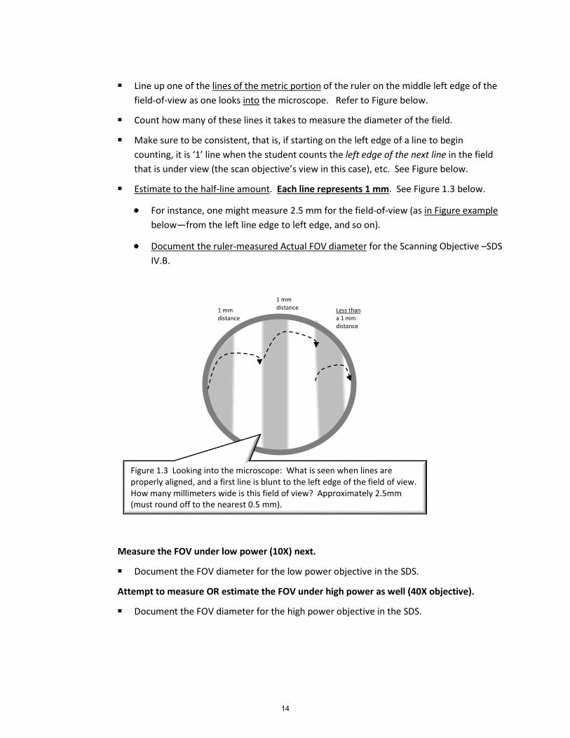
Line up one of the lines of the metric portion of the ruler on the middle left edge of the
field-of-view as one looks into the microscope. Refer to Figure below.
Count how many of these lines it takes to measure the diameter of the field.
Make sure to be consistent, that is, if starting on the left edge of a line to begin counting, it is ‘1’ line when the student counts the left edge of the next line in the field that is under view (the scan objective’s view in this case), etc. See Figure below.
Estimate to the half-line amount. Each line represents 1 mm. See Figure 1.3 below.
• For instance, one might measure 2.5 mm for the field-of-view (as in Figure example below—from the left line edge to left edge, and so on).
• Document the ruler-measured Actual FOV diameter for the Scanning Objective –SDS IV.B.
Measure the FOV under low power (10X) next.
Document the FOV diameter for the low power objective in the SDS.
Attempt to measure OR estimate the FOV under high power as well (40X objective).
Document the FOV diameter for the high power objective in the SDS.
Figure 1.3 Looking into the microscope: What is seen when lines are properly aligned, and a first line is blunt to the left edge of the field of view. How many millimeters wide is this field of view? Approximately 2.5mm (must round off to the nearest 0.5 mm).
1 mm distance
1 mm distance Less than
a 1 mm distance
14

C. Calculate the size of the letter ‘e’:
• DO NOT USE THE RULER ON THE MICROSCOPE at the same time as the ‘letter e’
• Now that FOV for each objective has been measured, the real size of a specimen (letter ‘e’) will be able to be calculated.
1. Estimate the size of Letter ‘e’ first
Low Power (10X) objective only
Use the proper technique for finding the letter ‘e’ on the microscope.
• First find the letter ‘e’ using the scan (4X) objective (remember to place it near the center). Next rotate the nosepiece and immediately find the letter using the low power objective.
Estimate how much of the “diameter of the view (FOV)” that the letter ‘e’ takes up.
Does it take up the entire FOV diameter or a fraction of the FOV diameter? • such as ½, ¼, 1/3,1/8, 4/5 or even 1 (the entire) of the FOV diameter? • Hint: when estimating, center the letter ‘e’ in the field of view and • then move the letter ‘e’ so that it is touching one side of the field of view. This
will allow the best estimate. Do not leave it in the center!
• Answer on SDS IV.C.
2. PUTTING TOGETHER THE NUMBERS IN THE CALCULATION.
Multiply the estimated fraction of how much of the FOV that the letter ‘e’ encompasses (IV.C.) by the FOV measured size (from section IV.B.). Use Low Power Objective measurement only.
This value will be in mm of the view. (Student Data Sheet IV.C.).
The proportion of the FOV diameter that letter ‘e’ takes up (estimate) x measured Low Power FOV = real size of letter ‘e’
• As an example: estimate that the letter ‘e’ is 1/8 of the diameter (0.125 of the diameter). See text direction, no. IV.C. above.
• Multiply by the measurement already made with the ruler of the diameter of the FOV on Low power, for example 7.5 mm diameter. (See text direction, no. IV.B., previous page.)
• 0.125 x 7.5 mm = 0.94 mm actually how large the letter ’e’ is on the slide in this example. Round to only 1 or 2 decimals.
15

16

Biology 111 L Introduction to Microscopes Name ________________________ Chapter 1 STUDENT DATA SHEET Lab day & time _________________
Lab Section no. _____
I. A., B., C. Parts of the Microscope. REMEMBER TO READ AND FOLLOW THE LAB TEXT DIRECTIONS. Figure 1.5: The Compound Light Microscope.
Stage
Body Tube/ Head
d
Do not loosen the bolt or screw
Condenser adjustment knob
Please do not loosen the bolt or screw
Condenser
Base
Rheostat on side (Light intensity control knob)
Condenser lens
Lab Sheets score: _____ Wet Mount score: _____
17

Figure 1.6 Body Tube (head) of Microscope with labels. a) Gripped areas used to grasp to widen or shorten when determining interocular distance (ID). b) Gripped areas of oculars used to rotate when adjusting oculars to match the ID. c) Point on the stationary axis of body tube where the line will appear once the ocular is rotated. Used when matching oculars to ID.
b
a a
c c
18