introduction midas gen & integrated solutions basic tutorial · 2016-09-17 · step midas gen...
TRANSCRIPT

Step
midas Gen & Integrated Solutions
Introduction
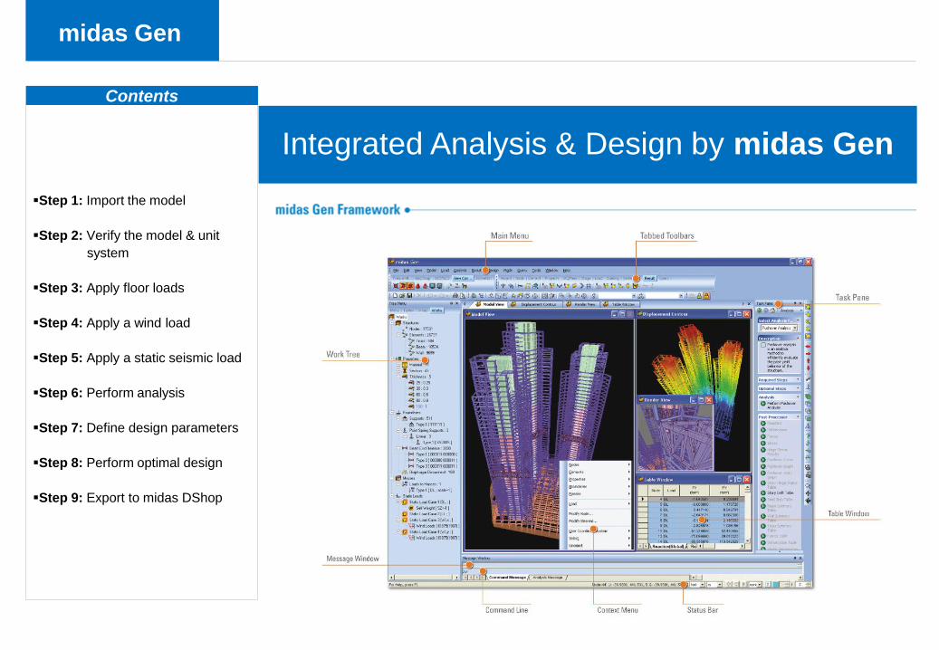
Integrated analysis & design by
midas Gen
- Import the model from midas
Modeler
- Apply wind loads, seismic loads,
etc.
- Analyze & design the model
- Export model to midas DShop for
structural drawings
Auto-generation of structural
drawings & B.O.M. by midas
DShop
- Import the optimized design
model from midas Gen
- Edit reinforcements
- Auto-generate the Bill of
Materials
- Auto-generate structural drawings
midas Gen & Integrated Solutions
Basic Tutorial
This tutorial will demonstrate a one process solution for buildings from modeling, to analysis
and design, to structural drawings using midas Gen & Integrated Solutions.
DWGs midas Gen midas DShop

Step
midas Gen & Integrated Solutions Overview
3D Model View Framing Plan
Perspective View
midas Gen
Contents
Step 1: Import the model
Step 2: Verify the model & unit
system
Step 3: Apply floor loads
Step 4: Apply a wind load
Step 5: Apply a static seismic load
Step 6: Perform analysis
Step 7: Define design parameters
Step 8: Perform optimal design
Step 9: Export to midas DShop
Integrated Analysis & Design by midas Gen
midas Gen
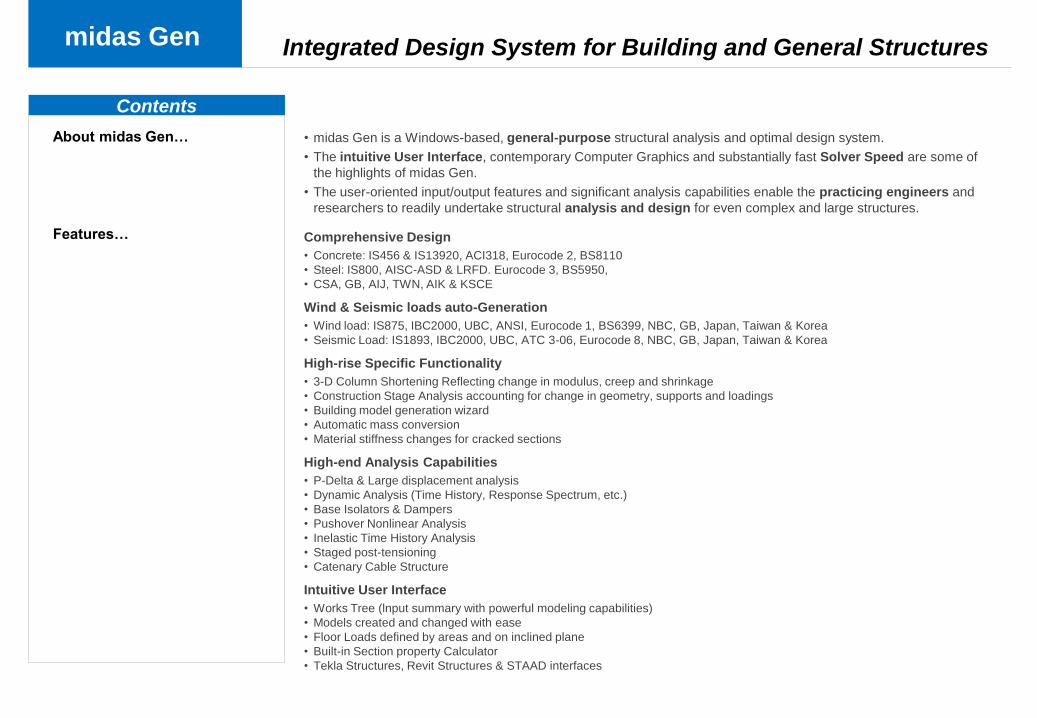
• midas Gen is a Windows-based, general-purpose structural analysis and optimal design system.
• The intuitive User Interface, contemporary Computer Graphics and substantially fast Solver Speed are some of
the highlights of midas Gen.
• The user-oriented input/output features and significant analysis capabilities enable the practicing engineers and
researchers to readily undertake structural analysis and design for even complex and large structures.
Comprehensive Design
• Concrete: IS456 & IS13920, ACI318, Eurocode 2, BS8110
• Steel: IS800, AISC-ASD & LRFD. Eurocode 3, BS5950,
• CSA, GB, AIJ, TWN, AIK & KSCE
Wind & Seismic loads auto-Generation
• Wind load: IS875, IBC2000, UBC, ANSI, Eurocode 1, BS6399, NBC, GB, Japan, Taiwan & Korea
• Seismic Load: IS1893, IBC2000, UBC, ATC 3-06, Eurocode 8, NBC, GB, Japan, Taiwan & Korea
High-rise Specific Functionality
• 3-D Column Shortening Reflecting change in modulus, creep and shrinkage
• Construction Stage Analysis accounting for change in geometry, supports and loadings
• Building model generation wizard
• Automatic mass conversion
• Material stiffness changes for cracked sections
High-end Analysis Capabilities
• P-Delta & Large displacement analysis
• Dynamic Analysis (Time History, Response Spectrum, etc.)
• Base Isolators & Dampers
• Pushover Nonlinear Analysis
• Inelastic Time History Analysis
• Staged post-tensioning
• Catenary Cable Structure
Intuitive User Interface
• Works Tree (lnput summary with powerful modeling capabilities)
• Models created and changed with ease
• Floor Loads defined by areas and on inclined plane
• Built-in Section property Calculator
• Tekla Structures, Revit Structures & STAAD interfaces
Contents
Integrated Design System for Building and General Structures
About midas Gen…
Features…
midas Gen
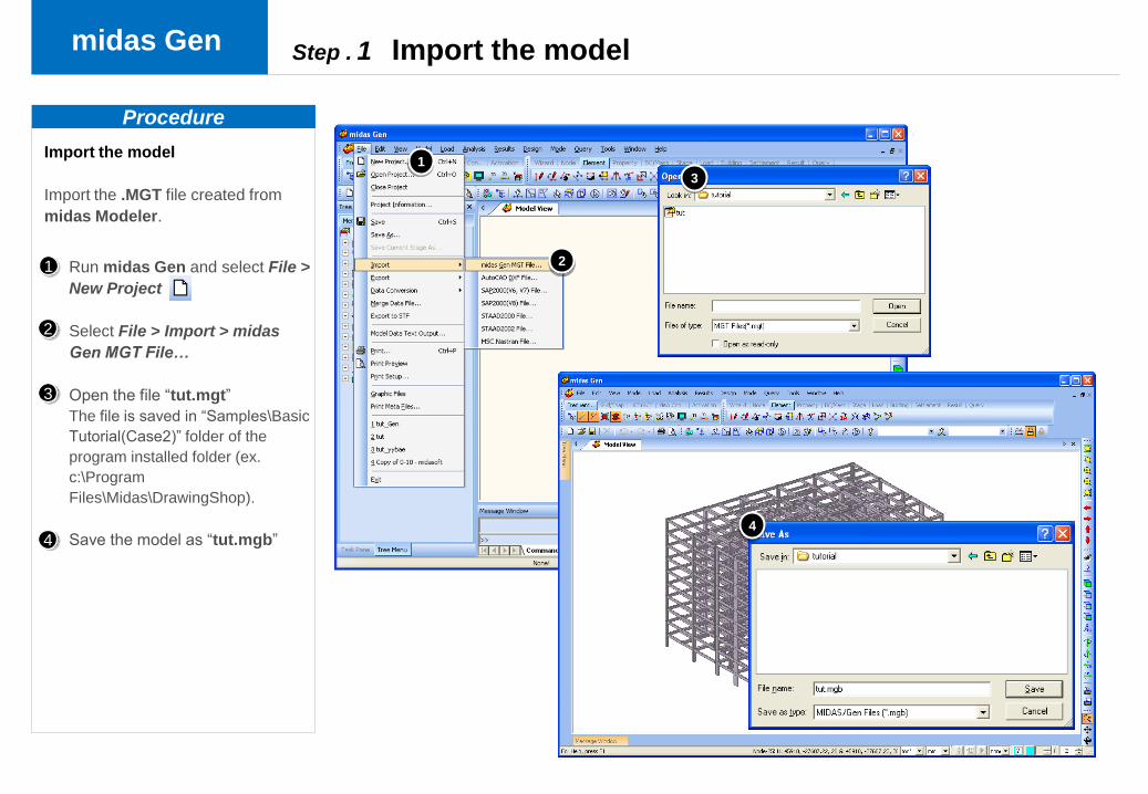
Import the model
Import the .MGT file created from
midas Modeler.
Procedure
Run midas Gen and select File >
New Project
Select File > Import > midas
Gen MGT File…
Open the file “tut.mgt”
The file is saved in “Samples\Basic
Tutorial(Case2)” folder of the
program installed folder (ex.
c:\Program
Files\Midas\DrawingShop).
Save the model as “tut.mgb”
Step . 1 Import the model
2
3
4
1
1
2
3
4
midas Gen
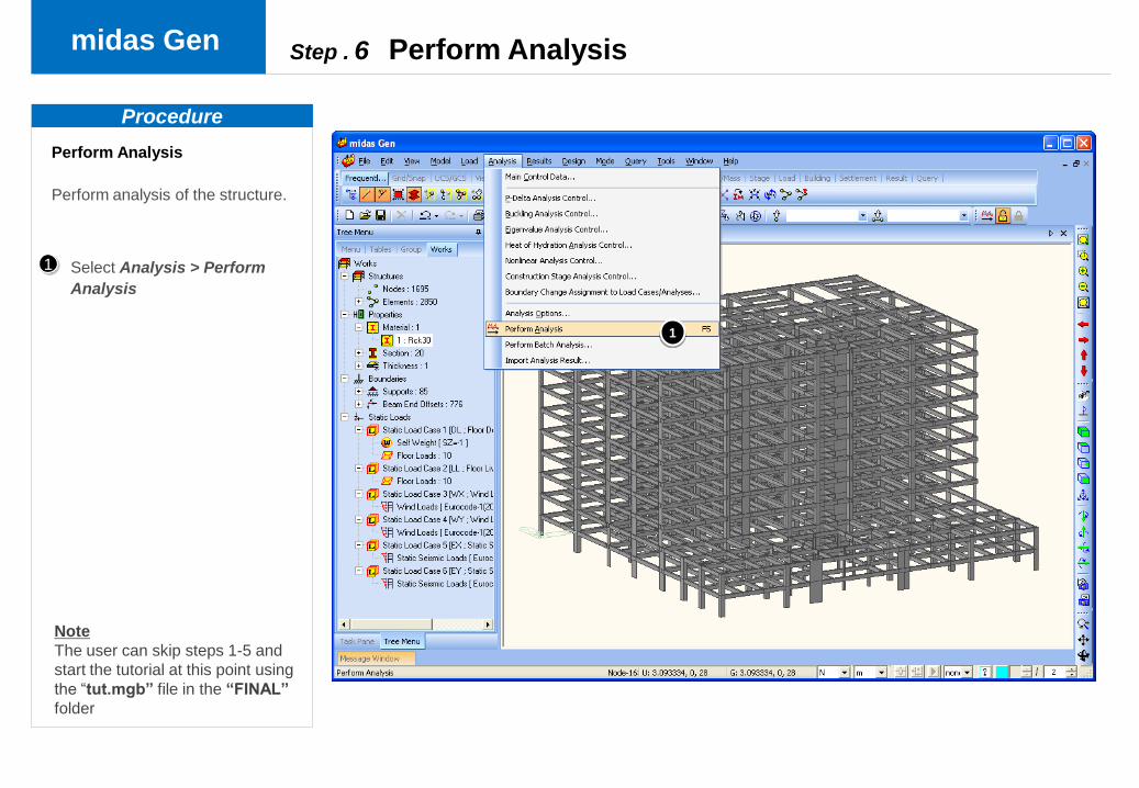
Perform Analysis
Perform analysis of the structure.
Select Analysis > Perform
Analysis
Step . 6 Perform Analysis
Procedure
1
1
Note
The user can skip steps 1-5 and
start the tutorial at this point using
the “tut.mgb” file in the “FINAL”
folder
midas Gen
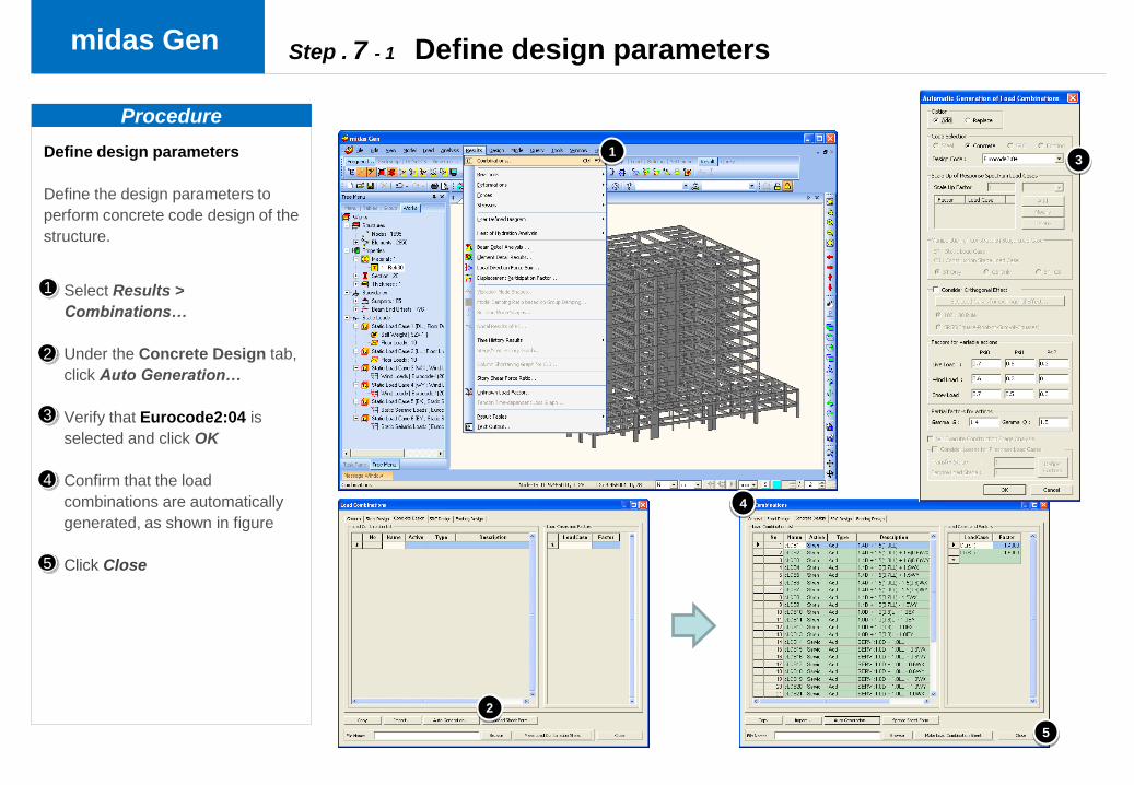
Define design parameters
Define the design parameters to
perform concrete code design of the
structure.
Select Results >
Combinations…
Under the Concrete Design tab,
click Auto Generation…
Verify that Eurocode2:04 is
selected and click OK
Confirm that the load
combinations are automatically
generated, as shown in figure
Click Close
Step . 7 - 1 Define design parameters
Procedure
2
3
4
1
5
1
2
4
3
5

midas Gen
Select Tools >Preferences… and
select the Design branch
Verify under Concrete that the
Design Code is Eurocode2:04,
Material Code is UNI(RC), and
the Material DB is FeB44k
2
1
Define design parameters
Define the design parameters to
perform concrete code design of the
structure.
Step . 7 - 2 Define design parameters
Procedure
1
2
midas Gen
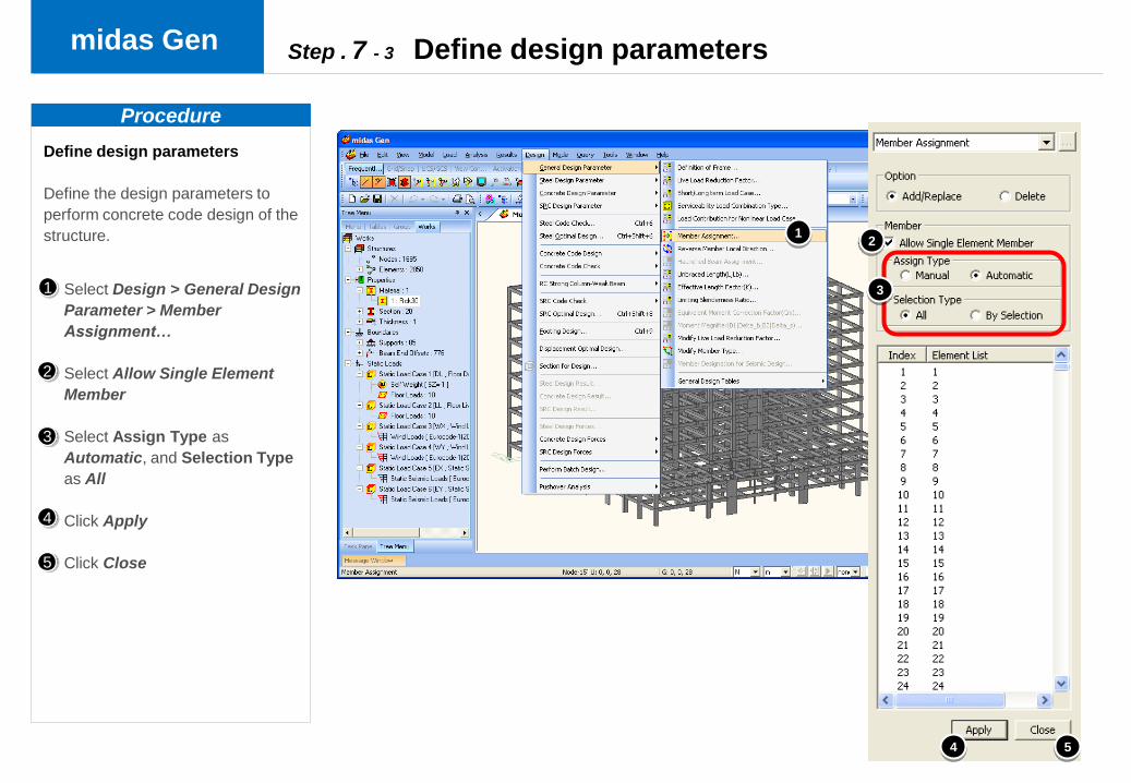
Select Design > General Design
Parameter > Member
Assignment…
Select Allow Single Element
Member
Select Assign Type as
Automatic, and Selection Type
as All
Click Apply
Click Close
Define design parameters
Define the design parameters to
perform concrete code design of the
structure.
Step . 7 - 3 Define design parameters
Procedure
2
3
4
5
1
12
4 5
3
midas Gen
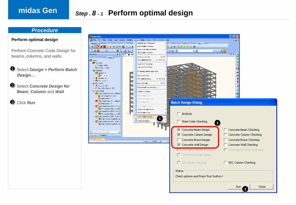
Perform optimal design
Perform Concrete Code Design for
beams, columns, and walls.
Select Design > Perform Batch
Design…
Select Concrete Design for
Beam, Column and Wall
Click Run
Procedure
2
1
Step . 8 - 1 Perform optimal design
1
2
3
3
midas Gen
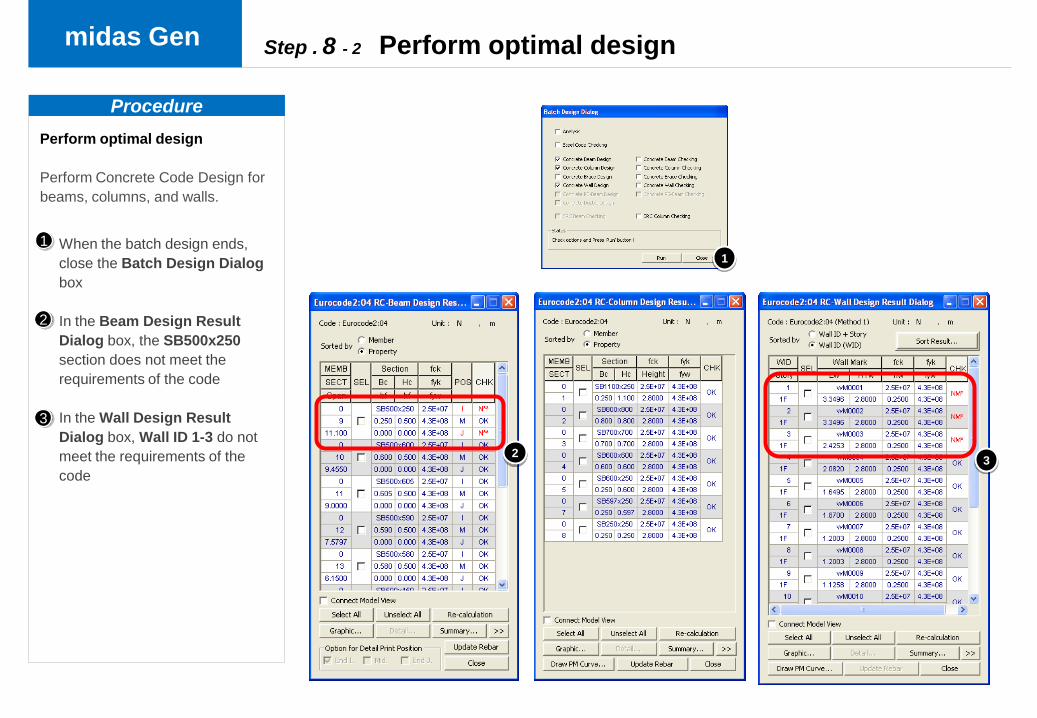
When the batch design ends,
close the Batch Design Dialog
box
In the Beam Design Result
Dialog box, the SB500x250
section does not meet the
requirements of the code
In the Wall Design Result
Dialog box, Wall ID 1-3 do not
meet the requirements of the
code
Perform optimal design
Perform Concrete Code Design for
beams, columns, and walls.
Procedure
Step . 8 - 2 Perform optimal design
2
11
2
3
3

midas Gen
Select Design > Concrete
Design Parameter > Design
Criteria for Rebars…
Click Rebar… on the right of
the Main Rebar field in the For
Beam Design section
Select P22 to P30, then click
OK
Procedure
2
3
1
Perform optimal design
Perform Concrete Code Design for
beams, columns, and walls.
Step . 8 - 3 Perform optimal design
1
3
2
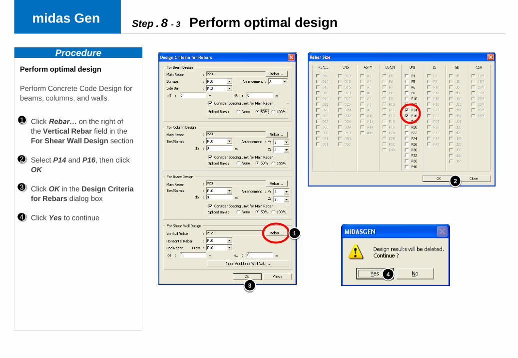
midas Gen
Click Rebar… on the right of
the Vertical Rebar field in the
For Shear Wall Design section
Select P14 and P16, then click
OK
Click OK in the Design Criteria
for Rebars dialog box
Click Yes to continue
Procedure
2
3
4
1
Perform optimal design
Perform Concrete Code Design for
beams, columns, and walls.
Step . 8 - 3 Perform optimal design
4
3
2
1

midas Gen
Procedure
Perform optimal design
Perform Concrete Code Design for
beams, columns, and walls.
Step . 8 - 4 Perform optimal design
Select Design > Perform Batch
Design…
Select Concrete Design for
Beam, Column and Wall. Click
Run
When the batch design ends,
close the Batch Design Dialog
box
Verify that the design meets
requirements of the code
Close all the results
2
3
1
4
5
5
44
5
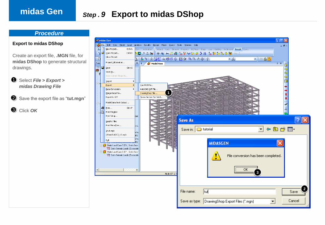
midas Gen
Export to midas DShop
Create an export file, .MGN file, for
midas DShop to generate structural
drawings.
Select File > Export >
midas Drawing File
Save the export file as “tut.mgn”
Click OK
Procedure
2
1
Step . 9 Export to midas DShop
1
2
3
3
Step
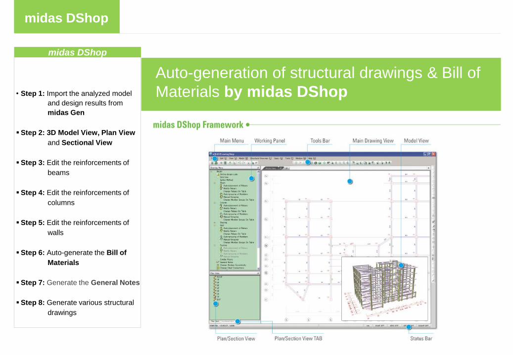
midas DShop
midas DShop
• Step 1: Import the analyzed model
and design results from
midas Gen
Step 2: 3D Model View, Plan View
and Sectional View
Step 3: Edit the reinforcements of
beams
Step 4: Edit the reinforcements of
columns
Step 5: Edit the reinforcements of
walls
Step 6: Auto-generate the Bill of
Materials
Step 7: Generate the General Notes
Step 8: Generate various structural
drawings
Auto-generation of structural drawings & Bill of
Materials by midas DShop

Step
midas DShop
About midas DShop …
midas DShop modules…
Introduction
Auto-drafting Module for midas Gen
midas DShop empowers engineers to streamline the design process all the way to generating
engineering drawings.
midas DShop imports models complete with analysis & design results from midas Gen and
automatically generates structural drawings.
midas DShop features the Drawing Generation Module & the Drawing Edit Module, which
enable engineers to analyze and modify design results to reflect their design intent.
midas DShop incorporates the advanced knowledge and engineering experience to generate
drawings of high quality.
midas DShop offers 3 main features:
-“Drawing Generation” for generating
various structural drawings,
-“Reinforcement Edit” for updating
reinforcement, and
-“Bill of Materials” to display material
quantity required for construction.
Drawing Generation Module
- Auto-placement of reinforcing bars reflecting constructability
- Convenient edit functions for RC reinforcement information
- Offset adjustment functions by Object bases
Drawing Edit Module
- Drawing environment and edit functions identical to AutoCAD
- Drawing functions for Members (Slab / Beam / Column / Brace / Wall / Foundation)
- Variety of symbol generation functions

Step
midas DShop
Run midas DShop and Select
File > New Project
Select File > Import > midas
Gen
Procedure
Step . 1 - 1 Import the analyzed model and design results from midas Gen
2
3
4
1
Click on the right of the File
Name field
Open the file “tut.mgn”
Import the analyzed model and
design results from midas Gen
The analyzed model and design
results from midas Gen can be
imported into midas DShop

Step
midas DShop
Procedure
Import the analyzed model and
design results from midas Gen
The analyzed model and design
results from midas Gen can be
imported into midas DShop
Verify the import preferences
as shown in the Import dialog
box
Click the Beam Rebar
Placement Method
Verify the rebar placement
method as shown in the
Rebar Placement Method
dialog box
Click OK for both dialog boxes
2
3
4
1
Step . 1 - 2 Import the analyzed model and design results from midas Gen
2
1
4
4
3

Step
midas DShop
Display of the 3D structural model
Double-click on the 5th story (5F)
in the Plan View panel
Display of the 5th story framing
plan
Select a beam member (1113) by
double-clicking
3D Model View, Plan View and
Sectional View
Verify the imported model and
design results using the Model
View, Plan View and Sectional
View
Procedure
Step . 2 - 1 3D Model View, Plan View and Sectional View
2
3
4
5
1
Verify the reinforcements in
the Modify Beam Rebars
dialog box, and click Close
Note
The user can start the tutorial at
this point using the “tut.mgd” file
in the “FINAL” folder
4
1
2
4
3
5

Step
midas DShop
Procedure
Verify the reinforcements in
the Modify Column Rebars
dialog box, and click Close
Click the Sectional View tab, then
double-click on the X1
Display of the Sectional Elevation
along the grid line X1
Select a column member (21) by
double-clicking
2
3
4
1
3D Model View, Plan View and
Sectional View
Verify the imported model and
design results using the Model
View, Plan View and Sectional
View
Step . 2 - 2 3D Model View, Plan View and Sectional View
1
2
3
3
4

Step
midas DShop
Procedure
Step . 3 -1 Edit reinforcements of Beams
Edit reinforcements of Beams
to reflect constructability
Edit the reinforcements of beams
to reflect constructability and user
requirements based on the design
results from midas Gen
Double-click on Model > Beam >
Auto-grouping of Members in
the Drawing Menu panel
Double-click on Model > Beam >
Change Rebars on Table in the
Drawing Menu panel
2
3
1
Click OK
Click 5F tab
4
Verify the assigned group name
of a member, as shown in the
figure
5
1
2
4
3
2
5
5
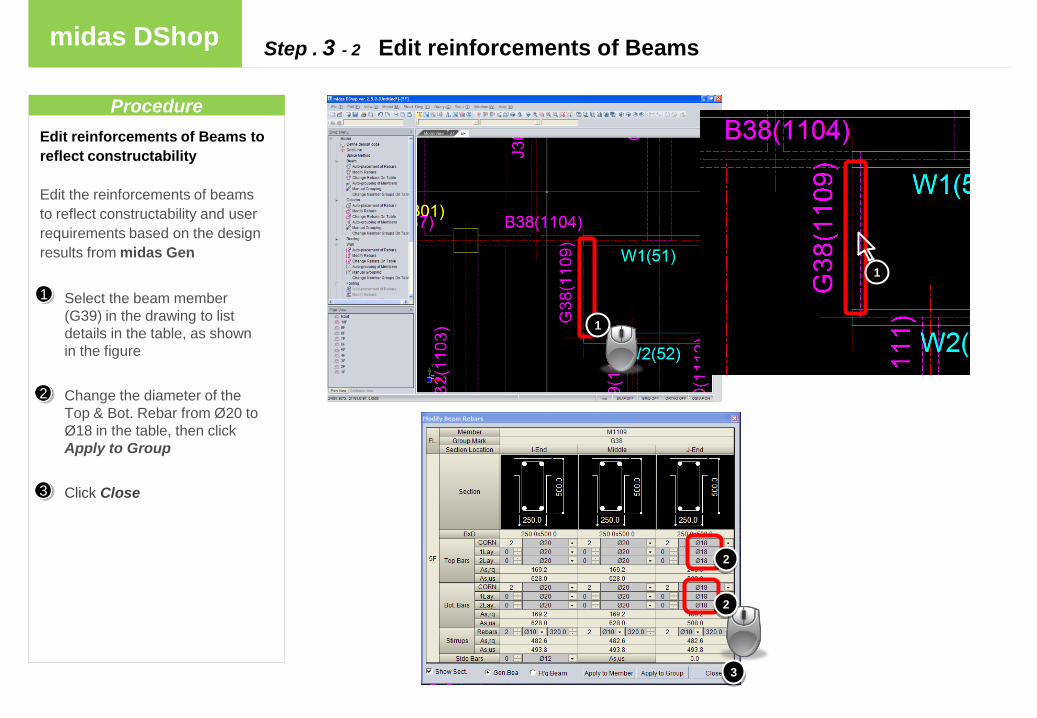
Step
midas DShop
Select the beam member
(G39) in the drawing to list
details in the table, as shown
in the figure
Change the diameter of the
Top & Bot. Rebar from Ø 20 to
Ø 18 in the table, then click
Apply to Group
Click Close
Procedure
Step . 3 - 2 Edit reinforcements of Beams
Edit reinforcements of Beams to
reflect constructability
Edit the reinforcements of beams
to reflect constructability and user
requirements based on the design
results from midas Gen
2
3
1
3
2
2
1
1

Step
midas DShop
Procedure
Step . 4 - 1 Edit reinforcements of columns
Edit reinforcements of columns
to reflect constructability
Edit the reinforcements of columns
to reflect constructability and user
requirements based on the design
results from midas Gen
Double-click on Model >
Column > Auto-grouping of
Members in the Drawing
Menu panel
Double-click on Model >
Column > Change Rebars on
Table in the Drawing Menu
panel
1
Click OK
2
3
Verify the assigned group name
of a member, as shown in the
figure
4
1
3
2
41
4

Step
midas DShop
Procedure
Step . 4 - 2 Edit reinforcements of columns
Edit reinforcements of columns
to reflect constructability
Edit the reinforcements of columns
to reflect constructability and user
requirements based on the design
results from midas Gen
Select the column member (C17)
in the drawing to list details in
the table, as shown in the figure
Change the diameter of the
Main Rebar from Ø 20 to Ø 22 in
the table, then click Apply to
Group
Click Close
2
3
1
1
3
2
2
1
Step
midas DShop
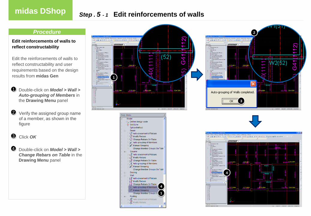
Edit reinforcements of walls to
reflect constructability
Edit the reinforcements of walls to
reflect constructability and user
requirements based on the design
results from midas Gen
Double-click on Model > Wall >
Auto-grouping of Members in
the Drawing Menu panel
Double-click on Model > Wall >
Change Rebars on Table in the
Drawing Menu panel
Procedure
Step . 5 - 1 Edit reinforcements of walls
Click OK
2
3
1
Verify the assigned group name
of a member, as shown in the
figure
4
1
3
2
1
4
4

Step
midas DShop
Select the wall member (W2) in
the drawing to list details in the
table, as shown in the figure
Change the space of the Main
Vert. Rebar from Ø 14 to Ø 12
and „300‟ to „200‟ in the table,
then click Apply to Group
Edit reinforcements of walls to
reflect constructability
Edit the reinforcements of walls to
reflect constructability and user
requirements based on the design
results from midas Gen
Procedure
Step . 5 - 2 Edit reinforcements of walls
2
3
1
1
Click Close
1
2
3
2
Step
midas DShop
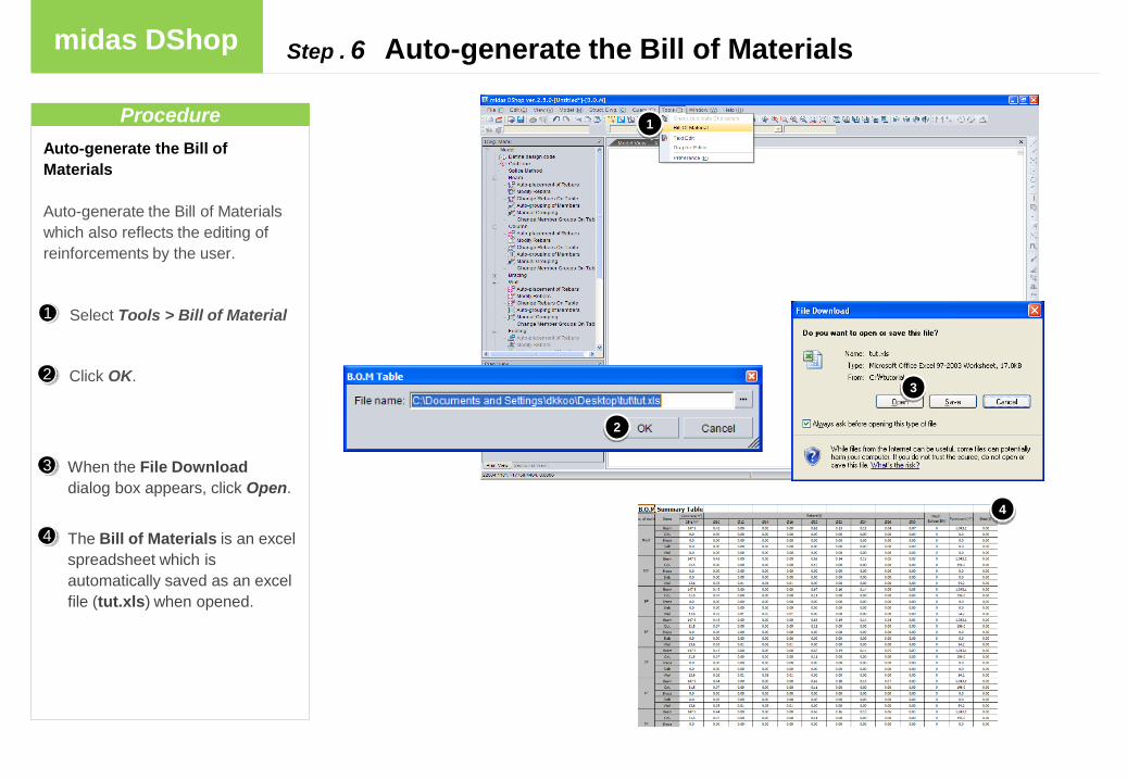
Select Tools > Bill of Material
Auto-generate the Bill of
Materials
Auto-generate the Bill of Materials
which also reflects the editing of
reinforcements by the user.
Procedure
Step . 6 Auto-generate the Bill of Materials
The Bill of Materials is an excel
spreadsheet which is
automatically saved as an excel
file (tut.xls) when opened.
Click OK.
When the File Download
dialog box appears, click Open.
2
3
1
4
3
4
1
2

Step
midas DShop
Select Struct. Dwg > Generate
Auto Drawings
Select the Setting tab
Select the drawing format as A1
and scales as Default
Select the Drawing Information
tab
Note
The outline, history and comments
of the drawing is defined in the
Drawing Information tab
Click OK
Procedure
Step . 7 - 1 Generate the General Notes
2
3
4
5
1
Generate structural drawing
outline
A midas CAD drawing format can
be generated and modified using
the Drawing Edit Module1
4
5
2
3

Step
midas DShop
Generate the General Notes
Procedure
Step . 7 - 2 Generate the General Notes
Select Tools > Preference
Select the view tab in the
Option dialog box
Change the Color from Black to
White, then Click OK
Double-click on Generate Auto
Dwg. in the Dwg. Panel
2
3
4
5
1
then Click OK
The Material of Structure,
Concrete, Rebars, etc., are
included in the General Notes
Note
When the Dwg. in midas CAD
format tab is selected, the
Drawing Edit Module is activated.
The user can change to the
Drawing Generation Module by
selecting the Model View, Plan
View, or Sectional View tabs.
Double-click on General Notes
and write a title. Choose the
location of the General Notes in
the drawing, then click to place
the General Notes
6
12
3
2
3
4
5
6 6

Step
midas DShop
Procedure
Step . 8 Generate various structural drawings
Select File > New Drawing
Select the Setting tab
Select the drawing format as A0
and scales as default
Select the Drawing Information
tab
Note
The outline, history and comments
of the drawing are defined in the
Drawing Information tab
Click OK
2
3
4
5
1
Generate new structural drawing
outline
The user can create new drawing
layouts, repeatedly
1
2
3
3
4
5
Step
midas DShop
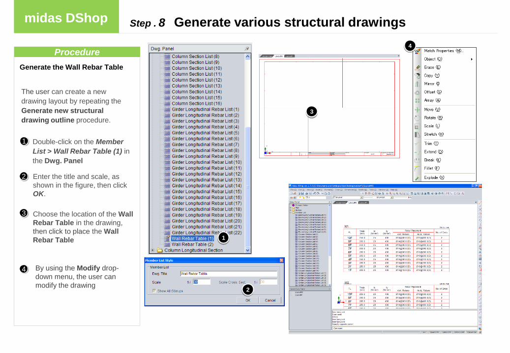
Generate the Wall Rebar Table
Double-click on the Member
List > Wall Rebar Table (1) in
the Dwg. Panel
Enter the title and scale, as
shown in the figure, then click
OK.
Choose the location of the Wall
Rebar Table in the drawing,
then click to place the Wall
Rebar Table
Procedure
2
3
1
Step . 8 Generate various structural drawings
The user can create a new
drawing layout by repeating the
Generate new structural
drawing outline procedure.
By using the Modify drop-
down menu, the user can
modify the drawing
4
1
4
1
2
3

Step
midas DShop
Generate the Girder Longitudinal
Rebar List
Procedure
Step . 8 Generate various structural drawings
Double-click on the Member
List > Girder Longitudinal
Rebar List (1) in the Dwg.
Panel
Enter the title and scale, as
shown in the figure, then click
OK.
Choose the location of the
Girder Longitudinal Rebar List
(1) in the drawing, then click to
place the Girder Longitudinal
Rebar List (1)
2
3
1
4
The user can create a new
drawing layout by repeating the
Generate new structural
drawing outline procedure.
By using the Modify drop-
down menu, the user can
modify the drawing
3
1
2
4

Step
midas DShop
Procedure
Step . 8 Generate various structural drawings
Double-click on the Member
List > Column Section List (1)
in the Dwg. Panel
Enter the title and scale, as
shown in the figure, then click
OK.
Choose the location of the
Column Section List (1) in the
drawing, then click to place the
Column Section List (1)
2
3
1
4
Generate the Column Section List
The user can create a new
drawing layout by repeating the
Generate new structural
drawing outline procedure.
By using the Modify drop-
down menu, the user can
modify the drawing
3
1
2
4

Step
midas DShop
Procedure
Step . 8 Generate various structural drawings
Double-click on the Section >
Line X1 Sectional Elev. in the
Dwg. Panel
Enter the title and scale, as
shown in the figure, then click
OK.
Choose the location of the Line
X1 Sectional Elevation in the
drawing, then click to place the
Line X1 Sectional Elevation
2
3
1
4
Generate the Line X1 Sectional
Elevation
The user can create a new
drawing layout by repeating the
Generate new structural
drawing outline procedure.
By using the Modify drop-
down menu, the user can
modify the drawing
3
1
2
4

Step
midas DShop
Procedure
Step . 8 Generate various structural drawings
Double-click on the Plan > 7F
Plan Drawing in the Dwg’s.
Panel
Enter the title and scale, as
shown in the figure, then click
OK.
Choose the location of the 7F
Plan Drawing in the drawing,
then click to place the 7F Plan
Drawing
2
3
1
4
Generate the 7F Plan Drawing
The user can create a new
drawing layout by repeating the
Generate new structural
drawing outline procedure.
By using the Modify drop-
down menu, the user can
modify the drawing
3
1
2
4