introduction and contractors in the design and ... standard specs.pdf · ......
TRANSCRIPT

H:\Projects\GG_Standards\Revision_2014\Introduction 2014.doc
INTRODUCTION
These Standard Specifications are to be used as a guide by Private Engineers and Contractors in the design and installation of all additions or modifications to the City of Garden Grove's Public Water System. It is the intent that these Standard Specifications will provide uniformity in materials and installation of piping, valves, fire hydrants, service laterals and other appurtenant equipment. The Standard Specifications will also provide for construction methods and controls to be used by Contractors to construct, pressure test, chlorinate and place into service domestic water systems in the City of Garden Grove.

iii H:\Projects\GG_Standards\Revision_2014\Introduction 2014.doc
CITY OF GARDEN GROVE PUBLIC WORKS DEPARTMENT WATER SERVICES DIVISION STANDARD SPECIFICATIONS TABLE OF CONTENTS
SECTION 1 GENERAL PROVISIONS 1-01 Plans and Specifications 1-02 Definitions 1-03 Abbreviations
SECTION 2 MATERIALS 2-00 General 2-01 Ductile Iron Pipe 2-02 Polyvinyl Chloride Pipe 2-03 Copper Tubing 2-04 Red Brass Pipe 2-05 Main Line Valves 2-06 Air and Vacuum, Air Release and Combination Air Valves
2-07 Fire Hydrants 2-08 Main Line Pipe Fittings 2-09 Main Line Couplings 2-10 Service Lateral Installation 2-11 Small Meters 2-12 Thrust Restraining Materials 2-13 Shop Drawing and Material Submittals 2-14 Painting – Above Ground Installations 2-15 Access to Manufacturing and Test Facilities
SECTION 3 CONSTRUCTION METHODS AND CONTROL
3-01 Inspection 3-02 Pre-Construction Details 3-03 Removals and Trench Excavation 3-04 Connection to Existing Facilities 3-05 Laying of Ductile Iron Pipe Water Main
3-06 Laying of PVC Pipe Water Main 3-07 Repair, Removal and Disposal of Asbestos Cement Pipe
3-08 Service Laterals 3-09 Pipe Bedding and Backfilling of Trench 3-10 Repaving and Finishing 3-11 Testing, Disinfection, and Flushing

iv H:\Projects\GG_Standards\Revision_2014\Introduction 2014.doc
3-12 Special Conditions 3-13 Dedication of Improvements to the City 3-14 As – Built Drawings
SECTION 4 LARGE SERVICES AND FIRE LINES
4-01 General 4-02 Design 4-03 Fees 4-04 Construction and Inspection 4-05 Easements 4-06 Meters 4-07 Vault Installations 4-08 Thrust Restraint - Vault Installation 4-09 Painting - Above Ground Installations 4-10 Aesthetics - Above Ground Installations
SECTION 5 BACKFLOW PREVENTION 5-01 Backflow Protection
5-02 Fire Line Assembly
LIST OF STANDARD PLANS B - 701 WET BARREL FIRE HYDRANT - COMMERCIAL/INDUSTRIAL
B - 702 WET BARREL FIRE HYDRANT - RESIDENTIAL B - 703 GUARD POST DETAIL FOR FIRE HYDRANTS
B - 704 CONCRETE COLLAR DETAIL B - 705 FIRE HYDRANT SETBACK DETAIL
B - 710 ANCHOR BLOCK DETAILS FOR 4 THRU 12 INCH D.I. FITTINGS B - 711 ANCHOR BLOCK DETAIL FOR 45-DEGREE VERTICAL BEND B - 712 ANCHOR BLOCK DETAIL FOR PVC WATER MAIN VALVES B - 713 ANCHOR BLOCK DETAILS FOR 6” THRU 16” PIPES B - 714 REVERSE TIE ANCHOR BLOCK ASSEMBLY FOR 6” THRU 16” PIPE B – 718 METER BOX INSTALLATION WITH NEW CONCRETE REPLACEMENT B - 719 1” COPPER WATER SERVICE FOR RESIDENTIAL FIRE SERVICE B - 720 1” COPPER WATER SERVICE SAMPLE CONNECTION B - 721 1" COPPER WATER SERVICE INSTALLATION FOR 5/8” & 1” METERS B - 722 1-1/2” x 2” OMNI R2-C2 METERS AND 2” COPPER WATER SERVICE
INSTALLATION B - 723 1-1/2” x 2” TURBO METER AND 2” COPPER WATER SERVICE
INSTALLATION B - 724 3”, 4” AND 6” COMPOUND METER AND SERVICE INSTALLATION B - 725 3”, 4” AND 6” TURBO METER AND SERVICE INSTALLATION B - 729 SERVICE LATERAL INSTALLATION FOR PRIVATE FIRE HYDRANTS B - 730 2-1/2” TEMPORARY WATER SERVICE
v H:\Projects\GG_Standards\Revision_2014\Introduction 2014.doc
B - 739 2” Tap to 1” AIR AND VACCUM RELIEF VALVE ASSEMBLY B - 740 1” AIR AND VACUUM RELIEF VALVE ASSEMBLY B - 741 2” AIR AND VACUUM RELIEF VALVE ASSEMBLY B - 742 AIR RELEASE AND VACUUM RELIEF ENCLOSURE ASSEMBLY B - 743 AIR RELEASE & VACUUM RELIEF ENCLOSURE SETBACK DETAIL B - 744 2” BLOWOFF INSTALLATION AT END OF 4” WATER MAIN PIPE B - 745 4" BLOWOFF INSTALLATION FOR 6” OR LARGER MAINS B - 746 SAMPE POINT FOR NEW WATER MAIN B - 749 CUT – IN VALVE B - 750 TAPPING SLEEVE AND GATE VALVE B - 751 WELDED TAPPING NOZZLE AND GATE VALVE FOR STEEL CYLINDER
PIPE B - 752 GATE VALVE CAN ASSEMBLY B - 753 GATE VALVE CAN ASSEMBLY FOR CONCRETE AREAS B - 754 OLD GATE VALVE CAN ASSEMBLY REPLACEMENT B - 760 SEPARATION REQUIREMENTS FOR NEW WATER MAIN AND EXISTING
SEWER MAIN B - 761 SEPARATION REQUIREMENTS FOR NEW SEWER MAIN AND EXISTING
WATER MAIN B - 762 SEWER MAIN CROSSING UNDER WATER MAIN
B - 763 WATER MAIN CROSSING UNDER SEWER MAIN B - 764 INSTALLATION OF WATER PIPE THROUGH STEEL CASING
B - 765 DUCTIL IRON VERTICAL OFFSET B - 766 DUCTIL IRON HORIZONTAL OFFSET
B - 767 WELDED STEEL OFFSET B - 769 ABOVE GROUND FIRE LINE AND BACKFLOW DEVICE SCREENING AND
SETBACK REQUIREMENTS B - 770 TYPICAL 2” OR SMALLER REDUCED PRESSURE PRINCIPLE DEVICE
(RPPD) B - 771 TYPICAL 2-1/2” OR LARGER REDUCED PRESSURE PRINCIPLE DEVICE
(RPPD) B - 773 TYPICAL 2-1/2” OR LARGER DOUBLE CHECK DETECTOR CHECK FIRE
LINE ONLY B - 774 BACKFLOW CAGE FOR TYPICAL 2” OR SMALLER REDUCED PRESSURE PRINCIPAL DEVICE (RPPD) B – 781 WARNING IDENTIFICATION TAPE AND TRACER WIRE INSTALLATION
1-1
SECTION 1 - GENERAL PROVISIONS 1-01 PLANS AND SPECIFICATIONS
Construction of all water system improvements intended to be dedicated to the City will be governed by plans and specifications approved by the Water Services Division. All plans and specifications must be prepared by, or under the supervision of a current registered engineer licensed to practice in the state of California. All work shall be subject to fees as provided for in the City's Water Rates, Rules and Regulations and shall be inspected by the Water Services Division to ensure conformity to these specifications.
In cases of conflict of information, the following documents will have precedence in the order listed:
1. Permits and licenses from affected agencies issued for the improvements.
2. Special provisions for the improvements.
3. Construction plans for the improvements.
4. City of Garden Grove Public Works Department Water Services Division Standard
Specifications (WSDSS).
5. Standard Specifications for Public Works Construction (SSPWC), “Green Book”. 6. Manufacturer’s recommendations of product use and installation.
Conflicts and discrepancies noted by the Contractor shall be brought to the attention of the Director, Public Works Department, or designated representative. The Director, Public Works Department, or designated representative will review the conflicts or discrepancies and determine the appropriate course of action to follow, if any. Unless otherwise determined by the Engineer, the most stringent/restricted condition shall govern over all. Contractor/Developer shall check with zoning code and/or local ordinances for special requirements and color schemes on all above ground facilities.
Provisions of reference specifications noted in these specifications and plans shall have the same effect as if written herein, unless expressly modified by these specifications. Any reference specification in the absence of designation to the contrary, shall be understood to refer to the latest revision at the time of the beginning of work.
SECTION 1 - GENERAL PROVISIONS
1-2 G:\GG-ENGG\data\acaddata\New-GG-STD\2013 Standard Plans\Standard Specs\2015 Water Specs\1 Section 2014.doc
1-02 DEFINITIONS
Whenever the following terms or corresponding pronouns are used in these specifications or plans, the intent and meaning shall be interpreted as follows:
a. City The City of Garden Grove, California.
b. Engineer: The Project Engineer or his authorized representative.
c. Water Services Division The Director, Public Works Department, Water Services
Division, City of Garden Grove or designated representative.
d. Planning Services Division The Director, Community Development Department,
Planning Services Division, City of Garden Grove or designated representative.
e. Fire Department The Chief, Fire Department, City of Garden Grove or
designated representative. f. Developer: The person or organization having legal responsibility for
construction of water systems in conjunction with development of property.
g. Contractor: The agent of the developer or independent contractor who
furnishes labor, material, equipment, method, etc. to perform the requirements of these specifications in the construction of water systems.
h. Superintendent: The field representative of the Contractor, present on the
job site at all times during work, who is authorized to receive and fulfill instructions from the City.
i. Private Engineer: The agent of the developer, City of Garden Grove, or
independent engineer who has responsibility for the design and drawing of construction documents.
j. Or approved equal: An equivalent product to that specified in these standard
specifications, approved by the Water Services Division before beginning of construction. No approved equal product is intended, unless so stated in these standard specifications.
SECTION 1 - GENERAL PROVISIONS
1-3 G:\GG-ENGG\data\acaddata\New-GG-STD\2013 Standard Plans\Standard Specs\2015 Water Specs\1 Section 2014.doc
k. Drawings: The words “DRAWINGS” or “CONTRACT DRAWINGS” or “PLANS” shall mean those drawings accompanying the specifications which show the location, nature, extent and form of the work, together with applicable details.
1-03 ABBREVIATIONS
Whenever the following abbreviations are used in these specifications, the meaning shall be interpreted as follows: ASTM: American Society for Testing and Materials AWWA: American Water Works Association ANSI: American National Standards Institute UNI-BELL Uni-Bell PVC Pipe Association DIPRA: Ductile Iron Pipe Research Association CAL-OSHA: California Occupational Safety and Health Administration SSPC: The Society of Protective Coatings SSPWC: Standard Specifications for Public Works Construction.
(Green Book)- Latest Edition CBC: California Building Code, 2013 Edition CFC: California Fire Code, 2013 Edition UPC: Uniform Plumbing Code WSDSS: Water Services Division Standard Specifications (Garden
Grove Public Works Department) NSF: National Sanitation Foundation

SECTION 2 - MATERIALS
2-1 G:\GG-ENGG\data\acaddata\New-GG-STD\2013 Standard Plans\Standard Specs\2015 Water Specs\2 Section 2014_rv03.doc
SECTION 2 - MATERIALS
2-00 GENERAL
All materials and equipment installed in City of Garden Grove’s water system shall meet all state and federal standards, as well as standards developed by nationally recognized organizations such as AWWA, ANSI and NSF. In order to protect human health, all materials, chemicals, lubricants, and products in contact with drinking water shall be tested and certified as meeting ANSI/NSF 60-2001/ Addendum 1.0-2001 (Drinking Water Treatment Chemicals- Health Effects) and ANSI/NSF Standard 61-2001/Addendum 1.0-2001 (Drinking Water System Components- Health Effects).
2-01 DUCTILE IRON PIPE
2-01.01 GENERAL
Ductile iron pipe (DIP) shall conform to the requirements of the AWWA Standard C151. Unless otherwise specified, DIP shall only be used for pipe larger than twelve-inch (12) and shall be Special Thickness Class 51.
2-01.02 PIPE JOINTS
Ductile iron pipe shall be furnished in eighteen-foot (18) or twenty-foot (20’) nominal laying lengths and shall have a push-on joint employing a single rubber gasket in accordance with AWWA Standard C111, (“TYTON” Joint as manufactured by U.S. Pipe, or approved equal).
Where restrained joints are indicated on the Drawings, push-on joints shall be restrained in accordance with the requirements of Section 2-12.02.
2-01.03 COATING AND LINING
All pipe shall have the interior cement-mortar lined with a seal coat in accordance with AWWA Standard C104, and the outside coated with a bituminous material as specified in AWWA Standard C151.

SECTION 2 - MATERIALS
2-2 G:\GG-ENGG\data\acaddata\New-GG-STD\2013 Standard Plans\Standard Specs\2015 Water Specs\2 Section 2014_rv03.doc
2-01.04 POLYETHYLENE PROTECTIVE WRAPPING
Polyethylene protective wrapping (“Polywrap”) shall conform to the requirements of ANSI/AWWA C105/A21.5 and be eight (8) mil thick tubing of virgin polyethylene (Dupont Alathon, U.S. 1. Petrothene resin, or approved equal) or four (4) mil thick high-density, cross-laminated (HDCL) polyethylene. The color shall be (a) natural (where exposure to sunlight will be less than 48 hours); or (b) black, containing 2.0 to 2.5% well dispersed carbon black with stabilizers (where exposure to sunlight may be up to 10 days). Tubing shall be taped and secured with general purpose polyethylene tape, 2 inches wide and 10 mils thick (Scotchrap No. 50, Plicoflex No. 340, Protecto Wrap No. 200, Polyken No. 900, or approved equal).
2-02 POLYVINYL CHLORIDE PIPE
2-02.01 GENERAL
Polyvinyl chloride (PVC) pipe shall conform to the requirements of the AWWA Standard C 900, DR 14, (PC. 305), and molecularly oriented polyvinyl chloride (PVCO) pipe shall conform to the requirements of the AWWA Standard C 909, (PC 305). Unless otherwise specified, PVC or PVCO shall only be used for pipe sizes, 4 inch through 12 inch. PVC or PVCO Pipe for pipes larger than twelve-inch (12") require special approval from Engineering Services. All PVC Pipe shall and all PVCO pipe shall be colored blue. A number 14-gauge, solid, soft drawn insulated copper tracer wire is required per Standard Drawing B-781 on all PVC and PVCO installations.
2-02.02 PIPE JOINTS
PVC or PVCO pipe shall be furnished in twenty-foot (20’) nominal laying lengths and have bell-end push-on joints employing a single elastomeric gasket in accordance with AWWA Standard C900, C905, and/or C909.
2-02.03 PIPE SERVICES AND APPURTENANCES
All service saddles, sleeves, fittings, restraining devices, and other appurtenances used on PVC and PVCO Pipes shall be approved by the Water Services Division prior to use.
2-02.04 RESTRAINED JOINT PVC PIPE
Restrained joint non-metalic couplings for Poly-Vinyl Chloride (PVC) or Molecularly Oriented Poly-Vinyl Chloride (PVCO) pipe shall be CERTALOKTM
C900 RJ system, as manufactured by CertainTeed Corporation, or approval
SECTION 2 - MATERIALS
2-3 G:\GG-ENGG\data\acaddata\New-GG-STD\2013 Standard Plans\Standard Specs\2015 Water Specs\2 Section 2014_rv03.doc
equal.
See sections 2-12 for additional thrust restraint systems for PVC and PVCO pipes.
2-02.05 INSTALLATION CURVATURE
Where the pipeline is a non-restrained joint and to be installed in a curved alignment, the radius of curvature and specific alignment shall be as shown on the plans and shall be accomplished by means of deflecting the pipeline at the joints with couplings. Couplings in any of the curved alignment for this project where required deflection is between 1 and 5 degrees shall be High Deflection Couplings, Class 200 manufactured by CertainTeed or approved equal.
Contractor shall not exceed the manufacturer’s recommendation for deflection for the couplings. Bending of the PVC and PVCO is not allowed. The cost of providing pipe material and specialized tools to achieve the required curvature shall be included in the unit cost for the pipeline and no additional compensation will be allowed.
2-02.06 MARKINGS
Pipe shall be legible and permanently marked in ink with the following information.
Manufacturer and Trade Name Nominal Size and DR Rating/Pressure Class Hydrostatic Proof Test Pressure [NSF-61] Manufacturing Date Code
2-02.07 WORKMANSHIP The beveled end of any PVC or PVCO pipe shall be cut off before the pipe is
inserted into a mechanical joint fitting. 2-02.08 FITTINGS FOR PVC MAIN LINE
Main line PVC or PVCO pipe fittings shall be as called for on the construction plans. All fittings shall be ductile iron fittings per Section 2-08.

SECTION 2 - MATERIALS
2-4 G:\GG-ENGG\data\acaddata\New-GG-STD\2013 Standard Plans\Standard Specs\2015 Water Specs\2 Section 2014_rv03.doc
2-03 COPPER TUBING
2-03.01 GENERAL
This specification shall cover the requirements for 1-inch and 2-inch seamless, annealed, Type “K”, copper water tube. Copper tubing shall meet the requirements of ASTM B-88, “Specifications for Seamless Copper Water Tube”. The 2-inch copper water tube shall be of the rigid type.
2-03.02 DIMENSIONS
Copper tubing shall be furnished in coils or straight lengths, as follows:
SIZE FORM LENGTH
1" Coils 60 to 100' 2" Straight Lengths (rigid) 20'
Coils shall be wound in a single layer flat with a minimum 24-inch inside diameter.
2-03.03 TEMPER
Copper tubing shall be furnished in the annealed condition in accordance with the technical property requirements of ASTM B-88. Straight lengths shall be annealed after being drawn.
2-04 RED BRASS PIPE
Brass pipe shall conform to the requirements of the “Specifications for Seamless Red Brass Pipe, Standard Sizes” ASTM Specification B-43 and referenced in the appendix to AWWA Standard C800. Fittings shall be of bronze conforming to the requirements of ASTM B-62, “Specifications for Composition Bronze or Ounce Metal Castings”.
2-05 MAIN LINE VALVES
2-05.01 GENERAL
Valves shall be iron-body fusion bonded epoxy lined, non-rising stem, butterfly or fully encapsulated resilient wedge disk type and shall not have more than two internal moving parts. All valves shall open by turning the wrench nut counter-clockwise. Operating nut for butterfly valves shall be placed at the north or east

SECTION 2 - MATERIALS
2-5 G:\GG-ENGG\data\acaddata\New-GG-STD\2013 Standard Plans\Standard Specs\2015 Water Specs\2 Section 2014_rv03.doc
side of the water line.
When required, above ground installations shall be resilient seat/wedge disk type valves with outside screw and yoke.
All bronze parts shall contain not more than 7% zinc, nor more than 2% aluminum. Stems shall be low zinc bronze, and equipped with a 2-inch operating nut conforming to AWWA C509. The valve manufacturer shall employ a positive physical means of indicating the specified stem material to insure ready recognition during inspection.
The bolts and nuts on the bonnet shall be stainless steel type 304 or 316 with an anti-seize lubricant.
The ductile iron interior and exterior of all valves shall be protected with 10 mils (nominal) fusion bonded epoxy. Coating shall conform to AWWA Standard C-213 and C550, and shall be certified to NSF 61. For above ground or vault installation, exterior coating to valves shall be as per Section 2-14 for coating on above ground or vault installation. Resilient wedge type valves with a flanged end may be used as “tapping valves”. All valves shall be provided with a stem extension if depth of valve nut exceeds 4 feet. All valve extensions shall be centered in the valve well by use of a guide and shall operate freely without binding after installation.
2-05.02 GATE VALVES
Gate valves shall conform to the requirements of AWWA Standard C509 “Resilient-Seated Gate Valves for Water Supply Service” with fully encapsulated disk and guide lugs and as supplemented herein.
All gate valves shall be full wall ductile iron body, resilient wedge gate valves equipped with double O-ring stem seals. If the resilient seats are bonded to the gates, the gates shall be totally encapsulated with the material, with the exception of any guide tabs or slots. All valves shall have non-rising stems. The design of the non-rising stems shall be such that if excessive input torque is applied, stem failure shall occur above the stuffing box at such a point as to enable the operation of the valve with a pipe wrench or other readily available tool. Valves shall be suitable for frequent operation as well as service involving long period of inactivity, and capable of operating satisfactorily with flows in either

SECTION 2 - MATERIALS
2-6 G:\GG-ENGG\data\acaddata\New-GG-STD\2013 Standard Plans\Standard Specs\2015 Water Specs\2 Section 2014_rv03.doc
direction. Guide caps of an Acetal bearing material shall be placed over solid guild lugs to prevent abrasion and to reduce the operating torque. All exterior fasteners, including all bonnet and seal plate bolts and nuts shall be 300 series 18-8 stainless steel or approved equal corrosion resistant material. Valve stem seals shall be O-rings in conformance with AWWA C509 and shall be designed so that the O-ring above the stem collar can be replaced while the valve is under pressure and in the fully open or fully closed position. Valves shall be supplied with stems having a minimum yield strength of 38,000 psi and a minimum elongation in 2 inches of 12%. Valve stem, stem nuts and stem collar shall be made of low zinc bronze or approved equal material. Valves 3” and 4” in diameter shall be designed for an input torque of 300 foot pounds at the fully opened or fully closed positions, without any distortion of any kind to the valve or its components. Valves 6” through 12” in diameter shall be designed for an input torque of 450 foot pounds at the fully opened or fully closed positions, without any distortion of any kind to the valve or its components. Each valve shall be tested in accordance with AWWA C509 and certified to NSF 61 after shop assembly.
2-05.03 APPROVED GATE VALVE MANUFACTURERS
Mueller A-2362 US PIPE Or approved equal
2-05.04 BUTTERFLY VALVES
Butterfly valves shall conform to the requirements of AWWA Standard C504. Valves shall have a minimum working differential pressure across the valve disc of a 150-psi for class 150B valves and 250 psi for class 250B valves. Valves shall be flanged short-body or restrained mechanical joint as indicated per the Construction Drawings. Flanges shall be drilled per ANSI/B16.1, 125-pound standard bolt template. Valves shall be designed for buried installation.

SECTION 2 - MATERIALS
2-7 G:\GG-ENGG\data\acaddata\New-GG-STD\2013 Standard Plans\Standard Specs\2015 Water Specs\2 Section 2014_rv03.doc
Component Material Specification
Body Ductile Iron ASTM A-536, Grade 65-45-12 Valve Shaft Stainless Steel Type 304 or Type 316 Exposed body, cap screws, bolts and nuts including squeeze-pins
Stainless Steel ASTM A-276, Type 316
Disc Cast Iron or Ductile Iron
ASTM A-48, Class 40 or ASTM A-536, Grade 65-45-12
Valve Seat EPDM rubber ASTM D-412 O-Rings Synthetic Rubber ASTM D-2000
Valve seat material shall be peroxide cured EPDM rubber seat and shall be fastened integrally with the valve body. The valve disc shall be furnished with a stainless steel seating edge to mate with the rubber seat in the valve body. Valves with the seat located on the disc shall not be accepted. The ductile iron interior shall be shop coated with NSF 61 approved fusion bonded epoxy or coated with NSF 61 approved 12 mils DFT high solids 2 part epoxy of not less than 65% conforming to AWWA standard C550. Interior shall be holiday free. External surfaces shall be shop coated with two coats of asphalt varnish per Federal Specification TT-C-494A. Valve operators shall be the manual type. All valves and actuators shall be supplied by the valve manufacturer. Gear actuators shall be for buried service applications and shall come furnished with a standard 2” AWWA operating nut. The operators shall be of a worm gear or traveling nut type with adjustable stops to limit the disc travel and shall be totally enclosed and self locking. The actuator shall be capable of withstanding 300 ft-lb (worm gear) and 450 ft-lb (travel nut gear) at the stops. The actuator shall be sized for bi-directional maximum pressures and flow rate per AWWA valve classification 150B (250B when specified). All external bolts on the actuator shall be furnished with 316 stainless steel. The operator shall be of the size required for opening and closing the valve in accordance with AWWA C-504. All valve operators shall be factory packed with grease, fully gasketed and sealed for permanent installation and operation. Factory signed and dated affidavit of compliance shall accompany all submittals. Affidavits shall include “holiday free” paint, actuator stops compliance of 450 foot pounds, proof of design per AWWA C504 latest version for valves and actuator, and bi-directional seat leak test. Signatures of agents or distributors of the factory will not be accepted.
SECTION 2 - MATERIALS
2-8 G:\GG-ENGG\data\acaddata\New-GG-STD\2013 Standard Plans\Standard Specs\2015 Water Specs\2 Section 2014_rv03.doc
2-05.05 APPROVED BUTTERFLY VALVE MANUFACTURERS
Mueller B-3211 (Lineseal XP) Pratt Ground hog
DeZurik BAW 2-05.06 END CONNECTIONS & GASKET MATERIAL
Valves shall have mechanical joints or flanged ends, or a combination of both. Gaskets shall conform to the requirements of Section 2-08.03 of these specifications.
Unless otherwise shown on plans, all valves installed at fittings shall be flanged by mechanical ends, with the flange abutting the fitting.
2-05.07 VALVE BOXES & CAN ASSEMBLY
Valve boxes and can assembly shall be provided per Standard Drawings B-752 and B-753.
2-06 AIR AND VACUUM, AIR RELEASE, AND COMBINATION AIR VALVES
Air and Vacuum, Air Release and Combination Air Valves shall conform to AWWA C512 and be designed for a working pressure of 150 psi, unless otherwise specified. Float, linkage and all internal parts shall be 8-18 stainless steel. Interior coating for cast iron body shall be NSF 61 approved fusion bonded epoxy. Valves shall be APCO as manufactured by Valve and Primer Corporation, Crispin by Multiplex Manufacturing Co., Cla-Val, or approved equal.
APCO CRISPIN CLA-VAL BERMAD Air/Vacuum Series 140 Series AL Series 35 1/2"-ARV Air Release 50/200A Series AR/PL Series 34 2"-ARK, 1"-ARA Combination Air Series 140C Series UL Series 36 2"-ARC
SECTION 2 - MATERIALS
2-9 G:\GG-ENGG\data\acaddata\New-GG-STD\2013 Standard Plans\Standard Specs\2015 Water Specs\2 Section 2014_rv03.doc
2-07 FIRE HYDRANTS
2-07.01 GENERAL
Fire hydrants shall be of the wet-barrel type, conforming to AWWA C503, and as supplemented herein. The Engineer may require a break-off check valve with the wet-barrel type due to location, terrain, available drainage area, and/or system pressure.
2-07.02 MATERIALS AND PARTS
Fire hydrants shall have two 2 1/2-inch hose outlets and one 4-inch pumper outlet, or have one 2 1/2-inch hose outlet and two 4-inch pumper outlets. Outlet threads shall conform to ANSI-B26 “National Standard Fire-Hose Coupling Screw Threads”.
Fire hydrants shall be furnished with a pentagon shaped operating nut 1-1/2 inch per side, and opening shall be counterclockwise. Fire hydrants shall be furnished with hollow break off bolts.
Fire hydrants shall be equipped with cast iron or bronze outlet nozzle caps attached to the body of the fire hydrant with non-kinking electro-galvanized steel chains and fitted with appropriate neoprene rubber gaskets.
All fire hydrant burys shall be cast iron, asphalt coated and cement lined. Fire hydrant burys shall be provided with a Mechanical Joint-end at the shoe.
Wet barrel type fire hydrants shall have a nominal six-inch (6") base flange with a six-hole bolt pattern. All internal working parts, including stem, shall be in compliance with NSF/ANSI 61 & NSF/ANSI 372 drinking water system components.
2-07.03 APPROVED FIRE HYDRANT MANUFACTURERS
Clow F – 860 and F-865 Or approved equal
SECTION 2 - MATERIALS
2-10 G:\GG-ENGG\data\acaddata\New-GG-STD\2013 Standard Plans\Standard Specs\2015 Water Specs\2 Section 2014_rv03.doc
2-08 MAIN LINE PIPE FITTINGS
2-08.01 GENERAL
Main line pipe fittings shall conform to the requirements of AWWA Standard C110, “Ductile Iron and Gray-Iron Fittings, 3-inch Through 48-inch, for Water and Other Liquids”.
Short body type fittings conforming to AWWA Standard C153 may be used for sizes 4-inch through 24-inch.
All fittings shall be made of ductile iron. Fittings up to 24-inch size shall be 350 psi pressure ratings and over 24-inch size shall be 250 psi pressure rating. Fittings shall be cement mortar lined in accordance with AWWA Standard C104, “Cement Mortar Lining for Ductile-Iron Pipe and Fittings for Water”.
2-08.02 END CONNECTIONS
2-08.02.1 MECHANICAL JOINTS
Mechanical Joints shall conform to the requirements of AWWA Standard C111 “Rubber-Gasket Joint for Ductile Iron Pressure Pipe and Fittings”. Glands shall be made of ductile iron.
2-08.02.2 FLANGED FITTINGS
Flanged fittings shall conform to the requirements of AWWA Standard C110 or C153. Flanges shall be drilled to ANSI B16.1, 125 lb. standard bolt template. The 250 lb. flanges, when required, shall be drilled to ANSI B16.1, 250 lb. standard bolt template.

SECTION 2 - MATERIALS
2-11 G:\GG-ENGG\data\acaddata\New-GG-STD\2013 Standard Plans\Standard Specs\2015 Water Specs\2 Section 2014_rv03.doc
2-08.03 GASKETS
Gaskets for flanged fittings shall be 1/8-inch thick ring type Non-Asbestos, vulcanized styrene butadiene rubber (SBR), or Neoprene rubber gaskets. Non-Asbestos type gaskets shall be manufactured from a non-asbestos material that meets the pressure ratings, drilling, and dimensional requirements as per section 2-08.02.2. The synthetic fiber content shall be aramid, bound by Nitrile (Buna-N) Rubber (NBR) and have a non-stick coating. Color shall be Green.
2-08.04 BOLTS AND NUTS FOR MECHANICAL JOINTS AND FLANGED FITTINGS
Tee-head bolts and hexagonal nuts for all mechanical joints shall be high strength, low alloy steel, meeting the current provisions of American National Standard ANSI/AWWA C111/A21.11, “Rubber-Gasket Joints for Ductile Iron Pressure Pipe and Fittings”, and must be Cor-Ten as manufactured by NSS Industries, or approved equal.
Hexagonal bolts, nuts and washers for flanged fittings shall be zinc plated, high strength, low-carbon steel conforming to the chemical and mechanical requirements of ASTM A307, Standard Specification for Carbon Steel Bolts and Studs, 60,000 psi Tensile Strength, Grade A.
Stainless Steel nuts and bolts are required for above ground installations, for steel pipe installations, for stainless steel tapping sleeves and for all other construction as required. The Contractor shall strictly follow the torque limitations and shall use Anti-Seize as manufactured by Permatex Part# 80078 or approved equal with the stainless steel nuts and bolts.
All exposed nuts and bolts shall be coated after assembly with an approved mastic as described in Section 2-09.01, with the exception of stainless steel nuts and bolts.
2-08.05 TAPPING SLEEVES
All Tapping Sleeves for tapping a water main under pressure shall conform to the following requirements:
2-08.05.1 DUCTILE IRON, GRAY IRON AND ASBESTOS-CEMENT PIPE
Tapping sleeves shall be the full circle stainless steel type with a pressure testing port. All tapping sleeves specified in this Section must withstand a 150 psi minimum working pressure and shall provide a positive seal around the pipe at each end of the sleeve. Tapping sleeves that seal only around the opening in the pipe may not be used. For working pressures above 150 psi, special approval must be obtained

SECTION 2 - MATERIALS
2-12 G:\GG-ENGG\data\acaddata\New-GG-STD\2013 Standard Plans\Standard Specs\2015 Water Specs\2 Section 2014_rv03.doc
from the Water Services Division. Stainless steel type tapping sleeves shall be made of 18-8 stainless steel, with a flange piece conforming to the requirements of AWWA Standard C207 “Steel Pipe Flanges for Waterworks Service, Sizes 4-inches through 144-inches”. Approved stainless steel type tapping sleeves are listed in Section 2-08.05.3. Size on size stainless steel type tapping sleeves is not permitted unless approved otherwise by the Engineer.
2-08.05.2 APPROVED STAINLESS STEEL TAPPING SLEEVE
MANUFACTURERS
JCM Model 432 Ford Style FAST or FTSS Romac Style SST or SST III with Stainless Steel Flange Mueller Model H-304 SS Power Seal Model 3490 AS Smith -Blair Model 663 Or approved equal
2-08.05.3 APPROVED STAINLESS STEEL TAPPING SLEEVE MANUFACTURERS FOR PVC PIPE
JCM Model 432 Ford Style FAST or FTSS Romac Style SST or SST III with stainless steel
flange Mueller Model H-304 SS Power Seal Model 3490 AS Smith -Blair Model 663 Or approved equal
2-08.05.4 SPECIAL APPLICATIONS AND PIPE LARGER THAN 12-INCHES IN
DIAMETER
Tapping sleeves for special applications, including Belgium cast iron pipe, and pipe larger than 12-inches in diameter shall be of the full circle split body, fabricated steel type or all stainless steel type. The body shall be fabricated steel conforming to ASTM A36 and fusion bonded epoxy coated after fabrication, or shall be all 18-8 type 304 stainless steel for total corrosion control. Nuts, bolts and washers shall be stainless steel, type 18-8. Tapping sleeves shall be rated for a

SECTION 2 - MATERIALS
2-13 G:\GG-ENGG\data\acaddata\New-GG-STD\2013 Standard Plans\Standard Specs\2015 Water Specs\2 Section 2014_rv03.doc
working pressure of 150 psi. For working pressure above 150 psi, special approval must be obtained from the Water Services Division.
2-08.05.5 APPROVED TAPPING SLEEVE MANUFACTURERS - SPECIAL APPLICATIONS AND PIPE LARGER THAN 12-INCHES IN DIAMETER.
Fabricated Steel Type
JCM Model 412 APAC Model 500 Series Or approved equal
Stainless Steel Type JCM Model 432 Ford Style FAST or FTSS Romac Style SST or SST III with Stainless Steel Flange Smith Blair Model 663 Mueller Model H-304 SS Power Seal Model 3480 or 3490 Or approved equal 2-08.05.6 CONCRETE CYLINDER PIPE
At the sole discretion of the Water Services Division, tapping sleeves for concrete cylinder pipe may be required to be of the weld-on type, provided that welding is performed by a State certified pipe welder. For concrete cylinder pipe with a steel cylinder wall thickness of 13 gauge or thinner, the Water Services Division may require a full circle, split body, fabricated steel type tapping sleeve, conforming to the provisions of Section 2-08.05.5 of these specifications.
2-08.05.7 APPROVED TAPPING SLEEVES MANUFACTURERS FOR
CONCRETE CYLINDER PIPE
Full Circle Two-Piece Type: Koppl Model AS-150 Or approved equal
Weld-On Type: Koppl Model CN-100 Or approved equal
2-09 MAIN LINE COUPLINGS
SECTION 2 - MATERIALS
2-14 G:\GG-ENGG\data\acaddata\New-GG-STD\2013 Standard Plans\Standard Specs\2015 Water Specs\2 Section 2014_rv03.doc
2-09.01 SLEEVE TYPE COUPLINGS
Sleeve type couplings shall provide a flexible, watertight connection between two plain ends as described on the construction drawings. For ductile iron and gray iron pipe, all couplings shall be ductile iron solid sleeve type couplings conforming to AWWA C 110, with mechanical joint ends and body not less than 12 inches long. For PVC, steel, or asbestos cement pipe, all couplings shall be ductile iron type with sleeve not less than 7 inches long. Bolts and nuts for exposed ductile iron couplings shall be of type 316 stainless steel and use anti-seize as described in section 2-08.04. Bolts and nuts for buried couplings shall be of low alloy per ASTM A242, AWWA C111 and shall be coated with a mastic or NO-OX-ID water works rust preventative protective coating after they are assembled. Coal-tar mastics shall be Protecto-Wrap JS 160H coating as manufactured by Protecto-Wrap Company, Denver, Colorado or an approved equal.
2-09.01.1 APPROVED SLEEVE TYPE COUPLINGS MANUFACTURERS
FOR DUCTILE IRON, GRAY IRON PIPE AND PVC PIPE
Clow - MJ Solid Long Sleeves Tyler Corporation - MJ Solid Long Sleeves Or approved equal
2-09.01.2 APPROVED FLEXIBLE COUPLING MANUFACTURERS FOR
STEEL
Ford Meter Box Company, Inc. - FC2W Wide Range Coupling Smith Blair, Inc. - 411 Cast D.I. Couplings Romac Industries, Inc. – Model XR501 Or approved equal
2-09.01.3 APPROVED FLEXIBLE COUPLING MANUFACTURERS FOR
TRANSITION TO ASBESTOS CEMENT PIPE AND BELGIUM CAST IRON PIPE
Ford Meter Box Company, Inc. - FC2W Wide Range Coupling Smith Blair, Inc. – OMNI 441 Cast D.I. Couplings Or approved equal

SECTION 2 - MATERIALS
2-15 G:\GG-ENGG\data\acaddata\New-GG-STD\2013 Standard Plans\Standard Specs\2015 Water Specs\2 Section 2014_rv03.doc
2-09.02 MECHANICAL GROOVED-TYPE COUPLINGS
Mechanical grooved-type couplings shall provide a positive thrust restraint by locking two grooved or shouldered ends of pipe together. The couplings shall be Style 77 for steel pipe and Style 31 for ductile iron pipe as manufactured by Victaulic Company, or approved equal. These couplings shall have Grade H rubber gaskets and the interior shall be lined with fusion bonded epoxy. Mechanical grooved-type couplings shall be used in above ground or vault installation only.
2-09.03 DISMANTLING JOINTS Dismantling joints shall be a self-contained flanged restrained joint fitting, including both flanged components and sufficient harness bars to withstand the imposed thrust. The dismantling joint shall be designed to provide no less than 5 inches of longitudinal adjustment and shall be installed with 4 inches of inward adjustment and 1 inch of expansion. The pressure rating will be determined by the flange configuration, and all commonly used flanges shall be available. As standard, flanges conforming to AWWA C207 class D shall be used. The dismantling joint shall be furnished as a complete assembly consisting of spigot piece, flange adapter, tie bars and gasket. The spigot piece and the flange adapter shall be steel per AISI C1010-C1015. All exterior fasteners including tie bars shall be 304 or 316 stainless steel. Stainless steel fasteners and tie bars shall use anti-seize as described in Section 2-08.04 and not be painted. Gasket material shall be EPDM or Buna-S. The dismantling joint shall be coated inside and out with a fusion bonded Epoxy coating applied to a thickness of 5 -10 mils. The epoxy shall comply with the requirements of NSF 61 and AWWA C550. The dismantling joint shall comply with AWWA C219 where applicable, and the manufacturer shall operate an accredited Quality Management System to ISO 9001. The design pressure rating shall be equal to or greater than the mating flanges. The gasket seal and compression stud and nut arrangement shall be separate and independent of the tie bar restraint system. Seals between companion flanges and dismantling joint flanges shall made by full faced or drop in ring-style non-asbestos gaskets. Tie bar diameter shall be equal to the corresponding bolt diameter of the mating flange and shall not extend outside the diameter of the flange diameter. The dismantling joint shall be Dresser Industries, Style 131, Romac Industries, Inc. Style DJ400, Smith Blair 900 Series or approved equal.

SECTION 2 - MATERIALS
2-16 G:\GG-ENGG\data\acaddata\New-GG-STD\2013 Standard Plans\Standard Specs\2015 Water Specs\2 Section 2014_rv03.doc
2-09.04 FLANGE ADAPTERS
Flange Adapters shall be manufactured from ductile iron per ASTM A536 and shall have bolt circles and bolt holes to meet ANSI B16.1 - Class 125 or Class 250 if required and shown on the plans. Flange adapters are approved only for above ground ductile iron pipe installations. APPROVED FLGANGE ADAPTERS MANUFACTURERS EBAA IRON, INC - Series 2100 Megaflange Smith Blair - Model 912 Romac Industries, Inc. – Model FC400 or FCA501 Ford Meter Box Company, Inc. - UNI-Flange Tyler Union - Adpater Flange or Approved Equal
2-10 SERVICE LATERAL INSTALLATION
2-10.01 GENERAL
All valves and fittings for use in the buried service line from the main to the meter setting appurtenance shall conform to the requirement of AWWA standard C800 “Underground Service Line Valves and Fitting” and meet the California Health and Safety Code section 116875. Materials in contact with potable water shall be made from copper alloy No. C83600, in accordance with ASTM B-62. This alloy contains nominally 85 percent copper and 5 percent each tin, lead and zinc. All corporation stops and angle meter valves used for copper installations shall have compression connection of copper tubing. Approved manufacturers are James Jones, Ford, and Mueller, or approved equal.
2-10.02 FITTINGS
2-10.02.1 CORPORATION STOPS
Corporation stops shall have inlet threads per AWWA tapered threads as specified by AWWA Standard C800 “Underground Service Line Valves and Fittings”. Outlet shall be compression connection for copper tube.

SECTION 2 - MATERIALS
2-17 G:\GG-ENGG\data\acaddata\New-GG-STD\2013 Standard Plans\Standard Specs\2015 Water Specs\2 Section 2014_rv03.doc
2-10.02.2 ANGLE METER VALVES
All angle meter valves shall have a locking wing on the key operator. All valves for 5/8 x 3/4 inch and 1-inch meters shall have a compression connection inlet and a meter swivel nut outlet. All 2-inch valves shall have a compression connection inlet for 2-inch copper tubing and a meter flange outlet slotted to accommodate 1½-inch and 2-inch meters. Slot should not extend to the outside edge – open slot will not be accepted.
2-10.02.3 COUPLINGS AND SOLDER
Couplings required in 2-inch service laterals shall be made with copper tube fittings in accordance with ANSI B16.22. The diametrical clearance between the tube and fitting shall be .004 to .010 inches. Solder shall be 95/5 (tin-antimony) or an approved equal. Solder with a lead content of 0.2% or greater will not be accepted.
2-10.02.4 BOLTS AND NUTS FOR METER FLANGE CONNECTIONS All bolts, nuts and washers for flanged fittings shall be Type 316 stainless steel per ASTMA 276-88A, or of an approved similar metal as the flanges, to resist corrosion and for easy removal after lengthy service. Use anti-seize as described in section 2-08.04.
2-10.03 SERVICE SADDLES
All service saddles shall be bronze conforming to ASTM B-62, double strap, and tapped for AWWA taper thread as specified by AWWA Standard C800 “Underground Service Line Valves and Fittings”. 2-10.03.1 SERVICE TAPPING TO CONCRETE CYLINDER PIPES
Service tapping to concrete cylinder pipes shall only be made under special approval by the Water Services Division. Unless specified otherwise, tapping shall be a minimum of 2-inch NPT with bushing, as needed. Service saddles shall be Smith Blair 362, or approved equal.
2-10.03.2 SERVICE TAPPING TO PVC PIPE For dry tapping 1” and 2” services on PVC pipe, the hole shall be bored
into the pipe with a hole saw that retains the coupon and allows the shavings to fall clear of the hole. A Ford 202 BS or approved equal service saddle shall be centered over the hole, seated, and tightened

SECTION 2 - MATERIALS
2-18 G:\GG-ENGG\data\acaddata\New-GG-STD\2013 Standard Plans\Standard Specs\2015 Water Specs\2 Section 2014_rv03.doc
then the corporation stop installed using pipe thread sealant.
2-10.04 METER BOXES
Meter boxes shall be precast concrete or polymer concrete having a compressive strength of 4000 psi. Meter boxes shall have a polymer 2- piece concrete cover. Body of the meter box shall be constructed with a “ring” at the top to prevent settlement.
Where required, meter boxes shall have traffic load rating covers. Meter boxes shall be manufactured by J&R Concrete Products, Inc., Eisel Enterprises, or approved equal, as indicated below.
Meter Armorcast J&R. Eisel
Size Box/Cover Box/Cover Box / Cover
5/8" X 3/4" P6000485 W4 ½ 437 and 1” A6000484DS 437 A6000499-GG 1 ½" A6001419/ 655½ and 2” A6001420TDW 655½
2-11 SMALL METERS
POSITIVE DISPLACEMENT TYPE
Meters 2-inch or less in size are classified as small meters and shall conform to AWWA C700-09, Standard Specifications for “Cold Water Meters – Displacement Type, Bronze Main Case”. All meters shall consist of a bronze main case with serial numbers stamped on the main case. All meters shall be read in cubic feet.
APPROVED POSITIVE DISPLACEMENT TYPE METER MANUFACTURERS
Sensus Metering Systems: 5/8" x 3/4" Model SR II 1" Model SR II 1 ½" and 2" Model SR OMNI R-2 C-2
2-12 THRUST RESTRAINING MATERIALS
SECTION 2 - MATERIALS
2-19 G:\GG-ENGG\data\acaddata\New-GG-STD\2013 Standard Plans\Standard Specs\2015 Water Specs\2 Section 2014_rv03.doc
All mechanical thrust restraining devices shall be ductile iron. All devices shall withstand a working pressure of at least 250 psi with minimum safety factor of two. 2-12.01 MECHANICAL JOINT RESTRAINT
2-12.01.1 FOLLOWER GLAND TYPE
Restraining devices for mechanical joint fittings shall be incorporated with design of the follower gland and shall include a restraining mechanism which when activated, imparts multiple wedging action against the pipe, increasing its resistance as the pressure increases. The joint shall maintain flexibility after burial. Glands shall be manufactured of ductile iron conforming to ASTM A536. APPROVED POSITIVE DISPLACEMENT TYPE METER MANUFACTURERS Dutile Iron Pipe EBAA Iron Inc.- Megalug® Series 1100 Ford Meter Box, Inc. - Uni Flange® Series 1400 or Approved Equal PVC or PVCO Pipe EBAA Iron Inc., - Megalug® Series 2000 PV Ford Meter Box, Inc. - Uni-Flange® Series 1500 or Approved Equal
2-12.01.2 GASKET TYPE
Where gasket type restraints are indicated on the Construction Plans, mechanical joint pipe and fittings shall be restrained with the MJ FIELD LOK® Gasket as manufactured by US PIPE or approved equal. The restraint system shall be completely integral to the gasket, requiring only standard mechanical joint assembly techniques. The gasket type restraint shall fit mechanical joints conforming to ANSI/AWWA C111/A21.11 “Rubber Gasket Joints for Ductile-Iron Pressure Pipe and Fittings”. For mechanical joint restraints on PVC C900 and PVCO C909 pipes, the Series PV MJ FIELD LOK® Gasket restraint as manufactured by US PIPE or approved equal, shall be used.
2-12.02 PUSH-ON PIPE BELLS FOR DUCTILE IRON PIPE

SECTION 2 - MATERIALS
2-20 G:\GG-ENGG\data\acaddata\New-GG-STD\2013 Standard Plans\Standard Specs\2015 Water Specs\2 Section 2014_rv03.doc
Where restrained joints are indicated on the Construction Drawings, push-on joints shall be restrained with FIELD LOK® 350 or TR FLEX® as manufactured by U.S. Pipe or approved equal.
2-12.03 CONCRETE
Concrete for thrust blocks shall conform to Concrete Class 420-C-2000. If thrust block is to be disturbed or backfill is to be placed prior to developing its required strength, additional mechanical thrust restraining devices approved by the Water Services Division shall be installed. Concrete for anchor and Gravity Anchor Blocks shall conform to Class 560-C-3250.
2-13 SHOP DRAWING AND MATERIAL SUBMITTALS
The Contractor shall furnish to the Water Services Division such working drawings, data on materials, certifications of materials, and equipment and samples as are required for the proper control of the work, including, but not limited to, those working drawings, data and samples specifically required in Subsection 2-5.3 of the SSPWC and on the Drawings. All working drawings, data and samples shall be subject to review by the Water Services Division for conformity with the drawings and specifications. The shop drawings shall be submitted at least ten (10) working days before such drawings will be required for commencing the work. Cut sheet submittals having more than one size, type, or model shall be clearly highlighted with a yellow marker to indicate specific items to be reviewed. Shop drawings having multiple sizes or items without highlighting will be rejected.
2-14 PAINTING - ABOVE GROUND INSTALLATIONS After ALL Testing and Disinfection has passed, but prior to Final Acceptance by the Water Services Division, all above ground installations shall be painted in accordance with the following:
Remove ALL dirt, oil, grease, rust, bituminous coating, and other contaminants from surfaces to be painted by sand-blasting, pickling, or wire brushing as required. Clean all surfaces with a SCAQMD compliant, biodegradable surface cleaner as may be necessary. Allow surfaces to dry completely, then apply primer to all surfaces to be painted. Allow primer to dry, then apply intermediate coat to all surfaces; allow intermediate coat to dry, then apply finish coat.
The underlined generic terms in the above paragraph shall be considered together as a painting system and shall be supplied by a single manufacturer selected from the list of Approved Painting Systems at the end of this section. The above specified work shall be accomplished per the appropriate sections of Steel Structures Painting Manual, Volumes 1 and 2, published by the SSPC of Pittsburgh, Pennsylvania AND strict adherence to the manufacturer's recommendations.

SECTION 2 - MATERIALS
2-21 G:\GG-ENGG\data\acaddata\New-GG-STD\2013 Standard Plans\Standard Specs\2015 Water Specs\2 Section 2014_rv03.doc
Approved Painting Systems by Manufacturer:
Manufacturer
Carboline Tnemec
Primer
Carboguard 890 VOC @ 4-6 mils DFT
Series 69 @ 3-5 mils DFT
Intermediate Coat
Carboguard 890 VOC @ 4-6 mils DFT
Series 69 @4-6 mils DFT
Finish Coat
Carbonthane 134MC @ 2-3 mils DFT
Series 73 @ 2-3 mils DFT
(DFT = Dry film thickness) From the following approved list, use the semi-gloss top coat color that corresponds with the application or as directed by the City. Approved Finish Coat Colors:
Carboline Tnemec Frazee Paint
Backflow Prevention Devices > 2-inches Hunter 4372 Hunter Green 08SF -
*Fire Line Assemblies Offshore Green D337 Hunter Green 08SF -
Fire Hydrant Safety Yellow 6666 Bright Yellow 03SF 143 Mirro - Glide
Guard Post Safety Yellow 6666 Bright Yellow 03SF 143 Mirro - Glide
Air Vents Type I Lt. Gray C705 Lt. Gray 32GR -
* Where the assembly can be placed close to the building the color shall compliment the building. Alternate colors for unique situations shall be reviewed and approved by the Planning Services Division. Top of FDC shall be painted Safety Red per the Fire Department.
2-15 ACCESS TO MANUFACTURING AND TEST FACILITIES
The Water Services Division shall at all times have access to the manufacturing and test facilities, and the right to inspect the work, and materials. The manufacturer shall furnish the Water Services Division with reasonable facility access for obtaining such information as necessary to assess the progress of the work, and the character and quality of materials used. When requested by the Water Services Division, the manufacturer shall submit a certificate of compliance that the product meets the requirements of these specifications.

3-1 G:\GG-ENGG\data\acaddata\New-GG-STD\2013 Standard Plans\Standard Specs\2015 Water Specs\3 Section 2014_Quality.doc
SECTION 3 - CONSTRUCTION METHODS AND CONTROL 3-01 INSPECTION
The construction of any water system improvement intended for dedication to the City and used by the Water Services Division for public water service shall be subject to inspection by the Water Services Division. Such inspection will assure the Water Services Division that all phases of the work are in compliance with these specifications. The Inspector will be the representative of the Director, Public Works Department and shall coordinate the various responsibilities of the Water Services Division throughout the work. Inspection costs will be paid by the Developer or Contractor at a rate prescribed by City Council resolution. The Water Services Division shall have access to the work and shall be furnished with every reasonable facility for ascertaining full knowledge of the progress, material, and workmanship used to complete the work. The Water Services Division shall be given 48-hours advance notice of major phases of construction for purposes of inspection unless noted otherwise on the construction drawings. All material shall be inspected prior to placement and all workmanship shall be visually inspected prior to backfilling. Reasonable aid shall be given to ascertain the exact location of all work.
The inspection of the work shall not relieve the Contractor of any obligation to complete the work as prescribed by these specifications. Defective work shall be made good, and unsuitable materials may be rejected not withstanding the fact that such defective work and unsuitable materials have been previously accepted by the Water Services Division. The Water Services Division shall have the authority to suspend the work wholly, or in part, for such time as it may deem necessary due to the failure of the Contractor to perform any provisions of the plans or specifications. The work can only be continued when the defective material or method is recognized as corrected by the Water Services Division.
3-02 PRE-CONSTRUCTION DETAILS
3-02.01 PERMITS AND LICENSES
The Contractor shall have a Class “C-34” or Engineering “A” Contractor’s License valid in the State of California and shall meet all the applicable requirements of the Garden Grove Municipal Code. The Contractor shall have a current, valid City of Garden Grove business license. The Contractor shall obtain all necessary permits, licenses, or agreements required by any legally constituted agency. An excavation permit from the City shall be required for excavation in the public right-of-way within the City. A copy of all licenses and permits required for the project shall be provided to the City prior to starting work. The Contractor shall observe all safety
SECTION 3 - CONSTRUCTION METHODS AND CONTROL
3-2 H:\Projects\GG_Standards\Water\Revision_2014
procedures as required by CAL-OSHA. All provisions of these permits, licenses, or agreements shall be binding upon the Contractor as though stated herein. Water Services Division will not be responsible for actions involving the agencies controlling such permits, licenses, or agreements.
3-02.02 TRAFFIC CONTROL
The Contractor shall furnish all materials, labor and traffic controls necessary to safeguard the work and the public safety.
Traffic and pedestrian control shall comply with the applicable provisions as contained in the latest edition of the California Manual of Uniform Traffic Control Devices (CaMUTCD). All traffic control plans shall be reviewed and approved by the City.
3-02.03 SURVEYING
The Contractor shall provide equipment, method, and labor to locate accurately all proposed water facilities. The Contractor shall further guarantee the accurate location of all water facilities by constructing curb and gutter prior to the beginning of any water improvements. If, in the opinion of the Water Services Division, this sequence of construction cannot be followed, the Contractor will sign a "Waiver of Curb and Gutter Requirements" and assume all responsibility and costs for correcting any resulting errors or omissions.
3-02.04 POLLUTION PREVENTION & BEST MANAGEMENT PRACTICES
Storm water and non-storm water discharges resulting from municipal construction activities (less than 1 acre) are currently governed by the Santa Ana Regional Water Quality Board NPDES Permit No. CAS618030. The permit applies to municipal activities within the County of Orange. A Municipal Activities Procedures Manual has been developed by the County of Orange to assist with permit implementation. A copy of the permit, the Municipal Activities Procedures Manual, and the Local Implementation Plan are available from the City of Garden Grove, Department of Public Works Records Office, located in the City Hall, 11222 Acacia Parkway, Garden Grove, CA 92842. These documents provide guidance and requirements regarding proper pollution control practices at construction sites. They include a list of Best Management Practices (BMPs) to be implemented where applicable. For more information on BMPs and compliance with the Construction General Permit (CGP), refer to California Storm Water Quality Association website at http://www.cabmphandbooks.com.
SECTION 3 - CONSTRUCTION METHODS AND CONTROL
3-3 H:\Projects\GG_Standards\Water\Revision_2014
3-03 REMOVALS AND TRENCH EXCAVATION
3-03.01 REMOVAL OF PAVEMENT
Asphalt and concrete paving shall be removed after saw cutting. All edges shall be as straight as possible. Contractor shall dispose the pavement off the work site to a permitted facility.
3-03.02 REMOVAL OF UTILITIES
Utilities shall be removed only as stated on the construction plans. Structures or piping not shown on the construction plan shall be brought to the attention of the Water Services Division. Disposition of these structures shall be determined by the Water Services Division prior to proceeding with the work. The Contractor shall notify and coordinate with representatives of any utility which must be removed or relocated.
3-03.03 TRENCH EXCAVATION
Trench excavation shall include any excavation in which the depth is greater than the width at the bottom of the excavation. Such excavations as required for pipe lines, vaults, thrust blocks, boring pits and service laterals shall be considered as trench excavations. All earthen material and water that will interfere with the placement of the pipe shall be removed. Contractor shall use sufficient means to protect any existing utilities from damage during trench excavation. Contractor shall also use Best Management Practices (BMP) to prevent silt, mud, or other pollutants from entering storm drains or catch basins as a result of trenching or excavating activities.
The maximum length of open trench shall be 500 feet or the length of pipe installed in one day, whichever is less. An open trench of up to 1,000 feet is permissible only in areas not subject to public traffic. The width of the trench at the bottom of the excavation shall be a minimum of 6 inches and not to exceed 10 inches on either side of the pipe. Bell and coupling holes shall be used as required to complete a satisfactory pipe joint. Water main installation will not be permitted until subgrade is established and the storm drain and sewer installation have been completed. Pipe shall be placed to the grade and depth specified on the construction drawings. When not specified, pipe shall be placed as follows:

SECTION 3 - CONSTRUCTION METHODS AND CONTROL
3-4 H:\Projects\GG_Standards\Water\Revision_2014
a. 42-inch standard cover to finished surface of primary and secondary streets, (64 feet right-of-way and greater).
b. 36-inch standard cover to finished surface of collector and interior streets
(less than 64 feet right-of-way).
c. 12-inch standard vertical clearance from any crossing utility or structure.
In all cases pipe shall be installed so that there is a minimum of 24" cover between top of pipe and bottom of pavement structural section. The minimum cover and clearance herein stated applies to construction where there are existing underground facilities. These minimums are not intended as "design minimums" where all new underground facilities or two or more conflicting facilities are installed at the same relative time. The design shall attempt to maximize clearance between conflicting facilities and provide standard cover as the minimum. The trench bottom shall be graded to provide a smooth, firm, and stable foundation which is free of rocks and other obstructions. All soft, spongy, and unstable material shall be overexcavated to a depth of two feet, replaced with backfill material per Section 3-09 of these specifications, and compacted to provide a firm and stable foundation. All rocks or cobbles two inches or greater in any dimension shall be removed to a depth of six inches below pipe grade and replaced with compacted backfill material.
3-04 CONNECTION TO EXISTING FACILITIES
3-04.01 GENERAL
The Contractor shall make connection to the existing public facilities as shown on the construction drawings. All connections must be made under inspection of the Water Services Division's representative. The Inspector shall consider the means of chlorinating those sections of main, fittings, or valves in contact with the public system. When such connection provides a direct closure between the existing public system and that under construction, such valves shall become the property of the Water Services Division and shall be operated only by the Water Services Division.
3-04.02 PRESSURE TAPPING
SECTION 3 - CONSTRUCTION METHODS AND CONTROL
3-5 H:\Projects\GG_Standards\Water\Revision_2014
Cast iron, ductile iron, PVC, or asbestos cement pipe can be tapped under pressure by the Contractor. The exterior surface of the pipe shall be cleaned to provide a smooth surface for the tapping sleeve. The tapping sleeve shall be secured to the pipe to prevent movement during the tapping process. Prior to tapping, the tapping sleeve shall be tested for leaks. It shall be tested to 1.5 times the static pressure or 150 psi, whichever is greater. Concrete cylinder pipes shall be tapped under pressure by the Koppl Company, Montebello, California, International Flow Technologies, Inc., Murrieta, California, or approved contractor by the Engineer. Tapping nozzles shall be bolted or welded on as determined by the Water Services Division based on steel cylinder thickness.
3-04.03 SHUTDOWN OF MAIN
All work necessary to shut down an existing public water main for the benefit of a Contractor shall be by Water Services Division personnel and shall require prior approval by the Water Services Division. Unless at the direct supervision of the Water Services Division Inspector, under no circumstances shall the Contractor operate valves, hydrants, and other appurtenant equipment on the existing public system. It shall be the Contractor's responsibility to coordinate the necessary shutdown schedules through the Water Services Division Inspector. Scheduled shutdowns shall require sufficient time to allow operations personnel to review, approve, and develop an appropriate Operation Program. The Contractor shall be responsible for maintaining all schedules current and coordinating all deviations which may occur from time to time with the Water Services Division Inspector.
The City will make a concerted effort to isolate the system as planned with the Contractor. However, the Contractor shall be prepared to employ pumping equipment if a water tight seal cannot be achieved. City will not be responsible for any delays due to system shutdown and isolation.
All emergency situations shall be reported immediately to the Water Services Division (714-741-5395 during business hours and 714-741-5704 after business hours). When extensive main shutdown is required, the Water Services Division will determine what temporary service connections may be required. The Contractor shall furnish all necessary hose, piping, valves, water trucks and associated labor required to provide such temporary service. All piping, hoses and associated equipment used in temporary service connections shall be flushed and disinfected in accordance with Section 3-11, TESTING, DISINFECTION, AND FLUSHING.
3-05 LAYING OF DUCTILE IRON PIPE WATER MAIN

SECTION 3 - CONSTRUCTION METHODS AND CONTROL
3-6 H:\Projects\GG_Standards\Water\Revision_2014
3-05.01 GENERAL
Installations of pipe and fittings shall be in accordance with AWWA Standard C600, “Installation of Ductile-Iron Water Mains and Their Appurtenances” and the pipe manufacturer's installation manual. The DIPRA Publication “Guide for the Installation of Ductile Iron Water Mains” shall be used for details of pipe installation practice except as follows and where noted otherwise on plans. Maximum deflection per joint for greater than 12-inch pipe shall conform to allowable values shown in “Installation Guide for Ductile Iron Pipe” by DIPRA. Water Main Separation Criteria shall be as follow: (a) New water mains and new supply lines shall not be installed in the same trench
as, and shall be at least 10 feet horizontally from and one foot vertically above, any parallel pipeline conveying: (1) Untreated sewage, (2) Primary or secondary treated sewage, (3) Hazardous fluids such as fuels, industrial wastes, and wastewater sludge.
(b) New water mains and new supply lines shall be installed at least 4 feet
horizontally from, and one foot vertically above, any parallel pipeline conveying:
(1) Disinfected tertiary recycled, and (2) Storm drainage..
c) If crossing a pipeline conveying a fluid listed in subsection (a) or (b), a new water main shall be constructed no less than 45-degrees to and at least one foot above that pipeline. No connection joints shall be made in the water main within eight horizontal feet of the fluid pipeline.
(d) The vertical separation specified in subsections (a) and (b) is required only
when the horizontal distance between a water main and pipeline is less than ten feet.
(e) New water mains shall not be installed within 100 horizontal feet of the nearest edge of any sanitary landfill, wastewater disposal pond, or hazardous waste disposal site, or within 25 horizontal feet of the nearest edge of any cesspool, septic tank, sewage leach field, seepage pit, underground hazardous material storage tank, or groundwater recharge project site.

SECTION 3 - CONSTRUCTION METHODS AND CONTROL
3-7 H:\Projects\GG_Standards\Water\Revision_2014
(f) The minimum separation distances set forth in this section shall be measured from the nearest outside edge of each pipe barrel.
(g) With the State Water Resources Control Board and City Engineer written
approval, newly installed water mains may be exempt from the separation distances in this section, except subsection (e)
In addition, installation shall comply with Standard Drawings B-760 and B-761.
Every precaution shall be taken to prevent foreign material from entering the pipe while it is being placed in the trench. If the pipe-laying crew cannot put the pipe into the trench and in place without getting soil into it, the Engineer may require that before lowering the pipe into the trench, a temporary plug be placed over each end and left there until the connection is to be made to the adjacent pipe. During laying operations, no debris, tools, clothing or other materials shall be left in the pipe. At times when pipe laying is not in progress, the open ends of pipe shall be closed by watertight plug or other means approved by the Engineer. This provision shall apply during the lunch-hour breaks as well as overnight. If water is in the trench, the seal shall remain in place until the trench is pumped completely dry.
The cutting of pipe for inserting tees, fittings or closure pieces shall be done in a neat workmanlike manner without damage to the pipe or cement lining and so as to leave a smooth end at right angles to the axis of the pipe. No pipe shall be laid in water or when, in the option of the Engineer trench conditions are unsuitable. Field welding of Ductile Iron Pipe for repair or for joining is prohibited. Service saddles are required for all corporation stops 2-inch diameter and less.
3-05.02 THRUST RESTRAINT
The Contractor shall be responsible for anchoring the pipe and fittings against movement due to water pressure. The materials specified in Section 2-12 will be used for restraining any movement of underground piping systems. Concrete thrust blocks shall be poured in place against an undisturbed earth bearing surface. Concrete shall be placed so as not to interfere with the fitting joint. Concrete shall be per Section 2-12.03. Thrust block locations and dimensions shall be per Standard Drawings B-710 through B-713, Section 6 of these specifications.
3-05.03 STANDARD ASSEMBLIES

SECTION 3 - CONSTRUCTION METHODS AND CONTROL
3-8 H:\Projects\GG_Standards\Water\Revision_2014
Fire hydrants shall be constructed per Standard Drawings B-701 and B-702, Section 6 of these specifications. Fire Hydrants shall be placed at a location shown on the construction drawing or as directed by the Inspector. The determination will be based on specific locations which, in the opinion of the Inspector, could result in potential hazard from the fire hydrant being hit and broken, such as closeness to overhead power lines or water damage to property.
Water valves shall be installed at locations shown on the construction drawing, or as directed by the Water Services Division. Valves shall be set plumb, and shall be stabilized and supported separately from the pipeline. Information regarding size, type, make, and number of turns to close shall be supplied to the Water Services Division by the Contractor in accordance with Section 2-13. All valves shall be covered with a valve box assembly. Valve boxes shall be plumb, centered over the valve nut, and supported separately from the valve body per Standard Drawing B-752, B-753, and B-754. Valve boxes shall be lowered to below paving grade level prior to street paving, and after final grade has been established by the final grade. In any event, Contractor shall ensure that all valve boxes will provide access to the operation of the valve by the Water Services Division’s personnel. Valve boxes shall be flagged or barricaded during construction to divert traffic around their location.
3-05.04 PROTECTION AND CLEANING OF PIPE AND FITTINGS
The Contractor shall take extreme care to insure cleanliness and protection of the inside coatings of all piping and fittings. The interior surfaces of all pipe, fittings and other appurtenances shall be kept free of dirt or foreign matter at all times. All lumps, blisters, excess lining and coating materials shall be removed from the flanged end or bell and spigot end of each pipe or fittings. The outside of the spigot and the inside of the bell shall be wire brushed and wiped clean, and free from oil and grease before the pipe is laid.
3-05.05 HANDLING PIPE AND OTHER MATERIALS
Proper implements, tools and facilities satisfactory to the Engineer shall be provided and used by the Contractor for the safe and convenient prosecution of the work. All pipes, fittings and valves shall be carefully lowered into the trench in such a manner as to prevent damage to water main materials and protective coatings and linings. Under no circumstances shall water main materials be dropped or dumped into the trench.
3-05.06 PROTECTION OF METAL SURFACES
SECTION 3 - CONSTRUCTION METHODS AND CONTROL
3-9 H:\Projects\GG_Standards\Water\Revision_2014
All exposed surfaces of the valves, flanges, bolts, nuts, tie-rods, turn buckles, etc. in contact with the earth and backfill materials shall be coated with a minimum of 30 mils of bitumastic coating, NO-OX-ID water works rust preventative protective coating or approved equal prior to backfilling. In addition to this coating, all iron or steel surfaces such as valves, flanges, bolts, nuts, couplings, shall be encased in 8 mil polyethylene wrapping in accordance with AWWA C-105. Stainless Steel shall use anti-seize as described in Section 2-08.04.
3-06 LAYING OF PVC PIPE WATER MAIN
Installations of pipe, bends, and fittings shall be in accordance with Section 2-08 for ductile iron bends and fittings, and AWWA C605 “Underground Installation of Polyvinyl Chloride (PVC) Pressure Pipe and Fittings for Water” and the pipe manufacturer's installation manual. PVC bends and fittings are not allowed. The Uni-Bell Handbook of PVC Pipe-Design and Construction shall be used for details of pipe installation practice except as follows and where noted otherwise on plans. Longitudinal bending of pipe sections is prohibited. Any directional change shall be accomplished through manufacturer approved 1º deflection of push on joints, 5º deflection with CertainTeed - couplings, or ductile iron bends capable of withstanding 250 psi loads. A number 14-gauge, solid, soft drawn insulated copper tracer wire is required for PVC pipe installation. The tracer wire and warning identification tape shall be installed per Standard Drawing B-781. Service saddles are required for all corporation stops 2-inch diameter and less. Point load set screws in retainer glands and flanges are prohibited, whereas those devices with pads or full circle are acceptable. Water Main Separation Criteria shall be as follow: (a) New water mains and new supply lines shall not be installed in the same trench as, and
shall be at least 10 feet horizontally from and one foot vertically above, any parallel pipeline conveying:
(1) Untreated sewage, (2) Primary or secondary treated sewage, (3) Hazardous fluids such as fuels, industrial wastes, and wastewater sludge.
(b) New water mains and new supply lines shall be installed at least 4 feet horizontally from,
and one foot vertically above, any parallel pipeline conveying:
(1) Disinfected tertiary recycled, and
SECTION 3 - CONSTRUCTION METHODS AND CONTROL
3-10 H:\Projects\GG_Standards\Water\Revision_2014
(2) Storm drainage. c) If crossing a pipeline conveying a fluid listed in subsection (a) or (b), a new water main
shall be constructed no less than 45-degrees to and at least one foot above that pipeline. No connection joints shall be made in the water main within eight horizontal feet of the fluid pipeline.
(d) The vertical separation specified in subsections (a) and (b) is required only when the
horizontal distance between a water main and pipeline is less than ten feet. (e) New water mains shall not be installed within 100 horizontal feet of the nearest edge of
any sanitary landfill, wastewater disposal pond, or hazardous waste disposal site, or within 25 horizontal feet of the nearest edge of any cesspool, septic tank, sewage leach field, seepage pit, underground hazardous material storage tank, or groundwater recharge project site.
(f) The minimum separation distances set forth in this section shall be measured from the
nearest outside edge of each pipe barrel. (g) With the State Water Resources Control Board and City Engineer written approval,
newly installed water mains may be exempt from the separation distances in this section, except subsection (e)
In addition, installation shall comply with Standard Drawings B-760, B-761, and B-763. Every precaution shall be taken to prevent foreign material from entering the pipe while it is being placed in the trench. If the pipe-laying crew cannot put the pipe into the trench and in place without getting soil into it, the Engineer may require that before lowering the pipe into the trench, a temporary plug be placed over each end and left there until the connection is to be made to the adjacent pipe. During laying operations, no debris, tools, clothing or other materials shall be left in the pipe. At times when pipe laying is not in progress, the open ends of pipe shall be closed by watertight plug or other means approved by the Engineer. This provision shall apply during the lunch-hour breaks as well as overnight. If water is in the trench, the seal shall remain in place until the trench is pumped completely dry. The cutting of pipe for inserting tees, fittings or closure pieces shall be done in a neat workmanlike manner without damage to the pipe and so as to leave a smooth end at right angles to the axis of the pipe. The beveled end of any PVC pipe shall be cut off before the pipe is inserted into a mechanical joint bend or fitting. No pipe shall be laid in water or when, in the opinion of the Engineer, trench conditions are unsuitable.
SECTION 3 - CONSTRUCTION METHODS AND CONTROL
3-11 H:\Projects\GG_Standards\Water\Revision_2014
3-07 REPAIR, REMOVAL AND DISPOSAL OF ASBESTOS CEMENT PIPE (ACP)
Contractor shall be responsible to remove and dispose Asbestos Cement Pipe indicated on the project plans. Asbestos Cement Pipe (ACP) is a mixture of cement and asbestos fibers. ACP is no longer manufactured or allowed for new installations due to health and safety hazard. ACP is defined under the National Emission Standard for Hazardous Air Pollutants (NESHAP) as a Category II, non-friable, non-regulated material in its intact state but which may become friable upon removal, demolition and/or disposal. ACP repair and removal due to the damage of the existing pipe is defined as Class II asbestos work. Any repair, removal, disposal and handling of ACP shall comply with NESHAP, CAL-OSHA and all other applicable regulations and procedures. Only the personnel who are trained/qualified for Class II asbestos work shall be allowed for any repair, removal, disposal and handling of ACP. Contractor shall provide the Water Services Division a manifest of properly disposed ACP material.
3-08 SERVICE LATERALS
3-08.01 GENERAL One-inch and two-inch diameter service laterals shall be installed per Standard Drawings B-719, B-721 and B-722. The service lateral shall consist of the double strap service saddle, polywrap per Section 3-12.03 if ductile iron main, insulated corporation stop, angle meter valve, meter, meter box and lid, and copper tubing. Service laterals shall be installed perpendicular to the centerline of the street.
Meters and meter boxes shall be supplied and installed by the Contractor at such time and place as directed by the Water Services Division. Meter boxes located in areas subject to traffic loading, or located behind a rolled curb, shall be installed with an approved Traffic bearing lid.
Special consideration shall be given to backfill and compaction in the area adjacent to the copper tubing that is "snaked" in the trench. The area adjacent to the tubing shall be considered to extend not less than 4-inches below and 4-inches above the copper tubing and shall include the entire width of the trench. Bedding and backfill shall conform to Section 3-09 of these specifications. Backfill material shall be

SECTION 3 - CONSTRUCTION METHODS AND CONTROL
3-12 H:\Projects\GG_Standards\Water\Revision_2014
compacted under the service lateral so as to create a firm laying bed prior to placing and compacting any material over the top of the lateral. Compaction of backfill material by mechanical means directly over the exposed service tubing shall not be allowed. The Contractor, under the direction of the Water Services Division, shall be responsible for proper abandonment, including cut and cap at the main, of all existing active and inactive services and laterals not intended for reuse. Prior to any modification of service laterals 4-inches or larger and within 20-feet from the existing valve, the Contractor shall expose the valve on the service lateral to ensure the lateral including the valve is adequately restrained to the main pipeline. The exposed valve is to be witnessed by the Water Services Division for verification of restraint. Inadequately restrained valve shall be properly restrained by the Contractor. All water service connections may require the installation of a backflow device in accordance with Section 5 of these specifications.
3-08.02 IRRIGATION SERVICES
Services installed for the primary purpose of providing irrigation of landscapes or commercial crops, and which may have booster pumps downstream of the meter, shall conform to the following requirements:
1. A hydraulically actuated, slow open/close valve shall be provided
immediately downstream of the pump or a surge tank, properly sized and approved by the Water Services Division.
2. A Reduced Pressure Principle Device (RPPD) type backflow preventer will
be required immediately downstream of the flow meter.
3-09 PIPE BEDDING AND BACKFILLING OF TRENCH The Contractor shall backfill the pipe trench as soon after placement of pipe as practical with due regard of the requirements in this Section. All fittings, valves, utility crossings, and assemblies shall be visually inspected by the Water Services Division prior to backfilling. Pipe bedding shall be defined as that material supporting, surrounding and extending to a minimum of 12 inches above the top of pipe and shall consist of imported or native free draining material having a sand equivalent (SE) of not less than 30 or other material approved by the engineer. Bedding and backfill shall be placed in accordance with the Sections 306-1.2.1 and 306-1.3 of the "Standard Specifications for Public Works

SECTION 3 - CONSTRUCTION METHODS AND CONTROL
3-13 H:\Projects\GG_Standards\Water\Revision_2014
Construction" and as supplemented herein. All backfill for pipe or conduit shall be densified to a minimum relative compaction of 90% by water densification, mechanical tampers, rollers or other mechanical means.
All buried valves and fittings shall be backfilled with clean sand. The sand shall be installed in such a manner that after compaction no earth or other backfill will be less than 6-inches from any part of the valve, fitting, flanges, bolts, or nuts. The sand shall be compacted as specified for other backfill.
3-10 REPAVING AND FINISHING
The Contractor shall replace all removed or damaged pavement with a section equal to that removed, but not less than four inches of asphalt concrete (A.C.) over the subgrade. All pavement replacement with the exception of temporary shall be hot-mix A.C. as specified in the Plans or Specifications. Cold-mix A.C. shall only be allowed for temporary pavement replacement. The Contractor shall place pavement following final compaction of the backfill. The Contractor shall not wait for completion of the full length of pipeline installation to begin resurfacing; the pavement shall be repaired and/or replaced, flush with existing road surface, within five working days of damage or removal of the pavement. Valve boxes shall be located after final paving and adjusted to finished grade. The Contractor shall remove the paving section down to the valve box, raise the valve box top section to finished surface, install the gate valve can assembly per Standard Drawing B-752 or B-754, and patch the annular space with hot-mix A.C. The top six(6) inches of backfill below the street structural section shall be compacted to 95% relative compaction.
3-11 TESTING, DISINFECTION, AND FLUSHING
3-11.01 GENERAL
All required testing shall be performed and certified by a third party agency hired by the Contractor and approved by the City. All tests shall be made in the presence of the Inspector, except that bacteriological tests shall be performed at laboratories certified by the State Water Resources Control Board. All constructed facilities shall be isolated from the existing public system while being tested.
3-11.02 HYDROSTATIC PRESSURE TESTING
After all thrust blocks have been placed for at least two days in the particular portion to be tested, a pressure test shall be conducted by a hydrostatic testing agency hired by the Contractor unless otherwise approved by the City. Each
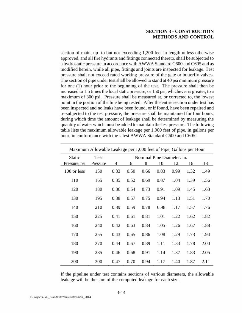
SECTION 3 - CONSTRUCTION METHODS AND CONTROL
3-14 H:\Projects\GG_Standards\Water\Revision_2014
section of main, up to but not exceeding 1,200 feet in length unless otherwise approved, and all fire hydrants and fittings connected thereto, shall be subjected to a hydrostatic pressure in accordance with AWWA Standard C600 and C605 and as modified herein, while all pipe, fittings and joints are inspected for leakage. Test pressure shall not exceed rated working pressure of the gate or butterfly valves. The section of pipe under test shall be allowed to stand at 40 psi minimum pressure for one (1) hour prior to the beginning of the test. The pressure shall then be increased to 1.5 times the local static pressure, or 150 psi, whichever is greater, to a maximum of 300 psi. Pressure shall be measured at, or corrected to, the lowest point in the portion of the line being tested. After the entire section under test has been inspected and no leaks have been found, or if found, have been repaired and re-subjected to the test pressure, the pressure shall be maintained for four hours, during which time the amount of leakage shall be determined by measuring the quantity of water which must be added to maintain the test pressure. The following table lists the maximum allowable leakage per 1,000 feet of pipe, in gallons per hour, in conformance with the latest AWWA Standard C600 and C605:
Maximum Allowable Leakage per 1,000 feet of Pipe, Gallons per Hour
Static
Test Nominal Pipe Diameter, in. Pressure, psi
Pressure 4 6 8 10
12
16 18
100 or less
150 0.33 0.50 0.66 0.83
0.99
1.32 1.49
110
165 0.35 0.52 0.69 0.87
1.04
1.39 1.56
120
180 0.36 0.54 0.73 0.91
1.09
1.45 1.63
130
195 0.38 0.57 0.75 0.94
1.13
1.51 1.70
140
210 0.39 0.59 0.78 0.98
1.17
1.57 1.76
150
225 0.41 0.61 0.81 1.01
1.22
1.62 1.82
160
240 0.42 0.63 0.84 1.05
1.26
1.67 1.88
170
255 0.43 0.65 0.86 1.08
1.29
1.73 1.94
180
270 0.44 0.67 0.89 1.11
1.33
1.78 2.00
190
285 0.46 0.68 0.91 1.14
1.37
1.83 2.05
200
300 0.47 0.70 0.94 1.17
1.40
1.87 2.11
If the pipeline under test contains sections of various diameters, the allowable leakage will be the sum of the computed leakage for each size.

SECTION 3 - CONSTRUCTION METHODS AND CONTROL
3-15 H:\Projects\GG_Standards\Water\Revision_2014
3-11.03 DISINFECTION
3-11.03.1 GENERAL
All water mains, water services, attached appurtenances and connections shall be disinfected in accordance with AWWA Standard C651-05 "Disinfecting Water Mains", State Water Resources Control Board, and as specified herein. Disinfection requirements shall include preventive and corrective measures during construction, final flushing, and bacteriological testing, and shall include the form of chlorine and methods of application The Contractor shall be solely responsible for the methods and techniques used to successfully disinfect the water mains and appurtenances and for disposing of the highly chlorinated water during flushing operations. Contractor shall furnish all equipment, labor, materials, safety requirements, and water necessary for chlorinating and flushing the pipeline. Disinfection of new mains, including all chlorination, chlorine residual measurements, collection of samples, and certification shall be conducted by a third party testing agency approved by the City. Gauges and apparatus used for chlorine injection shall bear the current State Certification. An independent State Certified Laboratory or authorized agent shall collect the samples and a State Certified Laboratory shall perform the bacteriological tests. All costs for disinfection, including laboratory fees, shall be paid by the Contractor.
At no time shall personnel other than the authorized third party testing agency be in charge of injecting chlorine into the water pipeline, the residual testing of the chlorine, or obtaining bacteriological samples.
Contractor shall ensure that all pipe, fittings, and appurtenances are kept free from dirt and foreign matter at all times. During construction all open pipe ends and fittings shall be fitted with a water tight plug. At the end of the work day the open pipe in the trench shall be plugged in an equally suitable manner.
The Contractor shall swab the interior surfaces of the new valves, pipes and appurtenances as well as interior surfaces of existing main, both upstream and downstream of the new pipe section, with a minimum

SECTION 3 - CONSTRUCTION METHODS AND CONTROL
3-16 H:\Projects\GG_Standards\Water\Revision_2014
five percent concentration of NSF approved hypochlorite disinfection solution before installation. During the chlorination or chlorinating process, all valves shall be operated, and the chlorine solution shall be drawn through all laterals and appurtenances. Disinfection of mains and appurtenances, hydrostatic testing, and chlorine retention may run concurrently for the required minimum 24-hour period only if prior approval is obtained from the Water Services Division and Water Quality Services Division.
In the event of leakage or where repairs are necessary, added disinfection shall be made only by injecting chlorine into the line whereby adequate mixing is assured. If the test results are not satisfactory, the Contractor shall provide additional disinfection, as required. Such additional disinfection shall be at the Contractor's expense. Disinfection of pipelines 4-inch or larger and in excess of 20-feet in length shall be accomplished by direct liquid chlorine as specified herein, unless otherwise approved by the Water Quality Services Division.
3-11.03.2 CHLORINE LIQUID FEED
The new system which is being disinfected shall be thoroughly pre-flushed, utilizing a minimum velocity of 2.5 feet per second throughout the entire system. The chlorinating agent shall be applied at a point not more than ten feet from the beginning of the section to be chlorinated and shall be injected through a corporation stop, a hydrant, or other approved connection to ensure treatment of the entire system being disinfected. All required corporation stops and other plumbing materials necessary for chlorination or flushing of all parts of the main being disinfected shall be installed by and at the expense of the Contractor.
Chlorine liquid shall be fed directly from the chlorine cylinder equipped with a suitable device capable of regulating the rate of flow and diffusion of liquid within the pipe. Water shall be concurrently fed into the pipe at a rate which produces a residual of not less than 50 (parts per million) PPM and not to exceed 100 PPM of chlorine in all sections of the pipeline and appurtenances being disinfected. Chlorinated water shall be retained in the system for a minimum duration of 24 hours, and shall produce at the end of the retention
SECTION 3 - CONSTRUCTION METHODS AND CONTROL
3-17 H:\Projects\GG_Standards\Water\Revision_2014
period not less than 25 PPM of chlorine in all sections of the pipeline being disinfected.
3-11.03.3 FINAL FLUSHING
Following the chlorination period of 24 hours, the newly laid line shall be thoroughly flushed to remove any foreign material. A suitable connection shall be provided by the Contractor at the end of each new line at the invert large enough to achieve a flushing velocity in the line of at least 2.5 feet per second.
Water shall be flushed from the line at its extremities and at all outlets
until the chlorine residual of the water system being flushed is equal to or less than the distribution system level.
3-11.03.4 DISINFECTION PROCEDURES WHEN CUTTING INTO OR
REPAIRING EXISTING MAINS The following procedures apply primarily when existing mains are wholly or partially dewatered. After the appropriate procedures have been completed, the existing main may be returned to service prior to completion of bacteriological testing in order to minimize the time customers are without water. Leaks or breaks that are repaired with clamping devices while the mains remain full of pressurized water may present little danger of contamination and therefore may not require disinfection. 1.Trench treatment. When an existing main is opened, either by accident or by design, the excavation will likely be wet and may be badly contaminated. Minimum of 12 inches of space shall be maintained between pipe and nearby soil. Plastic covering (6 mil minimum) shall be used under the pipe with gravel on top of it. Chlorine tablets shall be placed at the lowest point of the trench to lessen the danger from this contamination. 2. Swabbing with hypochlorite solution. The interior of pipe and fittings (particularly couplings and sleeves) used in making the repair shall be swabbed or sprayed with a 1 percent hypochlorite solution before they are installed. 3. Flushing. Thorough flushing is the most practical means of removing contamination introduced during repairs. If valve and hydrant locations

SECTION 3 - CONSTRUCTION METHODS AND CONTROL
3-18 H:\Projects\GG_Standards\Water\Revision_2014
permit, flushing toward the work location from both directions is recommended. Flushing shall be started as soon as the repairs are completed and shall be continued until discolored water is eliminated. 4. Slug chlorination. Where practical, in addition to the procedures previously described, the section of the main in which the break is located shall be isolated, all service connections shut off, and the section flushed and chlorinated. The dose may be increased to as much as 300 mg/L and the contact time reduced to as little as 15 min. After chlorination, flushing shall be resumed and continued until discolored water is eliminated and the chlorine concentration in the water exiting the main is no higher than the prevailing water in the distribution system or that which is acceptable for domestic use. 5. Bacteriological samples. Bacteriological samples shall be taken after repairs are completed to provide a record for determining the procedure's effectiveness. If the direction of flow is unknown, then samples shall be taken on each side of the main break. If positive bacteriological samples are recorded, then the situation shall be evaluated to determine corrective action. Daily sampling shall be continued until two consecutive negative samples are recorded.
3-11.03.5 SPECIAL PROCEDURE FOR CAULKED TAPPING SLEEVES Before a tapping sleeve is installed, the exterior of the main to be tapped shall be thoroughly cleaned, and the interior surface of the sleeve shall be lightly dusted with calcium hypochlorite powder. Tapping sleeves are used to avoid shutting down the main. After the tap is made, it is impossible to disinfect the annulus without shutting down the main and removing the sleeve. The space between the tapping sleeve and the tapped pipe is approximately 1/2 in. (13 mm), so that as little as 100 mg/ft2 of calcium hypochlorite powder will provide a chlorine concentration of more than 50 mg/L.
3-11.03.4 BACTERIOLOGICAL TESTS
After the system has been flushed, the Contractor shall have tests conducted for chlorine residual by a State Certified Laboratory approved by the City. Should the chlorine residual in any part of the disinfected system be higher than the distribution system level, the Contractor shall repeat the flushing procedure. If the chlorine residual
SECTION 3 - CONSTRUCTION METHODS AND CONTROL
3-19 H:\Projects\GG_Standards\Water\Revision_2014
after flushing is equivalent to or less than the distribution system level, the Contractor may proceed with the bacteriological sampling. Samples shall be taken at the direction of the Water Quality Services Division with at least one set of samples collected at 1,200-foot intervals along the new water main, plus one set at each dead-end main section, and at least one set from each branch (i.e., laterals 4-inch and larger). Two consecutive bacteriological samples are required for water quality evaluation. The first bacteriological sample shall be taken immediately after final flushing and the second sample shall be taken at least 24 hours later. All samples shall be collected by Certified Laboratory Personnel and tested for bacteriological quality in accordance with Standard Methods for the Examination of Water and Wastewater, and shall show the absence of coliform organisms.
The following tests are required to provide information for water quality evaluation:
1.) Presence/Absence of Total Coliform 2.) Heterotrophic Plate Count.
Report shall include:
a. Presence/Absence of Coliform Bacteria Count per 100 ml. b. Heterotrophic Plate Count per ml. c. Total and Free Chlorine Residual, taken at time of sample
collection by certified laboratory personnel.
All coliform test results must be negative. The heterotrophic plate count shall be 500 cfu / ml or less.
The results of these tests must be approved by the Water Quality prior to activating any new water facilities. Should the test results from the State Certified Laboratory disclose that the water from the new line does not meet the above standards, the disinfection process shall be repeated until it meets the required standards.
3-11.05 DISPOSAL OF TEST WATER
All water used in testing and disinfecting the portions of pipeline or water system component, including that used for retesting, shall be disposed of following such testing, retesting, and disinfecting by the Contractor at his sole expense. The disposal of water shall, in all cases, be carried out in compliance with the water

SECTION 3 - CONSTRUCTION METHODS AND CONTROL
3-20 H:\Projects\GG_Standards\Water\Revision_2014
quality objectives and discharge permit restrictions established by the California Regional Water Quality Control Board - Santa Ana Region.
For contracts administered by the City, the Contractor will be authorized to discharge test water to the storm drain under the National Pollution Discharge Elimination System (NPDES) permit issued to the City if all requirements and procedures per such permit are followed. For all other projects, including Developer projects, Contractor or Developer shall obtain an NPDES permit and comply with that permit.
Disposal of test water or chlorinated water used for disinfection will require the Contractor to apply a reducing agent (i.e. sodium thiosulfate, or ascorbic acid, etc.) to the test water in order to neutralize residual chlorine or chloramine to meet the discharge limitation. Additionally, the flow of water from the portions of pipeline shall be controlled to prevent erosion of surrounding soil, damage to vegetation, and altering of ecological conditions in the area and shall not contribute to silt, mud, debris, or other contaminants entering storm drains or surface waters. The Contractor’s attention is directed to the portion of the pipe with a low elevation. All water used in testing and disinfecting in that portion of the pipe shall be pumped out by the Contractor, at his expense, as specified in the paragraph hereinbefore. The Contractor shall furnish and operate all necessary pumps, pipelines, valves, hoses and all other appurtenances needed for pumping out water from the said low portion.
3-12 SPECIAL CONDITIONS
3-12.01 SHEETING AND SHORING
All trench excavation shall be adequately protected to provide a safe working condition, and protection to adjacent facilities and structures. The Contractor shall work in such a manner and install such protective devices, shoring, and bracing to comply with all rules, regulations, and orders of CAL-OSHA, Division of Industrial Safety.
Prior to any trench excavation where the depth is more than five feet, the Contractor shall submit a detailed plan to the Water Services Division showing the design of shoring, bracing, sloping, or other provisions to protect the workers from the hazard of caving ground during the excavation of such trench. If the plan varies from the shoring system standards, the plan shall be prepared by a Civil or Structural Engineer registered in the State of California. No excavation shall start

SECTION 3 - CONSTRUCTION METHODS AND CONTROL
3-21 H:\Projects\GG_Standards\Water\Revision_2014
until the Engineer has accepted the plan and the Contractor has obtained a permit from CAL-OSHA, Division of Industrial Safety. A copy of the permit shall be submitted to the Engineer and available at the job site at all times. Sheeting and shoring shall not place any undue strain on existing utilities or structures, nor on completed sections of construction. Sheeting and shoring may be removed during backfilling, provided adequate protection is provided at all times. The Contractor shall be responsible for any damage to existing utilities or structures due to placement, removal, or failure of any sheeting and/or shoring system. The Contractor shall repair or have repaired any damage as soon as practical.
3-12.02 JACKING OF STEEL CASING
Steel casing shall be placed at the location, elevations, and limits shown on the construction drawings. Known existing utilities shall be shown on the construction drawings. Any utilities or structures encountered which will interfere with construction shall be brought to the attention of the Water Services Division. Only new steel casing shall be used for jacking. Jacking shall be at a rate that will not over stress the casing, causing failure. Any damage to the casing during placement of the pipe shall be brought to the attention of the Water Services Division. The jacking and receiving pit shall be sheeted and shored as required by CAL-OSHA and as provided in Section 3-12.01 of these specifications. The excavated area ahead of the casing shall not be larger than 0.1 foot greater than the outside diameter of the casing. Over excavation beyond the above described limits shall be sanded or pressure grouted as directed by the Water Services Division. Sluicing or jetting ahead of the jacking casing shall not be permitted.
3-12.03 POLYETHYLENE PROTECTIVE WRAPPING
Unless otherwise noted on the plans, polyethylene protective wrapping (Polywrap) for ductile iron pipe shall be furnished and installed on all buried water lines, except where water lines are within a steel casing pipe, in accordance with the requirements of AWWA C105, Section 2-01.04 of these specifications, and as specified herein. Polywrap shall be installed so as to prevent any section of the pipe, fittings, valves, services, or appurtenances from contacting the soil. The 'polywrap' shall be taped to provide a snug fit along the pipe. Minimum tubing size shall allow for an overlap of 12 inches; i.e., flat tube width in inches = (3.14 X Diameter) + 12 inches. An additional 3 layer wrap of polyethylene shall be made at all tapping locations a minimum of 12 inches in width. Openings for service taps, blowoffs, or similar appurtenances shall be cut in the 'polywrap' during
SECTION 3 - CONSTRUCTION METHODS AND CONTROL
3-22 H:\Projects\GG_Standards\Water\Revision_2014
backfilling of the trench. Corporation stops and copper service lines shall be wrapped with polyethylene protective wrapping for a minimum clear distance of 3 feet from the water main. Any punctures, tears or other damage shall be patched with polyethylene wrap and tape in accordance with the requirements of AWWA C105 and manufacturer’s instructions. Rocks or other material that could damage the wrapping shall not be included in the backfill.
3-13 DEDICATION OF IMPROVEMENTS TO THE CITY
The Water Services Division may serve temporary construction water through facilities installed by the Contractor. This use shall be permitted following written confirmations from the laboratory conducting bacteriological tests that all samples meet the requirements of the Water Services Division. This use does not constitute acceptance of these facilities by the Water Services Division.
The Water Quality Services Division will serve domestic water through facilities installed by the Contractor after the following items are received.
1. Written confirmation from the laboratory conducting bacteriological tests that all
samples meet the requirements of the Water Quality Services Division.
2. Confirmation by the Water Services Division that all water improvements have been constructed per applicable specifications and plans. Contractor shall be responsible to maintain accurate records of any changes made during the course of construction and shall submit such information to the Water Services Division.
3. Public Utility Easements dedicated to the City, as required to gain access to public water
facilities located on private property.
4. Such agreements, fees, or other items as required by the Water Services Division.
Prior to serving domestic water through the installed facilities, the Developer shall present all deeds or instruments of conveyance to the Water Services Division and shall dedicate all water system improvements intended for public use to the City.
The Contractor shall warrant the quality of all material and workmanship for a period of one year from the date of acceptance of these facilities by the City. The Contractor shall make all repairs to facilities due to defect in material or construction method. Such repair shall not be the responsibility of the Water Services Division. If the Water Services Division's
SECTION 3 - CONSTRUCTION METHODS AND CONTROL
3-23 H:\Projects\GG_Standards\Water\Revision_2014
representative should deem the repair of such defective work an emergency situation, the Contractor shall be held liable for all costs required to correct such defective work.
3-14 AS-BUILT DRAWINGS
The Contractor shall provide and maintain a complete, legible, and accurate As-Built record set of prints. Such prints shall be kept up to date as work progresses and shall be maintained at the job site during construction. Progress payments for City of Garden Grove projects will not be processed until the As-Built drawings are reviewed and approved by the City.
As-Built drawings shall be prepared and shall show all changes in the work constituting deviations from the original contract drawings. All conceptual or major design changes shall be approved by the City before implementing the change in the construction contract.
Upon completion of the work, all required information, dimensions and adjustments to the original contract drawings shall be submitted to the City to be transferred to the record drawings. Facilities and items to be located and verified on the record drawings shall include the following:
a. Point of connections.
b. Utility locations.
c. Water mains: where deviations along installed water mains are more than ½ foot vertically and more than 1 foot horizontally, actual location (line and grade) shall be noted on the plans at intervals of 100 feet.
d. Services: where service tie-in differs from the plan station by more than 2 feet or when meter box is not perpendicular from the main, corporation stops shall be stationed. For all service lines that have directional changes, such as in the case of cul-de-sacs, the actual installation shall be noted regardless of field changes, and shall be adequately referenced to the satisfaction of the City Inspector.
e. Any material changes, including additions, deletions and substitutions.
f. Other related facilities, as required by the City Inspector
g. Contractor shall write on all sheets where the water improvements were built per plan that the construction was made “Per Plan”.
The City’s receipt and acceptance of As-Built drawings shall be a condition precedent to the
release of the Contractor’s retention/final payment. For projects constructed by Developers, the Water Services Division will not give final acceptance until approved “as-built” plans have been received.
SECTION 4 - LARGE SERVICES AND FIRE LINES
4-1
SECTION 4 - LARGE SERVICES AND FIRE LINES 4-01 GENERAL
All services larger than 2 inches in diameter installed for the purpose of obtaining water from the public system for domestic, irrigation, commercial or industrial consumption, or for fire protection shall be defined as large services. Large services installed for the purpose of providing fire protection only shall be further defined as Fire Lines.
Unless otherwise specified on the plans approved by the Water Services Division, all materials, construction methods and controls shall conform to the applicable sections of the Water Services Division Standard Specifications (WSDSS), which this section is a part thereof, including, but not limited to, Testing, Disinfection and Flushing.
4-02 DESIGN
The Developer or his Private Engineer or Contractor shall be responsible for preparation of the necessary design drawing showing the proposed large service installation together with meter and appurtenances. The drawing shall be prepared by a Registered Professional Civil Engineer licensed by the State of California, shall be submitted to the Water Services Division for review and must be approved prior to beginning construction. The drawing shall be prepared on an 8 ½" X 11" Standard Plan sheet furnished by the Water Services Division. The drawing shall show, but not be limited to, the following major items:
Street Name and Cross Street Name Station from C/L of Street Intersection Size, Type and Location of Street Main Public and Private Utilities Above and Below Ground Improvements and Cultures Scale and North Arrow Width of Street, Location of Curb, Sidewalk and Property Line Location and Size of Proposed Assembly For Vault installations identify Type of Vault and Cover Required (Traffic Bearing or Pedestrian) Easement, if required Size of Service Lateral and Meter Reference to Standard Detail Drawings

SECTION 4 - LARGE SERVICES AND FIRE LINES
4-2
4-03 FEES
The Water Services Division will require the payment of plan check and inspection fees concurrently with filing the application and submission of the drawing for review. A fee for checking, preparing and recording of easement documents, when applicable, will also be required prior to drawing approval. Fees shall conform to the latest revision of the User Fee Schedule prescribed by City Council resolution.
4-04 CONSTRUCTION AND INSPECTION
Upon approval by Water Services Division of the Service Application and Drawing for Large Service Installation, the Developer may proceed to award the work to a contractor of his choice.
The Contractor shall have a Class “C-34” or Engineering “A” Contractor’s License valid in the State of California and shall meet all the applicable requirements of the City of Garden Grove Municipal Code. The Contractor shall be responsible for obtaining all construction permits and licenses as may be required by those agencies having jurisdiction over the work area.
The Contractor shall notify the Water Services Division of his intent to commence work at least five (5) working days prior to starting construction. Inspection shall be provided by Water Services Division in accordance with Section 3-01 of these specifications.
4-05 EASEMENTS
The Water Services Division will advise the Developer at the time the application and drawings are first reviewed, if an easement for water utilities is required. Should an easement be required, the Developer or his Private Engineer shall be responsible for preparing a drawing and legal description on the appropriate form. The easement drawing and description shall be prepared by a Professional Land Surveyor licensed by the State of California and shall be submitted along with a copy of the property owner's last deed of record to the Water Services Division for checking and preparation of the Easement Deed. Execution of the Easement Deed, by the property owner, shall be required prior to drawing approval. A written waiver may be requested by the owner of the property on which the easement is required. In which case, the Execution of the Easement Deed, by the property owner, shall be required prior to final inspection and rendering of service by the Water Services Division.
SECTION 4 - LARGE SERVICES AND FIRE LINES
4-3
4-06 METERS
All Large Service installations shall include a meter and shall be located outside of the public right of way on private property, unless otherwise approved by the Water Services Division. Meters shall conform to size, type and manufacturer as shown on the Standard Drawings. Meters shall be compound type unless otherwise approved by the Water Services Division. The Water Services Division reserves the right to specify the type of meter if, in its sole opinion, a specific type of meter is best suited for the proposed application. Meters shall be provided with digital or direct reading registers with a full circle sweep hand, a leak indication dial, and shall read in cubic feet.
Minimum registration shall be as follows for the meter sizes stated:
2-3 inch meters CF X 10 4-8 inch meters CF X 100 10 inch and greater CF X 1,000
All Large Service installations, except Fire Lines, shall include provisions for a temporary bypass line per Standard Drawing B-724. All valves and fittings on the bypass line shall conform to Sections 2-05 and 2-08 of these specifications, respectively.
The Water Services Division, at its sole discretion, may require the bypass line to have OS&Y valves with handwheel operators and a permanent bypass spool. When OS&Y gate valves and spools are required by the Water Services Division on the bypass line, the hand wheel operators shall be secured in the closed position by a lock and chain.
4-07 VAULT INSTALLATIONS
All Large Services installed underground shall be installed in a concrete vault with an aluminum cover or as otherwise specified on the construction drawings. The dimensions of the vault, location of knock-out sections and the cover details shall be in strict conformance with this section and the application Detail Drawings contained in Section 6 of these specifications or as otherwise specified on the construction drawings.
The vault cover shall consist of one or two doors in one channel frame and shall open over the entire length and width of the vault. Door leaf shall be 1/4-inch aluminum diamond pattern plate to withstand a live load of 300 pounds per square foot. Channel frame shall be 1/4-inch aluminum. Door shall be equipped with heavy forged brass hinges, stainless steel pins, spring operators for easy operation, and an automatic hold open arm with release handle. A snap lock with removable handle shall be provided. Unless noted otherwise on the plans, hardware shall be mill finish with bituminous coating applied to the exterior of the frame. Stainless steel hardware may be required for installations in a highly corrosive environment. Manufacturer shall guarantee against defects in material and workmanship for a period of at least five years.

SECTION 4 - LARGE SERVICES AND FIRE LINES
4-4
An access ladder shall be provided for safe access in and out of vaults. An access ladder shall be constructed of Fiberglass Reinforced Plastic (FRP). The construction and installation of an FRP ladder shall meet all applicable requirements of CAL-OSHA. All vaults installed in areas subject to incidental vehicular traffic shall be steel reinforced concrete with an aluminum cover designed to meet a minimum traffic bridge loading of H-20, as defined by the American Association of State Highway Officials. As to type, materials, and hardware, traffic covers shall conform to the requirements specified in the preceding paragraph. In certain situations, guard posts may be required to prevent vehicular traffic from passing over the vault. When vaults are installed in areas subject to pedestrian traffic, the cover shall consist of non-skid materials as approved by the City Engineer.
4-08 THRUST RESTRAINT - VAULT INSTALLATION
A positive means of thrust restraint shall be provided on the inlet line to a vault installation so that the pipe at the last joint, prior to entering the vault, is physically restrained from movement in the direction of the vault. See Standard Plan B-713.
4-09 PAINTING - ABOVE GROUND INSTALLATIONS
After ALL Testing and Disinfection has passed, but prior to Final Acceptance by the Water Services Division, all above ground Large Service installations shall be painted in accordance with Section 2-14.
4-10 AESTHETICS - ABOVE GROUND INSTALLATIONS
Above ground Large Services shall be screened from public view by landscape plants and/ or walls as per Utility Equipment Screening Standards and Specifications for Above-ground Equipment on Private Property or other appropriate means as directed by the Planning Services Division. Landscape plants shall be a minimum of 15-gallon each in size, and the same type as the existing landscape plants in surrounding area to blend with the local environment. If a screen wall is proposed, landscaping including clinging vines shall be planted to soften the wall and discourage graffiti. If such wall is adjacent to a structure, the wall may also be required to be painted to match the exterior of the structure, if determined necessary by the Planning Services Division. The above ground service shall be located and shielded from view per Standard Plan B-769. Whichever method of concealment is used, it shall not obscure or hinder access to the Fire Department's pumper connection. Within the confines established by the Fire Department, Planning Services Division and Water Services Division, the owner/developer shall locate all above ground large services in a manner that is aesthetically pleasing. Additional conditions may be required for specific projects in order to comply with local ordinances and zoning codes. The owner/developer
SECTION 4 - LARGE SERVICES AND FIRE LINES
4-5
shall submit the location and method of screening of the above ground services to the Fire Department, Planning Services Division, and Water Services Division for review and approval.
It shall be the owner’s responsibility to irrigate and maintain planted landscape screening in a healthy state and to trim and prune them such that access to the device is not impaired. If owner fails to maintain landscape plants and paint in the desired state, the City will cause such work to be performed and owner will be billed for the actual cost of performing the work plus ten percent for overhead and administration. Failure to pay for said work, when due, shall be cause for termination of service.

G:\GG-ENGG\data\acaddata\New-GG-STD\2013 Standard Plans\Standard Specs\2015 Water Specs\5 Section 2014_rv02.doc
5-1
SECTION 5 – BACKFLOW PREVENTION
5-01 BACKFLOW PROTECTION
All water services connected to the public water system may be required to include an approved backflow prevention device of the type designated by the Water Quality Services Division. The type of device approved shall be based on the existing or potential degree or hazard which exists, in the opinion of the Water Quality Services Division. All devices shall be approved by the Foundation for Cross-Connection Control and Hydraulic Research, University of Southern California, Los Angeles, CA 90089-2531. The Developer or his Contractor shall be responsible for the installation, initial test and certification of all new or relocated backflow prevention devices. Thereafter, backflow prevention devices will be maintained and tested annually by the owner or water user. The backflow prevention device installation shall be above ground, screened from view as approved by the Planning Services Division and Water Services Division, and shall conform to Sections 4-09, 4-10, and Section 6 of these Specifications.
When an existing backflow prevention device that is located in public right-of-way needs to be replaced, a new device shall be required to be installed above ground on private property. Unless otherwise approved by the Water Services Division, the entire section of piping between the water main and the new device shall be replaced with new pipe. In addition, design plans for the new device, and accompanying plan check and inspection fees shall be submitted to the Water Services Division for review and approval in accordance with Section 4 of these specifications. Backflow prevention devices shall be located above ground and as close as practical to the meter or to the street right-of-way line, and subject to approval by the Water Quality Services Division. The entire length of underground piping from the meter or the street right-of-way line to the Backflow Prevention Device shall be backfilled with one-sack slurry 12 inches minimum thickness over the top of the pipe zone (bedding), unless other means/methods are approved by the Water Services Division.

SECTION 5 - BACKFLOW PREVENTION
G:\GG-ENGG\data\acaddata\New-GG-STD\2013 Standard Plans\Standard Specs\2015 Water Specs\5 Section 2014_rv02.doc
5-2
5-01.01 APPROVED MANUFACTURERS
Any backflow prevention devices approved by the Foundation for Cross-Connection Control and Hydraulic Research, University of Southern California, Los Angeles, CA 90089-2531, as shown on the latest edition of "List of Approved Backflow Prevention Assemblies".
5-02 FIRE LINE ASSEMBLY All fire line assemblies shall require a detector meter and backflow protection as
may be determined by the Water Quality Services Division. All fire lines shall be installed in conformance with Section 6 of these Specifications and/or as directed by the Fire Department and Water Services Division. Vault installation of fire line assemblies is prohibited.
For assemblies that require a detector meter, the meter shall be 5/8 or 3/4 inch nominal size with bronze case and shall have a straight read magnetic drive register capable of detecting increments of consumptive use in one cubic foot increments.