addendum 1 specs.pdf - nassau university medical center
TRANSCRIPT

Nassau University Medical Center - Basement Addendum 1 - June 5, 2013Medical Records Relocation
HEATING, VENTILATING & AIR CONDITIONING INDEX 23 00 00 - 1
DIVISION 23 - HEATING, VENTILATING & AIR CONDITIONING INDEX
SECTION 23 05 00 COMMON WORK RESULTS FOR HVACSECTION 23 05 13 COMMON MOTOR REQUIREMENTS FOR HVAC EQUIPMENTSECTION 23 05 15 VARIABLE FREQUENCY CONTROLLERSSECTION 23 05 47 VIBRATION ISOLATION (NON SEISMIC)SECTION 23 05 48 FOUNDATIONS, VIBRATION ISOLATION & SUPPORTS FOR
RIGIDLY SUPPORTED EQUIPMENT (SEISMIC DESIGN)SECTION 23 05 50 BASIC MECHANICAL MATERIALS AND METHODSSECTION 23 05 93 TESTING, BALANCING AND ADJUSTINGSECTION 23 07 00 HVAC INSULATIONSECTION 23 07 20 ACOUSTICAL DUCT LINING AND DUCT WRAPSECTION 23 09 00 HVAC INSTRUMENTATION AND CONTROLSSECTION 23 09 93 SEQUENCE OF OPERATIONS FOR HVAC CONTROLS
BMS POINTLISTSECTION 23 09 95 ENCLOSED CONTROLLERSSECTION 23 21 13 HVAC PIPINGSECTION 23 25 00 CHEMICAL WATER TREATMENTSECTION 23 31 13 METAL DUCTWORKSECTION 23 33 10 SOUND ATTENUATIONSECTION 23 33 13 DAMPERSSECTION 23 33 50 AIR FILTERSSECTION 23 34 00 FANSSECTION 23 37 15 AIR DISTRIBUTION DEVICESSECTION 23 73 13 CENTRAL STATION AIR HANDLING UNITSSECTION 23 73 14 CUSTOM AIR HANDLING UNITS – FACTORY FABRICATED /
SITE ASSEMBLEDSECTION 23 81 22 SUPPLEMENTAL AIR CONDITIONING UNITS (AIR COOLED)
X:\SPECS\120216\ADD NO. 1 - JUNE 5, 2013\HVACINDEX.DOC

Nassau University Medical Center - Basement Addendum 1 - June 5, 2013Medical Records Relocation
VIBRATION ISOLATION (NON SEISMIC) 23 05 47 - 1
SECTION 23 05 47 - VIBRATION ISOLATION (NON SEISMIC)
PART 1 - GENERAL
1.1 SECTION INCLUDES
A. Vibration control.
B. Description of Work
1. It is the objective of this specification to provide the necessary designrequirements for the control of excessive noise and vibration in buildings due tothe operation of machinery or equipment, and/or due to interconnected piping,ductwork or conduit.
2. Provide vibration isolation systems, complete as shown and specified perContract Documents.
3. The work of this section includes, but is not limited to, the following:
a. Vibration isolation elements for piping and equipment;b. Equipment isolation bases;c. Piping flexible connections;
1.2 RELATED DOCUMENTS
A. Drawings and general provisions of the Contract, including General and SupplementaryConditions and other Division 01 Specification Sections, apply to this Section.
B. Section 23 05 00 - Common Work Results for HVAC
C. Section 23 05 50 - Basic Mechanical Materials and Methods.
D. This section is a part of each Division 23 Section.
1.3 REFERENCES
A. ASHRAE.
1.4 QUALITY ASSURANCE
A. Applicator: Products provided by company specializing in vibration isolation with tenyears minimum experience.
B. All vibration isolation devices shall be the product of a single manufacturer. Products ofother manufacturers are acceptable, provided that their systems comply with the designintent for system performance, static deflection and structural design of the basemanufacturer.
C. The following are approved manufacturers, provided their systems strictly comply withthe design intent for performance, deflection and structural capacity of this specification.

Nassau University Medical Center - Basement Addendum 1 - June 5, 2013Medical Records Relocation
VIBRATION ISOLATION (NON SEISMIC) 23 05 47 - 2
1. Mason Industries, Inc. Hauppauge, NY
2. Vibration Mountings & Controls Bloomingdale, NJ
3. Kinetics Company, Dunlin, OH
4. Korfund Dynamics Corp., Bloomingdale, NJ
5. Vibration Eliminator Co., Inc., Long Island City, NY
6. Amber Booth, Houston, TX
D. Vibration isolation firms having a minimum of ten (10) years experience in designing andinstalling vibration isolation systems shall be qualified to provide the materials andinstallation required by this section. Project listings shall be provided includinggeographical location and a reference contact.
1.5 SUBMITTALS
A. Submit product data under provisions of Section 01 30 00.
B. Include product description, list of materials for each service, and locations.
C. Submit manufacturer's installation instructions under provisions of Section 01 30 00.
D. Vibration isolation equipment submittal drawings shall include the following information:
1. Isolation mounting deflections.
2. Spring diameters, compressed spring heights at rated load; solid spring heights,where steel spring isolation mountings are used.
3. Equipment operating speed.
E. In addition to the requirements on Mechanical General Provisions, the submittal materialshall include thirteen (13) copies of descriptive data for all products and materialsincluding, but not limited to, the following:
1. Descriptive Data:
a. Catalog cuts and data sheets on specific vibration isolators to be utilizedshowing compliance with the specifications.
b. An itemized list showing the items of equipment or piping to be isolated,the isolator type and model number selected, isolator loading anddeflection.
2. Shop Drawings:
a. Drawings showing equipment base constructions for each machine,including dimensions, structural member sizes and support pointlocations.

Nassau University Medical Center - Basement Addendum 1 - June 5, 2013Medical Records Relocation
VIBRATION ISOLATION (NON SEISMIC) 23 05 47 - 3
b. Drawings showing methods of suspension, support guides for piping andductwork.
c. Drawings showing methods for isolation of pipes and ductwork piercingwalls and slabs.
d. Concrete and steel details for bases, including anchor bolt locations.
PART 2 - PRODUCTS
2.1 FLOOR MOUNTING OF CENTRIFUGAL FANS AND TUBULAR ARRANGEMENT ONEFANS - MOUNTING TYPE I
A. Each such fan and driving motor shall be mounted on an integral one piece structuralbase, reinforced as necessary to prevent flexure of the base at start up and duringoperation of the fan. The unitized structural base for the fan and motor shall includemotor slide rails. The structural steel frame shall be drilled and tapped to receive the fanand motor so that the frame shall act as a template. Provide vertical limit stops suitablefor applicable wind loads where exposed.
B. The structural steel integral base shall be supported on steel spring mountings. Thesemountings shall be positioned in accordance with the weight distribution to ensure ade-quate deflection and vibration isolation. Housing or snubbing devices shall not be usedto contain the isolation springs.
C. Isolator types shall be one of the following or as approved:
Type SL - M.I.I.Type OSK - V.E.C.Type AN - V.M.C.I.
2.2 MOUNTING OF FLOOR MOUNTED PACKAGED AIR HANDLING UNITS, MOUNTINGTYPE V
A. This equipment shall be mounted directly on stable bare steel spring isolators, exceptthat where the units to be mounted are furnished with internal structural frames andexternal lugs (both of suitable strength and rigidity), or without any severe overhangs, noadditional structural frame need be furnished and installed beneath the unit. In anyevent, the motor shall be integrally mounted to the unit and shall be mounted on sliderails. Mounting types shall be as described for TYPE I.
B. Minimum static deflection shall be 1".
2.3 MOUNTING OF CEILING SUPPORTED PACKAGED AIR HANDLING UNITS,TUBULAR ARRANGEMENT 9 FANS, & BELTED VENT SETS - MOUNTING TYPE VI
A. All such units shall be hung by means of vibration isolator hangers consisting of a steelhousing or retainer incorporating a steel spring and neoprene mounting.
B. If the equipment to be mounted is not furnished with integral structural frames andexternal mounting lugs (both of suitable strength and rigidity), approved structural sub-base shall be installed in the field which shall support the equipment to be hung and towhich shall be attached to the hangers.
C. Isolators shall be one of the following or as approved:

Nassau University Medical Center - Basement Addendum 1 - June 5, 2013Medical Records Relocation
VIBRATION ISOLATION (NON SEISMIC) 23 05 47 - 4
Type 30N - M.I.I.Type 30 - V.M.C.I.Type SNRC-4 - V.E.C.
D. Diagonal hanger rod isolators shall be provided as required to limit horizontal motion to1/4 inch maximum under fan operating conditions.
2.4 PIPING GUIDES
A. Type ADA Mason Industries or as approved.
2.5 ACOUSTICAL ANCHORS
A. Type VPA Mason industries or as approved.
2.6 PIPING SUPPORTS
A. All water piping hanger rod isolators shall be one of the following or as approved:
Type PC30 - M.I.I.Type VSHL - V.M.C.I.Type TK - V.E.C.Type VXPM - K.D.C.
B. Floor supported water piping shall be mounted on one of the following or as approved:
Type SLR - M.I.I.Type AWR - V.M.C.I.Type KW - V.E.C.
C. Mountings for the support of ceiling suspended steam and condensate piping shall beone of the following or as approved:
Type RHD - V.M.C.I.Type HD - M.I.I.Type CD - V.E.C.
D. Floor supported steam and condensate piping including steam pressure reducingstations shall be mounted on one of the following or as approved:
Type ND - M.I.I.Type RD - V.M.C.I.Type 368SD - V.E.C.
PART 3 - EXECUTION
3.1 GENERAL
A. All equipment, piping, etc. shall be mounted on or suspended from approved foundationsand supports, all as specified herein, or as shown on the drawings.

Nassau University Medical Center - Basement Addendum 1 - June 5, 2013Medical Records Relocation
VIBRATION ISOLATION (NON SEISMIC) 23 05 47 - 5
B. All concrete foundations and supports (and required reinforcing and forms) will befurnished and installed by another trade. However, this trade shall furnish shopdrawings showing adequate concrete reinforcing steel details and templates for allconcrete foundations and supports, and all required hanger bolts and otherappurtenances necessary for the proper installation of his equipment. Although anothertrade will complete all concrete work, all such work shall be shown in detail on the shopdrawings, prepared by this trade which drawings shall be submitted showing thecomplete details of all foundations including necessary concrete and steel work,vibration isolation devices, etc.
C. All floor-mounted equipment shall be erected on 4" high concrete pads over thecomplete floor area of the equipment, unless specified to the contrary herein. Whereverhereinafter vibration eliminating devices and/or concrete inertia blocks are specified,these items shall, in all cases, be in turn mounted upon 4" high concrete pads unlessspecified to the contrary herein.
D. The vibration isolation systems shall be guaranteed to have the deflection indicated onthe schedule on the drawings. Mounting sizes shall be determined by the mountingmanufacturer, and the sizes shall be installed in accordance with the manufacturer'sinstructions.
E. The installed vibration isolation system for each floor or ceiling supported equipmentshall have a maximum lateral motion under equipment start-up or shut down conditionsof 1/4 inch. Motions in excess shall be restrained by approved spring type mountings.
F. All mounting systems exposed to weather and other corrosive environments shall beprotected with factory corrosion resistance. All metal parts of mountings (except springsand hardware) to be hot dip galvanized. Springs shall be cadmium plated and neoprenecoated. Nuts and bolts shall be cadmium plated.
G. Where steel spring isolation systems are described in the specifications, the mountingassemblies shall utilize bare springs with the spring diameter not less than 0.8 of theloaded operating height of the spring. Each spring isolator shall be designed andinstalled so that the ends of the spring remain parallel during and after the springinstallation. All isolators shall operate in the linear portion of their load versus deflectioncurve and have 50% excess capacity without becoming coil bound.
3.2 SUPPORT OF PIPING
A. The following water, steam and condensate piping shall be resiliently supported:
1. All piping in equipment room.
2. Piping outside of equipment room within 50 feet or 100 diameters whichever isgreater of connected rotating equipment.
3. All steam piping.
B. Resilient diagonal mountings or other approved devices shall be provided as required tolimit piping motion due to equipment startup or shut down, to a maximum of 1/8 inch.

Nassau University Medical Center - Basement Addendum 1 - June 5, 2013Medical Records Relocation
VIBRATION ISOLATION (NON SEISMIC) 23 05 47 - 6
C. Water piping hanger rod isolators shall contain a steel spring in series with a 1/4 inchacoustical neoprene pad within a steel box retainer. The hanger rod isolator assemblyshall be rigidly supported from the building structure. The installed hanger rod supportedfrom the spring sub assembly shall not contact the steel box retainer and clearances inthe isolator design shall be capable of accepting a 15 misalignment in any direction fromthe vertical.
D. The steel spring element of the assembly shall be designed to have a minimum surgefrequency of 340 HZ and a minimum deflection of 3/4 inch.
E. Hanger rod isolators for steam and condensate piping including steam pressurereducing valve stations shall be supported by meals of neoprene-in-shear mountingsproviding a minimum static deflection of 2 inch.
F. Where supplementary steel is required to support piping, the supplementary steel shallbe sized so that maximum deflection between supports does not exceed 0.08 inchesand shall be resiliently supported from the building structure with mountings asdescribed above. Supported piping from the supplementary steel shall be rigidlysuspended or supported.
G. Precompressed type hanger rod isolators shall be provided for all water piping greaterthan 12 inch diameter and all supplementary steel supports. The precompression shallbe factory set at 75% of rated deflection.
H. Where isolated water piping 8" and larger is supported directly below exposed steelbeams, attachment to the beam shall be made by means of welded channel beamattachments located directly under the web of the beam. For piping 6" and smaller beamclamps may be used in lieu of welding subject to approval of beam clamp selection.
3.3 MAIN CHILLED WATER PIPING ANCHORS, GUIDES & SUPPORTS
A. Pipe riser guides, anchors and supports including piping anchors in mechanicalequipment rooms or occupied spaces shall be isolated from the building structure suchthat there shall be no direct metal to metal contact of the piping with the buildingstructure.
3.4 PIPING GUIDES
A. Steel guides shall be welded to the pipe at a maximum spacing of 90. The outsidediameter of the opposing guide bars shall be smaller than the inside diameter of the piperiser clamp in accordance with standard field construction practice. Each end of the pipeguide shall be rigidly attached to an all directional pipe anchor isolation mounting whichin turn, shall be rigidly fastened to the steel framing within the shaft. See Detail onDrawings.
B. The all directional pipe anchor isolation mountings shall consist of a telescopingarrangement of two sizes of steel tubing separated by a minimum of 2 inch thick heavyduty neoprene and canvas duck isolation pad. Vertical restraints shall be provided bysimilar material arranged to prevent vertical travel in either direction. The allowable loadon the isolation material shall not exceed 500 psi.
C. Mountings shall be Type ADA - Mason Industries, Inc., or as approved.

Nassau University Medical Center - Basement Addendum 1 - June 5, 2013Medical Records Relocation
VIBRATION ISOLATION (NON SEISMIC) 23 05 47 - 7
D. Low temperature piping guides shall be constructed with a 360 10 gauge metal sleevearound the piping. The thermal insulation requirements for the piping shall be providedbetween the piping and the sleeve. Heavy duty neoprene and canvas duck isolation padof thickness equal to thermal insulation requirements shall space the metal sleeve awayfrom the piping with urethane or other suitable thermal insulation provided in the voidsbetween the pipe-sleeve and isolation pan material. The metal sleeve outside diametershall be smaller than the pipe riser clamp inside diameter in accordance with standardfield construction practice. The pipe riser clamp shall be rigidly attached to the steelframing within the shaft.
3.5 ANCHORS
A. The pipe riser clamp at anchor points, shall be welded to the pipe and to pairs of verticalacoustical pipe anchor mountings which in turn, shall be rigidly fastened to the steelframing in the pipe shaft.
B. Acoustical pipe anchor mountings shall be Type VPA Mason Industries, Inc., or asapproved.
3.6 SUPPORTS
A. Piping supports within shafts shall be provided with suitable bearing plates and twolayers of 1/4 inch thick ribbed or waffled neoprene pad loaded for 50 psi maximum. Theisolation pads shall be separated with 1/4 inch steel plate.
B. The isolation pads shall be one of the following or as approved:
Type W - M.I.I.Type Shearflex - V.M.C.I.Type 200N - V.E.C.
C. Piping isolation supports at the base of risers shall be two layers of 2 inch thick heavyduty neoprene and canvas duck isolation pad separated by 1/4 inch thick steel plate.Suitable bearing plates sized to provide a pad loading of 500 psi maximum shall beprovided. The stanchion between the pipe and isolation support shall be welded to thepipe and welded or bolted to the isolation support. The isolation support shall be boltedto the floor slab with resilient sleeves and washers.
D. All pipe support resilient materials shall be HL Mason Industries, Inc., or as approved.
3.7 SHEET METAL & PIPING PENETRATIONS OF SHAFTS, FLOOR SLAB AND/ORPARTITIONS
A. There shall be no direct contact of Sheet Metal or piping with shaft walls, floor slabsand/or partition. All uninsulated sheet metal or piping shall be packed with caulking thefull depth of the penetration.

Nassau University Medical Center - Basement Addendum 1 - June 5, 2013Medical Records Relocation
VIBRATION ISOLATION (NON SEISMIC) 23 05 47 - 8
3.8 SCHEDULE
A. See drawings.
END OF SECTION 23 05 47
X:\Specs\120216\Add No. 1 - June 5, 2013\23 05 47 Vibration Isolation (Non Seismic).doc

Nassau University Medical Center - Basement Addendum 1 - June 5, 2013Medical Records Relocation
HVAC INSTRUMENTATION AND CONTROLS 23 09 00 - 1
SECTION 23 09 00 - HVAC INSTRUMENTATION AND CONTROLS
PART 1 - GENERAL
1.1 RELATED DOCUMENTS
A. Drawings and general provisions of Contract, including General and SupplementaryConditions and Division 01 Specification Sections, apply to this Section.
1. Section 23 05 00 - Common Work Results for HVAC.
2. Section 23 05 50 - Basic Mechanical Materials and Methods.
3. This section is a part of each Division 23 Section (Mechanical).
4. Specified elsewhere:
5. Variable Speed Control
6. Motors
7. HVAC Pumps
8. Terminal Heat Transfer Units
9. Fans
10. Air Handling Units
11. Testing, Adjusting and Balancing
12. Basic Elec. Materials Methods
13. Electrical Wiring
B. Technical Proposals
1. Technical proposals shall be prepared in accordance with these specifications.Four (4) copies of the proposal shall be submitted with the bid. Proposals thatare unbound, loose, loose in a file folder, stapled, stapled in a manila file folder,etc., will not be acceptable. The technical proposal shall include the followingdata/information as a minimum. The order of listing here is not intended toindicate, nor should it be construed to indicate, the relative importance of thedata/information:
a. Information on organizational capability to handle this project(management, personnel, manufacturing, single source responsibility,etc.). Provide an organizational chart of the local factory branch officeindicating the project team and each person=s role in the project. Providea resume for each project team member and all management personnel.
Nassau University Medical Center - Basement Addendum 1 - June 5, 2013Medical Records Relocation
HVAC INSTRUMENTATION AND CONTROLS 23 09 00 - 2
b. A comprehensive bar chart project schedule indicating submission ofshop drawings, equipment delivery, installation, start-up commissioning,training, milestones, and all critical path tasks.
c. A project specific on-site and off-site training program whichdemonstrates specification compliance.
d. BMS Configuration as Proposed:
2. Modularity.
3. Provisions against obsolescence due to technological advancement.
4. Detailed description of all operating, command, application and energymanagement software provided for this project.
5. Provide a riser drawing of the system architecture. The drawing shall indicatethe model number, location and service of each primary control panel, secondarycontrol panel, and all other network hardware.
6. A complete description of all interface and/or integration packages.
7. Provide a complete submittal of all hardware, software, sensors and end devices(valves, damper operators, airflow stations, etc.).
8. Description of manual override operation and BMS monitoring of manual overrideoperation and BMS monitoring of manual override for each type control point insystem.
9. A list of references (include Owner contact name and phone number) for five (5)projects completed by the local branch office within the last five years of similarsize, schedule and complexity.
10. A signed certificate stating the Contractor Ahas read the performance andfunctional requirements, understands them, and the technical proposal willcomply with all parts of the specification@ or a signed line by line specificationconcordance statement. Certificate or statement shall be signed by a personhaving the authority to guarantee the statement.
1.2 SUMMARY
A. General Work Description
1. Building Management System (BMS) controls contractor shall provide:
a. A fully integrated expansion to the existing Johnson Controls BranchOffice Metasys Extended Architecture Building Management System(BMS). All new components shall be UL-listed and incorporate directdigital control (DDC) for energy management, equipment monitoring, andHVAC control.
b. Electronic sensors.

Nassau University Medical Center - Basement Addendum 1 - June 5, 2013Medical Records Relocation
HVAC INSTRUMENTATION AND CONTROLS 23 09 00 - 3
c. Actuators of terminal equipment valves and dampers shall be electric. Allsensors shall be electric/electronic.
d. Actuators for valves and dampers located within the MER=s shall beelectric.
e. All line voltage and low voltage wiring, conduit, panels, and accessoriesfor a complete operational system. All final electrical connections to eachstand-alone DDC Controller.
f. BMS Contractor shall be responsible for all electrical work associated withthe BMS and as shown in the contract documents. The BMS contractorshall be responsible for all electrical work associated with any BMSinterface to any other systems including but not limited to HVAC andplumbing systems.
g. The BMS contractor shall furnish all wells for water monitoring devices,flow switches, and alarms.
h. A complete operational system including all work required for acompletely operational system as defined in the entire set of drawingsand specifications, including but not limited to associated specificationsfor mechanical and electrical work, all contract drawings, BMS Point List,and remote function schedule.
i. The BMS system as a whole shall have the capability to be easilyexpanded through the addition of point modules and/or controllers. Noequipment shall be installed which cannot, as installed, accommodate anupgrade the entire system by at least 25%. A 25% system upgrade shallinclude 25% more points (of each type) either via point modules orcontrollers and 25% more memory capacity for future connections.
j. Provide appropriate labor jurisdiction to mount, wire and pipe airflowmeasuring stations in the field. Provide manpower as required to meetproject schedule.
1.3 DEFINITIONS
A. AI - Analog Input
B. ANSI - American National Standards Institute
C. AO - Analog Output
D. ASCII - American Standard Code for Information Interchange
E. AWG - American Wire Gauge
F. BMS - Building Management System
G. CPU - Central Processing Unit

Nassau University Medical Center - Basement Addendum 1 - June 5, 2013Medical Records Relocation
HVAC INSTRUMENTATION AND CONTROLS 23 09 00 - 4
H. CRT - Cathode Ray Tube
I. DAC - Digital to Analog Converter
J. DDC - Direct Digital Control
K. DI - Digital Input
L. DO - Digital Output
M. EEPROM Electronically Erasable Programmable Read Only Memory
N. EMI - Electromagnetic Interference
O. FAS - Fire Alarm Detection and Annunciation System
P. HOA - Hand-Off-Auto
Q. IEEE - Institute of Electrical and Electronics Engineers
R. I/O - Input/Output
S. LAN - Local Area Network
T. LCD - Liquid Crystal Display
U. LED - Light Emitting Diode
V. MCC - Motor Control Center
W. NC - Normally Closed
X. NO - Normally Open
Y. OWS - Operator Workstation
Z. OAT - Outdoor Air Temperature
AA. PC - Personal Computer
BB. RAM - Random Access Memory
CC. RFI - Radio Frequency Interference
DD. RH - Relative Humidity
EE. ROM - Read Only Memory
FF. RTD - Resistance Temperature Detector
GG.TCP/IP- Transmission Control Protocol/Internet Protocol
HH. UPS - Uninterruptible Power Supply

Nassau University Medical Center - Basement Addendum 1 - June 5, 2013Medical Records Relocation
HVAC INSTRUMENTATION AND CONTROLS 23 09 00 - 5
II. VAC - Volts, Alternating Current
JJ. VAV - Variable Air Volume
KK. VDC - Volts, Direct Current
LL. WAN - Wide Area Network
1.4 SYSTEM DESCRIPTION
A. General Product Description
1. The building management system (BMS) shall integrate multiple buildingfunctions including equipment supervision and control, alarm management,energy management and historical data collection.
2. The building management system shall consist of the following:
a. Independent, Primary Control Panels (PCPs) for global control strategies,system wide DDC commands, alarm management, data accumulation,etc. The intent of this specification is that the loss of any one PrimaryControl Panel shall affect only the points and/or network connected to thatspecific Primary Control Panel and shall not affect the operation of anyother Primary Control Panels.
b. Fully programmable, stand-alone, Secondary Control Panels for control ofeach air handler. Application specific terminal equipment controllers shallcontrol all terminal equipment such as VAV, etc. Motors shall becontrolled only from Secondary Control Panel associated with therespective HVAC system.
3. The system shall be modular in nature and shall permit expansion of bothcapacity and functionality through the addition of sensors, actuators, PrimaryControl Panels, Secondary Control Panels and operator devices.
4. System architectural design shall eliminate dependence upon any single devicefor alarm reporting and control execution. Each Primary Control Panel shalloperate independently by performing its own specified control, alarmmanagement, operator I/O and data collection. The failure of any singlecomponent or network connection (including a wire break) shall affect only thesystem controlled by the specific PCP and shall not interrupt the operation of anyother SCP, PCP, etc. In addition, the failure shall not affect or interrupt theexecution of any control strategy, reporting, alarming and trending function, orany function at any operator interface device.
5. Primary Control Panels shall be able to access any data from, or send controlcommands and alarm reports directly to, any other Primary Control Panels orcombination of Primary Control Panels on the network without dependence upona central or intermediate processing device. Primary Control Panels shall alsobe able to send alarm reports to multiple operator workstations withoutdependence upon a central or intermediate processing device.

Nassau University Medical Center - Basement Addendum 1 - June 5, 2013Medical Records Relocation
HVAC INSTRUMENTATION AND CONTROLS 23 09 00 - 6
6. Operators shall be able to assign password access and control priorities to eachHVAC system or interfaced system individually. The logon password (at any PCworkstation or portable operator terminal) shall enable the operator to monitor,adjust and control only the system that the operator is authorized for. All othersystems shall not be displayed at the PC workstation or portable terminal.Passwords and priority levels for every system shall be fully programmable andadjustable. This provision shall be applicable to all systems accessed eitherlocally or remotely.
1.5 SEQUENCE OF OPERATION
A. Refer to Section 23 09 93 for Sequence of Operations for HVAC Controls.
1.6 SUBMITTALS
A. General
1. Indicate at the beginning of each submittal, all substitutions and deviations fromrequirements of Contract Documents.
B. Product Data
1. Technical bulletins and catalog data for all equipment and system components.Clearly identify, by use of symbol or tag number, the service of each item. Allirrelevant information shall be marked out leaving only pertinent data.
C. Shop Drawings
1. Shop drawing submittals shall comply with Division 01 and other specifiedrequirements and shall include sufficient data to indicate complete compliancewith Contract Documents. Submission shall be in the form of drawings,brochures, bulletins, catalog data and/or narrative descriptions.
2. Submission shall include, but not be limited to:
a. Symbol and abbreviation lists.
b. System block diagram showing quantity and location of personal operatorworkstation(s), Primary Control Panels, Secondary Control Panels, andlocations of power feeds to BMS and other major system components.
c. Control diagrams for all systems controlled. Controls shall be shown onsystem flow diagrams.
d. Power wiring diagrams and electrical requirements.
e. Interfaces (software and hardware) with other equipment provided inother sections of specifications including but not limited to chiller controlsystem.

Nassau University Medical Center - Basement Addendum 1 - June 5, 2013Medical Records Relocation
HVAC INSTRUMENTATION AND CONTROLS 23 09 00 - 7
f. Narrative description of operation for each system, enumerating anddescribing the function of each component. Include alarm andemergency sequences, and equipment interlocks.
g. Description of manual override operation for every input and output point.
h. Complete input/output point schedule. Identify point function, type andlocation.
i. Spare capacity provisions.
j. Detailed bill of materials.
k. Valve and damper schedule: Provide identification numbers, location,system, dimensions and performance data. Include damper leakagerates.
l. Device mounting details. Include as a minimum:
(i) Sensing elements in ducts and casings.
(ii) Sensing elements in piping.
m. Ladder wiring diagrams.
n. Other information as requested herein.
o. Complete full size drawings, 11" x 17" minimum.
D. Programming
1. Point identification code.
2. System advisory messages, printouts, logging formats.
3. Drawings of system graphics showing monitored points. (Include only if graphicsare specified elsewhere in this specification).
4. Software flow-charts for applications and DDC programs.
5. Person machine interface program, including commands, alarm annunciation,logs and programming capabilities.
6. Description of system operation under failure conditions.
E. Samples
1. All wall, pipe and duct sensors.
2. All other devices mounted on finished surfaces.
3. Valve, damper, panel and sensor tags.

Nassau University Medical Center - Basement Addendum 1 - June 5, 2013Medical Records Relocation
HVAC INSTRUMENTATION AND CONTROLS 23 09 00 - 8
F. Quality Control Submittals
1. UL, FM, CSA listing compliance certificates.
2. Final calibration, commissioning and testing reports.
G. Time Requirements
1. Within thirty (30) days of award of contract manufacturer shall provide scheduleof all submittals employing format as provided hereinafter and enumerating alldrawings, samples and miscellaneous submittals by name, quantity, etc.
1.7 QUALITY ASSURANCE
A. System must be designed, furnished, and installed by a Johnson Controls Branch Officeto maintain compatibility with the existing building management system.
B. All portions of the system must be of the same manufacturer and must be designed,furnished, installed, commissioned and serviced by manufacturer employed, factorytrained employees. Systems proposed by distributors, manufacturer's representatives,and/or independent contractors shall not be considered and are not acceptable.
C. Single source responsibility of supplier shall be the complete installation and properoperation of the BMS and control system and shall include debugging and propercalibration of each component in the entire system.
D. Supplier shall have an in-place support facility within 50 miles of the site with technicalstaff, spare parts inventory and all necessary test and diagnostic equipment.
E. All electronic equipment shall conform to the requirements of FCC Regulation, Part 15,Section 15, Governing Radio Frequency Electromagnetic Interference and be solabeled.
F. BMS shall comply with UL 916 PAZX and 864 UDTZ and be so listed at the time of bid.
G. System devices shall have UL 864 (UUKL smoke control) and shall be so certified attime of bid.
H. All system components shall be fault-tolerant. System shall include:
1. Satisfactory operation without damage at 110% and 85% of rated voltage and atplus 3 Hertz variation in line frequency.
2. Static, transient and short-circuit protection on all inputs and outputs.
3. Protection for communication lines against incorrect wiring, static transients andinduced magnetic interference.
4. Network-connected devices to be AC coupled or equivalent so that any singledevice failure will not disrupt or halt network communication.
Nassau University Medical Center - Basement Addendum 1 - June 5, 2013Medical Records Relocation
HVAC INSTRUMENTATION AND CONTROLS 23 09 00 - 9
5. All real time clocks and data file RAM to be battery-backed for a minimum 72hours and include local and remote system low battery indication.
I. The Bidder shall be regularly engaged in the manufacturing, installation andmaintenance of BMS systems and shall meet the following qualifications.
1. A minimum of ten (10) years of demonstrated technical expertise and experiencein the manufacture, installation and maintenance of BMS systems similar in sizeand complexity to this project.
2. A maintained service organization consisting of at least ten (10) competentservicemen, within 50 miles of the project site, for a period of not less than tenyears.
3. The Bidder shall not be considered qualified to bid this project unless they canprovide a list of 10 projects, similar in size and scope to this project, completedwithin the last five years.
J. The system manufacturer/installer shall provide a full-time, experienced project managerfor this work from beginning of control installation until final completion. The projectmanager responsible for direct supervision of the design, installation, start-up andcommissioning of the BMS as well as attending of project meetings whenever directedby the owner, construction manager, and/or mechanical contractor. It shall not beacceptable to change the project manager after the project has begun and before finalcompletion.
K. Comply with all current governing codes, ordinances, and regulations including UL,NFPA, the local Building Code, NEC, etc.
L. The manufacturer of the building management system shall provide documentationsupporting compliance with ISO-9002 (model for Quality Assurance in Production,Installation and Servicing). The intent of this specification requirement is to ensure thatthe products and services that the manufacturer and installer provide are deliveredthrough a Quality System and Framework that will assure consistent quality throughoutthe project.
M. In order to ensure the availability of rapid response, the BMS Contractor shall have alocal facility or authorized service agent within a 50-mile radius of the job site. On-siteemergency service shall be available on a 24-hour, 7-day-a-week basis.
1.9 DELIVERY, STORAGE, AND HANDLING
A. Factory-Mounted Components: Where control devices specified in this Section areindicated to be factory mounted on equipment, arrange for shipping of control devices tounit manufacturer.
1.10 COORDINATION
A. Coordinate location of thermostats, and other exposed control sensors with plans androom details before installation.

Nassau University Medical Center - Basement Addendum 1 - June 5, 2013Medical Records Relocation
HVAC INSTRUMENTATION AND CONTROLS 23 09 00 - 10
B. Coordinate equipment with Division 26 Section "Fire Alarm" to achieve compatibility withequipment that interfaces with that system.
C. Coordinate supply of conditioned electrical circuits for control units and operatorworkstation.
D. Coordinate equipment with Division 26 Section "Panelboards" to achieve compatibilitywith starter coils and annunciation devices.
E. Coordinate equipment with Division 26 to achieve compatibility with motor starters andannunciation devices.
1.11 EXTRA MATERIALS
A. Furnish extra materials described below to match products installed and that arepackaged with protective covering for storage and identified with labels describingcontents.
B. Replacement Materials: Provide one replacement component for each unique controldevice including as a minimum:
1. Panels:
a. DDC panel board components.
b. Relays.
c. Power supplies and transformers.
2. Field input devices:
a. Space, air and water temperature sensors.
b. Space and air humidity sensors.
c. Air and water differential pressure transmitters.
d. Static pressure transmitter.
e. Air and water differential switch.
f. Freezestat
g. Current switches.
3. Field output devices:
a. Actuators for dampers and valves excluding butterfly valves.
b. Electric-pneumatic transducers or switches.

Nassau University Medical Center - Basement Addendum 1 - June 5, 2013Medical Records Relocation
HVAC INSTRUMENTATION AND CONTROLS 23 09 00 - 11
C. Maintenance Materials: Any unique or special tools that are required for properoperation, maintenance and repair as outlined in the system operation, maintenance andrepair manuals shall be provided.
D. Provide a complete list of replacement and maintenance materials in the technicalproposal.
1.12 RECORD DOCUMENTS
A. Owner=s Manual General
1. Submit two (2) draft copies of owner's manuals for review. After review byauthorized representative, the contractor shall incorporate review comments andshall submit four (4) interim final copies. Upon completion of project, acceptanceof project by the owner, submit six (6) copies of final "as built" manuals and one(1) reproducible copy (3-mil sepia Mylar).
2. Update manuals with modifications made to system during guarantee period.Provide replacement pages or supplements in quantity stated above for "as built"manuals.
3. Assemble owner's manuals into multi-volume sets.
4. Protect each volume with a heavy-duty vinyl plastic binder. Volumes to haveplastic printed dividers between major sections and have oversized binders toaccommodate up to 4 inch thick set of additional information.
5. Each binder to be silk screened with project name and volume title on front coverand binder.
6. On the first page of each manual identify with project name, title, owner's name,engineer's name, contractor's name, address and service phone number, andperson who prepared manual.
B. Provide an operating manual to serve as training and reference manual for all aspects ofday-to-day operation of the system. Include as a minimum:
1. Control flow diagrams for all building systems.
2. Sequence of operation for automatic and manual operating modes for all buildingsystems. The sequences shall cross-reference the system point names.
3. Description of manual override operation of all control points in system.
4. BMS system manufacturer's complete operating manuals.
C. Provide a maintenance manual to serve as training and reference manual for all aspectsof day-to-day maintenance and major system repairs. Include as a minimum:
1. Complete as-built installation drawings for each building system.
Nassau University Medical Center - Basement Addendum 1 - June 5, 2013Medical Records Relocation
HVAC INSTRUMENTATION AND CONTROLS 23 09 00 - 12
2. Overall system electrical power supply scheme indicating source of electricalpower for each system component. Indicate all battery backup provisions.
3. Overall system shielding and grounding scheme indicating all major componentsand ground paths.
4. Drawings showing installation details and locations of equipment.
5. Charts showing normal operating conditions at significant points such aselectrical test points.
6. Routine preventive maintenance procedures, corrective diagnosticstroubleshooting procedures, and calibration procedures.
7. Parts lists with manufacturer's catalog numbers and ordering information.
8. Lists of ordinary and special tools, operating materials supplies and testequipment recommended for operation and servicing.
9. Manufacturer's operating, set up, maintenance and catalog literature for eachpiece of equipment.
10. Maintenance and repair instructions.
11. Recommended spare parts.
12. Field test reports.
D. Provide a programming manual to serve as training and reference manual for all aspectsof system programming. Include as a minimum include the following:
1. Complete programming manuals and reference guides.
2. Details of any special software packages and compilers supplied with system.
3. Information required for independent programming of system.
4. Point schedule including all points, real and pseudo.
5. Project specific software troubleshooting procedures.
E. Maintenance Data and Operating Instructions:
1. Maintenance and operating manuals in accordance with Section 01 00 00,General Requirements.
a. Prepare data in the form of an instructional manual.
b. Contents: Prepare a Table of Contents for each volume, with eachProduct or system description identified, in three parts as follows:

Nassau University Medical Center - Basement Addendum 1 - June 5, 2013Medical Records Relocation
HVAC INSTRUMENTATION AND CONTROLS 23 09 00 - 13
(i) Part 1: Directory, listing names, addresses, and telephonenumbers of Architect/Engineer, Contractor, Subcontractors, andmajor equipment suppliers.
(ii) Part 2: Operation and maintenance instructions arranged bysystem and subdivided by specification section. For eachcategory, identify names, addresses, and telephone numbers ofSubcontractors and suppliers. Identify the following:
(a) Significant design criteria.
(b) List of equipment.
(c) Parts list for each component.
(d) Operating instructions.
(e) Maintenance instructions for equipment and systems.
(iii) Part 3: Project documents and certificates, including the following:
(a) Shop drawings and product data.
(b) Certificates.
(c) Photocopies of warranties.
(d) Photocopies of bonds.
2. Contents, Each Volume
a. Table of Contents: Provide title of project; names, addresses, andtelephone numbers of Architect/Engineer, Sub-consultants andcontractor with name of responsible parties; schedule of products andsystems, indexed to content of the volume.
b. For each Product or System: List names, addresses and telephonenumbers of Subcontractors and suppliers, including local source ofsupplies and replacement parts.
c. Product Data: Mark each sheet to clearly identify specific products andcomponent parts, and data applicable to installation. Delete inapplicableinformation.
d. Drawings: Supplement product data to illustrate relations of componentsparts of equipment and systems, to show control, flow and wiringdiagrams. Do not use Project Record Documents as maintenancedrawings.
e. Narrative Text: As required to supplement product data. Provide logicalsequence of instructions for each procedure, incorporatingmanufacturer=s instructions.

Nassau University Medical Center - Basement Addendum 1 - June 5, 2013Medical Records Relocation
HVAC INSTRUMENTATION AND CONTROLS 23 09 00 - 14
f. Warranties.
g. Bonds.
3. Manual for Equipment and Systems
a. Each item of equipment and each system: Include description of unit orsystem and component parts. Identify function, normal operatingcharacteristics, and limiting conditions. Include performance curves, withengineering data and tests, and complete nomenclature and modelnumber of replaceable parts.
b. Panelboard Circuit Directories: provide electrical service characteristics,controls, and communications.
c. Include color-coded wiring diagrams as installed.
d. Operating Procedures: Include start-up, break-in and routine normaloperating instructions and sequences. Include regulation, controlstopping, shutdown and emergency instructions. Include summer,winter, and any special operating instructions.
e. Maintenance Requirements: Include routine procedures and guide forpreventative maintenance and trouble shooting, disassembly repair, andre-assembly instructions; and alignment, adjusting, balancing, andchecking instructions.
f. Provide servicing and lubrication schedule for dampers and actuatorsand list of lubricants required.
g. Include manufacturers printed operation and maintenance instructions.
h. Include sequence of operation by BMS manufacturer.
i. Provide original manufacturer=s parts list, illustrations, assemblydrawings, and diagrams required.
j. Provide control diagrams by controls manufacturer as installed.
k. Provide BMS contractor=s coordination drawings, with color codedcontrol piping diagrams as installed.
l. Provide list of original manufacturers' spare parts, current prices, andrecommended quantities to be maintained in storage.
m. Additional requirements as specified in individual Product specificationsections.
n. Provide a listing in Table of Contents for design data, with tabbeddividers and space for insertion of data.

Nassau University Medical Center - Basement Addendum 1 - June 5, 2013Medical Records Relocation
HVAC INSTRUMENTATION AND CONTROLS 23 09 00 - 15
4. Instruction of Designated Facility Personnel
a. Before final inspection, instruct Owner=s designated personnel inoperation, adjustment and maintenance of products, equipment, andsystems, at agreed upon times.
b. For equipment requiring seasonal operation, perform instruction for otherseasons within six months.
c. Use operation and maintenance manuals as basis for instruction.Review contents of manual with personnel in detail to explain all aspectsof operation and maintenance.
d. Prepare and insert additional data in Operation and Maintenance manualwhen need for such data becomes apparent during instruction.
5. After all final tests and adjustments have been completed, fully instruct theproper Owner=s Representative in all details of operation for equipment installed.Supply qualified personnel to operate equipment for sufficient length of time toassure that Owner=s Representative is properly qualified to take over operationand maintenance procedures. Supply qualified personnel to operate equipmentfor sufficient length of time as required to meet all governing authorities inoperation and performance tests.
6. Furnish required number of manuals, in bound form containing data coveringcapacities, maintenance and operation of all equipment and apparatus.Operating instruction shall cover all phases of control and include the following:
a. Lubrication Schedule: Indicating type and frequency of lubricationrequired for dampers and actuators.
b. List of Spares: Recommended for normal service requirements.
c. Parts List: Identifying the various parts of the equipment for repair andreplacement purposes.
d. Instruction Books may be standard booklets but shall be clearly markedto indicate applicable equipment.
e. Wiring Diagrams: Generalized diagrams are not acceptable, submittalshall be specifically prepared for this Project.
7. Instruct Owner on the maintenance instructions for draining and protecting chilledwater coils in the winter.
F. Display of Maintenance Instructions
1. One set of operating and maintenance instructions shall be neatly framed behindglass and hung adjacent to the equipment concerned.

Nassau University Medical Center - Basement Addendum 1 - June 5, 2013Medical Records Relocation
HVAC INSTRUMENTATION AND CONTROLS 23 09 00 - 16
G. Record Drawings
1. The BMS contractor shall provide a complete set of "as-built" or record drawings.The drawings shall be prepared and delivered to the architect in an acceptableAutoCAD format.
2. The drawings shall indicate:
a. All BMS work installed exactly in accordance with the original design.
b. All BMS work installed as a modification or addition to the originaldesign.
c. The dimensional information necessary to delineate the exact location ofall wiring runs that are so concealed as to be untraceable by inspectionthrough the regular means of access established for inspection andmaintenance. Where shop drawings have been prepared and approved,the "as-built" drawings shall be cross-referenced to the respective shopdrawing.
d. All wiring routing locations must be shown.
3. As-built record drawings shall include the updating of all equipment schedulesheets.
4. The record drawings shall be reproducible as directed.
5. The BMS Contractor shall make arrangements with the Engineer to obtain designdrawings on CD ROM disks in AutoCAD format for use as a basis for the"as-built" drawings. These documents remain the property of CosentiniAssociates and shall not be used for any other purpose without expressed,written consent. The contractor shall assume all liabilities resulting fromunauthorized use or modifications to the drawings.
6. Prior to developing any "as-built" drawings, the contractor shall coordinate withthe Owner and the Architect Engineer the drawing layers, etc., of the CADdrawings.
7. "As-built" information shall be submitted as follows:
a. CAD drawing files on CD ROM disks in AutoCAD format. The version ofAutoCAD to be utilized shall be the version in use by the Engineer at thetime of the submission.
b. Two (2) sets of reproducible drawings.
c. Three (3) sets of blueprints.
8. The quantity of design drawings which are made available shall in no way beinterpreted as setting a limit to the number of drawings necessary to show therequired "as-built" information.

Nassau University Medical Center - Basement Addendum 1 - June 5, 2013Medical Records Relocation
HVAC INSTRUMENTATION AND CONTROLS 23 09 00 - 17
9. Progress prints of record drawings shall be submitted monthly during theconstruction period for Architect's approval.
10. This trade shall submit the "as-built" set for approval by the building departmentin a form acceptable to the department, when required by the jurisdiction.
11. The contractor shall provide files on disks in an ASCII format for all schedules,catalog information, installation instructions manuals (information) indexed bysystem and/or equipment.
12. All equipment and systems require proper identification and tagging, including asystem description. This information must be coordinated with all design andshop drawings.
1.13 WARRANTY
A. The Contractor shall warranty the BMS to be free from defects in workmanship andmaterial for a period of one (1) year from the date of acceptance by the Owner. Duringthe warranty period, the Contractor shall furnish all labor to repair or replace all items orcomponents that fail due to defects in workmanship or material. This contractor shallalso provide all system software upgrades during the warranty period.
B. The Contractor shall provide an on-line troubleshooting service during the warrantyperiod. The on-line system shall allow the contractor or owner=s agent the ability tointerrogate, troubleshoot and correct warranty defects remotely. This system shall beoperational 24 hours a day, 365 days a year. If the local manufacturer=s staff cannotresolve the problem, the corporate home office staff shall remotely connect to thesystem and troubleshoot the warranty defect.
C. The Contractor shall submit a written report within 3 days of all warranty defects, theaction taken, and corrections made for each warranty call.
PART 2 - PRODUCTS
2.1 MANUFACTURERS
A. Available Manufacturers: Subject to compliance with requirements, manufacturersoffering products that may be incorporated into the Work include, but are not limited to,the following:
B. Manufacturers: Subject to compliance with requirements, provide products by thefollowing:
1. Electric, Electronic, and DDC Systems:
a. Johnson Controls Branch Office Metasys Extended Architecture. (ContactThomas Wehmeyer, at Johnson Controls, 516-937-2317).

Nassau University Medical Center - Basement Addendum 1 - June 5, 2013Medical Records Relocation
HVAC INSTRUMENTATION AND CONTROLS 23 09 00 - 18
2.2 SYSTEM ARCHITECTURE
A. The Building Management System (BMS) is designed to support the comfort, safety, andproductivity of the building=s occupants and property. BMS shall integrate multiplebuilding functions including equipment supervision and control, alarm management,energy management, information management, and historical data collection andarchiving.
B. The BMS shall use an open architecture and fully support a multi-vendor environment tomatch that of the existing BMS.
C. The system shall be modular in nature, and shall permit expansion of both capacity andfunctionality through the addition of sensors, actuators, network controllers and operatordevices, while re-using existing controls equipment.
2.3 OPERATOR INTERFACE
A. Personal Computer Operator Workstation Software
1. General
a. Provide software and graphics update/expansion which includes thefollowing:
(i) Scheduling and override of building operations.
(ii) Collection and analysis of historical data.
(iii) Editing, programming, storage and downloading of controllerdatabases, programs, and parameters.
b. Software shall allow the operator to perform commands including, but notlimited to:
(i) Start up and shutdown of equipment.
(ii) Setpoint adjustment.
(iii) Add/modify/delete time programming.
(iv) Enable/disable process execution.
(v) Lock/unlock alarm reporting.
(vi) Enable/disable totalization and/or trending.
(vii) Override PID loop setpoints.
(viii) Enter temporary override schedules.
(ix) Define holiday schedules.

Nassau University Medical Center - Basement Addendum 1 - June 5, 2013Medical Records Relocation
HVAC INSTRUMENTATION AND CONTROLS 23 09 00 - 19
(x) Change time/date.
2. Reporting
a. As a minimum, the system shall allow the user to easily obtain thefollowing types of reports:
(i) A general listing of all points in the network
(ii) List of all points currently in alarm
(iii) List of all points currently in override status
(iv) List of all disabled points
(v) List of all points currently locked out
(vi) DDC Controller trend overflow warning
(vii) List all weekly schedules
3. Scheduling
a. Provide a graphical spreadsheet-type format for simplification oftime-of-day scheduling and overrides of building operations. Provideschedules for 365 days in advance.
b. Weekly schedules shall be provided for each building zone or piece ofequipment with a specific occupancy schedule. Temporary overrides andassociated times may be inserted into blocks for modified operatingschedules. After overrides have been executed, the original schedule willautomatically be restored.
c. Zone schedules shall be provided for each building zone as previouslydescribed. Each schedule shall include all commandable points residingwithin the zone. Each point may have a unique schedule of operationrelative to the zone's occupancy schedule, allowing for sequential startingand control of equipment within the zone. Scheduling and rescheduling ofpoints may be accomplished easily via the zone schedule graphic.
4. Collection and Analysis of Historical Data
a. Provide trending capabilities that allow the user to easily monitor andpreserve records of system activity over an extended period of time. Anysystem point may be trended automatically at time-based intervals orchanges of value, both of which shall be user-definable. Trend data shallbe stored on hard disk for future diagnostics and reporting.

Nassau University Medical Center - Basement Addendum 1 - June 5, 2013Medical Records Relocation
HVAC INSTRUMENTATION AND CONTROLS 23 09 00 - 20
b. Trend data report graphics shall be provided to allow the user to view alltrended point data. Reports may be customized to include individualpoints or pre-defined groups of at least 6 points. Provide additionalfunctionality to allow any trended data to be transferred directly to anoff-the-shelf spreadsheet package such as Excel. This shall allow theuser to perform custom calculations such as energy usage, equipmentefficiency and energy costs and shall allow for generation of these reportson high-quality plots, graphs and charts.
c. Provide additional functionality that allows the user to view trended dataon trend graph displays. Displays shall be actual plots of both historicaland/or real-time dynamic point data. A minimum of 10 points shall beviewed simultaneously on a single graph. The user may pause the graphand take "snapshots" of screens to be stored on the hard disk for futurerecall and analysis. Displays shall include an 'X' axis indicating elapsedtime and a 'Y' axis indicating a range scale in engineering units for eachpoint. The 'Y' axis shall have the ability to be manually or automaticallyscaled at the user's option. Different ranges for each point may be usedwith minimum and maximum values listed at the bottom and top of the 'Y'axis. All 'Y' axis data shall be color-coded to match the line color for thecorresponding point.
(i) Static graphs shall represent actual point data that has beentrended and stored on disk. Exact point values may be viewed ona data window by pointing or scrolling to the place of interestalong the graph. Provide capability to print any graph on thesystem printer for use as a building management and diagnosticstool.
(ii) Dynamic graphs shall represent real-time point data. Any point orgroup of points may be graphed, regardless of whether they havebeen predefined for trending. The graphs shall continuouslyupdate point values. At any time the user may redefine samplingtimes or range scales for any point. In addition, the user maypause the graph and take "snapshots" of screens to be stored onthe workstation disk for future recall and analysis. As with staticgraphs, exact point values may be viewed and the graphs may beprinted.
2.5 SECONDARY CONTROLLER
A. Secondary Control Panel Hardware
1. Each Secondary Control Panel shall operate as a stand-alone controller capableof performing its user selectable control routines independently of any othercontroller in the system. Each secondary control panel shall be amicroprocessor-based, multi-tasking, real-time digital control processor.
2. Provide a Secondary Control Panel for each of the following types of equipment(if applicable):
a. Air Handling Unit (Metasys Network Control Engine)

Nassau University Medical Center - Basement Addendum 1 - June 5, 2013Medical Records Relocation
HVAC INSTRUMENTATION AND CONTROLS 23 09 00 - 21
b. Variable Air Volume (VAV) Boxes (Metasys Variable Modular Assembly)
3. Each Secondary Control Panel shall, at a minimum, be provided with:
a. Appropriate NEMA rated enclosure.
b. A stand-alone real-time digital control microprocessor module.
c. Secondary network communications ability.
d. Power supplies as required for all associated modules, sensors,actuators, etc.
e. Input/output points as required.
f. Software as required for all sequences of operation, logic sequences andenergy management routines. Relay logic is not acceptable.
g. Auxiliary enclosure for analog output transducers, isolation relays, etc.Auxiliary enclosure shall be part of primary enclosure or mountedadjacent primary enclosure.
h. Each controller measuring air volume shall include a differential pressuretransducer.
i. Fan speed controller for fan powered VAV boxes
j. Fan relay for fan powered VAV boxes and fan coil units
4. Each Secondary Control Panel shall continuously perform self-diagnostics on allhardware and secondary network communications. The Secondary ControlPanel shall provide both local and remote annunciation of any detectedcomponent failures, low battery conditions, or repeated failure to establishcommunication to the system.
5. Provide each secondary control panel with sufficient memory to accommodatepoint databases, operating programs, local alarming and local trending. Alldatabases and programs shall be stored in non-volatile EEPROM, EPROM andPROM, or a minimum of 72-hour battery backup shall be provided. Thecontrollers shall be able to return to full normal operation without userintervention after a power failure of unlimited duration. Provide uninterruptiblepower supplies (UPSs) of sufficient capacities for all terminal controllers that donot meet this protection requirement. Operating programs shall befield-selectable for specific applications. In addition, specific applications may bemodified to meet the user's exact control strategy requirements, allowing foradditional system flexibility. Controllers that require factory changes of allapplications are not acceptable.

Nassau University Medical Center - Basement Addendum 1 - June 5, 2013Medical Records Relocation
HVAC INSTRUMENTATION AND CONTROLS 23 09 00 - 22
6. The secondary control panels shall be powered from a 24 VAC source providedby this contractor and shall function normally under an operating range of +/-10%, allowing for power source fluctuations and voltage drops. The controllersshall also function normally under ambient conditions of 32 to 122 F (0 to 50 C)and 10% to 90% RH (non-condensing). Provide each controller with a suitablecover or enclosure to protect the intelligence board assembly.
B. Secondary Control Panel Software
1. Provide all necessary software for a complete operating system as required. Allsoftware shall reside in each Secondary Control Panel. Secondary ControlPanels shall not be dependent upon any higher level computer or anothercontroller for operation.
2. Each secondary controller shall perform its primary control function independentof primary controller LAN communication, or if LAN communication is interrupted.Reversion to a fail-safe mode of operation during LAN interruption is notacceptable. The controller shall receive its real-time data from the primarycontrol panel time clock to insure LAN continuity. Each controller shall includealgorithms incorporating proportional and integral (PI) control for all applications.All PI parameters shall be field-adjustable by the user via a portable operator=sterminal.
3. Secondary control panels shall support pressure independent terminal boxesincluding VAV cooling only, VAV with hot water or electric reheat, Fan-poweredVAV and Fan-powered VAV with hot water or electric reheat. All VAV box controlapplications shall be field-selectable such that a single controller may be used inconjunction with any of the above types of terminal units to perform the specifiedsequences of control. This requirement must be met in order to allow for futuredesign and application changes and to facilitate system expansions. Controllersthat require factory application changes are not acceptable.
2.6 INPUT DEVICES
A. General
1. All devices and equipment shall be approved for installation.
2. Provide the following field devices as required by the monitoring, control andoptimization functions listed elsewhere in this specification.
3. All sensor signals shall be via a 4-20 ma loop.
B. Analog Inputs
1. Temperature Sensors (Not Including Space Temperature Sensors)
a. All temperature sensors shall use RTD (Resistance TemperatureDetector) elements. All control signals shall be via a 4-20 ma loop.
b. Calibration adjustments: Zero & Span.

Nassau University Medical Center - Basement Addendum 1 - June 5, 2013Medical Records Relocation
HVAC INSTRUMENTATION AND CONTROLS 23 09 00 - 23
c. Any point, physical or calculated may be designated for trending.
d. Provide Minco or equal.
e. Range:
Liquid Immersion Temperature +20/+120 F, +70/+220 F
Duct (Single Point) Temperature +20/+120 F, +70/+220 F
Duct (Averaging) Temperature +20/+120 F
Outside Air Temperature -50/+122 F
2. Space Temperature Sensors
a. RTD or thermistor type
b. Accuracy: +0.5 F
c. Operating Range: 80 Degree Range Maximum
d. Setpoint Adjustment Range: 55 to 95 F
e. Shall include a terminal jack integral to the sensor assembly to allow theoperator to query and modify operating parameters of the local roomterminal unit from the portable operator=s terminal.
f. Concealed setpoint adjustment switch with software limits.
g. Push-button override switch. The override switch may be locked out,overridden, or limited as to time through software by an authorizedoperator.
h. Room sensors shall not be located on outside walls.
i. The length of wiring from the space temperature sensor to the controllershall not exceed 100 ft.
3. Water Differential Pressure Sensor
a. Provide industrial grade sensors for all differential pressure bypassvalves.
b. Factory calibrated for operating range.
c. Rated for system pressure.
d. Manufacturers standard 316 stainless steel.
e. 3 valve manifold and pressure gauges for supply and return pressures.
f. Output shall be 4-20 ma.

Nassau University Medical Center - Basement Addendum 1 - June 5, 2013Medical Records Relocation
HVAC INSTRUMENTATION AND CONTROLS 23 09 00 - 24
g. Rosemount 1151DP, with 316 stainless steel or approved equal.
4. Differential Pressure Transmitter
a. Sensor
Accuracy: 5% at 400 to 4000 FPM ( 2 to 20.4 m/s)
Range: 0 to 4000 FPM (0 to 20.4 m/s)
5. Static Pressure Sensor
a. Accuracy: 1% full scale.
b. Transmitter: 4-20mA.
c. Range shall be as required by application.
d. Provide Setra or equal.
6. Airflow Measuring Stations (Provide for Outdoor Air, Supply Air, Return Air, andExhaust Air Systems)
a. Station
(i) Airflow measuring stations required to accomplish the specifiedcontrol sequence shall be furnished under this section butinstalled under the sheet metal section. Airflow measuring stationsshall be of heavy gauge metal construction, and shall be furnishedwith an air straightening section with an open face area of not lessthan 97%.
(ii) Each airflow measuring station shall measure airflow by means ofa network of static and total pressure sensors factory positionedand connected in parallel to produce an averaged velocitypressure. The measured velocity pressure converted to airflow(CFM) shall have an accuracy of 2% of the full scale throughoutthe velocity range from 700 to 4,000 FPM when measured underideal laboratory conditions. The location of stations shall meetmanufacturer's guidelines.
(iii) The maximum resistance to airflow shall not exceed 0.6 times thevelocity head. The unit shall be suitable to withstandtemperatures up to 250F.

Nassau University Medical Center - Basement Addendum 1 - June 5, 2013Medical Records Relocation
HVAC INSTRUMENTATION AND CONTROLS 23 09 00 - 25
(iv) All interconnecting tubing between the air measuring and anyremote metering or control shall be furnished and installed by thesupplier of the station. A minimum of one static and one totalpressure sensor shall be used for every 16 sq. inches of ductcross sectional area for ducts up to four sq.ft. in cross section.For larger ducts, a minimum of one static and one total pressuresensor shall be used for every 36 sq. inches of duct crosssectional area.
(v) Interconnecting sensor manifolds shall equalize and relate eachtype of sensor measurement into one total pressure and one staticpressure metering port. The permanent system pressure losscreated by the unit shall not exceed .15 of a velocity head. Eachairflow measuring station shall consist of 16-gauge sheet metalcasing and an air straightening section with an open face area notless than 97%. The sheet metal contractor shall install airmeasuring stations.
(vi) Provide Air Monitor Fan-E or equal with an accuracy of + 2%, aturndown of 6 to 1, and no pressure loss across the station.
(vii) Final locations to be coordinated with sheet-metal contractor andmanufacturer to ensure installed actual accuracy meetsspecifications.
b. Velocity Pressure Sensor For Airflow Measuring Stations
(i) Range: 0.1 to 0.5"wg (Size based on ABMS Output).
(ii) Accuracy: + 0.25@ W.G.
(iii) Transmitter: 4 B 20 ma.
7. Flow Meters
a. Provide insertion type, turbine flow meters designed to mount through afully open, 1 inch full bore ball valve supplied by flow meter manufacturer.Meter flow range shall be 2-40 feet/second for liquid service. Meterlinearity shall be +/-1% for a 10:1 range. Repeatability shall be 0.10%.Turbine head and stem shall be constructed of stainless steel, bearingsshall be tungsten carbide, and housing and flange shall be carbon steel.Housing pressure rating shall be 350 PSI. A D.C. powered, two-wiretransmitter shall be mounted on the flow meter. The flow transmitteroutput shall be a 4-20 madc signal that is linear with flow. Transmitterinput shall be from magnetic pickup. Transmitter accuracy shall be 0.25%of span.
b. Provide an isolation valve kit for turbine flow meters, including isolationvalve, bypass valve, nipple, etc., to allow service and removal underpressure and while system is operating.
c. Turbine meter shall be Onicon F 1220 or equal.

Nassau University Medical Center - Basement Addendum 1 - June 5, 2013Medical Records Relocation
HVAC INSTRUMENTATION AND CONTROLS 23 09 00 - 26
8. Outside Air Volume Sensor/Controller
a. Provide an outside airflow measuring and control system utilizing DDCcontrols as required by the plans and specifications. System shall bedesigned to provide accurate measurement without upstream anddownstream ductwork.
b. Outside airflow measuring and control system shall have a velocity rangefrom 45 ft/min to 6000 ft/min with a minimum accuracy of 5.0%. Eachsensor in the array shall be independently processed for velocity value.
c. Provide 0-10 VDC or 4-20 ma signal proportional to velocity to ControlPanel. Control Panel shall modulate damper to maintain setpoint.
d. Provide Dybec, Ruskin or equal.
C. Binary Inputs
1. Air Differential Pressure Switches
a. Diaphragm type.
b. Die-cast aluminum housing.
c. Adjustable setpoint.
d. Switch rating shall be a minimum of 5 amps at 120 VAC.
e. Switches shall be SPDT.
f. The switch pressure range shall be suited for the application.
g. Provide Dwyer or equal.
2. Freezestats
a. Furnish and install, for each air handling unit with outdoor air connections,a low temperature safety thermostat (freezestat) with a 20 ft. sensingelement.
b. There shall be one freezestat per coil section.
c. Element shall be installed in a serpentine fashion across the inlet of thecooling coil in the air stream.
d. Element shall be arranged to stop the unit supply fan and its associatedreturn air fan should the temperature at any point along the sensingelement fall below 35oF for an adjustable time period.
e. Low temperature detector shall be automatic reset, DPDT type.

Nassau University Medical Center - Basement Addendum 1 - June 5, 2013Medical Records Relocation
HVAC INSTRUMENTATION AND CONTROLS 23 09 00 - 27
f. Provide manual reset button at primary control panel and time delay relayto lockout fan if freeze condition exists for more than 60 seconds. Timedelay relay shall be adjustable up to 5 minutes.
3. Current Sensing Relay
a. Provide and install current sensing relays for all motor status points 5HPand greater. Sensor shall be split core, two wire, loop powered and sizedfor expected amperage. Unit shall be UL listed. Provide status LEDs forcurrent sensed below setpoint, current sensed above setpoint and looppower failure. The unit shall automatically range itself and have solidstate outputs.
2.7 OUTPUT DEVICES
A. General
1. All devices and equipment shall be approved for installation.
2. Provide the following field devices as required by the monitoring, control andoptimization functions listed elsewhere in this specification.
B. Actuation
1. Electric Only
a. All valve and damper actuation shall be electric.
2. Incremental Electronic Actuator for Terminal Equipment Valve and/or DamperActuation
a. Incremental actuators shall be allowed for terminal equipment only.
b. Actuators shall be proportional, electronic, direct-coupled actuators usedfor modulating service. Actuators shall be equipped with metal housingsand visual stroke indicators.
c. Actuators shall be equipped with a permanent manual adjustment.
d. Minimum Torque: 35 in-lb.
e. Operating Voltage: 24 VAC.
f. Input Signal: 3 wire floating, 0 B 10 VDC, or 4 B 20 ma.
g. Frequency: 50, 60 Hz.
h. Power Consumption: 1.5va maximum.
i. Spring Return Time: 20 seconds maximum.
j. Nominal Force: 90 lb. Minimum.

Nassau University Medical Center - Basement Addendum 1 - June 5, 2013Medical Records Relocation
HVAC INSTRUMENTATION AND CONTROLS 23 09 00 - 28
k. Stroke: 7/32" (5.5 mm) maximum.
l. For use when the maximum media temperature is 230 F.
3. Valve Actuation
a. All valve actuators shall be sized to close against a differential pressuregreater than 125% of the design pump head. Where pressure and flowcombinations exceed ratings for commercial valves and actuators,industrial class valves and actuators shall be provided.
b. Valve actuators shall provide smooth modulation at design flow andpressure conditions.
c. Valve actuators shall fail-safe in either the normally open or normallyclosed position in the event of power failure, signal failure or compressedair failure. Fail Safe Positions are as follows:
(i) Air-Handling Unit Preheat Valves Normally Open
(ii) Air-Handling Unit Cooling Valves Normally Closed
(iii) Duct-mounted Reheat Coil Valves Normally Closed
(iv) Radiation Valves Normally Open
(v) Cabinet Unit Heater Valves Normally Open
d. Electronic Modulating Actuator for Valves 2" and Smaller
(i) Actuator shall have electronic, proportional control and shall bedirect-coupled with spring return.
(ii) Actuators shall be equipped with a clutch release for manualoverride and visual and electronic stroke indicators.
(iii) Operating Voltage: 24 VAC.
(iv) Input Signal: 4 - 20 ma.
(v) Power Consumption: 18 VA maximum.
(vi) Spring Return Time: 15 seconds maximum.
(vii) Nominal Force: 225 lb. Minimum.
(viii) Stroke: 3/4" (20 mm) maximum.
(ix) For use when the maximum media temperature is 300 F.

Nassau University Medical Center - Basement Addendum 1 - June 5, 2013Medical Records Relocation
HVAC INSTRUMENTATION AND CONTROLS 23 09 00 - 29
e. Electronic Modulating Actuator for Valves 2-1/2" and Larger
(i) Actuator shall have electronic, proportional control and shall bedirect-coupled with spring return.
(ii) Actuators shall be equipped with a clutch release for manualoverride and visual and electronic stroke indicators.
(iii) Operating Voltage: 24 VAC.
(iv) Input Signal: 4 - 20 ma.
(v) Power Consumption: 28va maximum.
(vi) Spring Return Time: 20 seconds maximum.
(vii) Nominal Force: 610 lb.
(viii) Stroke: 1-1/2" (40 mm) maximum.
(ix) For use when the maximum media temperature is 300 F.
4. Damper Actuation
a. Damper actuators shall have external adjustable stops to limit the strokein either direction.
b. All damper actuators shall have sufficient power to overcome friction ofdamper linkage and air pressure acting on louvers and to operate thedamper smoothly throughout the entire damper range.
c. Actuators shall be sized with a torque greater than 150% of the designdamper torque.
d. Actuators shall have mounting arrangement for location outside of the airstream. The damper actuators shall be mounted on the damperextension so that it is not burned in the wall construction.
e. Damper actuators shall fail-safe in either the normally open or normallyclosed position in the event of power failure, signal failure or compressedair failure. Fail Safe Positions are as follows:
(i) Outside Air Dampers Normally Closed
(ii) Return Air Dampers Normally Opened
(iii) Exhaust Air Dampers Normally Closed
(iv) F/SM, SM Dampers Normally Closed

Nassau University Medical Center - Basement Addendum 1 - June 5, 2013Medical Records Relocation
HVAC INSTRUMENTATION AND CONTROLS 23 09 00 - 30
f. Electric Damper Actuation for Modulating and Two Position DamperActuation
(i) Provide proportional, electronic, direct-coupled spring returnactuators for all automatic dampers used for modulating service.Each actuator shall be equipped with a brushless DC motor, selfcentering shaft coupling, metal housing, permanent manualoverride, visual stroke indicators, built in adjustable start and spancontrols, and shall be sized to operate the damper with a torquegreater than 150% of the design damper torque. Provide actuatorswith the following specifications:
(a) Operating Voltage: 24 VAC
(b) Input Signal: 4-20 ma (modulating),on/off(two position)
(c) Frequency: 50, 60 Hz
(d) Power Consumption: 9 VA Maximum
(e) Spring Return Time: 15 seconds Maximum
(f) Minimum Torque: 144 in-LB
(g) Angular Rotation: 90 Degrees
g. Fire/Smoke Damper Actuation
(i) Actuator shall be manufactured and factory-installed by thefire/smoke damper manufacturer.
(ii) Acceptable manufacturers: Ruskin, Imperial or approved equal.
2.8 CONTROL VALVES
A. General
1. All automatic control valves controlled by the central control system (/BMS) shallbe furnished by the controls contractor unless noted otherwise in thesedocuments.
2. All automatic control valves shall be installed by the mechanical trade.
3. The controls contractor shall provide wiring as follows:
a. All line voltage power for electric valve actuators shall be wired by thecontrols contractor from the nearest available power panel. Coordinatewith electrical trade.

Nassau University Medical Center - Basement Addendum 1 - June 5, 2013Medical Records Relocation
HVAC INSTRUMENTATION AND CONTROLS 23 09 00 - 31
b. All wiring between the central control system (ATC/BMS) and the valveactuator shall be wired by the controls contractor.
c. All wiring between the valve actuator and their associated thermostats,pressure switches, control devices, etc. shall be wired by the controlscontractor.
d. All wiring shall comply with code requirements. Segregate high and lowvoltage wiring & circuits and segregate the FAS and controls (BMS)terminals.
B. Steam / Chilled Water Control Valves
1. Single-seated.
2. Fully proportioning with modulating plug or V-port inner valves.
3. Body pressure rating and connection type construction shall conform to fittingand valve schedules. The ANSI rating of the valve shall match the ANSI ratingof the piping in which the valve is installed. Minimum ANSI rating shall be ANSI125.
4. Stainless steel stems and trim.
5. Spring loaded Teflon packing with replaceable discs.
6. Quiet in operation.
7. Fail-safe in either normally open or normally closed position in the event of powerfailure.
8. Capable of operating in sequence with other valves and/or dampers whenrequired by the sequence of operation.
9. Capable of operating at varying rates of speed to correspond to the exactdictates of the controller and variable load requirements.
10. Sized by the control manufacturer and guaranteed to meet the heating andcooling loads as scheduled.
11. Shall be suitable for the pressure conditions and shall be sized to close against125% of the design pump head.
12. No single valve shall be larger than 2-1/2". Whenever the flow rate is such as torequire a valve larger than 2-1/2", then two valves in parallel shall be used, withno one larger than 2-1/2". The valves shall operate sequentially.
13. Where pressure and flow combinations exceed ratings for commercial valves andoperators, industrial class valves and operators shall be provided. Control valvesshall be sized for a 5 PSI pressure drop at full flow.

Nassau University Medical Center - Basement Addendum 1 - June 5, 2013Medical Records Relocation
HVAC INSTRUMENTATION AND CONTROLS 23 09 00 - 32
C. Steam Control Valves
1. Fully proportioning with modulating plug or V-port inner valves.
2. Stainless steel stems.
3. Spring loaded Teflon packing with replaceable discs.
4. Quiet in operation.
5. Fail-safe in either normally open or normally closed position in the event of powerfailure.
6. Capable of operating in sequence with other valves and/or dampers whenrequired by the sequence of operation.
7. Capable of operating at varying rates of speed to correspond to the exactdictates of the controller and variable load requirements.
8. Sized by the control manufacturer and guaranteed to meet the heating andcooling loads as scheduled.
9. Shall be suitable for the pressure conditions and shall close against 125% thedifferential pressures involved.
10. Body pressure rating and connection type construction shall conform to fittingand valve schedules.
11. All steam valves shall have body pressure ratings equal to or greater than that ofthe piping in which the valve is installed. Valves 2" and smaller, shall havebronze bodies with screwed connections. All steam valves 2-1/2" and larger shallhave cast iron bodies with flanged connections.
12. No single steam valve shall be larger than 2" in size. Where the capacityrequires a single valve larger than 2", two valves shall be installed in parallel, 1/3and 2/3 of the total capacity.
2.9 DAMPERS
A. Refer to Section 23 33 10 - Dampers for additional requirements.
B. Automatically Controlled Dampers
1. Temperature control manufacturer shall provide all actuated dampers which donot have either a fire and/or smoke rating and shall comply with the following:
a. Dampers shall be of the louver type with neoprene or vinyl edged bladesand end seals.
b. Louver blades shall be #16 gauge galvanized steel, maximum 8" in width.

Nassau University Medical Center - Basement Addendum 1 - June 5, 2013Medical Records Relocation
HVAC INSTRUMENTATION AND CONTROLS 23 09 00 - 33
c. Frames shall be minimum 4" reinforced flat galvanized steel with weldedcorners and stiffening and provisions for end seals.
d. All rods shall be non-corrosive material with provision for positiveinterlocking of blades and actuators on the shaft.
e. Where local codes require fire dampers on outside air intakes, rods shallnot be of aluminum construction.
f. All bearings shall be nylon or Teflon.
g. All hardware shall be of non-corrosive material.
h. Two position dampers may be of the parallel-blade type. Modulatingdampers shall be of the opposed-blade type.
i. Provide solid stops on all sides of the frames against which the louvershall close in order to provide maximum 2% leakage at 5" static pressure.
j. Automatic damper actuators shall be limited to a minimum of one everysixty square feet for two-position type and one every forty square feet formodulating type.
k. Damper actuators shall meet the same requirements as valve actuatorswith respect to operating at variable rates of speed, etc., and shall haveexternal adjustable stops to limit the stroke in either direction.
l. All damper actuators shall be of the neoprene or rubber diaphragm pistontype, with sufficient power to overcome friction of damper linkage and airpressure acting on louvers and with mounting arrangement for locationoutside of the air stream, wherever possible.
C. Installation
1. General
a. All electric operated dampers which have a fire and/or smoke rating shallbe furnished by the mechanical contractor. All other electric operateddampers shall be furnished by this Contractor. All dampers shall beinstalled by the mechanical contractor.
b. The BMS contractor shall furnish damper actuators for all dampers thathe furnishes. Where practical, actuators shall be factory mounted by thedamper manufacturer. The controls contractor shall provide a terminalstrip alongside the damper for all dampers he furnishes.
c. The Mechanical contractor shall furnish damper actuators for all dampersthat he furnishes. Where practical, actuators shall be factory mounted bythe damper manufacturer. The mechanical contractor shall provide aterminal strip alongside the damper for all dampers he furnishes.

Nassau University Medical Center - Basement Addendum 1 - June 5, 2013Medical Records Relocation
HVAC INSTRUMENTATION AND CONTROLS 23 09 00 - 34
d. Wiring for motor operated dampers that do not have a fire and/or smokerating shall be provided by the controls contractor from the damperactuator and any associated end switches and sensors to a terminal stripthat is wall mounted alongside the damper.
e. The controls contractor shall provide wiring as follows:
(i) Between the central control system BMS and the terminal strip forall dampers monitored and/or controlled by the BMS whether ornot the controls contractor has furnished the damper.
(ii) Between the terminal strip for all dampers and their associatedthermostats, pressure switches, etc. whether or not the controlcontractor has furnished the damper.
f. Dampers incorporating multiple sections shall be controlled in unison.Where more than one (1) actuator serves a damper, then the actuatorsshall be driven in unison and the control wiring shall be providedaccordingly.
g. Dampers incorporating multiple sections shall be designed in such a waythat the actuators are easily accessible. Under no circumstances shall itbe necessary to remove damper sections or structural or other fixtures tofacilitate removal of damper motors. Provide access doors wherevernecessary to meet this requirement. In particular, insure that where in-airstream actuators are provided, they are readily accessible.
h. The BMS contractor shall provide all power and control wiring for allautomatic, fire/smoke or smoke dampers as required to accomplish theHVAC and smoke control sequences of operation. A portion of this workmay also be specified in other areas of the specification. It is theresponsibility of the BMS contractor to coordinate this work with the othertrades. Any work not performed by others will be the ultimateresponsibility of the BMS contractor. The fire alarm system shall be ableto open or close each damper, regardless of BMS commands.
i. The following table summarizes the trade responsibilities with respect toautomatic dampers:
NON-FIRE ORSMOKE RELATEDDAMPERS
FIRE AND/OR SMOKERATED DAMPERSNOT CONTROLLEDBY FIRE ALARMSYSTEM
FIRE AND/OR SMOKERATED DAMPERSCONTROLLED BYFIRE ALARM SYSTEM
Furnish Damper Controls Contr. Mech. Trade Mech. Trade
Install Damper Mech. Trade Mech. Trade Mech. Trade
Furnish Actuator(s) Controls Contr. Mech. Trade Mech. Trade

Nassau University Medical Center - Basement Addendum 1 - June 5, 2013Medical Records Relocation
HVAC INSTRUMENTATION AND CONTROLS 23 09 00 - 35
NON-FIRE ORSMOKE RELATEDDAMPERS
FIRE AND/OR SMOKERATED DAMPERSNOT CONTROLLEDBY FIRE ALARMSYSTEM
FIRE AND/OR SMOKERATED DAMPERSCONTROLLED BYFIRE ALARM SYSTEM
Install Actuator(s) Mech. Trade Mech. Trade Mech. Trade
Install and furnish terminalstrip complete with allrelays, wiring, etc.
Controls Contr. Mech. Trade Mech. Trade
Provide wiring betweenactuator, end switches,heat sensors, and terminalstrip
Controls Contr. Mech. Trade Mech. Trade
Provide wiring fromCentral Control System(BMS) to damper terminalstrip
Controls Contr. Controls Contr. Controls Contr.
Provide wiring from FAS todamper terminal strip
Electrical Trade
Furnish 120V main powerto elect. Actuators (Seenotes below)
Controls Contr. Controls Contr. Electrical Trade
Provide wiring fromdamper terminal strip toterminal strips forinterlocked motors, etc.
Controls Contr. Controls Contr. Controls Contr.
Provide wiring fromdamper terminal stripdirectly to thermostats, etc.
Controls Contr. Controls Contr. Controls Contr.
NOTES
1. Controls contractor shall have overall responsibility for the complete coordinationof the work and the operation of the damper/actuator installation.
2. In mechanical rooms 120V power circuits will be provided from an emergencydistribution board. These circuits will be terminated in a junction box located ineach associated mechanical room and shall be used by the controls contractor tosupply local control panels and critical equipment.
3. These circuits will also be used by the electrical trade to supply dampers, etc.requiring control by the Fire Alarm System. Final connection from the terminalstrips to the actuators, end switches and sensors shall be by the mechanicaltrade.

Nassau University Medical Center - Basement Addendum 1 - June 5, 2013Medical Records Relocation
HVAC INSTRUMENTATION AND CONTROLS 23 09 00 - 36
4. For dampers not requiring control by the fire alarm system and for other non-critical equipment, obtain power from either the emergency circuits as detailedabove or from the motor starter terminal trip. All wiring shall be by the controlscontractor.
5. Damper Terminal Strips
a. Terminal strip(s) shall be provided alongside all motorized dampers. If thedamper has a smoke and/or fire rating, the terminal strip shall be providedby the Mechanical Trade. If the damper does not have a fire and/orsmoke rating then the terminal strip shall be provided by the controlscontractor.
b. Where dampers are furnished by the controls contractor then he shallprovide relays, interconnect wiring and other components to meet therequirements detailed below. The terminal strip(s), relays, etc. shall behoused in wall mounted enclosures which meet the specifications detailedfor local starter enclosures.
c. The terminal strip shall be wired such that the Central Control System(BMS) can undertake the following control and monitoring functions:
(i) Open Control - A pair of terminals shall be wired such that when acontrols (BMS) relay closes a contact pair across these terminalsthe damper is driven open. If the damper is two position with anactuator which drives closed and springs open on loss of powerthen these terminals shall not be used. This signal from theCentral Control System (BMS) shall be overridden by a closesignal from the Fire Alarm System (FAS) Where dampers areinterlocked to motors then the wiring shall be to these terminals.
(ii) Close Control - A pair of terminals shall be wired such that when acontrols (BMS) relay closes a contact pair across these terminalsthe damper is driven closed. If the damper is two position with anactuator which drives open and springs closed on loss of powerthen these terminals shall not be used. This signal from theCentral Control System (BMS) shall be overridden by an opensignal from the FAS.
(iii) Motor Interlock - A pair of terminals shall be wired to an endswitch on the actuator such that the contacts between theterminals shall be closed when the damper is fully open and openwhen the damper is not fully open. This pair of terminals shall beused for interlocking a damper with a motor such that the motorwill not be able to start if the damper is not fully open.

Nassau University Medical Center - Basement Addendum 1 - June 5, 2013Medical Records Relocation
HVAC INSTRUMENTATION AND CONTROLS 23 09 00 - 37
2.10 CONTROL PANELS
A. Field Equipment Cabinets
1. All DDC controllers, transformers, electric relays, static pressure sensors,velocity pressure sensors, manual override switches, etc., shall be mounted in anappropriate NEMA enclosure and factory wired to terminal strips. The enclosureshall be constructed of steel or extruded aluminum and shall be properly rated forthe location. Securely mount the enclosures to the wall or floor of the buildingstructure using approved bracing adjacent to each system to be controlled.
2. Cabinets shall allow extra space for installation of future control components.
3. Submit for approval all proposed locations of DDC control and accessory panels.
4. Submit for approval dimensioned shop drawings of the panel equipment layoutprior to panel fabrication.
5. Properly label all panel components including wiring and tubing.
PART 3 - EXECUTION
3.1 DESIGN CRITERIA
A. The Building Management System (BMS) shall be programmed to start and stop theHVAC equipment based on occupancy schedules as coordinated with the owner. TheBMS shall also provide equipment interlocks as required.
B. Each preheat coil section shall be provided with a separate sensor, control loop, outputsignal, freezestat, and control valve.
C. All control valves that are sequenced shall be provided with dedicated analog outputs orpositioning relays, as applicable. Provide an analog feedback loop for each valve.
D. All control dampers that are sequenced shall be provided with dedicated analog outputsor positioning relays, as applicable. Provide an analog feedback loop for each damper.
E. Fire Alarm Interface for Fans
1. The Fire Alarm System shall provide outputs to notify the BMS of fire alarms.
2. All fan systems shall be stopped from the FAS. When the fan system stops, allassociated dampers shall close.
3. All return and exhaust fans shall be stopped from the FAS. When the fan stops,all associated dampers shall close.
F. All safeties shall be capable of being remotely reset from the BMS.
G. All setpoints shall be adjustable from any BMS personal computer operator workstationvia single point commands.

Nassau University Medical Center - Basement Addendum 1 - June 5, 2013Medical Records Relocation
HVAC INSTRUMENTATION AND CONTROLS 23 09 00 - 38
H. All reset schedule parameters shall be adjustable from any BMS personal computeroperator workstation via single point commands.
I. All inputs and outputs shall be provided with programmable (adjustable) high and lowsoftware alarm limits.
3.2 INSTALLATION CRITERIA
A. Space mounted devices are to be identical in appearance. All devices shall be mountedunder the same style cover.
B. Room sensors and thermostats shall not be located on outside walls.
C. Provide all relays, switches, sources of electricity and all other auxiliaries, accessoriesand connections necessary to make a complete operable system in accordance with thesequences specified.
D. Install controls so that adjustments and calibrations can be readily made. Controls areto be installed by the control equipment manufacturer.
E. Mount surface-mounted control devices, tubing and raceways on brackets to clear thefinal finished surface on insulation.
F. Conceal control conduit and wiring in all spaces except in the Mechanical EquipmentRooms and in unfinished spaces. Install in parallel banks with all changes in directionsmade at 90 degree angles.
G. Install control valves horizontally with the power unit up. Installation of control valves willbe by the mechanical contractor.
H. Unless otherwise noted, install wall-mounted sensors, thermostats and humidistats tomeet ADA requirements. Submit device samples, locations, mounting heights anddetails for approval for all devices.
I. Install outdoor thermostats in perforated tube and sun shield.
J. All relays, electrical wiring, panels, outputs, etc. to make a complete operational system,shall be provided and installed by this section. See sequences of operation for details.
K. Component Tags
1. All automatic and manual valves provided by this contractor, shall be identifiedwith 2" diameter brass tags and brass chains. Lettering shall be 2" high,stamped and painted black. Automatic valve tags shall be stamped with theletters "AV" and sequentially numbered. Provide valve schedule and sample tagsfor approval.
2. All sensors shall be identified with 1"x 3" black labels with white lettering.Lettering shall be 1/4" high. Provide sensor number, HVAC Unit number, partnumber and sensor range on tag. Submit tag schedule and sample for approval.

Nassau University Medical Center - Basement Addendum 1 - June 5, 2013Medical Records Relocation
HVAC INSTRUMENTATION AND CONTROLS 23 09 00 - 39
3. All panels, auxiliary component panels, transformer panels, etc. provided by thiscontractor, shall be identified with 2"x 5" black lamacoid labels with engravedwhite lettering. Lettering shall be 2" high. Provide panel number, HVAC unitnumber and service on tag. Submit tag schedule and sample for approval.
3.3 ELECTRICAL WIRING
A. The BMS Contractor shall be responsible for all electrical control work associated withthe BMS, HVAC and plumbing systems which is not specified as work of others.
1. Perform all wiring in accordance with all local and national codes including theNEC.
2. Install all line voltage wiring, concealed or exposed, in conduit in accordance withthe Division 26 specifications, NEC and local building code.
3. All low voltage electrical control wiring and all Primary Network wiring throughoutthe building shall be run in conduit. Terminal equipment sensors and thesecondary network wiring may be run in plenum rated cable above accessiblehung ceilings. Plenum cable shall be run parallel to building lines and supportedfrom the building structure (not from duct, pipe or associated hangers) with bridlerings.
4. Provide extension of 120 volt, 20 amp circuits and circuit breakers fromemergency power panels for entire system, except terminal equipment, asrequired.
5. Surge transient protection shall be incorporated in the design of system to protectelectrical components in all DDC control panels and operator workstations.
6. Provide all miscellaneous field device mounting and interconnecting controlwiring for all mechanical systems including but not limited to the AC units,condensing units, expansion tanks, VFDs, terminal units, fan coil units, fans,water leak detectors, etc.
7. All systems requiring interconnecting control wiring as specified herein, shallhave hardwired interlocks and shall not rely on the BMS to operate.Interconnecting wiring shall be run in conduits separate from the BMS associatedwiring.
8. All wiring for network communication, sensor signals and interlock wiring shall bepermanently labeled at a minimum of 10-foot intervals. Label shall indicate BMSmanufacturer=s name and cable usage. Labels shall be securely fastened andnot be damaged during installation. Cable jackets shall also be color coded toindicate application.
9. Cables shall be tagged or labeled at each termination point and in eachintermediate junction box, pull box or cabinet through which they pass.

Nassau University Medical Center - Basement Addendum 1 - June 5, 2013Medical Records Relocation
HVAC INSTRUMENTATION AND CONTROLS 23 09 00 - 40
10. All control and power wiring associated with the control of all automatic,fire/smoke or smoke dampers shall be installed in conduit, regardless of voltage.All control and power wiring for relays associated with the control of anyautomatic, fire/smoke or smoke damper shall be installed in conduit, regardlessof voltage.
11. Data communication between separate buildings or facilities shall be via fiberoptic cable only.
12. Provide all line and low voltage wiring for the control of all HVAC, motors(whether individual or as part of packaged equipment) and dampers, controlpanels. Provide wiring to interface devices (relays or others) located within 3 feetof each damper requiring direct smoke and fire control by the Fire ProtectiveAlarm (FPA) System in addition to its automatic temperature control operation.
a. A separate system of wiring, for smoke and fire control of motors whichare to be automatically and/or manually controlled by the fire protectivealarm (FPA) system will be run to the motor starters or SCU enclosuresby the electrical trade.
b. Wiring, for smoke and fire control of dampers which are to beautomatically and/or manually controlled directly by the FPA system (i.e.,not in response to motor operation) will be run by the electrical trade.Wiring will include connections to an adequate 120 volt emergencysource, and to interface relays provided as part of the automatictemperature control work within 10 feet of each such damper which isalso to be controlled as part of the automatic temperature control work.
13. The BMS contractor shall provide wiring:
a. All control and alarm wiring for all control and alarm devices for allSections of Specifications.
b. 120 volt, single phase, 60 hertz emergency power to every BMS panel,VAV box controller, valve transmission power supplies, and to otherdevices as required. It is the intent that the entire building managementsystem and all peripheral devices, alarms, etc., shall be operative underemergency power conditions in the building. The power supplies are tobe extended in conduit and wire from emergency circuit breakers.
c. Provide power supply wiring (as required) to all dampers which do notrequire Adirect@ (i.e., not in response to motor operation) smoke and firecontrol by the fire protective alarm (FPA) system.
d. Provide status function conduit and wiring for equipment covered underthis section.
e. Provide conduit and wiring between the BMS panels and the temperature,or pressure sensing elements, including low voltage control wiring.
f. Provide conduit and control wiring for devices specified in this Section.

Nassau University Medical Center - Basement Addendum 1 - June 5, 2013Medical Records Relocation
HVAC INSTRUMENTATION AND CONTROLS 23 09 00 - 41
g. Provide conduit and wiring between the PC workstation, electrical panels,metering instrumentation, indicating devices, miscellaneous alarm points,remotely operated contractors, and BMS panels, as shown on thedrawings or as specified.
h. Provide electrical wall box and conduit sleeve for all wall mounteddevices.
i. Firestopping shall be provided for all penetrations of conduit, etc. throughfire rated walls and floors and other fire rated separations.
j. Where conduit is required, it shall be steel electric metallic tubing (EMT),except that it shall be galvanized intermediate steel conduit where locatedwithin 8'-0" of the floor in mechanical spaces (or is otherwise exposed tomechanical damage), or is intended for embodiment in concrete.
14. Wires and cables shall have characteristics - in compliance with Articles 725and/or 800 (as applicable) of the National Electrical Code - as describedelsewhere in the specifications or drawings for this project, and shall be UL listedin accordance therewith.
15. Where wires and cables are permitted to be run without conduit, they shall beindependently supported from the building structure or ceiling suspensionsystems at intervals not exceeding four feet on center, utilizing cable supportsspecifically approved for the purpose. Wires and cables shall not rest on ordepend on support from suspended ceiling media (tiles, lath, plaster, as well assplines, runners or bars in the plane of the ceiling), nor shall they be supportedfrom pipes, ducts or conduits. Where cables are bundled together, separatebundles shall be provided separately for each type of cabling and separately foreach independent system. Bundling and/or supporting ties shall be of a typesuitable for use in a ceiling air handling plenum regardless of whether or notinstalled in a plenum.
16. Utilize #14 A.W.G. THWN conductors minimum throughout for power wiring (120VAC or greater) except in conjunction with a manual starter. For a manualstarter, utilize conductors equal in size to those in the power circuit.
17. Motor control circuit wires may be run in the same conduit as the wires of motorpower circuits; however, abide by the following:
a. Exclude motor control wires from enclosures (other than motor starterenclosures) which contain power circuit overcurrent protection andswitching devices;
b. Exclude motor control wires from pull boxes and junction boxescontaining the wires of main and submain feeders.
c. Utilize auxiliary pull boxes to separate motor control wires from motorpower circuit wires at a point before the power circuit wires enter theitems from which motor control wires are excluded.

Nassau University Medical Center - Basement Addendum 1 - June 5, 2013Medical Records Relocation
HVAC INSTRUMENTATION AND CONTROLS 23 09 00 - 42
d. Exclude motor control wires from the same conduits as motor powercircuit wires larger than 250 MCM.
18. Available Manufacturers: Subject to compliance with requirements,manufacturers offering products that may be incorporated in the Work include,but are not limited to, the following:
a. Wires and Cables:
(i) American Insulated Wire Corporation, Leviton Manufacturing Co.
(ii) Brand-Rex Cable Systems, Brintec Corp.
(iii) Carol Cable Company, Inc.
(iv) Senator Wire & Cable Co.
(v) Southwire Co.
(vi) Belden Division, Cooper Industries
(vii) Cable & Wire Division, A.T.& T.
(viii) American Insulation Wire Company.
b. Connectors for Wires and Cables:
(i) AFC, Monogram Co.
(ii) AMP, Inc.
(iii) Anderson, Square D Co.
(iv) Electrical Products Division, 3M Co.
(v) O-Z/Gedney Unit, General Signal.
c. Connectors and Splices
(i) UL-listed factory-fabricated wiring connectors of size, ampacityrating, material, and type and class for application and for serviceindicated.
19. Examine raceways and building finishes to receive wires and cables forcompliance with installation tolerances and other conditions. Do not proceedwith installation until unsatisfactory conditions have been corrected.
20. Utilize copper conductors with THWN, THHN or XHHW insulation. Type THHWand THHW-2 shall not be utilized where excluded by conduit sizing. Type THWNshall not be utilized for connection to 100% rated overcurrent devices.
21. Pull conductors into raceway simultaneously where more than one is beinginstalled in same raceway.

Nassau University Medical Center - Basement Addendum 1 - June 5, 2013Medical Records Relocation
HVAC INSTRUMENTATION AND CONTROLS 23 09 00 - 43
22. Use pulling compound or lubricant where necessary; compound used must notdeteriorate conductor or insulation.
23. Use pulling means, including fish tape, cable, rope, and basket-weave wire/cablegrips that will not damage cables or raceway.
24. Tighten electrical connectors and terminals according to manufacturer'spublished torque-tightening values. If manufacturer's torque values are notindicated, use those specified in UL 486A and UL 486B.
25. Properly ground all field equipment panels and terminal unit equipment.
3.4 COORDINATION
A. Coordination with Other Trades
1. Piping and duct installation requirements are specified in other Division 23Sections. Coordinate installation of all devices furnished under this section to beinstalled by other trades with the appropriate trade.
2. It is the responsibility of this contractor to coordinate with all trades the location ofinstalled equipment and routing of all electrical and pneumatic control conduitsand lines.
3. Install control system components to allow for proper service and maintenance ofequipment.
B. Work Performance Schedule
1. A time-phased schedule for delivery, installation, and acceptance of componentsfor the complete system shall be prepared. Submit this schedule to the Ownerwithin five (5) days after award of contract. Submit updates and changes to thisschedule promptly to the Owner.
3.5 FIELD QUALITY CONTROL
A. Manufacturer's Field Service: Engage a factory-authorized service representative toinspect field-assembled components and equipment installation, including piping andelectrical connections. Report results in writing.
B. Commissioning, Testing and Acceptance
1. Perform a three-phase commissioning procedure consisting of field I/Ocalibration and commissioning, system commissioning and integrated systemprogram commissioning. Document all commissioning information oncommissioning data sheets that shall be submitted prior to acceptance testing.Commissioning work that requires shutdown of system or deviation from normalfunction shall be performed when the operation of the system is not required. Thecommissioning must be coordinated with the owner and construction manager toensure systems are available when needed. Notify the operating personal inwriting of the testing schedule so that authorized personnel from the owner andconstruction manager are present throughout the commissioning procedure.

Nassau University Medical Center - Basement Addendum 1 - June 5, 2013Medical Records Relocation
HVAC INSTRUMENTATION AND CONTROLS 23 09 00 - 44
2. Phase I B Field I/O Calibration and Commissioning
a. Verify that each control panel has been installed according to plans,specifications and approved shop drawings. Calibrate, test, and havesigned off each control sensor and device. Commissioning to include, butnot be limited to:
(i) Sensor accuracy at 10, 50 and 90% of range.
(ii) Sensor range.
(iii) Verify analog limit and binary alarm reporting.
(iv) Point value reporting.
(v) Binary alarm and switch settings.
(vi) Actuator and positioner spring ranges if pneumatic actuation isutilized.
(vii) Fail safe operation on loss of control signal, pneumatic air, electricpower, network communications, etc.
3. Phase II B System Commissioning
a. Each BMS program shall be put on line and commissioned. Thecontractor shall, in the presence of the owner and construction manager,demonstrate each programmed sequence of operation and compare theresults in writing. In addition, each control loop shall be tested to verifyproper response and stable control, within specified accuracy. Systemprogram test results shall be recorded on commissioning data sheets andsubmitted for record. Any discrepancies between the specification and theactual performance will be immediately rectified and re-tested.
4. Phase III - Integrated System Program Commissioning
a. Tests shall include, but not be limited to:
(i) Data communication, both normal and failure modes.
(ii) Fully loaded system response time.
(iii) Impact of component failures on system performance and systemoperation.
(iv) Time/Date changes.
(v) End of month/ end of year operation.
(vi) Season changeover.
(vii) Global application programs and point sharing.

Nassau University Medical Center - Basement Addendum 1 - June 5, 2013Medical Records Relocation
HVAC INSTRUMENTATION AND CONTROLS 23 09 00 - 45
(viii) System backup and reloading.
(ix) System status displays.
(x) Diagnostic functions.
(xi) Power failure routines.
(xii) Battery backup.
(xiii) Testing of all electrical and HVAC systems with other division ofwork.
b. Test procedure and documentation shall be as follows:
(i) Submit for approval, a detailed acceptance test proceduredesigned to demonstrate compliance with contractualrequirements. This Acceptance test procedure will take place afterthe commissioning procedure but before final acceptance, to verifythat sensors and control devices maintain specified accuracy andthe system performance does not degrade over time.
(ii) Using the commissioning test data sheets, the contractor shalldemonstrate each point. The contractor shall also demonstrate100 percent of the system functions. The contractor shalldemonstrate all points and system functions until all devices andfunctions meet specification.
(iii) The BMS contractor shall supply all instruments for testing.Instruments shall be turned over to the owner after acceptancetesting.
(iv) All test instruments shall be submitted for approval prior to theiruse in commissioning.
(v) Test Instrument Accuracy:
(a) Temperature: 1/4F or 1/2% full scale, whichever is less.
(b) High Pressure (PSI): 2 PSI or 1/2% full scale, whicheveris less.
(c) Low Pressure: 1/2% of full scale (in w.c.)
(d) Humidity: 2% RH
(e) Electrical: 1/4% full scale

Nassau University Medical Center - Basement Addendum 1 - June 5, 2013Medical Records Relocation
HVAC INSTRUMENTATION AND CONTROLS 23 09 00 - 46
(vi) After the above tests are complete and the system isdemonstrated to be functioning as specified, a thirty-dayperformance test period shall begin. If the system performs asspecified throughout the test period, requiring only routinemaintenance, the system shall be accepted. If the system failsduring the test, and cannot be fully corrected within eight hours,the owner may request that performance tests be repeated.
c. Sub Systems shall also be tested and commissioned.
5. Move In Checkout
a. Each floor shall be re-tested 24 hours prior to move in. The test shallensure all corrective work is complete and all systems are 100%operational.
6. Additional testing, debugging and fine tuning
a. Provide an additional 24 overtime hours of appropriate highest labor costcategory to be used at the owner's discretion to test, debug and fine tunethe system after occupancy.
C. Owner System Performance Verification (OSPV)
1. The systems and equipment shall be fully functional and operational prior to theOSPV process, or the contract(s) will be back-charged accordingly.
2. OSPV is the process in which the contractor fully demonstrates systemoperation, system performance, proper operation of the sequence of operations,and system equipment to the Owner=s operating staff in the presence of anOSPV agent.
3. After the contractor=s obligations are completed, including system testing,equipment testing, calibration, system demonstration, sequence of operationstart-up, training, providing of maintenance and operation manuals, andcorrective action for all punchlist items, the OSPV process begins. The BMScontractor shall include in their bid 16 hours for the OSPV process.
4. Complementary to the BMS contractor=s responsibility to commission the buildingsystems, an OSPV agent will be retained by the Owner. This OSPV agent willprovide independent equipment-systems installation inspection and performanceverification. The independent verification will be requested prior to finalequipment and systems acceptance by the Owner. It should be emphasized thatindependent systems verification prior to the OSPV process does not negate theBMS contractor=s obligations to full commission the control system.

Nassau University Medical Center - Basement Addendum 1 - June 5, 2013Medical Records Relocation
HVAC INSTRUMENTATION AND CONTROLS 23 09 00 - 47
5. The OSPV agent will verify system installation, operation, performance, andsequences of operation after the BMS contractor provides written notice that thebuilding system is completed, tested, and fully operational. Upon this notification,the OSPV agent will perform the initial verification. The OSPV agent will provideone (1) additional installation and performance verification, upon notification bythe BMS contractor that deficiencies identified have been corrected. Anysubsequent installation and performance verification will be at the BMScontractor=s expense.
6. All building systems shall be verified under actual and simulated full loadconditions.
7. The Owner, Architect, Engineer, and OSPV agent will have input to and be partof the approval process for systems performance verification.
8. The Owner=s staff shall be informed of all system start-up, shutdown, andverification procedures that involve any utility usage or interruption.
9. The BMS contractor=s technicians provided for the OSPV process shall bethoroughly familiar with the OSPV process (start-up, sequence of operation,shutdown, etc.) and the system or equipment required for the OSPV work. Thepersonnel must also be thoroughly familiar with the project specifications anddrawings. Convenient technician substitutes for the OSPV process areunacceptable.
10. Under OSPV, the following shall be verified:
a. Point to point verification of all BMS points.
b. The sequence of operation for all systems and equipment.
c. Calibration of all inputs and outputs.
d. Operation of the compressed air plant.
e. System programming.
f. Standard operation procedures (SOP).
11. The OSPV process includes but is not limited to the above items.
3.7 DEMONSTRATION
A. Maintenance Data and Operating Instructions
1. Description - Maintenance and operating manuals in accordance with Section 0100 00, General Requirements.
a. Prepare data in the form of an instructional manual.

Nassau University Medical Center - Basement Addendum 1 - June 5, 2013Medical Records Relocation
HVAC INSTRUMENTATION AND CONTROLS 23 09 00 - 48
2. Manual for Equipment and Systems
a. Each item of equipment and each system: Include description of unit orsystem, and component parts. Identify function, normal operatingcharacteristics, and limiting conditions. Include performance curves, withengineering data and test, and complete nomenclature and modelnumber of replaceable parts.
b. Panelboard Circuit Directories: provide electrical service characteristics,controls, and communications.
c. Include wiring diagrams as installed.
d. Operating Procedures: Includes start-up, break-in and routine normaloperating instructions and sequences. Include regulation, controlstopping, shutdown and emergency instructions. Include summer, winter,and any other special operating instructions.
e. Maintenance Requirements: Include routine procedures and guide forpreventative maintenance, trouble shooting; disassembly repair,re-assembly instructions including alignment, adjusting, balancing, andchecking instructions.
f. Provide servicing and lubrication schedule for dampers and actuators.Provide a list of lubricants required.
g. Include manufacturers printed operation and maintenance instructions.
h. Include sequence of operation by controls manufacturer.
i. Provide original manufacturer=s parts list, illustrations, assembly drawings,and diagrams.
j. Provide control diagrams by controls manufacturer as installed.
k. Provide contractor=s coordination drawings with control piping diagramsas installed.
l. Provide list of original manufacturer=s spare parts. Provide arecommendation of quantities to be maintained in storage.
m. Provide additional requirements as specified in individual productspecification sections.
3. Instruction of Facility Personnel
a. Before final inspection, instruct Owner=s designated personnel inoperation, adjustment and maintenance of products, equipment, andsystems, at agreed upon times.
b. For equipment requiring seasonal operation, perform instruction for otherseasons within six months.

Nassau University Medical Center - Basement Addendum 1 - June 5, 2013Medical Records Relocation
HVAC INSTRUMENTATION AND CONTROLS 23 09 00 - 49
c. Use operation and maintenance manuals as basis for instruction. Reviewcontents of manual with personnel in detail to explain all aspects ofoperation and maintenance.
d. Prepare and insert additional data in Operation and Maintenance manualwhen need for such data becomes apparent during instruction.
4. After all final tests and adjustments have been completed, fully instruct theproper Owner=s Representative in all details of operation for equipment installed.Supply qualified personnel to operate equipment for sufficient length of time toassure that Owner=s Representative is properly qualified to take over operationand maintenance procedures. Supply qualified personnel to operate equipmentfor sufficient length of time as required to meet all governing authorities inoperation and performance tests.
5. Instruct Owner on the maintenance instructions for draining and protecting chilledwater coils in the winter.
B. Display of Maintenance Instructions
1. One set of operating and maintenance instructions shall be neatly framed behindglass and hung adjacent to the equipment concerned.
C. Training
1. The Contractor shall provide competent instructors to give full instruction todesignated personnel in the adjustment, operation and maintenance of thesystem installed rather than a general training course. Instructors shall bethoroughly familiar with all aspects of the subject matter they are to teach. Alltraining shall be held during normal work hours of 8:00 a.m. to 4:30 p.m.weekdays.
2. Provide eight (8) hours of training for Owner's operating and maintenancepersonnel.
a. Explanation of drawings, operator=s and maintenance manuals.
b. Walk-through of the job to locate all control components.
c. Operator workstation and peripherals.
d. DDC Controller and ASC operation/function.
e. Operator control functions including graphic generation, if design includescolor graphics, and field panel programming.
f. Operation of portable operator's terminal, if an operator terminal isprovided to the owner as per this specification.
g. Explanation of adjustment, calibration and replacement procedures.

Nassau University Medical Center - Basement Addendum 1 - June 5, 2013Medical Records Relocation
HVAC INSTRUMENTATION AND CONTROLS 23 09 00 - 50
3.8 ON-SITE ASSISTANCE
A. Occupancy Adjustments: Within one year of date of Substantial Completion, provide upto three Project site visits, when requested by the Owner, to adjust and calibratecomponents and to assist Owner's personnel in making program changes and inadjusting sensors and controls to suit actual conditions.
END OF SECTION 23 09 00
X:\SPECS\120216\ADD NO. 1 - JUNE 5, 2013\23 09 00 HVAC INSTRUMENTATION ANDCONTROLS.DOC

Nassau University Medical Center - Basement Addendum 1 - June 5, 2013Medical Records Relocation
SEQUENCE OF OPERATIONS FOR HVAC CONTROLS 23 09 93 - 1
SECTION 23 09 93 - SEQUENCE OF OPERATIONS FOR HVAC CONTROLS
PART 1 - GENERAL
1.1 RELATED DOCUMENTS
A. Drawings and general provisions of the Contract, including General and SupplementaryConditions and Division 01 Specification Sections, apply to this Section.
1.2 SUMMARY
A. This Section includes control sequences for HVAC systems, subsystems, andequipment.
B. All set points referenced in this section are subject to change and shall be adjustablefrom the BMS Operator Workstation and from a Portable Operators Terminal.
C. Related Sections include the following:
1. Division 23 Section "HVAC Instrumentation and Controls" for control equipmentand devices and submittal requirements.
1.3 DEFINITIONS
A. AI - Analog Input
B. ANSI - American National Standards Institute
C. AO - Analog Output
D. ASCII - American Standard Code for Information Interchange
E. AWG - American Wire Gauge
F. BMS - Building Management System
G. CPU - Central Processing Unit
H. CRT - Cathode Ray Tube
I. DAC - Digital to Analog Converter
J. DDC - Direct Digital Control
K. DI - Digital Input
L. DO - Digital Output
M. EEPROM - Electronically Erasable Programmable Read Only Memory
N. EMI - Electromagnetic Interference
O. FAS - Fire Alarm Detection and Annunciation System

Nassau University Medical Center - Basement Addendum 1 - June 5, 2013Medical Records Relocation
SEQUENCE OF OPERATIONS FOR HVAC CONTROLS 23 09 93 - 2
P. HOA - Hand-Off-Auto
Q. IEEE - Institute of Electrical and Electronics Engineers
R. I/O - Input/Output
S. LAN - Local Area Network
T. LCD - Liquid Crystal Display
U. LED - Light Emitting Diode
V. MCC - Motor Control Center
W. NC - Normally Closed
X. NO - Normally Open
Y. OWS - Operator Workstation
Z. OAT - Outdoor Air Temperature
AA. PC - Personal Computer
BB. RAM - Random Access Memory
CC. RFI - Radio Frequency Interference
DD. RH - Relative Humidity
EE. ROM - Read Only Memory
FF. RTD - Resistance Temperature Detector
GG.TCP/IP - Transmission Control Protocol/Internet Protocol
HH. UPS - Uninterruptible Power Supply
II. VAC - Volts, Alternating Current
JJ. VAV - Variable Air Volume
KK. VDC - Volts, Direct Current
LL. WAN - Wide Area Network.
1.4 AIR HANDLING UNIT CONTROL SEQUENCES
A. Mixed Air Variable Volume Air Handling Unit
1. General:
a. Service: AHU-B-2

Nassau University Medical Center - Basement Addendum 1 - June 5, 2013Medical Records Relocation
SEQUENCE OF OPERATIONS FOR HVAC CONTROLS 23 09 93 - 3
b. Control electronically with dedicated control panel.
c. Filter Condition: Monitor differential pressures across filters andannunciate alarm when differential pressure set points are exceeded.
2. System Off:
a. Supply and Return Fans: Off.
b. Supply and Return Fan Speed Drives: Set to 0%.
c. Outside Air /Economizer Damper: Closed.
d. Cooling Coil Valve: Closed.
e. Preheat Coil Valve: Shall modulate to maintain the mixed air plenumtemperature at 55°F (adj.).
3. System Start:
a. The air-handling unit shall be started based upon a start time optimizationprogram, time of day schedule, or manual command from the BMS.
b. All associated VAV boxes shall be enabled and all fan-powered VAVboxes shall be started prior to the supply fan starting.
c. The return fan shall start first. Following a 5-second delay, the supply fanshall start.
4. System Run:
a. Unoccupied Heating Mode:
(i) Supply and Return Fans: Supply and return fans shall run if thespace temperature falls below 60 F and continue to run until thespace temperature exceeds 64 F. The unit shall run a minimumof 2 hour after start up.
(ii) Economizer Dampers: Outside air and exhaust dampers areclosed and return air damper is open.
(iii) Cooling Coil Valve: Closed.
(iv) Preheat Coil Valve: Modulate to maintain a discharge airtemperature at 80 F when the supply and return fans are on.
(v) Static Pressure Control.
(a) The supply fan variable speed drive shall be controlled tomaintain the supply static pressure setpoint, as sensed ata point 2/3 downstream of the supply fan.

Nassau University Medical Center - Basement Addendum 1 - June 5, 2013Medical Records Relocation
SEQUENCE OF OPERATIONS FOR HVAC CONTROLS 23 09 93 - 4
(b) The return fan variable speed drive shall be controlled tomaintain a constant air volume differential, as measured bythe supply and return air-flow measuring stations, tomaintain positive pressurization of the space. The returnair CFM setpoint shall be calculated from the supply CFMminus exhaust losses.
b. Unoccupied Cooling Mode:
(i) Supply and Return Fans: Cycle supply and return fans to maintainspace temperature at the unoccupied cooling setpoint. The unitshall run a minimum of 2 hour after start up.
(ii) Minimum Outside Air Dampers: Closed.
(iii) Economizer Dampers (Wet-bulb): Economizer mode shall beavailable whenever the outside air enthalpy is less than the airhandling unit return air enthalpy.
(a) Economizer Available: If economizer is available and thereis a rise in temperature above temperature setpoint, theoutside air damper(s) and/or exhaust air damper(s) shallbe modulated open from minimum position to 100% openas necessary to maintain temperature setpoint and airflowset points. The return air damper(s) shall modulate closedas the outside air and exhaust air damper(s) modulateopen. If the outside air damper is 100% open and there isa further rise in temperature above temperature setpoint,the outside air damper shall remain 100% open and thecooling valve shall be modulated open as necessary tomaintain temperature setpoint. Economizer dampers shallmodulate in sequence with the cooling coil valve subject toa mixed air low limit of 50 F.
(b) Economizer Not Available: Outside air damper shall close,the return air damper shall open and exhaust dampersshall close.
(iv) Cooling Coil Valve: Open when the supply and return fans are onand when economizer is not available.
(v) Preheat Coil Valve: Closed.
(vi) Static Pressure Control.
(a) The supply fan variable speed drive shall be controlled tomaintain the supply static pressure setpoint, as sensed ata point 2/3 downstream of the supply fan.

Nassau University Medical Center - Basement Addendum 1 - June 5, 2013Medical Records Relocation
SEQUENCE OF OPERATIONS FOR HVAC CONTROLS 23 09 93 - 5
(b) The return fan variable speed drive shall be controlled tomaintain a constant air volume differential, as measured bythe supply and return air-flow measuring stations, tomaintain positive pressurization of the space. The returnair CFM setpoint shall be calculated from the supply CFMminus exhaust losses.
c. Warm-up Mode:
(i) Shall be invoked when the return air temperature is below 60Fupon start-up.
(ii) Supply and Return Fans: Supply and return fans shall start andrun continuously.
(iii) Economizer Dampers: Outside air and exhaust dampers areclosed and return air damper is open.
(iv) Cooling Coil Valve: Closed.
(v) Preheat Coil Valve: Shall modulate to maintain the mixed airtemperature at 55 F when the supply and return fans are on.
(vi) Static Pressure Control:
(a) The supply fan variable speed drive shall be controlled tomaintain the supply static pressure setpoint, as sensed ata point 2/3 downstream of the supply fan.
(b) The return fan variable speed drive shall be controlled tomaintain a constant air volume differential, as measured bythe supply and return air-flow measuring stations, tomaintain positive pressurization of the space. The returnair CFM setpoint shall be calculated from the supply CFMminus exhaust losses.
d. Cool-down Mode:
(i) Shall be invoked when the return air temperature is above 80 Fupon start-up.
(ii) Supply and Return Fans: Supply and return fans shall start andrun continuously.
(iii) Economizer Dampers (Wet-bulb): Economizer mode shall beavailable whenever the outside air enthalpy is less than the airhandling unit return air enthalpy.

Nassau University Medical Center - Basement Addendum 1 - June 5, 2013Medical Records Relocation
SEQUENCE OF OPERATIONS FOR HVAC CONTROLS 23 09 93 - 6
(a) Economizer Available: If economizer is available and thereis a rise in temperature above temperature setpoint, theoutside air damper(s) and/or exhaust air damper(s) shallbe modulated open from minimum position to 100% openas necessary to maintain temperature setpoint and airflowset points. The return air damper(s) shall modulate closedas the outside air and exhaust air damper(s) modulateopen. If the outside air damper is 100% open and there isa further rise in temperature above temperature setpoint,the outside air damper shall remain 100% open and thecooling valve shall be modulated open as necessary tomaintain temperature setpoint. Economizer dampers shallmodulate in sequence with the cooling coil valve subject toa mixed air low limit of 50 F.
(b) Economizer Not Available: Outside air damper shall opento minimum position (min. cfm), the return air damper shallopen and exhaust dampers shall close.
(iv) Cooling Coil Valve: Modulate in sequence with the economizerdampers to maintain the discharge air temperature at 55 F atstart-up and reset linearly and inversely from 55 F to 65 F as thereturn air temperature decreases from 80 F to 70 F.
(v) Preheat Coil Valve: Closed.
(vi) Static Pressure Control:
(a) The supply fan variable speed drive shall be controlled tomaintain the supply static pressure setpoint, as sensed ata point 2/3 downstream of the supply fan.
(b) The return fan variable speed drive shall be controlled tomaintain a constant air volume differential, as measured bythe supply and return air-flow measuring stations, tomaintain positive pressurization of the space. The returnair CFM setpoint shall be calculated from the supply CFMminus exhaust losses.
e. Occupied Mode:
(i) Supply and Return Fans: Supply and return fans shall runcontinuously.
(ii) Outside Air Damper: The outside air damper shall modulate opento maintain the minimum outside air setpoint as measured by theoutside air volume sensor.
(iii) Economizer Mode (Wet-bulb): Economizer mode shall beavailable whenever the outside air enthalpy is less than the airhandling unit return air enthalpy.

Nassau University Medical Center - Basement Addendum 1 - June 5, 2013Medical Records Relocation
SEQUENCE OF OPERATIONS FOR HVAC CONTROLS 23 09 93 - 7
(a) Economizer Available: If economizer is available and thereis a rise in temperature above temperature setpoint, theoutside air damper(s) and/or exhaust air damper(s) shallbe modulated open from minimum position to 100% openas necessary to maintain temperature setpoint and airflowset points. The return air damper(s) shall modulate closedas the outside air and exhaust air damper(s) modulateopen. If the outside air damper is 100% open and there isa further rise in temperature above temperature setpoint,the outside air damper shall remain 100% open and thecooling valve shall be modulated open as necessary tomaintain temperature setpoint. Economizer dampers shallmodulate in sequence with the cooling coil valve subject toa mixed air low limit of 50 F. Open to minimum position(min. cfm)
(b) Economizer Not Available: Outside air damper shall, thereturn air damper shall open and exhaust dampers shallclose.
(iv) Cooling Coil Valve: Modulate in sequence with the economizerdampers and heating coil valve to maintain the discharge airtemperature at setpoint as reset by space temperature. Thedischarge setpoint shall be reset from 55 F to 65 F linearly asthe average of the space temperature sensors decreases from75 F to 65 F.
(v) Preheat Coil Valve: Shall modulate to maintain the discharge airtemperature of 55 F when the supply and return fans are on.
(vi) Humidification Control.
(vii) De-humidification Control:
(a) Fully open Cooling coil valve and modulate the re-heatvalves to deliver the proper dry bulb temperature dischargeair at a reduced wet bulb temperature to satisfy the de-humidification setpoint (adj.).
(viii) Static Pressure Control:
(a) The supply fan variable speed drive shall be controlled tomaintain the supply static pressure setpoint, as sensed ata point 2/3 downstream of the supply fan.
(b) The return fan variable speed drive shall be controlled tomaintain a constant air volume differential, as measured bythe supply and return air-flow measuring stations, tomaintain positive pressurization of the space. The returnair CFM setpoint shall be calculated from the supply CFMminus exhaust losses.

Nassau University Medical Center - Basement Addendum 1 - June 5, 2013Medical Records Relocation
SEQUENCE OF OPERATIONS FOR HVAC CONTROLS 23 09 93 - 8
5. System Stop:
a. When the air-handling unit is indexed to shut down, the supply and returnfans shall stop.
b. The supply and return speed drives shall be set to 0%.
c. Dampers, control valves and electric heat shall be indexed to theirASystem Off@ conditions.
6. Safeties And Alarms:
a. Reset / Restart: Any safety shutdown shall allow for local manual resetand restart from the BMS system.
b. Low Limit: Manual reset low limit thermostat, mounted upstream of thecooling coil and downstream of the heating coil, shall stop the supply andreturn fans, close the outdoor air dampers and cooling coil valve andannunciate alarm to the BMS should the coil discharge air temperaturefall below 38F.
c. High Temperature: Manual reset high limit thermostats, mounted at thedischarge and return of the unit, shall stop the supply and return fans,close the outdoor air dampers and cooling coil valve and annunciatealarm to the BMS should the discharge air or return air temperatureexceed 135F.
d. Low Suction: Low suction pressure switches shall stop the supply andreturn fans when duct pressure exceeds design and annunciate an alarm.Dampers shall be indexed to their ASystem Off@ conditions. The fans shallremain off until the pressure switch is manually reset.
e. High Static: High discharge pressure switches shall stop the supply andreturn fans when duct pressure exceeds design and annunciate an alarm.Dampers shall be indexed to their ASystem Off@ conditions. The fans shallremain off until the pressure switch is manually reset.
f. Variable Frequency Drive: The BMS shall monitor and alarm the variablefrequency drive RPM, fault alarm, common alarm, bypass status and KW.
g. Filter Condition: Monitor differential pressures across filter and annunciatealarm when differential pressure set point is exceeded.
h. Emergency Shutdown:
(i) Duct smoke detector(s) shall stop the supply and return fans andannunciate an alarm when products of combustion are detected inthe air stream. The duct smoke detectors shall be wired into thebuilding fire alarm system.

Nassau University Medical Center - Basement Addendum 1 - June 5, 2013Medical Records Relocation
SEQUENCE OF OPERATIONS FOR HVAC CONTROLS 23 09 93 - 9
(ii) The supply and return fans shall be interlocked to shut down upona command from the building fire alarm system. Dampers andcontrol valves shall be indexed to their ASystem Off@ conditions.
i. Annunciate off alarms whenever supply or return fan status does notequal start command.
7. Failure Modes:
a. Fan Failure: If the supply or return fan fails to operate, both fans shallshut down and alarm shall be annunciated. Dampers and control valvesshall be indexed to their ASystem Off@ conditions.
b. Sensor Failure: Upon the failure of an analog sensor, associated dampersand control valves shall remain at their last position and alarm shall beannunciated.
c. Power Failure:
(i) Upon a power failure, the equipment that is scheduled to operateunder emergency power shall be enabled. Fans and dampersshall operate normally but electric heat shall be disabled.
(ii) Upon restoration of normal power, the equipment that isscheduled to run under normal power shall be enabled in astaggered fashion.
d. Dampers: Economizer dampers shall be provided with spring returnactuators to fail to their ASystem Off@ positions.
e. Valves:
(i) Heating valves shall be provided with spring return actuators to failopen to the coil.
(ii) Cooling valves shall be provided with spring return actuator to failclosed to the coil.
1.5 VENTILATION UNITS CONTROL SEQUENCES
1. High Static: A high discharge pressure switch shall stop the fan when ductpressure exceeds design and annunciate an alarm. Dampers shall be indexed totheir ASystem Off@ conditions. The fans shall remain off until the pressure switchis manually reset.
2. Emergency Shutdown:
a. Duct smoke detector shall stop the exhaust fan and annunciate an alarmwhen products of combustion are detected in the air stream. The ductsmoke detector shall be wired into the building fire alarm system.

Nassau University Medical Center - Basement Addendum 1 - June 5, 2013Medical Records Relocation
SEQUENCE OF OPERATIONS FOR HVAC CONTROLS 23 09 93 - 10
b. The exhaust fan shall be interlocked to shut down upon a command fromthe building fire alarm system. Dampers shall be indexed to their ASystemOff@ conditions.
B. Failure Modes:
1. Fan Failure: If the exhaust fan fails to operate an alarm shall be annunciated atthe BMS. Dampers shall be indexed to their ASystem Off@ conditions.
2. Power Failure:
a. Upon a power failure, the equipment that is scheduled to operate underemergency power shall be enabled.
b. Upon restoration of normal power, the equipment that is scheduled to rununder normal power shall be enabled in a staggered fashion.
3. Dampers: Exhaust dampers shall be provided with spring return actuators to failto their ASystem Off@ positions.
C. General Exhaust Fan Less Than 2000 CFM Non-BMS Local Control
1. General:
a. Service: Private Bathroom Exhaust Fans.
2. System Start:
a. Interlock fan with light switch.
D. Variable Volume Exhaust Fan With Static Pressure Control
1. General:
a. Service: See mechanical equipment schedule.
2. System Off:
a. Exhaust Fan: Off.
b. Damper: Fully closed.
c. Fan Speed Drive: Set to 0%.
3. System Start:
a. Exhaust Fan: The fan shall be started through the BMS based upon astart time optimization program, time of day schedule, or manualcommand.

Nassau University Medical Center - Basement Addendum 1 - June 5, 2013Medical Records Relocation
SEQUENCE OF OPERATIONS FOR HVAC CONTROLS 23 09 93 - 11
b. Damper: When the fan is indexed to operate, all exhaust air dampers,smoke dampers and fire/smoke dampers shall open. Where required,hard-wired damper end switches shall prove damper open status prior tofan start.
c. Fan Speed Drive: Start at 0% and slowly ramp up to speed.
4. System Run:
a. Exhaust Fan: Fan shall run continuously.
b. Damper: Remain full open.
c. Fan Speed Drive: Modulate to maintain the riser static pressure setpoint2/3 down the riser shaft.
5. System Stop:
a. Exhaust Fan: When the fan is indexed to shut down, the exhaust fan shallstop.
b. Damper: Dampers shall be indexed to their ASystem Off@ conditions.
c. Fan Speed Drive: Speed drives shall be set to 0%.
6. Safeties And Alarms:
a. Reset / Restart: Any safety shutdown shall allow for local manual resetand restart from the BMS system.
b. Low Suction: A low suction pressure switch shall stop the fan when ductpressure exceeds design and annunciate an alarm. Dampers shall beindexed to their ASystem Off@ conditions. The fans shall remain off untilthe pressure switch is manually reset.
c. High Static: A high discharge pressure switch shall stop the fan whenduct pressure exceeds design and annunciate an alarm. Dampers shallbe indexed to their ASystem Off@ conditions. The fans shall remain offuntil the pressure switch is manually reset.
d. Variable Frequency Drive: The BMS shall monitor and alarm the variablefrequency drive RPM, fault alarm, common alarm, bypass status and KW.
e. Static Pressure Alarm: If the static pressure setpoint cannot bemaintained and the fan speed drive is at 95% or higher, sound an alarmat the BMS.
f. Filter Condition: Monitor differential pressures across filters andannunciate alarm when differential pressure set points are exceeded.
Nassau University Medical Center - Basement Addendum 1 - June 5, 2013Medical Records Relocation
SEQUENCE OF OPERATIONS FOR HVAC CONTROLS 23 09 93 - 12
g. Emergency Shutdown:
(i) Duct smoke detector shall stop the exhaust fan and annunciate analarm when products of combustion are detected in the air stream.The duct smoke detector shall be wired into the building fire alarmsystem.
(ii) The exhaust fan shall be interlocked to shut down upon acommand from the building fire alarm system. Dampers shall beindexed to their ASystem Off@ conditions.
7. Failure Modes:
a. Fan Failure: If the exhaust fan fails to operate an alarm shall beannunciated at the BMS. Dampers shall be indexed to their ASystem Off@conditions.
b. Power Failure:
(i) Upon a power failure, the equipment that is scheduled to operateunder emergency power shall be enabled.
(ii) Upon restoration of normal power, the equipment that isscheduled to run under normal power shall be enabled in astaggered fashion.
c. Dampers: Exhaust dampers shall be provided with spring return actuatorsto fail to their ASystem Off@ positions.
1.6 TERMINAL UNIT CONTROL SEQUENCES
Variable Air Volume (VAV) Box
A. General:
1. Service: See mechanical equipment schedule.
2. Provide one DDC controller and onetemperature sensor for each VAV box. TheBMS shall be configured to accommodate a minimum of sixty (60) terminal unitsper floor.
3. The minimum and maximum CFM settings shall be those scheduled on thedrawings.
4. The VAV box damper shall not open beyond the maximum CFM setting
5. Coordinate factory mounting and wiring of controller, actuator, and transformerwith the VAV box manufacturer. The BMS contractor shall be responsible forfurnishing, installing, and wiring any controls not furnished, installed or wired byothers that are required for an operational system.

Nassau University Medical Center - Basement Addendum 1 - June 5, 2013Medical Records Relocation
SEQUENCE OF OPERATIONS FOR HVAC CONTROLS 23 09 93 - 13
B. System off:
1. VAV box damper: Closed.
C. System start:
1. System start is determined by the status of the air handling system serving theVAV box.
D. System run:
1. Warm-up Mode:
2. VAV box damper: Open.
3. Occupied Mode:
4. VAV box damper: Modulate to maintain the space temperature at setpoint. Asthe space temperature rises above the space temperature setpoint, the DDCcontroller shall modulate the VAV box damper from the minimum to themaximum CFM setting as necessary to maintain the space temperature atsetpoint.
E. System stop:
1. VAV box damper: Shall be indexed to its “System Off” condition.
F. Safeties and alarms:
1. Annunciate space temperature alarms to the BMS if the high or low analog limitsare exceeded.
G. Failure modes:
1. Sensor Failure: Upon the failure of an analog sensor, the VAV box damper shallremain in its last position and an alarm shall be annunciated to the BMS.
2. Power Failure: Upon a power failure, the VAV box damper shall remain in its lastposition.
1.7 SPECIAL DESIGN CONSIDERATIONS
A. Water Leak Detection B No Standalone Panel B Components furnished by BMScontractor
1. The BMS contractor shall:
a. Furnish, mount and wire a water leak detection system. Two water leakdetection sensors shall be furnished per AC Unit.
b. One leak sensor shall be installed in each AC unit condensate drain panand each AC unit leak pan.

Nassau University Medical Center - Basement Addendum 1 - June 5, 2013Medical Records Relocation
SEQUENCE OF OPERATIONS FOR HVAC CONTROLS 23 09 93 - 14
2. Points List
a. The following points shall be available through the building managementsystem (BMS):
(i) Condensate Drain Pan Leak Detection Alarm
(ii) Leak Pan Leak Detection Alarm
PART 2 - PRODUCTS
(Not Applicable)
PART 3 - EXECUTION
(Not Applicable)
END OF SECTION23 09 93
X:\SPECS\120216\ADD NO. 1 - JUNE 5, 2013\23 09 93 SEQUENCE OF OPERATIONS FORHVAC CONTROLS.DOC
Nassau University Medical Center - Basement Addendum 1 - June 5, 2013Medical Records Relocation
AIR DISTRIBUTION DEVICES 23 37 15 - 1
SECTION 23 37 15 - AIR DISTRIBUTION DEVICES
PART 1 - GENERAL
1.1 SECTION INCLUDES
A. This section includes all components for the air distribution system (other than pipingand ductwork - which is specified under another section of this work) including, but notlimited to, diffusers, grilles, registers, terminal units, fans, fan coil units, etc.
1.2 RELATED DOCUMENTS
A. Drawings and general provisions of Contract, including General and SupplementaryConditions and Division 01 Specification Sections, apply to this Section.
B. Related Sections: The following sections contain requirements that relate to this section:
1. Section 23 00 01, Seismic Design.
2. Section 23 05 00, Common Work Results for HVAC.
3. Section 23 05 50, Basic Mechanical Materials and Methods.
4. Section 23 07 10, Fire Resistive Duct Enclosures.
5. Section 23 07 20, Acoustical Duct Lining and Duct Wrap.
6. Section 23 31 13, Metal Ductwork.
7. Section 23 33 10, Sound Attenuation.
8. This section is a part of each Division 23 Section.
9. Division 26 - Electrical.
1.3 QUALITY ASSURANCE
A. Manufacturer=s Qualifications: Firms regularly engaged in manufacture of air distributiondevices, air outlets and inlets of types and capacities required, whose products havebeen in satisfactory use in similar service for not less than 5 years.
B. All air distribution equipment shall be designed, manufactured and tested in accordancewith the latest applicable industry standards including the following:
1. ARI Compliance: Test and rate air devices in accordance with ARI Standards.
2. ANSI/ASHRAE Compliance: Test and rate air devices in accordance withANSI/ASHRAE Standards.
3. ADC Seal: Provide devices bearing ADC Certified Rating Seal.
4. AMCA Compliance: Test and rate air devices in accordance with AMCAStandards and shall bear AMCA Certified Rating Seal.

Nassau University Medical Center - Basement Addendum 1 - June 5, 2013Medical Records Relocation
AIR DISTRIBUTION DEVICES 23 37 15 - 2
5. NFPA Compliance: Install air devices in accordance with NFPA90A AStandard forthe Installation of Air Conditioning and Ventilating Systems.@
6. UL Compliance: The complete device must be labeled and listed by UL and mustbe installed to meet their requirements.
7. All devices must be tested and approved for safety in accordance with the latestN.E.C.
1.4 ACOUSTICAL SPECIFICATION FOR DIFFUSERS
A. Air Distribution System; Diffusers, Grilles and Register Noise: Maximum permissiblesound power levels in octave bands of airborne transmission through the combination ofgrille, registers, diffusers, or related pressure reducing devices, when operated at themaximum inlet pressure and cfm in installed condition per plans and specifications shallbe as follows:
Private Offices NC-35Conference Rooms NC-35Open Plan Offices NC-40Corridors NC-40Bathrooms NC-45Storage Rooms NC-45
AIR DISTRIBUTION SYSTEM EQUIPMENT/TERMINAL DEVICE NOISEMAX PWL (dB re 10 12 Watt)
OctaveBand
NC 35 NC 40 NC 45 NC 50+
1 62 66 68 702 56 60 63 663 49 54 58 624 46 51 56 615 43 48 53 586 42 47 52 577 41 46 51 568 42 47 52 57
1.5 SUBMITTALS
A. Product Data: Submit manufacturer=s technical product data for air outlets and inletsincluding the following:
1. Manufacturer=s technical product data, including performance data for each sizeand type of air distribution device furnished; schedule showing drawingdesignation, room location, number furnished, model number, size andaccessories furnished and installation and start-up instructions.
2. Data sheet for each type of air outlet and inlet, and accessory furnished,indicating construction, finish and mounting details.

Nassau University Medical Center - Basement Addendum 1 - June 5, 2013Medical Records Relocation
AIR DISTRIBUTION DEVICES 23 37 15 - 3
3. Performance data for each type of air outlet and inlet furnished, includingaspiration ability, temperature and velocity traverses, throw and drop, and noisecriteria ratings. Indicate selections on data.
B. Shop Drawings: Submit manufacturer=s assembly-type shop drawings indicatingdimensions, weight loadings, required clearances, and methods of assembly ofcomponents.
C. Wiring Diagrams: Submit ladder-type wiring diagrams for electric power and controlcomponents, clearly indicating required field electrical connections.
D. Maintenance Data: Submit maintenance data and parts list for each type of air terminal,including Atrouble shooting@ maintenance guide. Include this data, product data, shopdrawings, and maintenance data in maintenance manual, in accordance withrequirements of Division 01.
1.6 SEISMIC DESIGN
A. This project is located within a seismic zone requiring special provisions for the supportand restraint of equipment, components and piping. See Section 23 00 01 SEISMICDESIGN for additional requirements.
1.7 PRODUCT DELIVERY, STORAGE AND HANDLING
A. Deliver air distribution devices wrapped in factory-fabricated fiber-board type containers.Identify on outside of container type of device and location to be installed. Avoidcrushing or bending and prevent dirt and debris from entering and settling in devices.
B. Store air outlets and inlets in original cartons and protect from weather and constructionwork traffic. Where possible, store indoors, when necessary to store outdoors, storeabove grade and enclose with waterproof wrapping.
PART 2 - PRODUCTS
2.1 ACCEPTABLE MANUFACTURERS
A. If it complies with these Specifications, ceiling supply and return diffusers manufacturedby one of the following manufacturers will be acceptable:
1. Nailor Industries2. Titus3. Anemostat4. Carnes5. Krueger
B. If it complies with these Specifications, linear supply diffusers manufactured by one ofthe following manufacturers will be acceptable:
1. Nailor Industries2. Titus3. Krueger4. Metal*Aire

Nassau University Medical Center - Basement Addendum 1 - June 5, 2013Medical Records Relocation
AIR DISTRIBUTION DEVICES 23 37 15 - 4
2.2 GRILLES, REGISTERS, DIFFUSERS, CEILING OUTLETS AND RAISED FLOORSUPPLY DIFFUSERS
A. All grilles, registers, ceiling outlets and floor outlets shall be furnished and installed asshown on the contract documents and as specified herein.
B. All grilles, registers, ceiling outlets and floor outlets shall be similar and approved equalto the types indicated on the Drawings and specified herein.
C. Devices shall be aluminum or steel and shall be factory finished with baked whiteenamel finish or extruded aluminum finish.
D. Equipment manufacturer shall submit engineering data in a manner to facilitateconvenient review of the following factors:
1. Throw, terminal velocity, noise criteria (NC), sound power, static pressure andtotal pressure of each type and size of air outlet.
2. Supply air units shall distribute the specified quantity of air evenly throughout theoccupied zone uniformly, draftlessly and noiselessly. Sound levels shall notexceed ratings as required in the "Acoustical Treatment" section of thesespecifications.
3. For devices installed in plaster construction, supply plaster frames as required forsetting.
4. All design and margin construction shall be coordinated with architecturalrequirements. Plaster frames where required shall be constructed of samematerial and finish as air terminal.
5. The air outlet manufacturer shall review architectural plans and shall beresponsible for furnishing all air outlets with frames and margins which will becompatible with ceiling construction.
E. All ceiling diffusers shall be furnished and installed with an equalizing deflector andvolume damper. If diffuser is to be used for return air, omit equalizing deflector. Supplydiffusers shall be gasketed to prevent streakage, unless installed in T-bar or concealedspline ceiling. Blank-off or sectorizing baffles shall be furnished as indicated. Diffusersshall be aluminum or steel and shall be factory finished with baked enamel finish of colorselected by Architect.
F. Ceiling diffusers shall be square, rectangular or linear as indicated on drawings and aslisted herewith, or as approved.
1. Square Diffuser with round neck:Shall be similar to:
Titus - TMSCarnes - SFAAnemostat - E-1Krueger - 1400Price Company - SCD

Nassau University Medical Center - Basement Addendum 1 - June 5, 2013Medical Records Relocation
AIR DISTRIBUTION DEVICES 23 37 15 - 5
2. Square or Rectangular Multi-Pattern Diffuser with square or rectangular neck:Shall be similar to:
Titus - TDCCarnes - KAnemostat - DFKrueger - SHPrice Company - AMD
3. Diffuser one, two, three or four-way pattern discharge as shown on the plans.
4. Perforated Face Diffuser with square or rectangular neck:Shall be similar to:
Titus - PASCarnes - 4300Anemostat - PLDVKrueger - 4500Price Company - PDSFor supply air to Type for return air.
5. Slot Type Linear Diffuser:Shall be similar to:
Titus - MLCarnes - 4800Anemostat - SLADKrueger - 1900 (1800)Price Company - SDS
G. Diffuser shall be constructed of extruded aluminum with quick positioning pattern controlpermitting 180 degree air pattern adjustment. Diffuser shall have dampers whichoperate separate from pattern control. Inner pattern control and brackets shall be blackcoated. Slot opening shall be as shown on plans.
H. Linear Grilles:
1. Shall be similar to:
Titus - CTCarnes - CAnemostat - ALKrueger - 1500-1600Price Company - LBD
I. Grilles shall be constructed of extruded aluminum with fixed extruded bars set atspecified deflections. Where used for floor installation, bars shall be reinforced. Whereregister is indicated, furnished opposed blade dampers.

Nassau University Medical Center - Basement Addendum 1 - June 5, 2013Medical Records Relocation
AIR DISTRIBUTION DEVICES 23 37 15 - 6
J. Supply Air Registers:
1. Shall be of the double deflection type with key operated opposed blade damper,similar to:
Titus - 272RS5Carnes - 200VAnemostat - SZVOKrueger - 880V-OBDPrice Company - 520
2. Supply air grilles shall be identical to above with omission of opposed bladevolume damper.
K. Return and Exhaust Air Registers:
1. Shall be of the fixed bar type, with blades set at either 0 or 45, similar to:
Titus - 23RL5Carnes - 600HAnemostat - S3HODKrueger - S80H-OBDPrice Company - 530
2. Shall be furnished with key operated opposed blade damper. Return or exhaustgrille shall be identical to above with omission of opposed blade damper, similarto Connor Type RFF.
L. Transfer Grilles:
1. Shall match return grilles in appearance, similar to:
Titus - 23RLCarnes - 650HAnemostat - 234DKrueger - S80H-OBDPrice Company - 510
M. Accessories:
1. Where indicated, registers or grilles shall be provided with adjustable volume anddirectional control device, similar to:
Titus - AG 225Carnes - 800Anemostat - TL-2Krueger - VC-8Price Company - AE
Nassau University Medical Center - Basement Addendum 1 - June 5, 2013Medical Records Relocation
AIR DISTRIBUTION DEVICES 23 37 15 - 7
N. Perimeter Diffusers
1. Perimeter diffusers shall be of two (2) slot combination heating-cooling typesuitable for overhead heating without exceeding stratification factor of 4.0 whenhandling CFM ranges shown on the drawings at a maximum dischargetemperature of 90F. Cooling air shall be at 18dt and comfort conditions ofvelocity and room stratification factor shall be maintained below 3.0.
2. Diffuser face shall consist of one adjustable volume control and one adjustabledirection vertical pattern factory set for proper angle but with adjustable lockingdevice to facilitate field adjustment. Unit shall be of extruded aluminumconstruction throughout. Diffusers shall be of lengths indicated on drawings andcomplete with sheetmetal plenum, having a maximum height of 7".
3. Diffusers shall be painted in flat black with center septum in off-white forinstallation on exposed ceiling T-Bars.
4. The diffuser manufacturer shall demonstrate (by laboratory mock-up) to theengineer and/or the Owner's representative complete diffuser performance ofdischarge angle, volume control, pressure drop and sound level.
2.3 SINGLE DUCT VARIABLE AIR VOLUME UNITS (ELECTRIC ACTUATOR)
A. Provide single duct variable volume terminal units in locations shown on the plans.Capacities and performance shall be as indicated on the schedule and are based uponNailor Industries type 3000, JCI Model TSS, or equal as approved. All units shall becapable of shutoff features without additional control components or piping.
B. Sizes, capacities, and performance are based upon units as manufactured by NailorIndustries. Units as manufactured by other manufacturers shall be considered as equal,if they meet performance specifications. Any substituted product shall, in all aspects,conform to the engineered sound and pressure drops specified.
C. The units shall be pressure independent and shall reset CFM air volume within +/- 5% ofrequired air flow, as determined by the space thermostat, regardless of changes insystem air pressure. Devices utilizing CFM limiters will not be acceptable. The terminalair valve shall normally open on loss of electrical power. The minimum setting shall be20% of peak flow.
D. The internal resistance of the terminal shall not exceed 0.4 inch w.g. for all sizes whenhandling maximum air volume shown on schedules.
E. A Diamond-Flow sensor shall be incorporated within the terminal. Differential pressuretaps (separate from the control pressure taps) shall be provided for air flowmeasurement with a 0-1 inch gauge. Each terminal shall have a flow chart attached.
F. The units shall be designed, installed and field adjusted, if necessary, to maintaincontrolled pressure independent air flow.
G. Features to accommodate field calibration and readjustment of air volume settings shallinclude gauge taps for balancing with a standard pressure gauge and adjustable flowsettings at the controller.

Nassau University Medical Center - Basement Addendum 1 - June 5, 2013Medical Records Relocation
AIR DISTRIBUTION DEVICES 23 37 15 - 8
H. Unit casing shall be 22 ga. Galvanized steel with round or flat oval inlets meetingSMACNA or ASHRAE standards. Outlets shall be rectangular with slip and driveconnections. Valve assemblies of 16 ga. Steel are to have opposed blade dampers toreduce air turbulence and fitted with special seals for tight closure and minimized soundgeneration. In the fully closed position, air leakage past the closed damper shall notexceed 3% of the nominal catalog rating at 3” inlet static pressure, as rated by the AirDiffusion Council test procedure.
I. All units are lined with 3/4”, 1-1/2 lb. density fiberglass insulation. Edges are sealedagainst air flow erosion. Materials are to be in accordance with NFPA - 90A and 90B andUL 181 standards. Lining shall comply with the requirements outlined in Section 23 3102.
J. All insulation/sound absorbing material shall be fully covered by a protective plastic film)to prevent any contact between the airstream and the insulation.
K. The acoustical performance of the variable volume unit shall be tested in accordancewith ADC Test Code 1062R4 standards, in an ADC, or independent approvedlaboratory. The manufacturer shall submit guaranteed sound power levels by octavebands. The sound power level shall be based on 10-13 watts. The octave bandanalysis shall be shown for .75", 1-1/2" and 3" S.P. differential across the terminal unit.Neither the manufacturer nor the specific unit selection will be approved until suchratings have been submitted.
The sound power level data submitted shall substantiate that the equipment types andsizes operating, as in an installed condition per plans and specifications, shall conformwith data scheduled.
L. Prior to the approval of variable air volume boxes, the manufacturer shall demonstrate tothe Owner and/or his representatives, the operation of a typical unit. This demonstrationshall be conducted over the full operational range. If the unit so demonstrated isacceptable, the manufacturer shall make and submit an octave band analysis of this unitover the full operational range in an acoustical laboratory reverberant chamber. Allsimilar production units shall have acoustical characteristics within plus or minus 2 db ofthe unit demonstrated, when operated under the same design conditions in the sametest facility.
M. The manufacturer shall submit the following information determined in a reverberantchamber subsequent to the demonstration of the unit in the typical space for bothdischarge and radiated sound:
1. Sound power data by octave bands.
2. A description of the technique and apparatus used to determine sound power.
3. The test chamber room constants by octave bands.
4. The technique and apparatus used to determine the room constant.
5. Complete operating conditions at the time of testing, including room temperature,air temperature, static pressures, etc.

Nassau University Medical Center - Basement Addendum 1 - June 5, 2013Medical Records Relocation
AIR DISTRIBUTION DEVICES 23 37 15 - 9
N. The BMS contractor shall furnish and ship the DDC controller and actuator to the VAVterminal unit manufacturer for installation at the factory. The BMS contractor shallsupply written instructions and drawings containing sufficient information to enable theVAV unit manufacturer to undertake the installation satisfactorily.
O. The BMS contractor shall also furnish and ship all electronic room type thermostat (onestat per VAV terminal box) with locked cover.
P. Terminal box manufacturer shall provide for each unit proportional control electricactuator and electronic room type thermostat (one stat per VAV terminal) with lockedcover. Actuators shall be factory mounted and linked. The controls shall have capabilityof field adjustment of maximum and minimum cfm quantities. There shall be separateadjustments for maximum and minimum cfm. Each unit shall include a warm-up sensorfactory set at 75%F (adjustable setting from 70%F to 85%F) to provide morning warm-upfeatures. The HVAC Contractor shall include the cost of mounting thermostats andwiring between terminals and thermostats.
Q. The electronic room thermostat and actuator (one (1) each per box) shall control theVAV as follows:
1. Room thermostat on a call for less cooling shall modulate the air flow from 100%cfm to 25% cfm. On a call for cooling, reverse sequence shall occur.
R. The VAV terminal box manufacturer shall provide a 24 VAC transformer, flow sensor,electric heat SCR controller, and controls enclosure. The VAV box manufacturer shallinstall and connect all controls in the factory.
S. Box manufacturer shall provide field calibration and check-out of all control componentsand shall furnish wiring diagrams and provide one years free service on the box andcontrol components.
T. Where indicated provide hot water reheat coils of capacities on the terminal unitschedule. Heating coils shall be furnished as part of the terminal unit. Water controlvalve shall be furnished by the automatic control contractor and field installed by themechanical contractor.
PART 3 - INSTALLATION
3.1 PREPARATION
A. Cleanliness of sheet metal.
3.2 INSPECTION
A. Examine areas and conditions under which air distribution devices are to be installed.Do not proceed with work until unsatisfactory conditions have been corrected.
3.3 INSTALLATION
A. All air distribution equipment shall be installed in accordance with the latest industrystandards, per the manufacturer's recommendations and as indicated on the Drawings.
Nassau University Medical Center - Basement Addendum 1 - June 5, 2013Medical Records Relocation
AIR DISTRIBUTION DEVICES 23 37 15 - 10
B. Equipment and ductwork shall be rigidly supported and provided with approved seismicrestraints to maintain the equipment and ductwork in a captive attitude without excessivemotion. All ductwork seismic restraints shall be installed with a maximum spacing tolimit transmitted forces to the building structure to acceptable limits. Refer to Seismicrequirements as specified under another section of this work.
C. General: Install air devices in accordance with manufacturer=s written instructions and inaccordance with recognized industry practices to insure that products serve intendedfunction.
D. Coordinate with other work, including ductwork and duct accessories, as necessary tointerface installation of air devices with other work.
E. Ceiling-Mounted Outlets and Inlets: Drawings indicate general arrangement of ducts,fittings, and accessories. Air outlet and inlet locations have been indicated to achievedesign requirements for air volume, noise criteria, airflow pattern, throw, and pressuredrop. Make final locations where indicated, as much as practicable. For units installedin lay-in ceiling panels, locate units in the center of panel. Where architectural featuresor other items conflict with installation, notify Architect for a determination of finallocation. Changes in duct size and/or location shall be made where necessary toconform to site conditions without additional cost to the Owner.
F. All ductwork and distribution devices indicated on drawings is schematic. Therefore,changes in duct size and/or location shall be made where necessary to conform tospace conditions, without additional cost to the Owner.
G. Install diffusers, register, and grilles with airtight connection to ducts and to allow serviceand maintenance of dampers, air extractors, and fire dampers.
H. All ductwork; flues, register boxes, air chambers, dampers, and all auxiliary work of anykind, necessary to make the various air conditioning, ventilating and heating systems ofthe building complete and ready for operation, shall be furnished and installed.
I. The specifications refer to SMACNA standards, which shall be considered minimal. Iflocal codes require other standards than described in SMACNA, local codes shallgovern.
J. Dimensions given on drawings of all acoustically lined ducts shall be the clear insidedimension. Refer to "Acoustical Treatment".
K. Furnish and install manual dampers, fire dampers, registers, grilles, register boxes,access doors, sound traps, etc., as described herein and elsewhere in the specificationsand as required for a complete system, ready for operation.
L. Exact dimensions of register boxes must await approval of grilles, and exact locationsshall be submitted for approval, otherwise any changes directed after installation shall bemade without additional cost. All register boxes and other opening of the ductwork mustbe kept tightly closed during construction to keep out rubbish.

Nassau University Medical Center - Basement Addendum 1 - June 5, 2013Medical Records Relocation
AIR DISTRIBUTION DEVICES 23 37 15 - 11
M. This contractor shall be fully responsible for coordinating the electrical power feedarrangements (voltage/phase/amperage) for all devices requiring same, as indicated onthe electrical contract documents. In the event that the devices delivered to the site donot comply with the electrical feed arrangements, he shall be fully responsible for allcosts incurred to remediate the situation.
3.4 FACTORY TESTING
A. All air distribution equipment shall be tested in accordance with the latest applicableindustry standards and as specified herein.
END OF SECTION 23 37 15
X:\SPECS\120216\ADD NO. 1 - JUNE 5, 2013\23 37 15 AIR DISTRIBUTION DEVICES.DOC

Nassau University Medical Center - Basement
Medical Records Relocation
Addendum 1 - June 5, 2013
INPUT/OUTPUT SUMMARY Nassau University Medical Center-BasementINPUTS OUTPUTS SYSTEM FEATURES
ANALOG BINARY GENERAL
MEASURED CALC DIGITAL ANALOG ALARMS PROGRAMS
System, Apparatus, or Area Point
Description
Tem
per
atu
reP
ress
ure
RH
KW
Air
Flo
w(C
FM
)W
ate
rF
low
Ste
am
Flo
wC
on
du
ctiv
ity
Am
ps
RP
MK
WH
En
tha
lpy
Ru
nT
ime
Eff
icie
ncy
Wet
Bu
lbG
PM
Sta
tus
Fil
ter
Sm
ok
eF
reez
eA
irF
low
Met
erC
urr
ent
Rel
ay
Pre
ssu
reE
nd
Sw
itch
VF
DS
tatu
sW
ate
rL
evel
By
pa
ssO
ff-O
nO
ff-A
uto
-On
Off
-Hi-
Lo
Op
en-C
lose
By
Sta
ge
Da
mp
erC
on
tro
lV
alv
eC
on
tro
lS
etP
oin
tA
dj
Va
riD
riv
e
Hi
An
alo
gL
ow
An
alo
gH
iB
ina
ryL
ow
Bin
ary
Pro
of
Co
mm
on
Ala
rmF
au
lt
Tim
eS
ched
uli
ng
Dem
an
dL
imit
ing
Du
tyC
ycl
eS
tart
/Sto
pO
pt
En
tha
lpy
Op
tS
mo
ke
Cn
tT
ren
dA
larm
Inst
ruct
Nig
ht
Set
-ba
ckD
DC
Co
ntr
ol
Co
lor
Gra
ph
ic
Supplementary Notes
Heat Exchangers
HX-ST-1 and 2X X X Primary/Standby
Isolation Valve X X X X X Each Exchanger
Hot Water Supply X X X X X X X
Hot Water Return X X X X
1/3 Capacity Steam Valve X X Each Exchanger
2/3 Capacity Steam Valve X X Each Exchanger
Hot Water Pumps
HWP-17-1 and 2X X X Primary/Standby
Pumps X X X X X X X X X X X X Each Pump
Differential Pressure X X X X X X
Expansion Tank High Water X X X
Expansion Tank Low Water X X X
NOTES:
Page 1 of 8

Nassau University Medical Center - Basement
Medical Records Relocation
Addendum 1 - June 5, 2013
INPUT/OUTPUT SUMMARY Nassau University Medical Center-BasementINPUTS OUTPUTS SYSTEM FEATURES
ANALOG BINARY GENERAL
MEASURED CALC DIGITAL ANALOG ALARMS PROGRAMS
System, Apparatus, or Area Point
Description
Tem
per
atu
reP
ress
ure
RH
KW
Air
Flo
w(C
FM
)W
ate
rF
low
CO
Co
nd
uct
ivit
yA
mp
sR
PM
KW
HE
nth
alp
yR
un
Tim
eE
ffic
ien
cyW
etB
ulb
GP
M
Sta
tus
Fil
ter
Sm
ok
eF
reez
eA
irF
low
Vib
rati
on
Cu
rren
tR
ela
yP
ress
ure
En
dS
wit
chV
FD
Sta
tus
Wa
ter
Lev
elB
yp
ass
Off
-On
Off
-Au
to-O
nO
ff-H
i-L
oO
pen
-Clo
seB
yS
tag
e
Da
mp
erC
on
tro
lV
alv
eC
on
tro
lS
etP
oin
tA
dj
Va
riD
riv
e
Hi
An
alo
gL
ow
An
alo
gH
iB
ina
ryL
ow
Bin
ary
Pro
of
Co
mm
on
Ala
rmF
au
lt
Tim
eS
ched
uli
ng
Dem
an
dL
imit
ing
Du
tyC
ycl
eS
tart
/Sto
pO
pt
En
tha
lpy
Op
tS
mo
ke
Cn
tT
ren
dA
larm
Inst
ruct
Nig
ht
Set
-ba
ckD
DC
Co
ntr
ol
Co
lor
Gra
ph
ic
Supplementary Notes
Chilled Water Pumps
CHW-17-1 and 2X X Primary/Standby
Chilled Water Booster Pumps X X X X X X X X X X X X Each pump
Chilled Water Supply X X X X X X
Chilled Water Return X X
Loop Temperature Control X X
Differential Pressure X X X X X
NOTES:
Page 2 of 8

Nassau University Medical Center - Basement
Medical Records Relocation
Addendum 1 - June 5, 2013
INPUT/OUTPUT SUMMARY Nassau University Medical Center-BasementINPUTS OUTPUTS SYSTEM FEATURES
ANALOG BINARY GENERAL
MEASURED CALC DIGITAL ANALOG ALARMS PROGRAMS
System, Apparatus, or Area Point
Description
Tem
per
atu
reP
ress
ure
RH
KW
Air
Flo
w(C
FM
)W
ate
rF
low
CO
Co
nd
uct
ivit
yA
mp
sR
PM
KW
HE
nth
alp
yR
un
Tim
eE
ffic
ien
cyW
etB
ulb
GP
M
Sta
tus
Fil
ter
Sm
ok
eF
reez
eA
irF
low
Met
erC
urr
ent
Rel
ay
Pre
ssu
reE
nd
Sw
itch
VF
DS
tatu
sH
igh
Tem
p.
By
pa
ssO
ff-O
nO
ff-A
uto
-On
Off
-Hi-
Lo
Op
en-C
lose
By
Sta
ge
Da
mp
erC
on
tro
lV
alv
eC
on
tro
lS
etP
oin
tA
dj
Va
riD
riv
eV
ort
ekC
on
tro
l
Hi
An
alo
gL
ow
An
alo
gH
iB
ina
ryL
ow
Bin
ary
Pro
of
Co
mm
on
Ala
rmF
au
lt
Tim
eS
ched
uli
ng
Dem
an
dL
imit
ing
Du
tyC
ycl
eS
tart
/Sto
pO
pt
En
tha
lpy
Op
tS
mo
ke
Cn
tT
ren
dA
larm
Inst
ruct
Nig
ht
Set
-ba
ckD
DC
Co
ntr
ol
Co
lor
Gra
ph
ic
Supplementary Notes
Air Handling Unit, AHU-B-2 19-1 X X X X X X
Supply Fan X X X X X X X X X X X X X X X Airflow Station
Outdoor Air X X XMin/Max Airflow
Stations
Return Air X X X X X
Mixed Air X X X Airflow Station
Discharge Air X X X X X X X X
Space X X X X X
Filter Differential X X Xper filter bank
(pre and final filter)
Outdoor-Air Economizer Dampers X X
Cooling Coil X X
Heating Coil X X X
Low Limit Thermostat X X X
High Limit Thermostat X X X
Return Fan, RF-B-1 X X X X X X X X X X X X X X X X X
Exhaust Fan, EF-B-1 X X X X X X X X X X X X X X X X X
NOTES: Provide a 4-20 MA feedback signal (analog input) for each automatic damper and valve.
Page 3 of 8
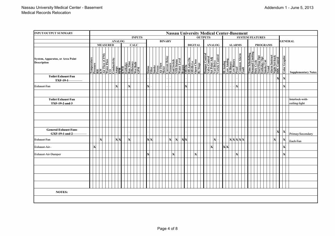
Nassau University Medical Center - Basement
Medical Records Relocation
Addendum 1 - June 5, 2013
INPUT/OUTPUT SUMMARY Nassau University Medical Center-BasementINPUTS OUTPUTS SYSTEM FEATURES
ANALOG BINARY GENERAL
MEASURED CALC DIGITAL ANALOG ALARMS PROGRAMS
System, Apparatus, or Area Point
Description
Tem
per
atu
reP
ress
ure
RH
KW
Air
Flo
w(C
FM
)W
ate
rF
low
CO
Co
nd
uct
ivit
yA
mp
sR
PM
KW
HE
nth
alp
yR
un
Tim
eE
ffic
ien
cyW
etB
ulb
GP
M
Sta
tus
Fil
ter
Sm
ok
eF
reez
eA
irF
low
Met
erC
urr
ent
Rel
ay
Pre
ssu
reE
nd
Sw
itch
VF
DS
tatu
sW
ate
rL
evel
By
pa
ssO
ff-O
nO
ff-A
uto
-On
Off
-Hi-
Lo
Op
en-C
lose
By
Sta
ge
Da
mp
erC
on
tro
lV
alv
eC
on
tro
lS
etP
oin
tA
dj
Va
riD
riv
eV
ort
ekC
on
tro
l
Hi
An
alo
gL
ow
An
alo
gH
iB
ina
ryL
ow
Bin
ary
Pro
of
Co
mm
on
Ala
rmF
au
lt
Tim
eS
ched
uli
ng
Dem
an
dL
imit
ing
Du
tyC
ycl
eS
tart
/Sto
pO
pt
En
tha
lpy
Op
tS
mo
ke
Cn
tT
ren
dA
larm
Inst
ruct
Nig
ht
Set
-ba
ckD
DC
Co
ntr
ol
Co
lor
Gra
ph
ic
Supplementary Notes
Toilet Exhaust Fan
TXF-19-1X X
Exhaust Fan X X X X X X
Toilet Exhaust Fan
TXF-19-2 and 3
Interlock with
ceiling light
General Exhaust Fans
GXF-19-1 and 2X X
Primay/Secondary
Exhaust Fan X X X X X X X X X X X X X X X X X X Each Fan
Exhaust Air X X X X X
Exhaust Air Damper X X X X X
NOTES:
Page 4 of 8

Nassau University Medical Center - Basement
Medical Records Relocation
Addendum 1 - June 5, 2013
INPUT/OUTPUT SUMMARY Nassau University Medical Center-BasementINPUTS OUTPUTS SYSTEM FEATURES
ANALOG BINARY GENERAL
MEASURED CALC DIGITAL ANALOG ALARMS PROGRAMS
System, Apparatus, or Area Point
Description
Tem
per
atu
reP
ress
ure
RH
KW
Air
Flo
w(C
FM
)W
ate
rF
low
CO
Co
nd
uct
ivit
yA
mp
sR
PM
KW
HE
nth
alp
yR
un
Tim
eE
ffic
ien
cyW
etB
ulb
GP
M
Sta
tus
Fil
ter
Sm
ok
eF
reez
eA
irF
low
Met
erC
urr
ent
Rel
ay
Pre
ssu
reE
nd
Sw
itch
VF
DS
tatu
sW
ate
rL
evel
By
pa
ssO
ff-O
nO
ff-A
uto
-On
Off
-Hi-
Lo
Op
en-C
lose
By
Sta
ge
Da
mp
erC
on
tro
lV
alv
eC
on
tro
lS
etP
oin
tA
dj
Va
riD
riv
eV
ort
ekC
on
tro
l
Hi
An
alo
gL
ow
An
alo
gH
iB
ina
ryL
ow
Bin
ary
Pro
of
Co
mm
on
Ala
rmF
au
lt
Tim
eS
ched
uli
ng
Dem
an
dL
imit
ing
Du
tyC
ycl
eS
tart
/Sto
pO
pt
En
tha
lpy
Op
tS
mo
ke
Cn
tT
ren
dA
larm
Inst
ruct
Nig
ht
Set
-ba
ckD
DC
Co
ntr
ol
Co
lor
Gra
ph
ic
Supplementary Notes
Air Cooled Split AC Unit
ACC-R-1 and 2X X X A
Supply Fan X X X X X X
Space X X X X
Misc X X X
NOTES: A - BMS contractor to furnish and install devices for control and monitoring as listed.
Page 5 of 8

Nassau University Medical Center - Basement
Medical Records Relocation
Addendum 1 - June 5, 2013
INPUT/OUTPUT SUMMARY Nassau University Medical Center-BasementINPUTS OUTPUTS SYSTEM FEATURES
ANALOG BINARY GENERAL
MEASURED CALC DIGITAL ANALOG ALARMS PROGRAMS
System, Apparatus, or Area Point
Description
Tem
per
atu
reP
ress
ure
RH
KW
Air
Flo
w(C
FM
)W
ate
rF
low
CO
Co
nd
uct
ivit
yA
mp
sR
PM
Da
mp
erP
osi
tio
nK
WH
En
tha
lpy
Ru
nT
ime
Eff
icie
ncy
Wet
Bu
lbG
PM
Sta
tus
Fil
ter
Sm
ok
eF
reez
eA
irF
low
Met
erC
urr
ent
Rel
ay
Pre
ssu
reE
nd
Sw
itch
VF
DS
tatu
sW
ate
rL
evel
By
pa
ssO
ff-O
nO
ff-A
uto
-On
Off
-Hi-
Lo
Op
en-C
lose
By
Sta
ge
Da
mp
erC
on
tro
lV
alv
eC
on
tro
lS
etP
oin
tA
dj
Va
riD
riv
eS
CR
Co
ntr
ol
Hi
An
alo
gL
ow
An
alo
gH
iB
ina
ryL
ow
Bin
ary
Pro
of
Co
mm
on
Ala
rmF
au
lt
Tim
eS
ched
uli
ng
Dem
an
dL
imit
ing
Du
tyC
ycl
eS
tart
/Sto
pO
pt
En
tha
lpy
Op
tS
mo
ke
Cn
tT
ren
dA
larm
Inst
ruct
Nig
ht
Set
-ba
ckD
DC
Co
ntr
ol
Co
lor
Gra
ph
ic
Supplementary Notes
Condensate Return Unit X X
Perimer Radiation/Cabinet Convector
Space X
Heating Valve X
NOTES:
Page 6 of 8

Nassau University Medical Center - Basement
Medical Records Relocation
Addendum 1 - June 5, 2013
INPUT/OUTPUT SUMMARY Nassau University Medical Center-BasementINPUTS OUTPUTS SYSTEM FEATURES
ANALOG BINARY GENERAL
MEASURED CALC DIGITAL ANALOG ALARMS PROGRAMS
System, Apparatus, or Area Point
Description
Tem
per
atu
reP
ress
ure
RH
KW
Air
Flo
w(C
FM
)W
ate
rF
low
CO
Co
nd
uct
ivit
yA
mp
sR
PM
Da
mp
erP
osi
tio
nK
WH
En
tha
lpy
Ru
nT
ime
Eff
icie
ncy
Wet
Bu
lbG
PM
Sta
tus
Fil
ter
Sm
ok
eF
reez
eA
irF
low
Met
erC
urr
ent
Rel
ay
Pre
ssu
reE
nd
Sw
itch
VF
DS
tatu
sW
ate
rL
evel
By
pa
ssO
ff-O
nO
ff-A
uto
-On
Off
-Hi-
Lo
Op
en-C
lose
By
Sta
ge
Da
mp
erC
on
tro
lV
alv
eC
on
tro
lS
etP
oin
tA
dj
Va
riD
riv
eS
CR
Co
ntr
ol
Hi
An
alo
gL
ow
An
alo
gH
iB
ina
ryL
ow
Bin
ary
Pro
of
Co
mm
on
Ala
rmF
au
lt
Tim
eS
ched
uli
ng
Dem
an
dL
imit
ing
Du
tyC
ycl
eS
tart
/Sto
pO
pt
En
tha
lpy
Op
tS
mo
ke
Cn
tT
ren
dA
larm
Inst
ruct
Nig
ht
Set
-ba
ckD
DC
Co
ntr
ol
Co
lor
Gra
ph
ic
Supplementary Notes
FPTU Box X X X
Box Damper X X X
Air Flow X X X X X
Space X X X X X
Supply Fan X
FPTU Box with Reheat X X X
Box Damper X X X
Air Flow X X X X X
Space X X X X X
Supply Fan X X
Heating Coil X X X
NOTES:
Page 7 of 8

Nassau University Medical Center - Basement
Medical Records Relocation
Addendum 1 - June 5, 2013
Nassau University Medical Center-Basement
Page 8 of 8