introduction 8085 lecture 1
DESCRIPTION
intro to 8085TRANSCRIPT

Microprocessors & Interfacing 1
Chapter 1Introduction

Microprocessors & Interfacing 2
What is a Microprocessor?
• The word comes from the combination Micro and processor. – Processor means a device that processes
whatever. In this context processor means a device that processes numbers, specifically binary numbers, 0’s and 1’s.• To process means to manipulate. It is a general
term that describes all manipulation. Again in this content, it means to perform certain operations on the numbers that depend on the microprocessor’s design.
Microprocessors & Interfacing 3
What about micro?• Micro is a new addition.
– In the late 1960’s, processors were built using discrete elements.
• These devices performed the required operation, but were too large and too slow.
– In the early 1970’s the microchip was invented. All of the components that made up the processor were now placed on a single piece of silicon.
– The size became several thousand times smaller and the speed became several hundred times faster. The “Micro”Processor was born.
Microprocessors & Interfacing 4
Was there ever a “mini”-processor?• No.
– It went directly from discrete elements to a single chip. However, comparing today’s microprocessors to the ones built in the early 1970’s you find an extreme increase in the amount of integration.
• So, What is a microprocessor? • -It is a programmable integrated device that has
decision making capability similar to that of the central processing unit (CPU).
Microprocessors & Interfacing 5
Definition of the Microprocessor
The microprocessor is a multipurpose,clock-driven, register-based programmable device that takes in numbers, performs on them arithmetic or logical operations according to the program stored in memory and then produces other numbers as a result.
Microprocessors & Interfacing 6
Definition (Contd.)Expanding each of the underlined words:
– Programmable device: The microprocessor can perform different sets of operations on the data it receives depending on the sequence of instructions supplied in the given program.By changing the program, the microprocessor manipulates the data in different ways.
– Instructions: Each microprocessor is designed to execute a specific group of operations. This group of operations is called an instruction set. This instruction set defines what the microprocessor can and cannot do.

Microprocessors & Interfacing 7
Definition (Contd.)– Takes in: The data that the microprocessor
manipulates must come from somewhere. • It comes from what is called “input devices”. • These are devices that bring data into the system from
the outside world. • These represent devices such as a keyboard, a mouse,
switches, and the like.
Microprocessors & Interfacing 8
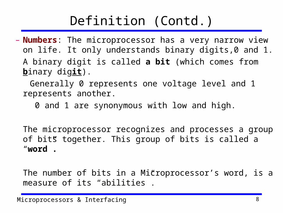
Definition (Contd.)– Numbers: The microprocessor has a very narrow view on
life. It only understands binary digits,0 and 1.A binary digit is called a bit (which comes from binary digit).
Generally 0 represents one voltage level and 1 represents another.
0 and 1 are synonymous with low and high.
The microprocessor recognizes and processes a group of bits together. This group of bits is called a “word”.
The number of bits in a Microprocessor’s word, is a measure of its “abilities”.

Microprocessors & Interfacing 9
Definition (Contd.)
– Words, Bytes, etc.• The earliest microprocessor (the Intel 8088 and Motorola’s 6800) recognized
8-bit words. – They processed information 8-bits at a time. That’s why they are called
“8-bit processors”. They can handle large numbers, but in order to process these numbers, they broke them into 8-bit pieces and processed each group of 8-bits separately.
• Later microprocessors (8086 and 68000) were designed with 16-bit words.– A group of 8-bits were referred to as a “half-word” or “byte”.– A group of 4 bits is called a “nibble”.– Also, 32 bit groups were given the name “long word”.
• Today, all processors manipulate at least 32 bits at a time and there exists microprocessors that can process 64, 80, 128 bits or more at a time.

Microprocessors & Interfacing 10
Definition (Contd.)– Arithmetic and Logic Operations:
• Every microprocessor has arithmetic operations such as add and subtract as part of its instruction set.
– Most microprocessors will have operations such as multiply and divide.
– Some of the newer ones will have complex operations such as square root.
• In addition, microprocessors have logic operations as well. Such as AND, OR, XOR, shift left, shift right, etc.
• Again, the number and types of operations define the microprocessor’s instruction set and depends on the specific microprocessor.

Microprocessors & Interfacing 11
Definition (Contd.)– Program: A program is a sequence of instructions
that bring data into the microprocessor, processes it and sends it out.
• There are many programming languages (C, C++, FORTRAN, and JAVA…) However, these programming languages can be grouped into three main levels .
• Machine language• Assembly language• High level Language
Microprocessors & Interfacing 12
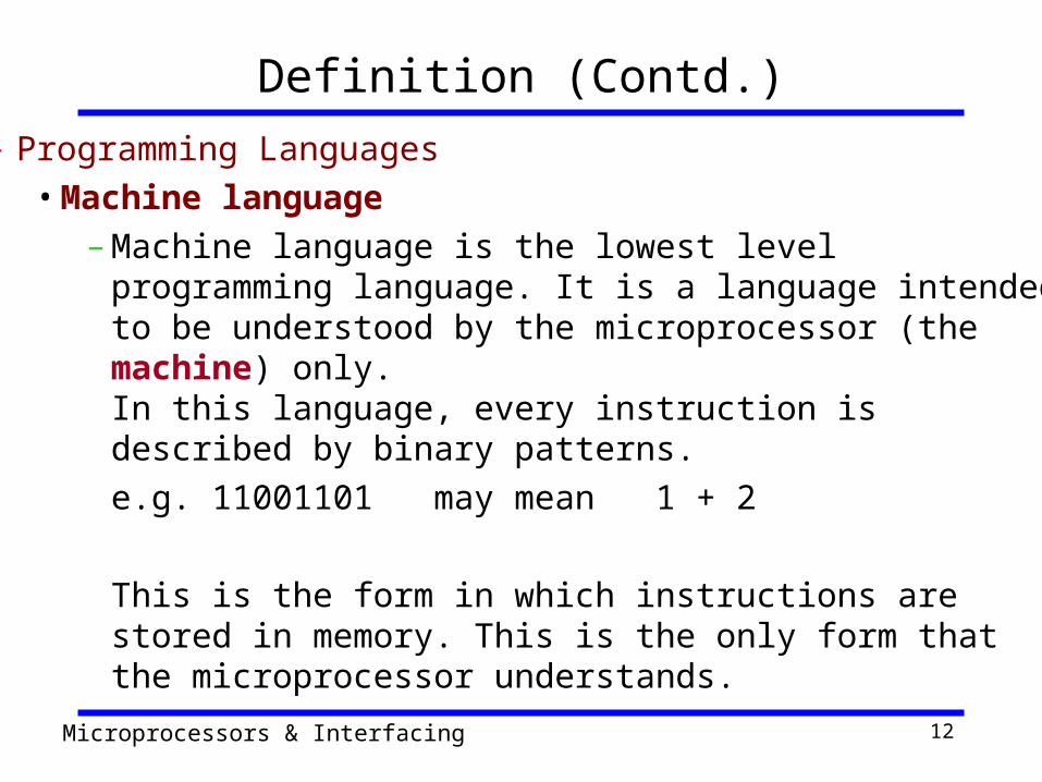
Definition (Contd.)– Programming Languages
• Machine language– Machine language is the lowest level programming language.
It is a language intended to be understood by the microprocessor (the machine) only.In this language, every instruction is described by binary patterns.e.g. 11001101 may mean 1 + 2
This is the form in which instructions are stored in memory. This is the only form that the microprocessor understands.
Microprocessors & Interfacing 13
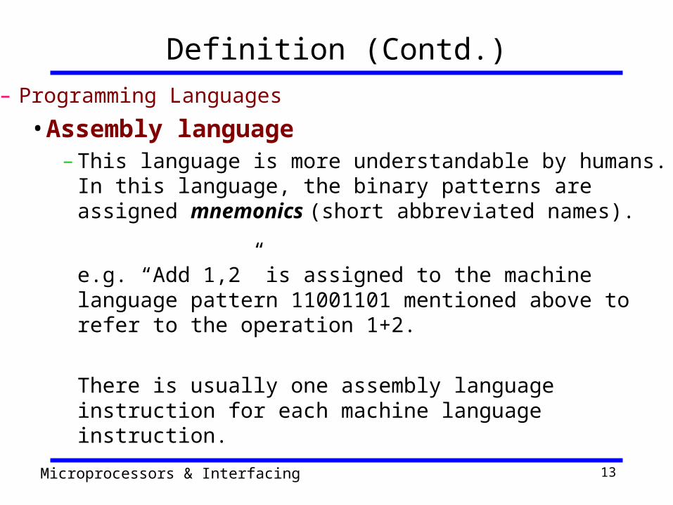
Definition (Contd.)– Programming Languages
• Assembly language– This language is more understandable by humans. In this
language, the binary patterns are assigned mnemonics (short abbreviated names).
e.g. “Add 1,2” is assigned to the machine language pattern 11001101 mentioned above to refer to the operation 1+2.
There is usually one assembly language instruction for each machine language instruction.
Microprocessors & Interfacing 14
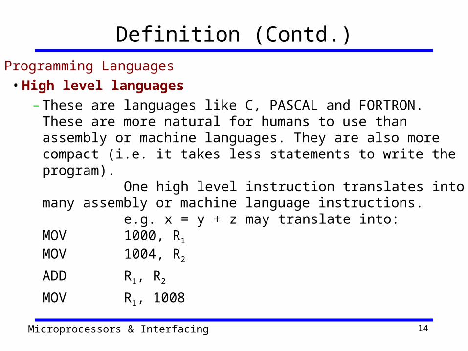
Definition (Contd.)– Programming Languages
• High level languages– These are languages like C, PASCAL and FORTRON. These
are more natural for humans to use than assembly or machine languages. They are also more compact (i.e. it takes less statements to write the program).
One high level instruction translates into many assembly or machine language instructions.
e.g. x = y + z may translate into:MOV 1000, R1
MOV 1004, R2
ADD R1, R2
MOV R1, 1008
Microprocessors & Interfacing 15
Definition (Contd.)– Programming Languages
• The new level being developed: is ultra high level languages which would contain things like C++, and JAVA.
– Here a single instruction may translate into hundreds of assembly or machine language instructions.

Microprocessors & Interfacing 16
Definition (Contd.) Stored in memory :
• First, what is memory?– Memory is the location where information is kept while not in current use. – It is like pages of a book with spaces for fixed no. of bits in each line.
However these pages are made of semiconductor material. – Memory is a collection of storage devices. Usually, each storage device
holds one bit. Also, in most kinds of memory, these storage devices are grouped into groups of 8. These 8 storage locations can only be accessed together. So, one can only read or write in terms of bytes to and form memory.
– Memory is usually measured by the number of bytes it can hold. It is measured in Kilos, Megas and lately Gigas.
– A Kilo in computer language is 210 =1024.– So, a KB (KiloByte) is 1024 bytes.– Mega is 1024 Kilos and Giga is 1024 Mega.

Microprocessors & Interfacing 17
Definition (Contd.)
–Stored in memory:• When a program is entered into a computer, it is
stored in memory. • Then as the microprocessor starts to execute the
instructions, it brings the instructions from memory one at a time.
• Memory is also used to hold the data.– The microprocessor reads (brings in) the data
from memory when it needs it and writes (stores) the results into memory when it is done.
Microprocessors & Interfacing 18
Definition (Contd.)– Produces: For the user to see the result of the
execution of the program, the results must be presented in a human readable form.
• The results must be presented on an output device.
• This can be the monitor, a paper from the printer, a simple LED or many other forms.
Microprocessors & Interfacing 19
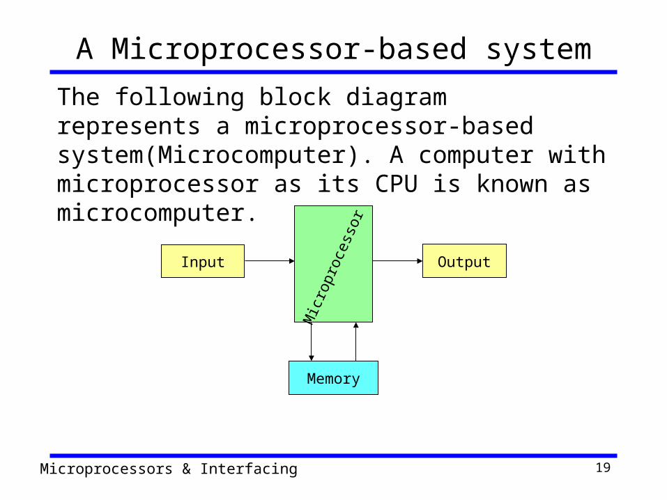
Memory
OutputInput
A Microprocessor-based systemThe following block diagram represents a microprocessor-based system(Microcomputer). A computer with microprocessor as its CPU is known as microcomputer.
Mic
ropr
oces
sor
Microprocessors & Interfacing 20
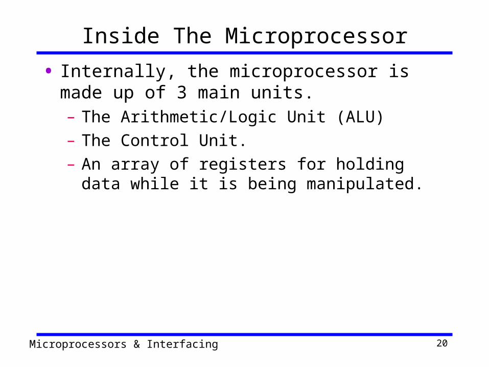
Inside The Microprocessor• Internally, the microprocessor is made up of 3
main units.– The Arithmetic/Logic Unit (ALU) – The Control Unit.– An array of registers for holding data while it is
being manipulated.

Microprocessors & Interfacing 21`1
Organization of a microprocessor-based system
I/OInput / Output
Memory
ROM RAM
System BusALU Register
Array
Control
• Let’s expand the picture a bit.

Microprocessors & Interfacing 22
Organization of the Microprocessor– The microprocessor can be divided into three main pieces:
• Arithmetic/Logic Unit– Performs all computing and logic operations such as addition and
subtraction as well as AND, OR and XOR.• Register Array
– A collection of registers within the microprocessor itself. These are used primarily for data storage during program execution. The number and the size of these registers differ from one microprocessor to the other.Usually regiters designated as letters B,C,D,E,H and L.
• Control Unit– As the name implies, the control Unit controls what is happening in
the microprocessor. It provides the necessary control and timing signals to all operations in the microprocessor as well as its contact to the outside world.
Microprocessors & Interfacing 23
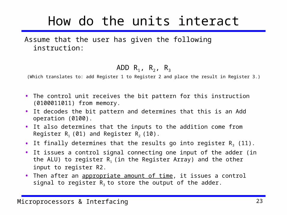
How do the units interactAssume that the user has given the following instruction:
ADD R1, R2, R3(Which translates to: add Register 1 to Register 2 and place the result in Register 3.)
• The control unit receives the bit pattern for this instruction (0100011011) from memory.
• It decodes the bit pattern and determines that this is an Add operation (0100).• It also determines that the inputs to the addition come from Register R1 (01)
and Register R2 (10).
• It finally determines that the results go into register R3 (11).
• It issues a control signal connecting one input of the adder (in the ALU) to register R1 (in the Register Array) and the other input to register R2.
• Then after an appropriate amount of time, it issues a control signal to register R3 to store the output of the adder.
Microprocessors & Interfacing 24
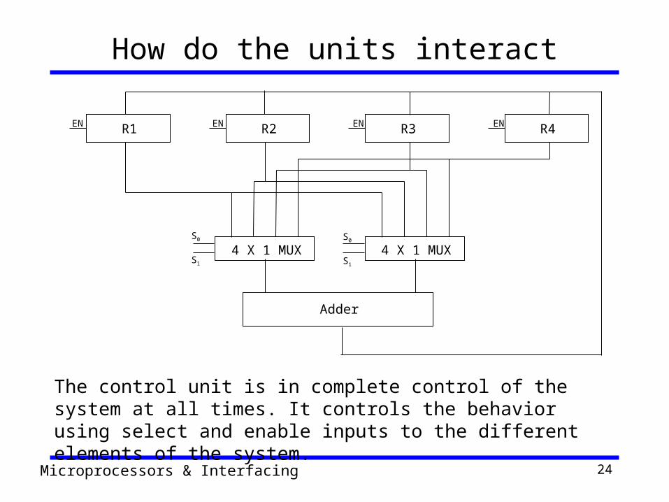
How do the units interact
The control unit is in complete control of the system at all times. It controls the behavior using select and enable inputs to the different elements of the system.
EN EN EN EN
S0
S1
S0
S1
Adder
4 X 1 MUX 4 X 1 MUX
R1 R2 R3 R4

Microprocessors & Interfacing 25
Memory• Memory stores information such as instructions and data
in binary format (0 and 1). It provides this information to the microprocessor whenever it is needed.
• Usually, there is a memory “sub-system” in a microprocessor-based system. This sub-system includes:– The registers inside the microprocessor – Read Only Memory (ROM)
• used to store information that does not change.– Random Access Memory (RAM) (also known as
Read/Write Memory).• used to store information supplied by the user. Such as
programs and data.

Microprocessors & Interfacing 26
Memory• To execute a program:
– the user enters its instructions in binary format into the memory.
– The microprocessor then reads these instructions and whatever data is needed from memory, executes the instructions and places the results either in memory or produces it on an output device.

Microprocessors & Interfacing 27
I/O Input/Output• Input and output devices are the system’s means
of communicating with the outside world. These devices are collectively known as peripherals.– Input devices transfer binary information from the
outside world to the microprocessor.• Examples of input devices are: keyboard,A/D convertors,
mouse, bar code reader, scanner and the like.
– Output devices transfer binary information from the microprocessor to the outside world.
• Theses include things like an LED,CRT or video screen, a monitor,X-Y plotter,D/A converter, a printer and the like.
Microprocessors & Interfacing 28
System Bus• A communication path between the
microprocessor and peripherals. – It is simply a group of wires carrying the voltages
and curents representing the different bit values.
• The microprocessor communicates with only one peripheral at a time.
• Controlling the bus is done by the Control Unit.
Microprocessors & Interfacing 29
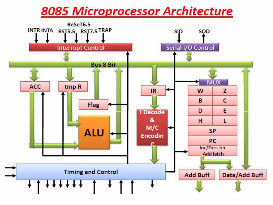
Microprocessor Architecture
Microprocessors & Interfacing 30
Microprocessors & Interfacing 31
Microprocessor Architecture• The microprocessor can be programmed to
perform functions on given data by writing specific instructions into its memory.– The microprocessor reads one instruction at a
time, matches it with its instruction set, and performs the data manipulation specified.
– The result is either stored back into memory or displayed on an output device.
Microprocessors & Interfacing 32

Microprocessors & Interfacing 33
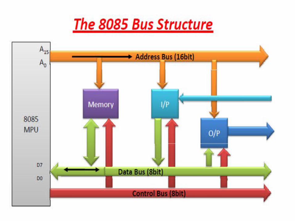
The 8085 Architecture• The 8085 uses three separate busses to perform
its operations– The address bus.– The data bus.– The control bus.
Microprocessors & Interfacing 34
Microprocessors & Interfacing 35
The Address Bus– 16 bits wide (A0 A1…A15)
• Therefore, the 8085 can access locations with numbers from 0 to 65,536. Or, the 8085 can access a total of 64K addresses.
– “Unidirectional”.• Information flows out of the microprocessor and into the
memory or peripherals.
– When the 8085 wants to access a peripheral or a memory location, it places the 16-bit address on the address bus and then sends the appropriate control signals.
Microprocessors & Interfacing 36
The Data Bus– 8 bits wide (D0 D1…D7)– “Bi-directional”.
• Information flows both ways between the microprocessor and memory or I/O.
– The 8085 uses the data bus to transfer the binary information.
– Since the data bus has 8-bits only, then the 8085 can manipulate data 8 bits at-a-time only.

Microprocessors & Interfacing 37
The Control Bus– There is no real control bus. Instead, the control
bus is made up of a number of single bit control signals.

Microprocessors & Interfacing 38

Microprocessors & Interfacing 39
Operation Types in a Microprocessor• All of the operations of the microprocessor can
be classified into one of three types:- Microprocessor Initiated Operations- Internal Operations- Peripheral Initiated Operations
Microprocessors & Interfacing 40
Microprocessor Initiated Operations• It is important to note that the microprocessor treats
memory and I/O devices the same way. – Input and output devices simply look like memory locations
to the microprocessor.• For example, the keyboard may look like memory
address A3F2H. To get what key is being pressed, the microprocessor simply reads the data at location A3F2H.
– The communication process between the microprocessor and peripheral devices consist of the following three steps:
– Identify the address.– Transfer the binary information.– Provide the right timing signals.

Microprocessors & Interfacing 41
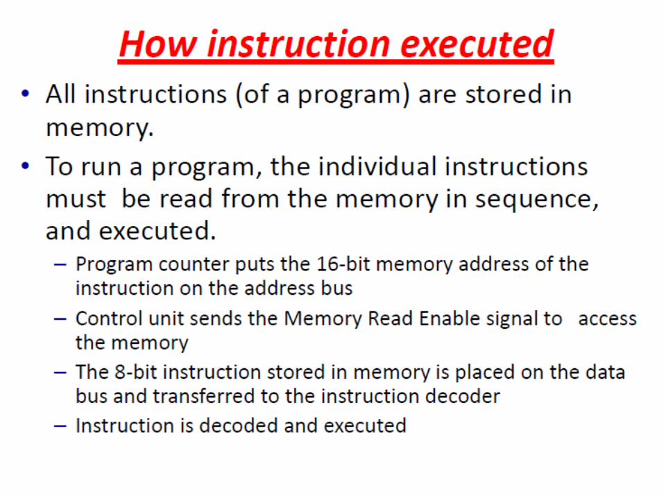
The Read Operation– To read the contents of a memory location, the
following steps take place:• The microprocessor places the 16-bit address of the
memory location on the address bus. • The microprocessor activates a control signal called
“memory read” which enables the memory chip.• The memory decodes the address and identifies the
right location. • The memory places the contents on the data bus. • The microprocessor reads the value of the data bus after
a certain amount of time.
Microprocessors & Interfacing 42
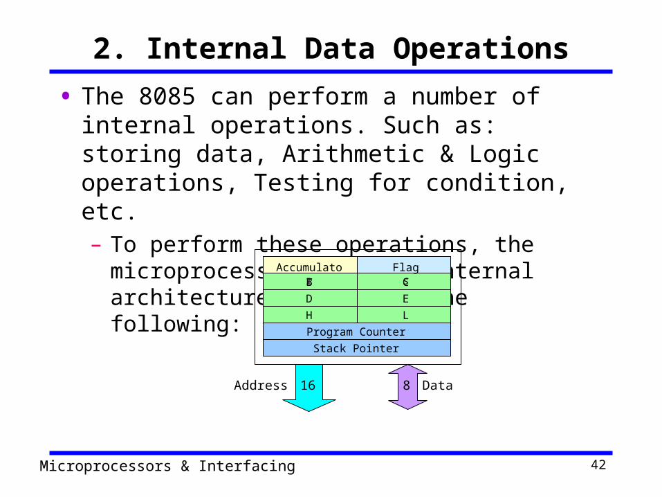
2. Internal Data Operations• The 8085 can perform a number of internal
operations. Such as: storing data, Arithmetic & Logic operations, Testing for condition, etc.– To perform these operations, the microprocessor
needs an internal architecture similar to the following:
Accumulator FlagsB CD EH L
Program CounterStack Pointer
DataAddress 816

Microprocessors & Interfacing 43
The Internal Architecture• We have already discussed the general purpose
registers, the Accumulator, and the flags.
• The Program Counter (PC)– This is a register that is used to control the
sequencing of the execution of instructions.– This register always holds the address of the next
instruction.– Since it holds an address, it must be 16 bits wide.
Microprocessors & Interfacing 44
The Internal Architecture• The Stack pointer
– The stack pointer is also a 16-bit register that is used to point into memory.
– The memory this register points to is a special area called the stack.
– The stack is an area of memory used to hold data that will be retreived soon.
– The stack is usually accessed in a Last In First Out (LIFO) fashion.
Microprocessors & Interfacing 45
3. Externally Initiated Operations• External devices can initiate (start) one of the 4
following operations:– Reset
• All operations are stopped and the program counter is reset to 0000.
– Interrupt• The microprocessor’s operations are interrupted and the
microprocessor executes what is called a “service routine”.
• This routine “handles” the interrupt, (perform the necessary operations). Then the microprocessor returns to its previous operations and continues.

Microprocessors & Interfacing 46
Externally Initiated Operations– Ready
• The 8085 has a pin called RDY. This pin is used by external devices to stop the 8085 until they catch up.
• As long as the RDY pin is low, the 8085 will be in a wait state.
– Hold• The 8085 has a pin called HOLD. This pin is used by
external devices to gain control of the busses.• When the HOLD signal is activated by an external
device, the 8085 stops executing instructions and stops using the busses.
• This would allow external devices to control the information on the busses. Example DMA.
Microprocessors & Interfacing 47
The three cycle instruction execution model
• To execute a program, the microprocessor “reads” each instruction from memory, “interprets” it, then “executes” it.
• To use the right names for the cycles:– The microprocessor fetches each instruction,– decodes it,– Then executes it.
• This sequence is continued until all instructions are performed.

Microprocessors & Interfacing 48
Machine Language• The number of bits that form the “word” of a
microprocessor is fixed for that particular processor. – These bits define a maximum number of combinations.
• For example an 8-bit microprocessor can have at most 28 = 256 different combinations.
• However, in most microprocessors, not all of these combinations are used. – Certain patterns are chosen and assigned specific
meanings. – Each of these patterns forms an instruction for the
microprocessor. – The complete set of patterns makes up the
microprocessor’s machine language.
Microprocessors & Interfacing 49
The 8085 Machine Language• The 8085 (from Intel) is an 8-bit microprocessor.
– The 8085 uses a total of 246 bit patterns to form its instruction set.
– These 246 patterns represent only 74 instructions. • The reason for the difference is that some (actually most)
instructions have multiple different formats.
– Because it is very difficult to enter the bit patterns correctly, they are usually entered in hexadecimal instead of binary.
• For example, the combination 0011 1100 which translates into “increment the number in the register called the accumulator”, is usually entered as 3C.

Microprocessors & Interfacing 50
Assembly Language• Entering the instructions using hexadecimal is quite
easier than entering the binary combinations. – However, it still is difficult to understand what a
program written in hexadecimal does.– So, each company defines a symbolic code for the
instructions.– These codes are called “mnemonics”.– The mnemonic for each instruction is usually a group
of letters that suggest the operation performed.
Microprocessors & Interfacing 51
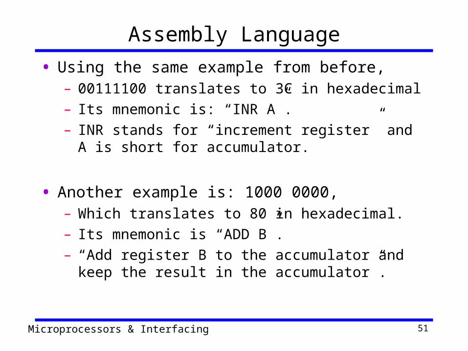
Assembly Language• Using the same example from before,
– 00111100 translates to 3C in hexadecimal – Its mnemonic is: “INR A”. – INR stands for “increment register” and A is short for
accumulator.
• Another example is: 1000 0000,– Which translates to 80 in hexadecimal. – Its mnemonic is “ADD B”. – “Add register B to the accumulator and keep the result
in the accumulator”.

Microprocessors & Interfacing 52
Assembly Language• It is important to remember that a machine
language and its associated assembly language are completely machine dependent.– In other words, they are not transferable from one
microprocessor to a different one.
• For example, Motorolla has an 8-bit microprocessor called the 6800.– The 8085 machine language is very different from
that of the 6800. So is the assembly language.– A program written for the 8085 cannot be executed
on the 6800 and vice versa.

Microprocessors & Interfacing 53
“Assembling” The Program• How does assembly language get translated into
machine language?– There are two ways: – 1st there is “hand assembly”.
• The programmer translates each assembly language instruction into its equivalent hexadecimal code (machine language). Then the hexadecimal code is entered into memory.
– The other possibility is a program called an “assembler”, which does the translation automatically.
Microprocessors & Interfacing 54
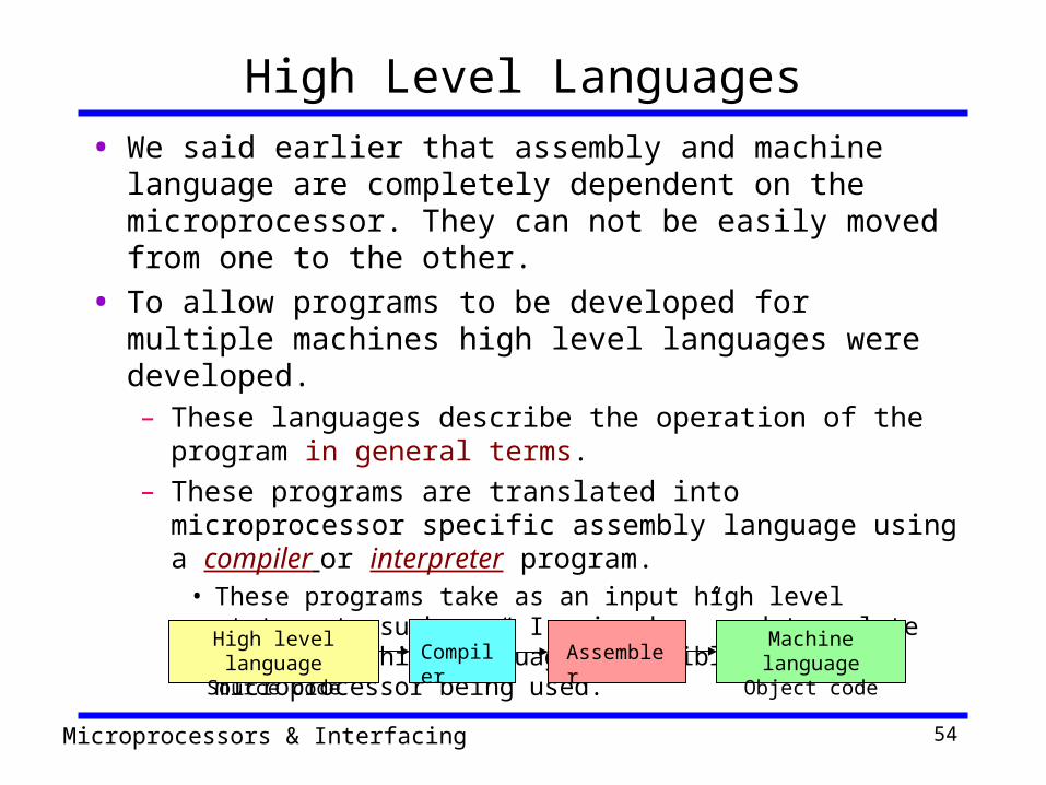
High Level Languages• We said earlier that assembly and machine language are
completely dependent on the microprocessor. They can not be easily moved from one to the other.
• To allow programs to be developed for multiple machines high level languages were developed. – These languages describe the operation of the program in
general terms.– These programs are translated into microprocessor specific
assembly language using a compiler or interpreter program. • These programs take as an input high level statements such as
“ I = j + k; ” and translate them to machine language compatible with the microprocessor being used.
High level languageSource code
Machine languageObject codeCompiler Assembler

Microprocessors & Interfacing 55
Compiler vs. Interpreter• What is the difference between Compiler and Interpreter?
– A compiler translates the entire program at once and produces the object code.
– An interpreter “ compiles “ the source code one line at-a-time. The object code for each line is produced, executed, and forgotten. Each time the program is to be executed, it has to be re-interpreted.
• Interpreters are very inefficient. Compilers produce object code that is quite a bit smaller and faster to execute.
• Compilers are still inefficient when complete control is needed and when memory is very critical.
• In such a situation, it is better to do the job yourself. – Writing a program in assembly language may not be easy. But,
you can control exactly how things are being done and which instruction is being used to perform each operation.
Microprocessors & Interfacing 56
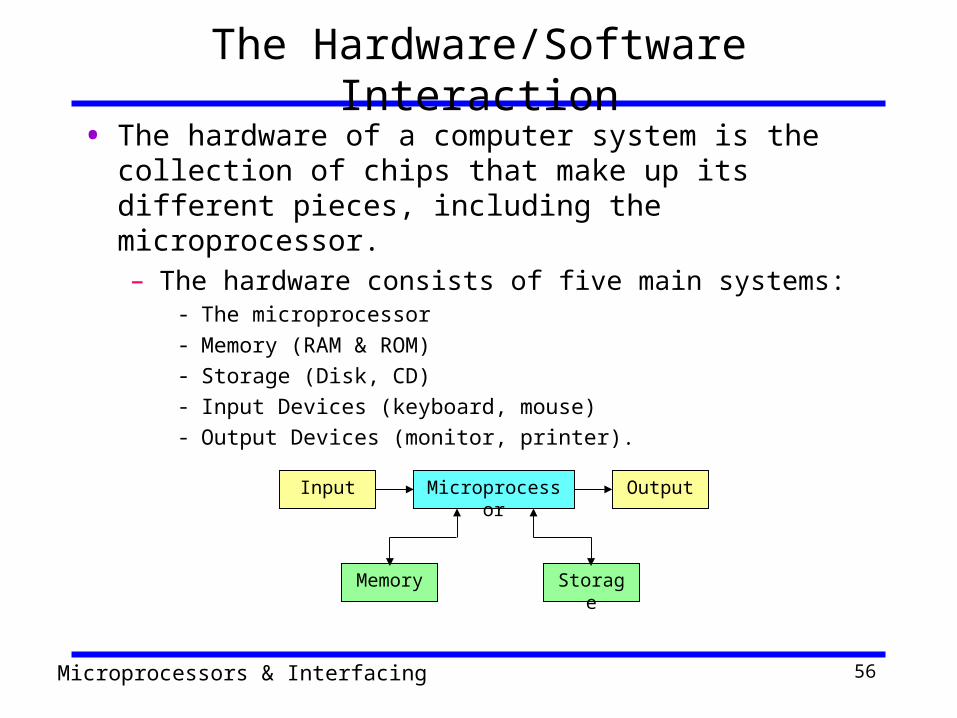
The Hardware/Software Interaction• The hardware of a computer system is the collection of
chips that make up its different pieces, including the microprocessor.– The hardware consists of five main systems:
- The microprocessor- Memory (RAM & ROM)- Storage (Disk, CD)- Input Devices (keyboard, mouse)- Output Devices (monitor, printer).
Input Microprocessor Output
Memory Storage

Microprocessors & Interfacing 57
The Hardware/Software interaction• Software refers to any program that executes on
the hardware.– It contains very low level programs that control the
behavior of the hardware all the way to complicated applications like 3D graphics, video editing, and circuit simulation and design.
• The interaction between the two systems (hardware and software) is managed by a group of programs known collectively as Operating system.

Microprocessors & Interfacing 58
The Operating System• The operating system is a layer between the application
programs and the hardware.– Pieces of the operating system control the operation of the
disks, the monitor, the keyboard, the mouse, the printer, the sound card, and even memory.
• When a program wants to use one of these items, it sends a request to the operating system and the operating system in turn will perform the operation.
• When the computer is first turned on, the operating system starts to execute. It stays running as long as the computer is operating.
Microprocessors & Interfacing 59
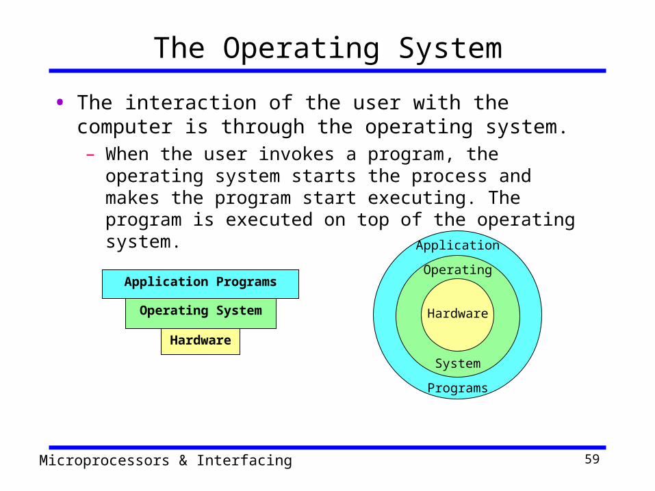
The Operating System
• The interaction of the user with the computer is through the operating system.– When the user invokes a program, the operating system
starts the process and makes the program start executing. The program is executed on top of the operating system.
Application Programs
Operating System
Hardware
Hardware
Operating
System
Application
Programs

Microprocessors & Interfacing 60
Operating Systems• Examples of operating systems are:
– MS-DOS– MS Windows– Macintosh OS– OS/2– UNIX
• Most operating systems are hardware specific:– For example, windows only runs on
microprocessors made by Intel or those that behave the same way (i.e. “compatible”).
• Other operating systems (like UNIX) are designed to work on any platform (hardware).