introduction 2 part 1 general information 3 part 2 indoor ... · mcac-ktsm-2011-06 cassette type...
TRANSCRIPT

MCAC-KTSM-2011-06 Cassette Type FCU
Introduction ........................................................................... 2
Part 1 General Information ................................................... 3
Part 2 Indoor Units ................................................................ 8
Part 3 Installation ................................................................ 54
Part 4 Controller .................................................................. 81

Cassette Type FCU MCAC-KTSM-2011-06
2 Introduction
Introduction Fan coil unit is a kind of compound device which assemble fan and surface-type coil heating-exchanger together. Fan coil with fresh air supply system is a main type of center air-conditioner system, so it is an important component of AC devices. Fan coil has horizontal type, vertical type, etc. A cooling (heating) supply system usually consists of fan coil terminals and chilled water system (heated water system).
Midea® commercial AC fan coil is designed and manufactured on the base of advanced technology, and utilize qualified galvanized iron as material. Due to its supper-thin design, it has such advantages: beautiful outlook, space saving, easy installation, etc. And the most obvious advantage is that it can decrease the outlet air Temp-difference as low as possible to make room more comfortable, as well as don’t decrease cooling capacity output. For the large air flow volume design, it can increase room ventilation frequency, supply more flesh air, and balance room temperature distribution. Benefiting from adoption of advanced material and technology, it can effectively decrease the running noise and keep running smoothly. With the advantages above, it can be widely applied in market, hospital, office building, hotel airport, etc.

MCAC-KTSM-2011-06 Cassette Type FCU
General Information 3
Part 1 General Information
Product Schedule ................................................................. 4
External Appearance ............................................................ 5
Nomenclature ........................................................................ 6
Features ................................................................................. 7

Cassette Type FCU MCAC-KTSM-2011-06
4 Product Schedule
Product Schedule No Type
Auxiliary Electrical Heater
Model Power source
1
Compact Four-way Cassette Type
Without
MKD-300
220-240V~,1Ph, 50Hz
2 MKD-400
3 MKD-500
4 MKD-300S
5 MKD-400S
6 MKD-500S
7
Four-way Cassette Type
Without
MKA-600R
8 MKA-750R
9 MKA-850R
10 MKA-950R
11 MKA-1200R
MKA-1500R
12
With
MKA-600RA
13 MKA-750RA
14 MKA-850RA
15 MKA-950RA
16 MKA-1200RA
17
One-way Cassette Type
Without MKC-300R
18 MKC-400R
19 With
MKC-300RA
20 MKC-400RA

MCAC-KTSM-2011-06 Cassette Type FCU
External Appearance 5
External Appearance Four-way Cassette Type Compact Four-way Cassette Type(2-pipe)
Compact Four-way Cassette Type(4-pipe) One way Cassette Type

Cassette Type FCU MCAC-KTSM-2011-06
6 Nomenclature
Nomenclature
M K A – 600R A
Function Code
A With Electrical Heater
- Without Electrical Heater
R Remote Control
Nominal Air Volume (CFM)
Type Code
A Four-way Cassette
C One-way Cassette
G Wall-mounted
Chilled Water Fan Coil Unit
Midea
M K D – 500 S
Product Type
S Four-pipe Fan Coil
- Two-pipe Fan Coil
Nominal Air Volume (CFM)
Type Code
D Compact Four-way Cassette With
Electric Control Box Inside
Chilled Water Fan Coil Unit
Midea

MCAC-KTSM-2011-06 Cassette Type FCU
Features 7
Features Chilled water/Hot water (2 pipes) Low height for easy installation Low noise fan direct driven by single phase, 3 speed permanent split capacitor motor. Copper tube/aluminum fin coils Hydrophilic aluminum fin coils coated (optional) Unit constructed by electrostatic galvanized sheet, providing maximum protection against corrosion Heavy gauge zinc coated steel drainage pan with good insulation processing, avoiding sweating and
corrosion
Cassette Type FCU MCAC-KTSM-2011-06
8 Indoor Units
Part 2 Indoor Units
Four-way Cassette Type ....................................................... 9
Compact Four-way Cassette Type .................................... 25
One-way Cassette Type ...................................................... 40
MCAC-KTSM-2011-06 Cassette Type FCU
Four -way cassette type 9
Four-way Cassette Type
Features ............................................................................... 10
Specification ........................................................................ 12
Dimensions .......................................................................... 14
Service Spaces .................................................................... 15
Wiring Diagram .................................................................... 16
Capacity Tables ................................................................... 18
Sound Levels ....................................................................... 20
Exploded View ..................................................................... 21
Troubleshooting .................................................................. 24

Cassette Type FCU MCAC-KTSM-2011-06
10 Features
Features 1) Ultra thin machine body to easy installation and maintenance: 600~750CFM: 230mm, 850~1500CFM:
300mm.
2) Different color panels for choose: White、Gray、Blue、Black
3) Adding digital tube displaying on the display board. LED can display the Error Code to make the
malfunction checking easier.
4) Drainage pump can take up the condenser water to 750mm.
5) Protection grill is standard for safety maintenance.
MCAC-KTSM-2011-06 Cassette Type FCU
Features 11
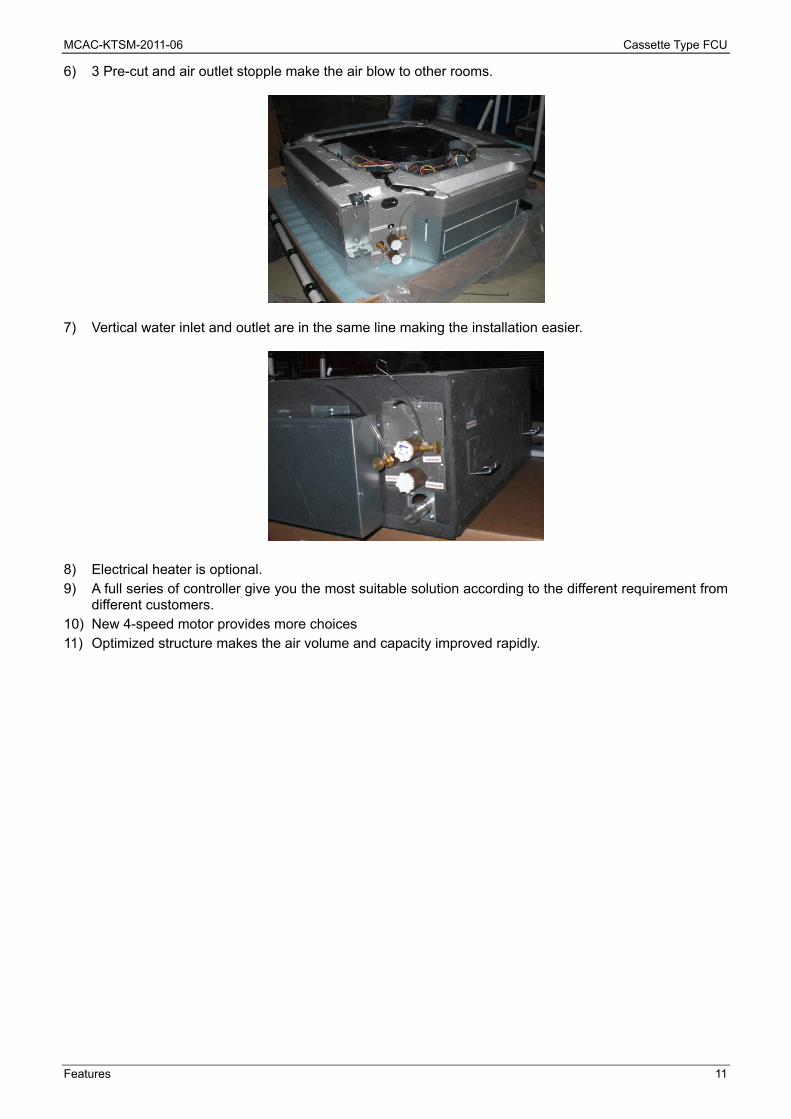
6) 3 Pre-cut and air outlet stopple make the air blow to other rooms.
7) Vertical water inlet and outlet are in the same line making the installation easier.
8) Electrical heater is optional. 9) A full series of controller give you the most suitable solution according to the different requirement from
different customers. 10) New 4-speed motor provides more choices 11) Optimized structure makes the air volume and capacity improved rapidly.

Cassette Type FCU MCAC-KTSM-2011-06
12 Specification
Specification Model No. MKA-600R(A) MKA-750R(A) MKA-850R(A)
Airflow
High
m3/h
1000 1250 1400
Medium 850 1060 1190
Low 720 900 1010
Cooling Capacity (Hi-speed) W 5700 7000 7270
Btu/h 19510 23840 24800
Heating Capacity (Hi-speed) W 9660 11550 12420
Btu/h 32970 39420 42360
Noise (Hi-speed) dB(A) 45 46 47
Water Flow l/min 16.4 20 20.8
Water Pressure Drop kPa 23.8 25.2 27
Indoor Coil
Number Of Rows 2
Tube Pitch(A)×Row Pitch(B) mm 21×13.37
Fin Spacing mm 1.5
Fin Type Hydrophilic aluminum
Tube Outside Dia. And Type mm φ7,bare tube
Coil dimension (L×H) mm 1960×168 1960×252
Number Of Circuits 8 12
Fan Motor
Type Low noise 4-speed fan motor
Number 1
Model YDK80-6E YDK90-6E
Input W 120 125 145
Capacitor uF 3uF/450V 3.5uF/450V 2.5uF/450V
Auxiliary Electrical Heater kW 2.1 2.1 2.85
Indoor Unit
Net Dimension (W×H×D) mm 840×230×840 840×300×840
Packing Dimension (W×H×D) mm 955×260×955 955×330×955
Net/Gross Weight (with EAH) kg 25/31(27/33) 30.5/37.2(33/40)
Panel
Net Dimension (W×H×D) mm 950×46×950
Packing Dimension (W×H×D) mm 1035×90×1035
Net/Gross Weight kg 6/9
Control Mode wired controller(optional), remote controller (standard)
Pipe
Water-Inlet Pipe RC3/4” internal thread
Water-Return Pipe RC3/4” internal thread
Condensation Water-Outlet Pipe EVA+LDPE 3/4” external thread
Remark: 1. All performance data above is based upon 0Pa external static pressure.
2. Cooling capacity test condition: air inlet Temp. : 27DB℃/19WB℃, water inlet Temp. 7℃, water Temp. difference 5℃.
3. Heating capacity test condition:
Air inlet Temp. 21DB℃, water inlet Temp. 60 DB℃
The volume of air and water is same as cooling.
4. Noise level is tested in full-anechoic room.
5. The auxiliary electrical heater is only available for MKA-XXXRA series.

MCAC-KTSM-2011-06 Cassette Type FCU
Specification 13
Model No. MKA-950R(A) MKA-1200R(A) MKA-1500R
Airflow
High
m3/h
1600 2000 2550
Medium 1360 1700 2170
Low 1150 1440 1840
Cooling Capacity (Hi-speed) W 8220 10390 12900
Btu/h 28050 35450 44010
Heating Capacity (Hi-speed) W 13850 17580 17600
Btu/h 47240 60000 60050
Noise (Hi-speed) dB(A) 48 49 50
Water Flow l/min 23.6 29.8 36.9
Water Pressure Drop kPa 31.2 44 40
Indoor Coil
Number Of Rows 2
Tube Pitch(A)×Row Pitch(B) mm 21×13.37
Fin Spacing mm 1.5
Fin Type Hydrophilic aluminum
Tube Outside Dia. And Type mm φ7,bare tube
Coil dimension (L×H) mm 1960×252 1960×252 2080×252
Number Of Circuits 12
Fan Motor
Type Low noise 4-speed fan motor
Number 1
Model YDK90-6E
Input W 150 185 185
Capacitor uF 3uF/450V 3.5uF/450V 3.5uF/450V
Auxiliary Electrical Heater kW 2.85
Indoor Unit
Net Dimension (W×H×D) mm 840×300×840
Packing Dimension (W×H×D) mm 955×330×955
Net/Gross Weight (with EAH) kg 30.5/37.2(33/40) 35/42
Panel
Net Dimension (W×H×D) mm 950×46×950
Packing Dimension (W×H×D) mm 1035×90×1035
Net/Gross Weight kg 6/9
Control Mode wired controller(optional), remote controller (standard)
Pipe
Water-Inlet Pipe RC3/4” internal thread
Water-Return Pipe RC3/4” internal thread
Condensation Water-Outlet Pipe EVA+LDPE 3/4” external thread
Remark:
1. All performance data above is based upon 0Pa external static pressure.
2. Cooling capacity test condition: air inlet Temp. : 27DB℃/19WB℃, water inlet Temp. 7℃, water Temp. difference 5℃.
3. Heating capacity test condition: Air inlet Temp. 21DB℃, water inlet Temp. 60 DB℃, the volume of air and water is same as cooling.
4. Noise level is tested in full-anechoic room.
5. The auxiliary electrical heater is only available for MKA-XXXRA series.
Cassette Type FCU MCAC-KTSM-2011-06
14 Dimensions
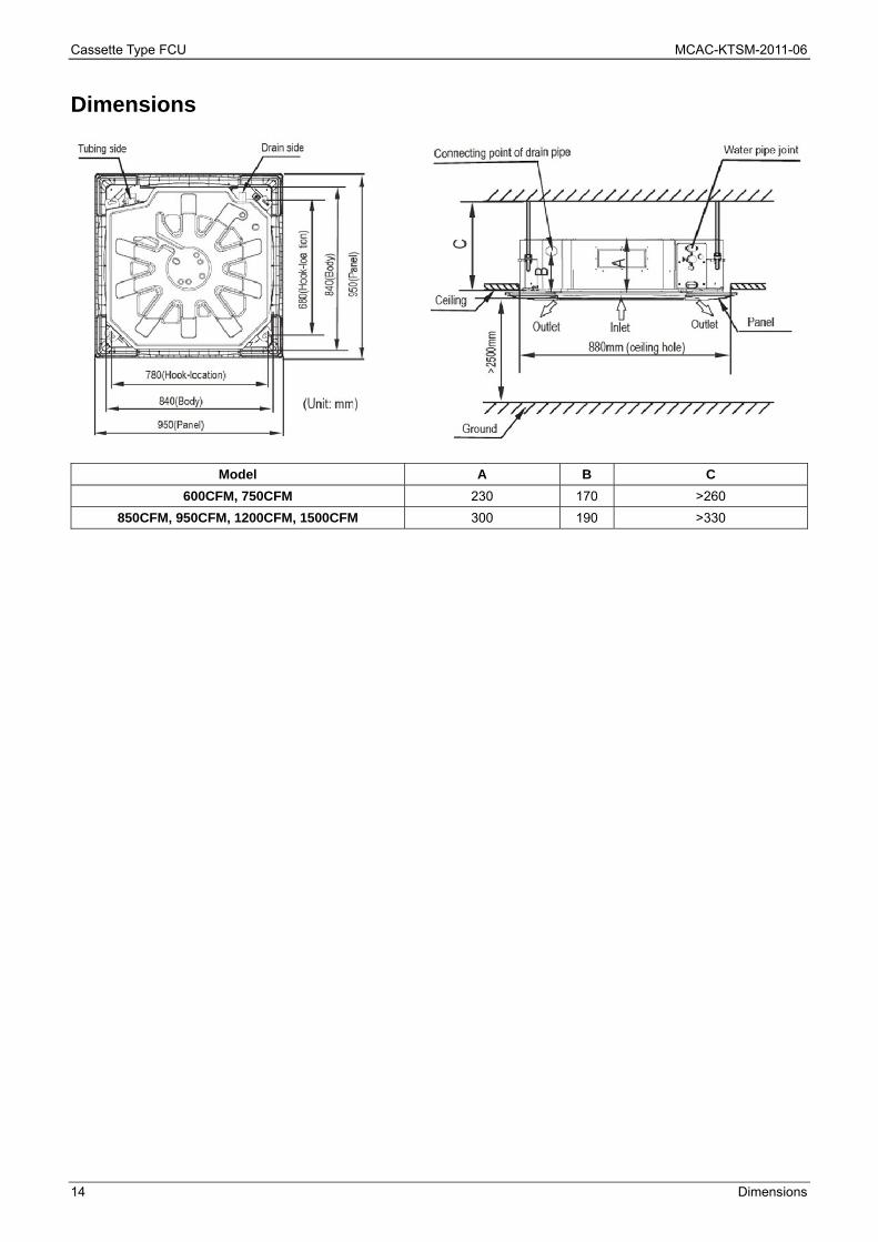
Dimensions
Model A B C
600CFM, 750CFM 230 170 >260
850CFM, 950CFM, 1200CFM, 1500CFM 300 190 >330
MCAC-KTSM-2011-06 Cassette Type FCU
Service Spaces 15
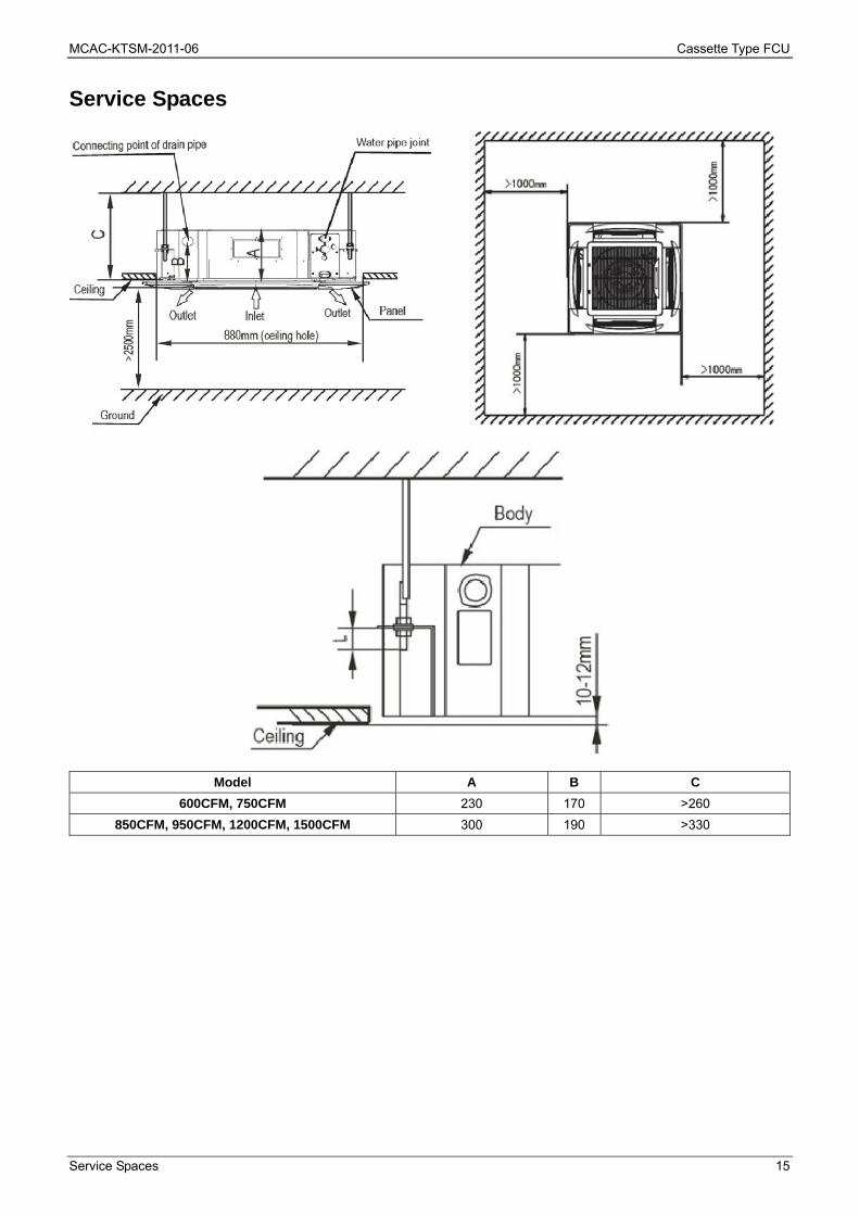
Service Spaces
Model A B C
600CFM, 750CFM 230 170 >260
850CFM, 950CFM, 1200CFM, 1500CFM 300 190 >330

Cassette Type FCU MCAC-KTSM-2011-06
16 Wiring Diagram
Wiring Diagram MKA-600R、MKA-750R、MKA-850R、MKA-950R、MKA-1200R、MKA-1500R

MCAC-KTSM-2011-06 Cassette Type FCU
Wiring Diagram 17
MKA-600RA、MKA-750RA、MKA-850RA、MKA-950RA、MKA-1200RA

Cassette Type FCU MCAC-KTSM-2011-06
18 Capacity Tables
Capacity Tables
Cooling Capacity:
Remark: DB: Dry Bulb Temp.; WB: Wet Bulb Temp.; EWT: Enter Water Temp.; LWT: Leaving Water Temp.; TC: Total Cooling Capacity; SC: Sensible Cooling Capacity;
Model Speed
Air On FCU Water Delta WaterTemp
Capacity Water Flow
Water Pressure
DropDB WB EWT LWT TC SC
℃ ℃ ℃ ℃ ℃ kW kW m3/h kPa
MKA-600R(A) High
26.7 19.4 7 12 5 5.63 4.7 16.2 25.37
5.5 14.5 9 3.1 2.59 8.2 12.68
27 19 7 12 5 5.7 4.81 16.4 23.8
5.5 14.5 9 2.93 2.69 7.7 11.9
29 21 7 12 5 7.2 5.4 20.7 32.43
5.5 14.5 9 3.96 2.97 10.3 16.22
MKA-750R(A) High
26.7 19.4 7 12 5 6.87 5.87 19.7 26.55
5.5 14.5 9 3.78 3.23 9.8 13.28
27 19 7 12 5 7 6.01 20 25.2
5.5 14.5 9 3.58 3.37 9.3 12.6
29 21 7 12 5 8.84 6.74 25.3 34.2
5.5 14.5 9 4.86 3.71 12.7 17.1
MKA-850R(A) High
26.7 19.4 7 12 5 7.14 5.94 20.5 28.63
5.5 14.5 9 3.93 3.27 10.3 14.31
27 19 7 12 5 7.27 6.07 20.8 27
5.5 14.5 9 3.72 3.39 9.7 13.5
29 21 7 12 5 9.13 6.81 26.2 36.54
5.5 14.5 9 5.02 3.75 13.2 18.27
MKA-950R(A) High
26.7 19.4 7 12 5 8.09 6.8 23.2 31.59
5.5 14.5 9 4.45 3.74 11.7 15.8
27 19 7 12 5 8.22 6.95 23.6 31.2
5.5 14.5 9 4.21 3.89 11.0 15
29 21 7 12 5 10.37 7.8 29.7 40.45
5.5 14.5 9 5.7 4.29 14.8 20.23
MKA-1200R(A) High
26.7 19.4 7 12 5 10.18 8.75 29.2 46.67
5.5 14.5 9 5.6 4.81 14.7 23.33
27 19 7 12 5 10.39 8.96 29.8 44
5.5 14.5 9 5.3 5.02 13.8 22
29 21 7 12 5 13.12 10.05 37.7 60.27
5.5 14.5 9 7.22 5.53 18.8 30.13
MKA-1500R High
26.7 19.4 7 12 5 12.63 11.11 36.2 48.69
5.5 14.5 9 6.95 6.11 18.2 24.35
27 19 7 12 5 12.9 11.37 36.9 40
5.5 14.5 9 6.57 6.37 17.2 23
29 21 7 12 5 16.36 12.76 46.8 63.05
5.5 14.5 9 9 7.02 23.5 31.53
Cooling capacity modification coefficient table:
Speed MKA-600R(A) MKA-750R(A) MKA-850R(A) MKA-950R(A) MKA-1200R(A) MKA-1500R
TC SC TC SC TC SC TC SC TC SC TC SC
Mid 0.92 0.88 0.92 0.88 0.93 0.89 0.92 0.88 0.93 0.89 0.94 0.9
Lo 0.85 0.81 0.84 0.8 0.85 0.81 0.84 0.81 0.84 0.8 0.85 0.81

MCAC-KTSM-2011-06 Cassette Type FCU
Capacity Tables 19
Heating Capacity: Remark: TH: Total Heating Capacity.
Model Speed
Water temp.
change
Air inlet temp. (21℃ DB)
Water inlet temp. (℃)
35 40 45 50 55 60 65 70
TH TH TH TH TH TH TH TH
℃ kW kW kW kW kW kW kW kW
MKA-600R(A) High
10 1.06 2.31 3.53 4.74 5.95 7.15 8.36 9.57
8 1.55 2.77 3.98 5.19 6.4 7.61 8.81 10.02
7 1.79 3 4.21 5.42 6.63 7.83 9.04 10.25
6 2.02 3.23 4.44 5.64 6.85 8.06 9.27 10.48
5 2.25 3.46 4.66 5.87 7.08 8.29 9.5 10.71
MKA-750R(A) High
10 1.22 2.7 4.16 5.61 7.06 8.51 9.96 11.42
8 1.81 3.27 4.72 6.17 7.62 9.07 10.53 11.98
7 2.1 3.55 5 6.45 7.9 9.36 10.81 12.27
6 2.38 3.83 5.28 6.73 8.19 9.64 11.1 12.55
5 2.66 4.11 5.56 7.02 8.47 9.93 11.39 12.85
MKA-850R(A) High
10 1.54 3.32 5.07 6.8 8.53 10.26 11.99 13.71
8 2.23 3.99 5.72 7.45 9.18 10.9 12.63 14.36
7 2.57 4.31 6.04 7.77 9.5 11.22 12.95 14.68
6 2.9 4.64 6.36 8.09 9.82 11.55 13.28 15.01
5 3.23 4.96 6.65 8.41 10.04 11.87 13.6 15.34
MKA-950R(A) High
10 1.65 3.6 5.51 7.41 9.3 11.2 13.09 14.98
8 2.41 4.33 6.23 8.12 10.02 11.91 13.81 15.7
7 2.79 4.69 6.59 8.48 10.37 12.27 14.17 16.06
6 3.15 5.05 6.94 8.84 10.73 12.63 14.53 16.43
5 3.51 5.41 7.3 9.2 10.09 12.99 14.89 16.8
MKA-1200R(A) High
10 1.91 4.24 6.54 8.84 11.13 13.42 15.72 18.01
8 2.83 5.15 7.44 9.73 12.02 14.32 16.62 18.92
7 3.29 5.59 7.88 10.18 12.47 14.77 17.07 19.37
6 3.74 6.04 8.11 10.63 12.92 15.22 17.53 19.83
5 4.19 9.48 8.78 11.08 13.38 15.68 17.99 20.3
MKA-1500R High
10 2.18 4.95 7.7 10.44 13.19 15.94 18.69 21.44
8 3.3 6.05 8.79 11.54 14.29 17.04 19.8 22.56
7 3.85 6.6 9.34 12.09 14.84 17.6 20.36 23.13
6 4.4 7.14 9.89 12.65 15.4 18.17 20.93 23.7
5 4.95 7.69 10.45 13.2 15.97 18.74 21.51 24.28
Cooling capacity modification coefficient table: Speed MKA-600R(A) MKA-750R(A) MKA-850R(A) MKA-950R(A) MKA-1200R(A) MKA-1500R
Mid 0.86 0.86 0.87 0.86 0.86 0.88
Lo 0.79 0.78 0.79 0.78 0.78 0.79

Cassette Type FCU MCAC-KTSM-2011-06
20 Sound Levels
Sound Levels TYPE MKA-600 R(A) MKA-750 R(A) MKA-850 R(A) MKA-950 R(A) MKA-1200 R(A) MKA-1500 R(A)
Noise dB(A) 45 46 47 48 49 50
FOUR-WAY CASSETTE TYPE
Microphone
1.0m
MCAC-KTSM-2011-06 Cassette Type FCU
Exploded View 21
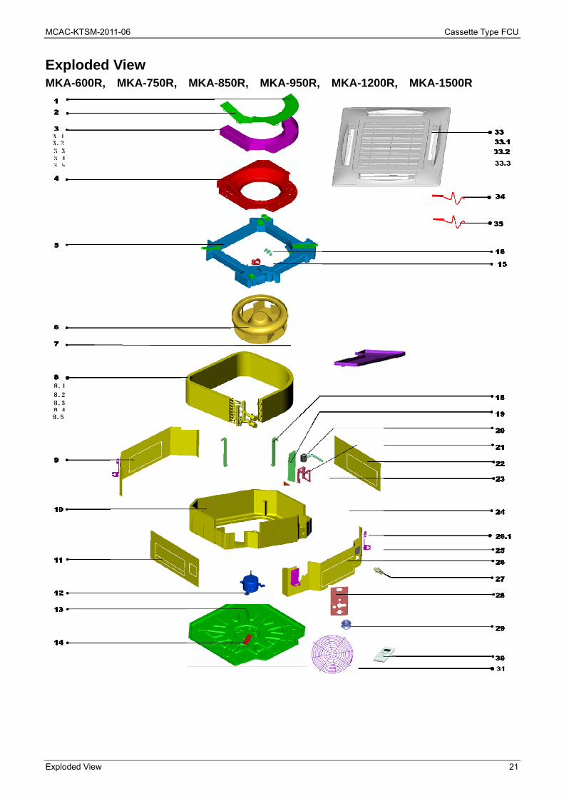
Exploded View MKA-600R, MKA-750R, MKA-850R, MKA-950R, MKA-1200R, MKA-1500R
Cassette Type FCU MCAC-KTSM-2011-06
22 Exploded View
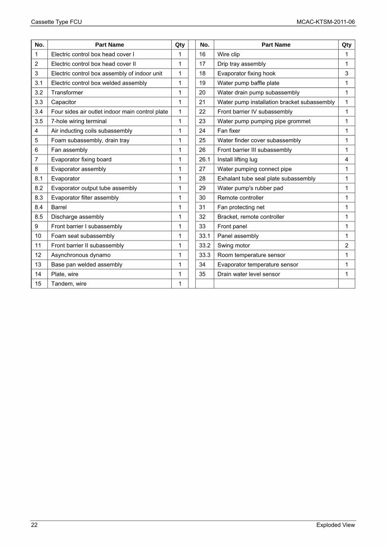
No. Part Name Qty No. Part Name Qty
1 Electric control box head cover I 1 16 Wire clip 1
2 Electric control box head cover II 1 17 Drip tray assembly 1
3 Electric control box assembly of indoor unit 1 18 Evaporator fixing hook 3
3.1 Electric control box welded assembly 1 19 Water pump baffle plate 1
3.2 Transformer 1 20 Water drain pump subassembly 1
3.3 Capacitor 1 21 Water pump installation bracket subassembly 1
3.4 Four sides air outlet indoor main control plate 1 22 Front barrier IV subassembly 1
3.5 7-hole wiring terminal 1 23 Water pump pumping pipe grommet 1
4 Air inducting coils subassembly 1 24 Fan fixer 1
5 Foam subassembly, drain tray 1 25 Water finder cover subassembly 1
6 Fan assembly 1 26 Front barrier III subassembly 1
7 Evaporator fixing board 1 26.1 Install lifting lug 4
8 Evaporator assembly 1 27 Water pumping connect pipe 1
8.1 Evaporator 1 28 Exhalant tube seal plate subassembly 1
8.2 Evaporator output tube assembly 1 29 Water pump's rubber pad 1
8.3 Evaporator filter assembly 1 30 Remote controller 1
8.4 Barrel 1 31 Fan protecting net 1
8.5 Discharge assembly 1 32 Bracket, remote controller 1
9 Front barrier I subassembly 1 33 Front panel 1
10 Foam seat subassembly 1 33.1 Panel assembly 1
11 Front barrier II subassembly 1 33.2 Swing motor 2
12 Asynchronous dynamo 1 33.3 Room temperature sensor 1
13 Base pan welded assembly 1 34 Evaporator temperature sensor 1
14 Plate, wire 1 35 Drain water level sensor 1
15 Tandem, wire 1
MCAC-KTSM-2011-06 Cassette Type FCU
Exploded View 23
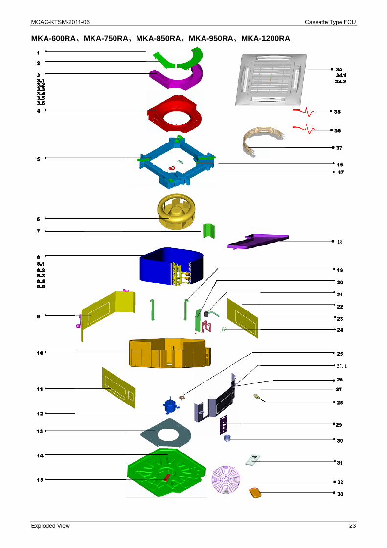
MKA-600RA、MKA-750RA、MKA-850RA、MKA-950RA、MKA-1200RA
Cassette Type FCU MCAC-KTSM-2011-06
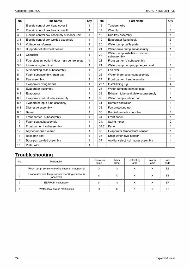
24 Exploded View
No Part Name Qty No Part Name Qty
1 Electric control box head cover I 1 16 Tandem, wire 1
2 Electric control box head cover II 1 17 Wire clip 1
3 Electric control box assembly of indoor unit 1 18 Drip tray assembly 1
3.1 Electric control box welded assembly 1 19 Evaporator fixing hook 3
3.2 Voltage transformer 1 20 Water pump baffle plate 1
3.3 Supporter of electrical heater 1 21 Water drain pump subassembly 1
3.4 Capacitor 1 22 Water pump installation bracket subassembly
1
3.5 Four sides air outlet indoor main control plate 1 23 Front barrier IV subassembly 1
3.6 7-hole wring terminal 1 24 Water pump pumping pipe grommet 1
4 Air inducting coils subassembly 1 25 Fan fixer 1
5 Foam subassembly, drain tray 1 26 Water finder cover subassembly 1
6 Fan assembly 1 27 Front barrier III subassembly 1
7 Evaporator fixing board 1 27.1 Install lifting lug 4
8 Evaporator assembly 1 28 Water pumping connect pipe 1
8.1 Evaporator 1 29 Exhalant tube seal plate subassembly 1
8.2 Evaporator output tube assembly 1 30 Water pump's rubber pad 1
8.3 Evaporator input tube assembly 1 31 Remote controller 1
8.4 Discharge assembly 1 32 Fan protecting net 1
8.5 Barrel 1 33 Bracket, remote controller 1
9 Front barrier I subassembly 1 34 Front panel 1
10 Foam seat subassembly 1 34.1 Swing motor 2
11 Front barrier II subassembly 1 34.2 Panel 1
12 Asynchronous dynamo 1 35 Evaporator temperature sensor 1
13 Base pan seat 1 36 Drain water level sensor 1
14 Base pan welded assembly 1 37 Auxiliary electrical heater assembly 1
15 Plate, wire 1
Troubleshooting
No. Malfunction Operation
lamp Timer lamp
Defrosting lamp
Alarm lamp
Error code
1 Room temp. sensor checking channel is abnormal X ☆ X X E2
2 Evaporator pipe temp. sensor checking channel is
abnormal ☆ X X X E3
3 EEPROM malfunction ☆ ☆ X X E7
4 Water-level switch malfunction X X X ☆ E8

MCAC-KTSM-2011-06 Cassette Type FCU
Compact Four-way Cassette Type 25
Compact Four-way Cassette Type
Features ............................................................................... 26
Specification ........................................................................ 27
Dimensions .......................................................................... 29
Wiring Diagram .................................................................... 30
Capacity Tables ................................................................... 34
Explored View ...................................................................... 38
Cassette Type FCU MCAC-KTSM-2011-06
26 Features
Features
Four-way air distribution gives individual comfort.
Electric control box is inside the body, which is convenient to maintain.
The unique design of the centrifugal fan ensures extra-quiet operation.
Four speeds indoor unit.
With the function of auto-restart.
High capacity of cooling / heating performance, high efficiency and energy-saving.
New panel.
MCAC-KTSM-2011-06 Cassette Type FCU
Specification 27
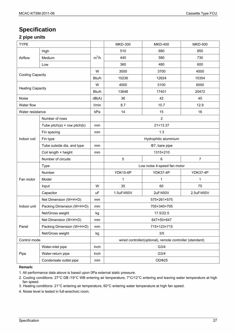
Specification 2 pipe units
TYPE MKD-300 MKD-400 MKD-500
Airflow
High
m3/h
510 680 850
Medium 440 580 730
Low 360 480 600
Cooling Capacity W 3000 3700 4500
Btu/h 10236 12624 15354
Heating Capacity W 4000 5100 6000
Btu/h 13648 17401 20472
Noise dB(A) 36 42 45
Water flow l/min 8.7 10.7 12.9
Water resistance kPa 14 15 16
Indoor coil
Number of rows 2
Tube pitch(a) × row pitch(b) mm 21×13.37
Fin spacing mm 1.3
Fin type Hydrophilic aluminium
Tube outside dia. and type mm Φ7, bare pipe
Coil length × height mm 1315×210
Number of circuits 5 6 7
Fan motor
Type Low noise 4-speed fan motor
Number YDK15-6P YDK37-4P YDK37-4P
Model 1 1 1
Input W 35 60 75
Capacitor uF 1.5uF/450V 2uF/450V 2.5uF/450V
Indoor unit
Net Dimension (W×H×D) mm 575×261×575
Packing Dimension (W×H×D) mm 705×340×705
Net/Gross weight kg 17.5/22.5
Panel
Net Dimension (W×H×D) mm 647×50×647
Packing Dimension (W×H×D) mm 715×123×715
Net/Gross weight kg 3/5
Control mode wired controller(optional), remote controller (standard)
Pipe
Water-inlet pipe Inch G3/4
Water-return pipe Inch G3/4
Condensate outlet pipe mm ODФ25
Remark:
1. All performance data above is based upon 0Pa external static pressure.
2. Cooling conditions: 27°C DB /19°C WB entering air temperature, 7°C/12°C entering and leaving water temperature at high fan speed.
3. Heating conditions: 21°C entering air temperature, 60°C entering water temperature at high fan speed.
4. Noise level is tested in full-anechoic room.

Cassette Type FCU MCAC-KTSM-2011-06
28 Specification
4 pipe units
Model MKD-300S MKD-400S MKD-500S
Air volume
High
m3/h
510 680 850
Medium 440 580 730
Low 360 480 600
Cooling capacity kW 2.5 2.9 3.5
Heating capacity kW 3.7 4.6 5.1
Sound level dB(A) 36 42 45
Cool water
Water flow l/min 7.2 8.4 10
Water pressure drop kPa 22 16 24
Heat water
Water flow l/min 8.7 12 16.4
Water pressure drop kPa 17 23 27
Fan Type Centrifugal fan
Quantity Pieces 1 1 1
Fan Motor
Model YDK15-6P YDK37-4P YDK37-4P
Quantity Pieces 1 1 1
Capacitor uF 1.5uF/450V 2uF/450V 2.5uF/450V
Input W 45 65 90
Coil
Number of rows 2
Tube pitch(a)x row pitch(b) mm 21×13.37
Fin spacing mm 1.3
Fin type (code) Hydrophilic aluminium
Tube outside dia. mm Φ7
Tube type bare pipe
Coil length × height mm 1315×210
Number of circuits 3 for cool water, 3 for
heat water 4 for cool water, 3 for heat water
Connection pipe
Cool water inlet/outlet Inch G3/4
Heat water inlet/outlet Inch G1/2
Drainage mm ODФ25
Body
Net dimension (W×H×D) mm 575×261×575
Packing dimension (W×H×D) mm 655×290×655
Net weight kg 17.5
Packing weight kg 22.5
Panel
Net dimension (W×H×D) mm 647×50×647
Packing dimension (W×H×D) mm 715×123×715
Net weight kg 3
Packing weight kg 5
Control wired controller(optional), remote controller (standard)
Remark: 1. All performance data above is based upon 0Pa external static pressure. 2. Cooling conditions: 27°C DB /19°C WB entering air temperature, 7°C/12°C entering and leaving water temperature at high
fan speed. 3. Heating conditions: 20°C entering air temperature, 70°C/60°C entering and leaving water temperature at high fan speed. 4. Noise level is tested in full-anechoic room.
MCAC-KTSM-2011-06 Cassette Type FCU
Dimensions 29
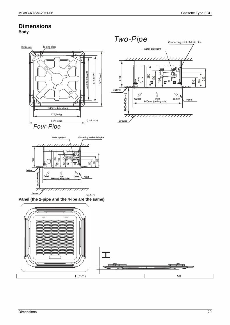
Dimensions Body
Panel (the 2-pipe and the 4-ipe are the same)
H(mm) 50

Cassette Type FCU MCAC-KTSM-2011-06
30 Wiring Diagram
Wiring Diagram MKD-300 MKD-400
MCAC-KTSM-2011-06 Cassette Type FCU
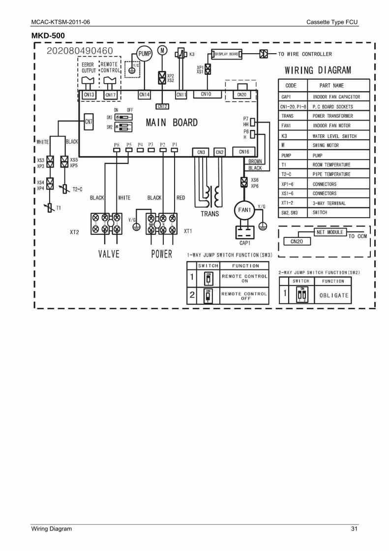
Wiring Diagram 31
MKD-500

Cassette Type FCU MCAC-KTSM-2011-06
32 Wiring Diagram
MKD-300S MKD-400S
MCAC-KTSM-2011-06 Cassette Type FCU
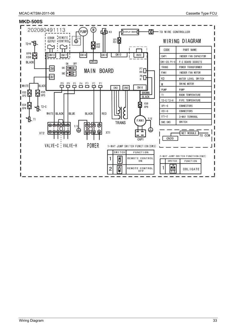
Wiring Diagram 33
MKD-500S

Cassette Type FCU MCAC-KTSM-2011-06
34 Capacity Tables
Capacity Tables 2-pipe units Cooling Capacity: Remark: DB: Dry Bulb Temp.; WB: Wet Bulb Temp.; EWT: Enter Water Temp.; LWT: Leaving Water Temp.; TC: Total Cooling Capacity; SC: Sensible Cooling Capacity;
Model Speed
Air On FCU Water Delta Water Temp.
Capacity Water Flow
Water Pressure
Drop DB WB EWT LWT TC SC
℃ ℃ ℃ ℃ ℃ kW kW l/min kPa
MKD-300 High
26.7 19.4 7 12 5 3.1 2.48 8.8 14.5
5.5 14.5 9 2.3 2.02 6.7 3
27 19 7 12 5 3 2.4 8.7 14
5.5 14.5 9 2.2 1.94 6.3 2.9
29 21 7 12 5 3.21 2.57 9.2 15
5.5 14.5 9 2.38 2.09 6.8 3.2
MKD-400 High
26.7 19.4 7 12 5 3.8 3.04 10.8 15.6
5.5 14.5 9 2.66 2.34 7.7 4.1
27 19 7 12 5 3.7 3 10.7 15
5.5 14.5 9 2.6 2.38 7.5 3.8
29 21 7 12 5 3.92 3.14 11.2 16
5.5 14.5 9 2.79 2.46 8.0 4
MKD-500 High
26.7 19.4 7 12 5 4.62 3.7 13.2 16.5
5.5 14.5 9 3.08 2.71 8.8 4.2
27 19 7 12 5 4.5 3.62 12.9 16
5.5 14.5 9 3 2.72 8.7 4
29 21 7 12 5 4.7 3.76 13.5 16.9
5.5 14.5 9 3.19 2.81 9.2 4.3
Cooling capacity modification coefficient table:
Speed MKD-300 MKD-400 MKD-500
TC SC TC SC TC SC
Mid 0.93 0.89 0.92 0.88 0.92 0.88
Lo 0.85 0.81 0.85 0.81 0.85 0.81

MCAC-KTSM-2011-06 Cassette Type FCU
Capacity Tables 35
Heating Capacity: Remark: TH: Total Heating Capacity.
Model Speed
Water temp.
change
Air inlet temp. (21℃ DB)
Water inlet temp. (℃)
35 40 45 50 55 60 65 70
TH TH TH TH TH TH TH TH
℃ kW kW kW kW kW kW kW kW
MKD-300 High
10 0.8 1.75 2.69 3.59 4.5 5.41 6.36 7.25
8 1.21 2.1 3.03 3.95 4.82 5.74 6.68 7.61
7 1.37 2.28 3.22 4.09 5 5.9 6.87 7.83
6 1.53 2.45 3.38 4.27 5.18 6.06 7.06 8.05
5 1.69 2.63 3.54 4.45 5.36 6.22 7.25 8.27
MKD-400 High
10 1.02 2.22 3.41 4.55 5.71 6.87 8.07 9.2
8 1.53 2.67 3.85 5.01 6.11 7.28 8.47 9.66
7 1.73 2.89 4.09 5.19 6.34 7.48 8.72 9.94
6 1.94 3.11 4.29 5.42 6.57 7.69 8.96 10.21
5 2.14 3.33 4.5 5.65 6.8 7.9 9.2 10.49
MKD-500 High
10 1.2 2.61 4 5.35 6.71 8.06 9.47 10.8
8 1.8 3.13 4.52 5.88 7.18 8.54 9.95 11.34
7 2.04 3.39 4.8 6.1 7.45 8.79 10.23 11.66
6 2.27 3.65 5.04 6.36 7.71 9.03 10.52 11.99
5 2.51 3.91 5.28 6.63 7.98 9.27 10.8 12.31
Heating capacity modification coefficient table: Model MKD-300 MKD-400 MKD-500
Mid-speed 0.87 0.86 0.86
Low-speed 0.79 0.79 0.79

Cassette Type FCU MCAC-KTSM-2011-06
36 Capacity Tables
4-pipe units Cooling Capacity: Remark: DB: Dry Bulb Temp.; WB: Wet Bulb Temp.; EWT: Enter Water Temp.; LWT: Leaving Water Temp.; TC: Total Cooling Capacity; SC: Sensible Cooling Capacity;
Model Speed
Air On FCU Water Delta Water Temp.
Capacity Water Flow
Water Pressure
Drop DB WB EWT LWT TC SC
℃ ℃ ℃ ℃ ℃ kW kW l/min kPa
MKD-300S High
26.7 19.4 7 12 5 2.6 2.2 7.5 22.6
5.5 14.5 9 1.75 1.68 5.0 4.9
27 19 7 12 5 2.5 2.1 7.2 22
5.5 14.5 9 1.7 1.62 4.8 4.5
29 21 7 12 5 2.74 2.25 7.8 23
5.5 14.5 9 1.88 1.75 5.3 5.1
MKD-400S High
26.7 19.4 7 12 5 3 2.4 8.7 16.5
5.5 14.5 9 2.15 1.98 6.2 9.4
27 19 7 12 5 2.9 2.3 8.4 16
5.5 14.5 9 2.1 1.92 6.0 9
29 21 7 12 5 3.12 2.48 9.0 17.1
5.5 14.5 9 2.2 2.14 6.3 9.7
MKD-500S High
26.7 19.4 7 12 5 3.58 2.95 10.3 24.6
5.5 14.5 9 2.6 2.3 7.5 6.4
27 19 7 12 5 3.5 2.9 10 24
5.5 14.5 9 2.5 2.25 7.2 6
29 21 7 12 5 3.74 3 10.7 25.2
5.5 14.5 9 2.68 2.45 7.7 6.9
Cooling capacity modification coefficient table:
Speed MKD-300 MKD-400 MKD-500
TC SC TC SC TC SC
Mid 0.93 0.89 0.92 0.88 0.92 0.88
Lo 0.85 0.81 0.85 0.81 0.85 0.81

MCAC-KTSM-2011-06 Cassette Type FCU
Capacity Tables 37
Heating Capacity: Remark: TH: Total Heating Capacity.
Model Speed
Water temp.
change
Air inlet temp. (20℃ DB)
Water inlet temp. (℃)
35 40 45 50 55 60 65 70
TH TH TH TH TH TH TH TH
℃ kW kW kW kW kW kW kW kW
MKD-300S High
10 0.41 0.89 1.37 1.83 2.3 2.76 3.25 3.7
8 0.62 1.07 1.55 2.01 2.46 2.93 3.41 3.89
7 0.7 1.16 1.64 2.09 2.55 3.01 3.51 4
6 0.78 1.25 1.73 2.18 2.64 3.09 3.6 4.11
5 0.86 1.34 1.81 2.27 2.73 3.18 3.7 4.22
MKD-400S High
10 0.51 1.11 1.7 2.28 2.86 3.43 4.04 4.6
8 0.76 1.33 1.93 2.5 3.06 3.64 4.24 4.83
7 0.87 1.44 2.04 2.6 3.17 3.74 4.36 4.97
6 0.97 1.56 2.15 2.71 3.29 3.84 4.48 5.11
5 1.07 1.67 2.25 2.82 3.4 3.95 4.6 5.24
MKD-500S High
10 0.57 1.23 1.89 2.52 3.17 3.81 4.47 5.1
8 0.85 1.48 2.13 2.78 3.39 4.03 4.7 5.36
7 0.96 1.6 2.27 2.88 3.52 4.15 4.83 5.51
6 1.07 1.72 2.38 3 3.64 4.26 4.97 5.66
5 1.19 1.85 2.49 3.13 3.77 4.38 5.1 5.81
Heating capacity modification coefficient table: Model MKD-300S MKD-400S MKD-500S
Mid-speed 0.87 0.86 0.86
Low-speed 0.79 0.79 0.79
Cassette Type FCU MCAC-KTSM-2011-06
38 Explored View
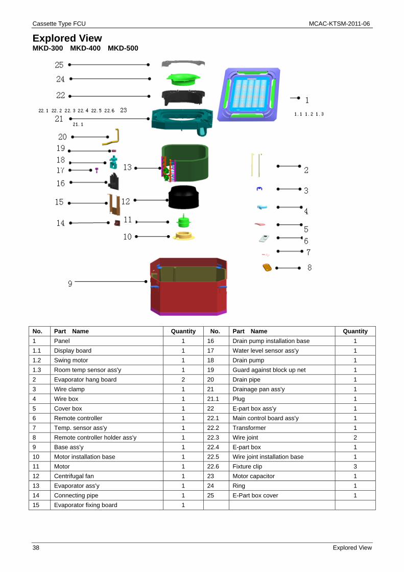
Explored View MKD-300 MKD-400 MKD-500
No. Part Name Quantity No. Part Name Quantity
1 Panel 1 16 Drain pump installation base 1
1.1 Display board 1 17 Water level sensor ass'y 1
1.2 Swing motor 1 18 Drain pump 1
1.3 Room temp sensor ass'y 1 19 Guard against block up net 1
2 Evaporator hang board 2 20 Drain pipe 1
3 Wire clamp 1 21 Drainage pan ass'y 1
4 Wire box 1 21.1 Plug 1
5 Cover box 1 22 E-part box ass'y 1
6 Remote controller 1 22.1 Main control board ass'y 1
7 Temp. sensor ass'y 1 22.2 Transformer 1
8 Remote controller holder ass'y 1 22.3 Wire joint 2
9 Base ass'y 1 22.4 E-part box 1
10 Motor installation base 1 22.5 Wire joint installation base 1
11 Motor 1 22.6 Fixture clip 3
12 Centrifugal fan 1 23 Motor capacitor 1
13 Evaporator ass'y 1 24 Ring 1
14 Connecting pipe 1 25 E-Part box cover 1
15 Evaporator fixing board 1

MCAC-KTSM-2011-06 Cassette Type FCU
Explored View 39
MKD-300S MKD-400S MKD-500S
No. Part Name Quantity No. Part Name Quantity
1 Panel 1 17 Drain pump installation base 1
1.1 Display board 1 18 Water level sensor ass'y 1
1.2 Swing motor 1 19 Drain pump 1
1.3 Room temp. sensor ass'y 1 20 Guard against block up net 1
2 Evaporator hang board 2 21 Drain pipe 1
3 Wire clamp 1 22 Drainage pan ass'y 1
4 Wire box 1 22.1 Plug 1
5 Cover box 1 23 E-part box ass'y 1
6 Remote controller 1 23.1 E-part box 1
7 Temp. sensor ass'y 1 23.2 Wire joint installation base 1
8 Temp. sensor ass'y 1 23.3 Fixture clip 3
9 Remote controller holder ass'y 1 23.4 Main control board ass'y 1
10 Base ass'y 1 23.5 Transformer 1
11 Motor installation base 1 23.6 Wire joint 1
12 Motor 1 23.7 Wire joint, 5p 1
13 Centrifugal fan 1 24 Motor capacitor 1
14 Evaporator ass'y 1 25 Ring 1
15 Connecting pipe 1 26 E-Part box cover 1
16 Evaporator fixing board 1

Cassette Type FCU MCAC-KTSM-2011-06
40 One-way Cassette Type
One-way Cassette Type
Feature ................................................................................. 41
Specification ........................................................................ 42
Dimensions .......................................................................... 43
Service Space ...................................................................... 44
Wiring Diagrams.................................................................. 45
Capacity Tables ................................................................... 47
Sound Levels ....................................................................... 49
Explored View ...................................................................... 50
Troubleshooting .................................................................. 53

MCAC-KTSM-2011-06 Cassette Type FCU
Features 41
Feature 235 mm-thick body features discreet, slim design and offers a wide variety of discharge methods and mounting such as in corners or in suspended ceilings, etc. (1) Smoother air flow with less turbulence
--- Owing to the multiple-blade fan rotor and the air guide design, the airflow is getting smoother and more comfortable
(2) One direction air flow --- Quick cooling
(3) Stylish design --- Be harmonious with any interior decoration and creates an elegant environment
(4) Ultra thin body --- Space saving
/198mm /198mm
(5) Convenient installation --- Able to be flexibly installed in various corners
--- Standardized sectional module --- More flexible in routing the tube through the ceiling space due to the condensed water can be lift
through the drain pump up to 750mm above the drain port
(6) A full series of controller give you the most suitable solution according to the different requirement from different customers.
(7) Easier to do cleaning and maintenance
--- Flat type suction grille of easy cleaning,removable high efficient air filter can keep air fresh.
Cassette Type FCU MCAC-KTSM-2011-06
42 Specification
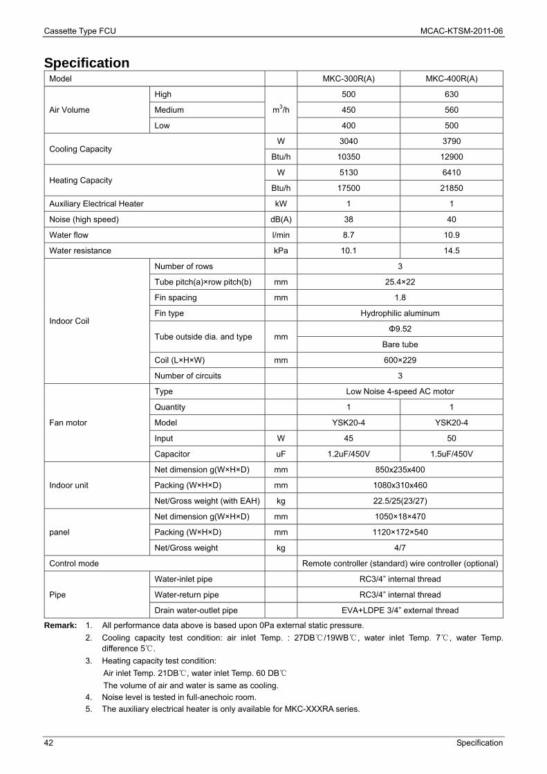
Specification Model MKC-300R(A) MKC-400R(A)
Air Volume
High
m3/h
500 630
Medium 450 560
Low 400 500
Cooling Capacity W 3040 3790
Btu/h 10350 12900
Heating Capacity W 5130 6410
Btu/h 17500 21850
Auxiliary Electrical Heater kW 1 1
Noise (high speed) dB(A) 38 40
Water flow l/min 8.7 10.9
Water resistance kPa 10.1 14.5
Indoor Coil
Number of rows 3
Tube pitch(a)×row pitch(b) mm 25.4×22
Fin spacing mm 1.8
Fin type Hydrophilic aluminum
Tube outside dia. and type mm Φ9.52
Bare tube
Coil (L×H×W) mm 600×229
Number of circuits 3
Fan motor
Type Low Noise 4-speed AC motor
Quantity 1 1
Model YSK20-4 YSK20-4
Input W 45 50
Capacitor uF 1.2uF/450V 1.5uF/450V
Indoor unit
Net dimension g(W×H×D) mm 850x235x400
Packing (W×H×D) mm 1080x310x460
Net/Gross weight (with EAH) kg 22.5/25(23/27)
panel
Net dimension g(W×H×D) mm 1050×18×470
Packing (W×H×D) mm 1120×172×540
Net/Gross weight kg 4/7
Control mode Remote controller (standard) wire controller (optional)
Pipe
Water-inlet pipe RC3/4” internal thread
Water-return pipe RC3/4” internal thread
Drain water-outlet pipe EVA+LDPE 3/4” external thread
Remark: 1. All performance data above is based upon 0Pa external static pressure.
2. Cooling capacity test condition: air inlet Temp. : 27DB℃/19WB℃, water inlet Temp. 7℃, water Temp. difference 5℃.
3. Heating capacity test condition:
Air inlet Temp. 21DB℃, water inlet Temp. 60 DB℃
The volume of air and water is same as cooling.
4. Noise level is tested in full-anechoic room.
5. The auxiliary electrical heater is only available for MKC-XXXRA series.

MCAC-KTSM-2011-06 Cassette Type FCU
Dimensions 43
Dimensions
MKC-300R(A), MKC-400R(A)
Cassette Type FCU MCAC-KTSM-2011-06
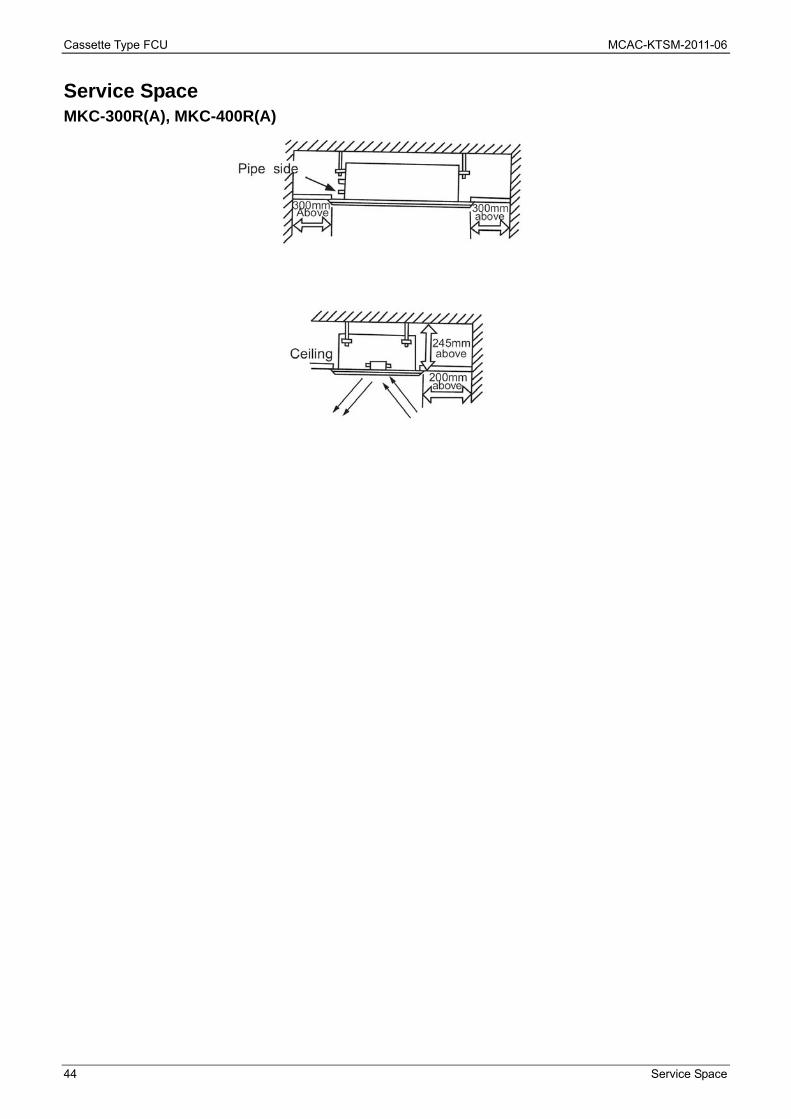
44 Service Space
Service Space MKC-300R(A), MKC-400R(A)

MCAC-KTSM-2011-06 Cassette Type FCU
Wiring Diagrams 45
Wiring Diagrams MKC-300R, MKC-300RA
Cassette Type FCU MCAC-KTSM-2011-06
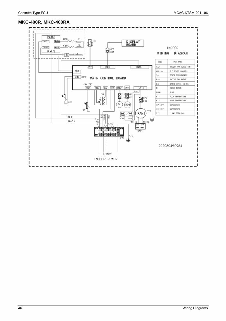
46 Wiring Diagrams
MKC-400R, MKC-400RA

MCAC-KTSM-2011-06 Cassette Type FCU
Capacity Tables 47
Capacity Tables Cooling Capacity: Remark: DB: Dry Bulb Temp.; WB: Wet Bulb Temp.; EWT: Enter Water Temp.; LWT: Leaving Water Temp.; TC: Total Cooling Capacity; SC: Sensible Cooling Capacity;
Model Speed
Air On FCU Water Delta Water
Capacity Water Flow
Water Pressure
Drop DB WB EWT LWT Temp. TC SC
℃ ℃ ℃ ℃ ℃ kW kW l/min kPa
MKC-300R(A) High
26.7 19.4 7 12 5 2.96 2.13 8.5 12
5.5 14.5 9 1.63 1.17 4.3 5
27 19 7 12 5 3.04 2.17 8.7 10.1
5.5 14.5 9 1.66 1.19 4.3 4.2
29 21 7 12 5 3.64 2.42 10.5 14
5.5 14.5 9 2 1.33 5.3 6.3
MKC-400R(A) High
26.7 19.4 7 12 5 3.72 2.74 10.7 17.16
5.5 14.5 9 2.05 1.51 5.3 7.15
27 19 7 12 5 3.79 2.8 10.9 14.5
5.5 14.5 9 2.08 1.54 5.5 6.01
29 21 7 12 5 4.61 3.12 13.2 20.02
5.5 14.5 9 2.54 1.72 6.7 9.01
Cooling capacity modification coefficient table:
Speed MKC-300R(A) MKC-400R(A)
TC SC TC SC
Mid 0.95 0.91 0.94 0.9
Lo 0.9 0.86 0.89 0.85

Cassette Type FCU MCAC-KTSM-2011-06
48 Capacity Tables
Heating Capacity: Remark: TH: Total Heating Capacity.
Model Speed
Water temp.
change
Air inlet temp. (21℃ DB)
Water inlet temp. (℃)
35 40 45 50 55 60 65 70
TH TH TH TH TH TH TH TH
℃ kW kW kW kW kW kW kW kW
MKC-300R(A) High
10 0.94 1.83 2.66 3.47 4.27 5.07 5.86 6.65
8 1.26 2.1 2.91 3.71 4.5 5.29 6.07 6.86
7 1.4 2.22 3.02 3.82 4.61 5.39 6.18 6.96
6 1.53 2.34 3.14 3.93 4.71 5.5 6.28 7.06
5 1.66 2.46 3.25 4.03 4.82 5.6 6.38 7.16
MKC-400R(A) High
10 1.13 2.24 3.29 4.32 5.34 6.36 7.37 8.37
8 1.53 2.59 3.62 4.64 5.65 6.66 7.66 8.67
7 1.72 2.76 3.78 4.79 5.8 6.81 7.81 8.81
6 1.89 2.92 3.94 4.94 5.95 6.95 7.95 8.95
5 2.06 3.08 4.09 5.09 6.09 7.09 8.1 9.1
Heating capacity modification coefficient table: Model MKC-300R(A) MKC-400R(A)
Mid-speed 0.89 0.88
Low-speed 0.84 0.83
MCAC-KTSM-2011-06 Cassette Type FCU
Sound Levels 49
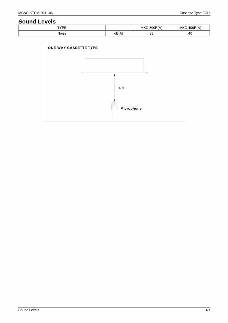
Sound Levels TYPE MKC-300R(A) MKC-400R(A)
Noise dB(A) 38 40
ONE-WAY CASSETTE TYPE
Microphone
1.0m
Cassette Type FCU MCAC-KTSM-2011-06
50 Explored View
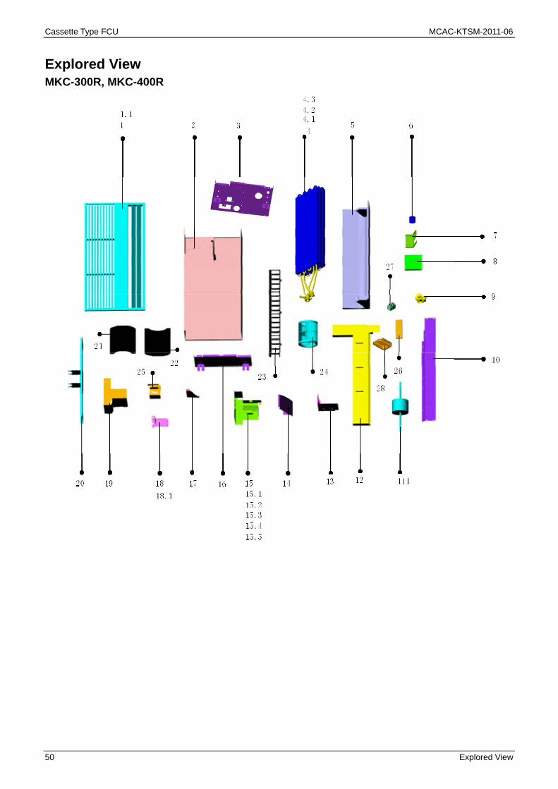
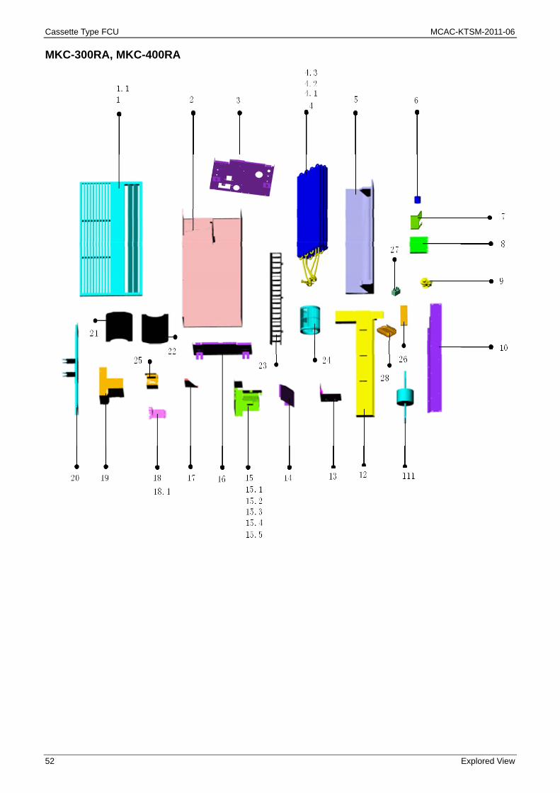
Explored View MKC-300R, MKC-400R

MCAC-KTSM-2011-06 Cassette Type FCU
Explored View 51
No. Part Name Quantity No. Part Name Quantity
1 Panel 1 15.1 Wiring box 1
1.1 Swing motor 1 15.2 Transformer 1
2 Base 1 15.3 Main PCB 1
3 Right side plate 1 15.4 Wiring terminal 1
4 Evaporator assembly 1 15.5 6-hole terminal 1
4.1 Tube temperature sensor 1 16 Left side plate 1
4.2 Indoor temperature sensor 1 17 Right cover of evaporator 1
4.3 Evaporator 1 18 Supporter of water level switch 1
5 Air leading foam 1 18.1 Water level sensor 1
6 Heat insulation of drain pipe 1 19 cover 1
7 Water leading plate 1 20 Supporter of motor 1
8 Small cover 1 21 Lower volute 2
9 Drain pump 1 22 Upper volute 2
10 Middle cover 1 23 Air louver 1
11 Fan motor 1 24 Fan wheel 2
12 Drain pan 1 25 Isolation panel of drain pump 1
13 Isolation panel of drain pump 1 26 Remote controller 1
14 Right cover of evaporator 1 27 Fan motor capacitor 1
15 Control box assembly 1 28 Supporter of remote controller 1
Cassette Type FCU MCAC-KTSM-2011-06
52 Explored View
MKC-300RA, MKC-400RA
MCAC-KTSM-2011-06 Cassette Type FCU
Explored View 53
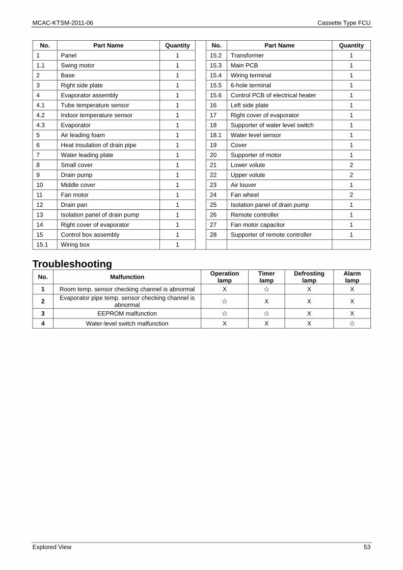
No. Part Name Quantity No. Part Name Quantity
1 Panel 1 15.2 Transformer 1
1.1 Swing motor 1 15.3 Main PCB 1
2 Base 1 15.4 Wiring terminal 1
3 Right side plate 1 15.5 6-hole terminal 1
4 Evaporator assembly 1 15.6 Control PCB of electrical heater 1
4.1 Tube temperature sensor 1 16 Left side plate 1
4.2 Indoor temperature sensor 1 17 Right cover of evaporator 1
4.3 Evaporator 1 18 Supporter of water level switch 1
5 Air leading foam 1 18.1 Water level sensor 1
6 Heat insulation of drain pipe 1 19 Cover 1
7 Water leading plate 1 20 Supporter of motor 1
8 Small cover 1 21 Lower volute 2
9 Drain pump 1 22 Upper volute 2
10 Middle cover 1 23 Air louver 1
11 Fan motor 1 24 Fan wheel 2
12 Drain pan 1 25 Isolation panel of drain pump 1
13 Isolation panel of drain pump 1 26 Remote controller 1
14 Right cover of evaporator 1 27 Fan motor capacitor 1
15 Control box assembly 1 28 Supporter of remote controller 1
15.1 Wiring box 1
Troubleshooting No. Malfunction
Operation lamp
Timer lamp
Defrosting lamp
Alarm lamp
1 Room temp. sensor checking channel is abnormal X ☆ X X
2 Evaporator pipe temp. sensor checking channel is
abnormal ☆ X X X
3 EEPROM malfunction ☆ ☆ X X
4 Water-level switch malfunction X X X ☆

Cassette Type FCU MCAC-KTSM-2011-06
54 Installation
Part 3 Installation
The Installation of MKC ...................................................... 55
The Installation of MKA ...................................................... 63
The Installation of MKD ...................................................... 73

MCAC-KTSM-2011-06 Cassette Type FCU
The Installation of MKC 55
The Installation of MKC
Installation Attention ............................................................ 56
Install the Main Body .......................................................... 57
Install the Panel ................................................................... 59
Install Drain Pipe ................................................................. 60
Wring .................................................................................... 62
Cassette Type FCU MCAC-KTSM-2011-06
56 The Installation of MKC
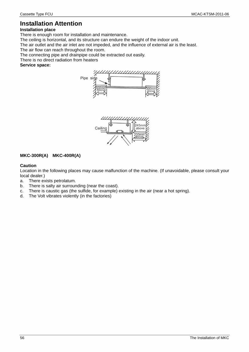
Installation Attention Installation place There is enough room for installation and maintenance. The ceiling is horizontal, and its structure can endure the weight of the indoor unit. The air outlet and the air inlet are not impeded, and the influence of external air is the least. The air flow can reach throughout the room. The connecting pipe and drainpipe could be extracted out easily. There is no direct radiation from heaters Service space:
MKC-300R(A) MKC-400R(A) Caution Location in the following places may cause malfunction of the machine. (If unavoidable, please consult your local dealer.) a. There exists petrolatum. b. There is salty air surrounding (near the coast). c. There is caustic gas (the sulfide, for example) existing in the air (near a hot spring). d. The Volt vibrates violently (in the factories)

MCAC-KTSM-2011-06 Cassette Type FCU
The Installation of MKC 57
Install the Main Body Please refer to the following figure for the hanging screw bolts. Please install with Ø10 hanging screw bolts. The handling to the ceiling varies from the constructions, consult the construction person for the specific
condition. 1. The size of the ceiling to be handled------ Do keep the ceiling flat. Consolidate the roof beam for
possible vibration. 2. Cut off the roof beam. 3. Strengthen the place that has been cut off, and consolidate the roof beam. 4. Connect wires and pipes inside the ceiling after the air conditioner is hanged.
MKC-300R(A) MKC-400R(A) After the selection of installation location, position the water pipes, drain pipes, indoor & outdoor wires to
the connection places before hanging up the machine. The installation of hanging screw bolts.

Cassette Type FCU MCAC-KTSM-2011-06
58 The Installation of MKC
Install the hanging bolt into U groove of the hanging tool. Overhang the indoor unit and ensure it is level using a level gauge.

MCAC-KTSM-2011-06 Cassette Type FCU
The Installation of MKC 59
Install the Panel Note: The panel and the ceiling, the panel and the unit body should be connected closely, or air leakage,
water leakage and condensate dew will be caused. Please refer to the panel installation manual to install the panel. Please confirm if the installation places of unit body and panel are proper.

Cassette Type FCU MCAC-KTSM-2011-06
60 The Installation of MKC
Install Drain Pipe When connecting the pipe, please use the sealing material and pipe glove. Caution: The drain pipe of indoor unit must be heat insulated, or it will condense dew, as well as the connections
of the indoor unit. Hard PVC binder must be used for pipe connection, and make sure there is no leakage. With the connection part to the indoor unit, please note not to impose pressure on the side of indoor unit
pipes. When the declivity of the drain pipe downwards is over 1/100, there should not be any winding. The total length of the drain pipe when pulled out breadth wise shall not exceed 20m. When the pipe is
over long, a bracket must be installed to prevent winding. Refer to the following figures to install the pipes. Note 1. Injury means causing from the harm, burn and electrical shock, but not serious for the hospitalization. 2. The damage of material means the disrepair of property and material. Upward drainage: To make sure that the drainage pipe would not slant downward. Lead it upward to a height 750mm
maximum, then downward lead it. When the drainage is upward, the upward drain pipe and elbow of the accessories must be adopted and
the height is less than 750mm, otherwise the drain pump water level switch malfunction will be caused.
After upward piping, the lead drain pipe must slant downward immediately. (Over 1/100)
As long as possible about(10cm)
Lean downward over 1/100
Vp30
1.5m~2m
Lean downward over 1/100Insulation material
Bend

MCAC-KTSM-2011-06 Cassette Type FCU
The Installation of MKC 61
Drainage test Check whether the drainpipe is unhindered New built house should have this test done before paving the ceiling. 1) Stow 600-800cc water with pot or hose from outlet slowly. 2) Turn on the power, and operate the air conditioner under the "COOLING" mode. The drainage test is
doing during checking the drain pump motor running sound. 3) Turn off the power, drain the water away. Pipe connection 1. The water vent is with the air outlet valve; the other side is water inlet. 2. When connecting the water collecting box, the torque is 60~75N·m. 3. Put the connecting tubing at the proper position, wrench the nuts with hands, then fasten it with a
wrench.( Refer to Chart)

Cassette Type FCU MCAC-KTSM-2011-06
62 The Installation of MKC
Wring Caution: 1. The air conditioner should use separate power supply with rated voltage; the voltage of power supply
must be within90%~110% of rated value. 2. The wiring work should be done by qualified persons according to circuit drawing. 3. A disconnection device having an air gap contact separation in all active conductors should
incorporated in the fixed wiring according to the National wiring regulation. 4. Be sure to locate the power wiring and the signal wiring well to avoid cross-disturbance and their
contact with connecting pipe or stop valve body. 5. The wiring (5-core shield cable) attached between the signal receiving board and the wire controller is
not more than 2m. Be sure to prolong it with wiring of the same type and proper length if necessary. Generally, do not twist two wiring together unless .the joint is soldered well and covered with insulator tape.
6. Do not turn on the power until you have checked carefully after wiring. 7. The yellow and green wire can only be used to link to the ground wiring. Terminal Board Diagram Please refer to the indoor unit wiring diagram for the wiring.
To wire controller
The reserved wire control function is indicated in broken line table, users can purchase the wire controller when necessary.
MCAC-KTSM-2011-06 Cassette Type FCU
The Installation of MKA 63
The Installation of MKA
1. Before Installation ................................................................................ 64
2. Installation space .................................................................................. 64
3. Installation procedures for fresh air intake duct connection ........... 64
4. Install the Main Body ............................................................................ 65
5. Install the Panel .................................................................................... 68
6. Connect the Drain Pipe ........................................................................ 70
7. Wiring ..................................................................................................... 72

Cassette Type FCU MCAC-KTSM-2011-06
64 The Installation of MKA
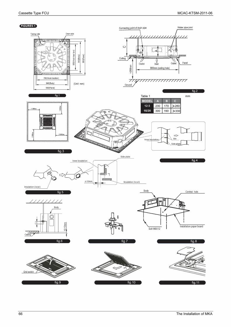
1. Before Installation Please check whether the accessories are of full scope. If there are some fittings free from use, please restore them carefully.
2. Installation space (refer to fig.1,fig.2,fig.3 and table 1 for specification.) The indoor unit should be installed in a location that meets the following requirements: There is enough room for installation and maintenance. The ceiling is horizontal, and its structure can endure the weight of the indoor unit. The outlet and the inlet are not impeded, and the influence of external air is the least. The air flow can reach throughout the room. The connecting water pipe and drainpipe could be extracted out easily. There is no direct radiation from heaters. Caution: Keep indoor unit, outdoor unit, power supply wiring and transmission wiring at least 1 meter away from televisions and radios. This is to prevent image interference and noise in those electrical appliances. (Noise may be generated depending on the conditions under which the electric wave is generated, even if 1 meter is kept.)
3. Installation procedures for fresh air intake duct connection Preparing the connection hole Cut off the knockout hole on the side plate with a nipper. Cut the inner insulation of the hole portion with a cutter. Placing the insulation Put the insulation tightly around the hole of the unit as shown. The ends of the side plate and the inner
insulation must be completely adhered without leaving any clearance along the circumference of the hole. Make sure the inner surface of insulation tightly contacts the inner insulation edge and the side plate. (refer to fig.5)
MCAC-KTSM-2011-06 Cassette Type FCU
The Installation of MKA 65
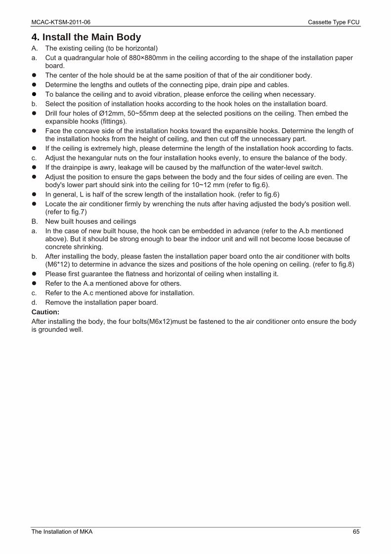
4. Install the Main Body A. The existing ceiling (to be horizontal) a. Cut a quadrangular hole of 880×880mm in the ceiling according to the shape of the installation paper
board. The center of the hole should be at the same position of that of the air conditioner body. Determine the lengths and outlets of the connecting pipe, drain pipe and cables. To balance the ceiling and to avoid vibration, please enforce the ceiling when necessary. b. Select the position of installation hooks according to the hook holes on the installation board. Drill four holes of Ø12mm, 50~55mm deep at the selected positions on the ceiling. Then embed the
expansible hooks (fittings). Face the concave side of the installation hooks toward the expansible hooks. Determine the length of
the installation hooks from the height of ceiling, and then cut off the unnecessary part. If the ceiling is extremely high, please determine the length of the installation hook according to facts. c. Adjust the hexangular nuts on the four installation hooks evenly, to ensure the balance of the body. If the drainpipe is awry, leakage will be caused by the malfunction of the water-level switch. Adjust the position to ensure the gaps between the body and the four sides of ceiling are even. The
body's lower part should sink into the ceiling for 10~12 mm (refer to fig.6). In general, L is half of the screw length of the installation hook. (refer to fig.6) Locate the air conditioner firmly by wrenching the nuts after having adjusted the body's position well.
(refer to fig.7) B. New built houses and ceilings a. In the case of new built house, the hook can be embedded in advance (refer to the A.b mentioned
above). But it should be strong enough to bear the indoor unit and will not become loose because of concrete shrinking.
b. After installing the body, please fasten the installation paper board onto the air conditioner with bolts (M6*12) to determine in advance the sizes and positions of the hole opening on ceiling. (refer to fig.8)
Please first guarantee the flatness and horizontal of ceiling when installing it. Refer to the A.a mentioned above for others. c. Refer to the A.c mentioned above for installation. d. Remove the installation paper board. Caution: After installing the body, the four bolts(M6x12)must be fastened to the air conditioner onto ensure the body is grounded well.
Cassette Type FCU MCAC-KTSM-2011-06
66 The Installation of MKA

MCAC-KTSM-2011-06 Cassette Type FCU
The Installation of MKA 67

Cassette Type FCU MCAC-KTSM-2011-06
68 The Installation of MKA
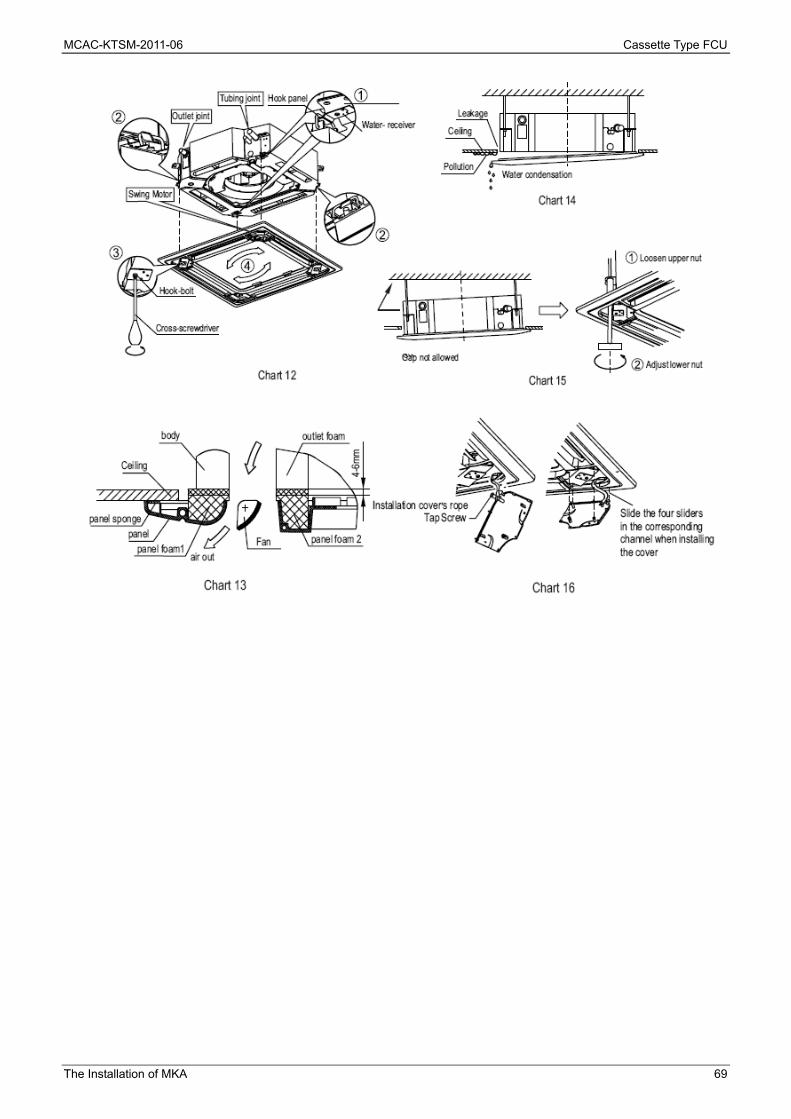
5. Install the Panel Caution: Never put the panel face down on floor or against the wall, or on bulgy objects. Never crash or strike it. (1) Remove the air inlet grill. a. Slide two grid switches toward the middle at the same time, and then pull them up. (Refer to fig. 9) b. Draw the grid up to an angle of about 45o, and remove it. (Refer to fig. 10) (2) Remove the installation covers at the four corners. Wrench off the bolts, loose the rope of the installation covers, and remove them. (Refer to fig. 11) (3) Install the panel a. Align the swing motor on the panel to the tubing joints of the body properly. b. Fix hooks of the panel at swing motor and its opposite sides to the hooks of corresponding water
receiver. Then hang the other two panel hooks onto corresponding hangers of the body. Cautions Do not coil the wiring of the swing motor into the seal sponge. c. Adjust the four panel hook screws to keep the panel horizontal, and screw them up to the ceiling evenly.
(Refer to chart 12) d. Regulate the panel in the direction of the arrow in Chart12 slightly to fit the panel's center to the center
of the ceiling's opening. Guarantee that hooks of four corners are fixed well. e. Keep fastening the screws under the panel hooks, until the thickness of the sponge between the body
and the panel's outlet has been reduced to about 4~6mm. The edge of the panel should contact with the ceiling well. (Refer to chart 13)
Malfunction described in Chart14 can be caused by inappropriate tightness the screw. If the gap between the panel and ceiling still exists after fastening the screws, the height of the indoor unit should be modified again. (Refer to chart 15-left) You can modify the height of the indoor unit through the openings on the panel's four corners; if the lift of the indoor unit and the drainpipe is not influenced (refer to chart 15-right). (4) Hang the air-in grid to the panel, and then connect the lead terminator of the swing motor and
that of the control box with corresponding terminators on the body respectively. (5) Relocate the air-in grid in the procedure of reversed order. (6) Relocate the installation cover. a. Fasten the rope of installation cover on the bolt of the installation cover. (Refer to chart 16-left) b. Press the installation cover into the panel slightly. (Refer to chart 16-right)
MCAC-KTSM-2011-06 Cassette Type FCU
The Installation of MKA 69
Cassette Type FCU MCAC-KTSM-2011-06
70 The Installation of MKA
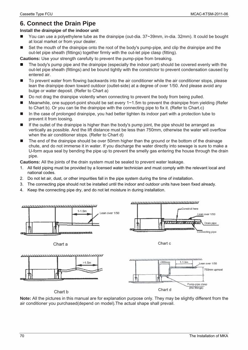
6. Connect the Drain Pipe Install the drainpipe of the indoor unit You can use a polyethylene tube as the drainpipe (out-dia. 37~39mm, in-dia. 32mm). It could be bought
at local market or from your dealer. Set the mouth of the drainpipe onto the root of the body's pump-pipe, and clip the drainpipe and the
out-let pipe sheath (fittings) together firmly with the out-let pipe clasp (fitting). Cautions: Use your strength carefully to prevent the pump-pipe from breaking. The body's pump pipe and the drainpipe (especially the indoor part) should be covered evenly with the
out-let pipe sheath (fittings) and be bound tightly with the constrictor to prevent condensation caused by entered air.
To prevent water from flowing backwards into the air conditioner while the air conditioner stops, please lean the drainpipe down toward outdoor (outlet-side) at a degree of over 1/50. And please avoid any bulge or water deposit. (Refer to Chart a)
Do not drag the drainpipe violently when connecting to prevent the body from being pulled. Meanwhile, one support-point should be set every 1~1.5m to prevent the drainpipe from yielding (Refer
to Chart b). Or you can tie the drainpipe with the connecting pipe to fix it. (Refer to Chart.c) In the case of prolonged drainpipe, you had better tighten its indoor part with a protection tube to
prevent it from loosing. If the outlet of the drainpipe is higher than the body's pump joint, the pipe should be arranged as
vertically as possible. And the lift distance must be less than 750mm, otherwise the water will overflow when the air conditioner stops. (Refer to Chart d)
The end of the drainpipe should be over 50mm higher than the ground or the bottom of the drainage chute, and do not immerse it in water. If you discharge the water directly into sewage is sure to make a U-form aqua seal by bending the pipe up to prevent the smelly gas entering the house through the drain pipe.
Cautions: All the joints of the drain system must be sealed to prevent water leakage. 1. All field piping must be provided by a licensed water technician and must comply with the relevant local and
national codes. 2. Do not let air, dust, or other impurities fall in the pipe system during the time of installation. 3. The connecting pipe should not be installed until the indoor and outdoor units have been fixed already. 4. Keep the connecting pipe dry, and do not let moisture in during installation.
Note: All the pictures in this manual are for explanation purpose only. They may be slightly different from the air conditioner you purchased(depend on model).The actual shape shall prevail.
MCAC-KTSM-2011-06 Cassette Type FCU
The Installation of MKA 71
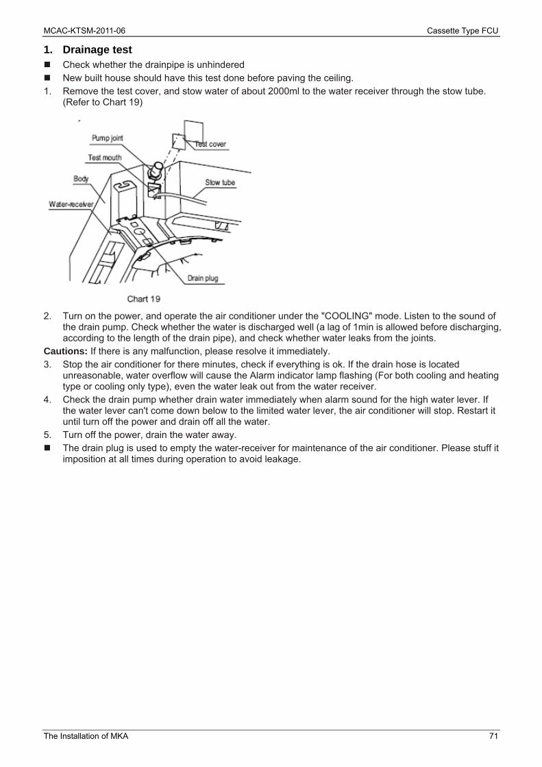
1. Drainage test Check whether the drainpipe is unhindered New built house should have this test done before paving the ceiling. 1. Remove the test cover, and stow water of about 2000ml to the water receiver through the stow tube.
(Refer to Chart 19)
2. Turn on the power, and operate the air conditioner under the "COOLING" mode. Listen to the sound of
the drain pump. Check whether the water is discharged well (a lag of 1min is allowed before discharging, according to the length of the drain pipe), and check whether water leaks from the joints.
Cautions: If there is any malfunction, please resolve it immediately. 3. Stop the air conditioner for there minutes, check if everything is ok. If the drain hose is located
unreasonable, water overflow will cause the Alarm indicator lamp flashing (For both cooling and heating type or cooling only type), even the water leak out from the water receiver.
4. Check the drain pump whether drain water immediately when alarm sound for the high water lever. If the water lever can't come down below to the limited water lever, the air conditioner will stop. Restart it until turn off the power and drain off all the water.
5. Turn off the power, drain the water away. The drain plug is used to empty the water-receiver for maintenance of the air conditioner. Please stuff it
imposition at all times during operation to avoid leakage.

Cassette Type FCU MCAC-KTSM-2011-06
72 The Installation of MKA
7. Wiring Caution: 1. The air conditioner should use separate power supply with rated voltage. 2. The external power supply to the air conditioner should have ground wiring, which is linked to the
ground wiring of the indoor and outdoor unit. 3. The wiring work should be done by qualified persons according to circuit drawing. 4. An all-pole disconnection switch having a contract separation of at least 3mm in a pole should be
connected in fixed wiring. 5. Be sure to locate the power wiring and the signal wiring well to avoid cross-disturbance.
6. Do not turn on the power until you have checked carefully after wiring. Note: Remark per EMC Directive 89/336/EEC to prevent flicker impressions during the start of the compressor (technical process), following installation conditions do apply. 1. The power connection for the air conditioner has to be done at the main power distribution. The
distribution has to be of a low impedance, normally the required impedance reaches at a 32 A fusing point.
2. No other equipment has to be connected with this power line. 3. For detailed installation acceptance please refer to your power supplier, if restrictions do apply for
products like washing machines, air conditioners or electrical ovens. 4. For power details of the air conditioner refer to the rating plate of the product. 5. For any question contact your local dealer.
1. Connect the cable Dissemble the bolts from the cover.(If there isn't a cover on the outdoor unit, disassemble the bolts from
the maintenance board, and pull it in the direction of the arrow to remove the protection board.) Connect the connective cables to the terminals as identified with their respective mached numbers on
the terminal block of indoor and outdoor units. Re-install the cover or the protection board.
2. Wiring figure
Note: If the supply cord is damaged, it must be replaced by the manufacturer or its service agent or a similarly qualified person in order to avoid a haza

MCAC-KTSM-2011-06 Cassette Type FCU
The Installation of MKD 73
The Installation of MKD 1 Installation space ............................................................. 74
2 Install the main body ....................................................... 74
3 Install the Panel ................................................................ 75
4 Connect the Drain Pipe ................................................... 76
5 Wiring ................................................................................ 78
6 Test operation .................................................................. 80

Cassette Type FCU MCAC-KTSM-2011-06
74 The Installation of MKD
Installation 1 Installation space The indoor unit should be installed in a location that meets the following requirements: There is enough room for installation and maintenance. The ceiling is horizontal, and its structure can endure the weight of the indoor unit. The outlet and the inlet are not impeded, and the influence of external air is the least. The air flow can reach throughout the room. The connecting water pipe and drainpipe could be extracted out easily. There is no direct radiation from heaters. Caution: Keep indoor unit, outdoor unit, power supply wiring and transmission wiring at least 1 meter away from televisions and radios. This is to prevent image interference and noise in those electrical appliances. (Noise may be generated depending on the conditions under which the electric wave is generated, even if 1 meter is kept.)
2 Install the main body A. The existing ceiling (to be horizontal) a. Cut a quadrangular hole of 880×880mm in the ceiling according to the shape of the installation paper
board. The center of the hole should be at the same position of that of the air conditioner body. Determine the lengths and outlets of the connecting pipe, drain pipe and cables. To balance the ceiling and to avoid vibration, please enforce the ceiling when necessary. b. Select the position of installation hooks according to the hook holes on the installation board. Drill four holes of Ø12mm, 50~55mm deep at the selected positions on the ceiling. Then embed the
expansible hooks (fittings). Face the concave side of the installation hooks toward the expansible hooks. Determine the length of
the installation hooks from the height of ceiling, and then cut off the unnecessary part. If the ceiling is extremely high, please determine the length of the installation hook according to facts. c. Adjust the hexangular nuts on the four installation hooks evenly, to ensure the balance of the body. If the drainpipe is awry, leakage will be caused by the malfunction of the water-level switch. Adjust the position to ensure the gaps between the body and the four sides of ceiling are even. The
body's lower part should sink into the ceiling for 10~12 mm.
In general, L is half of the screw length of the installation hook. Locate the air conditioner firmly by wrenching the nuts after having adjusted the body's position well.
MCAC-KTSM-2011-06 Cassette Type FCU
The Installation of MKD 75
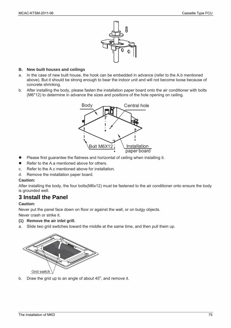
B. New built houses and ceilings a. In the case of new built house, the hook can be embedded in advance (refer to the A.b mentioned
above). But it should be strong enough to bear the indoor unit and will not become loose because of concrete shrinking.
b. After installing the body, please fasten the installation paper board onto the air conditioner with bolts (M6*12) to determine in advance the sizes and positions of the hole opening on ceiling.
Please first guarantee the flatness and horizontal of ceiling when installing it. Refer to the A.a mentioned above for others. c. Refer to the A.c mentioned above for installation. d. Remove the installation paper board. Caution: After installing the body, the four bolts(M6x12) must be fastened to the air conditioner onto ensure the body is grounded well.
3 Install the Panel Caution: Never put the panel face down on floor or against the wall, or on bulgy objects. Never crash or strike it. (1) Remove the air inlet grill. a. Slide two grid switches toward the middle at the same time, and then pull them up.
b. Draw the grid up to an angle of about 45o, and remove it.

Cassette Type FCU MCAC-KTSM-2011-06
76 The Installation of MKD
(2) Remove the installation covers at the four corners. Wrench off the bolts, loose the rope of the installation covers, and remove them.
(3) Install the panel a. Align the swing motor on the panel to the tubing joints of the body properly. b. Fix hooks of the panel at swing motor and its opposite sides to the hooks of corresponding water
receiver. Then hang the other two panel hooks onto corresponding hangers of the body. Cautions Do not coil the wiring of the swing motor into the seal sponge. c. Adjust the four panel hook screws to keep the panel horizontal, and screw them up to the ceiling evenly. d. Regulate the panel in the direction of the arrow slightly to fit the panel's center to the center of the
ceiling's opening. Guarantee that hooks of four corners are fixed well. e. Keep fastening the screws under the panel hooks, until the thickness of the sponge between the body
and the panel's outlet has been reduced to about 4~6mm. The edge of the panel should contact with the ceiling well.
If the gap between the panel and ceiling still exists after fastening the screws, the height of the indoor unit should be modified again. You can modify the height of the indoor unit through the openings on the panel's four corners; if the lift of the indoor unit and the drainpipe is not influenced. (4) Hang the air-in grid to the panel, and then connect the lead terminator of the swing motor and
that of the control box with corresponding terminators on the body respectively. (5) Relocate the air-in grid in the procedure of reversed order. (6) Relocate the installation cover. a. Fasten the rope of installation cover on the bolt of the installation cover. (Refer to chart 16-left) b. Press the installation cover into the panel slightly. (Refer to chart 16-right)
4 Connect the Drain Pipe 4.1 Install the drainpipe You can use a polyethylene tube as the drainpipe (out-dia. 37~39mm, in-dia. 32mm). It could be bought
at local market or from your dealer. Set the mouth of the drainpipe onto the root of the body's pump-pipe, and clip the drainpipe and the
out-let pipe sheath (fittings) together firmly with the out-let pipe clasp (fitting). Cautions: Use your strength carefully to prevent the pump-pipe from breaking. The body's pump pipe and the drainpipe (especially the indoor part) should be covered evenly with the
out-let pipe sheath (fittings) and be bound tightly with the constrictor to prevent condensation caused by entered air.
To prevent water from flowing backwards into the air conditioner while the air conditioner stops, please lean the drainpipe down toward outdoor (outlet-side) at a degree of over 1/50. And please avoid any bulge or water deposit. (Refer to the following)

MCAC-KTSM-2011-06 Cassette Type FCU
The Installation of MKD 77
Do not drag the drainpipe violently when connecting to prevent the body from being pulled. Meanwhile, one support-point should be set every 1~1.5m to prevent the drainpipe from yielding. Or
you can tie the drainpipe with the connecting pipe to fix it.
In the case of prolonged drainpipe, you had better tighten its indoor part with a protection tube to prevent it from loosing.
If the outlet of the drainpipe is higher than the body's pump joint, the pipe should be arranged as vertically as possible. And the lift distance must be less than 500mm, otherwise the water will overflow when the air conditioner stops.
The end of the drainpipe should be over 50mm higher than the ground or the bottom of the drainage
chute, and do not immerse it in water. If you discharge the water directly into sewage is sure to make a U-form aqua seal by bending the pipe up to prevent the smelly gas entering the house through the drain pipe.
Cautions: All the joints of the drain system must be sealed to prevent water leakage. 5. All field piping must be provided by a licensed water technician and must comply with the relevant local
and national codes. 6. Do not let air, dust, or other impurities fall in the pipe system during the time of installation. 7. The connecting pipe should not be installed until the indoor and outdoor units have been fixed already. 8. Keep the connecting pipe dry, and do not let moisture in during installation. Note: All the pictures in this manual are for explanation purpose only. They may be slightly different from the air conditioner you purchased (depend on model).The actual shape shall prevail. 4.2 Drainage test Check whether the drainpipe is unhindered. New built house should have this test done before paving the ceiling. 1. Remove the test cover, and stow water of about 2000ml to the water receiver through the stow tube.

Cassette Type FCU MCAC-KTSM-2011-06
78 The Installation of MKD
2. Turn on the power, and operate the air conditioner under the "COOLING" mode. Listen to the sound of the drain pump. Check whether the water is discharged well (a lag of 1min is allowed before discharging, according to the length of the drain pipe), and check whether water leaks from the joints. Cautions: If there is any malfunction, please resolve it immediately. 3. Stop the air conditioner for there minutes, check if everything is ok. If the drain hose is located
unreasonable, water overflow will cause the Alarm indicator lamp flashing (For both cooling and heating type or cooling only type), even the water leak out from the water receiver.
4. Check the drain pump whether drain water immediately when alarm sound for the high water lever. If the water lever can't come down below to the limited water lever, the air conditioner will stop. Restart it until turn off the power and drain off all the water.
5. Turn off the power, drain the water away. The drain plug is used to empty the water-receiver for maintenance of the air conditioner. Please stuff it
imposition at all times during operation to avoid leakage.
5 Wiring Caution: 1. The air conditioner should use separate power supply with rated voltage. 2. The external power supply to the air conditioner should have ground wiring, which is linked to the
ground wiring of the indoor and outdoor unit. 3. The wiring work should be done by qualified persons according to circuit drawing. 4. An all-pole disconnection switch having a contract separation of at least 3mm in a pole should be
connected in fixed wiring. 5. Be sure to locate the power wiring and the signal wiring well to avoid cross-disturbance. 6. Do not turn on the power until you have checked carefully after wiring. Note: Remark per EMC Directive 89/336/EEC to prevent flicker impressions during the start of the compressor (technical process), following installation conditions do apply. 6. The power connection for the air conditioner has to be done at the main power distribution. The
distribution has to be of a low impedance, normally the required impedance reaches at a 32A fusing point.
7. No other equipment has to be connected with this power line. 8. For detailed installation acceptance please refer to your power supplier, if restrictions do apply for
products like washing machines, air conditioners or electrical ovens. 9. For power details of the air conditioner refer to the rating plate of the product. 10. For any question contact your local dealer.
5.1 Connect the cable
Dissemble the bolts from the cover.(If there isn't a cover on the outdoor unit, disassemble the bolts from the maintenance board, and pull it in the direction of the arrow to remove the protection board.)
Connect the connective cables to the terminals as identified with their respective matched numbers on the terminal block of indoor and outdoor units.
Re-install the cover or the protection board.
MCAC-KTSM-2011-06 Cassette Type FCU
The Installation of MKD 79
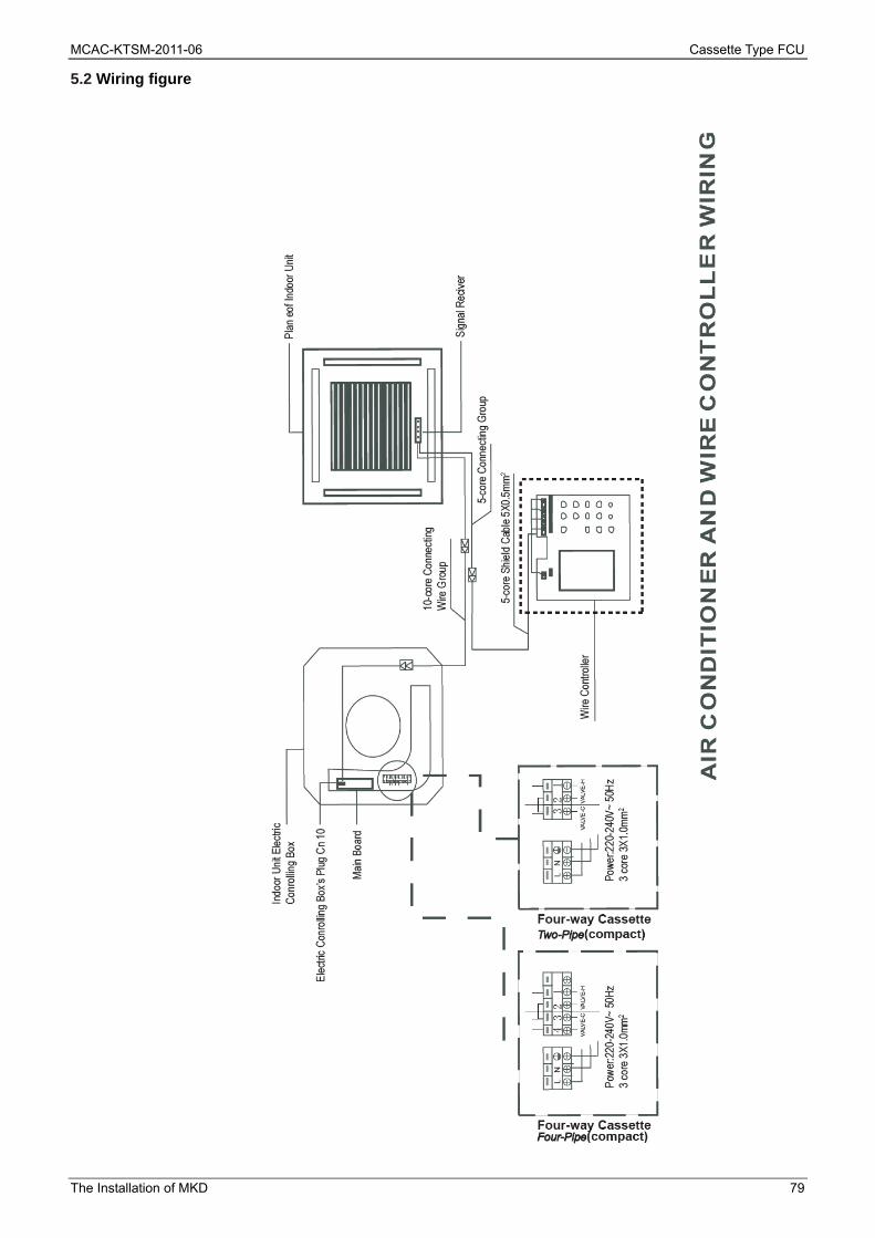
5.2 Wiring figure

Cassette Type FCU MCAC-KTSM-2011-06
80 The Installation of MKD
6 Test operation (1) The test operation must be carried out after the entire installation has been completed. (2) Please confirm the following points before the test operation. The indoor unit and outdoor unit are installed properly. Tubing and wiring are correctly completed. The refrigerant pipe system is leakage-checked. The drainage is unimpeded. The ground wiring is connected correctly. The length of the tubing and the added stow capacity of the refrigerant have been recorded. The power voltage fits the rated voltage of the air conditioner. There is no obstacle at the outlet and inlet of the outdoor and indoor units. The gas-side and liquid-side stop values are both opened. The air conditioner is pre-heated by turning on the power. (3) According to the user's requirement, install the remote controller when the remote controller's signal can reach the indoor unit smoothly. (4) Test operation Set the air conditioner under the mode of "COOLING" with the remote controller, and check the following points. ● Whether the switch on the remote controller works well. ● Whether the buttons on the remote controller works well. ● Whether the air flow louver moves normally. ● Whether the room temperature is adjusted well. ● Whether the indicator lights normally. ● Whether the temporary buttons works well. ● Whether the drainage is normal. ● Whether there is vibration or abnormal noise during operation. ● Whether the air conditioner heats well in the case of the HEATING/COOLING type.

MCAC-KTSM-2011-06 Cassette Type FCU
Controller 81
Part 4 Controller
Wireless remote controller R51/E ..................................... 82
Wireless remote controller R05/BGE ................................ 84

Cassette Type FCU MCAC-KTSM-2011-06
82 Controller
Wireless remote controller R51/E Suitable for One-way Cassette type, Compact Four-way Cassette type and Wall-mounted type:
Remote Controller Specifications
Model R51/E
Rated Voltage 3.0V
Lowest Voltage of CPU Emitting Signal 2.0V
Reaching Distance 8m (when using 3.0 voltage, it can get 11m)
Environment Temperature Range -5℃~60℃
Introduction of Function Buttons on the Remote Controller
1. TEMP DOWN Button: Push the TEMP DOWN button to decrease the indoor temperature setting or to adjust the timer in a counter-clockwise direction.
2. MODLE SELECT Button: Each time you push the button, a mode is selected in a sequence that goes from AUTO, COOL, DRY, HEAT and FAN as the following figure indicates:
MCAC-KTSM-2011-06 Cassette Type FCU
Controller 83
3. SWING Button: Push this switch button to change the louver angle. 4. RESET Button: When the RESET button is pushed, all of the current settings are cancelled and the
control will return to the initial settings. 5. ECONOMIC RUNNING Button: Push this button to go into the Energy-Saving operation mode. 6. LOCK Button: Push this button to lock in all the current settings. To release settings, push again. 7. CANCEL Button: Push this button to cancel the TIMER settings. 8. TIMER Button: This button is used to preset the time ON (start to operate) and the time OFF (turn off
the operation) 9. ON/OFF Button: Push this button to start the unit operation. Push the button again to stop the unit
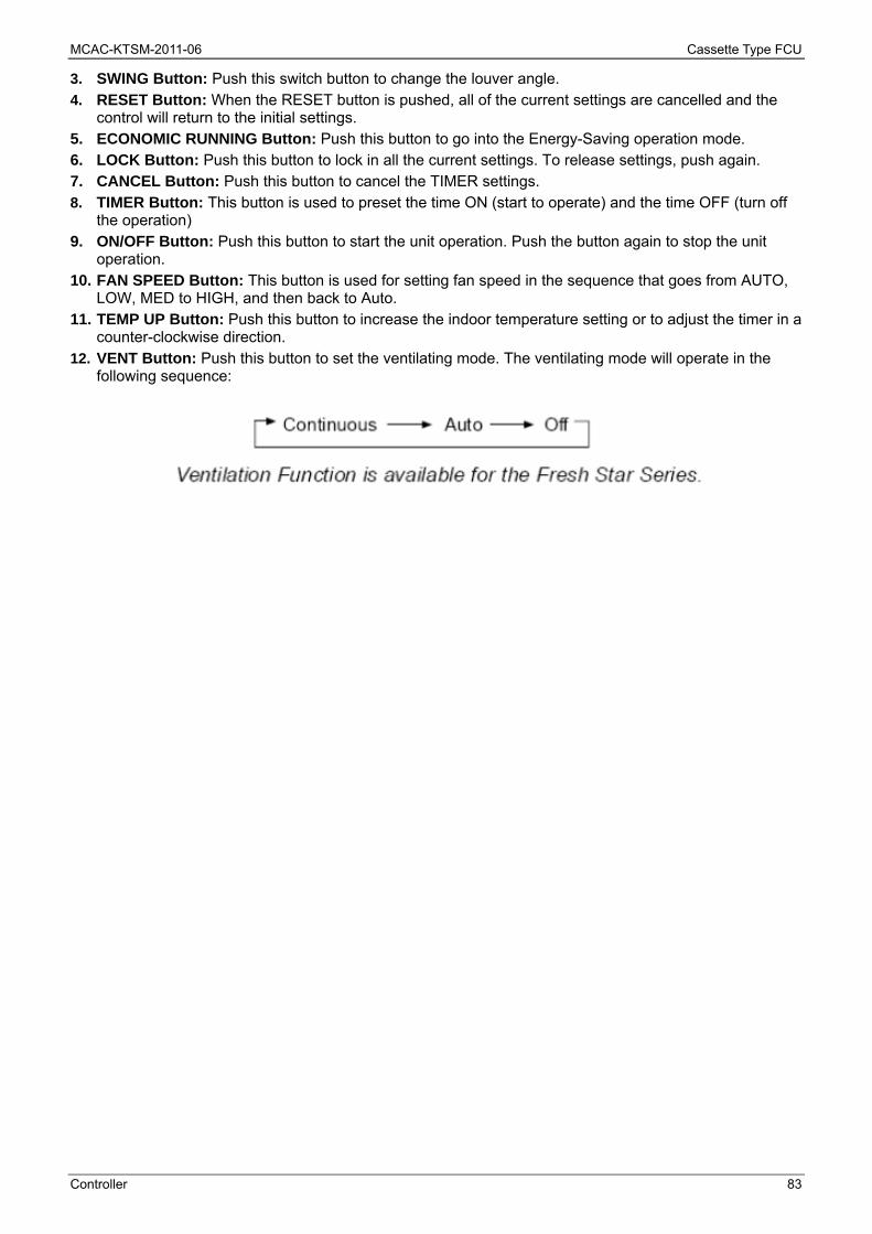
operation. 10. FAN SPEED Button: This button is used for setting fan speed in the sequence that goes from AUTO,
LOW, MED to HIGH, and then back to Auto. 11. TEMP UP Button: Push this button to increase the indoor temperature setting or to adjust the timer in a
counter-clockwise direction. 12. VENT Button: Push this button to set the ventilating mode. The ventilating mode will operate in the
following sequence:

Cassette Type FCU MCAC-KTSM-2011-06
84 Controller
Wireless remote controller R05/BGE Suitable for Four-way Cassette type:
Visual photo Note: 1. The outline figure on cover is for reference only, which may differ from what you purchased. 2. Make sure to read chapter PRECAUTIONS before you operate the air conditioner. 3. The content is available for model R05/BG. 4. R05/BGE can be applicable for cool only type and cool & heat type air conditioners.