mcac-atsm-2016-02 dc inverter aqua mini chiller 50hz content
TRANSCRIPT

MCAC-ATSM-2016-02 DC Inverter Aqua Mini Chiller 50Hz
1
Content
1. OUTDOOR UNITS LINEUP ................................................................................... 1
2. NOMENCLATURE .............................................................................................. 3
3. FEATURES ...................................................................................................... 4
4. DESCRIPTION OF MAIN COMPONENTS ................................................................. 7
5. SPECIFICATIONS .............................................................................................. 9
6. DIMENSIONS ................................................................................................. 13
7. PIPING DIAGRAM ............................................................................................ 14
8. WIRING DIAGRAM ........................................................................................... 15
9. ELECTRIC CHARACTERISTICS .......................................................................... 18
10. CAPACITY TABLES ........................................................................................ 19
11. OPERATION LIMITS ....................................................................................... 26
12. HYDRAULIC DATA ......................................................................................... 28
13. SOUND LEVEL .............................................................................................. 32
14. EXPLODED VIEW .......................................................................................... 33
15. INSTALLATION .............................................................................................. 39
16. CHECKING AND STARTING UP THE UNIT ........................................................... 52
17. RUNNING AND MAINTENANCE ......................................................................... 54
18. CONTROLLER .............................................................................................. 57
19. TROUBLESHOOTING ..................................................................................... 68
20. ACCESSORIES ............................................................................................. 97
21. OPTIONAL ACCESSORIES .............................................................................. 97
22. APPENDIX ................................................................................................... 98
※ Manufacture reserves the right to discontinue, or change at any time, specifications or designs without notices
and without incurring obligations.
1. Outdoor units lineup

DC Inverter Aqua Mini Chiller 50Hz MCAC-ATSM-2016-02
2
MGC-V5W/D2N1, MGC-V7W/D2N1
MGC-V10W/D2N1, MGC-V12W/D2N1,
MGC-V12W/D2RN1, MGC-V14W/D2RN1, MGC-V16W/D2RN1
Model Power Supply
(V/Ph/Hz) Capacity Compressor type
Heat exchanger
Refrigerant
MGC-V5W/D2N1 220-240/1 /50 5.0kW DC Inverter Plate type R410A
MGC-V7W/D2N1 220-240/1/50 7.0kW DC Inverter Plate type R410A
Model Power Supply
(V/Ph/Hz) Capacity Compressor type
Heat exchanger
Refrigerant
MGC-V10W/D2N1 220-240/1/50 10.0 DC Inverter Plate type R410A
MGC-V12W/D2N1 220-240/1/50 11.2 DC Inverter Plate type R410A
MGC-V12W/D2RN1 380-415/3/50 11.2 DC Inverter Plate type R410A
MGC-V14W/D2RN1 380-415/3/50 12.5 DC Inverter Plate type R410A
MGC-V16W/D2RN1 380-415/3/50 14.5 DC Inverter Plate type R410A

MCAC-ATSM-2016-02 DC Inverter Aqua Mini Chiller 50Hz
3
2. Nomenclature
M G C - V 12 W / D2 R N1
Refrigerant Type
N1:R410A
Power Supply Code R:380-415V~,3Ph,50Hz Omit:220-240V~,1Ph,50Hz
Full DC Compressor & Fan Motor
Outdoor Unit
Nominal Cooling Capacity (kW)
Compressor Type D: Digital scroll compressor F: Fixed scroll compressor V: Inverter compressor
Design Series Code
A: Split chiller C: Unitary chiller
Light Chiller System
Midea

DC Inverter Aqua Mini Chiller 50Hz MCAC-ATSM-2016-02
4
3. Features 3.1 High efficient DC inverter compressor
DC inverter Mini chiller adopts highly intelligent inverter-driven compressor. This advanced technology
enables the output of the outdoor unit to be modulated by the real heat load demands. This advanced
system ensures precise temperature regulation and highly efficient energy usage, making a significant
contribution to limiting the impact on the environment.
3.2 High performance heat exchanger The new designed window fins enlarge the heat-exchanging area, which decrease the air resistance, save
more power and enhance heat exchange performance.
Hydrophilic film fins and inner-threaded copper pipes optimize heat exchange efficiency.
3.3 A
+ rated energy efficiency
The DC inverter chiller integrates the latest technological innovations and ensures precise temperature
regulation and highly efficient energy usage, making a significant contribution to the limiting the impact on
the environment.
3.4 Wide operation temperature range
Stable and safe running at wide ambient temperature range, cooling performance from -5 ˚C to 46˚C,
heating from -15˚C to 27˚C.

MCAC-ATSM-2016-02 DC Inverter Aqua Mini Chiller 50Hz
5
3.5 Low-operating sound design Optimally design fan shape and new designed discharge air grille and air deflector, making higher air volume
and reduces running noise.
3.6 Plate heat exchanger
By adopting high efficiency plate heat exchanger, the energy consumption can be reduced.
a. Metallic protective cabinet with rustproof polyester paint;
b. Built-in with voltage protection, current protection, anti-freezing protection, water flow protection and
etc., effectively guarantee the system to work safely.
3.7 User friendly remote control Switch SW4_1(5-10kW) or SW3_1(12-16kW) on the PCB to ON to enable the following remote control
functions. The default setting at factory is not set remote control functions.
Remote shut down
Remote cooling and heating

DC Inverter Aqua Mini Chiller 50Hz MCAC-ATSM-2016-02
6
3.8 Flexible and convenient control Built-in electronic controller at factory.
Compact devices with advanced function and friendly user interface.
The chiller can be controlled by wired controller (KJR-120F/BMK-E), which is optional.
Note: When connecting wired controller, outdoor unit control panel is mainly used for display, check parameters and diagnosis
function. It can’t be used to set mode and adjust temperature.
Built-in water pressure gauge for inspecting the water pressure all the time.
3.9 Integrated and compact design Hydraulic module, such as expansion tank, plate type of heat exchanger, water circulating pump is built-in
the outdoor unit. The integrated structure design saves installation space and cost.
3.10 EXV control flow more precisely Patented liquid distribution components to maximize performance and minimize defrost impact.
EXV adopted for stable and accurate gas flow control. EXV achieves 500 pulses to adjust flow precisely.
Ensure the temperature-control precisely and steadily to provide a comfortable environment.
Fast respond resulting in higher efficiency and improved reliability.
3.11 Water pump starts/stops compulsory function
Press “Check” button for 3 seconds to start the water pump operating when the unit is standby.
Press “Check” button for 3 seconds again to stop the water pump.
10%15%20%25%30%35%40%45%50%55%60%65%70%75%80%85%90%95%100%

MCAC-ATSM-2016-02 DC Inverter Aqua Mini Chiller 50Hz
7
4. Description of main components
Structure: Panels and base are made from galvanized steel plate painted with epoxy power to ensure total resistance
to atmospheric pollution, condensate collection pan as standard.
Condenser coils:
The coils are made from high performance and seamless copper tuber and high surface area aluminum fins
to ensure optimum heat exchange capability. Condenser coil protection grill is standard.
Fan motor:
To achieve high efficiency heat exchange, the unit is equipment with the high performance axial-flow fans.
The fan is driven directly by weather proof motor to ensure reliable operation; the fan motor is six-pole
electric motor with built-in thermal cut-out.
Evaporator:
The heat exchanger is made of AISI 316 stainless steel to ensure high heat exchange efficiency, complete
with electric heater and differential pressure switch. The complete heat exchanger is insulated with thermal
insulation closed cell rubber foam to give optimum thermal insulation.
Hydraulic module:
It is fully integrated and equipped with key hydraulic components such as expansion tank, plate type of
heat-exchanger, water circulating pump.
The water pressure differential switch is provided in the units to protect against damage to the water pump.
Power and control electrical panel:
Power and control electrical panel constructed in accordance with IEC 204-1/EN60335-2-40, complete with
compressor contactor, control via control panel.

DC Inverter Aqua Mini Chiller 50Hz MCAC-ATSM-2016-02
8
5/7KW
1 Operation panel
2 4-ways valve
3 Storage tank
4 Pump
5 Electric expansive valve
6 Compressor
7 Automatic discharge valve
8 Electrical panel
9 Water manometer
10 Expansion tank
11 Plate heat exchanger 12 Condenser 13 Axial-flow fan 14 Adapter substitute (accessory) 15 Security discharge 16 Water supply valve (accessory) 17 Water flow switch 18 High pressure switch 19 Low pressure switch
10~16KW
1 Operation panel
2 Water manometer
3 Automatic discharge valve
4 Axial-flow fan
5 Differential pressure switch
6 Condenser
7 Accumulator
8 Security discharge
9 Electric expansive valve
10 Plate heat exchanger
11 Electrical panel
12 High pressure switch
13 4-ways valve
14 Expansion tank
15 Pump
16 Low pressure switch
17 Storage tank
18 Compressor
19 Water supply valve
1
2 11
1213
3
4
5
6
789
10
14151617
18
19
1
5
7
89
10
11
12
1314
151617
1819
2
3
4
6

MCAC-ATSM-2016-02 DC Inverter Aqua Mini Chiller 50Hz
9
5. Specifications
220-240/1/50 Model MGC-V5W/D2N1 MGC-V7W/D2N1 MGC-V10W/D2N1 MGC-V12W/D2N1
Power supply V/Ph/Hz 220-240/1/50 220-240/1/50 220-240/1/50 220-240/1/50
Cooling1
Capacity kW 5.0(1.9~5.8) 7.0(2.1~7.8) 10.0(2.9~10.5) 11.2(3.1~12.0)
rated Input W 1550 2250 2950 3500
rated current A 6.8 9.9 13.0 15.4
EER W/W 3.23 3.11 3.39 3.20
Cooling2
Capacity kW 5.6 8.0 10.6 12.2
rated Input W 1150 1850 2300 2650
EER W/W 4.87 4.32 4.24 4.60
SEER 5.83 6.07 5.71 6.37
Heating3
Capacity kW 6.2(2.1~7.0) 8.0(2.3~9.0) 11.0(3.2~12.0) 12.3(3.3~13.2)
rated Input W 1900 2500 3140 3780
rated current A 8.3 11.0 13.8 16.6
COP W/W 3.26 3.20 3.50 3.25
Heating4
Capacity kW 6.2 8.6 11.5 13.0
rated Input W 1350 2100 2650 2920
COP W/W 4.60 4.10 4.34 4.45
SCOP 3.55 3.46 3.34 3.46
Seasonal space heating energy efficiency (ηs) 138.9% 135.3% 130.7% 135.4%
Seasonal space heating energy efficiency class A+ A
+ A
+ A
+
Max. input current A 11.4 13.7 25 19.1
Compressor
Model SNB172FJGMC SNB172FJGMC ATQ420D1UMU ATQ420D1UMU
Type Rotary Rotary Rotary Rotary
Brand Mitsubishi Electric Mitsubishi Electric GMCC GMCC
Capacity kW 5.46 5.46 13.1 13.1
Input kW 1.64 1.64 3.42 3.42
Rated load current A 8.1 8.1 6.85 6.85
Locked rotor Amp A 29.5 29.5 52 52
Thermal protector Inner Inner Inner Inner
Refrigerant oil mL FV50S,400 FV50S,400 VG74,1400 VG74,1400
Outdoor fan
Model WZDK170-38G-1 WZDK170-38G-1 WZDK100-38G WZDK100-38G
Type DC Motor DC Motor DC Motor DC Motor
Brand Nidec Shibaura Nidec Shibaura Panasonic Panasonic
Input W 170 170 100 100
Speed r/min 820 820 800 800
Air flow m3/h 5100 5100 7000 7000
Air heat exchanger
Number of rows 2 2 2 2
Tube pitch(a)× row pitch(b) mm 22×19.05 22×19.05 22×19.05 22×19.05
Fin spacing mm 1.6 1.6 1.6 1.6
Fin type Hydrophilic aluminum foil
Tube outside dia. and type mm φ7.94 φ7.94 φ7.94 φ7.94
Inner grooved copper tube
Coil length ×height 885×880 885×880 1276×870 1276×870
Number of circuits 6 6 7 7

DC Inverter Aqua Mini Chiller 50Hz MCAC-ATSM-2016-02
10
Model MGC-V5W/D2N1 MGC-V7W/D2N1 MGC-V10W/D2N1 MGC-V12W/D2N1
Water heat exchanger
Type Plate heat exchanger
Model ACH-30EQ-38H-F ACH-30EQ-38H-F ACH-30EQ-50H-F ACH-30EQ-56H-F
Circuits Quantity 19 19 25 28
Water volume L 0.53 0.53 0.7 0.78
Water flow m3/h 0.86 1.20 1.72 1.92
Water pressure drop kPa 15 15 18 18
Water pump
Type RS15/6 RKC RS15/6 RKC RS25/7.5 RKC RS25/7.5 RKC
Pump head m 5.5 5.5 7.5 75
Water volume L/min 4 4 4 4
Input (H/M/L) W 93/67/46 93/67/46 210/175/120 210/175/120
Expansion tank volume L 2 2 3 3
Refrigerant Type R410A R410A R410A R410A
Charged volume kg 2.5 2.5 2.8 2.8
Throttle type Electronic expansion valve
Sound power level5 dB(A) 63 66 68 68
Sound pressure level dB(A) 55 58 60 60
Unit net dimension (W×H×D) mm 990×966×354 990×966×354 970×1,327×400 970×1,327×400
Packing dimension (W×H×D) mm 1,120×1,100×435 1,120×1,100×435 1,082×1,456×435 1,082×1,456×435
Net/ Gross weight kg 81/91 81/91 110/121 110/121
The Max. and Min. water inlet pressure6 kPa 500/150 500/150 500/150 500/150
Pipe connections
Water inlet/outlet inch 1’’ 1’’ 1-1/4“ 1-1/4“
Connection wiring
Power wire mm2 3×2.5 3×2.5 3×4.0 3×4.0
Signal wire mm2 3×0.75 3×0.75 3×0.75 3×0.75
Controller Electronic controller (standard), wired controller (optional)
Ambient temperature range
Cooling ℃ -5~46 -5~46 -5~46 -5~46
Heating ℃ -15-27 -15-27 -15-27 -15-27
Water outlet temperature range
Cooling ℃ 4~20 4~20 4~20 4~20
Heating ℃ 30~55 30~55 30~55 30~55
Nominal capacity is based on the following conditions:
1.Condenser air in 35℃. Evaporator water in/out 12/7℃
2.Condenser air in 35℃. Evaporator water in/out23/18℃
3.Evaporator air in 7℃ ℃85% R.H., Condenser water in/out 40/45℃
4.Evaporator air in 7℃ ℃85% R.H., Condenser water in/out 30/35℃
5.At 1m in open field fan side (sound pressure)
6.The maximum and minimum operating pressure values refer to the activation of the pressure switches
7.The above data test reference standard EN14511:2013; EN14825:2013; EN50564:2011;
EN12102:2011; (EU)No:811:2013; (EU)No:813:2013; OJ 2014/C 207/02:2014

MCAC-ATSM-2016-02 DC Inverter Aqua Mini Chiller 50Hz
11
380-415/3/50 Model MGC-V12W/D2RN1 MGC-V14W/D2RN1 MGC-V16W/D2RN1
Power supply V/Ph/Hz 380-415/3/50 380-415/3/50 380-415/3/50
Cooling1
Capacity kW 11.2(3.1~12.0) 12.5(3.3~14.0) 14.5(3.5~15.5)
rated Input W 3380 3900 4700
rated current A 5.5 6.4 7.7
EER W/W 3.31 3.20 3.10
Cooling2
Capacity kW 12.2 14.2 15.6
rated Input W 2600 3100 3600
EER W/W 4.70 4.58 4.33
SEER 6.18 6.69 6.78
Heating3
Capacity kW 12.3(3.3~13.2) 13.8(3.5~15.4) 16.0(3.7~17.0)
rated Input W 3720 4250 4850
rated current A 6.1 7.0 8.0
COP W/W 3.31 3.25 3.30
Heating4
Capacity kW 13.0 15.1 16.5
rated Input W 2850 3350 3920
COP W/W 4.56 4.51 4.21
SCOP 3.66 3.78 3.39
Seasonal space heating energy efficiency (ηs) 143.5% 148.3% 132.6%
Seasonal space heating energy efficiency class A+ A
+ A
+
Max. input current A 8.9 9.6 10.1
Compressor
Model ATQ420D1UMU ATQ420D2UMU ATQ420D2UMU
Type Rotary Rotary Rotary
Brand GMCC GMCC GMCC
Capacity kW 13.1 13 13
Input kW 3.42 3.45 3.45
Rated load current A 6.85 6.9 6.9
Locked rotor Amp A 52 44 44
Thermal protector Inner Inner Inner
Refrigerant oil mL VG74,1400 VG74,1400 VG74,1400
Outdoor fan
Model WZDK100-38G WZDK100-38G WZDK100-38G
Type DC Motor DC Motor DC Motor
Brand Panasonic Panasonic Panasonic
Input W 100 100 100
Speed r/min 800 800 800
Air flow m3/h 7000 7000 7000
Air heat exchanger
Number of rows 2 2 2
Tube pitch(a)× row pitch(b) mm 22×19.05 22×19.05 22×19.05
Fin spacing mm 1.6 1.6 1.6
Fin type Hydrophilic aluminum foil
Tube outside dia. and type mm φ7.94 φ7.94 φ7.94
Hydrophilic aluminum foil
Coil length ×height 1276×870 1276×870 1276×870
Number of circuits 7 7 7
DC Inverter Aqua Mini Chiller 50Hz MCAC-ATSM-2016-02
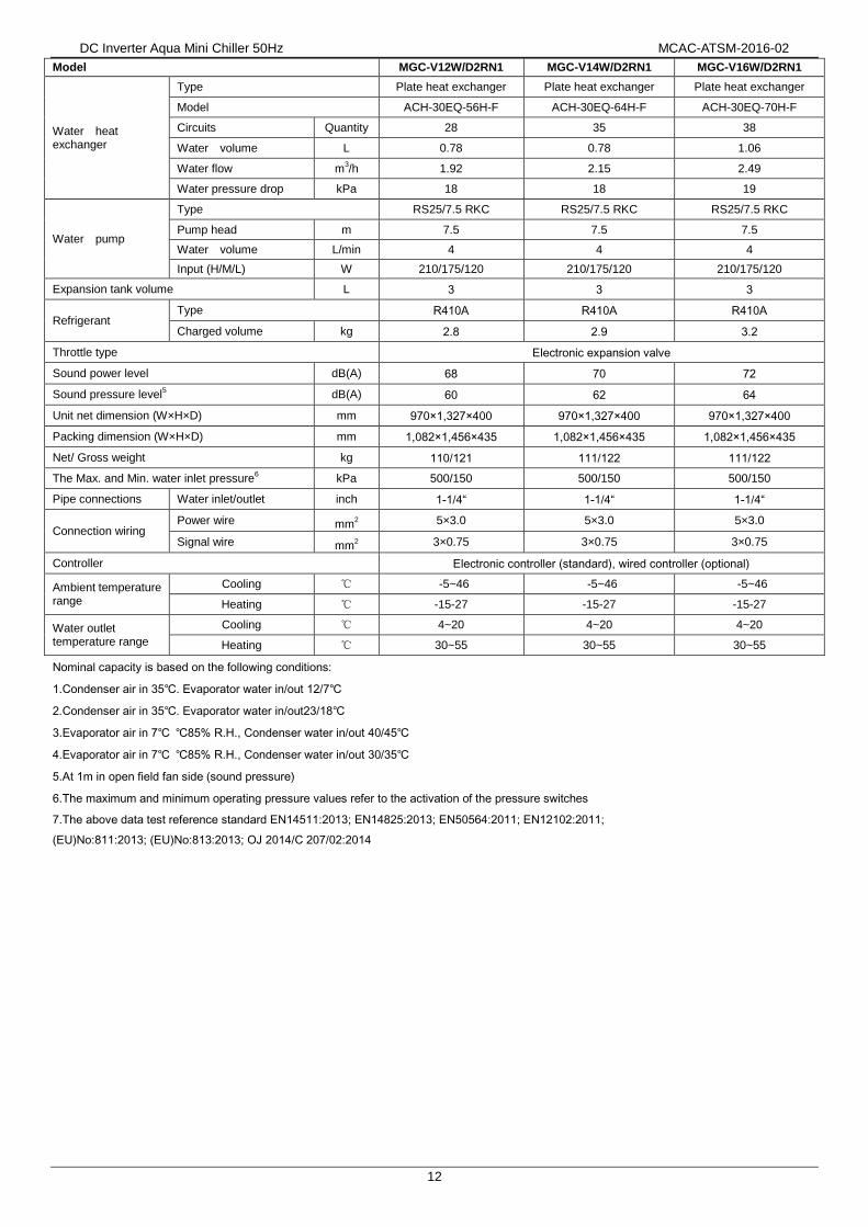
12
Model MGC-V12W/D2RN1 MGC-V14W/D2RN1 MGC-V16W/D2RN1
Water heat exchanger
Type Plate heat exchanger Plate heat exchanger Plate heat exchanger
Model ACH-30EQ-56H-F ACH-30EQ-64H-F ACH-30EQ-70H-F
Circuits Quantity 28 35 38
Water volume L 0.78 0.78 1.06
Water flow m3/h 1.92 2.15 2.49
Water pressure drop kPa 18 18 19
Water pump
Type RS25/7.5 RKC RS25/7.5 RKC RS25/7.5 RKC
Pump head m 7.5 7.5 7.5
Water volume L/min 4 4 4
Input (H/M/L) W 210/175/120 210/175/120 210/175/120
Expansion tank volume L 3 3 3
Refrigerant Type R410A R410A R410A
Charged volume kg 2.8 2.9 3.2
Throttle type Electronic expansion valve
Sound power level dB(A) 68 70 72
Sound pressure level5 dB(A) 60 62 64
Unit net dimension (W×H×D) mm 970×1,327×400 970×1,327×400 970×1,327×400
Packing dimension (W×H×D) mm 1,082×1,456×435 1,082×1,456×435 1,082×1,456×435
Net/ Gross weight kg 110/121 111/122 111/122
The Max. and Min. water inlet pressure6 kPa 500/150 500/150 500/150
Pipe connections Water inlet/outlet inch 1-1/4“ 1-1/4“ 1-1/4“
Connection wiring Power wire mm
2 5×3.0 5×3.0 5×3.0
Signal wire mm2 3×0.75 3×0.75 3×0.75
Controller Electronic controller (standard), wired controller (optional)
Ambient temperature range
Cooling ℃ -5~46 -5~46 -5~46
Heating ℃ -15-27 -15-27 -15-27
Water outlet temperature range
Cooling ℃ 4~20 4~20 4~20
Heating ℃ 30~55 30~55 30~55
Nominal capacity is based on the following conditions:
1.Condenser air in 35℃. Evaporator water in/out 12/7℃
2.Condenser air in 35℃. Evaporator water in/out23/18℃
3.Evaporator air in 7℃ ℃85% R.H., Condenser water in/out 40/45℃
4.Evaporator air in 7℃ ℃85% R.H., Condenser water in/out 30/35℃
5.At 1m in open field fan side (sound pressure)
6.The maximum and minimum operating pressure values refer to the activation of the pressure switches
7.The above data test reference standard EN14511:2013; EN14825:2013; EN50564:2011; EN12102:2011;
(EU)No:811:2013; (EU)No:813:2013; OJ 2014/C 207/02:2014

MCAC-ATSM-2016-02 DC Inverter Aqua Mini Chiller 50Hz
13
6. Dimensions
MGC-V5W/D2N1,MGC-V7W/D2N1 (Unit: mm)
MGC-V10W/D2N1,MGC-V12W/D2RN1,MGC-V14W/D2RN1,MGC-V16W/D2RN1 (Unit: mm)
1327
900970
600
34
8
32
0
40
03
60

DC Inverter Aqua Mini Chiller 50Hz MCAC-ATSM-2016-02
14
7. Refrigeran Cycle
MGC-V5W/D2N1,MGC-V7W/D2N1
MGC-V10W/D2N1, MGC-V12W/D2N1, MGC-V12W/D2RN1, MGC-V14W/D2RN1, MGC-V16W/D2RN1
HEAT PUMP
1 compressor
2 high pressure switch
3 4-way valve(only HEAP PUMP)
4 condenser
5 filter
6 electric expansive valve
7 liquid receiver
8 plate heat exchanger
9 defrost heater
10 water Temp. sensor
11 accumulater
12 low pressure switch
13 crankcase heater
LP
HP
1 3
10
2
4
67 75
8
11
9
12
13
14
15
16
16
15
1 compressor
2 4-Way Valve
3 accumulator
4 condenser
5 electronic expansion valve
6 liquid receive
7 filter
8 plate heat exchanger
9 differential pressure switch
10 high pressure switch11 low pressure switch
12 Temp. sensor (discharge)13 Temp. sensor (ambient)14 Temp. sensor (condenser)15 Temp. sensor (plate heat exchanger)16 water Temp. sensor

DC Inverter Aqua Mini Chiller 50HzMCAC-ATSM-2016-02
15
8. Wiring diagram
MGC-V5W/D2N1 & MGC-V7W/D2N1
CN10
1
U(R)
V(S)
W(C)
CT1
CN4
CN33
CN49
CN47
CN34
43
FAN
COMP
.
CN10
5
XS3
XP3
XS4
XP4
L_PR
O
F.S.
UV
P
N
P5
P6
P1
W
P2
P3
P4 AC
_IN
AC
_INP
-IN
L’
P_O
UT
N_O
UT
MA
IN C
ON
TR
OL
PA
NEL
EEV.
YELLOW
U
V W
Tin
T3 T4X
P2
P9
CN11
CN10
L N
BLACK
Y/G
PO
WE
R S
UP
PLY
RED
L’
P6P5
P-4
P-3
IPM
N -N
-
IPM
P+
P+
P-2
RY
1
CN29
XS2
Tout
Tb1
CN20
CN13
CN9
CN8
CN64
4-W
AY
CN62
CP_H
EAT
CN65
CRAN
K
CN66
S.V.
CN14
CN55
CN40
RED
WHITE
Y/G
BLUE
BROWN
REDY/G
RED
BLACK
BLACK
BLUE
RED
BLACK
YELLOW
CN100
PFC &
IPM
PA
NEL
Tp
DISP
LAY
BOAR
D
Dis
play
E9
H0
E4
E5
E6
EA
Eb
P2
P8
P1
P3
P4
P6
P5
Mal
func
tion
or P
rote
ctio
n
EE
PR
OM
mal
func
tion
Com
mun
icat
ion
mal
func
tion
betw
een
the
mai
n co
ntro
lling
chi
p an
d IP
DU
T3&
T4
tem
pera
ture
sen
sor
mal
func
tion
Vol
tage
pro
tect
ion
DC
fan
mot
or m
alfu
nctio
n
5-m
inut
e er
ror f
or h
eatin
g m
ode
fan
in a
rea
AH
igh
pres
sure
pro
tect
ion
Low
pre
ssur
e pr
otec
tion
Out
door
uni
ts c
urre
nt p
rote
ctio
n
Com
pres
sor
disc
harg
e te
mp.
Pro
tect
ion
Con
dens
er h
igh
tem
pera
ture
pro
tect
ion
IPM
mod
e pr
otec
tion
Typh
oon
prot
ectio
n
Two
times
of E
6 pr
otec
tion
in 1
0 m
inute
s
Rad
iato
r hi
gh te
mpe
ratu
re p
rote
ctio
nP
L
HH
Tin
tem
pera
ture
sen
sor
mal
func
tion
EC
Tout
tem
pera
ture
sen
sor
mal
func
tion
C0
Tb1
tem
pera
ture
sen
sor
mal
func
tion
C1
Tb2
tem
pera
ture
sen
sor
mal
func
tion
CL
CH
Low
wat
er te
mpe
ratu
re p
rote
ctio
n in
coo
ling
mod
e
Pb
Out
door
uni
ts a
nti-
free
zing
pro
tect
ion
CP
Plat
e H
eat E
xcha
nger
ant
i-fre
ezin
g pr
otec
tion
C8
Flo
w s
witc
h m
alfu
nctio
n
PH
Hig
h te
mpe
ratu
re p
rote
ctio
n in
hea
ting
mod
e
BLUE
Dis
play
Mal
func
tion
or P
rote
ctio
n
CO
DE
PA
RT
NA
ME
Com
pres
sor
CR
AN
K
CT1
XT
1
AC
cur
rent
det
ecto
r
4-W
AY
CO
MP.
EE
V.E
lect
ric E
xpan
sive
Val
veO
utdo
or fa
n m
otor
FAN
H-P
RO
L-P
RO
T3
T4
Tp
Com
pres
sor e
lect
ric
heat
ing
zone
Hig
h pr
essu
re s
witc
h
Low
pre
ssur
e sw
itch
PFC INDUCTANCE
4-W
ay v
alve
Con
dens
er t
empe
ratu
re s
enso
r
Out
door
am
bien
t tem
pera
ture
sen
sor
Com
p. D
isch
arge
tem
pera
ture
sen
sor
14-W
ay te
rmin
alXT1
CP
_HE
ATPl
ate
Hea
t Exc
hang
er e
lect
ric h
eatin
g zo
ne
FS
_HE
AT
Tb1 Tin
Tout
Pla
te h
ea
t exc
ha
ng
er
an
ti-f
ree
zin
g te
mp
era
ture
se
nso
r
Inle
t wat
er te
mpe
ratu
re s
enso
r of h
eat e
xcha
nger
Outle
t wa
ter
tem
pera
ture
sen
sor o
f hea
t exc
hang
er
SW
4
ON
12
SW
4
Without
rem
ote
contr
al fu
nction
PUMP
1
CN63
FS_H
EAT
CN53
CN32
CN25 T
RA
NS
T O
UT
TR
AN
ST
IN
TRAN
SFO
RM
ER
N
Hig
h in
let a
nd o
utle
t wat
er te
mp.
diff
eren
ce p
rote
ctio
n in
coo
ling
mod
e
Flow
sw
itch
elec
tric
heat
ing
zone
BLACK
RED
BROWN
BROWN
GREEN
12
43 5 6 87
Tb2
tem
p. V
alue(
Res
erve
d)
Tota
l ca
pa
city
re
qu
ire
me
nts
Th
e re
vise
d ca
pa
city
re
qu
ire
me
nts
Co
olin
g/h
ea
tin
g te
mp
. se
t
T3
tem
p. V
alue
T4
tem
p. V
alue
Tp
tem
p. V
alue
Fan
spe
ed0-
hutd
own,
1~7-
Fan
spe
edS
2
11
Tb1
tem
p. V
alue
0 9
Tin
tem
p. V
alue
1
Run
ning
mod
e0-
Shut
dow
n,1-
The
pum
p m
odel
,2-C
oolin
g,3-
Hea
ting,
4-Fo
rced
coo
ling.
10
Tout
tem
p. V
alue
Ch
eck
ing
No
.M
eani
ngs
The
nor
mal
dis
play
13 171614 15 18 19 20
T6
tem
p. V
alue(
Res
erve
d )
Out
door
uni
ts c
urre
nt
Pow
er s
uppl
y vo
ltage
AD
val
ue
EX
V o
peni
ng
Err
or
1
Mea
ning
s
20209049
0086
CN5
XS5
XP5
H_PR
O
Insu
lati
ng
she
ath
dFD
efr
ost
ing
d8R
em
ote
co
ntr
ol
Fre
qu
en
cy
Err
or
2
Err
or
3
Tem
p. S
enso
r cod
eTi
n/To
ut/
Tb1
/T3/
T4
B=4
100K
, R
℃=1
0kΩ
25/5
025
Tp
B=3
950K
, R
℃=5
kΩ25
/50
90
Pro
pe
rty
valu
es
Ch
eck
ing
No
.
A
BC
F.S
.F
low
sw
itch
DC
Filt
er P
AN
EL
EX_H
EAT
EX
_HE
ATE
xhau
st v
alve
ele
ctri
c he
atin
g zo
ne
BROWN
BROWN
BROWN
BROWN
BLUE
BLUE
BLUE
XP
1
XS1
NL
31
26
45
97
8GN
D10
11
CN31
RED
YELLOW
GRAY
BLACK
YELLOW Wire
con
trolle
r
1 2 3 4 5 6 7
8 9
10 11
+12V
ON/OF
FP
UM
P2
C/H
+12V
PQ
ER
EM
OT
E
ALA
RM
Remo
te co
oling
/heati
ngRe
mot
e sh
utdo
wn
"PU
MP
2" a
nd
wiri
ng te
rmin
al p
orts
pro
vide
on
ly th
e sw
itch
sign
al.T
he lo
ad s
houl
d be
con
trol
led
thro
ugh
the
AC
con
tact
or.
""
RE
MO
TE
ALA
RM
Ple
ase
use
3-co
re s
hiel
ded
wire
to c
onne
ct th
e w
and
the
shie
ldin
g la
yer
mus
t be
grou
nded
.ire
co
ntro
ller
NO
TE
Th
e w
ire
con
tro
ller
is o
pti
on
al.
N
BROWN
BROWN
BROWN
BROWN CN60
2
GREEN
With r
em
ote
contr
al fu
nction
SW
4
ON
12

DC Inverter Aqua Mini Chiller 50Hz MCAC-ATSM-2016-02
16
MGC-V10W/D2N1 & MGC-V12W/D2N1
"PU
MP
2" a
nd
wiri
ng te
rmin
al p
orts
pro
vide
on
ly th
e sw
itch
sign
al.T
he lo
ad s
houl
d be
con
trol
led
thro
ugh
the
AC
con
tact
or.
""
RE
MO
TE
ALA
RM
E9
H0
E4
E5
E6
EA
Eb
P2
P8
P1
P3
P4
P6
P5
EE
PR
OM
malfu
nct
ion
Com
munic
atio
n m
alfu
nct
ion b
etw
een
the m
ain
contr
olli
ng c
hip
and IP
DU
T3&
T4 tem
pera
ture
senso
r m
alfu
nct
ion
Volta
ge p
rote
ctio
n
DC
fan m
oto
r m
alfu
nct
ion
5-m
inut
e er
ror f
or h
eatin
g m
ode
fan
in a
rea
A
Hig
h p
ress
ure
pro
tect
ion
Low
pre
ssure
pro
tect
ion
Outd
oor
units
curr
ent pro
tect
ion
Com
pre
ssor
dis
charg
e tem
p. P
rote
ctio
n
Condense
r hig
h tem
pera
ture
pro
tect
ion
IPM
mode p
rote
ctio
n
Typ
hoon p
rote
ctio
n
Two
times
of E
6 pr
otec
tion
in 1
0 m
inut
es
Radia
tor
hig
h tem
pera
ture
pro
tect
ion
PL
C0
Tin
tem
pera
ture
senso
r m
alfu
nct
ion
C1
Tout te
mpera
ture
senso
r m
alfu
nct
ion
F7
Tb1 tem
pera
ture
senso
r m
alfu
nct
ion
F8
Tb2 tem
pera
ture
senso
r m
alfu
nct
ion
Pb
Ou
tdo
or
un
its
an
ti-f
ree
zin
g p
rote
cti
on
CP
Ant
i-idl
ing
prot
ectio
n of
wat
er p
ump
C8
Flo
w s
witc
h m
alfu
nct
ion
CH
Hig
h te
mp
era
ture
pro
tect
ion
in h
ea
tin
g m
od
e12
43 5 6 87
Tb2 tem
p. V
alu
e
To
tal c
ap
acit
y re
qu
ire
me
nts
Th
e r
evis
ed c
ap
acit
y re
qu
ire
me
nts
Co
olin
g/h
ea
tin
g t
em
p. se
t
T3 tem
p. V
alu
e
T4 tem
p. V
alu
e
Tp tem
p. V
alu
e
Fan s
peed
0-
hutd
ow
n,1
~7-F
an s
peed
S
2
11
Tb
1 t
em
p.
Va
lue
0 9
Tin
te
mp
. V
alu
e
1
Run
ning
mod
e0-
Shu
tdow
n,1-
The
pum
p m
odel
,2-C
oolin
g,3-
Hea
ting,
4-F
orce
d co
olin
g.
10
Tou
t te
mp
. V
alu
e
Ch
eckin
g N
o.
Meanin
gs
Th
e n
orm
al d
isp
lay
13
17
16
14
15
18
19
20
T6 tem
p. V
alu
e(
Rese
rved )
Outd
oor
units
curr
ent
Pow
er
supply
volta
ge A
D v
alu
e
EX
V o
pe
nin
g
Err
or
1
Meanin
gs
dF
De
fro
sti
ng
d8
Re
mo
te c
on
tro
l
Fre
qu
en
cy
Err
or
2
Err
or
3
Tem
p. S
en
sor
cod
eT
in/T
ou
t/T
b1
Tb
2/T
3/T
4B
=4
10
0K
,
R℃
=1
0kΩ
25
/50
25
Tp
B=
39
50
K ,
R
℃=
5kΩ
25
/50
90
Pro
pe
rty
va
lue
s
Ch
eckin
g N
o.
COMP.
UV
W
U
V W
20
20
90
4A
09
42
Y/G
MA
IN B
OA
RD
IPM
& P
FC
MO
DU
LE
Ple
ase
use
3-co
re s
hiel
ded
wire
to c
onne
ct th
e w
and
the
shie
ldin
g la
yer
mus
t be
grou
nded
.ire
co
ntro
ller
BLACK
RED
BLUE
XT1
PO
WE
R S
UP
PLY
Y/G
NLRED
BLACK
BLACK
Wire
con
trolle
rC
Y/G
12
34
31
26
45
97
8GND
GREEN
GREEN
BROWN
BROWN
To X
T1
WHITE
RED
GREEN
GREEN
BROWN
BROWN34
56
VU
W
1
2
3
4
5
6
7
8
9 1
0
11+1
2VON
/OFF
PU
MP
2
NO
TE
XT3
CO
DE
PA
RT
NA
ME
Com
pres
sor
CR
AN
K
CT1
XT
1
AC
cur
rent
det
ecto
r
4-W
AY
CO
MP.
EE
V.E
lect
ric E
xpan
sive
Val
ve
Out
door
fan
mot
orFA
N
H-P
RO
L-P
RO
T3
T4
Tp
Com
pres
sor e
lect
ric
heat
ing
zone
Hig
h pr
essu
re s
witc
h
Low
pre
ssur
e sw
itch
4-W
ay v
alve
Con
dens
er t
empe
ratu
re s
enso
r
Out
door
am
bien
t tem
pera
ture
sen
sor
Com
p. D
isch
arge
tem
pera
ture
sen
sor
XT
2,X
T3
14-W
ay te
rmin
al
CP
_HE
AT1
Plat
e H
eat E
xcha
nger
ele
ctric
hea
ting
zone
FS
_HE
AT
Tb1 Tin
Tout
Pla
te h
ea
t exc
ha
ng
er
an
ti-f
ree
zin
g te
mp
era
ture
se
nso
r 1
Inle
t wat
er te
mpe
ratu
re s
enso
r of h
eat e
xcha
nger
Out
let
wat
er t
empe
ratu
re s
enso
r of h
eat e
xcha
nger
Flow
sw
itch
elec
tric
heat
ing
zone
F.S
.F
low
sw
itch/
Exh
aust
val
ve
WIR
ING
DIA
GR
AM
(O
UT
DO
OR
UN
IT)
CAP1
,CAP
2C
AP
AC
ITO
R
PTC
1,PT
C2
L
KM
1AC
CO
NTA
CTO
R
THER
MAL
RES
ISTO
R
REA
CTO
R
R1,
R2
RE
SIS
TAN
CE
ZR1
Vol
tage
Dep
ende
nt R
esis
tor
3-W
ay te
rmin
al
Pla
te h
ea
t exc
ha
ng
er
an
ti-f
ree
zin
g te
mp
era
ture
se
nso
r 2
Tb2
CT
1
CN4
CN3
RES
CN1
CN2
CN30
CN11
Y/G
TRANS OUT
CN26
CN5
NU
VW
P_1
L_1
L_2N_1
VIN_N
P
CN6
TRANS IN
CN51T
R
CAP1
CAP2
A2
A1
A3
L_2
L_1
XT3
L_
OU
T
N_
OU
T
L_
IN
N_
IN
CN1
CN3
RE
D
FORC
ECO
OLCH
ECK
SW1
SW2
DIS1
CH2
Sw4
ON 12
CT
1
CH1
1 2 34 5
Z
REC
CH5
EX
_HE
AT
CN
32
CN
31
CN
34
CN
33
S.V
.
BROWN
BROWN
BLUE
BLUE
BLUE
BLUE
CP
_HE
AT1
FS
_HE
ATP
UM
P1
4-W
AYC
RA
NK
BROWN
BROWN
BROWN
BROWN
BROWN
BROWN
CN
35
CN
36
CN
38
CN
19
CN
17
5
FAN
-DO
WN
Y/G
FAN
-UP
Y/G
5
CN
41
CN
40
CN6
CN18
65
CN
5
CN
12
CN
8
CN
9T
4
T3
Tp H-P
RO
L-P
RO
CN
14
Tout
Tb1
Tin
Tb2
Diff
eren
tial P
ress
ure
Sw
itch
CN
15
DISP
LAY
BOAR
D EE
V.5
CN
22
RED
WHITE
12
RE
D
RE
D
BL
AC
KB
LA
CK
BL
AC
K
RE
D
BL
AC
K
YELLOW
YELLOW
BL
UE
YELLOW
YELLOW
BL
UE
BL
UE
BLU
E
BLU
E
RE
D
BL
AC
K
WH
ITE
BL
AC
K
EX
_HE
ATEx
haus
t val
ve e
lect
ric h
eatin
g zo
ne
d0
Oil
retu
rn o
f co
mp
resso
r
BLACK
RED
BLUE
BLACK
RED
BLUE
BLACK
BLUE
WHITE
Dis
pla
y
CL
Malfu
nct
ion o
r P
rote
ctio
nD
isp
lay
Malfu
nct
ion o
r P
rote
ctio
nL
ow
te
mp
era
ture
pro
tect
ion
in h
ea
tin
g m
od
e
A B C D
Th
e w
ire
con
tro
ller
is o
pti
on
al.
C/H
1011
+12V
PQ
ER
EM
OT
E
ALA
RM
Remo
te co
oling
/heati
ngRe
mot
e sh
utdo
wn
8 YELLOW
RED
78YELLOW
SW4
ON 12
Switc
h set
ting-
Mod
el se
lect
ion
SW4_1
SW4_2
ON
OFF
Rese
rved
With
out r
emot
e co
oling
/hea
ting
With
rem
ote
cooli
ng/h
eatin
g
Rese
rved

DC Inverter Aqua Mini Chiller 50HzMCAC-ATSM-2016-02
17
MGC-V12W/D2RN1, MGC-V14W/D2RN1 & MGC-V16W/D2RN1
E9
H0
E4
E5
E6
EA
Eb
P2
P8
P1
P3
P4
P6
P5
EE
PR
OM
ma
lfun
ctio
n
Co
mm
un
ica
tion
ma
lfun
ctio
n b
etw
ee
n
the
ma
in c
on
tro
llin
g c
hip
an
d I
PD
U
T3
&T
4 t
em
pe
ratu
re s
en
sor
ma
lfun
ctio
n
Vo
ltag
e p
rote
ctio
n
DC
fa
n m
oto
r m
alfu
nct
ion
5-m
inut
e er
ror f
or h
eatin
g m
ode
fan
in a
rea
A
Hig
h p
ress
ure
pro
tect
ion
Lo
w p
ress
ure
pro
tect
ion
Ou
tdo
or
un
its c
urr
en
t p
rote
ctio
n
Com
pres
sor
disc
harg
e te
mp.
Pro
tect
ion
Co
nd
en
ser
hig
h t
em
pe
ratu
re p
rote
ctio
n
IPM
mo
de
pro
tect
ion
Typ
ho
on
pro
tect
ion
Two
times
of E
6 pr
otec
tion
in 1
0 m
inut
es
Ra
dia
tor
hig
h t
em
pe
ratu
re p
rote
ctio
nP
L
C0
Tin
tem
pera
ture
senso
r m
alfu
nct
ion
C1
Tout te
mpera
ture
senso
r m
alfu
nct
ion
F7
Tb1 tem
pera
ture
senso
r m
alfu
nct
ion
F8
Tb2 tem
pera
ture
senso
r m
alfu
nct
ion
Pb
Ou
tdo
or
un
its
an
ti-f
ree
zin
g p
rote
ctio
n
CP
C8
Flo
w s
witc
h m
alfu
nct
ion
CH
Hig
h te
mpe
ratu
re p
rote
ctio
n in
hea
ting
mod
e
Dis
pla
yM
alfu
nct
ion
or
Pro
tect
ion
CO
DE
PA
RT
NA
ME
Com
pres
sor
CR
AN
K
CT1
XT
1
AC
cur
rent
det
ecto
r
4-W
AY
CO
MP.
EE
V.E
lect
ric E
xpan
sive
Val
ve
Out
door
fan
mot
orFA
N
H-P
RO
L-P
RO
T3
T4
Tp
Com
pres
sor e
lect
ric
heat
ing
zone
Hig
h pr
essu
re s
witc
h
Low
pre
ssur
e sw
itch
4-W
ay v
alve
Con
dens
er t
empe
ratu
re s
enso
r
Out
door
am
bien
t tem
pera
ture
sen
sor
Com
p. D
isch
arge
tem
pera
ture
sen
sor
XT
2
14-W
ay te
rmin
al
2-W
ay te
rmin
al
CP
_HE
AT1
Plat
e H
eat E
xcha
nger
ele
ctric
hea
ting
zone
FS
_HE
AT
Tb1 Tin
Tout
Pla
te h
ea
t exc
ha
ng
er
an
ti-f
ree
zin
g te
mp
era
ture
se
nso
r 1
Inle
t wat
er te
mpe
ratu
re s
enso
r of h
eat e
xcha
nger
Out
let
wat
er t
empe
ratu
re s
enso
r of h
eat e
xcha
nger
Flow
sw
itch
elec
tric
heat
ing
zone
12
43 5 6 87
Tb
2 t
em
p.
Va
lue
To
tal c
ap
ac
ity
req
uir
em
en
ts
Th
e r
ev
ise
d c
ap
ac
ity
req
uir
em
en
ts
Co
oli
ng
/he
ati
ng
te
mp
. s
et
T3
te
mp
. V
alu
e
T4
te
mp
. V
alu
e
Tp
te
mp
. V
alu
e
Fa
n s
pe
ed
0-
hu
tdo
wn
,1~
7-F
an
sp
ee
dS
2
11T
b1
te
mp
. V
alu
e
0 9
Tin
tem
p. V
alue
1
Run
ning
mod
e0-
Shu
tdow
n,1-
The
pum
p m
odel
,2-C
oolin
g,3-
Hea
ting,
4-Fo
rced
coo
ling.
10
Tou
t te
mp
. V
alu
e
Ch
eckin
g N
o.
Me
an
ing
s
Th
e n
orm
al d
isp
lay
13
17
1614
15
18
19
20
T6
te
mp
. V
alu
e(
Re
serv
ed
)
Ou
tdo
or
un
its c
urr
en
t
Po
we
r su
pp
ly v
olta
ge
AD
va
lue
EX
V o
peni
ng
Err
or
1
Me
an
ing
s
dF
De
fro
sti
ng
d8
Re
mo
te c
on
tro
l
Fre
qu
en
cy
Err
or
2
Err
or
3Te
mp.
Sen
sor c
ode
Tin
/Tou
t/T
b1/T
3/T
4B
=41
00K
, R
℃=
10kΩ
25/5
025
Tp
B=
3950
K ,
R℃
=5kΩ
25/5
090
Pro
pe
rty
valu
es
Ch
eckin
g N
o.
F.S
.F
low
sw
itch
COMP.
UV
WU
V W
20
20
90
49
00
66
CA
P1
R2
EX
_HE
AT
BLUEY/
G
Y/G
CN
47
CN
31
CN
33
CN
32
S.V
.
CN
17
IC2
01
CN
20
5
CN
19
DIS1
CN
50
CN
5
CN
6
CN
1
CN
9
EE
V.
CN
22
5C
N201
T4
T3
Tp H-P
RO
L-P
RO
A2
A1
OR
AN
GE
54
~~~1 2 3
D1
R1
CA
P2
FAN
-DO
WN
Y/G
FAN
-UP
Y/G
10
5
CN70
CN71BLU
EB
RO
WN
SW3
ON 12
2
WIR
ING
DIA
GR
AM
(O
UT
DO
OR
UN
IT)
CN
36L1
GN
D_2
CN
36L1
CN
37L2
CN
38L3
CN
30
CN
31
CN
32
L1’
L2’
L3’
CN
19
CN
18
GN
D_1
CN
39
N
POW
ER &
FIL
TER
BO
ARD
MA
IN B
OA
RD
UV
W
CN
2C
N1
PN
CN
5
IPM
MO
DU
LE
BLU
E
WH
ITE
(BR
OW
N)
RE
D
BROWN
RE
D(B
RO
WN
)
RE
D
Y/G
BLA
CK
WH
ITE
BLA
CK
ZR
1
RE
D
RED
RE
D
BLA
CK
BLA
CK
RE
D
BLA
CKBLU
E
BROWN
BLUE
BLUE
BLUE
BLACK
RE
D
BLACK
RED
BLUE
2
OR
AN
GE
RE
D
L
BLA
CK
RE
D
RE
D
RE
DR
ED
CT1
BLU
ECT1
2
IC20
1C
N2
50
XT1
PO
WE
R S
UP
PLY
Y/G
AB
NC
RED
WHITE
BLUE
BLACK
BLAC
K
BLACK
BLUE
WHITE
CY
/G
BLA
CK
RE
D
BLU
E(B
RO
WN
)
BLU
E
RE
D
ZCA
P1,C
AP2
CA
PA
CIT
OR
PTC
1,PT
C2
L
KM
1AC
CO
NTA
CTO
R
THER
MAL
RES
ISTO
R
REA
CTO
R
R1,
R2
RE
SIS
TAN
CE
ZR1
Vol
tage
Dep
ende
nt R
esis
tor
PT
C1
PT
C2
KM1
2221
A1
6
A2
T
T
BROWN
BROWN
24
5 13
RE
DB
LUE
BLA
CK
CN
14
Tout
Tb1
Tin
Tb2
Diff
eren
tial P
ress
ure
Sw
itch
BLUE
CP
_HE
AT1
FS
_HE
ATP
UM
P1
4-W
AYC
RA
NK
BROWN
BROWN
BROWN
BROWN
BROWN
BROWN
12
34
CN
34
CN
35
CN
49
CN
38
CN
37
CN
40
GND
CN
20
DISP
LAY
BOAR
D
GREEN
GREEN
BROWN
BROWN
XT1
WHITE
RED
GREEN
GREEN
BROWN
BROWN
12
34
4
XT2
VU
W
NO
TE
XT3
XT
33-
Way
term
inal
Pla
te h
ea
t exc
ha
ng
er
an
ti-f
ree
zin
g te
mp
era
ture
se
nso
r 2
Tb2
CN
30
3
5
EX
_HE
ATEx
haus
t val
ve e
lect
ric h
eatin
g zo
ne
Ant
i-idl
ing
prot
ectio
n of
wat
er p
ump
d0
Oil
retu
rn o
f co
mp
resso
r
Ple
ase
use
3-co
re s
hiel
ded
wire
to c
onne
ct w
,an
d th
e sh
ield
ing
laye
r mus
t be
grou
nded
.ire
con
trolle
r
RED
BLACK
CL
Lo
w t
em
pe
ratu
re p
rote
ctio
n in
he
ati
ng
mo
de
Dis
pla
yM
alfu
nct
ion
or
Pro
tect
ion
A B C D
The
wir
e co
ntro
ller i
s op
tiona
l.3
12
64
59
78
1011
Wire
con
trolle
r
1 2 3 4 5 6 7
8 9
10 11
+12V
ON/OF
FP
UM
P2
C/H
+12V
PQ
ER
EM
OT
E
ALA
RM
Remo
te co
oling
/heati
ngRe
mot
e sh
utdo
wn
"PU
MP
2" a
nd
wiri
ng te
rmin
al
ports
pro
vide
onl
y th
e sw
itch
sign
al.
The
load
sho
uld
be c
ontro
lled
thro
ugh
the
AC
con
tact
or.
""
RE
MO
TE A
LAR
M
YELLOW
RED
SW3
ON
12
Switc
h set
ting-
Mod
el se
lect
ion
SW3_1
SW3_2
ON
OFF
Rese
rved
With
out r
emot
e co
oling
/hea
ting
With
rem
ote
cooli
ng/h
eatin
g
Rese
rved

DC Inverter Aqua Mini Chiller 50Hz MCAC-ATSM-2016-02
18
9. Electric Characteristics
Model Outdoor Unit Power Supply Compressor OFM
Hz Voltage Phase Min. Max. MCA TOCA MFA MSC RLA kW FLA
MGC-V5W/D2N1 50Hz 220~240V 1Ph 198V 264V 10.1 14.6 20 29.5 8.1 0.17 1.65
MGC-V7W/D2N1 50Hz 220~240V 1Ph 198V 264V 10.1 15.6 20 29.5 8.1 0.17 1.65
MGC-V10W/D2N1 50Hz 220~240V 1Ph 198V 264V 15.1 26.0 30 52 12.1 0.20 1.8
MGC-V12W/D2N1 50Hz 220~240V 1Ph 198V 264V 15.1 25.0 30 52 12.1 0.20 1.8
MGC-V12W/D2RN1 50Hz 380~415V 3Ph 342V 456V 8.6 8.9 15 44 6.9 0.20 1.8
MGC-V14W/D2RN1 50Hz 380~415V 3Ph 342V 456V 8.6 9.6 15 44 6.9 0.20 1.8
MGC-V16W/D2RN1 50Hz 380~415V 3Ph 342V 456V 8.6 10.1 15 44 6.9 0.20 1.8
Remark:
MCA: Min. Current Amps. (A)
TOCA: Total Over-current Amps. (A)
MFA: Max. Fuse Amps. (A)
MSC: Max. Starting Amps. (A)
RLA: Rated Current Amps. (A)
OFM: Outdoor Fan Motor
FLA: Full Load Amps. (A)
kW: Rated Motor Output (kW)
MCAC-ATSM-2016-02 DC Inverter Aqua Mini Chiller 50Hz
19
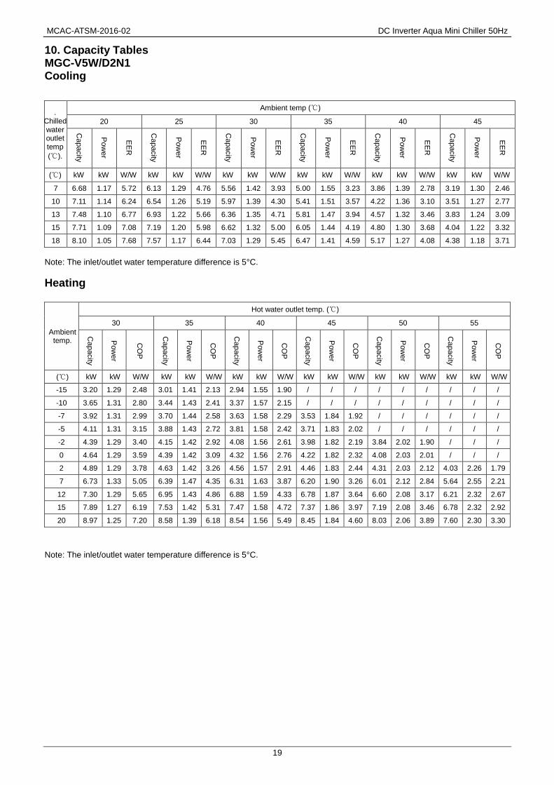
10. Capacity Tables MGC-V5W/D2N1
Cooling
. Chilled water outlet temp
(℃).
Ambient temp (℃)
20 25 30 35 40 45
Capacity
Pow
er
EE
R
Capacity
Pow
er
EE
R
Capacity
Pow
er
EE
R
Capacity
Pow
er
EE
R
Capacity
Pow
er
EE
R
Capacity
Pow
er
EE
R
(℃) kW kW W/W kW kW W/W kW kW W/W kW kW W/W kW kW W/W kW kW W/W
7 6.68 1.17 5.72 6.13 1.29 4.76 5.56 1.42 3.93 5.00 1.55 3.23 3.86 1.39 2.78 3.19 1.30 2.46
10 7.11 1.14 6.24 6.54 1.26 5.19 5.97 1.39 4.30 5.41 1.51 3.57 4.22 1.36 3.10 3.51 1.27 2.77
13 7.48 1.10 6.77 6.93 1.22 5.66 6.36 1.35 4.71 5.81 1.47 3.94 4.57 1.32 3.46 3.83 1.24 3.09
15 7.71 1.09 7.08 7.19 1.20 5.98 6.62 1.32 5.00 6.05 1.44 4.19 4.80 1.30 3.68 4.04 1.22 3.32
18 8.10 1.05 7.68 7.57 1.17 6.44 7.03 1.29 5.45 6.47 1.41 4.59 5.17 1.27 4.08 4.38 1.18 3.71
Note: The inlet/outlet water temperature difference is 5°C.
Heating
Ambient temp.
Hot water outlet temp. (℃)
30 35 40 45 50 55
Capacity
Pow
er
CO
P
Capacity
Pow
er
CO
P
Capacity
Pow
er
CO
P
Capacity
Pow
er
CO
P
Capacity
Pow
er
CO
P
Capacity
Pow
er
CO
P
(℃) kW kW W/W kW kW W/W kW kW W/W kW kW W/W kW kW W/W kW kW W/W
-15 3.20 1.29 2.48 3.01 1.41 2.13 2.94 1.55 1.90 / / / / / / / / /
-10 3.65 1.31 2.80 3.44 1.43 2.41 3.37 1.57 2.15 / / / / / / / / /
-7 3.92 1.31 2.99 3.70 1.44 2.58 3.63 1.58 2.29 3.53 1.84 1.92 / / / / / /
-5 4.11 1.31 3.15 3.88 1.43 2.72 3.81 1.58 2.42 3.71 1.83 2.02 / / / / / /
-2 4.39 1.29 3.40 4.15 1.42 2.92 4.08 1.56 2.61 3.98 1.82 2.19 3.84 2.02 1.90 / / /
0 4.64 1.29 3.59 4.39 1.42 3.09 4.32 1.56 2.76 4.22 1.82 2.32 4.08 2.03 2.01 / / /
2 4.89 1.29 3.78 4.63 1.42 3.26 4.56 1.57 2.91 4.46 1.83 2.44 4.31 2.03 2.12 4.03 2.26 1.79
7 6.73 1.33 5.05 6.39 1.47 4.35 6.31 1.63 3.87 6.20 1.90 3.26 6.01 2.12 2.84 5.64 2.55 2.21
12 7.30 1.29 5.65 6.95 1.43 4.86 6.88 1.59 4.33 6.78 1.87 3.64 6.60 2.08 3.17 6.21 2.32 2.67
15 7.89 1.27 6.19 7.53 1.42 5.31 7.47 1.58 4.72 7.37 1.86 3.97 7.19 2.08 3.46 6.78 2.32 2.92
20 8.97 1.25 7.20 8.58 1.39 6.18 8.54 1.56 5.49 8.45 1.84 4.60 8.03 2.06 3.89 7.60 2.30 3.30
Note: The inlet/outlet water temperature difference is 5°C.

DC Inverter Aqua Mini Chiller 50Hz MCAC-ATSM-2016-02
20
MGC-V7W/D2N1 Cooling
. Chilled water outlet temp
(℃).
Ambient temp (℃)
20 25 30 35 40 45
Capacity
Pow
er
EE
R
Capacity
Pow
er
EE
R
Capacity
Pow
er
EE
R
Capacity
Pow
er
EE
R
Capacity
Pow
er
EE
R
Capacity
Pow
er
EE
R
(℃) kW kW W/W kW kW W/W kW kW W/W kW kW W/W kW kW W/W kW kW W/W
7 9.69 2.09 4.64 8.84 2.13 4.14 7.93 2.18 3.63 7.00 2.25 3.11 4.52 1.75 2.58 3.03 1.45 2.10
10 10.48 2.05 5.11 9.57 2.08 4.60 8.59 2.13 4.03 7.60 2.19 3.47 5.08 1.71 2.96 3.57 1.43 2.50
13 11.31 2.00 5.66 10.35 2.02 5.11 9.27 2.07 4.47 8.21 2.13 3.85 5.69 1.69 3.37 4.18 1.42 2.94
15 11.87 1.97 6.04 10.87 1.99 5.46 9.74 2.03 4.79 8.63 2.09 4.13 6.12 1.66 3.68 4.61 1.41 3.28
18 12.78 1.92 6.67 11.41 1.94 5.88 10.51 1.97 5.32 9.30 2.03 4.57 6.82 1.63 4.18 5.33 1.39 3.84
Note: The inlet/outlet water temperature difference is 5°C.
Heating
Ambient temp.
Hot water outlet temp. (℃)
30 35 40 45 50 55
Capacity
Pow
er
CO
P
Capacity
Pow
er
CO
P
Capacity
Pow
er
CO
P
Capacity
Pow
er
CO
P
Capacity
Pow
er
CO
P
Capacity
Pow
er
CO
P
(℃) kW kW W/W kW kW W/W kW kW W/W kW kW W/W kW kW W/W kW kW W/W
-15 4.13 1.70 2.43 3.88 1.86 2.09 3.80 2.04 1.86 / / / / / / / / /
-10 4.71 1.72 2.74 4.44 1.88 2.37 4.35 2.07 2.10 / / / / / / / / /
-7 5.06 1.73 2.93 4.78 1.89 2.53 4.68 2.08 2.25 4.56 2.42 1.88 / / / / / /
-5 5.30 1.72 3.09 5.01 1.88 2.66 4.91 2.07 2.37 4.79 2.41 1.98 / / / / / /
-2 5.67 1.70 3.33 5.35 1.87 2.87 5.26 2.05 2.56 5.14 2.39 2.15 4.95 2.66 1.86 / / /
0 5.99 1.70 3.52 5.66 1.87 3.03 5.57 2.06 2.71 5.45 2.40 2.27 5.26 2.67 1.97 / / /
2 6.31 1.70 3.71 5.97 1.87 3.20 5.88 2.06 2.85 5.76 2.40 2.40 5.56 2.67 2.08 5.20 2.97 1.75
7 8.68 1.75 4.96 8.24 1.93 4.26 8.14 2.15 3.79 8.00 2.50 3.20 7.75 2.79 2.78 7.27 3.35 2.17
12 9.42 1.70 5.54 8.96 1.88 4.77 8.88 2.09 4.25 8.75 2.45 3.56 8.52 2.74 3.11 8.01 3.06 2.62
15 10.19 1.68 6.07 9.71 1.87 5.21 9.64 2.08 4.62 9.52 2.45 3.89 9.27 2.73 3.39 8.75 3.05 2.87
20 11.58 1.64 7.06 11.07 1.83 6.06 11.02 2.05 5.38 10.91 2.42 4.51 10.36 2.71 3.82 9.80 3.03 3.24
Note: The inlet/outlet water temperature difference is 5°C.

MCAC-ATSM-2016-02 DC Inverter Aqua Mini Chiller 50Hz
21
MGC-V10W/D2N1 Cooling
. Chilled water outlet temp
(℃).
Ambient temp (℃)
20 25 30 35 40 45
Capacity
Pow
er
EE
R
Capacity
Pow
er
EE
R
Capacity
Pow
er
EE
R
Capacity
Pow
er
EE
R
Capacity
Pow
er
EE
R
Capacity
Pow
er
EE
R
(℃) kW kW W/W kW kW W/W kW kW W/W kW kW W/W kW kW W/W kW kW W/W
7 11.08 2.23 4.97 10.99 2.45 4.49 10.62 2.68 3.97 10.00 2.95 3.39 9.16 3.25 2.82 8.14 3.57 2.28
10 11.77 2.25 5.22 11.66 2.47 4.72 11.27 2.72 4.15 10.61 2.99 3.55 9.73 3.29 2.95 8.65 3.62 2.39
13 12.93 2.28 5.67 12.81 2.50 5.12 12.38 2.75 4.50 11.66 3.03 3.85 10.70 3.33 3.21 9.39 3.79 2.48
15 13.74 2.29 5.99 13.61 2.52 5.40 13.15 2.77 4.74 12.39 3.05 4.06 11.37 3.37 3.38 9.73 3.70 2.63
18 15.17 2.32 6.54 14.66 2.55 5.75 13.87 2.81 4.94 12.85 3.09 4.15 11.61 3.41 3.40 9.85 3.41 2.89
Note: The inlet/outlet water temperature difference is 5°C.
Heating
Ambient temp.
Hot water outlet temp. (℃)
30 35 40 45 50 55
Capacity
Pow
er
CO
P
Capacity
Pow
er
CO
P
Capacity
Pow
er
CO
P
Capacity
Pow
er
CO
P
Capacity
Pow
er
CO
P
Capacity
Pow
er
CO
P
(℃) kW kW W/W kW kW W/W kW kW W/W kW kW W/W kW kW W/W kW kW W/W
-15 5.68 2.13 2.66 5.33 2.33 2.29 5.22 2.56 2.04 / / / / / / / / /
-10 6.48 2.16 3.00 6.10 2.36 2.59 5.98 2.60 2.30 / / / / / / / / /
-7 6.96 2.17 3.20 6.57 2.37 2.77 6.44 2.62 2.46 6.26 3.05 2.06 / / / / / /
-5 7.29 2.16 3.38 6.88 2.36 2.92 6.76 2.60 2.60 6.58 3.03 2.17 / / / / / /
-2 7.79 2.13 3.65 7.36 2.34 3.14 7.24 2.58 2.80 7.06 3.01 2.35 6.81 3.34 2.04 / / /
0 8.23 2.13 3.86 7.78 2.34 3.32 7.66 2.59 2.96 7.49 3.01 2.49 7.23 3.35 2.16 / / /
2 8.67 2.13 4.06 8.21 2.34 3.50 8.09 2.59 3.12 7.91 3.02 2.62 7.65 3.36 2.28 7.14 3.73 1.92
7 11.94 2.20 5.43 11.33 2.43 4.67 11.19 2.69 4.15 11.00 3.14 3.50 10.66 3.50 3.04 10.00 4.21 2.37
12 12.95 2.13 6.07 12.33 2.36 5.22 12.21 2.63 4.65 12.03 3.08 3.90 11.71 3.44 3.40 11.02 3.84 2.87
15 14.01 2.11 6.65 13.36 2.34 5.70 13.26 2.62 5.06 13.08 3.07 4.26 12.75 3.43 3.71 12.03 3.83 3.14
20 15.92 2.06 7.73 15.22 2.30 6.63 15.15 2.57 5.89 15.00 3.04 4.94 14.24 3.41 4.18 13.48 3.80 3.54
Note: The inlet/outlet water temperature difference is 5°C.

DC Inverter Aqua Mini Chiller 50Hz MCAC-ATSM-2016-02
22
MGC-V12W/D2N1 Cooling
. Chilled water outlet temp
(℃).
Ambient temp (℃)
20 25 30 35 40 45
Capacity
Pow
er
EE
R
Capacity
Pow
er
EE
R
Capacity
Pow
er
EE
R
Capacity
Pow
er
EE
R
Capacity
Pow
er
EE
R
Capacity
Pow
er
EE
R
(℃) kW kW W/W kW kW W/W kW kW W/W kW kW W/W kW kW W/W kW kW W/W
7 12.41 2.65 4.69 12.31 2.90 4.24 11.89 3.18 3.74 11.20 3.50 3.20 10.26 3.85 2.66 9.12 4.24 2.15
10 13.18 2.67 4.93 13.06 2.93 4.46 12.62 3.22 3.91 11.88 3.55 3.35 10.90 3.91 2.79 9.69 4.30 2.25
13 14.48 2.70 5.36 14.35 2.97 4.83 13.87 3.26 4.25 13.06 3.59 3.63 11.98 3.96 3.03 10.52 4.50 2.34
15 15.39 2.72 5.65 15.24 2.99 5.10 14.73 3.29 4.47 13.88 3.62 3.83 12.73 3.99 3.19 10.90 4.39 2.48
18 16.99 2.75 6.18 16.42 3.03 5.43 15.53 3.33 4.67 14.39 3.67 3.92 13.00 4.05 3.21 11.03 4.05 2.72
Note: The inlet/outlet water temperature difference is 5°C.
Heating
Ambient temp.
Hot water outlet temp. (℃)
30 35 40 45 50 55
Capacity
Pow
er
CO
P
Capacity
Pow
er
CO
P
Capacity
Pow
er
CO
P
Capacity
Pow
er
CO
P
Capacity
Pow
er
CO
P
Capacity
Pow
er
CO
P
(℃) kW kW W/W kW kW W/W kW kW W/W kW kW W/W kW kW W/W kW kW W/W
-15 6.35 2.57 2.47 5.96 2.81 2.12 5.84 3.08 1.89 / / / / / / / / /
-10 7.25 2.60 2.79 6.83 2.84 2.41 6.69 3.13 2.14 / / / / / / / / /
-7 7.79 2.62 2.98 7.34 2.85 2.57 7.20 3.15 2.28 7.00 3.67 1.91 / / / / / /
-5 8.16 2.60 3.14 7.70 2.84 2.71 7.55 3.13 2.41 7.36 3.65 2.02 / / / / / /
-2 8.71 2.57 3.39 8.23 2.82 2.92 8.09 3.11 2.60 7.90 3.62 2.18 7.62 4.02 1.89 / / /
0 9.21 2.57 3.58 8.70 2.82 3.08 8.57 3.11 2.75 8.37 3.63 2.31 8.08 4.03 2.01 / / /
2 9.70 2.57 3.77 9.18 2.82 3.25 9.04 3.12 2.90 8.85 3.63 2.44 8.55 4.04 2.12 7.99 4.49 1.78
7 13.35 2.65 5.04 12.67 2.92 4.34 12.51 3.24 3.86 12.30 3.78 3.25 11.92 4.21 2.83 11.18 5.07 2.20
12 14.48 2.57 5.64 13.78 2.84 4.85 13.66 3.16 4.32 13.45 3.71 3.63 13.09 4.15 3.16 12.32 4.63 2.66
15 15.66 2.54 6.18 14.94 2.82 5.30 14.82 3.15 4.70 14.63 3.70 3.95 14.26 4.13 3.45 13.45 4.61 2.92
20 17.80 2.48 7.18 17.02 2.76 6.16 16.94 3.09 5.47 16.77 3.65 4.59 15.92 4.10 3.88 15.07 4.58 3.29
Note: The inlet/outlet water temperature difference is 5°C.

MCAC-ATSM-2016-02 DC Inverter Aqua Mini Chiller 50Hz
23
MGC-V12W/D2RN1
Cooling
. Chilled water outlet temp
(℃).
Ambient temp (℃)
20 25 30 35 40 45
Capacity
Pow
er
EE
R
Capacity
Pow
er
EE
R
Capacity
Pow
er
EE
R
Capacity
Pow
er
EE
R
Capacity
Pow
er
EE
R
Capacity
Pow
er
EE
R
(℃) kW kW W/W kW kW W/W kW kW W/W kW kW W/W kW kW W/W kW kW W/W
7 12.41 2.56 4.86 12.31 2.80 4.39 11.89 3.07 3.88 11.20 3.38 3.31 10.26 3.72 2.76 9.12 4.09 2.23
10 13.18 2.58 5.10 13.06 2.83 4.61 12.62 3.11 4.05 11.88 3.43 3.47 10.90 3.77 2.89 9.69 4.15 2.33
13 14.48 2.61 5.55 14.35 2.87 5.00 13.87 3.15 4.40 13.06 3.47 3.76 11.98 3.82 3.14 10.52 4.34 2.42
15 15.39 2.63 5.85 15.24 2.89 5.28 14.73 3.18 4.63 13.88 3.50 3.97 12.73 3.86 3.30 10.90 4.24 2.57
18 16.99 2.66 6.40 16.42 2.92 5.62 15.53 3.22 4.83 14.39 3.54 4.06 13.00 3.91 3.32 11.03 3.91 2.82
Note: The inlet/outlet water temperature difference is 5°C.
Heating
Ambient temp.
Hot water outlet temp. (℃)
30 35 40 45 50 55
Capacity
Pow
er
CO
P
Capacity
Pow
er
CO
P
Capacity
Pow
er
CO
P
Capacity
Pow
er
CO
P
Capacity
Pow
er
CO
P
Capacity
Pow
er
CO
P
(℃) kW kW W/W kW kW W/W kW kW W/W kW kW W/W kW kW W/W kW kW W/W
-15 6.35 2.53 2.51 5.96 2.76 2.16 5.84 3.03 1.92 / / / / / / / / /
-10 7.25 2.56 2.83 6.83 2.79 2.44 6.69 3.08 2.17 / / / / / / / / /
-7 7.79 2.57 3.02 7.34 2.81 2.61 7.20 3.10 2.32 7.00 3.61 1.94 / / / / / /
-5 8.16 2.56 3.19 7.70 2.80 2.75 7.55 3.08 2.45 7.36 3.59 2.05 / / / / / /
-2 8.71 2.53 3.45 8.23 2.78 2.96 8.09 3.06 2.65 7.90 3.56 2.22 7.62 3.96 1.93 / / /
0 9.21 2.53 3.64 8.70 2.78 3.13 8.57 3.06 2.80 8.37 3.57 2.35 8.08 3.97 2.04 / / /
2 9.70 2.53 3.83 9.18 2.78 3.31 9.04 3.07 2.95 8.85 3.57 2.48 8.55 3.98 2.15 7.99 4.42 1.81
7 13.35 2.61 5.12 12.67 2.88 4.40 12.51 3.19 3.92 12.30 3.72 3.31 11.92 4.15 2.87 11.18 4.99 2.24
12 14.48 2.53 5.73 13.78 2.80 4.93 13.66 3.11 4.39 13.45 3.65 3.68 13.09 4.08 3.21 12.32 4.55 2.71
15 15.66 2.49 6.28 14.94 2.78 5.38 14.82 3.10 4.78 14.63 3.64 4.02 14.26 4.07 3.50 13.45 4.54 2.96
20 17.80 2.44 7.30 17.02 2.72 6.26 16.94 3.05 5.56 16.77 3.60 4.66 15.92 4.03 3.95 15.07 4.51 3.34
Note: The inlet/outlet water temperature difference is 5°C.

DC Inverter Aqua Mini Chiller 50Hz MCAC-ATSM-2016-02
24
MGC-V14W/D2RN1 Cooling
. Chilled water outlet temp
(℃).
Ambient temp (℃)
20 25 30 35 40 45
Capacity
Pow
er
EE
R
Capacity
Pow
er
EE
R
Capacity
Pow
er
EE
R
Capacity
Pow
er
EE
R
Capacity
Pow
er
EE
R
Capacity
Pow
er
EE
R
(℃) kW kW W/W kW kW W/W kW kW W/W kW kW W/W kW kW W/W kW kW W/W
7 13.87 2.97 4.66 13.75 3.24 4.24 13.29 3.55 3.75 12.50 3.90 3.21 11.08 3.74 2.96 9.81 4.12 2.38
10 14.92 3.02 4.94 14.79 3.29 4.49 14.28 3.61 3.96 13.43 3.97 3.39 11.92 3.81 3.13 10.56 4.19 2.52
13 16.38 3.07 5.34 16.23 3.35 4.84 15.68 3.68 4.27 14.75 4.04 3.65 13.09 3.87 3.38 10.95 4.25 2.58
15 17.39 3.10 5.60 17.23 3.39 5.08 16.64 3.72 4.47 15.66 4.08 3.84 13.91 3.91 3.55 11.35 4.15 2.74
18 18.92 3.15 6.00 18.28 3.45 5.30 17.29 3.78 4.57 15.99 4.15 3.85 13.99 3.98 3.52 11.49 3.83 3.00
Note: The inlet/outlet water temperature difference is 5°C.
Heating
Ambient temp.
Hot water outlet temp. (℃)
30 35 40 45 50 55
Capacity
Pow
er
CO
P
Capacity
Pow
er
CO
P
Capacity
Pow
er
CO
P
Capacity
Pow
er
CO
P
Capacity
Pow
er
CO
P
Capacity
Pow
er
CO
P
(℃) kW kW W/W kW kW W/W kW kW W/W kW kW W/W kW kW W/W kW kW W/W
-15 7.43 3.02 2.46 7.16 3.28 2.18 6.92 3.59 1.93 / / / / / / / / /
-10 8.43 3.06 2.75 8.10 3.34 2.43 7.79 3.65 2.13 / / / / / / / / /
-7 9.03 3.09 2.92 8.67 3.37 2.57 8.31 3.69 2.25 8.13 4.01 2.03 / / / / / /
-5 9.26 3.02 3.06 8.88 3.30 2.70 8.52 3.61 2.36 8.33 3.92 2.12 / / / / / /
-2 9.60 2.92 3.28 9.21 3.19 2.89 8.83 3.50 2.53 8.62 3.80 2.27 8.48 4.20 2.02 / / /
0 10.13 2.93 3.46 9.72 3.20 3.04 9.32 3.51 2.66 9.10 3.82 2.38 8.95 4.21 2.13 / / /
2 10.67 2.93 3.64 10.24 3.21 3.19 9.81 3.52 2.79 9.58 3.84 2.50 9.43 4.23 2.23 8.99 4.66 1.93
7 15.37 3.23 4.76 14.75 3.50 4.22 14.14 3.90 3.63 13.80 4.25 3.25 13.58 4.70 2.89 12.96 5.19 2.50
12 16.27 3.13 5.19 15.63 3.44 4.54 14.99 3.79 3.95 14.65 4.13 3.55 14.43 4.58 3.15 13.77 5.07 2.72
15 17.62 3.11 5.66 16.95 3.43 4.94 16.28 3.79 4.29 15.91 4.14 3.84 15.68 4.58 3.42 14.97 5.07 2.95
20 20.11 3.08 6.53 19.36 3.40 5.69 18.61 3.77 4.93 18.22 4.12 4.42 17.47 4.58 3.81 16.70 5.08 3.29
Note: The inlet/outlet water temperature difference is 5°C.

MCAC-ATSM-2016-02 DC Inverter Aqua Mini Chiller 50Hz
25
MGC-V16W/D2RN1 Cooling
. Chilled water outlet temp
(℃).
Ambient temp (℃)
20 25 30 35 40 45
Capacity
Pow
er
EE
R
Capacity
Pow
er
EE
R
Capacity
Pow
er
EE
R
Capacity
Pow
er
EE
R
Capacity
Pow
er
EE
R
Capacity
Pow
er
EE
R
(℃) kW kW W/W kW kW W/W kW kW W/W kW kW W/W kW kW W/W kW kW W/W
7 16.07 3.46 4.64 15.98 3.78 4.23 15.44 4.13 3.74 14.50 4.53 3.20 12.81 4.32 2.96 10.89 4.24 2.57
10 17.32 3.53 4.91 17.19 3.86 4.45 16.59 4.22 3.93 15.57 4.61 3.38 13.76 4.40 3.13 11.72 4.31 2.72
13 19.03 3.61 5.27 18.87 3.94 4.80 18.21 4.30 4.23 17.09 4.71 3.63 15.10 4.48 3.37 12.15 4.38 2.78
15 20.21 3.66 5.52 20.02 3.99 5.02 19.33 4.36 4.43 18.14 4.77 3.81 16.04 4.54 3.53 12.60 4.27 2.95
18 21.99 3.74 5.89 21.25 4.07 5.22 20.08 4.45 4.52 18.52 4.86 3.81 16.13 4.62 3.49 12.75 3.94 3.23
Note: The inlet/outlet water temperature difference is 5°C.
Heating
Ambient temp.
Hot water outlet temp. (℃)
30 35 40 45 50 55
Capacity
Pow
er
CO
P
Capacity
Pow
er
CO
P
Capacity
Pow
er
CO
P
Capacity
Pow
er
CO
P
Capacity
Pow
er
CO
P
Capacity
Pow
er
CO
P
(℃) kW kW W/W kW kW W/W kW kW W/W kW kW W/W kW kW W/W kW kW W/W
-15 8.29 3.43 2.42 8.08 3.73 2.17 7.89 4.08 1.94 / / / / / / / / /
-10 9.38 3.49 2.69 9.11 3.79 2.40 8.84 4.15 2.13 / / / / / / / / /
-7 10.04 3.52 2.85 9.72 3.83 2.54 9.41 4.20 2.24 9.24 4.56 2.03 / / / / / /
-5 10.26 3.42 3.00 9.92 3.73 2.66 9.60 4.09 2.35 9.41 4.44 2.12 / / / / / /
-2 10.58 3.27 3.23 10.22 3.57 2.86 9.87 3.91 2.52 9.66 4.25 2.27 9.31 4.69 1.99 / / /
0 11.18 3.28 3.40 10.79 3.56 3.03 10.41 3.93 2.65 10.18 4.27 2.38 9.80 4.71 2.08 / / /
2 11.77 3.30 3.57 11.36 3.54 3.21 10.95 3.94 2.78 10.71 4.29 2.49 10.29 4.73 2.18 9.89 5.22 1.89
7 17.61 3.71 4.75 17.00 4.00 4.25 16.38 4.46 3.67 16.00 4.85 3.30 15.37 5.35 2.87 14.75 5.90 2.50
12 18.37 3.60 5.10 17.73 3.95 4.48 17.08 4.35 3.93 16.69 4.74 3.52 16.03 5.22 3.07 15.37 5.77 2.67
15 19.92 3.60 5.53 19.23 3.95 4.86 18.54 4.35 4.27 18.11 4.75 3.82 17.40 5.24 3.32 16.69 5.79 2.88
20 22.76 3.59 6.33 21.99 3.94 5.58 21.23 4.35 4.88 20.75 4.75 4.37 19.94 5.25 3.80 19.13 5.80 3.30
Note: The inlet/outlet water temperature difference is 5°C.

MCAC-ATSM-2016-02 DC Inverter Aqua Mini Chiller 50Hz
19
10. Capacity Tables MGC-V5W/D2N1
Cooling
.Ambient temp.
Chilled water outlet temp (℃)
7 10 13 15 18
Capacity
Pow
er
EE
R
Capacity
Pow
er
EE
R
Capacity
Pow
er
EE
R
Capacity
Pow
er
EE
R
Capacity
Pow
er
EE
R
(℃) kW kW W/W kW kW W/W kW kW W/W kW kW W/W kW kW W/W
20 6.68 1.17 5.72 6.13 1.29 4.76 5.56 1.42 3.93 5.00 1.55 3.23 3.86 1.39 2.78
25 7.11 1.14 6.24 6.54 1.26 5.19 5.97 1.39 4.30 5.41 1.51 3.57 4.22 1.36 3.10
30 7.48 1.10 6.77 6.93 1.22 5.66 6.36 1.35 4.71 5.81 1.47 3.94 4.57 1.32 3.46
35 7.71 1.09 7.08 7.19 1.20 5.98 6.62 1.32 5.00 6.05 1.44 4.19 4.80 1.30 3.68
40 8.10 1.05 7.68 7.57 1.17 6.44 7.03 1.29 5.45 6.47 1.41 4.59 5.17 1.27 4.08
45 8.79 1.02 8.63 8.29 1.13 7.37 7.70 1.24 6.22 7.14 1.35 5.29 5.76 1.22 4.73
Note: The inlet/outlet water temperature difference is 5°C.
Heating
Ambient temp.
Hot water outlet temp. (℃)
30 35 40 45 50 55
Capacity
Pow
er
CO
P
Capacity
Pow
er
CO
P
Capacity
Pow
er
CO
P
Capacity
Pow
er
CO
P
Capacity
Pow
er
CO
P
Capacity
Pow
er
CO
P
(℃) kW kW W/W kW kW W/W kW kW W/W kW kW W/W kW kW W/W kW kW W/W
-15 3.20 1.29 2.48 3.01 1.41 2.13 2.94 1.55 1.90 / / / / / / / / /
-10 3.65 1.31 2.80 3.44 1.43 2.41 3.37 1.57 2.15 / / / / / / / / /
-7 3.92 1.31 2.99 3.70 1.44 2.58 3.63 1.58 2.29 3.53 1.84 1.92 / / / / / /
-5 4.11 1.31 3.15 3.88 1.43 2.72 3.81 1.58 2.42 3.71 1.83 2.02 / / / / / /
-2 4.39 1.29 3.40 4.15 1.42 2.92 4.08 1.56 2.61 3.98 1.82 2.19 3.84 2.02 1.90 / / /
0 4.64 1.29 3.59 4.39 1.42 3.09 4.32 1.56 2.76 4.22 1.82 2.32 4.08 2.03 2.01 / / /
2 4.89 1.29 3.78 4.63 1.42 3.26 4.56 1.57 2.91 4.46 1.83 2.44 4.31 2.03 2.12 4.03 2.26 1.79
7 6.73 1.33 5.05 6.39 1.47 4.35 6.31 1.63 3.87 6.20 1.90 3.26 6.01 2.12 2.84 5.64 2.55 2.21
12 7.30 1.29 5.65 6.95 1.43 4.86 6.88 1.59 4.33 6.78 1.87 3.64 6.60 2.08 3.17 6.21 2.32 2.67
15 7.89 1.27 6.19 7.53 1.42 5.31 7.47 1.58 4.72 7.37 1.86 3.97 7.19 2.08 3.46 6.78 2.32 2.92
20 8.97 1.25 7.20 8.58 1.39 6.18 8.54 1.56 5.49 8.45 1.84 4.60 8.03 2.06 3.89 7.60 2.30 3.30
Note: The inlet/outlet water temperature difference is 5°C.

DC Inverter Aqua Mini Chiller 50Hz MCAC-ATSM-2016-02
20
MGC-V7W/D2N1 Cooling
.Ambient temp.
Chilled water outlet temp (℃)
7 10 13 15 18
Capacity
Pow
er
EE
R
Capacity
Pow
er
EE
R
Capacity
Pow
er
EE
R
Capacity
Pow
er
EE
R
Capacity
Pow
er
EE
R
(℃) kW kW W/W kW kW W/W kW kW W/W kW kW W/W kW kW W/W
20 9.69 2.09 4.64 8.84 2.13 4.14 7.93 2.18 3.63 7.00 2.25 3.11 4.52 1.75 2.58
25 10.48 2.05 5.11 9.57 2.08 4.60 8.59 2.13 4.03 7.60 2.19 3.47 5.08 1.71 2.96
30 11.31 2.00 5.66 10.35 2.02 5.11 9.27 2.07 4.47 8.21 2.13 3.85 5.69 1.69 3.37
35 11.87 1.97 6.04 10.87 1.99 5.46 9.74 2.03 4.79 8.63 2.09 4.13 6.12 1.66 3.68
40 12.78 1.92 6.67 11.41 1.94 5.88 10.51 1.97 5.32 9.30 2.03 4.57 6.82 1.63 4.18
45 14.12 1.86 7.60 12.98 1.87 6.96 11.61 1.90 6.11 10.28 1.95 5.28 7.88 1.59 4.96
Note: The inlet/outlet water temperature difference is 5°C.
Heating
Ambient temp.
Hot water outlet temp. (℃)
30 35 40 45 50 55
Capacity
Pow
er
CO
P
Capacity
Pow
er
CO
P
Capacity
Pow
er
CO
P
Capacity
Pow
er
CO
P
Capacity
Pow
er
CO
P
Capacity
Pow
er
CO
P
(℃) kW kW W/W kW kW W/W kW kW W/W kW kW W/W kW kW W/W kW kW W/W
-15 4.13 1.70 2.43 3.88 1.86 2.09 3.80 2.04 1.86 / / / / / / / / /
-10 4.71 1.72 2.74 4.44 1.88 2.37 4.35 2.07 2.10 / / / / / / / / /
-7 5.06 1.73 2.93 4.78 1.89 2.53 4.68 2.08 2.25 4.56 2.42 1.88 / / / / / /
-5 5.30 1.72 3.09 5.01 1.88 2.66 4.91 2.07 2.37 4.79 2.41 1.98 / / / / / /
-2 5.67 1.70 3.33 5.35 1.87 2.87 5.26 2.05 2.56 5.14 2.39 2.15 4.95 2.66 1.86 / / /
0 5.99 1.70 3.52 5.66 1.87 3.03 5.57 2.06 2.71 5.45 2.40 2.27 5.26 2.67 1.97 / / /
2 6.31 1.70 3.71 5.97 1.87 3.20 5.88 2.06 2.85 5.76 2.40 2.40 5.56 2.67 2.08 5.20 2.97 1.75
7 8.68 1.75 4.96 8.24 1.93 4.26 8.14 2.15 3.79 8.00 2.50 3.20 7.75 2.79 2.78 7.27 3.35 2.17
12 9.42 1.70 5.54 8.96 1.88 4.77 8.88 2.09 4.25 8.75 2.45 3.56 8.52 2.74 3.11 8.01 3.06 2.62
15 10.19 1.68 6.07 9.71 1.87 5.21 9.64 2.08 4.62 9.52 2.45 3.89 9.27 2.73 3.39 8.75 3.05 2.87
20 11.58 1.64 7.06 11.07 1.83 6.06 11.02 2.05 5.38 10.91 2.42 4.51 10.36 2.71 3.82 9.80 3.03 3.24
Note: The inlet/outlet water temperature difference is 5°C.

MCAC-ATSM-2016-02 DC Inverter Aqua Mini Chiller 50Hz
21
MGC-V10W/D2N1 Cooling
.Ambient temp.
Chilled water outlet temp (℃)
7 10 13 15 18
Capacity
Pow
er
EE
R
Capacity
Pow
er
EE
R
Capacity
Pow
er
EE
R
Capacity
Pow
er
EE
R
Capacity
Pow
er
EE
R
(℃) kW kW W/W kW kW W/W kW kW W/W kW kW W/W kW kW W/W
20 11.08 2.23 4.97 10.99 2.45 4.49 10.62 2.68 3.97 10.00 2.95 3.39 9.16 3.25 2.82
25 11.77 2.25 5.22 11.66 2.47 4.72 11.27 2.72 4.15 10.61 2.99 3.55 9.73 3.29 2.95
30 12.93 2.28 5.67 12.81 2.50 5.12 12.38 2.75 4.50 11.66 3.03 3.85 10.70 3.33 3.21
35 13.74 2.29 5.99 13.61 2.52 5.40 13.15 2.77 4.74 12.39 3.05 4.06 11.37 3.37 3.38
40 15.17 2.32 6.54 14.66 2.55 5.75 13.87 2.81 4.94 12.85 3.09 4.15 11.61 3.41 3.40
45 16.92 2.35 7.20 16.36 2.59 6.32 15.49 2.85 5.43 14.36 3.15 4.56 13.00 3.48 3.74
Note: The inlet/outlet water temperature difference is 5°C.
Heating
Ambient temp.
Hot water outlet temp. (℃)
30 35 40 45 50 55
Capacity
Pow
er
CO
P
Capacity
Pow
er
CO
P
Capacity
Pow
er
CO
P
Capacity
Pow
er
CO
P
Capacity
Pow
er
CO
P
Capacity
Pow
er
CO
P
(℃) kW kW W/W kW kW W/W kW kW W/W kW kW W/W kW kW W/W kW kW W/W
-15 5.68 2.13 2.66 5.33 2.33 2.29 5.22 2.56 2.04 / / / / / / / / /
-10 6.48 2.16 3.00 6.10 2.36 2.59 5.98 2.60 2.30 / / / / / / / / /
-7 6.96 2.17 3.20 6.57 2.37 2.77 6.44 2.62 2.46 6.26 3.05 2.06 / / / / / /
-5 7.29 2.16 3.38 6.88 2.36 2.92 6.76 2.60 2.60 6.58 3.03 2.17 / / / / / /
-2 7.79 2.13 3.65 7.36 2.34 3.14 7.24 2.58 2.80 7.06 3.01 2.35 6.81 3.34 2.04 / / /
0 8.23 2.13 3.86 7.78 2.34 3.32 7.66 2.59 2.96 7.49 3.01 2.49 7.23 3.35 2.16 / / /
2 8.67 2.13 4.06 8.21 2.34 3.50 8.09 2.59 3.12 7.91 3.02 2.62 7.65 3.36 2.28 7.14 3.73 1.92
7 11.94 2.20 5.43 11.33 2.43 4.67 11.19 2.69 4.15 11.00 3.14 3.50 10.66 3.50 3.04 10.00 4.21 2.37
12 12.95 2.13 6.07 12.33 2.36 5.22 12.21 2.63 4.65 12.03 3.08 3.90 11.71 3.44 3.40 11.02 3.84 2.87
15 14.01 2.11 6.65 13.36 2.34 5.70 13.26 2.62 5.06 13.08 3.07 4.26 12.75 3.43 3.71 12.03 3.83 3.14
20 15.92 2.06 7.73 15.22 2.30 6.63 15.15 2.57 5.89 15.00 3.04 4.94 14.24 3.41 4.18 13.48 3.80 3.54
Note: The inlet/outlet water temperature difference is 5°C.
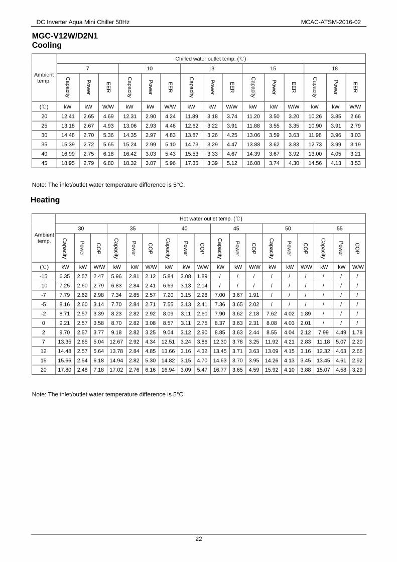
DC Inverter Aqua Mini Chiller 50Hz MCAC-ATSM-2016-02
22
MGC-V12W/D2N1 Cooling
Ambient temp.
Chilled water outlet temp. (℃)
7 10 13 15 18
Capacity
Pow
er
EE
R
Capacity
Pow
er
EE
R
Capacity
Pow
er
EE
R
Capacity
Pow
er
EE
R
Capacity
Pow
er
EE
R
(℃) kW kW W/W kW kW W/W kW kW W/W kW kW W/W kW kW W/W
20 12.41 2.65 4.69 12.31 2.90 4.24 11.89 3.18 3.74 11.20 3.50 3.20 10.26 3.85 2.66
25 13.18 2.67 4.93 13.06 2.93 4.46 12.62 3.22 3.91 11.88 3.55 3.35 10.90 3.91 2.79
30 14.48 2.70 5.36 14.35 2.97 4.83 13.87 3.26 4.25 13.06 3.59 3.63 11.98 3.96 3.03
35 15.39 2.72 5.65 15.24 2.99 5.10 14.73 3.29 4.47 13.88 3.62 3.83 12.73 3.99 3.19
40 16.99 2.75 6.18 16.42 3.03 5.43 15.53 3.33 4.67 14.39 3.67 3.92 13.00 4.05 3.21
45 18.95 2.79 6.80 18.32 3.07 5.96 17.35 3.39 5.12 16.08 3.74 4.30 14.56 4.13 3.53
Note: The inlet/outlet water temperature difference is 5°C.
Heating
Ambient temp.
Hot water outlet temp. (℃)
30 35 40 45 50 55
Capacity
Pow
er
CO
P
Capacity
Pow
er
CO
P
Capacity
Pow
er
CO
P
Capacity
Pow
er
CO
P
Capacity
Pow
er
CO
P
Capacity
Pow
er
CO
P
(℃) kW kW W/W kW kW W/W kW kW W/W kW kW W/W kW kW W/W kW kW W/W
-15 6.35 2.57 2.47 5.96 2.81 2.12 5.84 3.08 1.89 / / / / / / / / /
-10 7.25 2.60 2.79 6.83 2.84 2.41 6.69 3.13 2.14 / / / / / / / / /
-7 7.79 2.62 2.98 7.34 2.85 2.57 7.20 3.15 2.28 7.00 3.67 1.91 / / / / / /
-5 8.16 2.60 3.14 7.70 2.84 2.71 7.55 3.13 2.41 7.36 3.65 2.02 / / / / / /
-2 8.71 2.57 3.39 8.23 2.82 2.92 8.09 3.11 2.60 7.90 3.62 2.18 7.62 4.02 1.89 / / /
0 9.21 2.57 3.58 8.70 2.82 3.08 8.57 3.11 2.75 8.37 3.63 2.31 8.08 4.03 2.01 / / /
2 9.70 2.57 3.77 9.18 2.82 3.25 9.04 3.12 2.90 8.85 3.63 2.44 8.55 4.04 2.12 7.99 4.49 1.78
7 13.35 2.65 5.04 12.67 2.92 4.34 12.51 3.24 3.86 12.30 3.78 3.25 11.92 4.21 2.83 11.18 5.07 2.20
12 14.48 2.57 5.64 13.78 2.84 4.85 13.66 3.16 4.32 13.45 3.71 3.63 13.09 4.15 3.16 12.32 4.63 2.66
15 15.66 2.54 6.18 14.94 2.82 5.30 14.82 3.15 4.70 14.63 3.70 3.95 14.26 4.13 3.45 13.45 4.61 2.92
20 17.80 2.48 7.18 17.02 2.76 6.16 16.94 3.09 5.47 16.77 3.65 4.59 15.92 4.10 3.88 15.07 4.58 3.29
Note: The inlet/outlet water temperature difference is 5°C.

MCAC-ATSM-2016-02 DC Inverter Aqua Mini Chiller 50Hz
23
MGC-V12W/D2RN1
Cooling
Ambient temp.
Chilled water outlet temp. (℃)
7 10 13 15 18
Capacity
Pow
er
EE
R
Capacity
Pow
er
EE
R
Capacity
Pow
er
EE
R
Capacity
Pow
er
EE
R
Capacity
Pow
er
EE
R
(℃) kW kW W/W kW kW W/W kW kW W/W kW kW W/W kW kW W/W
20 12.41 2.56 4.86 12.31 2.80 4.39 11.89 3.07 3.88 11.20 3.38 3.31 10.26 3.72 2.76
25 13.18 2.58 5.10 13.06 2.83 4.61 12.62 3.11 4.05 11.88 3.43 3.47 10.90 3.77 2.89
30 14.48 2.61 5.55 14.35 2.87 5.00 13.87 3.15 4.40 13.06 3.47 3.76 11.98 3.82 3.14
35 15.39 2.63 5.85 15.24 2.89 5.28 14.73 3.18 4.63 13.88 3.50 3.97 12.73 3.86 3.30
40 16.99 2.66 6.40 16.42 2.92 5.62 15.53 3.22 4.83 14.39 3.54 4.06 13.00 3.91 3.32
45 18.95 2.69 7.04 18.32 2.97 6.17 17.35 3.27 5.31 16.08 3.61 4.46 14.56 3.98 3.65
Note: The inlet/outlet water temperature difference is 5°C.
Heating
Ambient temp.
Hot water outlet temp. (℃)
30 35 40 45 50 55
Capacity
Pow
er
CO
P
Capacity
Pow
er
CO
P
Capacity
Pow
er
CO
P
Capacity
Pow
er
CO
P
Capacity
Pow
er
CO
P
Capacity
Pow
er
CO
P
(℃) kW kW W/W kW kW W/W kW kW W/W kW kW W/W kW kW W/W kW kW W/W
-15 6.35 2.53 2.51 5.96 2.76 2.16 5.84 3.03 1.92 / / / / / / / / /
-10 7.25 2.56 2.83 6.83 2.79 2.44 6.69 3.08 2.17 / / / / / / / / /
-7 7.79 2.57 3.02 7.34 2.81 2.61 7.20 3.10 2.32 7.00 3.61 1.94 / / / / / /
-5 8.16 2.56 3.19 7.70 2.80 2.75 7.55 3.08 2.45 7.36 3.59 2.05 / / / / / /
-2 8.71 2.53 3.45 8.23 2.78 2.96 8.09 3.06 2.65 7.90 3.56 2.22 7.62 3.96 1.93 / / /
0 9.21 2.53 3.64 8.70 2.78 3.13 8.57 3.06 2.80 8.37 3.57 2.35 8.08 3.97 2.04 / / /
2 9.70 2.53 3.83 9.18 2.78 3.31 9.04 3.07 2.95 8.85 3.57 2.48 8.55 3.98 2.15 7.99 4.42 1.81
7 13.35 2.61 5.12 12.67 2.88 4.40 12.51 3.19 3.92 12.30 3.72 3.31 11.92 4.15 2.87 11.18 4.99 2.24
12 14.48 2.53 5.73 13.78 2.80 4.93 13.66 3.11 4.39 13.45 3.65 3.68 13.09 4.08 3.21 12.32 4.55 2.71
15 15.66 2.49 6.28 14.94 2.78 5.38 14.82 3.10 4.78 14.63 3.64 4.02 14.26 4.07 3.50 13.45 4.54 2.96
20 17.80 2.44 7.30 17.02 2.72 6.26 16.94 3.05 5.56 16.77 3.60 4.66 15.92 4.03 3.95 15.07 4.51 3.34
Note: The inlet/outlet water temperature difference is 5°C.
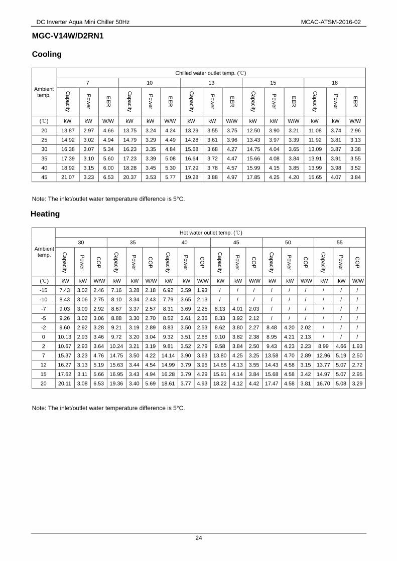
DC Inverter Aqua Mini Chiller 50Hz MCAC-ATSM-2016-02
24
MGC-V14W/D2RN1 Cooling
Ambient temp.
Chilled water outlet temp. (℃)
7 10 13 15 18
Capacity
Pow
er
EE
R
Capacity
Pow
er
EE
R
Capacity
Pow
er
EE
R
Capacity
Pow
er
EE
R
Capacity
Pow
er
EE
R
(℃) kW kW W/W kW kW W/W kW kW W/W kW kW W/W kW kW W/W
20 13.87 2.97 4.66 13.75 3.24 4.24 13.29 3.55 3.75 12.50 3.90 3.21 11.08 3.74 2.96
25 14.92 3.02 4.94 14.79 3.29 4.49 14.28 3.61 3.96 13.43 3.97 3.39 11.92 3.81 3.13
30 16.38 3.07 5.34 16.23 3.35 4.84 15.68 3.68 4.27 14.75 4.04 3.65 13.09 3.87 3.38
35 17.39 3.10 5.60 17.23 3.39 5.08 16.64 3.72 4.47 15.66 4.08 3.84 13.91 3.91 3.55
40 18.92 3.15 6.00 18.28 3.45 5.30 17.29 3.78 4.57 15.99 4.15 3.85 13.99 3.98 3.52
45 21.07 3.23 6.53 20.37 3.53 5.77 19.28 3.88 4.97 17.85 4.25 4.20 15.65 4.07 3.84
Note: The inlet/outlet water temperature difference is 5°C.
Heating
Ambient temp.
Hot water outlet temp. (℃)
30 35 40 45 50 55
Capacity
Pow
er
CO
P
Capacity
Pow
er
CO
P
Capacity
Pow
er
CO
P
Capacity
Pow
er
CO
P
Capacity
Pow
er
CO
P
Capacity
Pow
er
CO
P
(℃) kW kW W/W kW kW W/W kW kW W/W kW kW W/W kW kW W/W kW kW W/W
-15 7.43 3.02 2.46 7.16 3.28 2.18 6.92 3.59 1.93 / / / / / / / / /
-10 8.43 3.06 2.75 8.10 3.34 2.43 7.79 3.65 2.13 / / / / / / / / /
-7 9.03 3.09 2.92 8.67 3.37 2.57 8.31 3.69 2.25 8.13 4.01 2.03 / / / / / /
-5 9.26 3.02 3.06 8.88 3.30 2.70 8.52 3.61 2.36 8.33 3.92 2.12 / / / / / /
-2 9.60 2.92 3.28 9.21 3.19 2.89 8.83 3.50 2.53 8.62 3.80 2.27 8.48 4.20 2.02 / / /
0 10.13 2.93 3.46 9.72 3.20 3.04 9.32 3.51 2.66 9.10 3.82 2.38 8.95 4.21 2.13 / / /
2 10.67 2.93 3.64 10.24 3.21 3.19 9.81 3.52 2.79 9.58 3.84 2.50 9.43 4.23 2.23 8.99 4.66 1.93
7 15.37 3.23 4.76 14.75 3.50 4.22 14.14 3.90 3.63 13.80 4.25 3.25 13.58 4.70 2.89 12.96 5.19 2.50
12 16.27 3.13 5.19 15.63 3.44 4.54 14.99 3.79 3.95 14.65 4.13 3.55 14.43 4.58 3.15 13.77 5.07 2.72
15 17.62 3.11 5.66 16.95 3.43 4.94 16.28 3.79 4.29 15.91 4.14 3.84 15.68 4.58 3.42 14.97 5.07 2.95
20 20.11 3.08 6.53 19.36 3.40 5.69 18.61 3.77 4.93 18.22 4.12 4.42 17.47 4.58 3.81 16.70 5.08 3.29
Note: The inlet/outlet water temperature difference is 5°C.

MCAC-ATSM-2016-02 DC Inverter Aqua Mini Chiller 50Hz
25
MGC-V16W/D2RN1 Cooling
Ambient temp.
Chilled water outlet temp. (℃)
7 10 13 15 18
Capacity
Pow
er
EE
R
Capacity
Pow
er
EE
R
Capacity
Pow
er
EE
R
Capacity
Pow
er
EE
R
Capacity
Pow
er
EE
R
(℃) kW kW W/W kW kW W/W kW kW W/W kW kW W/W kW kW W/W
20 16.07 3.46 4.64 15.98 3.78 4.23 15.44 4.13 3.74 14.50 4.53 3.20 12.81 4.32 2.96
25 17.32 3.53 4.91 17.19 3.86 4.45 16.59 4.22 3.93 15.57 4.61 3.38 13.76 4.40 3.13
30 19.03 3.61 5.27 18.87 3.94 4.80 18.21 4.30 4.23 17.09 4.71 3.63 15.10 4.48 3.37
35 20.21 3.66 5.52 20.02 3.99 5.02 19.33 4.36 4.43 18.14 4.77 3.81 16.04 4.54 3.53
40 21.99 3.74 5.89 21.25 4.07 5.22 20.08 4.45 4.52 18.52 4.86 3.81 16.13 4.62 3.49
45 24.51 3.84 6.38 23.68 4.19 5.65 22.37 4.57 4.90 20.65 4.98 4.15 18.02 4.74 3.80
Note: The inlet/outlet water temperature difference is 5°C.
Heating
Ambient temp.
Hot water outlet temp. (℃)
30 35 40 45 50 55
Capacity
Pow
er
CO
P
Capacity
Pow
er
CO
P
Capacity
Pow
er
CO
P
Capacity
Pow
er
CO
P
Capacity
Pow
er
CO
P
Capacity
Pow
er
CO
P
(℃) kW kW W/W kW kW W/W kW kW W/W kW kW W/W kW kW W/W kW kW W/W
-15 8.29 3.43 2.42 8.08 3.73 2.17 7.89 4.08 1.94 / / / / / / / / /
-10 9.38 3.49 2.69 9.11 3.79 2.40 8.84 4.15 2.13 / / / / / / / / /
-7 10.04 3.52 2.85 9.72 3.83 2.54 9.41 4.20 2.24 9.24 4.56 2.03 / / / / / /
-5 10.26 3.42 3.00 9.92 3.73 2.66 9.60 4.09 2.35 9.41 4.44 2.12 / / / / / /
-2 10.58 3.27 3.23 10.22 3.57 2.86 9.87 3.91 2.52 9.66 4.25 2.27 9.31 4.69 1.99 / / /
0 11.18 3.28 3.40 10.79 3.56 3.03 10.41 3.93 2.65 10.18 4.27 2.38 9.80 4.71 2.08 / / /
2 11.77 3.30 3.57 11.36 3.54 3.21 10.95 3.94 2.78 10.71 4.29 2.49 10.29 4.73 2.18 9.89 5.22 1.89
7 17.61 3.71 4.75 17.00 4.00 4.25 16.38 4.46 3.67 16.00 4.85 3.30 15.37 5.35 2.87 14.75 5.90 2.50
12 18.37 3.60 5.10 17.73 3.95 4.48 17.08 4.35 3.93 16.69 4.74 3.52 16.03 5.22 3.07 15.37 5.77 2.67
15 19.92 3.60 5.53 19.23 3.95 4.86 18.54 4.35 4.27 18.11 4.75 3.82 17.40 5.24 3.32 16.69 5.79 2.88
20 22.76 3.59 6.33 21.99 3.94 5.58 21.23 4.35 4.88 20.75 4.75 4.37 19.94 5.25 3.80 19.13 5.80 3.30
Note: The inlet/outlet water temperature difference is 5°C.

DC Inverter Aqua Mini Chiller 50Hz MCAC-ATSM-2016-02
26
11. Operation Limits
11.1 Ethylene Glycol Solutions
Water and ethylene glycol solutions used as a thermal vector in the place of water reduce the performance
of the unit. Multiply the performance figures by the values given in the following table.
Freezing point (°C)
0 -5 -10 -15 -20 -25
Percentage of ethylene glycol in weight
0 12% 20% 28% 35% 40%
cPf 1 0.98 0.97 0.965 0.96 0.955
cQ 1 1.02 1.04 1.075 1.11 1.14
cdp 1 1.07 1.11 1.18 1.22 1.24
cPf: Correction factor of heating/cooling capacity cQ: Correction factor of flow rate cdp: Correction factor of pressure
drop
COOLING
DELIVERY WATER TEMPERATURE
ER
UT
AR
EP
ME
TRI
AE
DIST
UO
C
-
-10 4 5 7 15 20
-5
20
35
46
C
HEATING
DELIVERY WATER TEMPERATURE
ER
UT
AR
EP
ME
TRI
AE
DIST
UO
30 45 55
-15
-3
7
27
35
20
C
C

MCAC-ATSM-2016-02 DC Inverter Aqua Mini Chiller 50Hz
27
Note:
1. During winter leaving the unit unused, please drain water out completely from unit if no anti-freeze were charged into
pipeline, or keep power on (at standby or off status) and ensure that water is contained inside of unit.
2. When ambient temperature low than 5℃, running cooling mode must be charged antifreeze. Refer to the upper table for the
charged volume.
11.2 Fouling Factors
The performance data given refer to conditions with clean evaporator plates (fouling factor=1). For different
fouling factors, multiply the figures in the performance tables by the coefficient given in the following table.
Fouling factors Evaporator
(m 2 °C/W) f1 fk1 fx1
4.4×10⁻⁵
- - -
0.86×10⁻⁴
0.96 0.99 0.99
1.72×10⁻⁴
0.93 0.98 0.98
f1: Correction factor of capacity
fk1: Power input correction factor of compressor
fx1: Correction factor of total power input

DC Inverter Aqua Mini Chiller 50Hz MCAC-ATSM-2016-02
28
12. Hydraulic Data
12.1 Useful pump head curves
P-C (constant) curve for 5/7 kW
P-C(constant) curve for 10/12/14/16 kW

MCAC-ATSM-2016-02 DC Inverter Aqua Mini Chiller 50Hz
29
12.2 Water Side Water Pressure Drop
MGC-V5W/D2N1, MGC-V7W/D2N1
MGC-V10W/D2N1
Heat exchanger pressure drop (water side) 研发提供

DC Inverter Aqua Mini Chiller 50Hz MCAC-ATSM-2016-02
30
MGC-V12W/D2N1, MGC-V12W/D2RN1
MGC-V14W/D2RN1

MCAC-ATSM-2016-02 DC Inverter Aqua Mini Chiller 50Hz
31
MGC-V16W/D2RN1
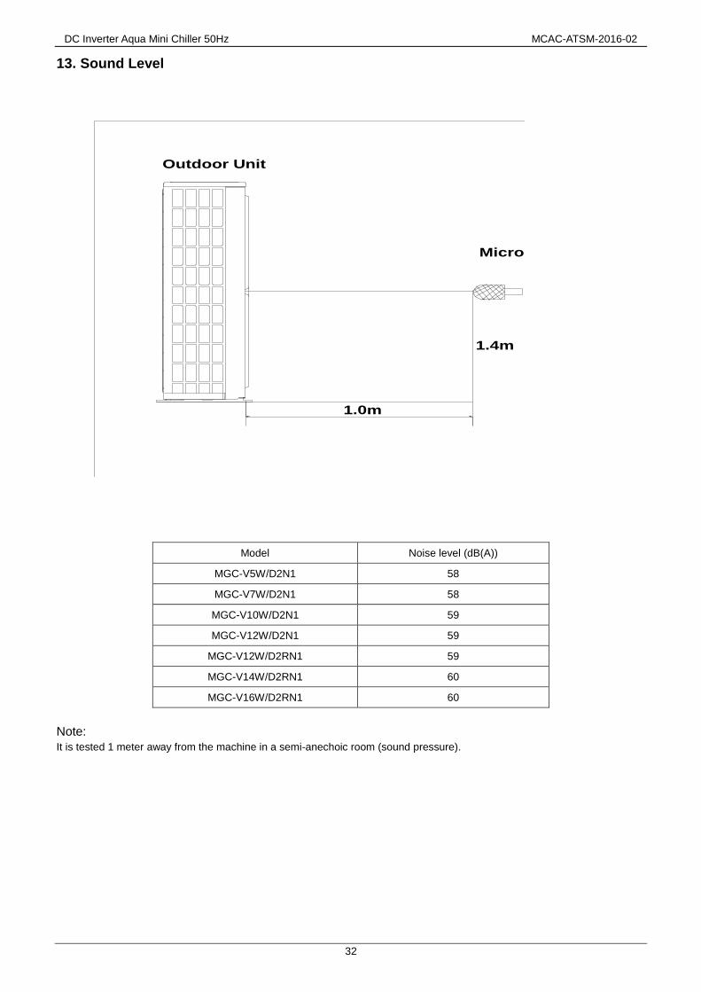
DC Inverter Aqua Mini Chiller 50Hz MCAC-ATSM-2016-02
32
13. Sound Level
Model Noise level (dB(A))
MGC-V5W/D2N1 58
MGC-V7W/D2N1 58
MGC-V10W/D2N1 59
MGC-V12W/D2N1 59
MGC-V12W/D2RN1 59
MGC-V14W/D2RN1 60
MGC-V16W/D2RN1 60
Note:
It is tested 1 meter away from the machine in a semi-anechoic room (sound pressure).
1.0m
Microphone
Outdoor Unit
1.4m

MCAC-ATSM-2016-02 DC Inverter Aqua Mini Chiller 50Hz
33
14. Exploded View
MGC-V5W/D2N1, MGC-V7W/D2N1
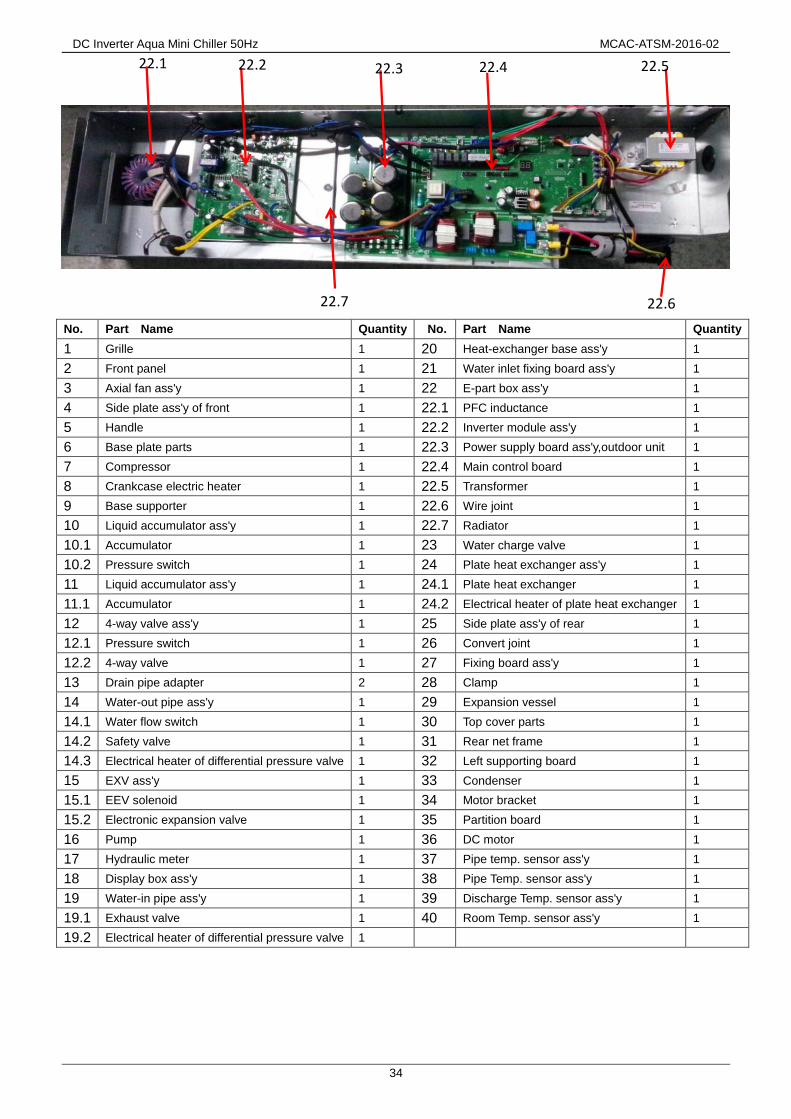
DC Inverter Aqua Mini Chiller 50Hz MCAC-ATSM-2016-02
34
No. Part Name Quantity No. Part Name Quantity
1 Grille 1 20 Heat-exchanger base ass'y 1
2 Front panel 1 21 Water inlet fixing board ass'y 1
3 Axial fan ass'y 1 22 E-part box ass'y 1
4 Side plate ass'y of front 1 22.1 PFC inductance 1
5 Handle 1 22.2 Inverter module ass'y 1
6 Base plate parts 1 22.3 Power supply board ass'y,outdoor unit 1
7 Compressor 1 22.4 Main control board 1
8 Crankcase electric heater 1 22.5 Transformer 1
9 Base supporter 1 22.6 Wire joint 1
10 Liquid accumulator ass'y 1 22.7 Radiator 1
10.1 Accumulator 1 23 Water charge valve 1
10.2 Pressure switch 1 24 Plate heat exchanger ass'y 1
11 Liquid accumulator ass'y 1 24.1 Plate heat exchanger 1
11.1 Accumulator 1 24.2 Electrical heater of plate heat exchanger 1
12 4-way valve ass'y 1 25 Side plate ass'y of rear 1
12.1 Pressure switch 1 26 Convert joint 1
12.2 4-way valve 1 27 Fixing board ass'y 1
13 Drain pipe adapter 2 28 Clamp 1
14 Water-out pipe ass'y 1 29 Expansion vessel 1
14.1 Water flow switch 1 30 Top cover parts 1
14.2 Safety valve 1 31 Rear net frame 1
14.3 Electrical heater of differential pressure valve 1 32 Left supporting board 1
15 EXV ass'y 1 33 Condenser 1
15.1 EEV solenoid 1 34 Motor bracket 1
15.2 Electronic expansion valve 1 35 Partition board 1
16 Pump 1 36 DC motor 1
17 Hydraulic meter 1 37 Pipe temp. sensor ass'y 1
18 Display box ass'y 1 38 Pipe Temp. sensor ass'y 1
19 Water-in pipe ass'y 1 39 Discharge Temp. sensor ass'y 1
19.1 Exhaust valve 1 40 Room Temp. sensor ass'y 1
19.2 Electrical heater of differential pressure valve 1
22.1 22.2 22.3 22.4 22.5
22.6 22.7

MCAC-ATSM-2016-02 DC Inverter Aqua Mini Chiller 50Hz
35
MGC-V10W/D2N1, MGC-V12W/D2N1

DC Inverter Aqua Mini Chiller 50Hz MCAC-ATSM-2016-02
36
No. Part Name Quantity No. Part Name Quantity
1 Right-front plate ass'y 1 21 Gas-liquid separator 1
2 Four-way valve parts 1 22 Differential pressure switch 1
2.1 Four-way valve ass'y 1 23 Hydraulic meter 1
2.2 Pressure switch 1 24 Display box ass'y 1
3 Welded parts of base 1 25 Outdoor electrical control box ass'y 1
4 Suction pipe ass'y 1 25.1 Module board ass'y 1
4.1 Pressure controller 1 25.2 Radiator 1
5 Accumulator ass'y 1 25.3 Terminal block, 3P 2
6 Fixed plate ass'y of compressor 1 25.4 Radiator 1
7 Compressor 1 25.5 Three phase bridge 1
8 EXV ass'y 1 25.6 Transformer 1
8.1 Electronic expansion valve 1 25.7 Electrolytic capacitor 2
8.2 Expansion valve wire(CAM-MD12GRSZ-5) 1 25.8 Wire joints,12P 1
9 Exhaust valve ass'y 1 25.9 Outdoor control board ass'y 1
9.1 Exhaust valve 1 26 Right back plate 1
10 Connection pipe ass'y 1 27 Inductance Box Ass'y 1
11 Base 1 27.1 PFC Inductor 2
12 Fixed plate of inlet/outlet pipe 1 28 Condenser ass'y 1
13 Connection pipe parts of water pump 1 29 Coaming ass'y 1
13.1 Water charge valve 1 30 Bracket ass'y, net 1
13.2 Safety valve 1 31 Installation plate of expansion tank 1
14 Drain pipe adapter 2 32 Top cover ass'y 1
15 Water pump 1 33 Expansion vessel 1
16 Coaming I 1 34 Rear-left supporting board 1
17 Plate heat exchanger ass'y 1 35 Motor bracket assembly 1
17.1 Electrical heater of plate heat exchanger 1 36 DC Motor 2
17.2 Plate heat exchanger 1 37 Axial fan 2
18 Rubber gasket 1 38 Front Panel 1
19 Coaming II 1 39 Net 2
20 Connection pipe ass'y of differential pressure valve 1 40 Handle 3
20.1 Electrical heater of differential pressure valve 1
25.1
25.2
25.3
25.6
25.7
25.4 25.5
25.9
25.8

MCAC-ATSM-2016-02 DC Inverter Aqua Mini Chiller 50Hz
37
MGC-V12W/D2RN1, MGC-V14W/D2RN1, MGC-V16W/D2RN1

DC Inverter Aqua Mini Chiller 50Hz MCAC-ATSM-2016-02
38
No. Part Name Quantity No. Part Name Quantity
1 Right-front plate ass'y 1 22 Differential pressure switch 1
2 Four-way valve parts 1 23 Hydraulic meter 1
2.1 Four-way valve ass'y 1 24 Display box ass'y 1
2.2 Pressure switch 1 25 Outdoor electrical control box ass'y 1
3 Welded parts of base 1 25.1 Inverter module 1
4 Suction pipe ass'y 1 25.2 Radiator 1
4.1 Pressure controller 1 25.3 Three phase bridge 1
5 Accumulator ass'y 1 25.4 Aluminum electrolytic capacitors 2
6 Fixed plate ass'y of compressor 1 25.5 outdoor unit power supply board 1
7 Compressor 1 25.6 Resistance 2
8 EXV ass'y 1 25.7 AC contactor 1
8.1 Electronic expansion valve 1 25.8 Wire joints,14P 1
8.2 Expansion valve wire(CAM-MD12GRSZ-5) 1 25.9 Outdoor main control board ass'y 1
9 Exhaust valve ass'y 1 25.10 Wire joint, 2p 1
9.1 Exhaust valve 1 25.11 Terminal block, 3P 1
10 Connection pipe ass'y 1 26 Right back plate 1
11 Base 1 27 Inductance parts ass'y 1
12 Fixed plate of inlet/outlet pipe 1 27.1 Reactance 1
13 Connection pipe parts of water pump 1 28 Condenser ass'y 1
13.1 Water charge valve 1 29 Coaming ass'y 1
13.2 Safety valve 1 30 Bracket ass'y, net 1
14 Drain pipe adapter 2 31 Installation plate of expansion tank 1
15 Water pump 1 32 Top cover ass'y 1
16 Coaming I 1 33 Expansion vessel 1
17 Plate heat exchanger ass'y 1 34 Rear-left supporting board 1
17.1 Plate heat exchanger 1 35 Motor bracket assembly 1
17.2 Electrical heater of plate heat exchanger 1 36 DC Motor 2
18 Rubber gasket 1 37 Axial fan 2
19 Coaming II 1 38 Front Panel 1
20 Connection pipe ass'y of differential pressure valve 1 39 Net 2
20.1 Electrical heater of differential pressure valve 1 40 Handle 3
21 Gas-liquid separator 1
25.1
25.2
25.3
25.4
25.5
25.6
25.7
25.9
25.825.10
25.11

MCAC-ATSM-2016-02 DC Inverter Aqua Mini Chiller 50Hz
39
15. Installation
15.1 Installation of general information
General warning
1. These units have been designed to chilled and hot water and must be used in applications compatible
with their performance characteristics; these appliances are designed for residential or similar applications.
2. Incorrect installation, regulation and maintenance or improper use absolves the manufacturer from all
liability, whether contractual or otherwise, for damage to people, animals or things. Only those applications
specifically indicated in this list are permitted.
3. Read this manual carefully. All work must be carried out by qualified personnel in conformity with
legislation in force in the country concerned.
4. The guarantee is invalidated if the above instructions are not respected and if the unit is started up for the
first time without the presence of personnel authorized by the Company (where specified in the supply
contract) who should draw up a “start-up” report.
5. The documentation supplied with the unit must be consigned to the owner who should keep it carefully for
future consultation in the event of maintenance or service.
6. All repair or maintenance work must be carried out by the Company’s Technical Service or qualified
personnel following the instructions in this manual. The air-conditioner must under no circumstances be
modified or tampered with as this may create situations of risk. Failure to observe this condition absolves the
manufacturer of all liability for resulting damage.
Fundamental safety rules
When operating equipment involving the use of electricity and water, a number of fundamental safety rules
must be observed, namely:
Prohibition
1. This appliance is not intended for use by persons (including children) with reduced physical, sensory or
mental capabilities, or lack of experience and knowledge, unless they have been given supervision or
instruction concerning use of the appliance by a person responsible for their safety.
2. Do not touch the unit with bare feet or with wet or damp parts of the body.
3. Do not carry out cleaning operations without first disconnecting the system from the electricity supply.
4. Do not modify safety or regulation devices without authorization and instructions from the manufacturer.
5. Do not pull, detach or twist the electrical cables coming from the unit, even when disconnected from the
mains electricity supply.
6. Do not open doors or panels providing access to the internal parts of the unit without first ensuring that the
mains switch is in the off position.
7. Do not introduce pointed objects through the air intake and outlet grills.
8. Do not dispose of, abandon or leave within reach of children packaging materials (cardboard, staples,
plastic bags, etc.) as they may represent a hazard.
Important
1. The chiller appliances are supplied without the main switch. The power supply to the unit must be
disconnected using a suitable main switch that must be supplied and installed by the installer.
2. Respect safety distances between the unit and other equipment or structures. Guarantee adequate space
for access to the unit for maintenance and/or service operations.
Power supply: the cross section of the electrical cables must be adequate for the power of the unit and the
power supply voltage must correspond with the value indicated on the respective units. All units must be
earthed in conformity with legislation in force in the country concerned.

DC Inverter Aqua Mini Chiller 50Hz MCAC-ATSM-2016-02
40
3. Hydraulic connections should be carried out as indicated in the instructions to guarantee correct operation
of the unit. Empty the water circuit or add glycol if the unit is not used during the winter. Handle the unit with
the utmost care to avoid damage.
15.2 Installation of outdoor unit
Choice of installation site
Before installing the unit, agree with the customer the site where it will be installed, taking the following
points into consideration:
- Check that the fixing points are adequate to support the weight of the unit.
- Pay scrupulous respect to safety distances between the unit and other equipment or structures to ensure
that air entering the unit and discharged by the fans is free to circulate.
Positioning
Before handling the unit, check the capacity of the lifting equipment used, respecting the instructions on the
packaging.
To move the unit in the horizontal, make appropriate use of a lift truck or similar, bearing in mind the weight
distribution of the unit. To lift the unit, insert tubes long enough to allow positioning of the lifting slings and
safety pins in the feet on the unit.
To avoid the slings damaging the unit, place protection between the slings and the unit. Position the unit in
the site indicated by the customer. Place either a layer of rubber (min. thickness 10 mm) or vibration damper
feet (optional) between the base and support surface. Fix the unit, making sure it is level and that there is
easy access to hydraulic and electrical components. If the site of installation is exposed to strong winds, fix
the unit adequately to the support surface using tie rods if necessary. If a heat pump unit is being installed,
make sure the condensate is drained using the drain hose supplied as standard. Prevent leaves, branches
or snow from accumulating around the unit. These could reduce the efficiency of the unit.
Installation space (units: mm)
1. Since the gravity center of the unit is not at its physical center, so please be careful when lifting it with a
sling.
2. Never hold the inlet of the outdoor unit to prevent it from deforming.
3. Do not touch the fan with hands or other objects.
4. Do not lean it more than 45℃, and do not lay it sidelong.
5. Make concrete foundation according to the specifications of the outdoor units.
6. Fasten the feet of this unit with bolts firmly to prevent it from collapsing in case of earthquake or strong
wind.
>6
0c
m
Fix with bolt

MCAC-ATSM-2016-02 DC Inverter Aqua Mini Chiller 50Hz
41
Single unit installation
Parallel connect two units or above
Parallel connect the front with rear sides
All the pictures in this manual are for explanation purpose only. They may be slightly different from the air conditioner you purchased (depend on model). The actual shape shall prevail. 15.3 Hydraulic connection
The choice and installation of components is the responsibility of the installer who should follow good
working practice and current legislation. Before connecting the pipes, make sure they do not contain stones,
sand, rust, or others which might damage the unit. Construction of a bypass is recommended to enable the
pipes to be washed through without having to disconnect the unit (see drain valves). The connection piping
should be supported in such a way as to avoid it weighing on the unit. It is recommended that the following
devices are installed in the water circuit of the evaporator. A hydraulic safety valve shall be mounted in water
system, which should open constantly.
>300
>600
>30
0
>20
00
(Wall or obstacle)
Maintainchannel
Air outlet
Air inlet
Air inlet
>600
>2000
>300
>2000 >500 >3000 >3000 >300

DC Inverter Aqua Mini Chiller 50Hz MCAC-ATSM-2016-02
42
Connecting drawing of pipeline system
MGC-V5W/D2N1 & MGC-V7W/D2N1
MGC-V10W/D2N1, MGC-V12W/D2N1, MGC-V12W/D2RN1, MGC-V14W/D2RN1&MGC-V16W/D2RN1
1
Factory Connections Installer Connections
A
WATER INLET
WATER OUTLET
3
4
7
2
5
6
8
9
10
10
11
12
13
11
6
9
9
1 Plate Heat Exchange2 Differential Pressure Switch3 Automatic Discharge Valve4 Expansion Tank
5 Auto-watet replenishing6 Circulating Pump7 Pressure Gauge8 Safety Valve
9 Drain/Chemical Washing Valve
10 Flexible Joint11 Thermometer12 Calibrating Valve13 Filter
7
7
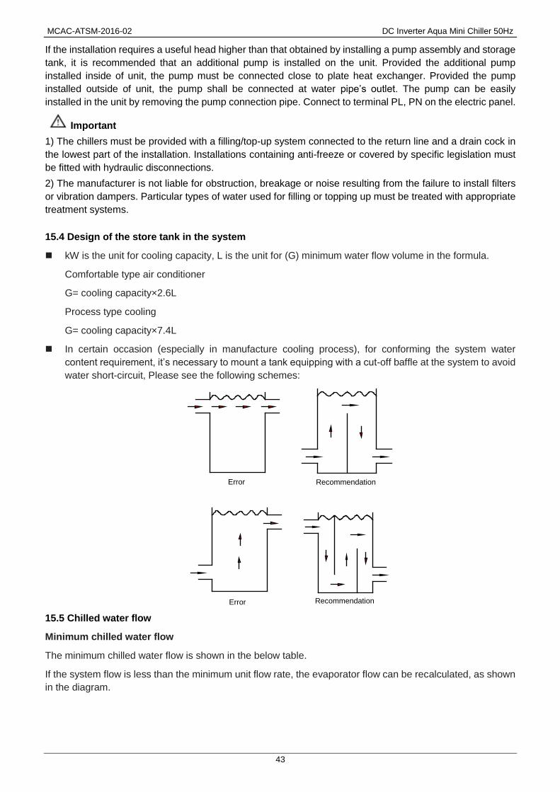
MCAC-ATSM-2016-02 DC Inverter Aqua Mini Chiller 50Hz
43
If the installation requires a useful head higher than that obtained by installing a pump assembly and storage
tank, it is recommended that an additional pump is installed on the unit. Provided the additional pump
installed inside of unit, the pump must be connected close to plate heat exchanger. Provided the pump
installed outside of unit, the pump shall be connected at water pipe’s outlet. The pump can be easily
installed in the unit by removing the pump connection pipe. Connect to terminal PL, PN on the electric panel.
Important
1) The chillers must be provided with a filling/top-up system connected to the return line and a drain cock in
the lowest part of the installation. Installations containing anti-freeze or covered by specific legislation must
be fitted with hydraulic disconnections.
2) The manufacturer is not liable for obstruction, breakage or noise resulting from the failure to install filters
or vibration dampers. Particular types of water used for filling or topping up must be treated with appropriate
treatment systems.
15.4 Design of the store tank in the system
kW is the unit for cooling capacity, L is the unit for (G) minimum water flow volume in the formula.
Comfortable type air conditioner
G= cooling capacity×2.6L
Process type cooling
G= cooling capacity×7.4L
In certain occasion (especially in manufacture cooling process), for conforming the system water
content requirement, it’s necessary to mount a tank equipping with a cut-off baffle at the system to avoid
water short-circuit, Please see the following schemes:
15.5 Chilled water flow
Minimum chilled water flow
The minimum chilled water flow is shown in the below table.
If the system flow is less than the minimum unit flow rate, the evaporator flow can be recalculated, as shown
in the diagram.
Error Recommendation
Fig.4-4
Error Recommendation
Error Recommendation
Fig.4-4
Error Recommendation

DC Inverter Aqua Mini Chiller 50Hz MCAC-ATSM-2016-02
44
Maximum chilled water flow
The maximum chilled water flow is limited by the permitted pressure drop in the evaporator. It is provided in
the below table. If the system flow is more than the maximum unit flow rate, bypass the evaporator as shown
in the diagram to obtain a lower evaporator flow rate.
Minimum and maximum water flow rates
Item Water flow rate(m3/h)
Model Minimum Maximum
MGC-V5W/D2N1 0.77 0.95
MGC-V7W/D2N1 1.08 1.32
MGC-V10W/D2N1 1.54 1.89
MGC-V12W/D2N1 1.72 2.11
MGC-V12W/D2RN1 1.72 2.11
MGC-V14W/D2RN1 1.93 2.36
MGC-V16W/D2RN1 2.24 2.73
15.6 Design of expansion tank
If a closed expansion tank with its filled volume of air is too small, the system pressure will easily exceed the
maximum allowable pressure and cause water to discharge from the pressure relief valve, thus wasting
water. If the closed tank is too large, when the water temperature drops, the system pressure may decrease
to a level below the minimum allowable value and cause trouble in the air vent. Therefore, accurate sizing of
a closed expansion tank is essential.
For diaphragm expansion tanks, the minimum volume of the water tank, Vt, gal (m3), can be calculated by
the following formula, recommended by ASHRAE Handbook 1996, HVAC Systems and Equipment:
Vt=Vs v2/v1-1-3α(T2-T1)
1-p1/p2
T1=lower temperature, ℉ (℃)
T2=higher temperature, ℉ (℃)
Vs=volume of water in system, gal(m3)
p1=absolute pressure at lower temperature, psia (kPa abs.)
p2=absolute pressure at higher temperature, psia (kPa abs.)
v1, v2 =specific volume of water at lower and higher temperature, respectively, ft3/lb(m3/kg)
α=linear coefficient of thermal expansion; for steel, α=6.5x10⁻⁶in./in·℉(1.2x10-5per℃); For copper,
α=9.5x10⁻⁶in./in·℉(1.7x10-5per℃)
Evaporator
Recirculation
For minimum chilled water flow rate
Fig. 4-2
For maximum chilled water flow rate
Evaporator
Recirculation

MCAC-ATSM-2016-02 DC Inverter Aqua Mini Chiller 50Hz
45
In a chilled water system, the higher temperature T2 is the highest anticipated ambient temperature when
the chilled water system shuts down during summer. The lower temperature in a heating system is often the
ambient temperature at fill conditions(for example, 50℉ or 10℃).
15.7 Water quality control
When industrial water is used as chilled water, little furring may occur; however, well water or river water,
used as chilled water, may cause much sediment, such as furring, sand, and so on. Therefore, well water or
river water must be filtered and softened in softening water equipment before flowing into chilled water
system. If sand and clay settle in the evaporator, circulation of chilled water may be blocked, and thus
leading to freezing accidents; if hardness of chilled water is too high, furring may occur easily, and the
devices may be corroded. Therefore, the quality of chilled water should be analyzed before being used, such
as PH value, conductivity, concentration of chloride ion, concentration of sulfide ion, and so on.
PH 6~8
Total hardness less than 50 ppm
Electrical conductivity less than 200 mV/cm (25℃)
Sulfide ion none
Chlorine ions less than 50 ppm
Ammonia ions none
Sulfate ion less than 50 ppm
Silicon less than 30 ppm
Total iron less than 0.3 ppm
Sodium ion No requirement
Calcium ion less than 50 ppm
Filling the installation
Before filling, check that the installations drain cock is closed.
Open all installation and terminal air vents.
Open the gate valves.
Begin filling, slowly opening the water filling cock outside the unit.
When water begins to leak out of the terminal air vent valves, close them and continue filling until the
pressure gauge indicates a pressure of 1.5 bars.
Emptying the installation
Before emptying, place the mains switch in the“off”position.
Make sure the installation fill/top-up water cock is closed.
Open the drain cock outside the unit and all the installation and terminal air vent valves.

DC Inverter Aqua Mini Chiller 50Hz MCAC-ATSM-2016-02
46
Size and position of connections
For MGC-V5W/D2N1 & MGC-V7W/D2N1
Model A
(mm)
B
(mm)
C
(mm)
D
(mm)
E
(mm)
F
(mm)
Water
inlet/outlet
(Ø)
Auto-water
replenishing
(Ø)
Security
discharge (Ø)
MGC-V5W/D2N1
MGC-V7W/D2N1 95 126 250 360 68 114 R1 G1/2 G1/2
For MGC-V10W/D2N1, MGC-V12W/D2RN1, MGC-V14W/D2RN1, MGC-V16W/D2RN1
Model A
(mm)
B
(mm)
C
(mm)
D
(mm)
E
(mm)
F
(mm)
Water
inlet/outlet (Ø)
Auto-water
replenishing (Ø)
Security
discharge (Ø)
MGC-V10W/D2N1
MGC-V12W/D2N1
MGC-V12W/D2RN1
MGC-V14W/D2RN1
MGC-V16W/D2RN1
300 195 155 105 68 105 R5/4 G1/2 G1/2
Important
a) The installation must be filled to a pressure of between 1 and 2 bars.
b) It is recommended that this operation be repeated after the unit has been operating for a number of
hours. The pressure of the installation should be checked regularly and if it drops below 1 bar, the water
content should be topped-up.
c) Check the hydraulic tightness of joints.
d) An all-pole disconnection device which has at least 3mm separation distance in all pole and a residual
current device (RCD) with the rating of above 10mA shall be incorporated in the fixed wiring according to the
D
A
E
B
F
C
water inlet
auto-waterreplenishing orifice
security discharge
water outlet
E
F
C D
BA
water outlet
auto-waterreplenishing orifice
security discharge water inlet

MCAC-ATSM-2016-02 DC Inverter Aqua Mini Chiller 50Hz
47
national rule the appliance shall be installed in accordance with national wiring regulations.
e) If the fluid in the circuit contains anti-freeze, it should not be allowed to drain freely as it is pollutant. It
should be collected for possible reuse. When draining after heat pump operation, take care as the water may
be hot (up to 50°).
15.8 Electrical connection
The unitary mini chillers leave the factory already wired, and require the installation of an omni polar thermal
overload switch, a lockable mains disconnecting switch for the connection to the mains power supply, and
the connection of the flow switch to the corresponding terminals. All the above operations must be carried
out by qualified personnel in compliance with the legislation in force.
For all electrical work, refer to the electrical wiring diagrams in this manual. You are also recommended to
check that the characteristics of the mains electricity supply are adequate for the absorptions indicated in the
electrical characteristics table below, also bearing in mind the possible use of other equipment at the same
time.
Important
Power to the unit must be turned on only after installation work (hydraulic and electrical) has been
completed.
All electrical connections must be carried out by qualified personnel in accordance with legislation
in force in the country concerned.
Respect instructions for connecting phase, neutral and earth conductors.
The power line should be fitted upstream with a suitable device to protect against short-circuits and
leakage to earth, isolating the installation from other equipment.
Voltage must be within a tolerance of ±10% of the rated power supply voltage for the unit (for three
phase units, the unbalance between the phases must not exceed 3%).If these parameters are not
respected, contact the electricity supply company.
For electrical connections, use double insulation cable in conformity with current legislation in the
country concerned.
An omnipolar thermal overload switch and a lockable mains disconnecting switch, in compliance
with the CEI-EN standards (contact opening of at least 3mm), with adequate switching and residual
current protection capacity based on the electrical data table shown below, must be installed as
near as possible to the appliance.
The devices on the unit must be lockable. An efficient earth connection is obligatory. Failure to
earth the appliance absolves the manufacturer of all liability for damage.
Do not use water pipes to earth the unit.

DC Inverter Aqua Mini Chiller 50Hz MCAC-ATSM-2016-02
48
Electrical Panel
The electrical panel is located inside the unit at the top of the technical compartment where the various
components of the refrigerant circuit are also to be found.
To access the electrical panel, remove the front panel of the unit by undoing the screws.
5/7kW 10~16kW
Electrical Power Connection MGC-V5W/D2N1, MGC-V7W/D2N1, MGC-V10W/D2N1, MGC-V12W/D2N1
NOTE: The outdoor units must be installed with a Residual Current Circuit-breaker near the power supply and must be
effectively earthed.
NL 31 2 64 5 7 8GND
PUMP2 Remote alarm Remote shutdownRemote cooling/heating wire controller
9 10 11
NL GND
AC 220-240V 50Hz
L N
Residual Current
Circuit-breaker
GND

MCAC-ATSM-2016-02 DC Inverter Aqua Mini Chiller 50Hz
49
MGC-V12W/D2RN1, MGC-V14W/D2RN1, MGC-V16W/D2RN1
Additional pump
“PUMP2” terminal only provides passive switching signal.
Additional water pump must be controlled by the AC contactor.
NC 31 2 64 5 7 8GND 9 10 11BA
PUMP2 Remote alarm Remote shutdown Remote cooling/heating wire controller
AC 380-415V 50Hz
Residual Current
Circuit-breakerGND
NC GNDBA
A B C N
1 2
Additional pump
L
N 220-240V
220-240VL
N A1
A2AC contactor
Main control
board
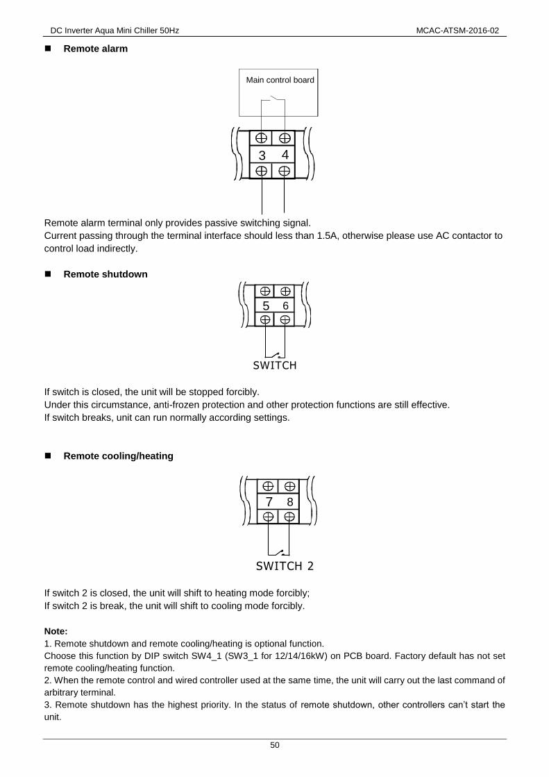
DC Inverter Aqua Mini Chiller 50Hz MCAC-ATSM-2016-02
50
Remote alarm
Remote alarm terminal only provides passive switching signal.
Current passing through the terminal interface should less than 1.5A, otherwise please use AC contactor to
control load indirectly.
Remote shutdown
If switch is closed, the unit will be stopped forcibly.
Under this circumstance, anti-frozen protection and other protection functions are still effective.
If switch breaks, unit can run normally according settings.
Remote cooling/heating
If switch 2 is closed, the unit will shift to heating mode forcibly;
If switch 2 is break, the unit will shift to cooling mode forcibly.
Note:
1. Remote shutdown and remote cooling/heating is optional function.
Choose this function by DIP switch SW4_1 (SW3_1 for 12/14/16kW) on PCB board. Factory default has not set
remote cooling/heating function.
2. When the remote control and wired controller used at the same time, the unit will carry out the last command of
arbitrary terminal.
3. Remote shutdown has the highest priority. In the status of remote shutdown, other controllers can’t start the
unit.
3 4
Main control board
5 6
SWITCH
SWITCH 2
7 8
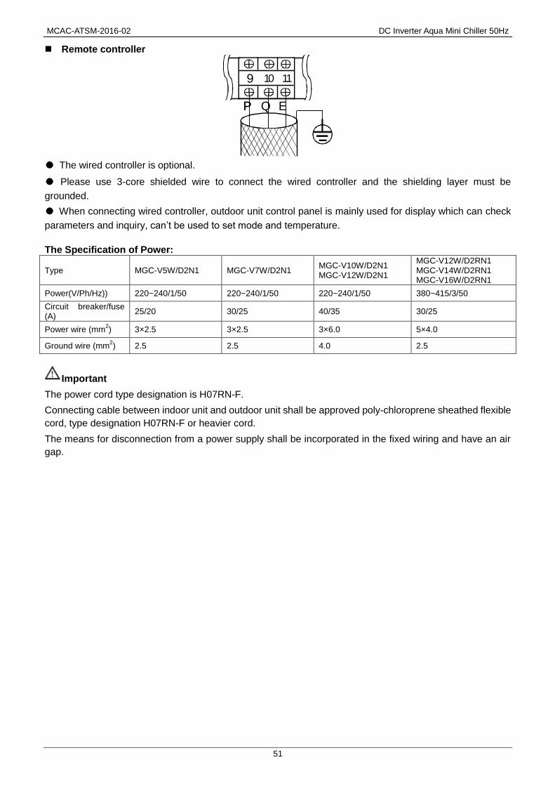
MCAC-ATSM-2016-02 DC Inverter Aqua Mini Chiller 50Hz
51
Remote controller
● The wired controller is optional.
● Please use 3-core shielded wire to connect the wired controller and the shielding layer must be
grounded.
● When connecting wired controller, outdoor unit control panel is mainly used for display which can check
parameters and inquiry, can’t be used to set mode and temperature.
The Specification of Power:
Type MGC-V5W/D2N1 MGC-V7W/D2N1 MGC-V10W/D2N1 MGC-V12W/D2N1
MGC-V12W/D2RN1 MGC-V14W/D2RN1 MGC-V16W/D2RN1
Power(V/Ph/Hz)) 220~240/1/50 220~240/1/50 220~240/1/50 380~415/3/50
Circuit breaker/fuse (A)
25/20 30/25 40/35 30/25
Power wire (mm2) 3×2.5 3×2.5 3×6.0 5×4.0
Ground wire (mm2) 2.5 2.5 4.0 2.5
Important
The power cord type designation is H07RN-F.
Connecting cable between indoor unit and outdoor unit shall be approved poly-chloroprene sheathed flexible
cord, type designation H07RN-F or heavier cord.
The means for disconnection from a power supply shall be incorporated in the fixed wiring and have an air
gap.
9 10 11
PP Q E

DC Inverter Aqua Mini Chiller 50Hz MCAC-ATSM-2016-02
52
16. Checking and Starting Up the Unit
Preparing for first start up
Restart after shutting down for long periods.
The chiller must be started up for the first time by the Technical Service. Before starting up the chillers, make
sure that:
- All safety conditions have been respected.
- The chiller is adequately fixed to the surface it rests on.
- Functional distances have been respected.
- Hydraulic connections have been carried out as indicated in the manual.
- The water circuit is filled and vented. When draining after heat pump operation, take care as the water
may be hot.
- The water circuit valves are open.
- Electrical connections have been carried out correctly.
- Voltage is within a tolerance of 10% of the rated voltage for the unit.
- The unit is correctly earthed.
- All electrical and hydraulic connections are tight and have been completed correctly.
Use grommet A for the electrical power cable and grommet B for the other external wires.
A
B
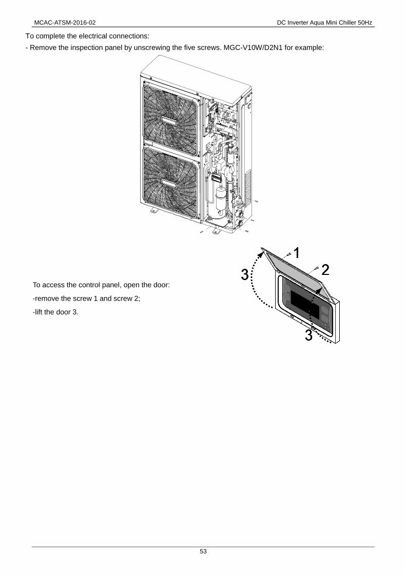
MCAC-ATSM-2016-02 DC Inverter Aqua Mini Chiller 50Hz
53
To complete the electrical connections:
- Remove the inspection panel by unscrewing the five screws. MGC-V10W/D2N1 for example:
To access the control panel, open the door:
-remove the screw 1 and screw 2;
-lift the door 3.

DC Inverter Aqua Mini Chiller 50Hz MCAC-ATSM-2016-02
54
17. Running and Maintenance
17.1 Operating characteristics
Set point in cooling mode
(Factory set) = 12°C, Hysteresis = 3°C.
The compressor starts with water temperatures above 12°C.
The compressor shuts down with water temperatures of less than 9°C.
Set point in heating mode
(Factory set) = 40°C, Hysteresis = 4°C.
The compressor starts with water temperatures below 38°C.
The compressor shuts down with water temperatures above 42°C.
In the event of a temporary power failure, when power returns, the mode set previously will be retained in the
memory.
Compressor start up delay
- Minimum time since last start-up 300 seconds.
Two functions prevent the compressor from starting up too frequently
Pump
The electronic board includes a pump control output. The pump starts when the assembly is powered up
and at least 285 seconds before the compressor starts up and stops 120 seconds after the assembly shuts
down. After the first 120 seconds of pump operation when the water flow is at full speed, the water flow
alarm functions are activated (differential pressure switch and flow switch). With a pump connected to
terminals PL and PN on the installer terminal board.
Fan speed control
For correct operation of the unit with different outside temperatures, the microprocessor controls the fan
speed based on the pressure reading from the pressure probe, thus enabling heat exchange to be increased
and/or decreased, maintaining the condensing or evaporation temperature practically constant.
The fan functions independently of the compressor.
Frost prevention alarm
To prevent the water freezing and damaging the plate heat exchanger, the microprocessor shuts down the
compressor if the temperature measured by the heat exchanger outlet temperature sensor is less than 3°C.
The frost prevention temperature set point can be modified by an authorized service center only and only
after verifying that the water circuit contains antifreeze. Tripping of this alarm shuts down the compressor but
not the pump, which remains active. To reset normal functions, the outlet water temperature must rise to
more than +15°C. Reset is manual.
Water flow alarm
The microprocessor provides for management of a water flow alarm controlled by a differential pressure
switch fitted as standard on the appliance to be installed on the water delivery piping.
This safety device may trip after the first 120 seconds of pump operation when the water flow is up to speed.
Tripping of this alarm shuts down the compressor but not the pump, which remains active. To reset normal
functions, the alarm contact must be deactivated for at least 15 seconds.
When electrical current exceeds to setting value and condenser temperature over than 62°C, system will
shut down, but not returns to normal operation until the condenser temperature decreased less than 52°C.
MCAC-ATSM-2016-02 DC Inverter Aqua Mini Chiller 50Hz
55
17.2 Routine maintenance
Never perform any cleaning operations before having disconnected the unit from the mains power supply.
If the supply cord is damaged, it must be replaced by the manufacturer or its service agent or a similarly
qualified manufacturer or its service agent or a similarly qualified.
Regular maintenance is fundamental to maintain the efficiency of the unit both in terms of operation and
energy consumption. The Technical Assistance Service maintenance plan must be observed, with an
annual service which includes the following operations and checks:
- Filling of the water circuit.
- Presence of air bubbles in the water circuit.
- Efficiency of safety devices.
- Power supply voltage.
- Power input.
- Tightness of electrical and hydraulic connections.
- Condition of the compressor contactor.
- Efficiency of the plate heat exchanger heater.
- Checking of operating pressure, superheating and sub cooling.
- Efficiency of compressor heater.
- Cleaning of finned coil (*).
- Cleaning of fan grills.
- Cleaning of condensate drain pan (if installed).
(*) For “Heat pump” appliances, the checks are to be performed quarterly.
For units installed near the sea, the intervals between maintenance should be halved.
17.3 Extraordinary maintenance
Never perform any cleaning operations before having disconnected the unit from the mains power supply.
Chemical washing
You are recommended to chemically wash the plate heat exchanger after every 3 years of operation.
Refrigerant gas content
The chillers are filled with R410a refrigerant gas and tested in the factory. In normal conditions, there should
be no need for the Technical Assistance Service to intervene to check the refrigerant gas. However, over
time, small leaks may develop at the joints leading to loss of refrigerant and draining of the circuit, causing
the unit to function poorly. In this case, the leaks of refrigerant must be identified and repaired and the
refrigerant circuit refilled. Proceed as follows:
- Empty and dry the entire refrigerant circuit using a vacuum pump connected to the low and high
pressure tap until the vacuum meter reads about 10Pa. Wait a couple of minutes and check that this value
does not rise to more than 200Pa.
- Connect the refrigerant gas cylinder or a filling cylinder to the low pressure line pressure gauge
connection.
- Fill with the quantity of refrigerant gas indicated on the rating plate of the unit.
- Always check the superheating and sub cooling values. In the nominal operating conditions for the
appliance, these should be between 5 and 10°C and between 4 and 8°C respectively.
- After a couple of hours of operation, check that the liquid indicator indicates circuit dry (dry-green).

DC Inverter Aqua Mini Chiller 50Hz MCAC-ATSM-2016-02
56
Important
In the event of partial leaks, the circuit must be completely emptied before being refilled.
The R410a refrigerant must only be filled in the liquid state. Operating conditions other than nominal
conditions may produce considerably different values.
Seal testing or identification of leaks must only be carried out using R410a refrigerant gas, checking with a
suitable leak detector.
Prohibition
1. The refrigerant circuit must not be filled with a refrigerant other than that indicated of specification.
2. The use of a different refrigerant may cause serious damage to the compressor.
3. Oxygen, acetylene or other inflammable or poisonous gases must never be used in the refrigerant
circuit as they may cause explosion or poisoning.
4. Oils other than those indicated on manual before must not be used. The use of different oils may cause
serious damage to the compressor.
17.4 Shutting down for long periods
If it is previewed not to use the machine for long periods
After deactivating the chiller:
-Make sure the model is in the power off model " ", or alternatively disconnect the unit from the power
supply.
-Make sure the remote control switch is closed (if present) .
-Close the water valves.
Important
If there is a possibility that the outside temperature may drop below zero, there is the risk of freezing.
The water circuit MUST BE EMPTIED AND SHUT OFF POWER (when draining after heat pump operation
take care as the water may be hot) or antifreeze must be added in the proportion recommended by the
manufacturer.
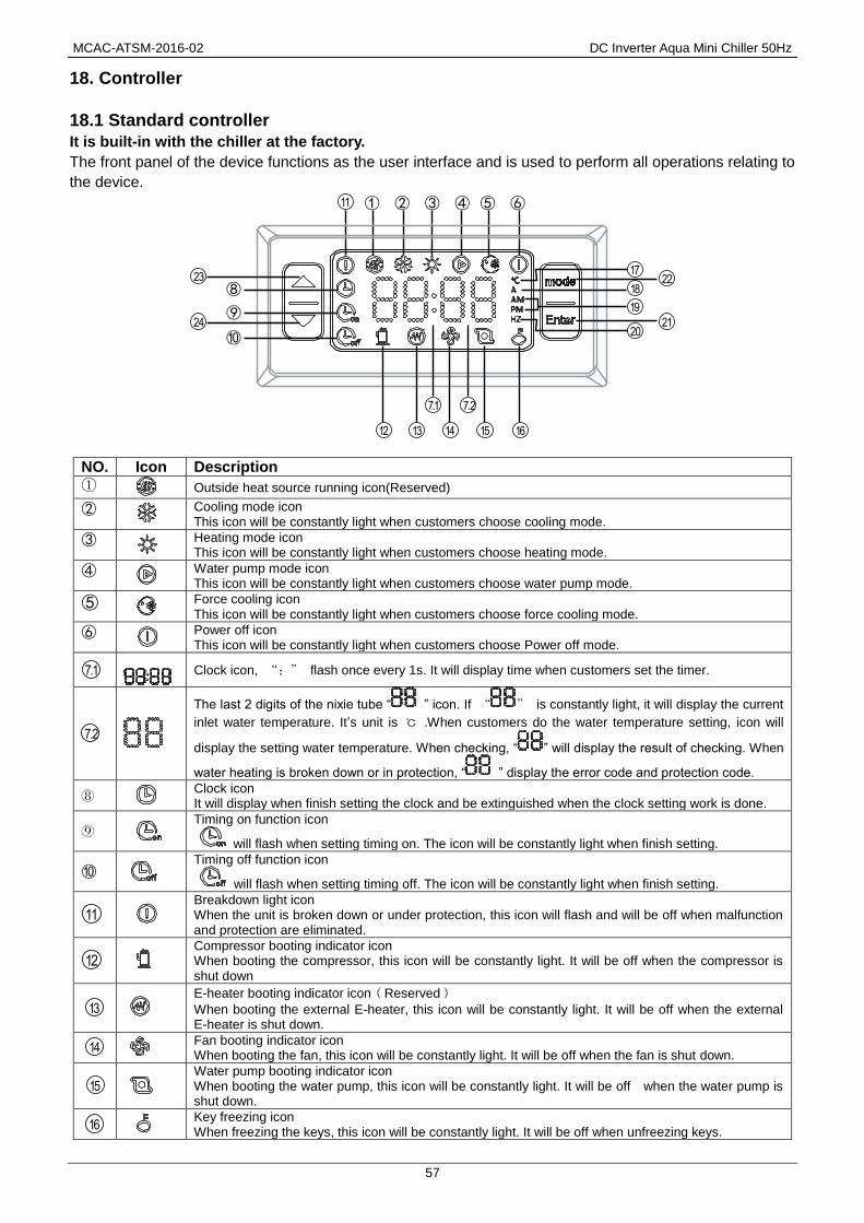
MCAC-ATSM-2016-02 DC Inverter Aqua Mini Chiller 50Hz
57
18. Controller
18.1 Standard controller
It is built-in with the chiller at the factory.
The front panel of the device functions as the user interface and is used to perform all operations relating to
the device.
NO. Icon Description
① Outside heat source running icon(Reserved)
②
Cooling mode icon This icon will be constantly light when customers choose cooling mode.
③
Heating mode icon This icon will be constantly light when customers choose heating mode.
④
Water pump mode icon This icon will be constantly light when customers choose water pump mode.
⑤
Force cooling icon This icon will be constantly light when customers choose force cooling mode.
⑥
Power off icon This icon will be constantly light when customers choose Power off mode.
Clock icon, “:” flash once every 1s. It will display time when customers set the timer.
The last 2 digits of the nixie tube “ ” icon. If “ ” is constantly light, it will display the current
inlet water temperature. It’s unit is ℃ .When customers do the water temperature setting, icon will
display the setting water temperature. When checking, “ ” will display the result of checking. When
water heating is broken down or in protection, “ ” display the error code and protection code.
⑧ Clock icon It will display when finish setting the clock and be extinguished when the clock setting work is done.
⑨
Timing on function icon
will flash when setting timing on. The icon will be constantly light when finish setting.
⑩
Timing off function icon
will flash when setting timing off. The icon will be constantly light when finish setting.
Breakdown light icon When the unit is broken down or under protection, this icon will flash and will be off when malfunction and protection are eliminated.
Compressor booting indicator icon When booting the compressor, this icon will be constantly light. It will be off when the compressor is shut down
E-heater booting indicator icon(Reserved)
When booting the external E-heater, this icon will be constantly light. It will be off when the external E-heater is shut down.
Fan booting indicator icon When booting the fan, this icon will be constantly light. It will be off when the fan is shut down.
Water pump booting indicator icon When booting the water pump, this icon will be constantly light. It will be off when the water pump is shut down.
Key freezing icon When freezing the keys, this icon will be constantly light. It will be off when unfreezing keys.
①
⑧
⑨
⑩
② ③ ④ ⑤ ⑥
7.1
12 13 14 15 16
17
18
11
7.2
19
2024
23
21
22
7.1
7.2
11
12
13
14
15
16

DC Inverter Aqua Mini Chiller 50Hz MCAC-ATSM-2016-02
58
Temperature unit icon When the control panel displays temperature, this icon will be constantly light.
Current unit icon When the control panel displays current, this icon will be constantly light.
Time format icon
The unit is 12-hour format. “ ”will be constantly light when it is forenoon.
“ ” will be constantly light when it is afternoon
Frequency unit icon It will be constantly light when the control panel displays frequency of the compressor.
ON/OFF and OK button
1. Long press “ ” for 3S will power on or off the controller.
2. Press “ ” to confirm the former operation when finishing the setting work.
Mode choice function/Function choice/Back function button 1. Mode choice function. Choose operation mode. 2. Function choice. Long press it for 3s to enter function setting in the main interface.(Clock setting, Timing on and timing off setting) 3. Back to the previous menu. Long press it for 3s to back to previous menu in the function setting interface. Top menu is the main interface.
Up 1.(Value increase) 2. Forward to the previous interface.
Down 1.(Value decrease) 2. Backward to the next interface.
18.1.1 Control panel operation description
1) ON/OFF
The first time to power on the unit, operation panel displays “OFF”. Long press “ ” for 3s to unlock “OFF”
status and enter into standby status.
Power on: In the standby status, press “ ” to enter mode choice function. Press “ ” circularly to
choose one kind of “power on” mode, the mode icon will flicker at the moment. Press “ ” to confirm the
power on mode. The unit will run as the chosen mode when the mode icon will be constantly light.
Power off: Press “ ” in the main interface to enter mode choice function and the icon which indicate
the current mode will flicker. Press “ ” circularly to choose power off mode,
“ ” will flicker at this moment. Press “ ” button to confirm the power off mode. By this time, “ ”
will be constantly light and the unit stops.
2) Mode choice and temperature settings
Press “ ” in the main interface to enter mode choice function. The “Mode” icon will flicker. Click
“ ” circularly to choose a mode. The circulating order is “Cooling mode”→“Heating mode”→“Water
pump mode” →“Power off mode” → “Cooling mode. The chosen mode will flicker. Press “ ”or “ ”
to increase/decrease the temperature in the chosen mode.
Press “ ” to confirm power off mode and the set temperature. Mode icon will be constantly light and the
unit will run as the chosen mode. Press “ ” or “ ” in the main interface to increase/decrease the
temperature in the chosen mode.
3) Clock setting
Long press “ ” for 3s to enter function interface. “ ” clock icon will flicker. Press “ ” to enter
clock setting function. “ ” icon will be constantly light and the first 2 digits on nixie tube will flicker. Press
“ ” or “ ” to set minute. Press “ ” when finish setting and “ ” will be extinguished.
4) Timing setting
a. Timing on setting
① Long press“ ”for 3s to enter function interface. “ ” clock icon will flicker. Press “ ”again
to enter timing on function. “ ” will flicker and press “ ” to enter timing on setting.
17
18
19
20
21
22
23
24

MCAC-ATSM-2016-02 DC Inverter Aqua Mini Chiller 50Hz
59
② At this moment, last 2 digits of the nixie tube display “01” which means the first group setting begins.
Press “ ” to the next step.
③ By this time, mode icon will flicker and press “ ”to choose timing on mode. Press “ ” to
confirm your choice and go to the next step.
④ By this time, the last 2 digits of the nixie tube will flicker and press “ ” or “ ” to adjust
temperature and set the temperature of the inlet water. Press “ ” to confirm and move to the next step.
⑤ By this time, the first 2 digits of the nixie tube will flicker and press “ ” or “ ” to adjust time of
timing on. Press “ ” to confirm and switch to minute setting automatically. The last 2 digits of the
nixie tube will flicker and press “ ” or “ ” to adjust minute setting of timing on.(minimal unit of minute
adjustment: 15 minutes) .
⑥ Press “ ” to confirm. The first group setting is finished and “ ” will be constantly light.
When processing the second timing setting, repeat the 1-2 operation above. When the nixie tube displays
“01” and flicker, press“ ” or “ ” to choose the timing on group. When the nixie tube displays “ 02 ”
which means setting timing on function of the second group.
Refers the timing on setting operation of group 1 to set that of group 2.
Long press “ ” for 3s to return to the previous interface to reset the parameter during setting clock
timing.
b. Timing off setting
① Long press “ ” for 3s in the main interface to enter function interface. Press “ ” circularly to
enter timing off function. “ ” will flicker and press “ ” to enter timing off setting.
② At this moment, the last 2 digits of the nixie tube display “01” which means the first group setting begins.
Press “ ” to the next step.
③ By this time, the first 2 digits of the nixie tube will flicker and press “ ” or “ ” to adjust time of
timing off. Press “ ” to confirm and switch to minute setting automatically. The last 2 digits of the nixie
tube will flicker and press “ ” or “ ” to adjust minute setting of timing off. Press “ ” to confirm.
The first group setting is finished and “ ” will be constantly light.
④ When processing timing setting of group 2, repeat the 1-2 operation above. When the nixie tube
displays “01” and flicker, press “ ” or “ ” to choose the timing off group. When the nixie tube displays
“02”which means setting timing off function of the second group.
Refers the timing off setting operation of group 1 to set that of group 2.
c. Cancel all timing on/off settings
Long press “ ” for 3s to enter function interface. “ ” clock icon will flicker and press “ ” to
choose the timing function. “ ” and “ ” flicker simultaneously means choosing to cancel all timing
functions.
Press “ ” to cancel timing settings. “ ” and “ ” both will be extinguished.
18.1.2 Functions of combination key
Force cooling function
Press “ ” and “ ” simultaneously for 3s in the main interface to enter into force cooling mode.
The force cooling mode icon will be constantly light.
Press “ ” button and “ ” button simultaneously for 3s to quit force cooling mode. The unit will enter
power off mode automatically when quitting force cooling mode.
Parameter query function

DC Inverter Aqua Mini Chiller 50Hz MCAC-ATSM-2016-02
60
Press “ ” and “ ” simultaneously for 3s to enter into the interface of parameter query function.
At this moment, first 2 digits of the nixie tube “ ” will display sequence number and the last 2 digits
is specific parameters. Press “ ” or “ ” to query the relative parameters.
When enter the parameter query, it will quit automatically and return to the main interface. Press “ ”
and “ ” simultaneously to quit parameter query manually.
Checking content table (for control panel and wired controller check)
Order Contents
01 Frequency
02 Running mode: 0-Power off,1-water pump,2-cooling,3-heating,4-force cooling
03 Fan speed: 0-Shutdown,1~7-Fan speed.
04 Total capacity requirements. Capacity before revised(Force cooling displays 5)
05 The revised capacity requirements. (Force cooling displays 5)
06 Cooling/heating temp. setting.
07 T3 temperature value (Outlet temperature of outdoor heat exchanger)
08 T4 temperature value (Outdoor environment temperature)
09 Tp temperature Value (Discharge refrigerant temperature)
10 Tin temp. Value (Inlet water temperature)
11 Tout temp. Value (Outlet water temperature)
12 Tb1 temp. Value (Temperature 1 of heat plate)
13 Tb2 temp. Value (Temperature 2 of heat plate)
14 T6 temp. Value (Reserved , Cooling fin surface temperature)
15 Outdoor unit operation current
16 Power supply voltage AD value
17 Electronic expansion valve opening steps(Step number *8)
18 The last error cord
19 The second error cord
20 The first error cord
18.1.3 Auto-lock (unlock) function
If don’t operate the controller in 60s, the keyboard will lock automatically. Press “ ”and “ ” simultaneously for 3s to unlock. 18.1.4 Factory Reset
In main interface, long press “ ” for 3s, the unit will close and recovers to factory default mode. Display panel will display “OFF”.

MCAC-ATSM-2016-02 DC Inverter Aqua Mini Chiller 50Hz
61
18.2 Optional wired controller (KJR-120F/BMK-E, KJR-120F1/BMK-E) Features
Touch key operation; LCD displays operation parameters; Multiple timers; Real-time clock (battery life: 5~8
years).
18.2.1 Overview
①.Operation icon ⑨.Water temp.
②.Code area ⑩.ON/OFF Key
③.Setting temperature ⑪.Left Right Key
④.Timing On/Off ⑫.Confirm Key
⑤.Function Icon ⑬.Function key
⑥.Unit number ⑭.Add and Reduce key
⑦.Water Level Indication (reserved) ⑮.Cancel key
⑧.Clock ⑯.Mode key
1. Operation icon : Indicate unit ON and OFF status; the icon displays when the unit is on and does not
display when the unit is off;
2. Mode area: Indicate the main unit operating mode; details refer to its’ manual;
3. Setting temperature: 2 status can be displayed: ;
4. Timing ON/OFF indication : Indicate the timing information; details refers to page 10 of the
manual;
5. Function icon
1) : Displays when the unit controlled by remote switch;
2) : The conflict icon.
3) : Displays when the unit is needed. Press and hold “MODE” key for 3 seconds to cancel the icon
and timing will restart until next maintenance;
4) : The reserved icon. ;
5) : The reserved icon. ;
14 13
3
1
2
4
16
11
15
5
6
7
8
9
10
11
12(Press for 3sec tocancel timer)
(Press for 3sec tounlock)
MODE
FUNCTIONS

DC Inverter Aqua Mini Chiller 50Hz MCAC-ATSM-2016-02
62
6) : Displays when check function is on; details refers to the manual;
7) : Displays when ambient temperature is low which means the main unit need anti-freezing action;
8) : Displays when no key operation for 2 minutes and all keys are locked. Press and hold “OK” key for
3 seconds to unlock;
9) : Displays when error or protection occurs and means the unit need maintenance by professionals.
6The unit number: The user can set the number; details refer to page 16 of the manual;
7. Water level indication: The reserved icon;
8. Clock: Under normal status displays clock; Under timing setting displays the setting timing, details refer to
page 15 of the manual;
9. Water temperature: Under normal status display water temperature; Under water temperature setting
status displays the setting value; Under check status displays check parameter, details refer to Page 9, 18 of
the manual;
10. ON/OFF key: Turn on and turn off functions, details refer to page 7 of the manual.
11. Right and Left key: Press these keys to check setting water temperature; Press right key to shift to the
next step setting under timing setting status; Press these keys to turn over the unit parameter information
under check status;
12. OK key: Press this key to confirm settings. Press and hold this key for 3 seconds to unlock under
locking status;
13. Function key: Setting water temperature, timing and clock etc., details refer to Page 9-17; Press and hold
this key for 3 seconds to enter check status, details refer to page 18 of the manual;
14. Add and Reduce key: Move up or move down values of temperature, timing etc;
15. Cancel key: Press this key to cancel parameter setting under setting status; Press and hold this key for 3
seconds to cancel timing when timing is valid;
16. Mode key: Power on the cooling function, heating function or water pump function, details refer to Page
8 of the manual.
18.2.2 Operation instructions
a. Turn On and Turn Off the main unit
1) Press the On/Off key to control On and Off status of the main unit.
2) Under Off status, press the On/Off key “ ” to run the main unit, at that time the LCD of wired controller
will display the operation icon “ ”. The main unit will running as the current setting of the wired controller.
3) Under On status, press the On/Off key “ ” to turn off the main unit and the operation icon “ ” on the
LCD will disappear.

MCAC-ATSM-2016-02 DC Inverter Aqua Mini Chiller 50Hz
63
b. Setting operating mode and function parameters
1) Setting operating mode and water temperature
Setting operating mode: Press “MODE” key to choose operation mode. The setting mode will change as the
following order each time the key is pressed:
Press “OK” key or wait for 7 seconds to confirm. During the setting process, pressing the “CANCEL” key to
exit without saving.
2) Setting water temperature:
Method 1: Press the “▲” or “▼” to adjust the water temperature after the controller is powered on. Press
“OK” key or wait for 7 seconds to confirm.
Method 2: Setting water temperature in parameters function. Press “FUNCTIONS” key under main
interface once to enter water temperature setting interface. Press the “▲” or “▼” to adjust the water
temperature .Press “OK” key or wait for 7 seconds to confirm.
Water temperature setting check: To check the water temperature setting value, press the “ ” or “ ”key
under the main page(the page displayed after the controller is powered on).
→ →Cooling Heating Water pump
▲
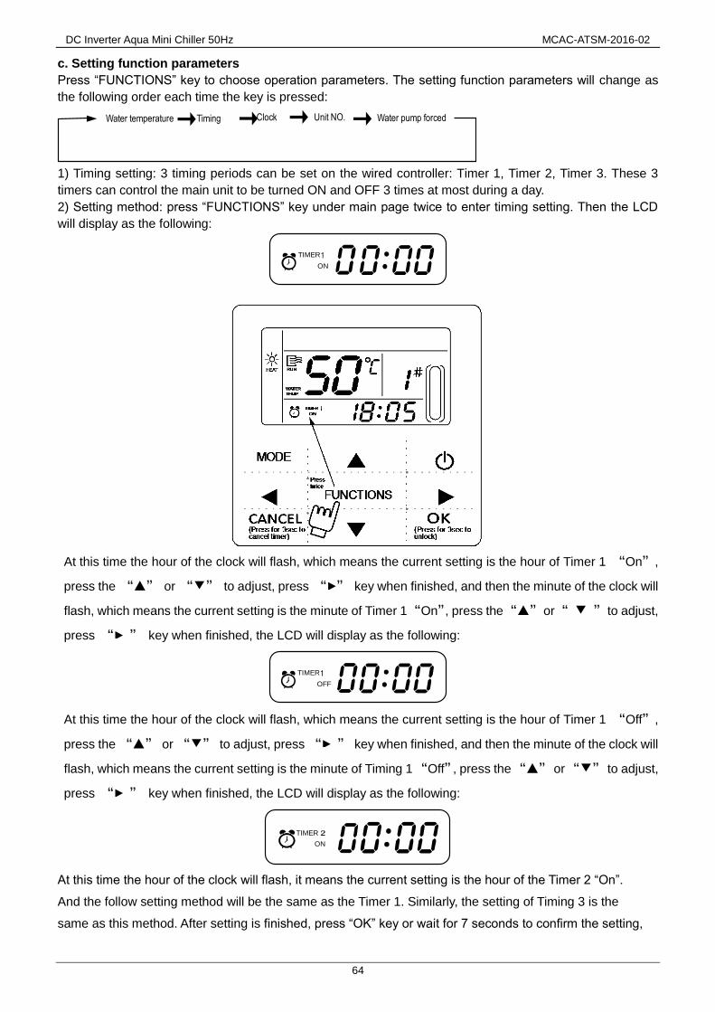
DC Inverter Aqua Mini Chiller 50Hz MCAC-ATSM-2016-02
64
c. Setting function parameters
Press “FUNCTIONS” key to choose operation parameters. The setting function parameters will change as
the following order each time the key is pressed:
1) Timing setting: 3 timing periods can be set on the wired controller: Timer 1, Timer 2, Timer 3. These 3
timers can control the main unit to be turned ON and OFF 3 times at most during a day.
2) Setting method: press “FUNCTIONS” key under main page twice to enter timing setting. Then the LCD
will display as the following:
At this time the hour of the clock will flash, which means the current setting is the hour of Timer 1 “On”,
press the “▲” or “▼” to adjust, press “ ” key when finished, and then the minute of the clock will
flash, which means the current setting is the minute of Timer 1 “On”, press the “▲” or “ ▼ ” to adjust,
press “ ” key when finished, the LCD will display as the following:
At this time the hour of the clock will flash, which means the current setting is the hour of Timer 1 “Off”,
press the “▲” or “▼” to adjust, press “ ” key when finished, and then the minute of the clock will
flash, which means the current setting is the minute of Timing 1 “Off”, press the “▲” or “▼” to adjust,
press “ ” key when finished, the LCD will display as the following:
At this time the hour of the clock will flash, it means the current setting is the hour of the Timer 2 “On”.
And the follow setting method will be the same as the Timer 1. Similarly, the setting of Timing 3 is the
same as this method. After setting is finished, press “OK” key or wait for 7 seconds to confirm the setting,
→ →Water temperature Timing Clock Unit NO.→ Water pump forced→
1TIMER
ON
▲
▲
1TIMER
OFF
▲
▲
TIMER
ON

MCAC-ATSM-2016-02 DC Inverter Aqua Mini Chiller 50Hz
65
and the LCD will display the effective timing information, as the following display:
Example of Timing setting
During any period of timing setting to press “OK” key , the timing periods which have been set will be
effective (only if the “On” and “Off” of one timing period have been set, the setting is effective).
Check timing information: to check the timing which has been set, press “ ” or “ ” key under main page,
the “On” and “Off” time of Timer1, Timer 2 and Timer3 will be displayed in turns.
Cancel timing: press and hold “CANCEL” key for 3 seconds, then all the effective timing periods will be
cancelled.
Note: Correct: To avoid timing error, each period of timing should not be crossed. E.g.:
Correct:
Wrong:
TIMER
Yes
No
Yes
No
Main page
▼
Press “FUNCTIONS” key twice to enter hoursetting interface of “Timer 1 On”
▼▼
▼Press “ ” key to enter minute setting interface of
“Timer 1 On”, adjust the minute number to be 10
Press “ ” key to enter hour setting interface of
“Timer 1 Off”, adjust the hour number of “Timer 1
Off” to be 12
Press the “▲” or “▼” key to set the hour
number of “Timing 1 On” to be 07
Press “ ” key to enter minute setting interface of
“Timer 1 Off”, adjust the minute number to be 30
The setting steps of “Timer 2” and “Timer 3” are the same as “Timer 1”,
after setting all the settings then press “OK” key, the 3 timing periods will
be effective.
“Timer 1” setting
failed, after 7
seconds, the
page shift to the
main page.
Successfully set the On time of
“Timer 1” to be 07:10 and Off time
of “Timer 1 Off ” to be 12:30, then
back to the main page.
Finish setting the On time of
“Timer 1” to be 07:10 and Off
time to be 12:30, then enter the
setting of “Timer 2”.
Whether press “OK” key Whether press “ ” key
▲
5:00 8:00 10:00 12:00 18:00 22:00
TIMER 1 TIMER 2 TIMER 3
5:00 8:007:00 12:00
TIMER 2TIMER 1

DC Inverter Aqua Mini Chiller 50Hz MCAC-ATSM-2016-02
66
d. Setting clock
Press the“FUNCTION”key 3 times to enter clock setting. The hour of the clock will flash, which means the
current setting is the hour of the clock, press the “▲” or “▼” to adjust, press “ ” key when finished,
and then the minute of the clock will flash, it means the current setting is the minute of the clock, press the
“▲” or “▼” to adjust, press “ OK ” key when finished or wait for 7 seconds to confirm. During the
setting process pressing the “CANCEL” key to exit without saving.
NOTE: To get the correct timing On and timing Off time, please correctly set the clock!
e. Setting unit number
Press the “FUNCTIONS” key 4 times to enter the unit number setting. Press “▲” or “▼” to adjust
the unit number. press “ OK ”key when finished or wait for 7 seconds to confirm. During the setting
process pressing the “CANCEL” key to exit without saving. The setting value is 0-18.
▲

MCAC-ATSM-2016-02 DC Inverter Aqua Mini Chiller 50Hz
67
f. Force opening water pump
Press the “FUNCTIONS” key 5 times to force open the water pump. The water pump icon will flash.
Press “OK” key to confirm. During the setting process, pressing the “CANCEL” key to exit without saving.
Note:
a. Forcing water pump function is only limited to stand-by mode, others modes not response.
b. Under forcing water pump function, other settings will not responsible, except stopping
c. When communication disconnects, it will show E2 error in 2 minutes, the wired controller will
automatically cancel the forcing water pump function; while connected, the wired controller keeps
synchronizing with the unit( If forcing water pump function is still on-going, the controller keeping showing
its status).
d. The outdoor unit does not response after activating the forcing water pump function, (eg: forcing water
pump function cannot be activated under forcing heating in stand-by mode),the function will be
automatically stopped if it is not activated within 5 minutes.
18.2.3 Checking function
1) Check function allows the user to check all the operating parameters, error and protection information of
the unit.
2) Entering method: press and hold “FUNCTIONS” key for 3 seconds to enter check interface, as the figure
display:
3) Press “ ” or “ ” to check all the status information of the unit.
Check content when wired controller setting is 1. The checking content is the same as the control panel
checking (Check list in page 60).
▲
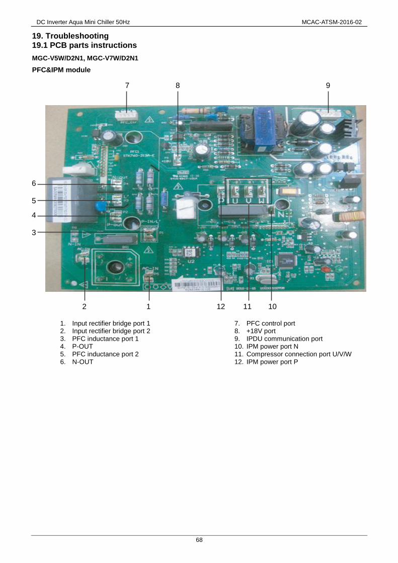
DC Inverter Aqua Mini Chiller 50Hz MCAC-ATSM-2016-02
68
19. Troubleshooting 19.1 PCB parts instructions
MGC-V5W/D2N1, MGC-V7W/D2N1
PFC&IPM module
1. Input rectifier bridge port 1 2. Input rectifier bridge port 2 3. PFC inductance port 1 4. P-OUT 5. PFC inductance port 2 6. N-OUT
7. PFC control port 8. +18V port 9. IPDU communication port 10. IPM power port N 11. Compressor connection port U/V/W 12. IPM power port P
7
6
5
4
3
2 1 12 11 10
8 9

MCAC-ATSM-2016-02 DC Inverter Aqua Mini Chiller 50Hz
69
Main control board
1. Power L 2. Power N 3. Preliminary charging relay (rectifier bridge input port 1) 4. Input rectifier bridge line (rectifier bridge input port 2) 5. 5A fuse 6. To IPDU 7. To PFC 8. Solenoid valve (Reserve) 9. Electric heater of plate heat exchanger 10. Electric heater of compressor 11. Pump 12. Electric heater of exhaust valve 13. Electric heater of water flow switch 14. 4-way valve 15. Additional pump/Boil (Reserve)
16. Transformer input 17. Electronic expansion valve 18. DC fan power supply port 19. DC fan port 20. Remote control 21. Force cooling switch 22. Parameter checking switch 23. Tin/Tout/Tb1 temperature sensor
24. Discharge temperature sensor (Tp) 25.1 Outlet of outdoor heat exchanger temperature sensor (T3) 25.2 Ambient temperature sensor(T4) 26.1 Low pressure switch 26.2 High pressure switch 27. Operation and display panel port 28. Water flow switch 29. Transformer output
4 3 2 1
2829
25.1
26.1
27
24
23
25.2
26.2
6
7
5
8
9
1011 12
13 14 16
1715 18 19 20
21
22

DC Inverter Aqua Mini Chiller 50Hz MCAC-ATSM-2016-02
70
DC filter panel
1. IPM Power supply N 2. IPM Power supply P 3. PFC output power P
4. PFC output power N 5. DC 380V (DC fan power supply port)
1
2
3
4
5

MCAC-ATSM-2016-02 DC Inverter Aqua Mini Chiller 50Hz
71
MGC-V10W/D2N1, MGC-V12W/D2N1 Main control panel
1. Transformer output port 2. Tin/Tb1/Tout/Tb2 temperature sensor port Note: Tin: water inlet temp. Tout: water outlet temp.
Tb1: Temp. 1 of plate heat exchanger Tb2: Temp.2 of plate heat exchanger
3. Radiator temperature sensor port(Reserved) (T6) 4. Discharge temperature sensor port 5.1 Outlet of outdoor heat exchanger temp. sensor port(T3) 5.2 Ambient temp. sensor port (T4) 6. Operation and display panel port 7.1 Low pressure switch 7.2 High pressure switch 8. Differential pressure valve port 9. Factory debug port 10. Wired controller port 11. Electric expansion valve port 12. Power supply input port L 13. Power supply input port N
14. Ground wire 15. Rectifier bridge input port N
16. Rectifier bridge input port L 17. 8A fuse tube 18. Solenoid valve port (Reserved) 19. Exhaust valve electric heater port 21. Plate heat exchanger electric heater 22. Differential pressure valve electric heater port 23. Built-in water pump port 24. Compressor electric heater 25. 4-way valve port 26. External pump/Remote alarm port 27. Transformer input port 38. P/N/+15V port 29. Communication port between IPDU and main PCB 30. Down DC fan port 31. Check touch switch 32. Up DC fan port 33. Force-cooling touch switch
1
2
3 4
5.1 5.2
6 7.1
7.2 8
9
10
11
12
13
14
15
16
17
18
19
20
21
22
23
24
25
26
27 28 29
30 31 32
33
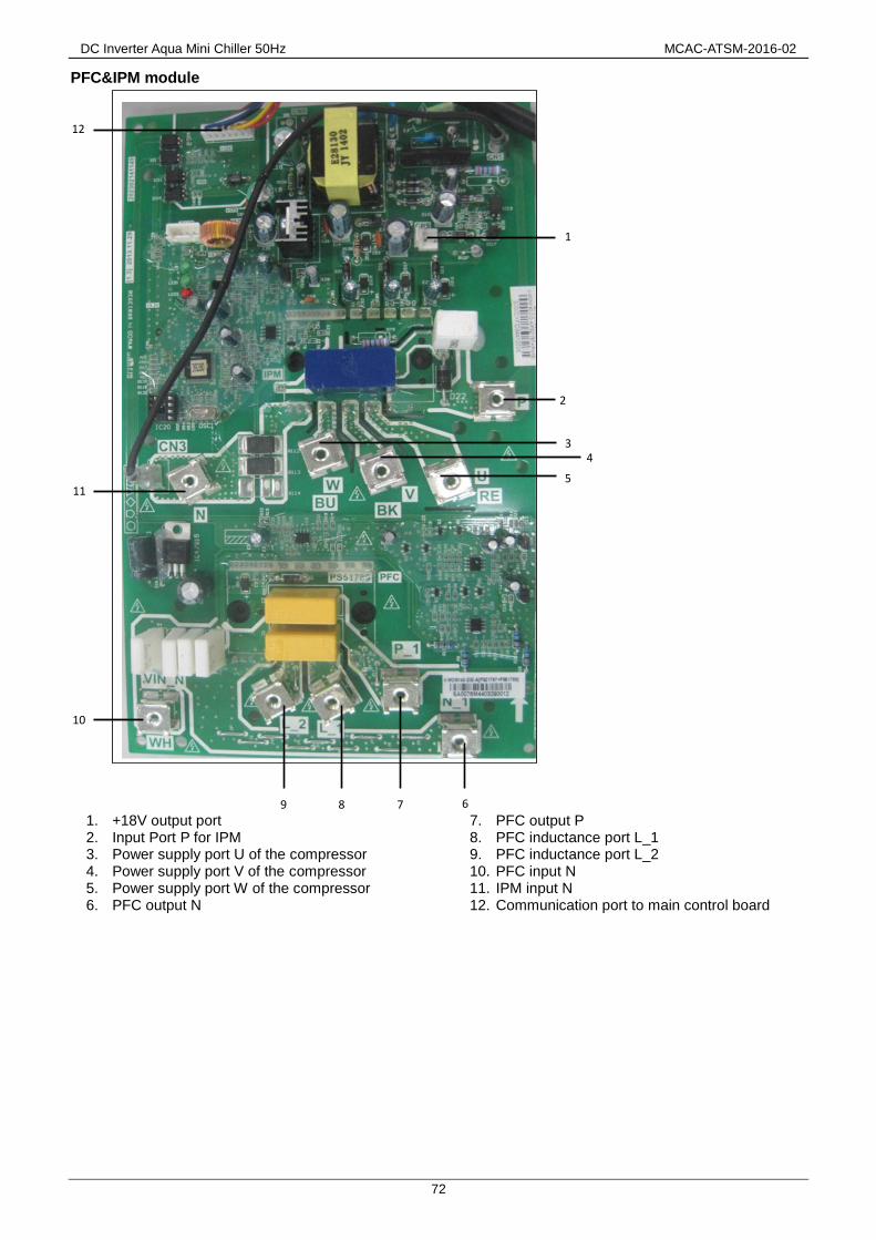
DC Inverter Aqua Mini Chiller 50Hz MCAC-ATSM-2016-02
72
PFC&IPM module
1. +18V output port 2. Input Port P for IPM 3. Power supply port U of the compressor 4. Power supply port V of the compressor 5. Power supply port W of the compressor 6. PFC output N
7. PFC output P 8. PFC inductance port L_1 9. PFC inductance port L_2 10. PFC input N 11. IPM input N 12. Communication port to main control board
2
1
3 4
5
6 7 8 9
10
11
12

MCAC-ATSM-2016-02 DC Inverter Aqua Mini Chiller 50Hz
73
MGC-V12W/D2RN1, MGC-V14W/D2RN1&MGC-V16W/D2RN1 Main control board
1. Input port for switching power supply
2. Debugging port
3. Connection port for operation and display panel
4. Tin/Tb1/Tout/Tb2 temp. sensor port
Note: Tin: water inlet temp. Tout: water outlet temp.
Tb1: Temp.1 of plate heat exchanger
Tb2: Temp. 2 of plate heat exchanger
5. Discharged temperature sensor port (Tp)
6.1 T3 temperature sensor port
6.2 T4 ambient temperature sensor port
7.1. Low pressure switch
7.2 High pressure switch
8. Checking touch switch
9. Force-cooling touch switch
10. Differential pressure valve port
11. Factory debugging port
12. Wired controller port
13. AC Current transformer
14.”Remote on/off” and “remote cooling/heating”
port
15. Electronic expansion valve port
16. AC 220V power supply port
17. Solenoid valve port (Reserved)
18. Exhaust valve electric heater port
2
1
3
4
5 6.1
6.2 7.1
7.2 10
11
14
16
17
18
19
20
21
22
23
24
25
26
27
28
29
15 13
230
12
8 9

DC Inverter Aqua Mini Chiller 50Hz MCAC-ATSM-2016-02
74
19. Electric heater port of Plate heat exchanger
20. Electric heater port of differential pressure valve
21. Built-in water pump port
22. Electric heater of the compressor
23. Precharge AC contactor port
24. 4-way valve port
25. External water pump/Remote alarm port
26. Up DC fan port
27. Down DC fan port
28. Power supply port for switching power supply of
PFC board
29. Drive module port
30. P/N/+15V port
IPM module
1. +15V output port
2. communication port to main control board
3. IPM input port N
4. Compressor connection port W
5. Compressor connection port V
6. Compressor connection port U
7. IPM input P
8. Power supply port for switching power supply
2
8
3 4 5 6 7
1
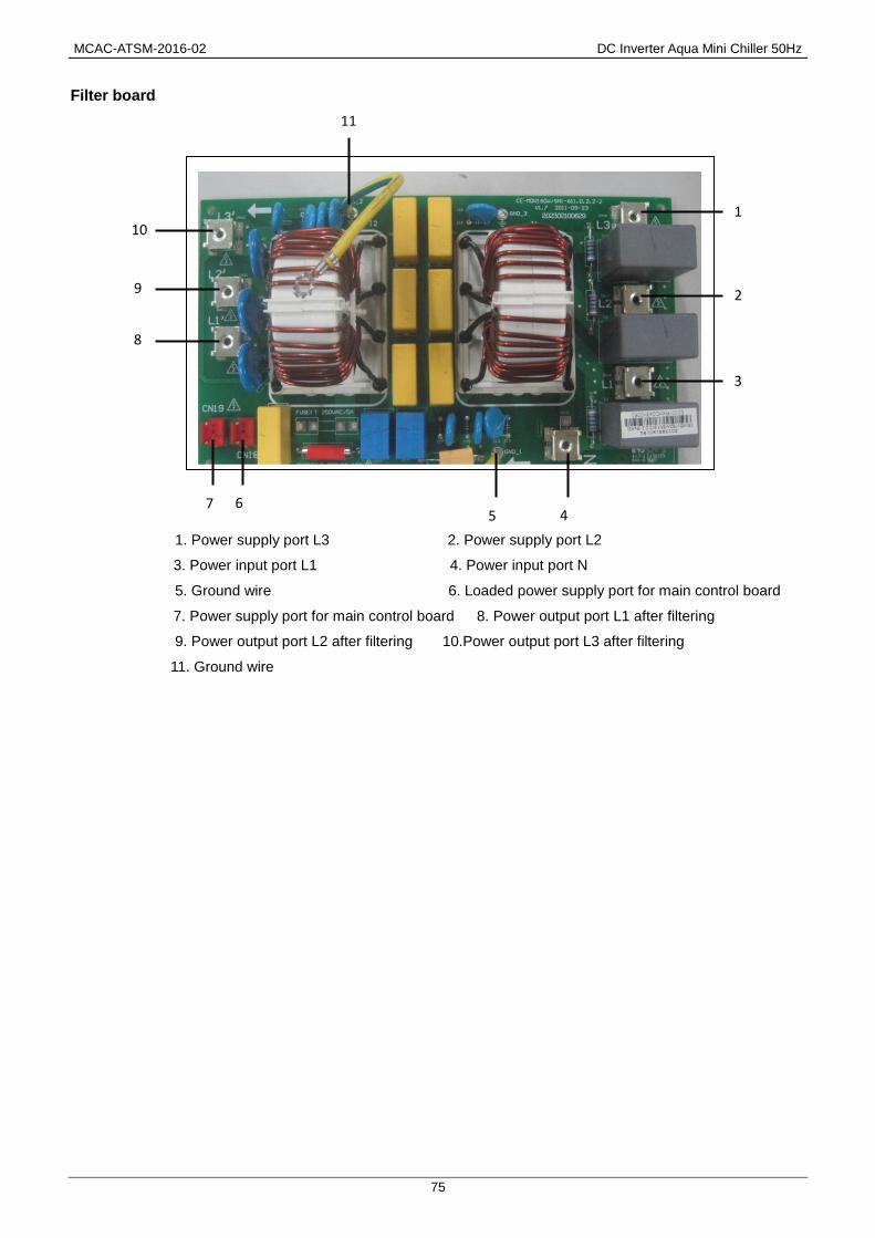
MCAC-ATSM-2016-02 DC Inverter Aqua Mini Chiller 50Hz
75
Filter board
1. Power supply port L3 2. Power supply port L2
3. Power input port L1 4. Power input port N
5. Ground wire 6. Loaded power supply port for main control board
7. Power supply port for main control board 8. Power output port L1 after filtering
9. Power output port L2 after filtering 10.Power output port L3 after filtering
11. Ground wire
2
10
4 7
1
3
6 5
9
8
11

DC Inverter Aqua Mini Chiller 50Hz MCAC-ATSM-2016-02
76
19.2 Function setting dial switches instructions
For 5/7kW
For 10kW
For 12-16kW
19.3. Query function for PCB checking switch
Press checking touch switch on PCB to check the parameters. The check list on PCB is in table below.
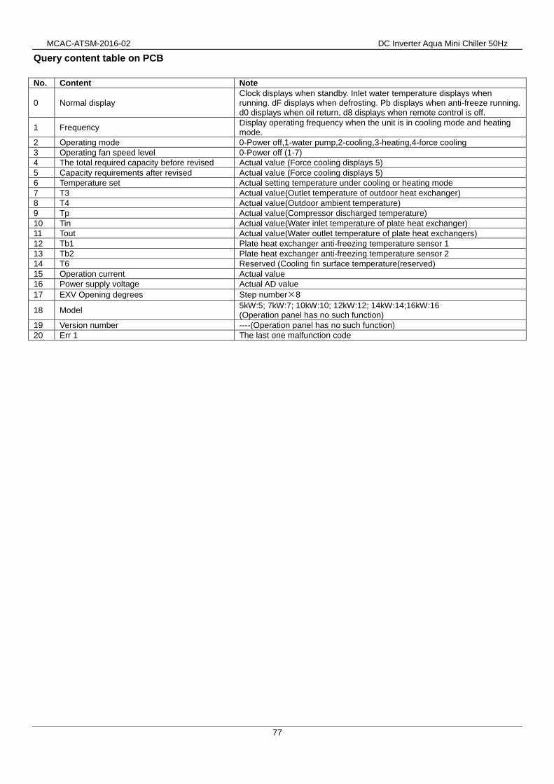
MCAC-ATSM-2016-02 DC Inverter Aqua Mini Chiller 50Hz
77
Query content table on PCB
No. Content Note
0 Normal display Clock displays when standby. Inlet water temperature displays when running. dF displays when defrosting. Pb displays when anti-freeze running. d0 displays when oil return, d8 displays when remote control is off.
1 Frequency Display operating frequency when the unit is in cooling mode and heating mode.
2 Operating mode 0-Power off,1-water pump,2-cooling,3-heating,4-force cooling
3 Operating fan speed level 0-Power off (1-7)
4 The total required capacity before revised Actual value (Force cooling displays 5)
5 Capacity requirements after revised Actual value (Force cooling displays 5)
6 Temperature set Actual setting temperature under cooling or heating mode
7 T3 Actual value(Outlet temperature of outdoor heat exchanger)
8 T4 Actual value(Outdoor ambient temperature)
9 Tp Actual value(Compressor discharged temperature)
10 Tin Actual value(Water inlet temperature of plate heat exchanger)
11 Tout Actual value(Water outlet temperature of plate heat exchangers)
12 Tb1 Plate heat exchanger anti-freezing temperature sensor 1
13 Tb2 Plate heat exchanger anti-freezing temperature sensor 2
14 T6 Reserved (Cooling fin surface temperature(reserved) 15 Operation current Actual value 16 Power supply voltage Actual AD value 17 EXV Opening degrees Step number×8
18 Model 5kW:5; 7kW:7; 10kW:10; 12kW:12; 14kW:14;16kW:16 (Operation panel has no such function)
19 Version number ----(Operation panel has no such function)
20 Err 1 The last one malfunction code

DC Inverter Aqua Mini Chiller 50Hz MCAC-ATSM-2016-02
78
19.4 Error code table
5/7kW
Error Code
Content Note
E9 EEPROM malfunction
The same as 10-16kW
H0 Communication malfunctions between main chip and IPDU.
E4 T3,T4 sensor malfunction
E5 Voltage protection malfunction
E6 DC fan motor malfunction
EA A fan in the A region run for more than 5 minutes in heating mode
Eb There are two times E6 fault in 10 minutes (recovery after power off)
HH Inlet water temperature sensor malfunctions for 5/7kW models.
5/7kW EC Outlet water temperature sensor malfunction (5/7kW)
C0 Temperature sensor malfunction of plate heat exchanger for 5/7kW.
P1 High pressure protection
The same as 10-16kW
P2 Low pressure protection
P3 Current protection of the compressor
P4 Discharged temperature protection
P5 T3 high temperature protection of outdoor condenser
P6 IPDU module protection
P8 Typhoon protection
CH Protection when temperature difference between inlet & outlet water in heating mode is too large for 5/7kW
5/7kW CL Protection when temperature difference between inlet & outlet water in cooling mode is too large for 5/7kW.
CP Anti-freeze protection of plate heat exchanger for 5/7kW
Pb System anti-freeze protection The same as 10-16kW C8 Water flow switch protection malfunction
PH Protection when water temperature in heating mode is too high for 5/7kW. 5/7kW
dF Defrosting The same as 10-16kW d8 Remote control

MCAC-ATSM-2016-02 DC Inverter Aqua Mini Chiller 50Hz
79
10-16kW
Error Code Content Note
E9 EEPROM malfunction
The same as 5/7kW
H0 Communication malfunctions between main chip and IPDU.
E4 T3,T4 sensor malfunction
E5 Voltage protection malfunction
E6 DC fan motor malfunction
EA A fan in the A region run for more than 5 minutes in heating mode
Eb There are two times E6 fault in 10 minutes (recovery after power off)
C0 Inlet water temperature sensor malfunction for 10~16kW models.
10-16kW
C1 Outlet water temperature sensor malfunction (10-16kW)
F7 Sensor temperature 1 of plate heat exchangers for 10-16kW. F8 Sensor temperature 2 of plate heat exchangers for 10-16kW. PL Reserved for 10-16kW. P1 High pressure protection
The same as 5/7kW
P2 Low pressure protection
P3 Current protection of the compressor
P4 Discharged temperature protection
P5 T3 high temperature protection of outdoor condenser
P6 IPDU module protection
P8 Typhoon protection
CH Protection when water temperature is too high in heating mode.
10-16kW CL To low water temperature protection in heating mode for 10-16kW
CP Anti-idling protection for water pump
Pb System anti-freeze protection The same as 5/7kW
C8 Water flow switch protection malfunction
PH Protection when temperature difference between inlet water & outlet water is too large for 10-16kW. 10-16kW
dF Defrosting The same as 5/7kW
d8 Remote control

DC Inverter Aqua Mini Chiller 50Hz MCAC-ATSM-2016-02
80
19.5 Troubleshooting
19.5.1 E9
19.5.2 H0
E9: EEPROM error
Check whether EEPROM is correctly installed NO
Replace EEPROM
Replace PCB
H0: Unit communication error
Check whether module board and its signal wire is connected effectively
Reconnect wire No
Whether LED is flicker normally (green light) while power on
PCB is damaged, replace PCB No
Yes
Replace module board
Yes
Yes
PCB is damaged
EEPROM

MCAC-ATSM-2016-02 DC Inverter Aqua Mini Chiller 50Hz
81
19.5.3 E4, C0, C1, F7, F8 19.5.4 E5
Connection ports for temperature sensor on main PCB are loose or false connected
PCB is damaged
E4,C0,C1,F7,F8: Malfunction of temperature sensor
Fasten or reconnect the temperature sensor ports
Temperature sensor is short circuited or disabled (Use a multi-meter to measure resistance, if the resistance is too low, the sensor is short circuited, if the resistance in certain temperature is not consistent with appendix table, the sensor is disabled)
Yes
Replace the sensor
No
Yes
No
Replace PCB
E5: Malfunction of power supply voltage
Voltage of power supply is too high or too low, the normal voltage between L and N (single phase), A and N, B and N, C and N (there phase) should be 198V~252V
Yes Provide normal power
supply
No
PCB is damaged Replace PCB

DC Inverter Aqua Mini Chiller 50Hz MCAC-ATSM-2016-02
82
19.5.5 E6
The contents in are just for single phase units.
E6: Malfunction of outdoor unit DC fan motor
Refers to the wiring diagram to check whether the DC fan motor wiring is correct
NO Connect again
YES
Check voltage of the DC fan motor, the normal voltage between red and black terminal should be 277~ 354V when standby
YES
Normal voltage between DC fan motor’s white terminal and black terminal should be 15V when standby
No Replace IPM module
Yes
The outdoor DC fan starts after the indoor fan operates for 3 minutes
Check voltage of PFC module “+” and “-”, the normal voltage should be 277~ 354V
Replace PFC module
NO NO
YES
Yes
PCB is damaged
Replace PCB
No Voltage between DC fan motor’s black and black terminal is lower than 2.4V
No Replace DC fan motor
Yes
Fan motor terminal

MCAC-ATSM-2016-02 DC Inverter Aqua Mini Chiller 50Hz
83
19.5.6 P1
When the pressure is over 4.4MPa, the system will display P1 protection, the ODUs will be standby.
When the pressure is lower than 3.2MPa, P1 protection is finished and normal operation resumes.
Refers to the wiring diagram to check whether the high pressure switch is correctly connected
The wire of high pressure is broken or short circuit high pressure switch the system running normally
No Reconnect pressure switch
Low heat exchange efficiency, causes may include dirty heat exchanger, dirty plate type heat exchanger, abnormal fan operation, water pump error, too closed outdoors installation, etc.
Replace high pressure switch
The high pressure side of the system is blocked, caused by crushed or bent pipe, blocked filter or EXV, etc.
Inspect the system and fix the error
Yes
Yes
PCB is damaged
P1: High pressure protection
Yes Inspect the system and fix
the error
No
Yes
No
No
Replace PCB

DC Inverter Aqua Mini Chiller 50Hz MCAC-ATSM-2016-02
84
19.5.7 P2
When the pressure is lower than 0.14MPa, the system will display P2 protection, the ODUs will be standby.
When the pressure is higher than 0.30MPa, P2 protection finished and normal operation resumes.
Note:
* The phenomenon of insufficient refrigerant
Top temperature and discharge temperature of all compressors are higher than normal value, discharge pressure and suction
pressure are both lower than normal value, current is lower than normal value, suction pipe may be frosting. The entire phenomenon
will disappear after recharging refrigerant.
* The phenomenon of low pressure side blockage
The discharge temperature is higher than normal value, low pressure is lower than normal value, current is lower than normal value
and suction pipe may be frosting.
P2: Low pressure protection
Insufficient refrigerant caused by insufficient recharge or refrigerant leakage*
No
The low pressure side is blocked, caused by crushed or bent pipe, closed EXV, dirty filter, etc.*
Refers to the wiring diagram to check whether the high pressure switch is correctly connected
The wire of high pressure is broken or short circuit
high pressure switch the system running normally
Reconnect pressure switch
Replace high pressure switch
Yes
Yes
The ambient Temp. and water inlet Temp. is low
(ambient temperature lower than -5℃)
No
No
Stop the unit and wait for ambient temperature goes up
Yes
Yes Add refrigerant or inspect the
system for leaks
No
Yes Inspect the system and fix
the error
PCB is damaged Replace PCB
No

MCAC-ATSM-2016-02 DC Inverter Aqua Mini Chiller 50Hz
85
19.5.8 P3
When current is over the specific value (Single phase unit 5/7kW 18A, single phase unit 10/12kW 30A, three
phase unit 15A), the system will display P3 protection, the ODU in standby.
When the current goes back to normal range, P3 disappears and normal operation resumes.
P3: Over current protection
Check whether the input current is large than the specific value
Check whether the ambient temperature is too high
Yes
Low heat exchange efficiency, causes may include dirty heat exchanger, dirty plate type heat exchanger, abnormal fan operation, water pump error, too closed outdoors installation, etc.
No
Inspect the system and fix the error
The refrigerant pipe is block, caused by crushed or bent pipe, blocked EXV valve, blocked filter, etc.
PCB is damaged
PCB is damaged, replace PCB
No
Yes Stop the unit and wait for
ambient temperature get down
Yes
No
Replace PCB
Inspect the system and fix the error
Yes
No

DC Inverter Aqua Mini Chiller 50Hz MCAC-ATSM-2016-02
86
19.5.9 P4
When the discharge temperature is higher than 115°C, the system will display P4 protection, the ODUs will be
standby.
When the discharge temperature is lower than 83°C, P4 protection finished and normal operation resumes.
P4: Compressor discharge temperature protection
Check whether the discharge temperature is higher than 115°C
PCB is damaged
Replace PCB
Check whether the discharge temperature sensor is disabled
Check whether there is refrigerant leakage
Replace discharge temperature sensor
Yes
Yes Repair the leakage and
recharge refrigerant
No
Refers to the wiring diagram to check whether the discharge temperature sensor is correctly connected
Reconnect temperature sensor
Yes
No
Yes
No

MCAC-ATSM-2016-02 DC Inverter Aqua Mini Chiller 50Hz
87
19.5.10 P5 When condenser temperature is over 62
oC the system will display P5 protection, the ODUs will standby.
When the condenser temperature goes back to normal range, P5 protection finishes and normal operation
resumes.
P5: Condenser temperature protection
Check whether the condenser temperature is higher than 62°C
Check whether the condenser temperature sensor is incorrectly connected or disabled
The ambient temperature is higher than 48℃
No
Clean the heat exchanger
Stop the unit and wait for ambient temperature goes down
No Replace PCB
Reconnect or replace condenser temperature sensor
Yes
Yes
Yes
No
Yes
No
No
PCB is damaged
Replace PCB
Low heat exchange efficiency, causes may include dirty heat exchanger, dirty plate type heat exchanger, abnormal fan operation, water pump error, too closed outdoors installation, etc.
Inspect the system and fix the error
The refrigerant pipe is block, caused by crushed or bent pipe, blocked EXV valve, blocked filter, etc.
Inspect the system and fix the error
Yes
No
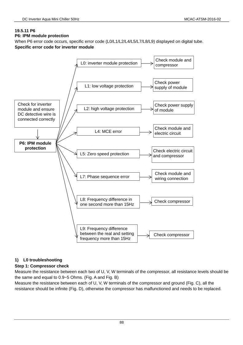
DC Inverter Aqua Mini Chiller 50Hz MCAC-ATSM-2016-02
88
19.5.11 P6 P6: IPM module protection
When P6 error code occurs, specific error code (L0/L1/L2/L4/L5/L7/L8/L9) displayed on digital tube.
Specific error code for inverter module
1) L0 troubleshooting
Step 1: Compressor check
Measure the resistance between each two of U, V, W terminals of the compressor, all resistance levels should be
the same and equal to 0.9~5 Ohms. (Fig. A and Fig. B)
Measure the resistance between each of U, V, W terminals of the compressor and ground (Fig. C), all the
resistance should be infinite (Fig. D), otherwise the compressor has malfunctioned and needs to be replaced.
L1: low voltage protection
L4: MCE error
L2: high voltage protection
L8: Frequency difference in one second more than 15Hz
L9: Frequency difference between the real and setting frequency more than 15Hz
L0: inverter module protection
L5: Zero speed protection
L7: Phase sequence error
P6: IPM module protection
Check module and compressor
Check power supply of module
Check power supply of module
Check module and electric circuit
Check electric circuit and compressor
Check module and wiring connection
Check compressor
Check compressor
Check for inverter module and ensure DC detective wire is connected correctly

MCAC-ATSM-2016-02 DC Inverter Aqua Mini Chiller 50Hz
89
Fig. A Fig.B Fig.C Fig.D
If the resistance values are normal, then go to step 2.
Step 2: Module check
1) DC voltage between terminal P and terminal N should be 1.41 times the local power supply voltage.
2) DC voltage between terminal 1 and 2 should be 510V~580V.
3) Disconnect the terminal 3, 4, and 5 from inverter compressor. Measure the resistance between any two
terminals among terminal 1, 2, 3, 4, and 5. All the values should be infinite. If any of the value approximates to 0,
the inverter module is damaged and should be replaced.
Then replace the inverter module.
P N
1 2 3 4 5
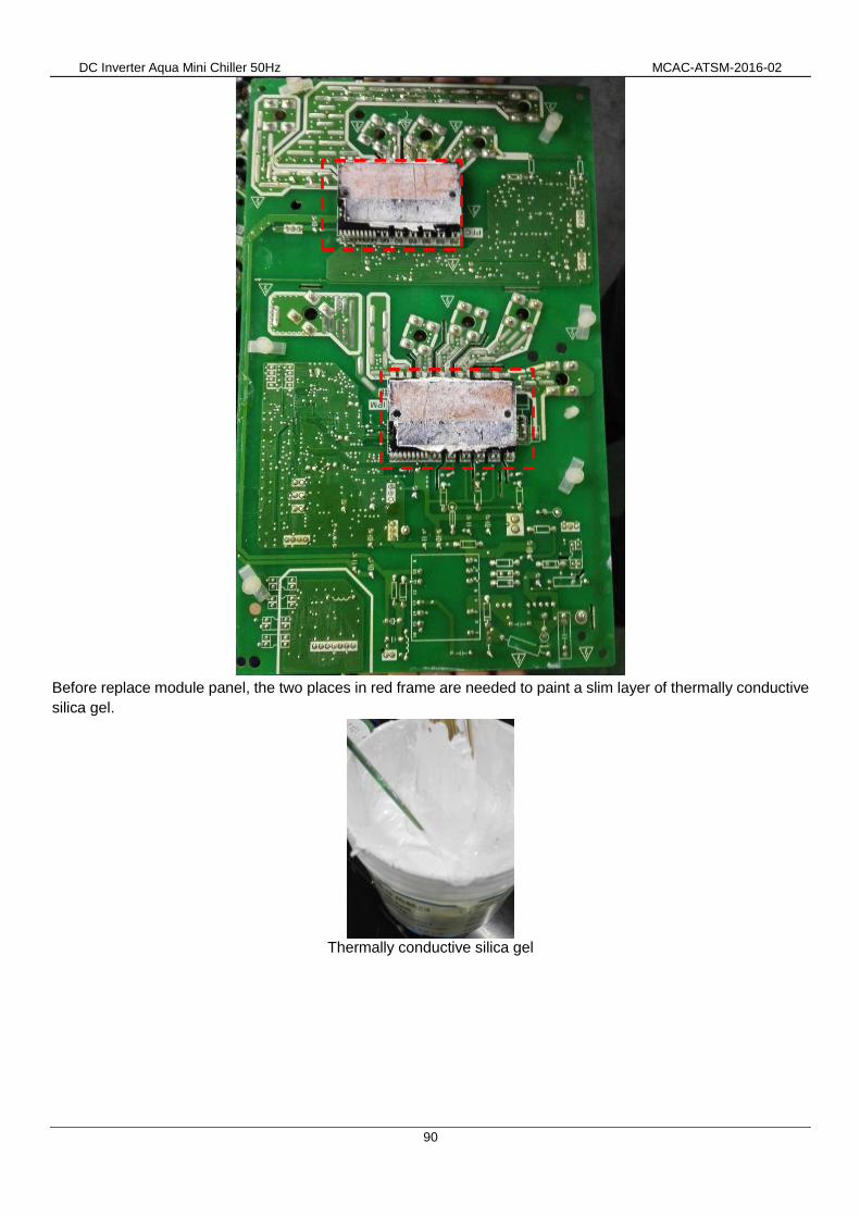
DC Inverter Aqua Mini Chiller 50Hz MCAC-ATSM-2016-02
90
Before replace module panel, the two places in red frame are needed to paint a slim layer of thermally conductive
silica gel.
Thermally conductive silica gel

MCAC-ATSM-2016-02 DC Inverter Aqua Mini Chiller 50Hz
91
Step 3: DC detective wire check (if the unit has change the PCB or reconnect the wire, the following item
should be checked)
Direction of the current in DC supply wire which is running through the inductor should be the same as the
direction of arrow marked on the inductor.
2) L1/L4 troubleshooting
Step 1: Check the DC voltage between terminal 1 and 2, the normal value should be 510V~580V, if the voltage is
lower than 510V, go to step 2.
Step 2: Check for rectifier wiring circuit. If wires are loose, fasten the wires. If wires are OK, replace the main
PCB.
1 2

DC Inverter Aqua Mini Chiller 50Hz MCAC-ATSM-2016-02
92
3) L2 troubleshooting
Step 1: Check the DC voltage between terminal 1 and 2, the normal value should be 510V~580V, if the voltage is
higher than 580V, go to step 2.
If the value is not in the range, this indicates a problem with the electrolytic capacitor power supply, check the power supply for high or unstable voltage. If the voltage value is normal, then the main PCB has malfunctioned, it needs to be replaced.
4) L8/L9 troubleshooting
Step 1: Compressor check
Measure the resistance between each two of U, V, W terminals of the compressor, all the resistance should be
the same and equal to 0.9~5 Ohms. (Fig. A and Fig. B)
Measure the resistance between each U, V, W terminal of the compressor and ground (Fig. C), all the resistance
should be infinite (Fig. D), if not the compressor has malfunctioned and needs to be replaced.
Fig. A Fig.B Fig.C Fig.D
If the resistance values are normal, then go to step 2.
Step 2: Disconncet the power wiring from the compressor, replace the main PCB of the unit and ensure correct
wiring, if compressor can start normally, it means the main PCB which was replaced was damaged. If compressor
still can’t start normally, replace the compressor.
Step 3: Replace the compressor
1 2

MCAC-ATSM-2016-02 DC Inverter Aqua Mini Chiller 50Hz
93
19.5.12. P8
P8:Typhoon protection
Check whether there is strong wind against outdoor fan
No
Check whether the outdoor fan is damaged
PCB is damaged
Yes
Clean the heat exchanger
Stop the unit and until there is no strong wind
Replace outdoor fan
Yes
No
Replace PCB

DC Inverter Aqua Mini Chiller 50Hz MCAC-ATSM-2016-02
94
19.5.13. PH
PH: Large temperature differential protection between water out and water in
Check whether actual temperature difference between water out and water in is large than14°C
No
Water in and water out temperature sensor are correctly connected and effectively
Yes
PCB is damaged.
Replace PCB
Correct connect the temperature sensor or replace temperature sensor
No Yes
The water flow rate is not sufficient
The water system is blocked
Yes
Check the system and fix the problem
No
The water pump speed is suitable
No Adjust water pump to high speed suitable
Yes
The additional water pump is not suitable selected
Select a suitable additional water pump

MCAC-ATSM-2016-02 DC Inverter Aqua Mini Chiller 50Hz
95
19.5.14 Pb
Pb: Anti-frozen protection
Detect actual temperature of inlet water or plate type heat exchanger: the detected temperature is lower
than 3℃ in cooling mode or detected temperature is
lower than 5℃ in heating mode and standby.
No
PCB is damaged
Its normal system protection, the system will resume when temperature go up
Yes
No
Check whether temperature sensor of water inlet pipe or plate type heat exchanger is not effectively connected or damaged
Yes Replace or reconnect
temperature sensor
Replace PCB

DC Inverter Aqua Mini Chiller 50Hz MCAC-ATSM-2016-02
96
19.5.15 C8&CP
C8: Water volume protection CP: Water volume protection in situation of anti-frozen protection
System water leakage
No
Water pipeline too long and need an additional water pump
Install a suitable additional water pump
Fix the leakage and affusion again
Yes
Yes
Water system is blocked Inspect the system and fix the problem
No Yes
The water pump is damaged
No
Yes Replace water pump
No
The water flow switch is damaged
Yes Replace water flow switch
No
PCB is damaged
Replace PCB

MCAC-ATSM-2016-02 DC Inverter Aqua Mini Chiller 50Hz
97
20. Accessories
Item Name of accessory Qty. Shape
1 Installation and operation manual 1
2 Rubber sealed ring 2
3 Outlet connection pipe 1
4 Straight screwdriver 1
21. Optional Accessories
No. Name Specification Remark
1 Wired controller KJR-120F/BMK-E (with Midea logo) Customized
2 Wired controller KJR-120F1/BMK-E (without Midea logo) Customized

DC Inverter Aqua Mini Chiller 50Hz MCAC-ATSM-2016-02
98
22. Appendix Temperature-Resistance characteristic sheet for pipe temperature sensor, ambient temperature sensor, inlet water temperature sensor and outlet water temperature sensor.
Sensor characteristic sheet Unit:Temp:℃--K, Ratio:KΩ
Temp. Ratio Temp. Ratio Temp. Ratio Temp. Ratio
-20 115.266 20 12.6431 60 2.35774 100 0.62973
-19 108.146 21 12.0561 61 2.27249 101 0.61148
-18 101.517 22 11.5 62 2.19073 102 0.59386
-17 96.3423 23 10.9731 63 2.11241 103 0.57683
-16 89.5865 24 10.4736 64 2.03732 104 0.56038
-15 84.219 25 10 65 1.96532 105 0.54448
-14 79.311 26 9.55074 66 1.89627 106 0.52912
-13 74.536 27 9.12445 67 1.83003 107 0.51426
-12 70.1698 28 8.71983 68 1.76647 108 0.49989
-11 66.0898 29 8.33566 69 1.70547 109 0.486
-10 62.2756 30 7.97078 70 1.64691 110 0.47256
-9 58.7079 31 7.62411 71 1.59068 111 0.45957
-8 56.3694 32 7.29464 72 1.53668 112 0.44699
-7 52.2438 33 6.98142 73 1.48481 113 0.43482
-6 49.3161 34 6.68355 74 1.43498 114 0.42304
-5 46.5725 35 6.40021 75 1.38703 115 0.41164
-4 44 36 6.13059 76 1.34105 116 0.4006
-3 41.5878 37 5.87359 77 1.29078 117 0.38991
-2 39.8239 38 5.62961 78 1.25423 118 0.37956
-1 37.1988 39 5.39689 79 1.2133 119 0.36954
0 35.2024 40 5.17519 80 1.17393 120 0.35982
1 33.3269 41 4.96392 81 1.13604 121 0.35042
2 31.5635 42 4.76253 82 1.09958 122 0.3413
3 29.9058 43 4.5705 83 1.06448 123 0.33246
4 28.3459 44 4.38736 84 1.03069 124 0.3239
5 26.8778 45 4.21263 85 0.99815 125 0.31559
6 25.4954 46 4.04589 86 0.96681 126 0.30754
7 24.1932 47 3.88673 87 0.93662 127 0.29974
8 22.5662 48 3.73476 88 0.90753 128 0.29216
9 21.8094 49 3.58962 89 0.8795 129 0.28482
10 20.7184 50 3.45097 90 0.85248 130 0.2777
11 19.6891 51 3.31847 91 0.82643 131 0.27078
12 18.7177 52 3.19183 92 0.80132 132 0.26408
13 17.8005 53 3.07075 93 0.77709 133 0.25757
14 16.9341 54 2.95896 94 0.75373 134 0.25125
15 16.1156 55 2.84421 95 0.73119 135 0.24512
16 15.3418 56 2.73823 96 0.70944 136 0.23916
17 14.6181 57 2.63682 97 0.68844 137 0.23338
18 13.918 58 2.53973 98 0.66818 138 0.22776
19 13.2631 59 2.44677 99 0.64862 139 0.22231