intraoral dental x-ray system - air techniques · approved and authorized by air techniques . •...
TRANSCRIPT

Installation InstructionsIntraoral Dental X-ray System


Page 1Air Techniques, Inc.
ContentsImportant information
1 Documentation . . . . . . . . . . . . . . . . . . . . . . . . . . . . . . . . . . . . . . . . . . . . . . . . 21 .1 Warnings and symbols . . . . . . . . . . . . . . . . . . . . . . . . . . . . . . . . . . . . . . 21 .2 Notes on copyright . . . . . . . . . . . . . . . . . . . . . . . . . . . . . . . . . . . . . . . . . 2
2 Safety . . . . . . . . . . . . . . . . . . . . . . . . . . . . . . . . . . . . . . . . . . . . . . . . . . . . . . . . 32 .1 Correct use . . . . . . . . . . . . . . . . . . . . . . . . . . . . . . . . . . . . . . . . . . . . . . 32 .2 Incorrect use . . . . . . . . . . . . . . . . . . . . . . . . . . . . . . . . . . . . . . . . . . . . . 32 .3 General safety notes . . . . . . . . . . . . . . . . . . . . . . . . . . . . . . . . . . . . . . . . 32 .4 Radiation protection . . . . . . . . . . . . . . . . . . . . . . . . . . . . . . . . . . . . . . . . 32 .5 Qualified personnel . . . . . . . . . . . . . . . . . . . . . . . . . . . . . . . . . . . . . . . . . 32 .6 Protection against electrical current . . . . . . . . . . . . . . . . . . . . . . . . . . . . . . . . .32 .7 Only use original parts . . . . . . . . . . . . . . . . . . . . . . . . . . . . . . . . . . . . . . 32 .8 Transport . . . . . . . . . . . . . . . . . . . . . . . . . . . . . . . . . . . . . . . . . . . . . . . . 42 .9 Disposal . . . . . . . . . . . . . . . . . . . . . . . . . . . . . . . . . . . . . . . . . . . . . . . . . 42 .10 Model identification plate . . . . . . . . . . . . . . . . . . . . . . . . . . . . . . . . . . . . . 4
Product description3 Overview . . . . . . . . . . . . . . . . . . . . . . . . . . . . . . . . . . . . . . . . . . . . . . . . . . . . . . 5
3 .1 Technical data . . . . . . . . . . . . . . . . . . . . . . . . . . . . . . . . . . . . . . . . . . . . 63 .2 Dimensions . . . . . . . . . . . . . . . . . . . . . . . . . . . . . . . . . . . . . . . . . . . . . . 7
Equipment Setup4 Pre-Installation Requirements . . . . . . . . . . . . . . . . . . . . . . . . . 8
4 .1 Delivery contents . . . . . . . . . . . . . . . . . . . . . . . . . . . . . . . . . . . . . . . . . . . 84 .2 Special accessories . . . . . . . . . . . . . . . . . . . . . . . . . . . . . . . . . . . . . . . . . 84 .3 Required tools not supplied . . . . . . . . . . . . . . . . . . . . . . . . . . . . . . . . . . . 84 .4 FDA reporting form . . . . . . . . . . . . . . . . . . . . . . . . . . . . . . . . . . . . . . . . . 84 .5 Installation mounting hardware . . . . . . . . . . . . . . . . . . . . . . . . . . . . . . . . . 94 .6 Site preparation . . . . . . . . . . . . . . . . . . . . . . . . . . . . 104 .7 Support load requirements . . . . . . . . . . . . . . . . . . . . . . . . . . . . . . . . . . . 114 .8 Electrical power requirements . . . . . . . . . . . . . . . . . . . . . . . . . . . . . . . . 114 .9 Wiring length and gauge requirements . . . . . . . . . . . . . . . . . . . . . . . . . . . . 114 .10 Remote switch configurations . . . . . . . . . . . . . . . . . . . . . . . . . . . . . . . . 12
5 Installation . . . . . . . . . . . . . . . . . . . . . . . . . . . . . . . . . . . . . . . . . . . . . . . . . . . . 145 .1 Installation procedure summary . . . . . . . . . . . . . . . . . . . . . . . . . . . . . . . 145 .2 Control unit disassembly for base unit access . . . . . . . . . . . . . . . . . . . . 155 .3 Base unit lock side setup . . . . . . . . . . . . . . . . . . . . . . . . . . . . . . . . . . . 165 .4 Base unit wall mounting options . . . . . . . . . . . . . . . . . . . . . . . . . . . . . . 175 .5 Installing the horizontal arm . . . . . . . . . . . . . . . . . . . . . . . . . . . . . . . . . . 185 .6 Installing the scissor arm . . . . . . . . . . . . . . . . . . . . . . . . . . . . . . . . . . . . 195 .7 Mounting the X-ray emitter . . . . . . . . . . . . . . . . . . . . . . . . . . . . . . . . . . 205 .8 Connecting the mains power . . . . . . . . . . . . . . . . . . . . . . . . . . . . . . . . . 215 .9 Connecting the handheld exposure button . . . . . . . . . . . . . . . . . . . . . . 215 .10 Assembling the control unit . . . . . . . . . . . . . . . . . . . . . . . . . . . . . . . . . . 22
Equipment Commissioning6 Operation . . . . . . . . . . . . . . . . . . . . . . . . . . . . . . . . . . . . . . . . . . . . . . . . . . . . 23
6 .1 Acceptance test . . . . . . . . . . . . . . . . . . . . . . . . . . . . . . . . . . . . . . . . . . 236 .2 Electrical safety check . . . . . . . . . . . . . . . . . . . . . . . . . . . . . . . . . . . . . . 236 .3 Switch unit on . . . . . . . . . . . . . . . . . . . . . . . . . . . . . . . . . . . . . . . . . . . . 236 .4 Service menu settings via the control panel . . . . . . . . . . . . . . . . . . . . . . . 24
Warranty . . . . . . . . . . . . . . . . . . . . . . . . . . . . . . . . . . . . . . . . . . . . . . . . . . . . . . . 25

Air Techniques, Inc.Page 2
Federal law restricts this device to sale by or on the order of a dentist licensed by the law of the State in which he practices to use or order the use of the device . Use of this device, other than as described in this manual, may result in injury .
Additional symbolsThese symbols are used within the documentation and on the unit itself:
Notes, e .g . special instructions concerning economical use of the unit .
Observe the accompanyingdocumentation .
UL Classification:IEC 60601-1 (3rd Ed .)IEC/EN 60601-1-1, IEC/EN 60601-1-2IEC/EN 60601-1-3, IEC/EN 60601-2-7IEC/EN 60601-2-28, IEC/EN 60601-2-32
ManufacturerDate of Manufacture
Class I, Type B
Wear protective gloves
Switch off the device (i . e . unplug and disconnect from mains) .
1.2 Notes on copyrightAll circuits, processes, names, software and appliances quoted are protected under industrial property rights . Any reprinting of the technical documentation, in whole or in part, is subject to prior approval of Air Techniques being given in writing .
1 Documentation1.1 Warnings and symbolsWarningsThe warnings in this document are there to point out possible injury to persons or damage to machinery . The following warning symbols are used:
General warning symbol
Warning - dangerous electrical voltage
Warning - X-rays
The warnings are structured as follows:
SIGNAL WORDDescription of type and source of dangerPossible consequences of ignoring the safety warning here• Measures to be taken to avoid any
possible danger .
The signal word differentiates between different levels of danger:
– DANGERHigh risk of danger of serious injury or death
– WARNINGPossible risk of danger of serious injury or death
– CAUTIONRisk of danger of minor injuries
– NOTICERisk of serious damage
Important informationThe following information is supplementary to the Operating Instructions provided with the Provecta HD unit . Always refer to the Operating Instruc-tions for important detailed information, e . g . Safety Instructions, Set-up, Electrical Connec-tions, Disinfection, Cleaning, etc .

Page 3Air Techniques, Inc.
• In the case of any interruption when taking an exposure, stop the procedure immediately by letting go of the release switch .
2.5 Qualified personnel
Instructions for usePersons who operate the appliance must, on the basis of their training and knowledge, en-sure safe and correct handling of the appliance . • Ensure personnel are trained in the correct us-
age of the appliance .
Installation and repair• Installation, resetting, alterations, extensions
and repairs must be carried out by Air Tech-niques or by qualified personnel specifically approved and authorized by Air Techniques .
• Equipment not suitable for use in the pres-ence of flammable anaesthetic mixture with air or oxygen or nitrous oxide .
2.6 Protection against electrical current
• When working on and with the appliance al-ways observe the local electrical safety proce-dures .
• Never come into contact with patients and open plug-in connections on the appliance at the same time .
• Damaged supply lines and connections must be replaced immediately .
Observe guidelines for electro-magnetic compatibility for medical devices• Follow special precautionary measures with
regard to electromagnetic comparability (EMC) for medical products, see section 12 Informa-tion on EMC according to EN 60601-1-2" .
2.7 Only use original parts• Only Air Techniques parts or accessories and
special accessories specifically approved by Air Techniques may be used .
• Only use original working parts and spare parts .
Air Techniques cannot accept any liabili-ty for damage caused by the use of ac-cessories and special accessories not specifically approved by Air Techniques or not using original working parts and spare parts .
2 SafetyThis unit has been so designed and developed that under normal and proper usage any possi-bility of damage or injury can be virtually ruled out . However, there is always a small margin of risk . Please observe the following instructions carefully .
2.1 Correct useThis unit is designed solely for acquiring intraoral X-rays used in the examination and diagnosis of diseases of teeth, jaw and the oral cavitiy .
2.2 Incorrect useAny use of this appliance above and beyond that specifically described in these instructions will be deemed to be as not according to the in-tended use . The manufacturer cannot be held li-able for any damage resulting from incorrect us-age . The user bears all risks .
2.3 General safety notes• Before using the X-ray unit observe any and
all guidelines, laws, regulations and other re-strictions which may apply to the appliance .
• Before each use check the function and con-dition of the appliance .
• Do not convert or change the appliance in any way .
• Make sure to follow the instructions precisely . • Keep this document in an accessible place so
that the operator has instant access .
2.4 Radiation protection• Observe all mandatory current X-ray protec-
tion rules and take all necessary X-ray protec-tion measures .
• Use prescribed X-ray protection equipment .• In order to reduce the amount of X-ray expo-
sure, we recommend the use of bismuth, lead shielding or protective aprons, especially for children and teenagers .
• Any operative personnel must remain at least 5 feet (1 .5 m) from the X-ray unit when taking any radiographs .
• Within the radiation room there must be no other person present beside the patient with-out X-ray protection measures . In exceptional circumstances a third party may be present to give assistance, but this must not be a mem-ber of the surgery staff . Ensure visual contact during exposure with the patient and the unit .
Important information

Air Techniques, Inc.Page 4
2.8 TransportThe original packaging offers the optimum pro-tection for the appliance during transport .If required, the original packaging for the unit can be ordered at Air Techniques .
Air Techniques cannot accept any liabili-ty for damage caused during transport by the use of unsuitable packaging, this is also valid during the warranty term .
• Only transport the appliance in its original packaging whenever possible .
• Keep the packing materials out of the reach of children .
• Attach the transport locking devices again .• Do not expose the device to any strong
shocks .• Do not bump or pull the unit .
2.9 DisposalThe equipment contains - in some of its parts - solid and liquid substances which must be dis-posed of at appropriate recycling centers con-forming to all local, state and federal regulations .In particular, the equipment contains the follow-ing materials and/or components:
Tubehead:Non-biodegradable plastic materials, metals, glass, dielectric oil, lead, tungsten .
Other parts:Non-biodegradable plastics, metals, printed circuits, and electronic components .
Air Techniques is not responsible for dis-posal of the apparatus or parts thereof and for the related expenses .
Important Information
2.10 Model identification plateApplianceThe model identification plate is located on the rear side of the control unit housing .
REF Order number
SN Serial number
X-ray tube headThe model identification plate is located on the rear side of the X-ray unit .
REF Order number
SN Serial number

Page 5Air Techniques, Inc.
3 Overview
Product description
1
2
4 3
56
7
1 X-ray tube head
2 Cone (collimator)
3 Main power switch
4 Control unit with control panel
5 Handheld exposure button
6 Horizontal Arm
7 Scissor Arm

Air Techniques, Inc.Page 6
Product description
3.1 Technical dataUnit electrical dataNominal voltage 100 to 120 V ACMax . voltage fluctuation ±10%Frequency 60 HzPower rating 500 WMaximum power 1 .2 kVA
ClassificationFDA 21 CFR Device Classification Class IIbThis X-ray system complies with US - FDA: 21 CFR Part 1010 .2
21 CFR Part 1020 .30/31Degree of protection against ingress of water OrdinaryMedical products directive (93/42/EEC)
Manufacturer: VATECH Co ., Ltd .13, Samsung 1-ro 2-gil, Hwaseong-si, Gyeonggi-do, Korea 445-170
X-ray tube electrical dataX-ray Tube Type Toshiba D-041SB (Stationary Anode Type)
Model DG-10A05T3
Generator size and weight5 .5 x 6 x 3 in . (140 x 150 x 70 mm)5 .5 lbs . (2 .5 kg)
Source to skin distance 8 in . (200 mm) 12 in . optional (300 mm)
Generator performance 0 .5 kW
Nominal voltage50 to 70 kVp (Values below 60 kV are not intended for human use in USA and Canada)
Nominal current 4 to 7 mA
X-ray tube coolingAutomatically controlled ≥ 122°F (50 °C) (Air cooling: optional)
Inherent filtration 1 .0 mm Al
Total filtration Minimum 2 .0 mm Al
Focal spot size according to IEC 60336 0 .4 mm
X-ray field collimation∅ 2 .4 in ./1 .2 x 1 .6 in2 (∅ 60 mm/30 x 40 mm2)
Optional 0 .8 x 1 .2 in2 (20 x 30 mm2)Exposure time 0 .04 to 2 seconds
Total filtration 2 .0 mm Al
Anode material Tungsten
Anode angle 12 .5 degrees
Duty cycle 1:60 or greater
General technical data A6350-15 A6350-24 A6350-33
Arm length 17 .7 in . (450 mm) 23 .6 in . (600 mm) 35 .4 in . (900 mm)
Storage height 45 in . (1156 mm)
Weight 55 lbs (24 .9 kg) 56 lbs (25 .4 kg) 59 lbs (26 .7 kg)
Ambient conditions during operation during storage & transport
Temperature 50 to 95 °F (+10 to +35 °C) 14 to 140 °F (-10 to +60 °C)
Relative humidity 30 to 75% 10 to 75%
Air pressure 25 to 31 inHg (860 to 1060 hPa) 25 to 31 inHg (860 to 1060 hPa)

Page 7Air Techniques, Inc.
Product description
Horizontal Arm length
A B C D E F
17 .7 inches(450 mm)
PN A6350-15
43 .4 inches(1103 mm)
49 .1 inches(1248 mm)
18 .4 inches(468 mm)
24 .1 inches(613 mm)
65 .9 inches(1674 .5 mm)
8 .4 inches(213 mm)
23 .6 inches(600 mm)
PN A6350-24
49 .3 inches(1253 mm)
55 .0 inches(1398 mm)
24 .3 inches(618 mm)
30 .0 inches(763 mm)
71 .8 inches(1824 .5 mm)
8 .4 inches(213 mm)
35 .4 inches(900 mm)
PN A6350-33
61 .1 inches(1553 mm)
66 .9 inches(1698 mm)
36 .1 inches(918 mm)
41 .9 inches(1063 mm)
83 .6 inches(2124 .5 mm)
8 .4 inches(213 mm)
C
D
45 in.(1156 mm)
11 in.(287 mm)
180ο 280ο
380ο
46 in.(1165 mm)
A
B
See Horizontal Arm Length Below
3.2 Dimensions
EF
21 in.(524 mm)

Air Techniques, Inc.Page 8
Equipment Setup
4.1 Delivery contents
The following articles are included in the scope of delivery .
Provecta HD unit with short extension arm . . . . . . . . . . . . . . . . . . . . . . . . . . . A6350-15
Provecta HD unit with medium extension arm . . . . . . . . . . . . . . . . . . . . . . . . . . . . . A6350-24
Provecta HD unit with long extension arm . . . . . . . . . . . . . . . . . . . . . . . . . . . .A6350-33
– X-ray tubehead
– Scissor arm
– Horizontal arm
– Control unit with control pane
– Exposure button and holder
– X-ray collimator, rectangular 1 .2 x 1 .6
– Installation Instructions
– Mains cable (110)
– Installation Mounting Hardware
– Operating Instructions
4.3 Required tools not supplied
– Wrench set, hexagon socket, AF1 .5 . . . 10 mm
– Screwdriver PH1
– Screwdriver PH2
– Small screwdriver for slotted screws
– Cranked needle nose pliers
– Cable cutter
– Adjustable spanner 10°
– Spirit level
– Knife
– Tape measure
– Hammer
– Crimp tool
– Lubricating grease
– Multimeter
– Impact drills
4.4 FDA Reporting FormEvery Equipment Installation/Service/Mainte-nance should be reported using the respective forms and checklists as annexed at the end of this manual . Additionally, it is mandatory to report every installation by filling the Form FDA 2579 May 2010 and submitting it to:
FDA “Electronic Product Reports, Radiological Health Document Control (HFZ-309), Office of Communication, Education, and Radiation Programs, 9200 Corporate Blvd ., Rockville, MD 20850,” or Any e-Submission as per FDA Guidelines .
4 Pre-Installation Requirements
4.2 Special accessoriesSingle stud wall mount plate kit . . . . . . . . A6329
16 on center wall mount plate kit . . . . . . . A6330
X-ray collimator, rectangular
0 .8 x1 .2 in 2 . . . . . . . . . . . . . . . . . . . . . . A6346
Extension cone, 12 inches (300 mm) . . . . A6395
Wallplate exposure pushbutton switch kit . . A6320
Control panel remote mounting kit . . . . . . A6317
Commissioning and intraoral constancy checksTest specimen Intra / Extra Digital . . . . . . A6396

Page 9Air Techniques, Inc.
Equipment Setup
4.5 Installation Mounting Hardware
Description Qty Description Qty
Horizontal arm brake 1 Scissor arm brake 1
Horizontal arm cover 1
X-ray emitter lock 1Flat head screw M3x6
2
Supporting arm cover 1
Grub screw M5x25 1
Long supporting arm cover plug
1
Short supporting arm cover plug
1 Grub screw M8x8 1
Bottom horizontal arm cover
1Steel wall plugs (only for concrete walls) M8x30
5
Screw M5x30 2 Screw M8x20 4
Screw M5x15 with spring washer
2
Screw M3x8 6 Cable tie 3
Bolt M8x25L (with spring & flat washers)
4 ea .

Air Techniques, Inc.Page 10
View A . Verify Vertical Leveling View B . Verify Horizontal Leveling
Site Survey
Make sure that the wall for mounting is strong enough for the installation and meet the support load requirements of paragraph 4 .6 .
Make sure to review and understand all Technical data provided by paragraph 3 .1 above . Make sure the mounting wall is level in both vertical and horizontal directions using a level
indicator as shown below . If the wall is not level, adjust the leveling of the unit to be installed by inserting shims as required between wall plate and base unit plate .
Make sure there shall be no electrical wiring conduits running around the area to be drilled for the installation bolts .
Make sure that control unit to be mounted on the wall at a height of 45 .25 inches (1150mm) for single stud mounting from the floor (above finished floor) . However this can change based on site conditions without affecting the functionality of the system .
Make sure the location allows sufficient space for movement of the arms in the extended condition .
Make sure that the location allows the Provecta HD to be used with ease for all possible imaging procedures on the patient with respect to the patient chair location .
Site Environment Requirements
Provecta HD is designed for indoor usage .
It should not be subjected to direct sunlight for any extended duration .
Mount the Provecta HD unit away from sources of liquid ingress .
If the unit is stored below 50°F (10°C) , time must be allowed for the unit to reach room tem-perature before connecting it to the mains voltage .
Electrical Outlets & Requirements
The mains outlet should have a ground connection . Grounding of the electrical system must be checked before connecting Provecta HD .
Additional wiring required for the site must done by a qualified electrician . All wiring should conform to requirements provided by the User manual and in accordance with local codes .
The mains outlet should be capable of supplying 16A (110V) of current . It shall have fuse protection or provided with a circuit breaker of 16A (110V) .
It is recommended to have an ELCB (Earth Leakage Circuit Breaker) for protection against earth leakage .
4.6 Site Preparation
Equipment Setup

Page 11Air Techniques, Inc.
Equipment Setup
4.7 Support Load RequirementsThe Provecta HD is designed to mount on either a single 4” x 4” wood stud or two 1½” x 3½” wood studs that are spaced 16-inch on center and drywall or equivalent wall support .
The wall support and mounting hardware for the Provecta HD must withstand 220 pounds (99 kg) shear load, and a withdrawal force of 1600 lbf (720 kgf) . The wall fabrication and attachments to the building structure must be capable of withstanding a moment load of 1353 lbf .ft (187 kgf .m) .
4.8 Electrical Power RequirementsThe system requires a three-wire power supply . The three-wires provide two power lines (L) Line and (N) Neutral and a Ground .
4.9 Wiring Length and Gauge RequirementsMaximum length of wire and minimum gauge wire (AWG) from the power panel box to the Base Unit .
Line Voltage: 100 to 120 +/- 10%
Exposure Current: 8 Amp
Main Fuse Rating: 10 Amp
Provecta HD External Wiring Schematic
Internal Wiring
Control Unit with Control Panel
BuildingPower Panel
Box RemoteControlPanel
Remote WallplatePush Button
Exposure Switch
Note 2
Note 3
49 ft(15 m)
Max (RJ11 Connectors)
Note 1
Note 1 - Power wiring
AWG 14 or higher as per local code requirements
Note 2 - Remote wiring
Recommended cable length for RJ45 is 49 feet (15m) maximum when using Remote console and pushbutton exposure switch configurations .
No crossover in any of the RJ45 and RJ11 connector cables used for remote console configuration (i .e, .1 to 1 connections) .
Note 3 - Remote control options
See the six control configurations available for Provecta HD .

Air Techniques, Inc.Page 12
Equipment Setup
4.10 Remote Switch ConfigurationsThe six remote switch configurations available for Provecta HD are shown below .
Control Unit with Control Panel
HandheldExposure Switch(RJ11 Connector)
3-Wire PowerConnection
Power SourceControl Panel
or Outlet
Configuration No. 1 -
Corded Handheld Exposure Switch and Control Keypad Console mounted to base unit .
Configuration No. 3 -Wall Mounted Remote Keypad Console and ATI Remote Wall Plate Push Button Exposure Switch
Control Unit without Control Panel
RemoteControlPanel
Remote WallplatePushbutton
Exposure Switch
Internal Wiring(CAT 6 with RJ45 Connectors)
Power SourceControl Panel
or Outlet
3-Wire PowerConnection
49 ft(15 m)
Max (RJ11 Connectors)
Configuration No. 2 -1 Remote Wall Plate Pushbutton Exposure Switch (A6321) (RJ11)
Remote WallplatePushbutton
Exposure Switch
Control Unit with Control Panel
Power SourceControl Panel
or Outlet
3-Wire PowerConnection
Internal Wiring( RJ11 Connectors)

Page 13Air Techniques, Inc.
Equipment Setup
Configuration No. 4 -1 Remote Wall Plate Pushbutton Exposure Switch (A6321) (3 wire)
Configuration No. 6 -2 Remote Wall Plate Pushbutton Exposure Switches (A6321) (RJ11)
Configuration No. 5 -Wall Mounted Remote Keypad Console
Internal Wiring(CAT 6 with RJ45 Connectors)
Power SourceControl Panel
or Outlet
ControlPanel3-Wire Power
Connection
49 ft(15 m)
Max
Control Unitwithout Control Panel
Remote WallplatePushbutton
Exposure Switch
Control Unit with Control Panel
Power SourceControl Panel
or Outlet
3-Wire PowerConnection
3-Wire Remote Connection
Remote WallplatePushbutton
Exposure Switches
Control Unit with Control Panel
Power SourceControl Panel
or Outlet
3-Wire PowerConnection
Internal Wiring( RJ11 Connectors) (RJ11
Connectors)
SW #1 SW #2

Air Techniques, Inc.Page 14
Equipment Setup
45.5 in.(1156 mm)
45.25 in.(1150 mm)
5.1 Installation Procedure SummaryThis section provides procedures to install the Provecta HD . Install the Provecta HD by performing the procedures listed below and provided by the following paragraphs .
1 . X-ray base unit Wall Mounting Options - Single Post Mount (4 x 4 inch post) installation using mounting plate P/N A6391
- 16 Inch on Center Mount installation using mounting plate P/N A6341
2 . Control unit disassembly for base unit access
3 . Base unit lock slide setup
4 . Base unit with exposure keypad installation
5 . Horizontal arm and scissor arm installation
6 . Tubehead installation
7 . Determine optional remote switch configuration and install as necessary . (See kit, part number A6320 .)
8 . X-ray control and main power connections
5 Installation
Provecta HD Base Unit Placement Above Floor ( minimum 8 foot ceiling)

Page 15Air Techniques, Inc.
Equipment Setup
1
3
5.2 Control Unit Disassembly for Base Unit AccessThe Provecta HD control unit comprises the control panel, cover and base unit . In order access the base unit to mount on the wall plate and make connections to the associated PCB, the control unit must be disassembled . Refer to the illustrations below and disassemble the control unit by performing the following steps .
1 . Slide the control panel slightly horizontal up .
2 . Disconnect the rear keypad connector and remove the control panel from the control unit .
3 . Loosen the 4 screws securing the control unit cover and carefully thread the keypad connector through the control unit cover while removing the cover .
4 . Proceed to the lock slide setup for the base unit as necessary .
Disconnect Connector
4
2
Thread keypad connector through control unit cover.(Cable is connected on internal PCB)

Air Techniques, Inc.Page 16
Equipment Setup
5.3 Base Unit Lock Slide SetupThe Provecta HD base unit has a lock slide that is used to control the rotation or swing of the horizontal arm . Depending on the lock slide setup, the arm can only be swung to the left 90 degrees from center, 90 degrees to the right from center or completely 180 degrees right and left . Refer to the illustrations below and set the lock slide for the desired arm control by placing the lock slide in the associated configuration as shown . Repositioning the lock slide is as easy removing the two securing screws, placing the lock slide in position and securing the slide with the two screws .
180 ο 90 ο
Right & 9
0ο L
eft
Lock Slide SettingTypical Default Setting at 180ο Arm Rotation
90ο Right
Lock Slide SettingSetting at 90ο Right
Rotation
90 ο Left
Lock Slide SettingSetting at 90ο Left
Rotation
Page 17Air Techniques, Inc.
Equipment Setup
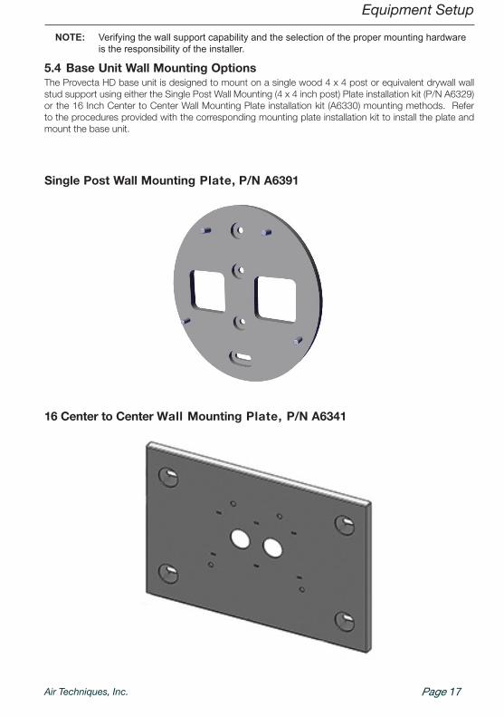
NOTE: Verifying the wall support capability and the selection of the proper mounting hardware is the responsibility of the installer.
5.4 Base Unit Wall Mounting OptionsThe Provecta HD base unit is designed to mount on a single wood 4 x 4 post or equivalent drywall wall stud support using either the Single Post Wall Mounting (4 x 4 inch post) Plate installation kit (P/N A6329) or the 16 Inch Center to Center Wall Mounting Plate installation kit (A6330) mounting methods . Refer to the procedures provided with the corresponding mounting plate installation kit to install the plate and mount the base unit .
Single Post Wall Mounting Plate, P/N A6391
16 Center to Center Wall Mounting Plate, P/N A6341

Air Techniques, Inc.Page 18
Equipment Setup
5.5 Installing the Horizontal ArmMount the horizontal arm on the installed base unit by performing the following procedure .
1 . Insert the horizontal arm shaft into the base unit making sure not to pinch the 3 Wire Harness .
2 . Mount the horizontal arm brake with 2 screws, M5x30 .
3 . Check the horizontal arm using the spirit level and align if necessary .
4 . Connect the three horizontal arm cables A, B and C as shown below .
Top of Base Unit
Horizontal Arm
Horizontal Arm Brake
Horizontal Arm
A
B
C
AB
C
Control Panel Cable

Page 19Air Techniques, Inc.
Equipment Setup
5.6 Installing the Scissor ArmMount the scissor arm onto the installed horizontal arm by performing the following procedure .
NOTE: Apply grease lightly to the scissor arm shaft as necessary.1 . Insert the scissor arm shaft into the horizontal arm making sure not to pinch the attached cables .
2 . Install and tighten the M5x25 grub screw into the hexagon screw .
3 . Make sure the hexagon screw is also tightly screwed in .
4 . Tighten the set screw on the side of the head of the hexagon screw .
1 2
Wire Harness
Scissor Arm Shaft
Horizontal Arm
1 2
Hexagon Screw
Set Screw
Grub Screw
5 . Attach the scissor arm brake with two M5x15 screws with spring washer on the horizontal arm .
6 . Connect the cables of the scissor arm and the horizontal arm and screw on the cover with the two M3x6 flat head screws .
7 . Place the horizontal arm cover on the horizontal arm .
Scissor Arm Brake Cable Connections
Horizontal Arm Cover
CAUTIONScissor arm can spring open causing injury.
• Do not cut strap securing the scissor arm until completion of installation procedures . .
Air Techniques, Inc.Page 20
Equipment Setup
NOTICEDanger of mechanical damage to the X-ray tube• Mechanical damage to the X-ray tube
due to the X-ray emitter falling• Safely mount the X-ray emitter .
CAUTIONDanger of lead poisoning• Do not touch the X-ray tube without
protective clothing .• Wear protective clothes when disas-
sembling the tubular housing .
CAUTIONDamage to the unit due to incomplete assembly• If replacement task is interrupted, the
securing strap can loosen, the unit can fall and the scissor arm can relax .
• Completely mount the X-ray unit .
CAUTIONDamage to the unit due to relaxing of the scissor arm• The scissor arm can relax during
assembly work .• Make sure that the scissor arm is folded
during all assembly work .
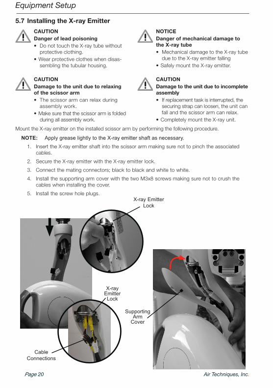
5.7 Installing the X-ray Emitter
Mount the X-ray emitter on the installed scissor arm by performing the following procedure .
NOTE: Apply grease lightly to the X-ray emitter shaft as necessary.1 . Insert the X-ray emitter shaft into the scissor arm making sure not to pinch the associated
cables .
2 . Secure the X-ray emitter with the X-ray emitter lock .
3 . Connect the mating connectors; black to black and white to white .
4 . Install the supporting arm cover with the two M3x8 screws making sure not to crush the cables when installing the cover .
5 . Install the screw hole plugs .X-ray Emitter
Lock
Cable Connections
Supporting Arm
Cover
X-ray Emitter Lock

Page 21Air Techniques, Inc.
Equipment Setup5.8 Connecting the Mains PowerConnection of the mains power supply can be made using the supplied mains cable or direct power connection via fixed facility wiring . Either option is made by performing the same three wire connection . Matching by color, connect the blue and brown wires of the mains power to the corresponding terminal block connections as shown below . Connect the green with yellow stripe wire to the ground terminal .
FixedConnection(optional)
Power Terminal
Block
Mains Cable (supplied)
Power Terminal
Block
5.9 Connecting the Handheld Exposure ButtonConnection of the handheld exposure button to the PCB connector is made by simply inserting the as-sociated wire connector into the mating connector on the bottom of the PCB .
Handheld Exposure Button
RS45 Connector
RS11 Connector
Handheld Exposure Button Connector
Handheld Exposure Button Cable Connection
PowerTerminal Block Connections
Ground Terminal
Green with Yellow Stripe Wire
Brown WireBlue Wire

Air Techniques, Inc.Page 22
Equipment Setup5.10 Assembling the Control UnitAssemble the control unit by performing the following procedure .
1 . Carefully thread the keypad connector cable through the control unit cover and align the cover with the base unit .
2 . Install and tighten the 4 screws (A, B, C,D) securing the control unit cover .
3 . Connect the rear keypad connector of the control panel
4 . Align the panel spine with the control unit cover center groove and slide the control panel down in place .
B
C
A
D
Control Unit Cover
Control Panel
Keypad Connector Cable
Connect

Page 23Air Techniques, Inc.
Equipment Commissioning6 Operation
NOTICEShort circuit due to build up of con-densation• The appliance can only be put into
operation once it has warmed up to room temperature and it is dry .
The necessary tests (e . g . acceptance test) are regulated by the locally applicable national law .• Find out which tests are to be made .• Carry out tests in accordance with national law .
6.1 Acceptance test
When carrying out the commissioning tests where the image plate and sensor are used as receivers, the Intra / Extra Digital test body is required and possi-bly the appropriate test body holder .
• Before commissioning, carry out the acceptance test of the X-ray system according to national reg-ulations .
• The tests of constancy, that must be carried out at regular intervals by the personnel, are based on the results of the acceptance test .
6.2 Electrical safety check• Carry out an electrical safety check according to all national regulations (e .g . patient conductivity,
conductivity of housing) .• Document the results .
6.3 Switch unit onThe display will show the standard values for X-ray exposures or the setting values used for the last exposure carried out .
– Operational display lamps, – LED for menu tooth symbol, – LED for menu Adult/Child and – LED for menu image plate/sensor all light up .

Air Techniques, Inc.Page 24
Equipment Commissioning
6.4 Service menu settings via the control panel
All settings are saved after the first triggering .
• While pressing the button and the button a little longer in order to switch to the Service menu .
Use or browse in the menu .
Use to select the respective menu option .
• In menu option 1 . Cone Type use to scroll and then use to confirm .
Use to go back to the Service menu .
• In menu option 2 . DAP Setting use to scroll and then use to confirm .
Use to go back to the Service menu .
• In menu option 3 . Default Value Reset, press to confirm .
• In menu option 4 . kV Option use to scroll and then use to confirm, 50-70 kV are permissible in countries with no X-ray limit regulations .
• In menu option 5 . X-ray Count use to scroll and then use to confirm .
• In the menu option 6 . Expo S/W Set use to make the respective selection and use to confirm .
• Under menu option 6 . Version the current firmware version can be called up . Use to acknowledge .
• Under menu option 7 . Demo the demo version can be started by pressing the button .
• After entering all required values, press the button to exit the Service menu .
2
4
3
7 56
1
8
9
1 LED Display 4 Adult/Child selector 7 Stand-by/Power indicator
2 Anatomical selector 5 X-ray emission indicator 8 Save key
3 Parameter adjustment key 6 Exposure button 9 Image plate/sensor selector

Page 25Air Techniques, Inc.
Online Warranty RegistrationQuickly and easily register your new Provecta HD online . Just have your product model and serial numbers available . Then go to the Air Techniques web site, www.airtechniques.com, click the Warranty Registration link at the top of the page and complete the registration form . This online registration ensures a record for the warranty period and helps us keep you informed of product updates and other valuable information .
Provecta HD is warranted to be free from defects in material and workmanship from the date of installation for a period of 2 years (24 months) . Provecta HD is designed solely for use in a dental office environment and this warranty is not applicable to other applications .
All part and component returns and replacement of equipment under warranty require a Return Materials Authorization (RMA) . Items returned without an RMA, or included with other products for which an RMA has been issued, may be returned to the customer at the discretion of Air Techniques .
Any item returned under warranty, will be repaired or replaced at our option at no charge provided that our inspection shall indicate it to have been defective . Air Techniques, Inc . is not liable for indirect or consequential damages or loss of any nature in connection with this equipment . Dealer labor, shipping and handling charges are not covered by this warranty .
Warranty credit will not be applied to product returns that exhibit damage due to shipping, mis-use, careless handling or repairs by unauthorized service personnel . Credit, or partial credit, will not be issued until product/parts have been received and assessed . Warranty is void if product is installed or serviced by anyone other than authorized Air Techniques dealer service personnel . This warranty is void if Provecta HD is operated with any covers removed .
This warranty is in lieu of all other warranties expressed or implied . No representative or person is authorized to assume for us any liability in connection with the sale of our equipment .
Warranty

© Air Techniques, Inc Copyright 2014 • P/N A6385, Rev. 10 • November 2015
Digital Imaging• Digital Radiography• Intraoral Camera• Caries Detection Aid• Intraoral X-ray• Panoramic X-ray• Film Processors
Utility Room • Dry Vacuums• Wet Vacuums• Air Compressors• Amalgam Separator• Utility Accessories• Utility Packages
Corporate Headquarters1295 Walt Whitman Road | Melville, New York 11747- 3062
Phone: 1-800-247-8324 | Fax: 1-888-247-8481
Western Facility291 Bonnie Lane, Suite 101 | Corona, CA 92880 - 2804
Phone: 1-800-247-8324 | Fax: 1-951-898-7646
www.air techniques.com
Scan QR Code for more about Provecta HD
Merchandise• Surface Disinfectant• Enzymatic Cleaner• Hand Sanitizer and Lotion• Waterline Cleaner• Evacuation System Cleaner• Imaging Accessories• Chemistry• Processor Accessories
For over 50 years, Air Techniques has been a leading innovator and manufac-turer of dental products. Our priority is ensuring complete satisfaction by man-ufacturing reliable products and providing excellent customer and technical support. Whether the need is digital imaging, utility room equipment or mer-chandise, Air Techniques can provide the solution via our network of authorized professional dealers. Our products are helping dental professionals take their practices to the next level.
Air Techniques’ family of quality products for the dental professional include: