interstage 2-3 of vega c launcher: composite grid
TRANSCRIPT
ECCM18 - 18th European Conference on Composite Materials
Athens, Greece, 24-28th June 2018 1
G. Giusto, P. Spena, G. Totaro, F. De Nicola, F. Di Caprio, A. Zallo, M. Cioeta and S. Mespoulet
INTERSTAGE 2-3 OF VEGA C LAUNCHER:
COMPOSITE GRID STRUCTURE TECHNOLOGY
G. Giusto 1, P. Spena 1, G. Totaro 1, F. De Nicola 1, F. Di Caprio 1, A. Zallo 2, M. Cioeta 2 and S.
Mespoulet 3
1 CIRA Italian Aerospace Research Centre, Via Maiorise 81043 Capua (CE), Italy
Email: [email protected], Web Page: https://www.cira.it/it 2 Avio s.p.a, Via Ariana Km 5.2 - 00034 Colleferro (Rome), Italy
Email: [email protected], Web Page: http://www.avio.com 3 ESA European Space Agency, Largo Galileo Galilei 1 – CP 64 - 00044 Frascati (Rome), Italy
Email: [email protected], Web Page: https://www.esa.int/ESA
Keywords: Interstage, Grid Structure, Composite, Filament Winding
Abstract
The Interstage 2/3 is the structure that interfaces the Z40 second stage with the Z9 third stage of the new
VEGA-C launch vehicle. The design concept developed for this structure is a “composite GRID
architecture” which consists in a regular and rather dense system of interlaced hoop and helical
unidirectional ribs completed with a thin outer skin with a secondary structural role.
Interlaced ribs determine a fiber volumetric fraction that, except for the nodal regions, is usually lower
than standard applications in composite material. Despite this, the typical mechanical properties are
sufficient to design highly efficient solutions for heavily-loaded structures.
The developed manufacturing process is based on the automated parallel winding of dry carbon fiber
tows followed by liquid resin infusion under vacuum bag. The combination of a suitable design method
and manufacturing process turns out to be very appealing to produce lightweight and low cost composite
grid structures for space applications.
This paper shows the general aspects inherent to the technology development and the design definition
of the new VEGA C Interstage 2-3.
1. INTRODUCTION
The Grid technology in composite material based on Filament Winding is probably the most efficient
design and manufacturing solution to address heavily-loaded axisymmetric shell structures [1-2]. Other
automated deposition techniques based on Fiber Placement are being developed, as per [3].
In the last years, CIRA has developed methods to optimize the Grid technology by winding in terms
of design and manufacturing with the aim to: identify the proper structural configuration, enhance the
mechanical properties and the overall quality of the process, reduce the cost. This know-how has been
successfully applied for the structural model of the Vega I/S 2-3 in the framework of a project funded
by the Italian Space Agency [4]. Starting from this background, CIRA and Avio have proposed the
GRID concept for the “Development and qualification of the Interstage 2/3 of the VEGA C launcher”
winning the dedicated ITT of the European Space Agency.
2. I/S 2-3 PRELIMINARY DESIGN APPROACH
The I/S 2-3 is a conical shell structure that must fulfil the following main functions:
- To transmit the thrust from the second stage SRM to the launcher third stage;
ECCM18 - 18th European Conference on Composite Materials
Athens, Greece, 24-28th June 2018 2
G. Giusto, P. Spena, G. Totaro, F. De Nicola, F. Di Caprio, A. Zallo, M. Cioeta and S. Mespoulet
- To provide a certain overall stiffness;
- To house and protect equipment and components;
- To guarantee the separation of the second stage
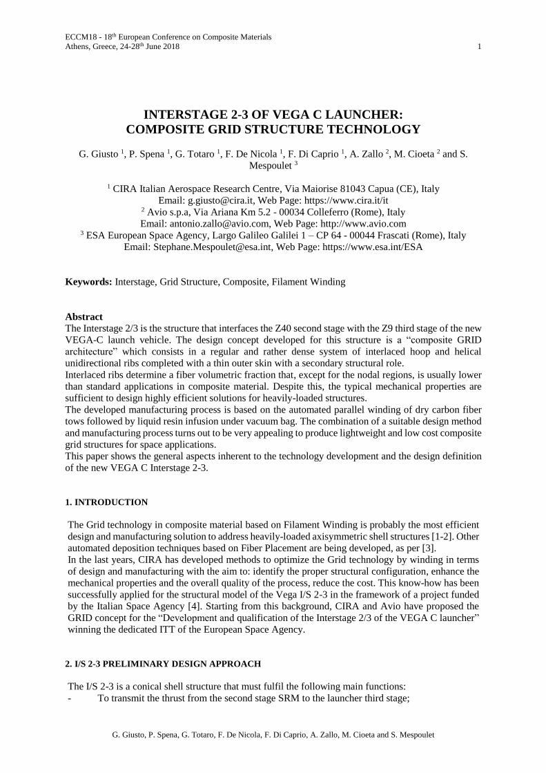
The conical grid structure has been designed in order to guarantee this overall capability with minimum
mass and cost. In principle, this design concept appears quite peculiar in view of the mass minimization
and the general design constraints (strength, buckling, stiffness). Indeed, there are several
configurations for a grid structure that are identified by the number of hoop and helical ribs, and by
three continuous variables H, bc, bh that represent the radial thickness and the width of hoop and helical
ribs, respectively (Figure 1). The spacings between hoop and helical ribs are denoted with ac and ah, in
the same figure. The angle between the helical rib and the local meridian of the shell is the
fundamental design variable. We remark that, in contrast to cylindrical grid structures, since the path
of helical ribs needs to be coincident, in any case, with the geodesic trajectories of the shell (in order
to provide a stable trajectory during the continuous deposition of fibers by filament winding) the helical
angle and the spacing are not constant along the meridian of the cone. In particular, in correspondence
to the large radius of the shell (lower section), the helical angle is minimum and vice versa in
correspondence to the small radius of the shell (upper section).
The identification of the minimum mass configuration in terms of the number of hoop and helical ribs
and corresponding cross-sections has been undertaken with the aid of an optimization procedure similar
to the approach proposed in [5]. The objective function of this procedure is given by the mass of the
conical grid structure (without the skin) with design constraints that are analytically formulated based
on the intact structure (i.e., no interfaces or any kind of discontinuity). These constraints correspond to
the main failure mechanisms that can be experienced by the structure under the action of
compressive/bending loads, namely, global buckling modes of the shell, lateral buckling modes of ribs,
and material failure of helical ribs. Further design constraints involve the axial and the bending global
stiffness requirements of the shell that have been analytically addressed according to the recently
formulated models [6].
Figure 1. Typical design parameters of a grid structure.
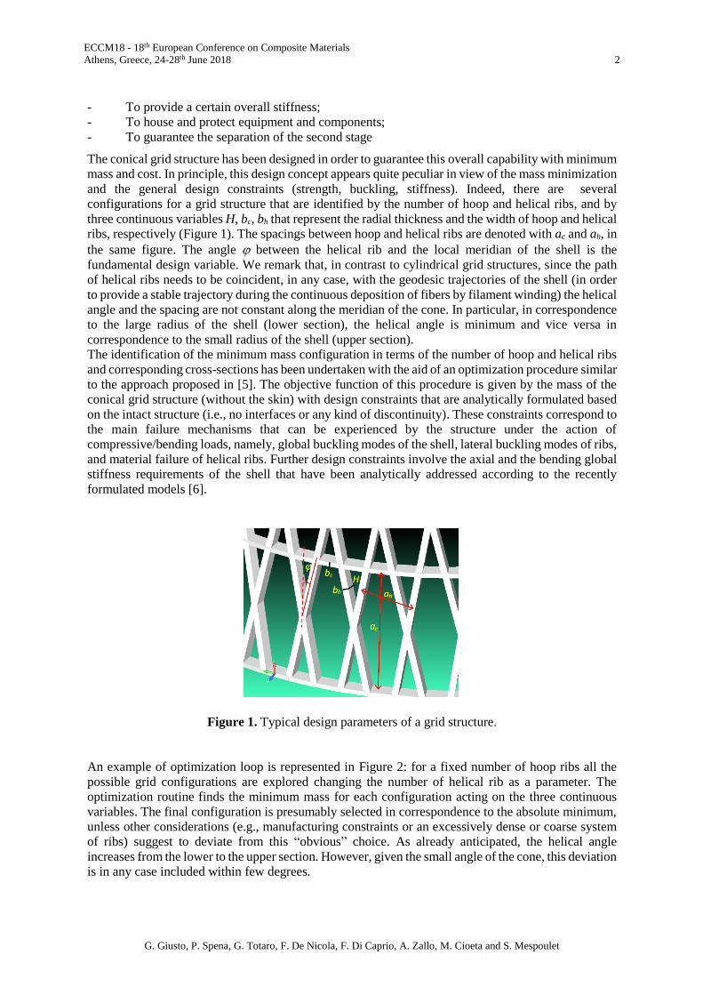
An example of optimization loop is represented in Figure 2: for a fixed number of hoop ribs all the
possible grid configurations are explored changing the number of helical rib as a parameter. The
optimization routine finds the minimum mass for each configuration acting on the three continuous
variables. The final configuration is presumably selected in correspondence to the absolute minimum,
unless other considerations (e.g., manufacturing constraints or an excessively dense or coarse system
of ribs) suggest to deviate from this “obvious” choice. As already anticipated, the helical angle
increases from the lower to the upper section. However, given the small angle of the cone, this deviation
is in any case included within few degrees.
ECCM18 - 18th European Conference on Composite Materials
Athens, Greece, 24-28th June 2018 3
G. Giusto, P. Spena, G. Totaro, F. De Nicola, F. Di Caprio, A. Zallo, M. Cioeta and S. Mespoulet
Figure 2. Example of an optimization loop (left), helical angles at the edges (right)
After the identification of the optimal grid configuration, several minor design loops were conducted
with the aid of additional routines. The objective of these loops was to facilitate the concurrent design
and integration of the aluminium flanges (connection and separation flanges) according to the specific
pattern of the grid structure. This was done verifying the effect of small modifications of the basic
geometry of the conical shell (the small and large radius, the height and even the angle of the cons) in
the range of few millimetres or few tenths of degree. After each modification of the geometry a
successive step with CAD tools was necessary in order to construct the fully 3D model of the grid
structure and check the proper integration with the flanges. Then, all the necessary steps to complete
the design were undertaken.
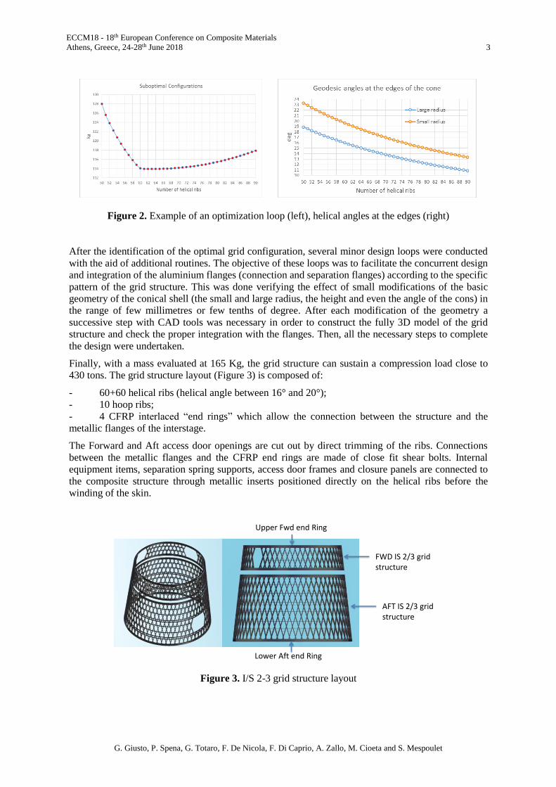
Finally, with a mass evaluated at 165 Kg, the grid structure can sustain a compression load close to
430 tons. The grid structure layout (Figure 3) is composed of:
- 60+60 helical ribs (helical angle between 16° and 20°);
- 10 hoop ribs;
- 4 CFRP interlaced “end rings” which allow the connection between the structure and the
metallic flanges of the interstage.
The Forward and Aft access door openings are cut out by direct trimming of the ribs. Connections
between the metallic flanges and the CFRP end rings are made of close fit shear bolts. Internal
equipment items, separation spring supports, access door frames and closure panels are connected to
the composite structure through metallic inserts positioned directly on the helical ribs before the
winding of the skin.
Figure 3. I/S 2-3 grid structure layout
FWD IS 2/3 grid structure
AFT IS 2/3 grid structure
Lower Aft end Ring
Upper Fwd end Ring

ECCM18 - 18th European Conference on Composite Materials
Athens, Greece, 24-28th June 2018 4
G. Giusto, P. Spena, G. Totaro, F. De Nicola, F. Di Caprio, A. Zallo, M. Cioeta and S. Mespoulet
3. MANUFACTURING APPROACH
The manufacturing process is based on the robotic/filament winding of dry tows in a rubber carpet with
grooves corresponding to the grid architecture to be realized. Then the process is completed with resin
infusion under vacuum bag. The dry winding process with respect to the wet winding eliminates the
exposure to solvents and volatiles of the resin, avoids pot life problems, and limits the entrapping of
air bubbles. At the same time, the fiber volumetric fraction and the basic mechanical properties are
very similar to the wet winding process.
The main phases of the manufacturing process of the Interstage 2-3 are:
Preparation and assembly of rubber carpet on the mandrel
Winding of the grid structure (including end rings)
Winding of the outer skin
Resin infusion at RT under vacuum bag and cure in autoclave
The rubber carpet is realized by casting in a metallic mould and reproduces the geometrical parameters
and trajectories of hoop and helical ribs. The rubber tool, with its thermal expansion during the cure
cycle, appears useful to consolidate the ribs and to locally increase the fiber volumetric fraction,
squeezing out voids and compacting the rib-skin interface. The use of rubber carpet is similar to the
original American or Russian process, but an improvement has been conceived, that is, the adoption of
a double carpet made of a massive (and reusable) part, and a light part that gives the surface finishing
to the ribs. This is useful to facilitate the extraction of the carpet itself in case of grid structures with
skin.
Regarding the winding of the grid structure, the deposition strategy is patented [7] and is based on a
“parallel winding” of hoop and helical ribs. This means that the system of interlaced hoop and helical
ribs is layered down in the grooves by means of a parallel scheme, as represented in Figure 4. A
multiple spool, with a number of separate eyes equal to the number of hoop ribs, all fixed in the right
positions along the axis of rotation, supplies fibers to the rotating mandrel, while an extra eye moves
along the mandrel to wind helical ribs. This logic scheme allows us to have a really continuous process,
providing a complete interlaced dry preform, without the necessity to cut tows for each layer in the
hoop ribs, nor to introduce dummy helical ribs in order to pass from a hoop to another one.
Figure 4. Patented technique to interlace the grid structure ribs (helixes) and hoop
Also the CFRP end rings are interlaced with the helical ribs, and ensure the integration of continuous
reinforcing “black rings” made of biaxial fabric, in order to allow the connection between the CFRP
grid structure and the metallic flanges of the interstage.
Once the grid structure is complete, the metallic insert are positioned and the outer skin is wound with
the same dry tows that are used for the ribs. It is particularly thin and has a secondary structural role.
At the end of the winding, the overall dry preform (made of grid with the interlaced end rings and
external skin) is co-infused at room temperature and co-cured in autoclave.
ECCM18 - 18th European Conference on Composite Materials
Athens, Greece, 24-28th June 2018 5
G. Giusto, P. Spena, G. Totaro, F. De Nicola, F. Di Caprio, A. Zallo, M. Cioeta and S. Mespoulet
4. MATERIAL TRADE-OFF
Most of the initial activities were aimed at the proper selection of all the materials needed, considering
the nature of the manufacturing process to be implemented for the interstage, and starting from the
preliminary design of the grid structure. The materials to be selected were:
- Carbon tow for the ribs,
- Carbon tape for the end rings,
- Resin for the composite matrix.
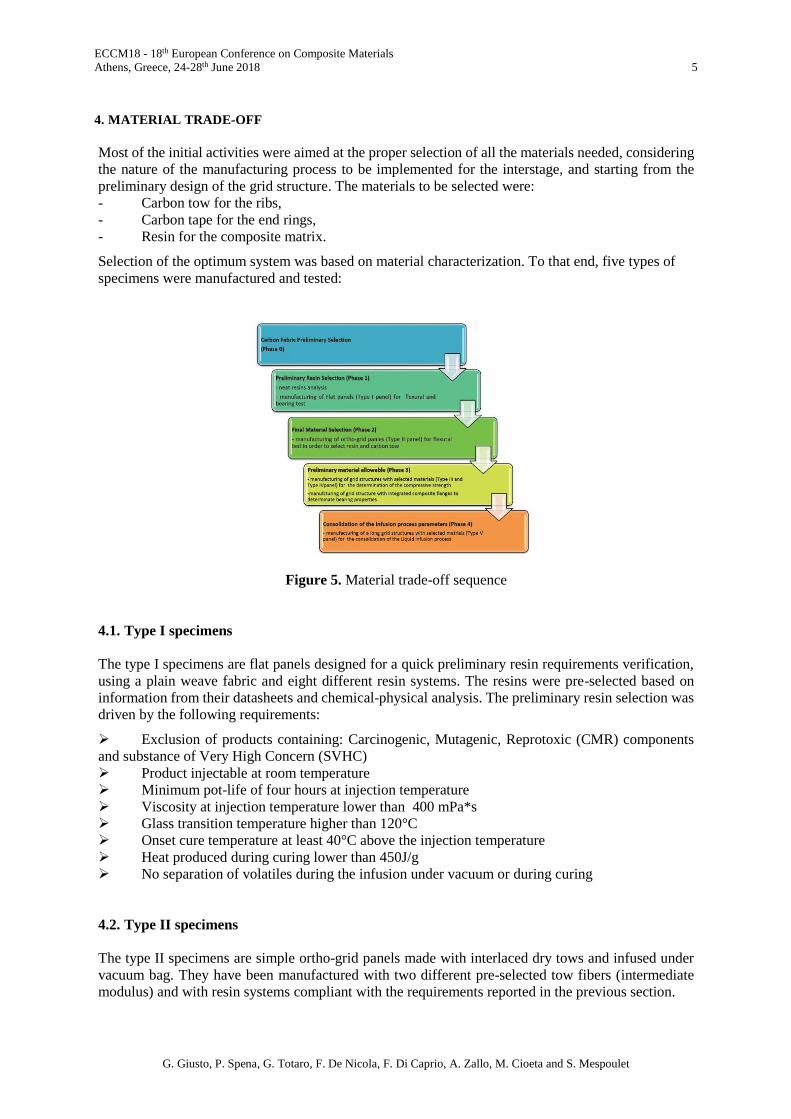
Selection of the optimum system was based on material characterization. To that end, five types of
specimens were manufactured and tested:
Figure 5. Material trade-off sequence
4.1. Type I specimens
The type I specimens are flat panels designed for a quick preliminary resin requirements verification,
using a plain weave fabric and eight different resin systems. The resins were pre-selected based on
information from their datasheets and chemical-physical analysis. The preliminary resin selection was
driven by the following requirements:
Exclusion of products containing: Carcinogenic, Mutagenic, Reprotoxic (CMR) components
and substance of Very High Concern (SVHC)
Product injectable at room temperature
Minimum pot-life of four hours at injection temperature
Viscosity at injection temperature lower than 400 mPa*s
Glass transition temperature higher than 120°C
Onset cure temperature at least 40°C above the injection temperature
Heat produced during curing lower than 450J/g
No separation of volatiles during the infusion under vacuum or during curing
4.2. Type II specimens
The type II specimens are simple ortho-grid panels made with interlaced dry tows and infused under
vacuum bag. They have been manufactured with two different pre-selected tow fibers (intermediate
modulus) and with resin systems compliant with the requirements reported in the previous section.
ECCM18 - 18th European Conference on Composite Materials
Athens, Greece, 24-28th June 2018 6
G. Giusto, P. Spena, G. Totaro, F. De Nicola, F. Di Caprio, A. Zallo, M. Cioeta and S. Mespoulet
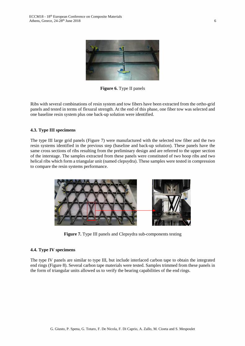
Figure 6. Type II panels
Ribs with several combinations of resin system and tow fibers have been extracted from the ortho-grid
panels and tested in terms of flexural strength. At the end of this phase, one fiber tow was selected and
one baseline resin system plus one back-up solution were identified.
4.3. Type III specimens
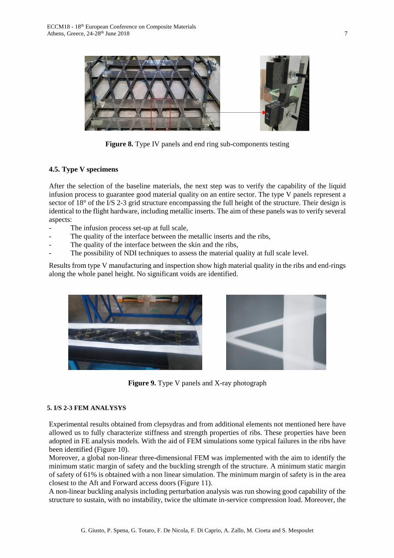
The type III large grid panels (Figure 7) were manufactured with the selected tow fiber and the two
resin systems identified in the previous step (baseline and back-up solution). These panels have the
same cross sections of ribs resulting from the preliminary design and are referred to the upper section
of the interstage. The samples extracted from these panels were constituted of two hoop ribs and two
helical ribs which form a triangular unit (named clepsydra). These samples were tested in compression
to compare the resin systems performance.
Figure 7. Type III panels and Clepsydra sub-components testing
4.4. Type IV specimens
The type IV panels are similar to type III, but include interlaced carbon tape to obtain the integrated
end rings (Figure 8). Several carbon tape materials were tested. Samples trimmed from these panels in
the form of triangular units allowed us to verify the bearing capabilities of the end rings.
ECCM18 - 18th European Conference on Composite Materials
Athens, Greece, 24-28th June 2018 7
G. Giusto, P. Spena, G. Totaro, F. De Nicola, F. Di Caprio, A. Zallo, M. Cioeta and S. Mespoulet
Figure 8. Type IV panels and end ring sub-components testing
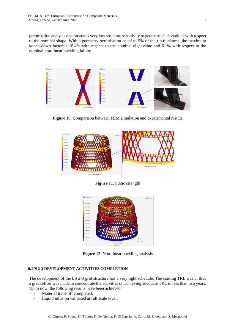
4.5. Type V specimens
After the selection of the baseline materials, the next step was to verify the capability of the liquid
infusion process to guarantee good material quality on an entire sector. The type V panels represent a
sector of 18° of the I/S 2-3 grid structure encompassing the full height of the structure. Their design is
identical to the flight hardware, including metallic inserts. The aim of these panels was to verify several
aspects:
- The infusion process set-up at full scale,
- The quality of the interface between the metallic inserts and the ribs,
- The quality of the interface between the skin and the ribs,
- The possibility of NDI techniques to assess the material quality at full scale level.
Results from type V manufacturing and inspection show high material quality in the ribs and end-rings
along the whole panel height. No significant voids are identified.
Figure 9. Type V panels and X-ray photograph
5. I/S 2-3 FEM ANALYSYS
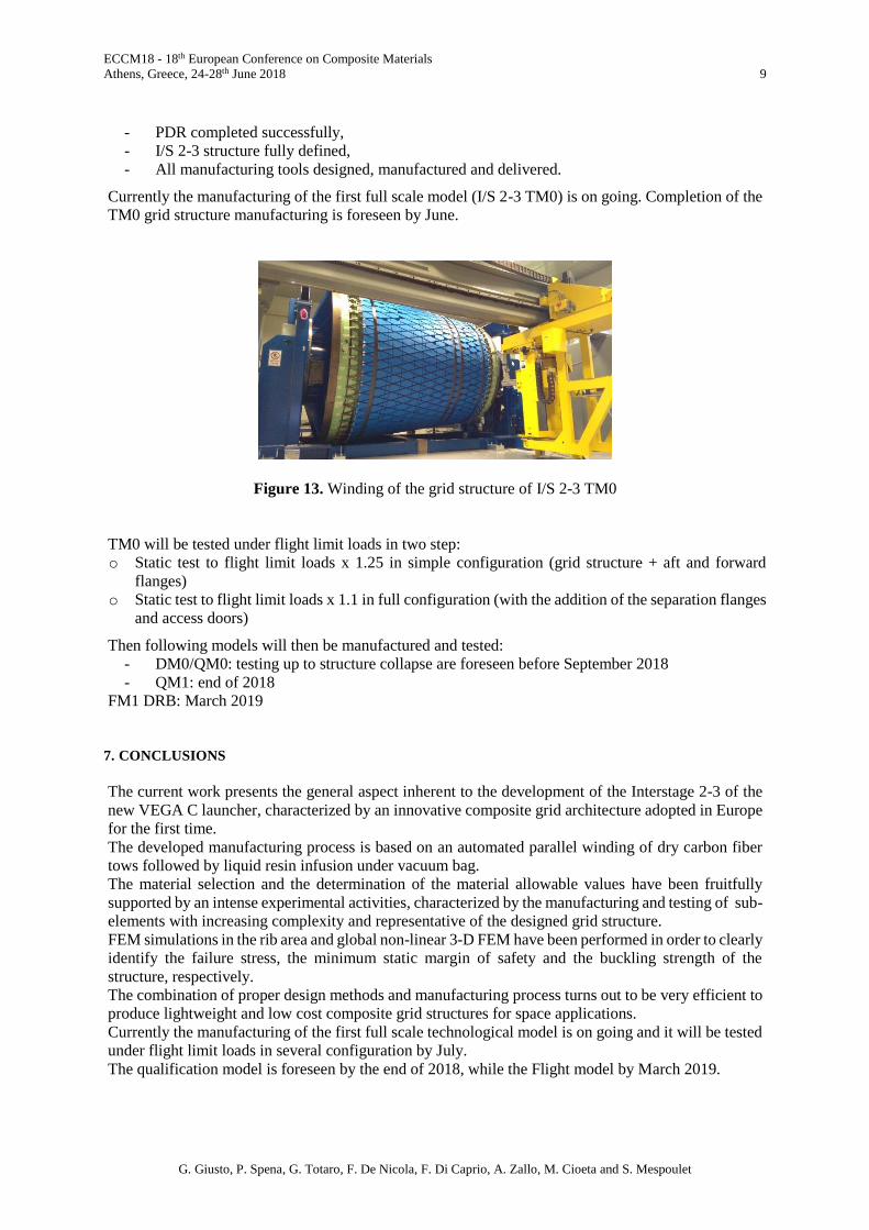
Experimental results obtained from clepsydras and from additional elements not mentioned here have
allowed us to fully characterize stiffness and strength properties of ribs. These properties have been
adopted in FE analysis models. With the aid of FEM simulations some typical failures in the ribs have
been identified (Figure 10).
Moreover, a global non-linear three-dimensional FEM was implemented with the aim to identify the
minimum static margin of safety and the buckling strength of the structure. A minimum static margin
of safety of 61% is obtained with a non linear simulation. The minimum margin of safety is in the area
closest to the Aft and Forward access doors (Figure 11).
A non-linear buckling analysis including perturbation analysis was run showing good capability of the
structure to sustain, with no instability, twice the ultimate in-service compression load. Moreover, the
ECCM18 - 18th European Conference on Composite Materials
Athens, Greece, 24-28th June 2018 8
G. Giusto, P. Spena, G. Totaro, F. De Nicola, F. Di Caprio, A. Zallo, M. Cioeta and S. Mespoulet
perturbation analysis demonstrates very low structure sensitivity to geometrical deviations with respect
to the nominal shape. With a geometry perturbation equal to 5% of the rib thickness, the maximum
knock-down factor is 16.4% with respect to the nominal eigenvalue and 6.1% with respect to the
nominal non-linear buckling failure.
Figure 10. Comparison between FEM simulation and experimental results
Figure 11. Static strength
Figure 12. Non-linear buckling analysis
6. I/S 2-3 DEVELOPMENT ACTIVITIES COMPLETION
The development of the I/S 2-3 grid structure has a very tight schedule. The starting TRL was 5, thus
a great effort was made to concentrate the activities on achieving adequate TRL in less than two years.
Up to now, the following results have been achieved:
- Material trade off completed,
- Liquid infusion validated at full scale level,
ECCM18 - 18th European Conference on Composite Materials
Athens, Greece, 24-28th June 2018 9
G. Giusto, P. Spena, G. Totaro, F. De Nicola, F. Di Caprio, A. Zallo, M. Cioeta and S. Mespoulet
- PDR completed successfully,
- I/S 2-3 structure fully defined,
- All manufacturing tools designed, manufactured and delivered.
Currently the manufacturing of the first full scale model (I/S 2-3 TM0) is on going. Completion of the
TM0 grid structure manufacturing is foreseen by June.
Figure 13. Winding of the grid structure of I/S 2-3 TM0
TM0 will be tested under flight limit loads in two step:
o Static test to flight limit loads x 1.25 in simple configuration (grid structure + aft and forward
flanges)
o Static test to flight limit loads x 1.1 in full configuration (with the addition of the separation flanges
and access doors)
Then following models will then be manufactured and tested:
- DM0/QM0: testing up to structure collapse are foreseen before September 2018
- QM1: end of 2018
FM1 DRB: March 2019
7. CONCLUSIONS
The current work presents the general aspect inherent to the development of the Interstage 2-3 of the
new VEGA C launcher, characterized by an innovative composite grid architecture adopted in Europe
for the first time.
The developed manufacturing process is based on an automated parallel winding of dry carbon fiber
tows followed by liquid resin infusion under vacuum bag.
The material selection and the determination of the material allowable values have been fruitfully
supported by an intense experimental activities, characterized by the manufacturing and testing of sub-
elements with increasing complexity and representative of the designed grid structure.
FEM simulations in the rib area and global non-linear 3-D FEM have been performed in order to clearly
identify the failure stress, the minimum static margin of safety and the buckling strength of the
structure, respectively.
The combination of proper design methods and manufacturing process turns out to be very efficient to
produce lightweight and low cost composite grid structures for space applications.
Currently the manufacturing of the first full scale technological model is on going and it will be tested
under flight limit loads in several configuration by July.
The qualification model is foreseen by the end of 2018, while the Flight model by March 2019.
ECCM18 - 18th European Conference on Composite Materials
Athens, Greece, 24-28th June 2018 10
G. Giusto, P. Spena, G. Totaro, F. De Nicola, F. Di Caprio, A. Zallo, M. Cioeta and S. Mespoulet
References
[1] V.V. Vasiliev and A.F. Razin. Anisogrid composite lattice structures for spacecraft and aircraft
applications. Composite Structures, 76:182-189, 2006.
[2] V.V. Vasiliev, V.A. Barynin, and A.F. Razin. Anisogrid composite lattice structures-Development
and aerospace applications. Composite Structures, 94:1117-1127, 2012.
[3] C. B. Mangas, J. Vilanova, V. Diaz, C. R. Samartin et al. Anisogrid payload adaptor structure for
Vega launcher. Proceedings of the 14th European Conference on Spacecraft Structures, Materials
and Environmental Testing (ECSSMET), Toulouse, France, September 2106.
[4] G. Totaro and F. De Nicola. Recent advance on design and manufacturing of composite anisogrid
structures for space launchers. Acta Astronautica, 81:570-577, 2102.
[5] G. Totaro and Z. Gürdal. Optimal design of composite shell structures for aerospace applications.
Aerospace Science and Technology, 13:157-164, 2009.
[6] G. Totaro. Flexural, torsional, and axial global stiffness properties of anisogrid lattice conical shells
in composite materials. Composite Structures, 153:738-745, 2016.
[7] F. De Nicola, G. Totaro, and C. Vitiello. Sistema per la Deposizione di materiali compositi in Wet
Winding con rotazione infinita dell’occhio e con distribuzione parallela di supporto. Patent
IT0001397218.