internet enabled system control and monitoringvickysagarwal.tripod.com/projects/iescm.pdf ·...
TRANSCRIPT
INTERNET ENABLED SYSTEM CONTROL AND MONITORING
STUDY PHASE REPORT
BY
Vikas Agarwal
UNDER THE GUIDANCE OF
Dr. L. Umanand
T. V. Prabhakar
N. V. C. Rao
CENTRE FOR ELECTRONICS DESIGN AND TECHNOLOGY
INDIAN INSTITUTE OF SCIENCE BANGALORE - 560012.
November 2003

Indian Institute of Science CEDT
Internet Enabled System Control and Monitoring
11/25/2003 2 of 18
INDEX
1. NEED ANALYSIS ...........................................................................................................3
2. MOTIVATION.................................................................................................................4 3. PRODUCT CONCEPTUALIZATION..............................................................................5
4. PRODUCT DETAILS.......................................................................................................6 COMPONENT MODULES OF THE PRODUCT..........................................................................6 4.1 CLIENT PC.................................................................................................................6 4.2 WEB SERVER .............................................................................................................6 GUI….............................................................................................................................7 4.3 INTERFACE UNIT ........................................................................................................7 4.4 USB-JTAG INTERFACE DEVELOPMENT......................................................................8 4.4.1 USB CONTROLLER:.................................................................................................9 4.4.2 JTAG CONTROLLER:............................................................................................. 10 4.5 DSP CONTROL......................................................................................................... 10
5. SPECIFICATION REVIEW MINUTES......................................................................... 12 6. SCOPE OF WORK......................................................................................................... 13
7. TARGET SPECIFICATIONS......................................................................................... 14 8. TIME PLAN ................................................................................................................... 18
Indian Institute of Science CEDT
Internet Enabled System Control and Monitoring
11/25/2003 3 of 18
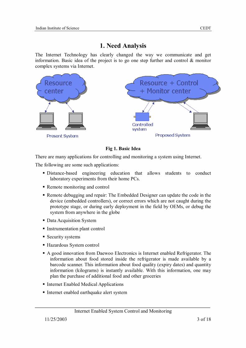
1. Need Analysis The Internet Technology has clearly changed the way we communicate and get information. Basic idea of the project is to go one step further and control & monitor complex systems via Internet.
Fig 1. Basic Idea There are many applications for controlling and monitoring a system using Internet. The following are some such applications:
Distance-based engineering education that allows students to conduct laboratory experiments from their home PCs.
Remote monitoring and control Remote debugging and repair: The Embedded Designer can update the code in the
device (embedded controllers), or correct errors which are not caught during the prototype stage, or during early deployment in the field by OEMs, or debug the system from anywhere in the globe
Data Acquisition System
Instrumentation plant control
Security systems
Hazardous System control A good innovation from Daewoo Electronics is Internet enabled Refrigerator. The
information about food stored inside the refrigerator is made available by a barcode scanner. This information about food quality (expiry dates) and quantity information (kilograms) is instantly available. With this information, one may plan the purchase of additional food and other groceries
Internet Enabled Medical Applications
Internet enabled earthquake alert system
Indian Institute of Science CEDT
Internet Enabled System Control and Monitoring
11/25/2003 4 of 18
2. Motivation
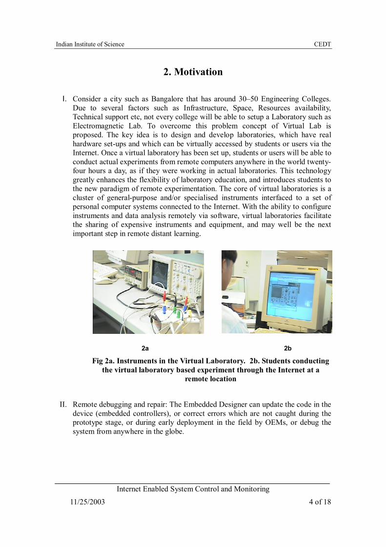
I. Consider a city such as Bangalore that has around 30–50 Engineering Colleges. Due to several factors such as Infrastructure, Space, Resources availability, Technical support etc, not every college will be able to setup a Laboratory such as Electromagnetic Lab. To overcome this problem concept of Virtual Lab is proposed. The key idea is to design and develop laboratories, which have real hardware set-ups and which can be virtually accessed by students or users via the Internet. Once a virtual laboratory has been set up, students or users will be able to conduct actual experiments from remote computers anywhere in the world twenty-four hours a day, as if they were working in actual laboratories. This technology greatly enhances the flexibility of laboratory education, and introduces students to the new paradigm of remote experimentation. The core of virtual laboratories is a cluster of general-purpose and/or specialised instruments interfaced to a set of personal computer systems connected to the Internet. With the ability to configure instruments and data analysis remotely via software, virtual laboratories facilitate the sharing of expensive instruments and equipment, and may well be the next important step in remote distant learning.
2a 2b
Fig 2a. Instruments in the Virtual Laboratory. 2b. Students conducting the virtual laboratory based experiment through the Internet at a
remote location
II. Remote debugging and repair: The Embedded Designer can update the code in the device (embedded controllers), or correct errors which are not caught during the prototype stage, or during early deployment in the field by OEMs, or debug the system from anywhere in the globe.
Indian Institute of Science CEDT
Internet Enabled System Control and Monitoring
11/25/2003 5 of 18
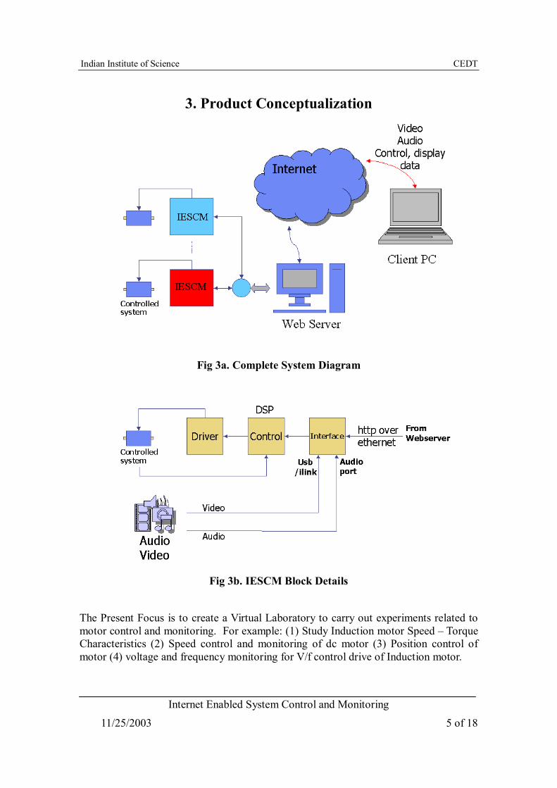
3. Product Conceptualization
Fig 3a. Complete System Diagram
Fig 3b. IESCM Block Details
The Present Focus is to create a Virtual Laboratory to carry out experiments related to motor control and monitoring. For example: (1) Study Induction motor Speed – Torque Characteristics (2) Speed control and monitoring of dc motor (3) Position control of motor (4) voltage and frequency monitoring for V/f control drive of Induction motor.
Indian Institute of Science CEDT
Internet Enabled System Control and Monitoring
11/25/2003 6 of 18
4. Product Details Component modules of the Product
Client PC
Web Server Interface Unit - Motherboard
USB – JTAG interface Development DSP Board
4.1 Client PC Internet Connection
Web Browser Multimedia Kit Pentium III or Higher
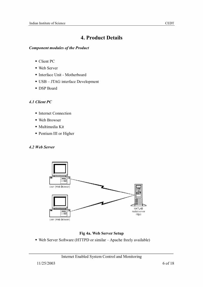
4.2 Web Server
Fig 4a. Web Server Setup Web Server Software (HTTPD or similar – Apache freely available)
Indian Institute of Science CEDT
Internet Enabled System Control and Monitoring
11/25/2003 7 of 18
Matlab Web Server Audio-Video Streaming
Ethernet Interface to Motherboard Design a Virtual Experiment
Designing GUI - HTML forms for Control Inputs required for experiment and displaying results.
Establishing a connection between Client PC and Web Server, Test for Audio/Video and data transfer.
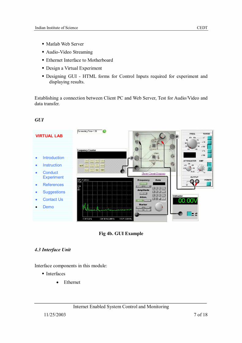
GUI
Fig 4b. GUI Example
4.3 Interface Unit
Interface components in this module: Interfaces
• Ethernet
VIRTUAL LAB
• Introduction
• Instruction
• Conduct Experiment
• References
• Suggestions
• Contact Us
• Demo
Indian Institute of Science CEDT
Internet Enabled System Control and Monitoring
11/25/2003 8 of 18
• USB
• Audio Port
• Video Port
• Serial Port
• JTAG Interface to DSP
• IEEE1394/Fierwire/iLink port
• Wi-Fi Interface Controlling data movements
Ethernet Interface to Web Server Interface Software
Audio/Video Compression Techniques Board Design
PCB – EMI issues Populate PCB
Testing Board As all of the above interfaces except the JTAG interface to DSP are available on general PC motherboards, the task of would reduce to selection of the proper motherboard.
4.4 USB-JTAG Interface Development
An USB-JTAG Emulator provides a link between DSP Processor and Interface board. It is required for Programming and Debugging the DSP processor. Tasks to be done:
Exhaustive Study of USB Protocol Exhaustive Study of JTAG Protocol
Decision about implementing JTAG in FPGA or master TAP controllers
USB Controller selection from various vendors
JTAG TAP Controller selection Interface Design
Development of USB Device Drivers Interfacing Application (CCS – IDE) to USB Device driver
USB Firmware development
Indian Institute of Science CEDT
Internet Enabled System Control and Monitoring
11/25/2003 9 of 18
USB controller – TAP controller Interface design Interface Software design
PCB Testing
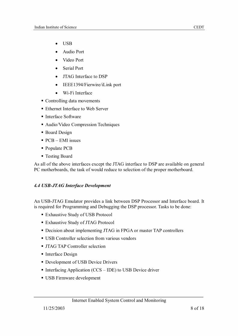
Fig 4c. Block Diagram of USB-JTAG Controller
4.4.1 USB Controller: Texas Instruments TUSB3210 USB Controller is selected because of following features:
Multiproduct support with one code and one chip (up to 16 products with one chip)
Fully compliant with the USB release 2.0 full-speed specification
Supports 12 Mbits/s USB data rate (full speed)
Motherboard
USB Connector
USB Controller
TUSB3210
14 pin JTAG Connector
JTAG Controller
SN748990
RAM EEPROM
USB cable
USB Port
DSP Control Board
14 pin JTAG Connector
TMS320LF2407

Indian Institute of Science CEDT
Internet Enabled System Control and Monitoring
11/25/2003 10 of 18
Supports USB suspend/resume and remote wake-up operation Integrated 8052 microcontroller with:
• 256 × 8 RAM for internal data
• 8K × 8 RAM code space available for downloadable firmware from host or I2C port.
• 512 × 8 shared RAM used for data buffers and endpoint descriptor blocks (EDB)
• Four 8052 GPIO ports, ports 0,1, 2, and 3
• Master I2C controller for external slave device access Operates from a 12-MHz crystal
On-chip PLL generates 48 MHz Supports a total of 3 input and 3 output (interrupt, bulk) endpoints
Power-down mode
4.4.2 JTAG Controller: SN74ACT8990 - IEEE STD 1149.1 (JTAG) TAP MASTERS WITH 16-BIT GENERIC HOST INTERFACES Members of the Texas Instruments SCOPE Family of Testability Products
Compatible With the IEEE Standard 1149.1-1990 (JTAG) Test Access Port and Boundary-Scan Architecture
Control Operation of Up to Six Parallel Target Scan Paths Accommodate Pipeline Delay to Target of Up to 31 Clock Cycles
Scan Data Up to 232 Clock Cycles Execute Instructions for Up to 232 Clock Cycles
Each Device Includes Four Bidirectional Event Pins for Additional Test Capability Inputs Are TTL-Voltage Compatible
16 – Bit Generic Host Interface
4.5 DSP Control To develop a TMS320LF2407 DSP Board for controlling Induction Motor.
Tasks to be done: Study TMS320F2407 Architecture
Indian Institute of Science CEDT
Internet Enabled System Control and Monitoring
11/25/2003 11 of 18
Study DSP Board Architecture– Components, Circuits, Interfaces required Interface
• SRAM
• DAC
• Serial Interface
• JTAG Interface
• Analog Signal Conditioning
• Board Design
• Interfacing Software
• PCB – EMI issues
• Populate Board
Indian Institute of Science CEDT
Internet Enabled System Control and Monitoring
11/25/2003 12 of 18
5. Specification Review Minutes Discussed the complexity of project
Originally it was planned to develop USB-JTAG interface for Downloading code and data from PC to DSP. However due to non-availability of technical information of TAP Controller of DSP processor TMS320F2407, the idea was dropped.
Suggestions were given to Download the code into DSP processor using Serial or Parallel communication
Idea was to download the client's code into the DSP, run the code and get back the results to client. It was then decided by committee that the code will already be there in the DSP and the client will just change some parameters of the code and see the results. If this part is completed successfully then go for downloading the code.
Use PC for Interface board instead of developing separate Motherboard One Project Assistant is allotted for Audio/Video Interfaces
Indian Institute of Science CEDT
Internet Enabled System Control and Monitoring
11/25/2003 13 of 18
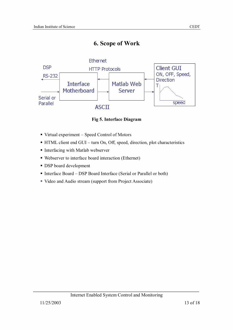
6. Scope of Work
Fig 5. Interface Diagram Virtual experiment – Speed Control of Motors
HTML client end GUI – turn On, Off, speed, direction, plot characteristics Interfacing with Matlab webserver
Webserver to interface board interaction (Ethernet) DSP board development
Interface Board – DSP Board Interface (Serial or Parallel or both) Video and Audio stream (support from Project Associate)
Indian Institute of Science CEDT
Internet Enabled System Control and Monitoring
11/25/2003 14 of 18
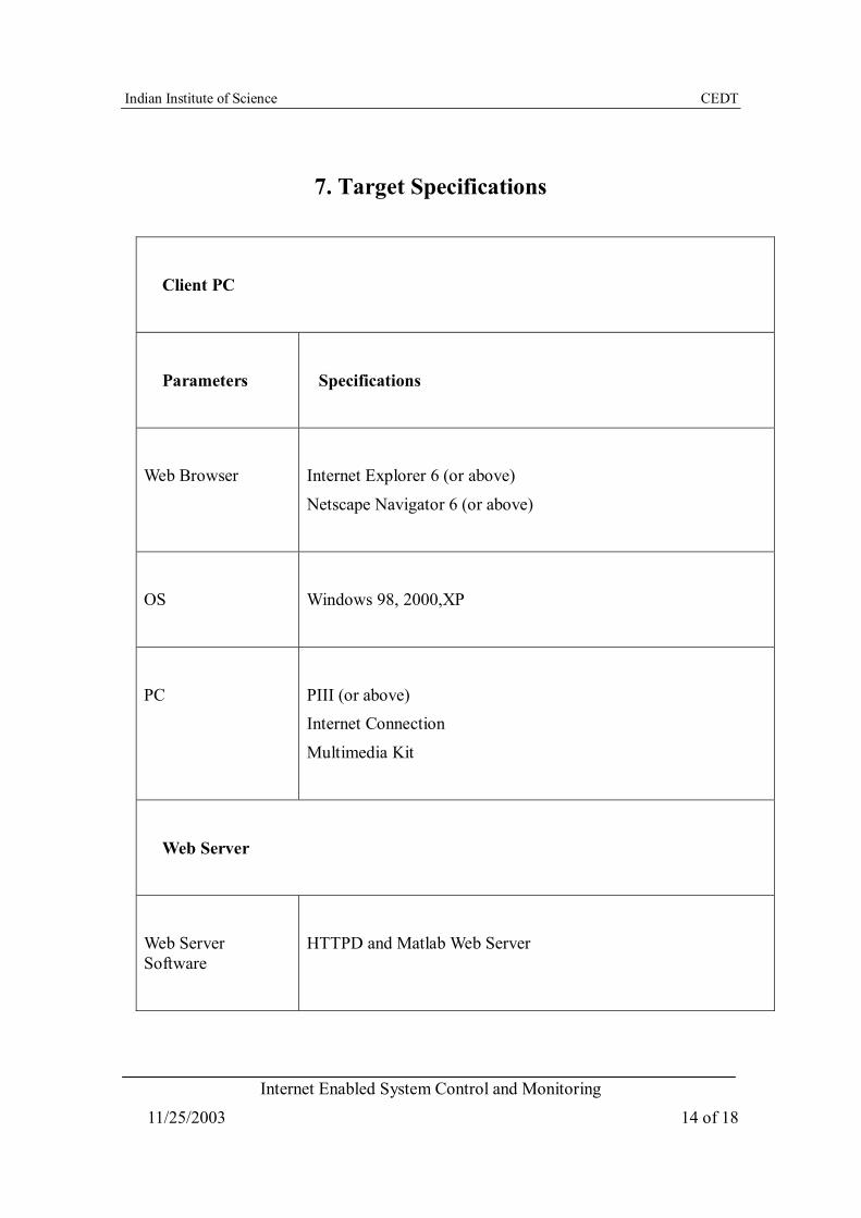
7. Target Specifications
Client PC
Parameters
Specifications
Web Browser
Internet Explorer 6 (or above)
Netscape Navigator 6 (or above)
OS
Windows 98, 2000,XP
PC
PIII (or above) Internet Connection
Multimedia Kit
Web Server
Web Server Software
HTTPD and Matlab Web Server
Indian Institute of Science CEDT
Internet Enabled System Control and Monitoring
11/25/2003 15 of 18
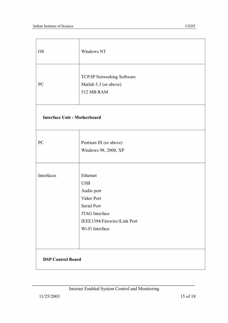
OS
Windows NT
PC
TCP/IP Networking Software Matlab 5.3 (or above)
512 MB RAM
Interface Unit - Motherboard
PC
Pentium III (or above)
Windows 98, 2000, XP
Interfaces
Ethernet
USB Audio port
Video Port
Serial Port
JTAG Interface IEEE1394/Firewire/iLink Port
Wi-Fi Interface
DSP Control Board
Indian Institute of Science CEDT
Internet Enabled System Control and Monitoring
11/25/2003 16 of 18
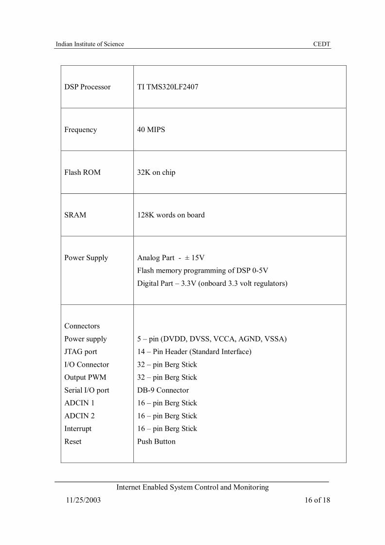
DSP Processor
TI TMS320LF2407
Frequency
40 MIPS
Flash ROM
32K on chip
SRAM
128K words on board
Power Supply
Analog Part - ± 15V Flash memory programming of DSP 0-5V
Digital Part – 3.3V (onboard 3.3 volt regulators)
Connectors
Power supply JTAG port
I/O Connector Output PWM
Serial I/O port ADCIN 1
ADCIN 2
Interrupt
Reset
5 – pin (DVDD, DVSS, VCCA, AGND, VSSA) 14 – Pin Header (Standard Interface)
32 – pin Berg Stick 32 – pin Berg Stick
DB-9 Connector
16 – pin Berg Stick
16 – pin Berg Stick 16 – pin Berg Stick
Push Button
Indian Institute of Science CEDT
Internet Enabled System Control and Monitoring
11/25/2003 17 of 18
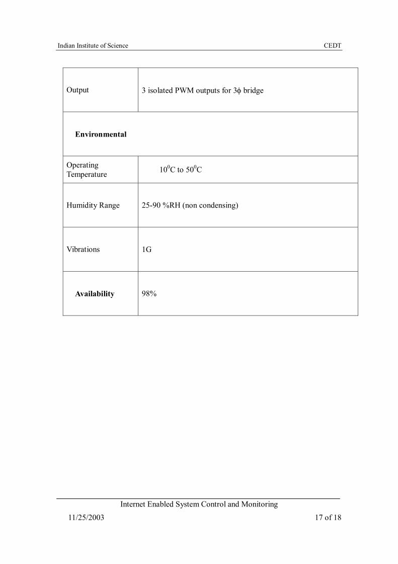
Output
3 isolated PWM outputs for 3φ bridge
Environmental
Operating Temperature 100C to 500C
Humidity Range
25-90 %RH (non condensing)
Vibrations
1G
Availability
98%
Indian Institute of Science CEDT
Internet Enabled System Control and Monitoring
11/25/2003 18 of 18
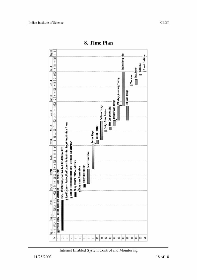
8. Time Plan