internet enabled multi zone thermostat - circuit...
TRANSCRIPT
Internet Enabled Multi‐zone Thermostat Page | 1
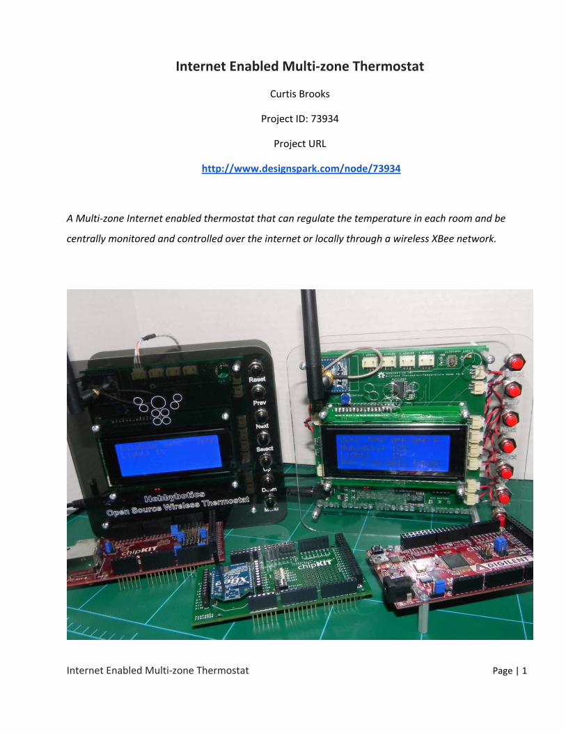
Internet Enabled Multi‐zone Thermostat
Curtis Brooks
Project ID: 73934
Project URL
http://www.designspark.com/node/73934
A Multi‐zone Internet enabled thermostat that can regulate the temperature in each room and be
centrally monitored and controlled over the internet or locally through a wireless XBee network.
Internet Enabled Multi‐zone Thermostat Page | 2
1. Abstract
Heating, ventilation and cooling (HVAC) is the largest source of residential energy consumption.
It takes a lot of energy to heat rooms in the summer and cool them in the winter. Energy Star
estimates that 43% of the energy used in the average home is for heating and cooling rooms
and that the annual energy bill for a typical single family home is approximately $2200 [1]. Most
residential environments have a HVAC system that regulates the temperature based on a
preset condition. The basic scheme is to apply heat when it is too cold, apply cool air when it is
too hot and turn off the system when the temperature is just right. This basic HVAC system is
highly inefficient and thus, we have programmable HVAC systems. A programmable HVAC
system allows one to set parameters for what temperature to maintain and what time to
change that set‐point. This capability comes in handy for when you are away from home and
do not need the entire house maintained at 69 degrees (F), for example. Inherent roadblocks
too many programmable HVAC systems is the initial cost of ownership, annual cost savings
(return for investment) and proper use. The aim of this project is to demonstrate how to use
the chipKIT Max32 along with some cost effective "Do It Yourself (DIY) sensor technology to
address the mentioned roadblocks to programmable HVAC systems. The overall goal is to
demonstrate how a DIY Internet connected wireless thermostat system can be cost effectively
developed in order to decrease the overall residential energy consumption for the United
States and abroad.
2. Introduction
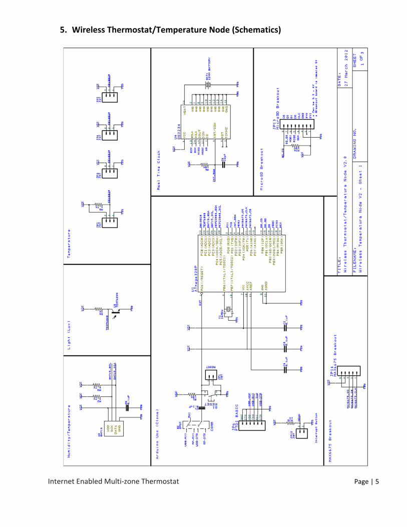
This project is broken out into three different designs with the first being a XBee shield for the
chipKIT Max32, the second a wireless temperature board that contains a SHT15 Humidity
Sensor, a TEMT6000 Light Sensor, a DS3234 Real Time Clock (RTC), two MCP23008 I2C
Input/Output expanders, and connectors for a Secure Digital and MAX6675 Thermocouple
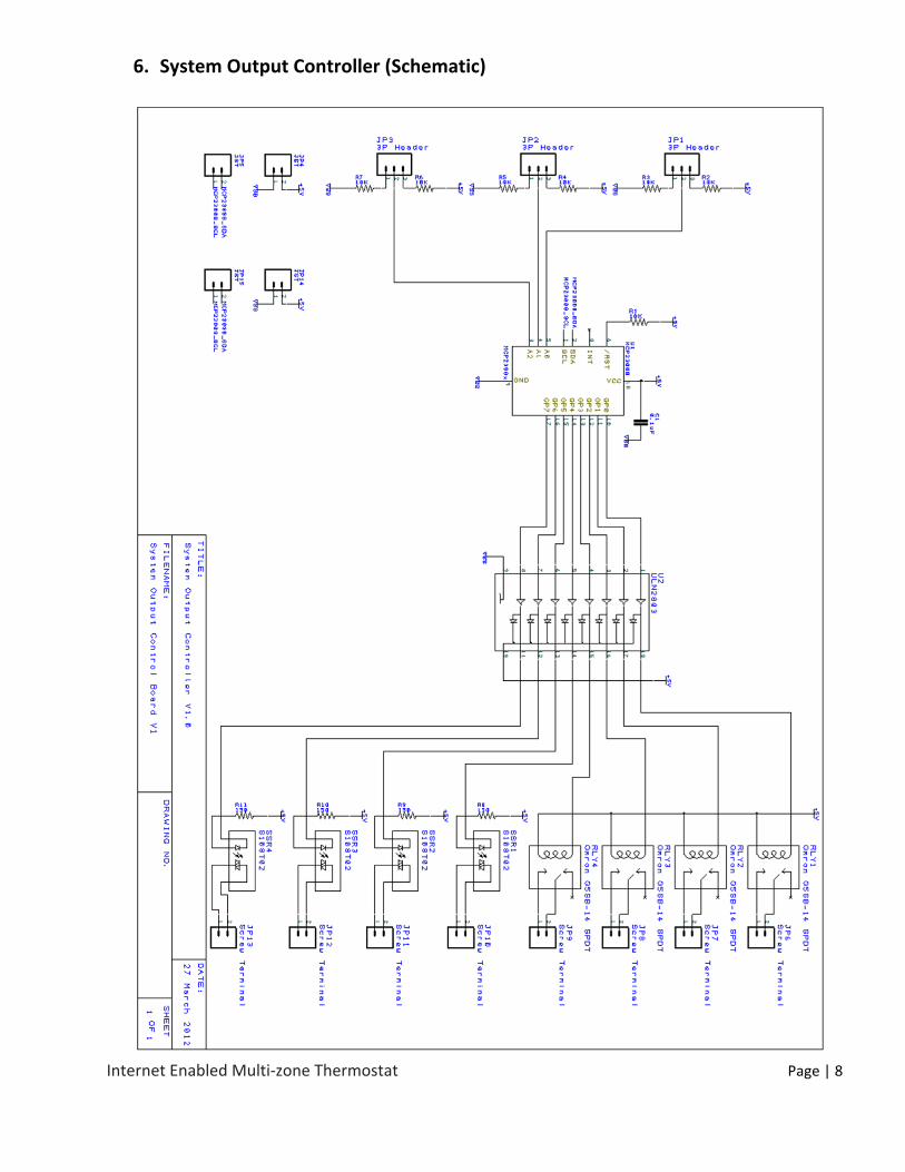
breakout boards. The third design is an I2C controlled output board that has connections for
four Solid State Relays (SSR) and four 5V @5A mechanical relays. Two wireless temperature
control boards and two I2C output boards will be used for this project.
Internet Enabled Multi‐zone Thermostat Page | 3
3. Communications
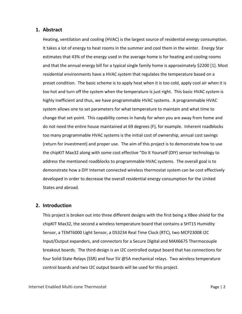
Here is a diagram the show a basic communication scheme for the wireless thermostat
network.
At the head of the setup is a router that provides internet access for the system. The first node
is comprised of a chipKIT Max32, Max32 Ethernet Shield and XBee Shield (developed PCB). The
second node is the Wireless Thermostat that is responsible for controlling the HVAC system and
receiving data from the room nodes. The room nodes, with an output control board attached,
can control a motorized damper to regulate the temperature in each room.
Internet Enabled Multi‐zone Thermostat Page | 4
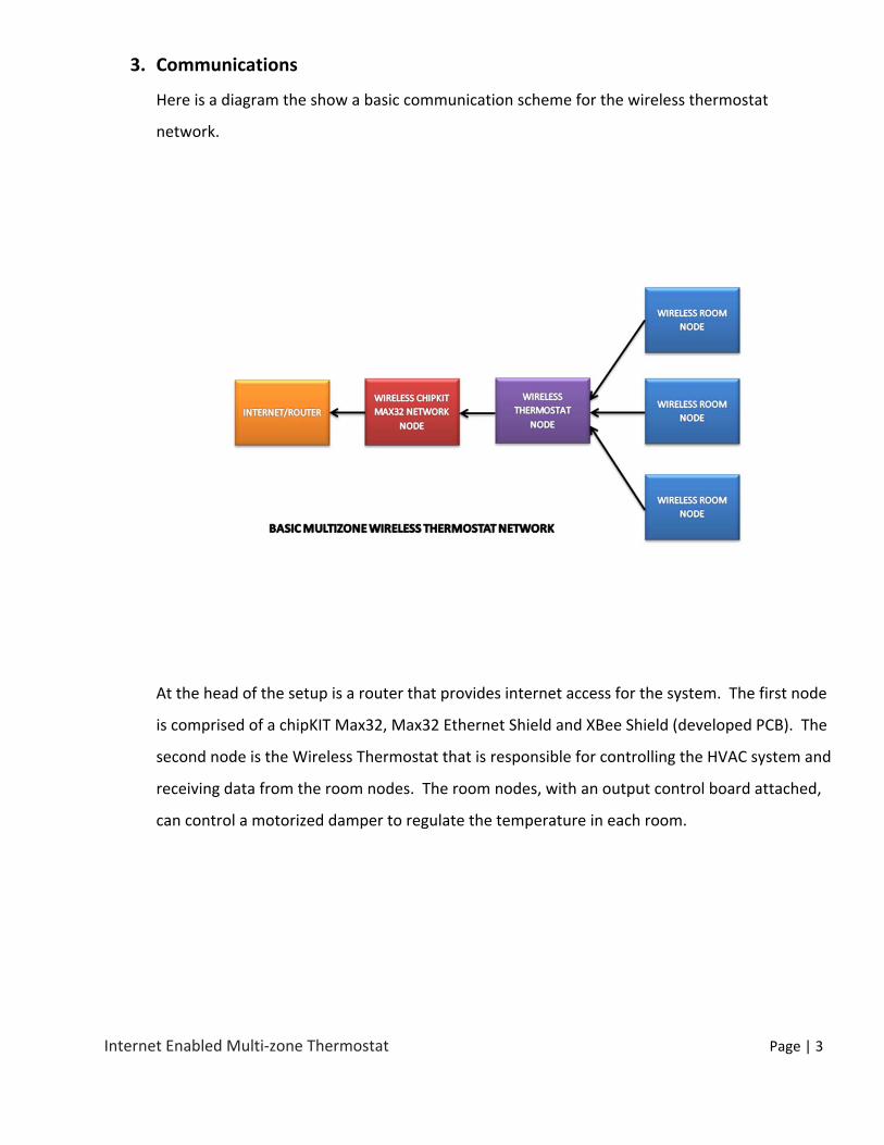
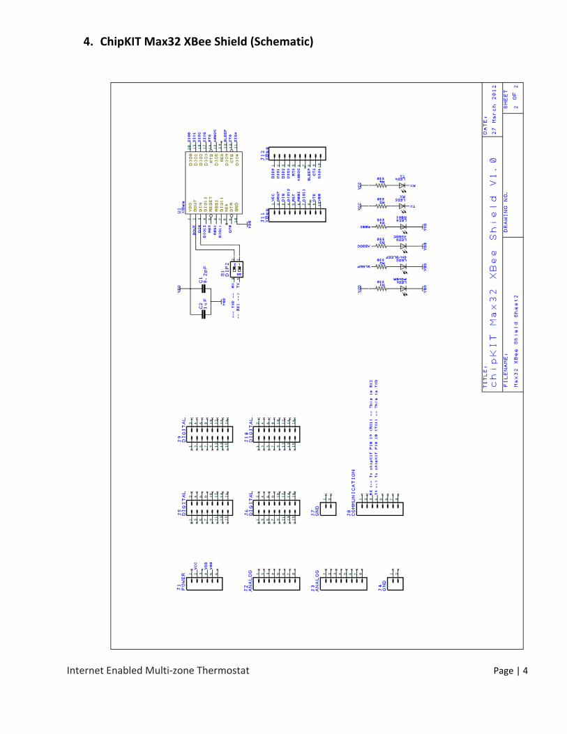
4. ChipKIT Max32 XBee Shield (Schematic)
Internet Enabled Multi‐zone Thermostat Page | 5
5. Wireless Thermostat/Temperature Node (Schematics)
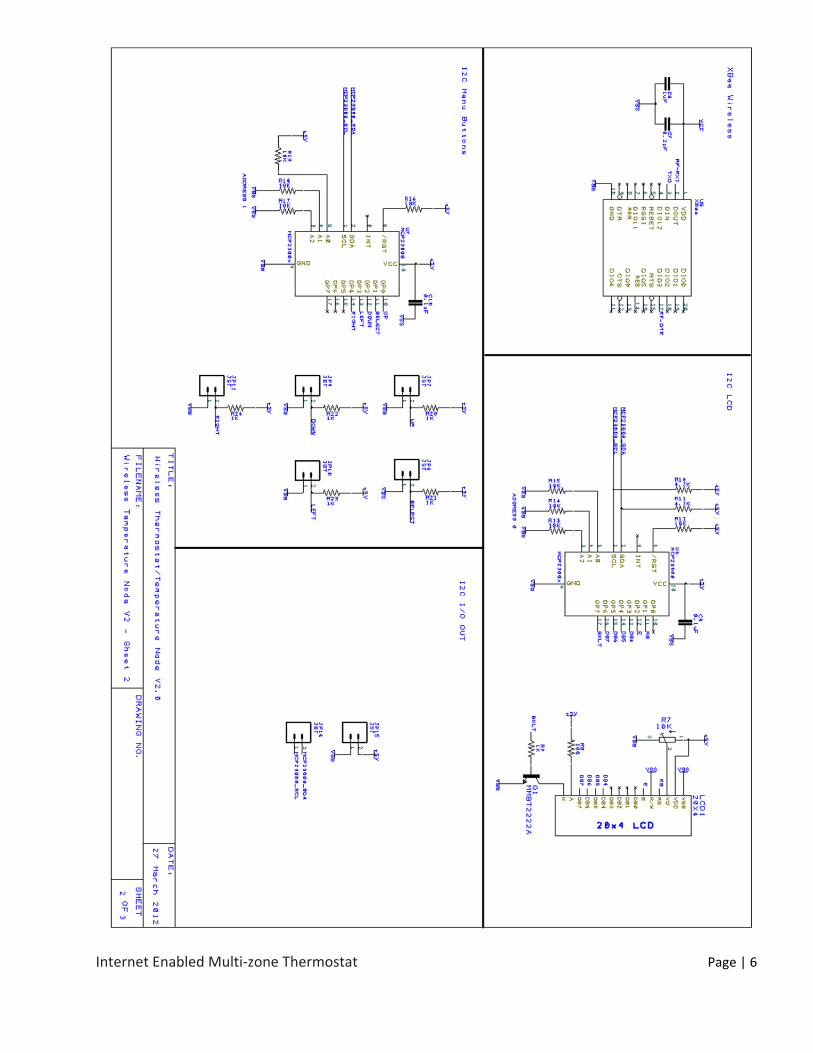
Internet Enabled Multi‐zone Thermostat Page | 6
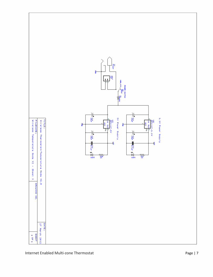
Internet Enabled Multi‐zone Thermostat Page | 7
Internet Enabled Multi‐zone Thermostat Page | 8
6. System Output Controller (Schematic)
Internet Enabled Multi‐zone Thermostat Page | 9
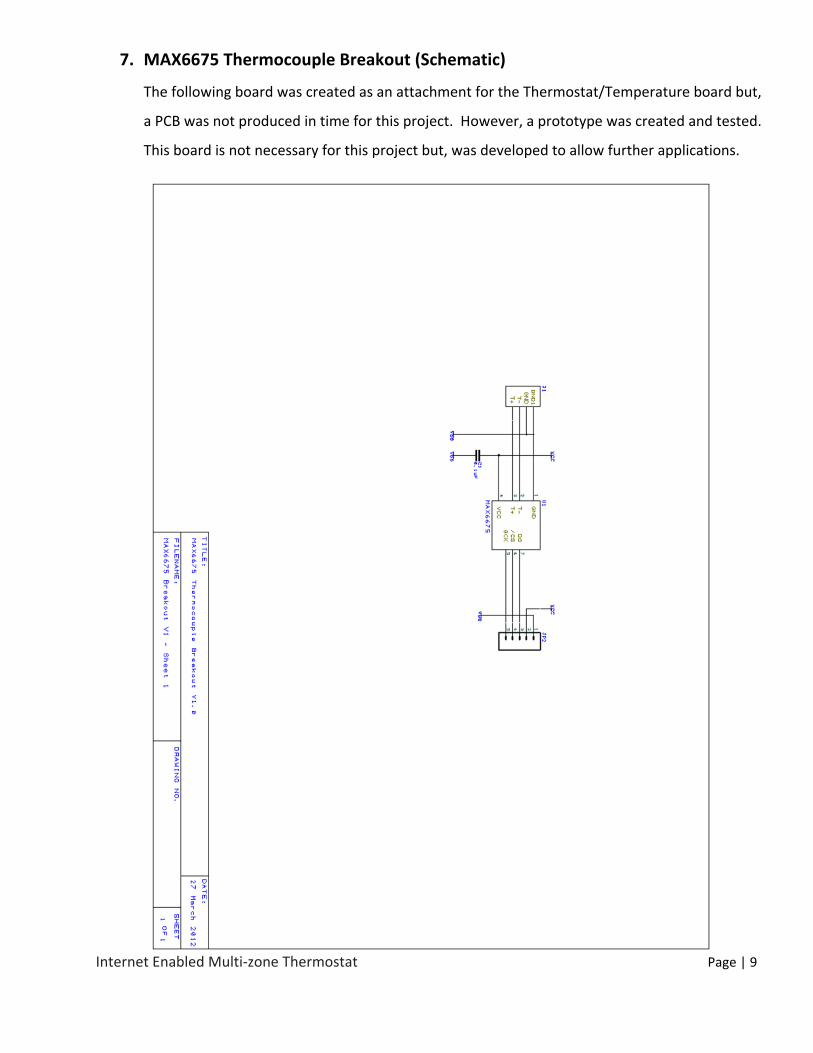
7. MAX6675 Thermocouple Breakout (Schematic)
The following board was created as an attachment for the Thermostat/Temperature board but,
a PCB was not produced in time for this project. However, a prototype was created and tested.
This board is not necessary for this project but, was developed to allow further applications.
Internet Enabled Multi‐zone Thermostat Page | 10
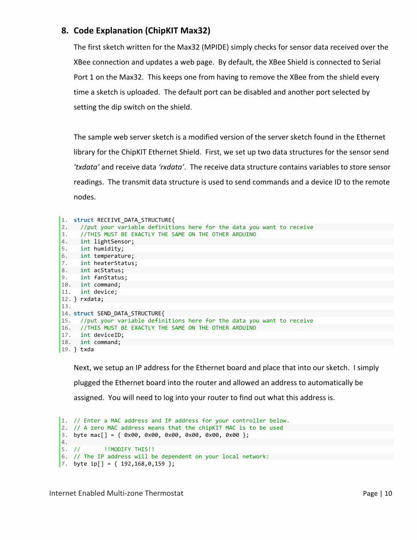
8. Code Explanation (ChipKIT Max32)
The first sketch written for the Max32 (MPIDE) simply checks for sensor data received over the
XBee connection and updates a web page. By default, the XBee Shield is connected to Serial
Port 1 on the Max32. This keeps one from having to remove the XBee from the shield every
time a sketch is uploaded. The default port can be disabled and another port selected by
setting the dip switch on the shield.
The sample web server sketch is a modified version of the server sketch found in the Ethernet
library for the ChipKIT Ethernet Shield. First, we set up two data structures for the sensor send
‘txdata’ and receive data ‘rxdata’. The receive data structure contains variables to store sensor
readings. The transmit data structure is used to send commands and a device ID to the remote
nodes.
1. struct RECEIVE_DATA_STRUCTURE{ 2. //put your variable definitions here for the data you want to receive 3. //THIS MUST BE EXACTLY THE SAME ON THE OTHER ARDUINO 4. int lightSensor; 5. int humidity; 6. int temperature; 7. int heaterStatus; 8. int acStatus; 9. int fanStatus; 10. int command; 11. int device; 12. } rxdata; 13. 14. struct SEND_DATA_STRUCTURE{ 15. //put your variable definitions here for the data you want to receive 16. //THIS MUST BE EXACTLY THE SAME ON THE OTHER ARDUINO 17. int deviceID; 18. int command; 19. } txda
Next, we setup an IP address for the Ethernet board and place that into our sketch. I simply
plugged the Ethernet board into the router and allowed an address to automatically be
assigned. You will need to log into your router to find out what this address is.
1. // Enter a MAC address and IP address for your controller below. 2. // A zero MAC address means that the chipKIT MAC is to be used 3. byte mac[] = { 0x00, 0x00, 0x00, 0x00, 0x00, 0x00 }; 4. 5. // !!MODIFY THIS!! 6. // The IP address will be dependent on your local network: 7. byte ip[] = { 192,168,0,159 };

Internet Enabled Multi‐zone Thermostat Page | 11
Finally, we set up the serial ports, start the Ethernet client, and check for sensor data. This data
will be posted to the serial port and web page.
1. // Initialize the Ethernet server library 2. // with the IP address and port you want to use 3. // (port 80 is default for HTTP): 4. Server server(80); 5. 6. void setup() 7. { 8. // start the Ethernet connection and the server: 9. Ethernet.begin(mac, ip); 10. 11. //Ethernet.begin(); // this will use DHCP 12. server.begin(); 13. 14. // initialize serial 15. Serial.begin(57600); 16. Serial1.begin(57600); 17. }
1. void setup() 2. { 3. // start the Ethernet connection and the server: 4. Ethernet.begin(mac, ip); 5. 6. //Ethernet.begin(); // this will use DHCP 7. server.begin(); 8. 9. // initialize serial 10. Serial.begin(57600); 11. Serial1.begin(57600); 12. } 13. 14. void loop() 15. { 16. // Check for data on the XBee connected to serial port 1 17. if (Serial1.available() >= 7) 18. { 19. // Check for the correct device ID 20. rxdata.device = Serial1.read(); 21. 22. // Get sensor data from port if correct 23. if (rxdata.device == 1) 24. { 25. rxdata.lightSensor = Serial1.read(); 26. rxdata.humidity = Serial1.read(); 27. rxdata.temperature = Serial1.read(); 28. rxdata.heaterStatus = Serial1.read(); 29. rxdata.acStatus = Serial1.read(); 30. rxdata.fanStatus = Serial1.read(); 31. } 32. } 33. 34. delay(1000); 35. 36. // Send it to the default serial port also 37. Serial.print(rxdata.lightSensor);
Internet Enabled Multi‐zone Thermostat Page | 12
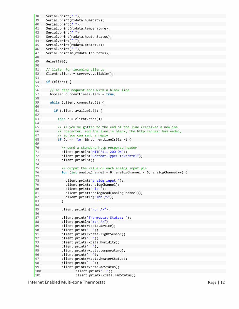
38. Serial.print(" "); 39. Serial.print(rxdata.humidity); 40. Serial.print(" "); 41. Serial.print(rxdata.temperature); 42. Serial.print(" "); 43. Serial.print(rxdata.heaterStatus); 44. Serial.print(" "); 45. Serial.print(rxdata.acStatus); 46. Serial.print(" "); 47. Serial.println(rxdata.fanStatus); 48. 49. delay(100); 50. 51. // listen for incoming clients 52. Client client = server.available(); 53. 54. if (client) { 55. 56. // an http request ends with a blank line 57. boolean currentLineIsBlank = true; 58. 59. while (client.connected()) { 60. 61. if (client.available()) { 62. 63. char c = client.read(); 64. 65. // if you've gotten to the end of the line (received a newline 66. // character) and the line is blank, the http request has ended, 67. // so you can send a reply 68. if (c == '\n' && currentLineIsBlank) { 69. 70. // send a standard http response header 71. client.println("HTTP/1.1 200 OK"); 72. client.println("Content‐Type: text/html"); 73. client.println(); 74. 75. // output the value of each analog input pin 76. for (int analogChannel = 0; analogChannel < 6; analogChannel++) { 77. 78. client.print("analog input "); 79. client.print(analogChannel); 80. client.print(" is "); 81. client.print(analogRead(analogChannel)); 82. client.println("<br />"); 83. } 84. 85. client.println("<br />"); 86. 87. client.print("Thermostat Status: "); 88. client.println("<br />"); 89. client.print(rxdata.device); 90. client.print(" "); 91. client.print(rxdata.lightSensor); 92. client.print(" "); 93. client.print(rxdata.humidity); 94. client.print(" "); 95. client.print(rxdata.temperature); 96. client.print(" "); 97. client.print(rxdata.heaterStatus); 98. client.print(" "); 99. client.print(rxdata.acStatus); 100. client.print(" "); 101. client.print(rxdata.fanStatus);
Internet Enabled Multi‐zone Thermostat Page | 13
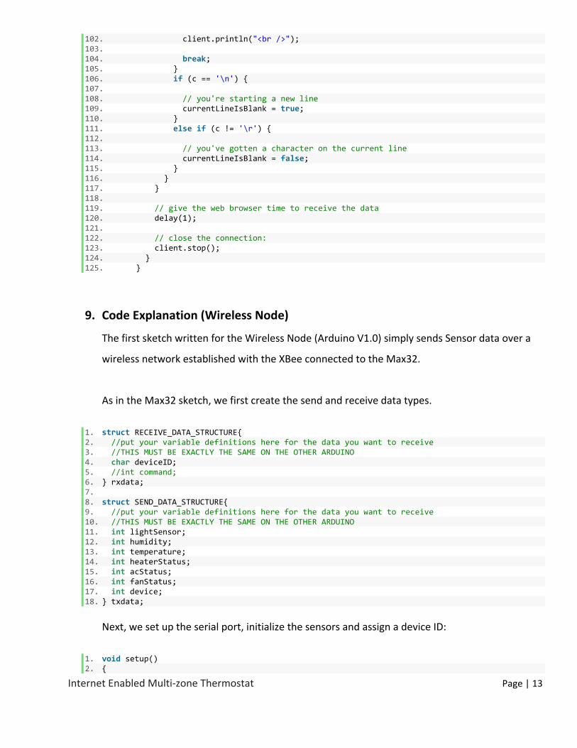
102. client.println("<br />"); 103. 104. break; 105. } 106. if (c == '\n') { 107. 108. // you're starting a new line 109. currentLineIsBlank = true; 110. } 111. else if (c != '\r') { 112. 113. // you've gotten a character on the current line 114. currentLineIsBlank = false; 115. } 116. } 117. } 118. 119. // give the web browser time to receive the data 120. delay(1); 121. 122. // close the connection: 123. client.stop(); 124. } 125. }
9. Code Explanation (Wireless Node)
The first sketch written for the Wireless Node (Arduino V1.0) simply sends Sensor data over a
wireless network established with the XBee connected to the Max32.
As in the Max32 sketch, we first create the send and receive data types.
1. struct RECEIVE_DATA_STRUCTURE{ 2. //put your variable definitions here for the data you want to receive 3. //THIS MUST BE EXACTLY THE SAME ON THE OTHER ARDUINO 4. char deviceID; 5. //int command; 6. } rxdata; 7. 8. struct SEND_DATA_STRUCTURE{ 9. //put your variable definitions here for the data you want to receive 10. //THIS MUST BE EXACTLY THE SAME ON THE OTHER ARDUINO 11. int lightSensor; 12. int humidity; 13. int temperature; 14. int heaterStatus; 15. int acStatus; 16. int fanStatus; 17. int device; 18. } txdata;
Next, we set up the serial port, initialize the sensors and assign a device ID:
1. void setup() 2. {
Internet Enabled Multi‐zone Thermostat Page | 14
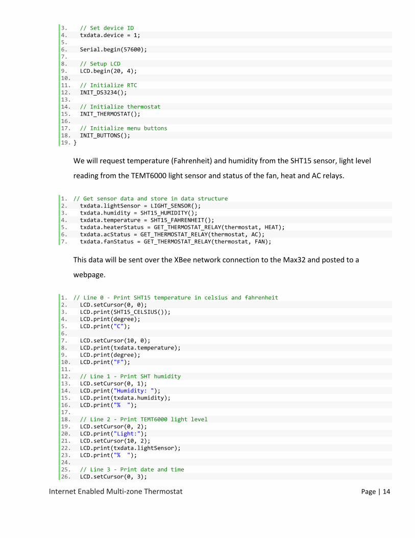
3. // Set device ID 4. txdata.device = 1; 5. 6. Serial.begin(57600); 7. 8. // Setup LCD 9. LCD.begin(20, 4); 10. 11. // Initialize RTC 12. INIT_DS3234(); 13. 14. // Initialize thermostat 15. INIT_THERMOSTAT(); 16. 17. // Initialize menu buttons 18. INIT_BUTTONS(); 19. }
We will request temperature (Fahrenheit) and humidity from the SHT15 sensor, light level
reading from the TEMT6000 light sensor and status of the fan, heat and AC relays.
1. // Get sensor data and store in data structure 2. txdata.lightSensor = LIGHT_SENSOR(); 3. txdata.humidity = SHT15_HUMIDITY(); 4. txdata.temperature = SHT15_FAHRENHEIT(); 5. txdata.heaterStatus = GET_THERMOSTAT_RELAY(thermostat, HEAT); 6. txdata.acStatus = GET_THERMOSTAT_RELAY(thermostat, AC); 7. txdata.fanStatus = GET_THERMOSTAT_RELAY(thermostat, FAN);
This data will be sent over the XBee network connection to the Max32 and posted to a
webpage.
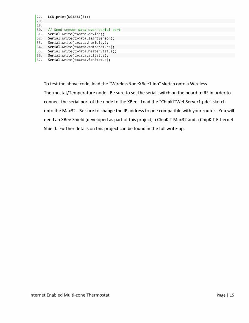
1. // Line 0 ‐ Print SHT15 temperature in celsius and fahrenheit 2. LCD.setCursor(0, 0); 3. LCD.print(SHT15_CELSIUS()); 4. LCD.print(degree); 5. LCD.print("C"); 6. 7. LCD.setCursor(10, 0); 8. LCD.print(txdata.temperature); 9. LCD.print(degree); 10. LCD.print("F"); 11. 12. // Line 1 ‐ Print SHT humidity 13. LCD.setCursor(0, 1); 14. LCD.print("Humidity: "); 15. LCD.print(txdata.humidity); 16. LCD.print("% "); 17. 18. // Line 2 ‐ Print TEMT6000 light level 19. LCD.setCursor(0, 2); 20. LCD.print("Light:"); 21. LCD.setCursor(10, 2); 22. LCD.print(txdata.lightSensor); 23. LCD.print("% "); 24. 25. // Line 3 ‐ Print date and time 26. LCD.setCursor(0, 3);
Internet Enabled Multi‐zone Thermostat Page | 15
27. LCD.print(DS3234(3)); 28. 29. 30. // Send sensor data over serial port 31. Serial.write(txdata.device); 32. Serial.write(txdata.lightSensor); 33. Serial.write(txdata.humidity); 34. Serial.write(txdata.temperature); 35. Serial.write(txdata.heaterStatus); 36. Serial.write(txdata.acStatus); 37. Serial.write(txdata.fanStatus);
To test the above code, load the “WirelessNodeXBee1.ino” sketch onto a Wireless
Thermostat/Temperature node. Be sure to set the serial switch on the board to RF in order to
connect the serial port of the node to the XBee. Load the “ChipKITWebServer1.pde” sketch
onto the Max32. Be sure to change the IP address to one compatible with your router. You will
need an XBee Shield (developed as part of this project, a ChipKIT Max32 and a ChipKIT Ethernet
Shield. Further details on this project can be found in the full write‐up.