international union of operating engineers national hazmat
TRANSCRIPT

International Union of Operating Engineers National Hazmat Program
International Environmental Technology & Training Center
HUMAN FACTORS ASSESSMENT REPORT
June 2001
Lift-Liner™ Systems
Soft-Sided Waste Containers

Research supported by the U.S. Department of Energy’s
National Energy Technology Laboratory under cooperative agreement DE-FC21-95MC32260 with the
Operating Engineers National Hazmat Program, 1293 Airport Road, Beaver, WV 25813,
Phone: 304-253-8674 , Fax (304) 253-7758. Email: [email protected]
This report was prepared with the support of the U.S. Department of Energy. However, any opinions, findings, conclusions, or recommendations expressed herein are those of the author(s) and do not necessarily reflect the views of the DOE.
Frank Hanley, General President

i
Lift-Liner™ Systems Soft-Sided Waste Containers
TABLE OF CONTENTS
1.0 EXECUTIVE SUMMARY ..............................................................1 2.0 INTRODUCTION ..........................................................................1 2.1 Technology Description and Operation...................................................1 2.2 Physical Description and Performance Characteristics ..........................2 2.3 OENHP Safety and Health Assessment ................................................ 4 3.0 METHODOLODY.......................................................................... 4 4.0 RESULTS ..................................................................................... 4 4.1 Hoisting and Rigging...............................................................................4 4.2 Moving Vehicles......................................................................................5 4.3 Tag Lines................................................................................................5 5.0 CONCLUSIONS ........................................................................... 5 5.1 Safety Issues ..........................................................................................5 5.2 Baseline Comparison..............................................................................6 6.0 RECOMMENDATIONS ................................................................ 7 7.0 APPENDIX ................................................................................... 8 7.1 Job Hazard Analysis ..............................................................................8 7.2 Failure Mode Effects Analysis/What if Analysis ...................................12 7.3 Technology Safety Data Sheet ............................................................13 7.4 Acronyms.............................................................................................22

1
Figure 1. Lift-Liner being inserted into the loading frame.
1.0 EXECUTIVE SUMMARY The Lift-Liner™ System provides a cost effective method of transporting and storing low-level hazardous waste. The Lift-Liner™ System is important because it provides an alternative to the costly and awkward metal boxes traditionally used for all hazardous waste. The Transport Plastics Inc. Lift-Liner™ soft-sided waste packaging system includes a 25-mil woven outer polypropylene fabric shell with a 2-mil water resistant coating and a 45-mil double layer polypropylene inner liner. The outer shell is equipped with 18 lifting straps made of 2-inch polyester seat belt webbing material. The system also includes a loading frame used to support the shell and inner liner during loading and a lifting frame. The lifting frame attaches to the lifting straps for hoisting the container from the loading frame onto a transport vehicle. A small forklift can move the empty loading and lifting frames. The empty containers are light and compact enough to move by hand. Each container is 7 X 8 X 5 ft., has a capacity of 260 ft³, and holds up to 24,000 lbs.
The baseline the Lift Liner™ System replaces is 4 X 3 X 8 ft. metal boxes. The obvious advantage of the Lift Liner™ System over the metal boxes is cost. With regard to safety and health, the two each have advantages and disadvantages.
The human factors assessment focused on safety issues and found the following:
• Redesigning the release mechanism of the loading frame is necessary. • Crane operators and engineers, when calculating lifts, do not consider friction
created between the full liner and the loading frame. • Small bar around the base of the loading frame should be redesigned or
removed. • Only qualified operators should operate equipment around or being used with Lift
Liner™ System. • Manufacturer’s recommendations for loading and storage should always be
followed.
2.0 INTRODUCTION 2.1 Technology Description and
Operation The Lift-Liner™ System provides a cost effective method of transporting and storing low-level hazardous waste. The Lift-Liner™ System is important because it provides an alternative to the costly and awkward metal boxes traditionally used for all hazardous waste. The Transport Plastics Inc. Lift-Liner™ soft-sided waste packaging system includes a 25-mil woven outer polypropylene fabric shell

2
with a 2-mil water resistant coating and a 45-mil double layer polypropylene inner liner. The outer shell is equipped with 18 lifting straps made of 2-inch polyester seat belt webbing material. (Figure 1.) The containers meet the U.S. Department of Transportation (DOT) requirements for transport of low specific activity and surface contaminated objects (strong tight rule), subject to the requirements of 49 CFR §173.427, §173.410, and §173.24. The “strong tight rule” is a general DOT requirement for packages of low level waste to be “strong, tight packages” that were “designed and constructed, with their contents so limited, that under conditions normally incident to transportation:
• There will be no significant release of the hazardous materials to the environment; • The effectiveness of the package will not be substantially reduced; and • There will be no mixture of gases or vapors in the package which could, through
any credible spontaneous increase of heat or pressure, or through an explosion, significantly reduce the effectiveness of the packaging.
The system also includes a loading frame used to support the shell and inner liner during loading. A lifting frame attaches to the lifting straps for hoisting the container from the loading frame onto a transport vehicle. A small forklift can move the empty loading frame and lifting frame. The empty containers are light and compact enough to move by hand. Each container is 7 X 8 X 5 ft., has a capacity of 260 ft³, and holds up to 24,000 lbs. 2.2 Physical Description and Performance Characteristics Outer Liner Specifications
• Overall Size 96” x 88” x 60” (Nominal) +/- 1” all dimensions • Loadable Size 96” x 86” x 54” (Nominal) +/- 1” all dimensions • Volume Capacity 258 cu. ft. (Nominal) • Weight Empty 42 lbs. • Weight Capacity 24,000 lbs. • Lift Capacity 24,000 lbs. @ 125% certified
Lift Liner™ Construction (Figure 2.)
• Fabric Woven and coated polypropylene • Lift Straps 18 each @ 6,000 lb. Tensile test each woven
polyester fabric

3
Figure 2. Lift-Liner unfolded by user.
• Closure Top Flaps 4 each; 2 full overlapping, 2 centering • Securing Straps 20 each 1” ply webbing with corresponding
receiver loops Inner Liner Specifications
• Overall Size 96” x 85” x 72” (Nominal) +/- 1” all dimensions • Volume Capacity 258 cu. ft. • Weight Empty 38 lbs.
Inner Liner Construction
• Fabric Double layers of woven and coated polypropylene fabric
• Closure Top Flaps 4 each; 2 overlapping, 2 centering Lifting Frame Specifications/ Dimensions
• Overall Size 92” x 82” x 24” (Nominal) +/- 1” all dimensions • Empty Weight 1,240 lbs. • Lifting Weight Capacity 24,000 lbs. @ 125% certified (per DOE-STD-
1090 Hoisting and Rigging Devices) • Design Capacity 40,000 lbs. • Means to Lift Crane of Forklift
Lifting Frame Construction
• Frame All steel per ASTM A-500 (USA / CAN) • Hooks 3 ton carbon steel (USA)

4
Loading Frame Specifications/ Dimensions
• Overall Size 92” x 82” x 60” ID (Nominal) +/- 1” per wall • Weight Capacity 960 lbs.
Loading Frame Construction
• Frame 1 ½” square tube steel • Walls 10 gauge galvanized steel sheet • Floor 1 ½” square tube steel grid and 10 gauge steel
sheet 2.3 OPERATING ENGINEERS NATIONAL HAZMAT PROGRAM
SAFETY AND HEALTH ASSESSMENT The 88” Lift Liner™ system including lifting frame, loading frame, and liner were used for the assessment. A Caterpillar 416C was used to load the Lift Liner™. A Grove 750 50-ton Rough Terrain Crane was used to pick the full liner from the loading frame. The assessment was conducted at the International Environmental Technology and Training Center located at 1293 Airport Road, Beaver WV 25813. Loose soil was used during the testing demonstration. 3.0 METHODOLOGY Operating Engineers and safety professionals completed a Job Hazard Analysis (JHA), Failure Mode and Effect Analysis (FMEA), and Technology Safety Data Sheet (TSDS) during the demonstration. The Lift Liner™ system was assessed using the unique method of employing thirty-two (32) Operating Engineers under the guidance of five Operating Engineers who are veterans of human factors assessments, and two Safety and Health professionals. The thirty-two Operating Engineers were divided into three groups; each group was responsible for completing either a JHA, FMEA, or TSDS. After the demonstration the groups discussed each point and arrived at a consensus for each point before recording it electronically. The developer provided additional input.
4.0 RESULTS 4.1 Hoisting and Rigging Although the technology components are the liner, loading frame, and lifting frame, hoisting and rigging are an integral part of the process. Crane operators and users should only use the proper straps, shackles, hooks, etc. and perform inspections and

5
Figure 3. Lift-Liner System is filled using a caterpillar 416C.
Figure 4. Full Lift-Liner is picked out of the loading frame.
maintenance when required on these items. Proper procedures when performing lifts should also be followed at all times, including use of outriggers, tag lines, and calculating safe lifts. OSHA stipulates these requirements in 29 CFR §1926.550, Cranes and derricks.
4.2 Moving Vehicles
As with hoisting and rigging, moving vehicles are part of the process and not the technology. The Lift Liner™ System depends on a fork truck to position the loading frame, a loader to load the liner, and a crane to lift the full liner. (Figure 3.) When using the Lift Liner™ System, operators and workers should be trained on the proper use of moving vehicles. The appropriate OSHA reference is 29 CFR §1926.602, Material Handling Equipment.
4.3 Tag Lines Tag lines may be defined as a line attached to a load in order to control the load being lifted preventing it from striking individuals or objects on the ground. When employees are moving or placing the lifting frame, a tag line should be used to ensure the lifting frame does not strike individuals. Tag lines should be attached to the liner when the full liner is being removed. The only exception is if the tag line will create a hazard. OSHA requirements can be found in 29 CFR § 1926.550(g)(6)(iii). 5.0 CONCLUSIONS 5.1 Safety Issues The Lift Liner™ System is a simple and inherently safe technology. The major safety and health issues associated with its use are those issues traditionally associated with construction activities and are peripheral to the use of the Lift Liner™ System. Adherence to proper procedures when using a crane, material handling equipment, and fork-trucks is just as important as following the manufacturers standard operating procedures when using the Lift Liner™ System. (Figure 4.)

6
The main issue with the Lift Liner™ System occurs when the liner is bulging to the point it cannot be removed from the loading frame without releasing the pins on the sides. This creates several hazards. Workers are forced to remove the pins with a hand tool releasing the sides under pressure onto the safety chains. The sudden release of pressure outward may strike individuals standing in front of the sides or cause the failure of the safety chains freeing the sides to collapse. Bulging liners also affect how safely the crane is being operated. Crane operators evaluate their lift by taking into account variables such as weight of the load, equipment being used, the angle of the boom, wind, and many other variables. After each variable has been considered and evaluated crane operators make a decision on whether the load may be successfully and safely lifted. The bulging liners, even with the sides of the loading frame released, create friction against the loading frame possibly making the lift too heavy and therefore unsafe. The manufacturer recommends workers use a ladder when pushing the edges of the liner into the corners of the loading frame, moving debris inside the liner around manually, or when tying straps. The loading frame has a small bar running around the outside of the frame approximately one foot off the ground. Workers are likely to abuse this using it as a step.
Under the right conditions, ambient temperature, storage methods, and waste material, the liners may ignite and burn. Users of the Lift Liner™ System should always follow the manufacturer’s recommendations for storing the liners out of direct sunlight if possible and being conscious of the material being loaded and transported. 5.2 Baseline Comparison The baseline the Lift Liner™ System replaces is the 4 X 3 X 8 ft. metal boxes. The obvious advantage of the Lift Liner™ System over the metal boxes is cost. With regard to safety and health, the two each have advantages and disadvantages.
• The empty liners can be transported and stored in great quantities while the empty boxes must be stacked safely.
• Loads must be packed evenly in the metal boxes to prevent the load from shifting; the full liners will find their own shape depending on the material being loaded.
• Metal boxes can only be filled as high as the top of the box; anything sticking up farther will prevent the box from closing and require individuals to position the load manually. The flaps on the liners can be placed over any load sticking up and tightened using the straps.
• Manufacturer recommendations for loading the liners are to place sharp jagged objects such as re-bar in only after the bottom of the liner has been lined with soil or something similar. In the event these instructions are not followed or there is only sharp, jagged material to be loaded the liner may be breached exposing workers to contaminants.

7
6.0 RECOMMENDATIONS Redesigning the loading frame to mechanically release the pressure of a bulging liner rather than manually releasing the pins will effectively engineer out the hazards associated with being struck by the sides of the loading frame or the sides collapsing. The manufacturer has stated that this is a top priority and will be accomplished by using a double throw lever. Further consideration may be given to using a hydraulic system to allow the loading frame to be opened and closed automatically. When the liner is bulging with loose debris it is difficult for the liner to be removed from the loading frame. Releasing the four sides alleviates the pressure but friction between the liner and loading frame does exist. Crane operators and engineers do not take this into consideration when calculating their lifts and therefore may be making unsafe picks. Until the loading frame is redesigned in such a way that it totally releases the bulging liner crane operators and engineers should be given technology specific training with emphasis on calculating lifts. Redesigning or removing the bar that runs around the loading frame approximately one foot off the ground will reduce the risk of hazards associated with slips, trips, or falls. If the manufacturer intends for this to be used as a step a flat, non-slip, surface should replace the bar. If the manufacturer’s recommendations are for workers to only use a ladder when pushing the corners of the liner down or adjusting debris inside the liner then the bar should be removed. At the very least the bar should be labeled with a No Step label. While the use of material handling equipment, cranes, and fork trucks are only part of the process, the safety of the Lift Liner™ System depends in part on how safely each of these are operated. Only qualified and certified operators who practice safe and OSHA-approved work practices should be allowed to operate equipment when using the Lift Liner™ System. The operators should receive technology specific training with emphasis on the manufacturer’s recommendations on loading the liner properly.

8
7.0 APPENDIX 7.1 Job Hazard Analysis
JOB HAZARD ANALYSIS
SEQUENCE OF JOB STEPS POTENTIAL ACCIDENT
OR HAZARD NEW PROCEDURE OR
PROTECTION
PHASE 1 – UNLOADING EQUIPMENT/SETUP Using incorrect machine. Loading frame designed for use with forklift only.
Use the correct machine.
Loading frame may be too heavy for forklift.
Check capacity of forklift prior to arrival.
Unload loading frame.
Operator not licensed. Check license and training.
Use of improper or damaged rigging.
Inspect rigging before each use.
Rigging the lifting frame.
Using improper shackles and chokers.
Inspect before each use to ensure the correct shackles and chokers are being used.
Un-safe crane. Pre-Ops (check crane capacity).
Workers may get too close to the crane.
Set up barricades.
Setting up the crane.
Crane may be unsteady due to uneven or soft ground.
Cribbing under out-riggers.
Lifting or lowering sides may result in sprains or strains.
Use proper lifting techniques or seek help.
Setting up the loading frame.
Pinch points from removing or installing pins and closing the sides together.
Use the proper hand protection. Be conscious of the hazards.
Move the loading frame to the loading area.
A moving vehicle or the loading frame may strike users.
Only forklift certified operators using forklifts. Workers on the ground should be informed of the planned move.

9
JOB HAZARD ANALYSIS
SEQUENCE OF JOB STEPS POTENTIAL ACCIDENT
OR HAZARD NEW PROCEDURE OR
PROTECTION
PHASE 1 – UNLOADING EQUIPMENT/SETUP CONTINUED Carry or drag the liner to the loading frame.
Strains or sprains. Use proper lifting techniques or seek assistance from others.
Place empty or partially unfolded liner into frame.
Strains or sprains may result from overhead lift.
Use proper lifting techniques or seek assistance from others.
Unfold and pull outer liner over sides of the loading frame using straps.
Sprains or strains pulling and tugging flaps over sides of loading frame.
Do not jerk on the liner and seek assistance.
Strains and sprains from extending over the side of the frame pushing with the pole.
Use the proper tool provided by the manufacturer.
Straighten out liner by pushing down corners of liner into corners of loading frame using a pole. Slips, trips or falls from the
side of the loading frame or from a ladder.
Do not climb the side of loading frame and only use appropriate and approved ladder by OSHA.
Climbing in and out of loading frame to push the corners of the liner into the corners of the loading frame.
Slips, trips or falls while climbing in and out of the loading frame.
The loading frame is not designed to climb in and out. Corners should be straightened only using a ladder and not by climbing in and out of loading frame.
PHASE 2 – OPERATION Load container. Workers around loading
frame may be struck by loader, by or caught between loader and frame.
Control area around loading frame. Operators should be aware of workers on the ground at all times.
Fold flaps of inner and outer liner and tie straps holding flaps of liner in place.
Crawling on or up loading frame may result in slips or fall.
Only use OSHA approved ladders. Discourage climbing on loading frame.

10
JOB HAZARD ANALYSIS
SEQUENCE OF JOB STEPS POTENTIAL ACCIDENT
OR HAZARD NEW PROCEDURE OR
PROTECTION
PHASE 2 – OPERATION CONTINUED Pinch points under straps. Workers must be aware of
hazards associated with tying the straps.
Fold flaps of inner and outer liner and tie straps holding flaps of liner in place. (continued from previous page) Wrong straps may be
fastened across the liner. Color-code the straps.
Workers may be struck by swinging lifting frame.
Use a tag line.
Lifting straps may be on the wrong side of the rail.
Double check straps prior to pick.
Lifting straps may be twisted. Double check straps prior to pick.
Connect the lifting frame to the full liner.
Use of faulty or improper hooks. Or hooks not rated for a sufficient load.
Inspect rigging prior to use to make sure hooks are approved type and load and make sure safety clasps are functioning properly.
Boom and swing not centered over the lift.
Check boom and swing before lift.
Lifting frame tilts to one side. Unequal load prevents liner from being removed from loading frame.
Replace lifting frame and evenly distribute material.
Load will not come out of loading frame easily.
Release side door latches by removing pins.
Side door latches catch hands when removing pins.
Use proper equipment to release pins on latch. Stand to one side of frame when pins are removed.
Lift the full liner out of the loading frame.
Safety chains may break when pins are removed to release latch.
Stand to one side during release.

11
JOB HAZARD ANALYSIS
SEQUENCE OF JOB STEPS POTENTIAL ACCIDENT
OR HAZARD NEW PROCEDURE OR
PROTECTION
PHASE 3 – MAINTENANCE Pinch points removing pins and laying sides down.
Use the proper PPE and workers informed and trained on possible hazards.
Maintenance of loading frame may require all four sides to be opened.
Ergonomic hazards associated with lifting and bending of the sides.
Use proper lifting techniques and seek assistance.
PHASE 4 – DECONTAMINATION Decontamination of loading frame and lifting frame.
Workers may be exposed to contaminants.
Use the proper PPE and awareness when working on, around, or with contaminated equipment.
PHASE 5 – LOADING/DISMANTLEMENT Remove or replace pins on each side holding latches in place.
Pinch points from removing and replacing pins and from sides opening and closing.
Use proper PPE and workers should be trained on hazards and practice good awareness at all times.
Lift or lower the sides the loading frame.
Ergonomic hazards, back strains or sprains.
Practice proper lifting techniques and seek assistance when possible.
Using crane or fork truck, load both the loading frame and lifting frame onto transport.
Struck by or caught between moving vehicles.
Use only certified operators to run motor vehicles. Each employee should be informed of all planned lifts.

12
7.2 Failure Mode and Effects Analysis
FAILURE MODE AND EFFECTS ANALYSIS
FAILURE MODE EFFECT
Failure of straps or rigging due to faulty equipment or improper use.
Struck by and falling object hazards created.
Failure of pins on the sides of the loading frame holding the four sides together.
Sudden release of pressure inside frame. Frame will travel approximately six inches until safety chains catch. The sides may strike individuals during the release of pressure.
Failure of chains when side pins are released. Failure of chains will result in sudden release of energy inside the loading frame pushing the sides of the loading frame outward. The sides of the loading frame are capable of laying flat on the ground. The sides of the loading frame may strike individuals near the sides during a sudden release of energy.
Failure of liner due to improper loading. Failure of the liner will result in the loss and/or exposure to contaminants inside.
Failure of liner’s fire resistance. Combustion of liner resulting in fire and release of hazardous waste.

13
7.3 Technology Safety Data Sheet
Lift Liner™ Systems Soft Sided Waste Containers
TECHNOLOGY SAFETY DATA SHEET
SECTION 1: TECHNOLOGY IDENTITY Manufacturer’s Name and Address: Emergency Contact: Transport Plastics, Inc. 190 Transport Dr PO Box 12 Sweetwater, TN 37874
Ken Grumski 1-800-603-8277 (7:30 – 4:30 EST Mon – Sat) 1-724-452-9300
Other Names: Information Contact: Ken Grumski 1-800-603-8277 1-724-452-9300
Lift Liner MHF Logistics 129 McCarrell Ln Zelienople, PA 16063 Date Prepared: Tech ID: 2240 8-22-01
Prepared by: Operating Engineers National Hazmat Program

14
SECTION 2: PROCESS DESCRIPTION The Transport Plastics Inc. Lift-Liner™ soft-sided waste packaging system includes a 25-mil woven outer polypropylene fabric shell with a 2-mil water resistant coating and a 45-mil double layer polypropylene inner liner. The outer shell is equipped with 18 lifting straps made of 2-inch polyester seat belt webbing material. The containers meet the U.S. Department of Transportation requirements for transport of low specific activity and surface contaminated objects (strong tight rule), subject to the requirements of 49 CFR §173.427, §173.410, and §173.24. The system also includes a loading frame used to support the shell and inner liner during loading and a lifting frame. The lifting frame attaches to the lifting straps for hoisting the container from the loading frame onto a transport vehicle. A small forklift can move the empty loading frame and lifting frame. The empty containers are light and compact enough to move by hand. Each container is 7 X 8 X 5 ft., has a capacity of 260 ft³, and holds up to 24,000 lbs.
15
SECTION 3: TECHNOLOGY DIAGRAMS OR PICTURES
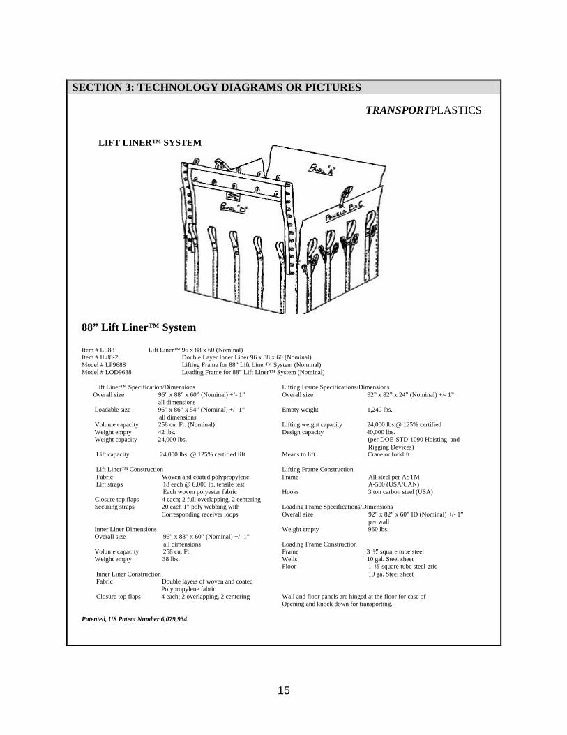
88” Lift Liner™ System Item # LL88 Lift Liner™ 96 x 88 x 60 (Nominal) Item # IL88-2 Double Layer Inner Liner 96 x 88 x 60 (Nominal) Model # LP9688 Lifting Frame for 88” Lift Liner™ System (Nominal) Model # LOD9688 Loading Frame for 88” Lift Liner™ System (Nominal) Lift Liner™ Specification/Dimensions Lifting Frame Specifications/Dimensions Overall size 96” x 88” x 60” (Nominal) +/- 1” Overall size 92” x 82” x 24” (Nominal) +/- 1” all dimensions Loadable size 96” x 86” x 54” (Nominal) +/- 1” Empty weight 1,240 lbs. all dimensions Volume capacity 258 cu. Ft. (Nominal) Lifting weight capacity 24,000 lbs @ 125% certified Weight empty 42 lbs. Design capacity 40,000 lbs. Weight capacity 24,000 lbs. (per DOE-STD-1090 Hoisting and Rigging Devices) Lift capacity 24,000 lbs. @ 125% certified lift Means to lift Crane or forklift Lift Liner™ Construction Lifting Frame Construction Fabric Woven and coated polypropylene Frame All steel per ASTM Lift straps 18 each @ 6,000 lb. tensile test A-500 (USA/CAN) Each woven polyester fabric Hooks 3 ton carbon steel (USA) Closure top flaps 4 each; 2 full overlapping, 2 centering Securing straps 20 each 1” poly webbing with Loading Frame Specifications/Dimensions Corresponding receiver loops Overall size 92” x 82” x 60” ID (Nominal) +/- 1” per wall Inner Liner Dimensions Weight empty 960 lbs. Overall size 96” x 88” x 60” (Nominal) +/- 1” all dimensions Loading Frame Construction Volume capacity 258 cu. Ft. Frame 3 ½” square tube steel Weight empty 38 lbs. Wells 10 gal. Steel sheet Floor 1 ½” square tube steel grid Inner Liner Construction 10 ga. Steel sheet Fabric Double layers of woven and coated Polypropylene fabric Closure top flaps 4 each; 2 overlapping, 2 centering Wall and floor panels are hinged at the floor for case of Opening and knock down for transporting. Patented, US Patent Number 6,079,934
TRANSPORTPLASTICS
LIFT LINER™ SYSTEM
16
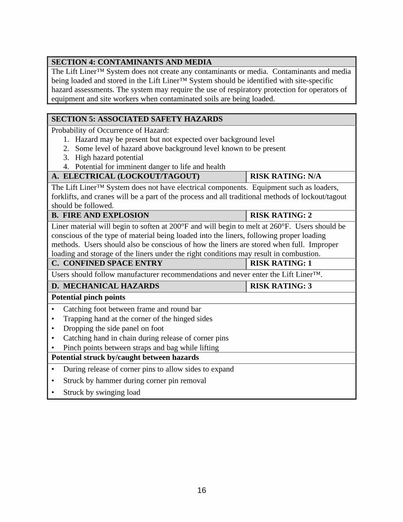
SECTION 4: CONTAMINANTS AND MEDIA The Lift Liner™ System does not create any contaminants or media. Contaminants and media being loaded and stored in the Lift Liner™ System should be identified with site-specific hazard assessments. The system may require the use of respiratory protection for operators of equipment and site workers when contaminated soils are being loaded.
SECTION 5: ASSOCIATED SAFETY HAZARDS Probability of Occurrence of Hazard:
1. Hazard may be present but not expected over background level 2. Some level of hazard above background level known to be present 3. High hazard potential 4. Potential for imminent danger to life and health
A. ELECTRICAL (LOCKOUT/TAGOUT) RISK RATING: N/A The Lift Liner™ System does not have electrical components. Equipment such as loaders, forklifts, and cranes will be a part of the process and all traditional methods of lockout/tagout should be followed. B. FIRE AND EXPLOSION RISK RATING: 2 Liner material will begin to soften at 200°F and will begin to melt at 260°F. Users should be conscious of the type of material being loaded into the liners, following proper loading methods. Users should also be conscious of how the liners are stored when full. Improper loading and storage of the liners under the right conditions may result in combustion. C. CONFINED SPACE ENTRY RISK RATING: 1 Users should follow manufacturer recommendations and never enter the Lift Liner™.
D. MECHANICAL HAZARDS RISK RATING: 3 Potential pinch points
• Catching foot between frame and round bar • Trapping hand at the corner of the hinged sides • Dropping the side panel on foot • Catching hand in chain during release of corner pins • Pinch points between straps and bag while lifting Potential struck by/caught between hazards
• During release of corner pins to allow sides to expand
• Struck by hammer during corner pin removal
• Struck by swinging load

17
SECTION 5: ASSOCIATED SAFETY HAZARDS CONTINUED Probability of Occurrence of Hazard:
1 Hazard may be present but not expected over background level 2 Some level of hazard above background level known to be present 3 High hazard potential
4 Potential for imminent danger to life and health
E. PRESSURE HAZARDS RISK RATING: 3 Load exerts outward pressure on liners and frame. Any release of this pressure carries some degree of hazard. The frame is capable of releasing pressure two different ways and therefore capable of failing two ways, the first through the pins holding the sides together, and the second being the safety chains holding the sides together when the pins have been removed. Additionally, the liners may fail if they are loaded incorrectly and have been breached. F. TRIPPING AND FALLING RISK RATING: 3
• Unfolding and placing bag in frame presents multiple tripping hazards due to numerous straps.
• If frame has a side down for loading, the open side presents a potential for slippery walking surface and the gap between the sheet metal and the tube steel that make up the wall frame presents a tripping hazard.
• Fall hazards are numerous while loading the liner into the frame. There are no measures in place to ensure safe climbing/stepping surfaces.
• After securing the liner, the strap tails present a tripping hazard.
• Falling off the frame while arranging the liner bottom in the loading frame.
G. LADDERS AND PLATFORMS RISK RATING: 1 Ladders are the recommended means of accessing/observing inside the frame. The proper use of ladders will alleviate the hazards associated with climbing on the loading frame. H. MOVING VEHICLES RISK RATING: 3 The Lift Liner™ System does not have any moving vehicles but does depend on them. Without moving vehicles to move the loading frame and lift the full liner out of the loading frame the technology does not work. The Lift Liner™ System does not create any new hazards associated with moving vehicles but users should be conscious of the high level of hazard traditionally associated with moving vehicles, especially cranes. I. BURIED UTILITIES, DRUMS, AND TANKS RISK RATING: N/A J. PROTRUDING OBJECTS RISK RATING: 1 Corner pins used to hold the sides protrude approximately 2 inches. K. GAS CYLINDERS RISK RATING: N/A L. TRENCHING AND EXCAVATIONS RISK RATING: N/A

18
SECTION 5: ASSOCIATED SAFETY HAZARDS CONTINUED Probability of Occurrence of Hazard:
1 Hazard may be present but not expected over background level 2 Some level of hazard above background level known to be present 3 High hazard potential
4 Potential for imminent danger to life and health
M. OVERHEAD LIFTS RISK RATING: 2 Tag lines should be attached to the lifting frame to prevent the load from shifting/spinning. The lifting straps and liner are collectively rated at 24,000 lbs. Breaking strength collectively for all 18 straps is 108,000 lbs. N. OVERHEAD HAZARDS RISK RATING: 2 The Lift Liner™ System does not create any new hazards associated with overhead hazards. Users should be conscious of hazards traditionally associated with lifting heavy objects overhead using a crane.
SECTION 6: ASSOCIATED HEALTH HAZARDS Probability of Occurrence of Hazard:
1 Hazard may be present but not expected over background level 2 Some level of hazard above background level known to be present 3 High hazard potential
4 Potential for imminent danger to life and health
A. INHALATION HAZARD RISK RATING: N/A The system will be used with contaminated soils that could release dusts. Consequently, the hazards should be evaluated each time the system is used. B. SKIN ABSORPTION RISK RATING: N/A C. HEAT STRESS RISK RATING: N/A The Lift Liner™ System does not create additional risk for heat stress, only the ambient temperature needs to be considered and the level of PPE being used.
D. NOISE RISK RATING: N/A The Lift Liner™ System does not create noise. Users should take into consideration machinery being used with or around the Lift Liner™ System such as the loader and crane. E. NON-IONIZING RADIATION RISK RATING: N/A F. IONIZING RADIATION RISK RATING: N/A G. COLD STRESS RISK RATING: N/A The Lift Liner™ System does not create additional risk for cold stress, only the ambient temperature needs to be considered and the level of PPE being used.

19
SECTION 6: ASSOCIATED HEALTH HAZARDS CONTINUED Probability of Occurrence of Hazard:
1 Hazard may be present but not expected over background level 2 Some level of hazard above background level known to be present 3 High hazard potential
4 Potential for imminent danger to life and health
H. ERGONOMIC HAZARDS RISK RATING: 2
• Pulling, grabbing, tugging, and tying straps and/or bags • Most work performed was at shoulder-height or above • Weight of the liner (40 lbs) being lifted to shoulder height and over the top rail I. OTHER RISK RATING: 2 Following the manufacturer’s recommended procedures for loading are paramount. Failure to do so may result in a breach of the liner, overloading, or even combustion.
SECTION 7: PHASE ANALYSIS A. CONSTRUCTION/START-UP
• Moving vehicles (forklift) needed for set-up and positioning of loading frame and lifting frame.
• Ergonomic hazards associated with overhead lift of 40lb folded bag over and into loading frame.
• Slips, trips, or falls from the side of the loading frame or from a ladder when opening the liner inside the loading frame.
• If one or all the fours sides are released and laying down users should be aware of pinch points associated with the pins and closing the four sides together.

20
SECTION 7: PHASE ANALYSIS CONTINUED B. OPERATION
• Proper loading of the liner per manufacturer recommendations must be followed. Only non-flammable material with sharp protruding objects loaded only after the liner is lined with loose debris.
• Operators should also use caution when loading the bag by not striking the liner or loading frame with the equipment.
• Users should use caution and be aware of ergonomic hazards associated with tying the bag. Numerous belts and ropes must be secured on both the inner and outer liner. These should be secured as tight as possible. Users may be exposed to strains or sprains.
• Only proper and inspected rigging should be used when fastening the lifting frame to the crane.
• Hand signals with a tag line should be used during the lift.
• When calculating the load prior to the pick, crane operators should take into consideration the friction of the bag on the sides of the loading frame.
• In the event the liner is bulging to the point it cannot be easily removed from the loading frame and the pins are removed to release the pressure, users should stand clear of sides keeping clear of the sudden release of energy outward.
• Users should also keep in mind that once the pins are removed the safety chains are now the only things holding the four sides together.
C. MAINTENANCE
• Removing pins and/or safety chains to release sides may create pinch points.
• Users should use proper lifting techniques when lowering or raising the sides to avoid sprains or strains.
• If the sides are lowered, users should be aware of slips, trips, and falls moving in and out of the loading frame via the lowered sides.
• Climbing on the sides of the loading frame or using a ladder when performing maintenance with the sides up and fastened may result in slips, trips, or falls.

21
SECTION 7: PHASE ANALYSIS CONTINUED D. DECOMMISSIONING The Lift Liner™ System does not have any mechanical or electrical components. Decontamination of the technology will only involve those hazards addressed in the maintenance section.
• Removing pins and/or safety chains to release sides may create pinch points.
• Users should use proper lifting techniques when lowering or raising the sides to avoid sprains or strains.
• If the sides are lowered, users should be aware of slips, trips, and falls moving in and out of the loading frame via the lowered sides.
• Climbing on the sides of the loading frame or using a ladder when performing maintenance with the sides up and fastened may result in slips, trips, or falls.
SECTION 8: HEALTH AND SAFETY PLAN REQUIRED ELEMENTS A. AIR MONITORING Site-specific requirements will apply B. WORKER TRAINING Hoisting and rigging
Training to manufacturer’s specifications regarding proper use of the product Proper lifting techniques/ergonomics
Training specific for support machinery and associated hazards
OSHA Construction Outreach HAZWOPER
C. EMERGENCY RESPONSE The Lift Liner™ System does not require additional emergency response other than already dictated by OSHA. D. MEDICAL SURVEILLANCE The Lift Liner™ System does not create a need for medical surveillance. Only medical surveillance as a result of site-specific hazards should be implemented. E. INFORMATIONAL PROGRAM Standard operating procedures with manufacturer recommendations should be provided to all users. The Lift Liner™ System does not require additional informational programs other than those that should already be in place, namely an effective HAZCOM program addressing the contaminants being loaded into the liners. SECTION 9: COMMENTS AND SPECIAL CONSIDERATIONS Proper/selective loading, tying, and handling techniques are crucial to ensuring the safety and health of the workforce involved in this technology.

22
7.4 Acronyms ASTM American Society for Testing and Materials CAN Canada CFR Code of Federal Regulations DOT Department of Transportation FMEA Failure Modes and Effects Analysis JHA Job Hazard Analysis OSHA Occupational Safety and Health Administration STD Standard TSDS Technology Safety Data Sheet USA United States of America